

Page 1

ZyXEL G-1000 v2
Wireless-11g Access Point
User’s Guide
Version 3.60
Edition 1
3/2006
Page 2

Page 3

ZyXEL G-1000 v2 User’s Guide
Copyright
Copyright © 2006 by ZyXEL Communications Corporation.
The contents of this publication may not be reproduced in any part or as a whole, transcribed,
stored in a retrieval system, translated into any language, or transmitted in any form or by any
means, electronic, mechanical, magnetic, optical, chemical, photocopying, manual, or
otherwise, without the prior written permission of ZyXEL Communications Corporation.
Published by ZyXEL Communications Corporation. All rights reserved.
Disclaimer
ZyXEL does not assume any liability arising out of the application or use of any products, or
software described herein. Neither does it convey any license under its patent rights nor the
patent rights of others. ZyXEL further reserves the right to make changes in any products
described herein without notice. This publication is subject to change without notice.
Trademarks
ZyNOS (ZyXEL Network Operating System) is a registered trademark of ZyXEL
Communications, Inc. Other trademarks mentioned in this publication are used for
identification purposes only and may be properties of their respective owners.
Copyright 3
Page 4

ZyXEL G-1000 v2 User’s Guide
Interference Statements and
Federal Communications Commission (FCC) Interference Statement
This device complies with Part 15 of FCC rules. Operation is subject to the following two
conditions:
• This device may not cause harmful interference.
• This device must accept any interference received, including interference that may cause
undesired operations.
This equipment has been tested and found to comply with the limits for a Class B digital
device pursuant to Part 15 of the FCC Rules. These limits are designed to provide reasonable
protection against harmful interference in a residential installation. This equipment generates,
uses, and can radiate radio frequency energy, and if not installed and used in accordance with
the instructions, may cause harmful interference to radio communications. However, there is
no guarantee that interference will not occur in a particular installation
Certifications
If this equipment does cause harmful interference to radio/television reception, which can be
determined by turning the equipment off and on, the user is encouraged to try to correct the
interference by one or more of the following measures:
• Reorient or relocate the receiving antenna.
• Increase the separation between the equipment and the receiver.
• Connect the equipment into an outlet on a circuit different from that to which the receiver
is connected.
• Consult the dealer or an experienced radio/TV technician for help.
This Class B digital apparatus complies with Canadian ICES-003.
Cet appareil numérique de la classe B est conforme à la norme NMB-003 du Canada.
FCC Caution
Any changes or modifications not expressly approved by the party responsible for compliance
could void the user's authority to operate this equipment.
IMPORTANT NOTE: FCC Radiation Exposure Statement
This equipment complies with FCC radiation exposure limits set forth for an uncontrolled
environment. This equipment should be installed and operated with minimum distance 20cm
between the radiator & your body.
4 Interference Statements and Certifications
Page 5

ZyXEL G-1000 v2 User’s Guide
This transmitter must not be co-located or operating in conjunction with any other antenna or
transmitter.
ZyXEL Communications Corporation declared that G-1000 v2 is limited in CH1~11 from
2400 to 2483.5 MHz by specified firmware controlled in USA.
注意 !
依據 低功率電波輻射性電機管理辦法
第十二條 經型式認證合格之低功率射頻電機,非經許可,公司、商號或使用
者均不得擅自變更頻率、加大功率或變更原設計之特性及功能。
第十四條 低功率射頻電機之使用不得影響飛航安全及干擾合法通信;經發現
有干擾現象時,應立即停用,並改善至無干擾時方得繼續使用。
前項合法通信,指依電信規定作業之無線電信。低功率射頻電機須忍
受合法通信或工業、科學及醫療用電波輻射性電機設備之干擾。
Certifications
1 Go to www.zyxel.com
2 Select your product from the drop-down list box on the ZyXEL home
page to go to that product's page.
3 Select the certification you wish to view from this page.
Interference Statements and Certifications 5
Page 6

ZyXEL G-1000 v2 User’s Guide
For your safety, be sure to read and follow all warning notices and instructions.
• To reduce the risk of fire, use only No. 26 AWG (American Wire Gauge) or larger
telecommunication line cord.
• Do NOT open the device or unit. Opening or removing covers can expose you to
dangerous high voltage points or other risks. ONLY qualified service personnel can
service the device. Please contact your vendor for further information.
• Use ONLY the dedicated power supply for your device. Connect the power cord or
power adaptor to the right supply voltage (110V AC in North America or 230V AC in
Europe).
• Do NOT use the device if the power supply is damaged as it might cause electrocution.
• If the power supply is damaged, remove it from the power outlet.
• Do NOT attempt to repair the power supply. Contact your local vendor to order a new
power supply.
• Place connecting cables carefully so that no one will step on them or stumble over them.
Do NOT allow anything to rest on the power cord and do NOT locate the product where
anyone can walk on the power cord.
• If you wall mount your device, make sure that no electrical, gas or water pipes will be
damaged.
• Do NOT install nor use your device during a thunderstorm. There may be a remote risk of
electric shock from lightning.
• Do NOT expose your device to dampness, dust or corrosive liquids.
• Do NOT use this product near water, for example, in a wet basement or near a swimming
pool.
• Make sure to connect the cables to the correct ports.
• Do NOT obstruct the device ventilation slots, as insufficient airflow may harm your
device.
• Do NOT store things on the device.
• Connect ONLY suitable accessories to the device.
Safety Warnings
6 Safety Warnings
Page 7

ZyXEL G-1000 v2 User’s Guide
ZyXEL Limited Warranty
ZyXEL warrants to the original end user (purchaser) that this product is free from any defects
in materials or workmanship for a period of up to two years from the date of purchase. During
the warranty period, and upon proof of purchase, should the product have indications of failure
due to faulty workmanship and/or materials, ZyXEL will, at its discretion, repair or replace the
defective products or components without charge for either parts or labor, and to whatever
extent it shall deem necessary to restore the product or components to proper operating
condition. Any replacement will consist of a new or re-manufactured functionally equivalent
product of equal or higher value, and will be solely at the discretion of ZyXEL. This warranty
shall not apply if the product has been modified, misused, tampered with, damaged by an act
of God, or subjected to abnormal working conditions.
Note
Repair or replacement, as provided under this warranty, is the exclusive remedy of the
purchaser. This warranty is in lieu of all other warranties, express or implied, including any
implied warranty of merchantability or fitness for a particular use or purpose. ZyXEL shall in
no event be held liable for indirect or consequential damages of any kind to the purchaser.
To obtain the services of this warranty, contact ZyXEL's Service Center for your Return
Material Authorization number (RMA). Products must be returned Postage Prepaid. It is
recommended that the unit be insured when shipped. Any returned products without proof of
purchase or those with an out-dated warranty will be repaired or replaced (at the discretion of
ZyXEL) and the customer will be billed for parts and labor. All repaired or replaced products
will be shipped by ZyXEL to the corresponding return address, Postage Paid. This warranty
gives you specific legal rights, and you may also have other rights that vary from country to
country.
ZyXEL Limited Warranty 7
Page 8

ZyXEL G-1000 v2 User’s Guide
Please have the following information ready when you contact customer support.
• Product model and serial number.
• Warranty Information.
• Date that you received your device.
• Brief description of the problem and the steps you took to solve it.
Customer Support
METHOD
LOCATION
CORPORATE
HEADQUARTERS
(WORLDWIDE)
CZECH REPUBLIC
DENMARK
FINLAND
FRANCE
GERMANY
HUNGARY
KAZAKHSTAN
NORTH AMERICA
NORWAY
SUPPORT E-MAIL TELEPHONE
SALES E-MAIL FAX FTP SITE
support@zyxel.com.tw +886-3-578-3942 www.zyxel.com
sales@zyxel.com.tw +886-3-578-2439 ftp.zyxel.com
info@cz.zyxel.com +420-241-091-350 www.zyxel.cz ZyXEL Communications
info@cz.zyxel.com +420-241-091-359
support@zyxel.dk +45-39-55-07-00 www.zyxel.dk ZyXEL Communications A/S
sales@zyxel.dk +45-39-55-07-07
support@zyxel.fi +358-9-4780-8411 www.zyxel.fi ZyXEL Communications Oy
sales@zyxel.fi +358-9-4780 8448
info@zyxel.fr +33-4-72-52-97-97 www.zyxel.fr ZyXEL France
+33-4-72-52-19-20
support@zyxel.de +49-2405-6909-0 www.zyxel.de ZyXEL Deutschland GmbH.
sales@zyxel.de +49-2405-6909-99
support@zyxel.hu +36-1-3361649 www.zyxel.hu ZyXEL Hungary
info@zyxel.hu +36-1-3259100
http://zyxel.kz/support +7-3272-590-698 www.zyxel.kz ZyXEL Kazakhstan
sales@zyxel.kz +7-3272-590-689
support@zyxel.com 1-800-255-4101
+1-714-632-0882
sales@zyxel.com +1-714-632-0858 ftp.us.zyxel.com
support@zyxel.no +47-22-80-61-80 www.zyxel.no ZyXEL Communications A/S
sales@zyxel.no +47-22-80-61-81
1
WEB SITE
www.europe.zyxel.com
ftp.europe.zyxel.com
www.us.zyxel.com ZyXEL Communications Inc.
REGULAR MAIL
ZyXEL Communications Corp.
6 Innovation Road II
Science Park
Hsinchu 300
Ta iw a n
Czech s.r.o.
Modranská 621
143 01 Praha 4 - Modrany
Ceská Republika
Columbusvej
2860 Soeborg
Denmark
Malminkaari 10
00700 Helsinki
Finland
1 rue des Vergers
Bat. 1 / C
69760 Limonest
France
Adenauerstr. 20/A2 D-52146
Wuerselen
Germany
48, Zoldlomb Str.
H-1025, Budapest
Hungary
43, Dostyk ave.,Office 414
Dostyk Business Centre
050010, Almaty
Republic of Kazakhstan
1130 N. Miller St.
Anaheim
CA 92806-2001
U.S.A.
Nils Hansens vei 13
0667 Oslo
Norway
8 Customer Support
Page 9

ZyXEL G-1000 v2 User’s Guide
METHOD
LOCATION
POLAND
RUSSIA
SPAIN
SWEDEN
UKRAINE
UNITED KINGDOM
1. “+” is the (prefix) number you enter to make an international telephone call.
SUPPORT E-MAIL TELEPHONE
SALES E-MAIL FAX FTP SITE
info@pl.zyxel.com +48-22-5286603 www.pl.zyxel.com ZyXEL Communications
+48-22-5206701
http://zyxel.ru/support +7-095-542-89-29 www.zyxel.ru ZyXEL Russia
sales@zyxel.ru +7-095-542-89-25
support@zyxel.es +34-902-195-420 www.zyxel.es ZyXEL Communications
sales@zyxel.es +34-913-005-345
support@zyxel.se +46-31-744-7700 www.zyxel.se ZyXEL Communications A/S
sales@zyxel.se +46-31-744-7701
support@ua.zyxel.com +380-44-247-69-78 www.ua.zyxel.com ZyXEL Ukraine
sales@ua.zyxel.com +380-44-494-49-32
support@zyxel.co.uk +44-1344 303044
08707 555779 (UK only)
sales@zyxel.co.uk +44-1344 303034 ftp.zyxel.co.uk
1
WEB SITE
REGULAR MAIL
ul.Emilli Plater 53
00-113 Warszawa
Poland
Ostrovityanova 37a Str.
Moscow, 117279
Russia
Alejandro Villegas 33
1º, 28043 Madrid
Spain
Sjöporten 4, 41764 Göteborg
Sweden
13, Pimonenko Str.
Kiev, 04050
Ukraine
www.zyxel.co.uk ZyXEL Communications UK
Ltd.,11 The Courtyard,
Eastern Road, Bracknell,
Berkshire, RG12 2XB,
United Kingdom (UK)
Customer Support 9
Page 10

ZyXEL G-1000 v2 User’s Guide
10 Customer Support
Page 11

ZyXEL G-1000 v2 User’s Guide
Table of Contents
Copyright ..................................................................................................................3
Interference Statements and Certifications ........................................................... 4
Safety Warnings ....................................................................................................... 6
ZyXEL Limited Warranty.......................................................................................... 7
Customer Support.................................................................................................... 8
Table of Contents ................................................................................................... 11
List of Figures ........................................................................................................ 17
List of Tables .......................................................................................................... 21
Preface ....................................................................................................................25
Chapter 1
Getting to Know Your Device ................................................................................ 27
1.1 Introducing the ZyXEL G-1000 v2 .....................................................................27
1.2 Features .............................................................................................................27
1.2.1 Physical Features .....................................................................................27
1.2.2 Firmware Features ....................................................................................28
1.3 Applications for the G-1000 v2 ...........................................................................30
1.3.1 Internet Access Application ......................................................................31
1.3.2 Corporation Network Application ..............................................................31
1.4 Front Panel of the G-1000 ..................................................................................31
Chapter 2
Introducing the Web Configurator........................................................................ 33
2.1 Web Configurator Overview ...............................................................................33
2.2 Accessing the G-1000 v2 Web Configurator ......................................................33
2.3 Resetting the G-1000 v2 ....................................................................................34
2.3.1 .Procedure To Use The Reset Button .......................................................34
2.4 Navigating the Web Configurator .......................................................................35
2.4.1 Navigation Panel .......................................................................................35
2.4.3 Status: Packet Statistics ............................................................................38
2.4.4 Status: WLAN Association List .................................................................39
Table of Contents 11
Page 12

ZyXEL G-1000 v2 User’s Guide
Chapter 3
Wizard Setup .......................................................................................................... 41
3.1 Wizard Setup Overview ......................................................................................41
3.2 General Setup ....................................................................................................41
3.3 Wizard Setup Wireless LAN ...............................................................................42
3.3.1 Name (SSID), Channel ID and Security ...................................................42
3.3.2 Configuring WEP or WPA(2) PSK Security ..............................................43
3.3.3 IP Address Assignment ............................................................................46
3.3.4 Apply Settings ...........................................................................................47
Chapter 4
Wireless LAN .......................................................................................................... 49
4.1 Wireless Network Overview ...............................................................................49
4.2 Wireless Security Overview ...............................................................................50
4.2.1 SSID .........................................................................................................50
4.2.2 MAC Address Filter ...................................................................................50
4.2.3 User Authentication ..................................................................................50
4.2.4 Encryption .................................................................................................51
4.3 Additional Wireless Terms ..................................................................................52
4.4.1 No Security ...............................................................................................54
4.4.2 WEP Encryption ........................................................................................55
4.4.3 WEP Encryption Screen ...........................................................................55
4.4.4 WPA(2)-PSK .............................................................................................56
4.4.5 WPA(2) Authentication Screen .................................................................58
Chapter 5
IP and DNS Screens............................................................................................... 63
5.1 Configuring IP ....................................................................................................63
5.2 Configuring DNS ................................................................................................64
Chapter 6
Remote Management Configuration .................................................................... 67
6.1.1 Remote Management Limitations .............................................................67
6.1.2 System Timeout .......................................................................................68
6.3 Telnet ..................................................................................................................69
6.6 SNMP .................................................................................................................71
6.6.1 Supported MIBs ........................................................................................72
6.6.2 SNMP Traps .............................................................................................73
Chapter 7
System .................................................................................................................... 75
7.1 General Setup ....................................................................................................75
7.1.1 General Setup and System Name ............................................................75
12 Table of Contents
Page 13

ZyXEL G-1000 v2 User’s Guide
Chapter 8
Logs ........................................................................................................................ 81
8.1.1 Alerts and Logs .........................................................................................81
8.4 SMTP Error Messages .......................................................................................84
Chapter 9
Tools ........................................................................................................................ 87
9.2.1 Backup Configuration ...............................................................................89
9.2.2 Restore Configuration ...............................................................................89
9.2.3 Back to Factory Defaults ...........................................................................90
Chapter 10
Introducing the SMT ..............................................................................................93
10.1 Connect to your G-1000 v2 Using Telnet .........................................................93
10.2 Changing the System Password ......................................................................93
10.3 G-1000 v2 SMT Menus Overview ...................................................................94
10.4 Navigating the SMT Interface ...........................................................................95
Chapter 11
General Setup......................................................................................................... 97
Chapter 12
LAN Setup............................................................................................................... 99
12.1 LAN Setup ........................................................................................................99
12.2 TCP/IP Ethernet Setup .....................................................................................99
12.3 Wireless LAN Setup .......................................................................................100
12.3.1 Configuring MAC Address Filter ...........................................................102
12.3.2 Configuring Roaming ............................................................................103
Chapter 13
SNMP Configuration ............................................................................................ 105
Chapter 14
System Security ................................................................................................... 107
14.1 System Password ..........................................................................................107
14.2 Configuring External RADIUS Server ............................................................107
14.3 802.1x ............................................................................................................109
Chapter 15
System Information and Diagnosis .................................................................... 113
15.1 System Status ................................................................................................ 113
15.2 System Information ........................................................................................ 115
15.2.1 System Information ...............................................................................115
15.2.2 Console Port Speed ..............................................................................116
Table of Contents 13
Page 14

ZyXEL G-1000 v2 User’s Guide
15.3 Log and Trace ................................................................................................ 116
15.3.1 Syslog Logging ..................................................................................... 117
15.4 Diagnostic ...................................................................................................... 117
Chapter 16
Firmware and Configuration File Maintenance ................................................. 119
16.1 Filename Conventions ...................................................................................119
16.2 Backup Configuration .....................................................................................120
16.2.1 Backup Configuration Using FTP .........................................................120
16.2.2 Using the FTP command from the DOS Prompt ..................................121
16.2.3 Backup Configuration Using TFTP .......................................................122
16.2.4 Example: TFTP Command ...................................................................123
16.2.5 Backup Via Console Port ......................................................................123
Chapter 17
System Maintenance and Information ...............................................................125
17.1 Command Interpreter Mode ...........................................................................125
17.2 Time and Date Setting ....................................................................................126
17.3 Remote Management Setup ..........................................................................127
17.3.1 Telnet ....................................................................................................127
17.3.2 FTP .......................................................................................................127
17.3.3 Web ......................................................................................................127
17.3.4 Remote Management Setup .................................................................128
17.3.5 Remote Management Limitations .........................................................129
17.4 Remote Management and NAT ......................................................................129
17.5 System Timeout .............................................................................................130
Chapter 18
Troubleshooting ................................................................................................... 131
Appendix A
Product Specifications ........................................................................................ 133
Appendix B
Brute-Force Password Guessing Protection..................................................... 135
Appendix C
Setting up Your Computer’s IP Address............................................................ 137
Appendix D
IP Address Assignment Conflicts ......................................................................149
Appendix E
IP Subnetting ........................................................................................................ 153
Appendix F
14 Table of Contents
Page 15

ZyXEL G-1000 v2 User’s Guide
Command Interpreter........................................................................................... 161
Appendix G
Log Descriptions.................................................................................................. 163
Appendix H
Wireless LAN and IEEE 802.11 ...........................................................................167
Appendix I
Wireless LAN Security......................................................................................... 173
Appendix J
Types of EAP Authentication.............................................................................. 185
Appendix K
Antenna Selection and Positioning Recommendation..................................... 187
Table of Contents 15
Page 16

ZyXEL G-1000 v2 User’s Guide
16 Table of Contents
Page 17

ZyXEL G-1000 v2 User’s Guide
List of Figures
Figure 1 Internet Access Application ...................................................................... 31
Figure 2 Corporation Network Application ............................................................. 31
Figure 3 G-1000 v2 Front Panel ............................................................................. 32
Figure 4 Change Password Screen ....................................................................... 34
Figure 5 Web Configurator: Main Screen ............................................................. 35
Figure 6 Status Screen ........................................................................................... 37
Figure 7 Status: Packet Statistics ........................................................................... 38
Figure 8 Enter System and Domain Names. .......................................................... 41
Figure 9 Enter Name and Select Security .............................................................. 42
Figure 10 Wireless LAN Basic Security ................................................................. 44
Figure 11 Wireless LAN Extend Security ............................................................... 45
Figure 12 IP Address Assignment .......................................................................... 46
Figure 13 Wizard Completed ................................................................................. 48
Figure 14 Example of a Wireless Network ............................................................. 49
Figure 15 Wireless LAN: General ......................................................................... 53
Figure 16 Wireless: No Security ............................................................................. 54
Figure 17 Wireless: Static WEP Encryption ........................................................... 55
Figure 18 Wireless: WPA(2)-PSK .......................................................................... 57
Figure 19 Wireless: WPA(2) ................................................................................... 58
Figure 20 MAC Address Filter ................................................................................ 60
Figure 21 Wireless LAN: Advanced ....................................................................... 61
Figure 22 Network: Internet Connection ................................................................ 63
Figure 23 Network: Advanced ................................................................................ 64
Figure 24 Remote Management: WWW ................................................................ 68
Figure 25 Telnet Configuration on a TCP/IP Network ............................................ 69
Figure 26 Remote Management: Telnet ................................................................. 70
Figure 27 Remote Management: FTP .................................................................... 71
Figure 28 SNMP Management Model .................................................................... 72
Figure 29 Remote Management: SNMP ................................................................ 74
Figure 30 System General Setup ........................................................................... 76
Figure 31 System Time Setting .............................................................................. 77
Figure 32 View Log ................................................................................................ 81
Figure 33 Log Settings ........................................................................................... 83
Figure 34 Firmware Upgrade ................................................................................. 87
Figure 35 Firmware Upload In Progress ................................................................ 88
Figure 36 Network Temporarily Disconnected ....................................................... 88
Figure 37 Error Message ....................................................................................... 88
Figure 38 Configuration .......................................................................................... 89
List of Figures 17
Page 18

ZyXEL G-1000 v2 User’s Guide
Figure 39 Configuration Restore Successful .......................................................... 90
Figure 40 Temporarily Disconnected ...................................................................... 90
Figure 41 Configuration Restore Error ................................................................... 90
Figure 42 Restart Screen ....................................................................................... 91
Figure 43 Login Screen .......................................................................................... 93
Figure 44 Menu 23.1 System Security: Change Password .................................... 93
Figure 45 G-1000 v2 SMT Main Menu ................................................................... 96
Figure 46 Menu 1 General Setup ........................................................................... 97
Figure 47 Menu 3 LAN Setup ................................................................................ 99
Figure 48 Menu 3.2 TCP/IP Setup ......................................................................... 99
Figure 49 Menu 3.5 Wireless LAN Setup ............................................................... 100
Figure 50 Menu 3.5 Wireless LAN Setup ............................................................... 102
Figure 51 Menu 3.5.1 WLAN MAC Address Filter ................................................. 103
Figure 52 Menu 3.5 Wireless LAN Setup ............................................................... 104
Figure 53 WLAN Roaming Configuration ............................................................... 104
Figure 54 Menu 22 SNMP Configuration ............................................................... 105
Figure 55 Menu 23 System Security ...................................................................... 107
Figure 56 Menu 23 System Security ...................................................................... 107
Figure 57 Menu 23.2 System Security: RADIUS Server ........................................ 108
Figure 58 Menu 23 System Security ...................................................................... 109
Figure 59 Menu 23.4 System Security: IEEE802.1x .............................................. 109
Figure 60 Menu 24 System Maintenance .............................................................. 113
Figure 61 Menu 24.1 System Maintenance: Status ............................................... 114
Figure 62 Menu 24.2 System Information and Console Port Speed ...................... 115
Figure 63 Menu 24.2.1 System Information: Information ....................................... 115
Figure 64 Menu 24.2.2 System Maintenance: Change Console Port Speed ......... 116
Figure 65 Menu 24.3 Log and Trace ...................................................................... 117
Figure 66 Menu 24.3.2 System Maintenance - Syslog Logging ............................. 117
Figure 67 Menu 24.4 System Maintenance: Diagnostic ......................................... 118
Figure 68 Menu 24.5 Backup Configuration ........................................................... 121
Figure 69 FTP Session Example ........................................................................... 121
Figure 70 System Maintenance: Backup Configuration ......................................... 123
Figure 71 System Maintenance: Starting Xmodem Download Screen .................. 123
Figure 72 Backup Configuration Example .............................................................. 124
Figure 73 Successful Backup Confirmation Screen ............................................... 124
Figure 74 Menu 24 System Maintenance .............................................................. 125
Figure 75 Valid CI Commands ............................................................................... 125
Figure 76 Menu 24.10 System Maintenance: Time and Date Setting .................... 126
Figure 77 Telnet Configuration on a TCP/IP Network ............................................ 127
Figure 78 Menu 24.11 Remote Management Control ............................................ 128
Figure 79 WIndows 95/98/Me: Network: Configuration .......................................... 138
Figure 80 Windows 95/98/Me: TCP/IP Properties: IP Address .............................. 139
Figure 81 Windows 95/98/Me: TCP/IP Properties: DNS Configuration ................. 140
18 List of Figures
Page 19

ZyXEL G-1000 v2 User’s Guide
Figure 82 Windows XP: Start Menu ....................................................................... 141
Figure 83 Windows XP: Control Panel ................................................................... 141
Figure 84 Windows XP: Control Panel: Network Connections: Properties ............ 142
Figure 85 Windows XP: Local Area Connection Properties ................................... 142
Figure 86 Windows XP: Advanced TCP/IP Settings .............................................. 143
Figure 87 Windows XP: Internet Protocol (TCP/IP) Properties .............................. 144
Figure 88 Macintosh OS 8/9: Apple Menu ............................................................. 145
Figure 89 Macintosh OS 8/9: TCP/IP ..................................................................... 145
Figure 90 Macintosh OS X: Apple Menu ................................................................ 146
Figure 91 Macintosh OS X: Network ...................................................................... 147
Figure 92 IP Address Conflicts: CaseA .................................................................. 149
Figure 93 IP Address Conflicts: Case B ................................................................ 149
Figure 94 IP Address Conflicts: Case C ................................................................. 150
Figure 95 IP Address Conflicts: Case D ................................................................. 151
Figure 96 IBSS (Ad-hoc) Wireless LAN ................................................................. 168
Figure 97 Basic Service Set ................................................................................... 169
Figure 98 Extended Service Set ............................................................................ 170
Figure 99 RTS/CTS ............................................................................................... 170
Figure 100 WEP Authentication Steps ................................................................... 177
Figure 101 WPA with RADIUS Application Example .............................................. 180
Figure 102 Sequences for EAP MD5–Challenge Authentication ........................... 182
Figure 103 Sequences for PEAP, MS–CHAP V2 Authentication ........................... 183
List of Figures 19
Page 20

ZyXEL G-1000 v2 User’s Guide
20 List of Figures
Page 21

ZyXEL G-1000 v2 User’s Guide
List of Tables
Table 1 IEEE 802.11b ............................................................................................ 28
Table 2 IEEE 802.11g ............................................................................................ 28
Table 3 Front Panel Light Description ................................................................... 32
Table 4 Web Configurator Screens Summary ....................................................... 35
Table 5 Status Screen ........................................................................................... 37
Table 6 Status: Packet Statistics ........................................................................... 39
Table 7 Association List ......................................................................................... 39
Table 8 Enter System and Domain Names ........................................................... 42
Table 9 Enter Name and Select Security .............................................................. 43
Table 10 Wireless LAN Basic Security .................................................................. 44
Table 11 Wireless LAN Extend Security ................................................................ 45
Table 12 IP Address Assignment .......................................................................... 46
Table 13 Apply Settings ......................................................................................... 47
Table 14 Types of Encryption for Each Type of Authentication ............................. 51
Table 15 Additional Wireless Terms ...................................................................... 52
Table 16 Wireless LAN: General ........................................................................... 53
Table 17 Wireless No Security .............................................................................. 54
Table 18 Wireless: Static WEP Encryption ............................................................ 56
Table 19 Wireless: WPA(2)-PSK ........................................................................... 57
Table 20 Wireless: WPA(2) ................................................................................... 59
Table 21 MAC Address Filter ................................................................................ 61
Table 22 Wireless LAN: Advanced ........................................................................ 62
Table 23 Network: Internet Connection ................................................................. 63
Table 24 Network: Advanced ................................................................................ 64
Table 25 Remote Management: WWW ................................................................. 68
Table 26 Remote Management: Telnet ................................................................. 70
Table 27 Remote Management: FTP .................................................................... 71
Table 28 SNMP Traps ........................................................................................... 73
Table 29 Remote Management: SNMP ................................................................. 74
Table 30 System General Setup ........................................................................... 76
Table 31 System Time Setting ............................................................................... 77
Table 32 View Log ................................................................................................. 82
Table 33 Log Settings ............................................................................................ 83
Table 34 SMTP Error Messages ........................................................................... 84
Table 35 Firmware Upgrade .................................................................................. 87
Table 36 Maintenance Restore Configuration ....................................................... 89
Table 37 SMT Menus Overview ............................................................................ 94
Table 38 Main Menu Commands .......................................................................... 95
List of Tables 21
Page 22

ZyXEL G-1000 v2 User’s Guide
Table 39 Main Menu Summary ............................................................................. 96
Table 40 Menu 1 General Setup ........................................................................... 97
Table 41 Menu 3.2 TCP/IP Setup .......................................................................... 100
Table 42 Menu 3.5 Wireless LAN Setup ............................................................... 101
Table 43 Menu 3.5.1 WLAN MAC Address Filter .................................................. 103
Table 44 Menu 3.5.4 Bridge Link Configuration .................................................... 104
Table 45 Menu 22 SNMP Configuration ................................................................ 105
Table 46 Menu 23.2 System Security: RADIUS Server ........................................ 108
Table 47 Menu 23.4 System Security: IEEE802.1x ............................................... 110
Table 48 Menu 24.1 System Maintenance: Status ................................................ 114
Table 49 Menu 24.2.1 System Maintenance: Information ..................................... 115
Table 50 Menu 24.3.2 System Maintenance - Syslog Logging ............................. 117
Table 51 Menu 24.4 System Maintenance Menu: Diagnostic ............................... 118
Table 52 Filename Conventions ............................................................................ 120
Table 53 General Commands for Third Party FTP Clients .................................... 122
Table 54 General Commands for Third Party TFTP Clients .................................. 123
Table 55 System Maintenance: Time and Date Setting ........................................ 126
Table 56 Remote Management Port Control ......................................................... 128
Table 57 Menu 24.11 Remote Management Control ............................................. 129
Table 58 Troubleshooting the Start-Up of Your G-1000 v2 .................................... 131
Table 59 Troubleshooting the Ethernet Interface .................................................. 131
Table 60 Troubleshooting the Password ............................................................... 132
Table 61 Troubleshooting the WLAN Interface ...................................................... 132
Table 62 Hardware ................................................................................................ 133
Table 63 Firmware ................................................................................................. 133
Table 64 Brute-Force Password Guessing Protection Commands ....................... 135
Table 65 Classes of IP Addresses ........................................................................ 153
Table 66 Allowed IP Address Range By Class ...................................................... 154
Table 67 “Natural” Masks ..................................................................................... 154
Table 68 Alternative Subnet Mask Notation .......................................................... 155
Table 69 Two Subnets Example ............................................................................ 155
Table 70 Subnet 1 ................................................................................................. 156
Table 71 Subnet 2 ................................................................................................. 156
Table 72 Subnet 1 ................................................................................................. 157
Table 73 Subnet 2 ................................................................................................. 157
Table 74 Subnet 3 ................................................................................................. 157
Table 75 Subnet 4 ................................................................................................. 158
Table 76 Eight Subnets ......................................................................................... 158
Table 77 Class C Subnet Planning ........................................................................ 158
Table 78 Class B Subnet Planning ........................................................................ 159
Table 79 System Error Logs .................................................................................. 163
Table 80 System Maintenance Logs ..................................................................... 163
Table 81 ICMP Notes ............................................................................................ 163
22 List of Tables
Page 23

ZyXEL G-1000 v2 User’s Guide
Table 82 Sys log .................................................................................................... 164
Table 83 Log Categories and Available Settings ................................................... 165
Table 84 IEEE 802.11g .......................................................................................... 173
Table 85 Comparison of EAP Authentication Types .............................................. 176
Table 86 Wireless Security Relational Matrix ........................................................ 181
Table 87 Comparison of EAP Authentication Types .............................................. 186
List of Tables 23
Page 24

ZyXEL G-1000 v2 User’s Guide
24 List of Tables
Page 25

ZyXEL G-1000 v2 User’s Guide
Preface
Congratulations on your purchase of the ZyXEL G-1000 v2 IEEE 802.11g wireless access
point.
Your G-1000 v2 is easy to install and configure.
Note: Register your product online to receive e-mail notices of firmware upgrades and
information at www.zyxel.com
American products.
About This User's Guide
This User’s Guide is designed to guide you through the configuration of your ZyXEL device
using the web configurator or the SMT. The web configurator parts of this guide contain
background information on features configurable by web configurator. The SMT parts of this
guide contain background information solely on features not configurable by web configurator
for global products, or at www.us.zyxel.com for North
Note: Use the web configurator, System Management Terminal (SMT) or command
interpreter interface to configure your G-1000 v2. Not all features can be
configured through all interfaces.
Related Documentation
• Supporting Disk
Refer to the included CD for support documents.
• Quick Start Guide
The Quick Start Guide is designed to help you get up and running right away. It contains
connection information and instructions on getting started.
• Web Configurator Online Help
Embedded web help for descriptions of individual screens and supplementary
information.
• ZyXEL Glossary and Web Site
Please refer to www.zyxel.com
support documentation.
for an online glossary of networking terms and additional
User Guide Feedback
Help us help you! E-mail all User Guide-related comments, questions or suggestions for
improvement to techwriters@zyxel.com.tw or send regular mail to The Technical Writing
Team, ZyXEL Communications Corp., 6 Innovation Road II, Science-Based Industrial Park,
Hsinchu, 300, Taiwan. Thank you!
Preface 25
Page 26
ZyXEL G-1000 v2 User’s Guide
Syntax Conventions
• “Enter” means for you to type one or more characters. “Select” or “Choose” means for
you to use one predefined choice.
• Mouse action sequences are denoted using a right angle bracket (>). For example, “In
Windows, click Start > Settings > Control Panel” means first click the Start button,
then point your mouse pointer to Settings and then click Control Panel.
• “e.g.,” is a shorthand for “for instance”, and “i.e.,” means “that is” or “in other words”.
• The ZyXEL G-1000 v2 may be referred to as the “G-1000 v2” in this User’s Guide.
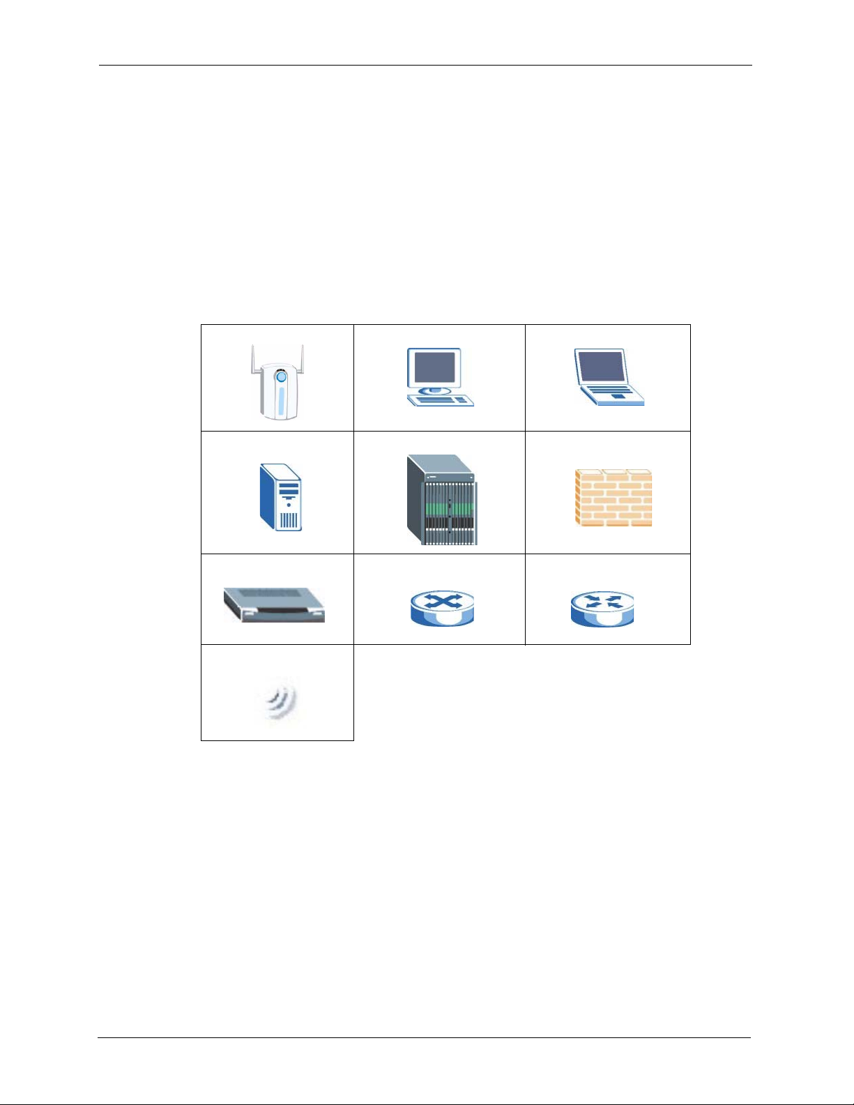
Graphics Icons Key
ZyXEL device Computer Notebook computer
Server DSLAM Firewall
Modem Switch Router
Wireless Signal
26 Preface
Page 27

CHAPTER 1
Getting to Know Your Device
This chapter introduces the main features and applications of the G-1000 v2.
1.1 Introducing the ZyXEL G-1000 v2
The ZyXEL G-2000 Plus v2 is a wireless access point. The G-1000 v2 offers highly secured
wireless connectivity to your wired network with IEEE 802.1X, WEP data encryption,
WPA(2) (Wi-Fi Protected Access) and MAC address filtering.
The G-1000 v2 is easy to install and configure. The embedded web-based configurator and
SNMP network management enables remote configuration and management of your G-1000
v2.
ZyXEL G-1000 v2 User’s Guide
1.2 Features
The following sections describe the features of the G-1000 v2.
Note: See the product specifications in the appendix for detailed features and
standards support.
1.2.1 Physical Features
10/100M Auto-negotiating Ethernet/Fast Ethernet Interface
This auto-negotiating feature allows the G-1000 v2 to detect the speed of incoming
transmissions and adjust appropriately without manual intervention. It allows data transfer of
either 10 Mbps or 100 Mbps in either half-duplex or full-duplex mode depending on your
Ethernet network.
10/100M Auto-crossover Ethernet/Fast Ethernet Interface
The LAN interface automatically adjusts to either a crossover or straight-through Ethernet
cable.
Reset Button
The G-1000 v2 reset button is built into the side panel. Use this button to restore the factory
default password to 1234; IP address to 192.168.1.2 and subnet mask to 255.255.255.0.
Chapter 1 Getting to Know Your Device 27
Page 28
ZyXEL G-1000 v2 User’s Guide
ZyAIR LED
The blue ZyAIR LED (also known as the breathing light) is on when the G-1000 v2 is on and
blinks (or breaths) when data is being transmitted to/from its wireless stations. You may use
the web configurator to turn this light off even when the G-1000 v2 is on and data is being
transmitted/received.
1.2.2 Firmware Features
WPA and WPA2
Wi-Fi Protected Access (WPA) is a subset of the IEEE 802.11i standard. WPA2 (IEEE
802.11i) is a wireless security standard that defines stronger encryption, authentication and
key management than WPA.
Key differences between WPA(2) and WEP are improved data encryption and user
authentication.
IEEE 802.11b Wireless LAN Standard
The G-1000 v2 complies with the IEEE 802.11b wireless standards.
The IEEE 802.11b data rate and corresponding modulation techniques are shown in the table
below. The modulation technique defines how bits are encoded onto radio waves.
Table 1 IEEE 802.11b
DATA RATE (MBPS) MODULATION
1 DBPSK (Differential Binary Phase Shift Keyed)
2 DQPSK (Differential Quadrature Phase Shift Keying)
5.5 / 11 CCK (Complementary Code Keying)
IEEE 802.11g Wireless LAN Standard
The G-1000 v2, complies with the IEEE 802.11g wireless standard and is also fully
compatible with the IEEE 802.11b standard. This means an IEEE 802.11b radio card can
interface directly with an IEEE 802.11g device (and vice versa) at 11 Mbps or lower
depending on range.The IEEE 802.11g has several intermediate rate steps between the
maximum and minimum data rates. The IEEE 802.11g data rate and modulation are as
follows:.
Table 2 IEEE 802.11g
DATA RATE
(MBPS)
6/9/12/18/24/36/48/54 OFDM (Orthogonal Frequency Division Multiplexing)
28 Chapter 1 Getting to Know Your Device
MODULATION
Page 29

ZyXEL G-1000 v2 User’s Guide
Note: The G-1000 v2 may be prone to RF (Radio Frequency) interference from other
2.4 GHz devices such as microwave ovens, wireless phones, Bluetooth
enabled devices, and other wireless LANs.
STP (Spanning Tree Protocol) / RSTP (Rapid STP)
(R)STP detects and breaks network loops and provides backup links between switches,
bridges or routers. It allows a bridge to interact with other (R)STP -compliant bridges in your
network to ensure that only one path exists between any two stations on the network.
Limit the number of Client Connections
You may set a maximum number of wireless stations that may connect to the G-1000 v2. This
may be necessary if for example, there is interference or difficulty with channel assignment
due to a high density of APs within a coverage area.
SSL Passthrough
SSL (Secure Sockets Layer) uses a public key to encrypt data that's transmitted over an SSL
connection. Both Netscape Navigator and Internet Explorer support SSL, and many Web sites
use the protocol to obtain confidential user information, such as credit card numbers. By
convention, URLs that require an SSL connection start with “https” instead of “http”. The G1000 v2 allows SSL connections to take place through the G-1000 v2.
Brute-Force Password Guessing Protection
The G-1000 v2 has a special protection mechanism to discourage brute-force password
guessing attacks on the G-1000 v2's management interfaces. You can specify a wait-time that
must expire before entering a fourth password after three incorrect passwords have been
entered. Please see the appendix for details about this feature.
Wireless LAN MAC Address Filtering
Your G-1000 v2 checks the MAC address of the wireless station against a list of allowed or
denied MAC addresses.
WEP Encryption
WEP (Wired Equivalent Privacy) encrypts data frames before transmitting over the wireless
network to help keep network communications private.
IEEE 802.1X Network Security
The G-1000 v2 supports the IEEE 802.1x standard to enhance user authentication. Use the
built-in user profile database to authenticate up to 32 users using MD5 encryption. Use an
EAP-compatible RADIUS (RFC2138, 2139 - Remote Authentication Dial In User Service)
server to authenticate a limitless number of users using EAP (Extensible Authentication
Protocol). EAP is an authentication protocol that supports multiple types of authentication.
Chapter 1 Getting to Know Your Device 29
Page 30

ZyXEL G-1000 v2 User’s Guide
SNMP
SNMP (Simple Network Management Protocol) is a protocol used for exchanging
management information between network devices. SNMP is a member of the TCP/IP
protocol suite. Your G-1000 v2 supports SNMP agent functionality, which allows a manager
station to manage and monitor the G-1000 v2 through the network. The G-1000 v2 supports
SNMP version one (SNMPv1) and version two c (SNMPv2c).
Full Network Management
The embedded web configurator is an all-platform web-based utility that allows you to easily
access the G-1000 v2’s management settings. Most functions of the G-1000 v2 are also
software configurable via the SMT (System Management Terminal) interface. The SMT is a
menu-driven interface that you can access from a terminal emulator over a telnet connection.
Logging and Tracing
• Built-in message logging.
• Unix syslog facility support.
Diagnostics Capabilities
The G-1000 v2 can perform self-diagnostic tests. These tests check the integrity of the
following circuitry:
• FLASH memory
•DRAM
• LAN port
• Wireless port
Embedded FTP and TFTP Servers
The G-1000 v2’s embedded FTP and TFTP servers enable fast firmware upgrades as well as
configuration file backups and restoration.
Wireless Association List
With the wireless association list, you can see the list of the wireless stations that are currently
using the G-1000 v2 to access your wired network.
1.3 Applications for the G-1000 v2
Here are application examples of what you can do with your G-1000 v2.
30 Chapter 1 Getting to Know Your Device
Page 31

1.3.1 Internet Access Application
The G-1000 is an ideal access solution for wireless Internet connection. A typical Internet
access application for your G-1000 is shown as follows. Stations A, B and C can access the
wired network through the G-1000s.
Figure 1 Internet Access Application
ZyXEL G-1000 v2 User’s Guide
1.3.2 Corporation Network Application
In situations where users are always on the move in the coverage area but still need access to
corporate network access, the G-1000 is an ideal solution for wireless stations to connect to the
corporate network without expensive network cabling.
The following figure depicts a typical application of the G-1000 in an enterprise environment.
Stations A and B with wireless adapters are allowed to access the network resource through
the G-1000 after account validation by the network authentication server.
Figure 2 Corporation Network Application
1.4 Front Panel of the G-1000
The LEDs on the front panel indicate the operational status of your G-1000.
Chapter 1 Getting to Know Your Device 31
Page 32

ZyXEL G-1000 v2 User’s Guide
Figure 3 G-1000 v2 Front Panel
The following table describes the lights.
Table 3 Front Panel Light Description
LIGHT COLOR STATUS DESCRIPTION
SYS Green On The wireless card on the G-1000 v2 is working properly.
Off The wireless card on the G-1000 v2 is not ready or has a
malfunction.
Red Blinking The G-1000 v2 is not ready or rebooting.
ZyAIR Blue Breathing The G-1000 v2 is sending or receiving data.
On (dim) The G-1000 v2 is ready, but is not sending or receiving
data.
ETHN Green On The G-1000 v2 has a successful 10Mb Ethernet
connection.
Blinking The G-1000 v2 is sending/receiving data.
Off The G-1000 v2 does not have 10Mb Ethernet connection.
Orange On The G-1000 v2 has a successful 100Mb Ethernet
connection.
Blinking The G-1000 v2 is sending or receiving data.
Off The G-1000 v2 does not have 100Mb Ethernet connection.
PWR Green On The G-1000 v2 is receiving power.
Off The G-1000 v2 is not receiving power.
32 Chapter 1 Getting to Know Your Device
Page 33

Introducing the Web
This chapter describes how to access the G-1000 v2 web configurator and provides an
overview of its screens. The default IP address of the G-1000 v2 is 192.168.1.2.
2.1 Web Configurator Overview
The embedded web configurator allows you to manage the G-1000 v2 from anywhere through
a browser such as Microsoft Internet Explorer or Netscape Navigator. Use Internet Explorer
6.0 and later or Netscape Navigator 7.0 and later versions with JavaScript enabled. It is
recommended that you set your screen resolution to 1024 by 768 pixels.
ZyXEL G-1000 v2 User’s Guide
CHAPTER 2
Configurator
2.2 Accessing the G-1000 v2 Web Configurator
1 Make sure your G-1000 v2 hardware is properly connected and prepare your computer/
computer network to connect to the G-1000 v2 (refer to the Quick Start Guide).
Launch your web browser.
2
3
Type "192.168.1.2" as the URL.
4
Type "1234" (default) as the password and click Login.
You should see a screen asking you to change your password (highly recommended) as
5
shown next. Type a new password (and retype it to confirm) and click Apply or click
Ignore.
Note: If you do not change the password, the following screen appears every time
you login.
Chapter 2 Introducing the Web Configurator 33
Page 34

ZyXEL G-1000 v2 User’s Guide
Figure 4 Change Password Screen
6 On this screen you can access the wizard setup or the advanced setup.
Click Go to Advanced setup to access the status screen of the web configurator.
Note: The management session automatically times out when the time period set in
the Administrator Inactivity Timer field expires (default five minutes). Simply log
back into the G-1000 v2 if this happens to you.
2.3 Resetting the G-1000 v2
If you forget your password or cannot access the web configurator, you will need to reload the
factory-default configuration file or use the RESET button on the top panel of the G-1000 v2.
Uploading this configuration file replaces the current configuration file with the factorydefault configuration file. This means that you will lose all configurations that you had
previously and the password will be reset to 1234.
2.3.1 .Procedure To Use The Reset Button
Make sure the SYS light is on (not blinking) before you begin this procedure.
Press the RESET button for ten seconds or until the SYS light starts to blink, and then
1
release it. If the SYS light begins to blink, the defaults have been restored and the G-1000
v2 restarts. Otherwise, go to step 2.
2
Turn the G-1000 v2 off.
While pressing the RESET button, turn the G-1000 v2 on.
3
4
Continue to hold the RESET button. The SYS light will begin to blink and flicker very
quickly after about 20 seconds. This indicates that the defaults have been restored and the
G-1000 v2 is now restarting.
5
Release the RESET button and wait for the G-1000 v2 to finish restarting.
34 Chapter 2 Introducing the Web Configurator
Page 35

Note: You can also restore defaults via the web configurator.(refer to the Maintenance
chapter).
2.4 Navigating the Web Configurator
We use the P-662HW-D1 web screens in this guide as an example. Screens vary slightly for
different G-1000 v2 models.
2.4.1 Navigation Panel
After you enter the password, use the sub-menus on the navigation panel to configure G-1000
v2 features. The following table describes the sub-menus.
Figure 5 Web Configurator: Main Screen
ZyXEL G-1000 v2 User’s Guide
Click the Logout icon at any time
Click the Logout icon at any time
to exit the web configurator.
to exit the web configurator.
Use
submenus
to configure
G-1000 v2
features.
Note: Click the icon (located in the top right corner of most screens) to view
embedded help.
Table 4 Web Configurator Screens Summary
LINK/ICON SUB-LINK FUNCTION
Wizard Use these screens for initial configuration including general
setup, wireless security and IP address assignment.
Logout Click this icon to exit the web configurator.
Chapter 2 Introducing the Web Configurator 35
Page 36

ZyXEL G-1000 v2 User’s Guide
Table 4 Web Configurator Screens Summary (continued)
LINK/ICON SUB-LINK FUNCTION
About Click this icon to see general information about G-1000 v2.
Status This screen shows the G-1000 v2’s general device, system and
Network
Wireless LAN General Use this screen to configure the wireless LAN settings and
IP Internet
Management
Remote MGMT
Maintenance
System General This screen contains administrative and system-related
Logs View Log Use this screen to view the logs for the categories that you
Tools Firmware Use this screen to upload firmware to your G-1000 v2.
interface status information. Use this screen to access the
summary statistics tables.
WLAN authentication/security settings.
MAC Filter Use this screen to configure the G-1000 v2 to block access to
devices or block the devices from accessing the G-1000 v2.
Advanced Use this screen to enable roaming and setup advanced
wireless features.
Use this screen to configure IP address assignment.
Connection
Advanced Use this screen to configure your DNS server settings.
WWW Use this screen to configure through which interface(s) and
from which IP address(es) users can use HTTPS or HTTP to
manage the G-1000 v2.
Te ln e t Use this screen to configure through which interface(s) and
from which IP address(es) users can use Telnet to manage the
G-1000 v2.
FTP Use this screen to configure through which interface(s) and
from which IP address(es) users can use FTP to access the G1000 v2.
SNMP Use this screen to configure your G-1000 v2’s settings for
Simple Network Management Protocol management.
information and also allows you to change your password.
Time Setting Use this screen to change your G-1000 v2’s time and date.
selected.
Log Settings Use this screen to change your G-1000 v2’s log settings.
Configuration Use this screen to backup and restore the configuration or reset
the factory defaults to your G-1000 v2.
Restart This screen allows you to reboot the G-1000 v2 without turning
the power off.
2.4.2 Status Screen
The following summarizes how to navigate the web configurator from the Status screen.
36 Chapter 2 Introducing the Web Configurator
Page 37

Figure 6 Status Screen
ZyXEL G-1000 v2 User’s Guide
The following table describes the labels shown in the Status screen.
Table 5 Status Screen
LABEL DESCRIPTION
Refresh Interval Select a number of seconds or None from the drop-down list box to refresh all
screen statistics automatically at the end of every time interval or to not refresh the
screen statistics.
Refresh Now Click this button to refresh the status screen statistics.
Device Information
System Name This is the System Name you enter in the Maintenance, System, General
Firmware Version This is the Firmware version and the date created.
Ethernet
Information
IP Address This is the LAN port IP address.
IP Subnet Mask This is the LAN port IP subnet mask.
DHCP This is the WAN port DHCP role - Relay or None.
WLAN Information
SSID This is the descriptive name used to identify the G-1000 v2 in the wireless LAN.
Channel This is the channel number used by the G-1000 v2 now.
Security Mode This displays the security mode you are using.
System Status
screen. It is for identification purposes.
Chapter 2 Introducing the Web Configurator 37
Page 38

ZyXEL G-1000 v2 User’s Guide
Table 5 Status Screen
LABEL DESCRIPTION
System Uptime This is the total time the G-1000 v2 has been on.
Current Date/Time This field displays your G-1000 v2’s present date and time.
System Resource
CPU Usage This number shows how many kilobytes of the heap memory the G-1000 v2 is
Memory Usage This number shows the G-1000 v2's total heap memory (in kilobytes).
Interface Status
Interface This displays the G-1000 v2 port types. The port types are Ethernet and WLAN.
Status This field displays Down (line is down), Up (line is up or connected.
Rate For the Ethernet port, this displays the port speed and duplex setting.
Summary
Packet Statistics Use this screen to view port status and packet specific statistics.
WLAN Station
Status
using. Heap memory refers to the memory that is not used by ZyNOS (ZyXEL
Network Operating System).
The bar displays what percent of the G-1000 v2's heap memory is in use. The bar
turns from green to red when the maximum is being approached.
The bar displays what percent of the G-1000 v2's heap memory is in use. The bar
turns from green to red when the maximum is being approached.
For the WAN port, it displays the downstream and upstream transmission rate.
Use this screen to view the wireless stations that are currently associated to the G1000 v2.
2.4.3 Status: Packet Statistics
To view packet statistics, click on Packet Statistics(Details...) link in the status screen under
the Summary heading.
Figure 7 Status: Packet Statistics
38 Chapter 2 Introducing the Web Configurator
Page 39

ZyXEL G-1000 v2 User’s Guide
The following table describes the labels in this screen.
Table 6 Status: Packet Statistics
LABEL DESCRIPTION
Port This is the Ethernet or wireless port. The wireless port may be the WLAN – Built-
in card or the WLAN – Removable wireless card.
Status This shows the port speed and duplex setting if you are using Ethernet
encapsulation for the Ethernet port.
This shows the transmission speed only for wireless port.
TxPkts This is the number of transmitted packets on this port.
RxPkts This is the number of received packets on this port.
Collisions This is the number of collisions on this port.
Tx B/s This shows the transmission speed in bytes per second on this port.
Rx B/s This shows the reception speed in bytes per second on this port.
Up Time This is total amount of time the line has been up.
System Up Time This is the total time the G-1000 has been on.
Poll Interval(s) Enter the time interval for refreshing statistics.
Set Interval Click this button to apply the new poll interval you entered above.
Stop Click this button to stop refreshing statistics.
2.4.4 Status: WLAN Association List
To view packet statistics, click on Packet Statistics(Details...) link in the status screen under
the Summary heading.
The following table describes the labels in this screen.
Table 7 Association List
LABEL DESCRIPTION
# This is the index number of an associated wireless station.
MAC Address This field displays the MAC address of an associated wireless station.
Association Time This field displays the time a wireless station first associated with the G-1000
v2.
Chapter 2 Introducing the Web Configurator 39
Page 40

ZyXEL G-1000 v2 User’s Guide
Table 7 Association List
LABEL DESCRIPTION
QoS This field displays the priority level of a wireless device associated with the G-
Refresh Click Refresh to reload the screen.
1000 v2
40 Chapter 2 Introducing the Web Configurator
Page 41
The web configurator’s setup wizard helps you set up a wireless LAN and configure security
settings on your G-1000 v2.
3.1 Wizard Setup Overview
The wizard will guide you through several steps. You will need to enter some information for
identification purposes, you will then setup your wireless LAN and security. The wizard will
then guide you through configuring your Internet settings.
3.2 General Setup
ZyXEL G-1000 v2 User’s Guide
CHAPTER 3
Wizard Setup
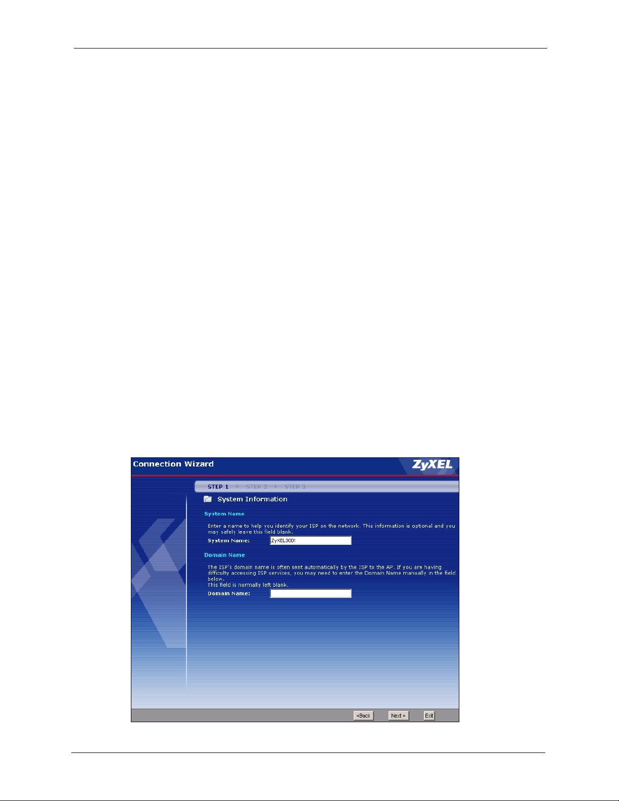
General Setup contains administrative and system-related information.
The Domain Name entry is what is propagated to the DHCP clients on the LAN. If you leave
this blank, the domain name obtained by DHCP from the ISP is used. While you must enter
the host name (System Name) on each individual computer, the domain name can be relayed
via the G-1000 v2 from the DHCP server.
Figure 8 Enter System and Domain Names.
Chapter 3 Wizard Setup 41
Page 42

ZyXEL G-1000 v2 User’s Guide
The following table describes the labels in this screen.
Table 8 Enter System and Domain Names
LABEL DESCRIPTION
System Name Enter a name to help you identify your ISP on the network. This is not a required
field and you can safely leave this field blank.
Domain Name This is not a required field. Leave this field blank or enter the domain name here
if you know it.
Back Click Back to return to the previous screen.
Next Click Next to proceed to the next screen.
Exit Click Exit to quit the wizard without saving the changes.
3.3 Wizard Setup Wireless LAN
This wizard helps you configure your wireless network and security.
3.3.1 Name (SSID), Channel ID and Security
This screen allows you to setup a unique name for your G-1000 v2 on the wireless network.
You also decide on the channel for your wireless transmission and what kind of security you
would like to use.
Figure 9 Enter Name and Select Security
42 Chapter 3 Wizard Setup
Page 43

The following table describes the labels in this screen.
Table 9 Enter Name and Select Security
LABEL DESCRIPTION
Wireless LAN Setup
ZyXEL G-1000 v2 User’s Guide
Name(SSID) Enter a descriptive name (up to 32 printable 7-bit ASCII characters) for the
Choose Channel ID To manually set the G-1000 v2 to use a specific channel, select a channel from
Security The level of Security can be selected as none, basic or extended. Choose
Back Click Back to return to the previous screen.
Next Click Next to continue.
Exit Click Exit to quit the wizard without saving the changes.
wireless LAN.
If you change this field on the G-1000 v2, make sure all wireless stations use
the same SSID in order to access the network.
the drop-down list box.
None security to have no wireless LAN security configured and proceed to the
“Apply Settings” on page 47 section.
Choose Basic (WEP) security if you want to configure WEP Encryption
parameters.
Choose Extend (WPA-PSK with customized key) or Extend (WPA2-PSK
with customized key) security to configure a Pre-Shared Key.
The next screen varies depending on which security level you select.
Note: The wireless stations and G-1000 v2 must use the same SSID, channel ID and
WEP encryption key (if WEP is enabled) or WPA-PSK (if WPA-PSK is enabled)
for wireless communication.
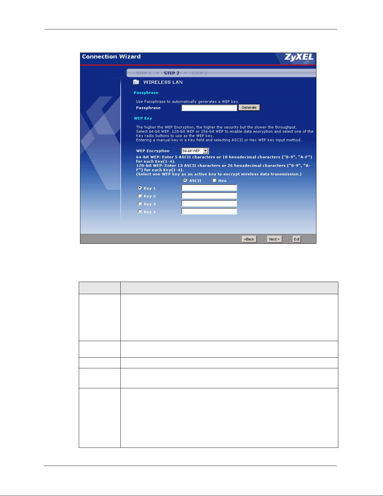
3.3.2 Configuring WEP or WPA(2) PSK Security
Choose Basic (WEP) security to setup WEP Encryption parameters.
Chapter 3 Wizard Setup 43
Page 44
ZyXEL G-1000 v2 User’s Guide
Figure 10 Wireless LAN Basic Security
The following table describes the labels in this screen.
Table 10 Wireless LAN Basic Security
LABEL DESCRIPTION
Passphrase You can generate or manually enter a WEP key by either:
Entering a Passphrase (up to 32 printable characters) and clicking Generate. The G1000 v2 automatically generates a WEP key.
Or
Entering a manual key in a Key field and selecting ASCII or Hex WEP key input
method.
WEP
Encryption
ASCII
HEX
Key 1 to Key 4 The WEP keys are used to encrypt data. Both the G-1000 v2 and the wireless stations
Select 64-bit WEP or 128-bit WEP to allow data encryption.
Select this option in order to enter ASCII characters as the WEP keys.
Select this option to enter hexadecimal characters as the WEP keys.
The preceding “0x” is entered automatically.
must use the same WEP key for data transmission.
If you chose 64-bit WEP, then enter any 5 ASCII characters or 10 hexadecimal
characters ("0-9", "A-F").
If you chose 128-bit WEP, then enter 13 ASCII characters or 26 hexadecimal
characters ("0-9", "A-F").
You must configure all four keys, but only one key can be activated at any one time.
The default key is key 1.
44 Chapter 3 Wizard Setup
Page 45

ZyXEL G-1000 v2 User’s Guide
Table 10 Wireless LAN Basic Security
LABEL DESCRIPTION
Back Click Back to display the previous screen.
Next Click Next to proceed to the next screen.
Exit Click Exit to quit the wizard without saving the changes.
Choose Extend(WPA-PSK with customized key) or Extend(WPA2-PSK with customized
security in the Wireless LAN Setup screen to set up a Pre-Shared Key.
key)
Figure 11 Wireless LAN Extend Security
The following table describes the labels in this screen.
Table 11 Wireless LAN Extend Security
LABEL DESCRIPTION
Pre-Shared
Key
Back Click Back to display the previous screen.
Next Click Next to proceed to the next screen.
Exit Click Exit to quit the wizard without saving the changes.
Type from 8 to 63 case-sensitive ASCII characters. You can set up the most secure
wireless connection by configuring WPA in the advanced wireless screen. You need to
configure an authentication server to do this.
Refer to the chapter on wireless LAN for more information.
Chapter 3 Wizard Setup 45
Page 46

ZyXEL G-1000 v2 User’s Guide
3.3.3 IP Address Assignment
Your G-1000 v2 needs an IP address to communicate with your wired network.
Figure 12 IP Address Assignment
The following table describes the labels in this screen.
Table 12 IP Address Assignment
LABEL DESCRIPTION
Obtain IP
Address
Automatically
Use fixed IP
address
Back Click Back to display the previous screen.
Next Click Next to proceed to the next screen.
Exit Click Exit to quit the wizard without saving the changes.
Select this choice if your G-1000 v2 is using a dynamically assigned IP address from a
DHCP server.
Select this choice if your G-1000 v2 is using a static IP address.
Note: If you change the IP address assigned to the G-1000 v2 or if a DHCP server
assigns a new one to it, you must know it to access the G-1000 again.
46 Chapter 3 Wizard Setup
Page 47

3.3.4 Apply Settings
If you changed the SSID on your device or implemented any security, then you will have to
make the corresponding changes on your wireless station to reconnect to the G-1000 v2.
ZyXEL G-1000 v2 User’s Guide
The following table describes the labels in this screen.
Table 13 Apply Settings
LABEL DESCRIPTION
Back Click Back to display the previous screen.
Apply Click Apply to save your configuration settings.
Exit Click Exit to quit the wizard without saving the changes.
Note: If you changed the SSID on your device or implemented any security, then you
will have to make the corresponding changes on your wireless stations to
reconnect to the AP.
If you changed the IP address of your G-1000 v2 or if an IP address is assigned
to the G-1000 v2 automatically, you can access the device by using the new IP
address or typing “http://zyxelXXXX” (where XXXX are the last four digits of
your devices MAC address) in your browser. The MAC address can be found
on the back label of your G-1000 v2.
Congratulations, you have completed your configuration wizard. Click Finish to exit the
wizard.
Chapter 3 Wizard Setup 47
Page 48

ZyXEL G-1000 v2 User’s Guide
Figure 13 Wizard Completed
48 Chapter 3 Wizard Setup
Page 49

This chapter discusses how to configure the wireless network settings in your G-1000 v2. See
the appendices for more detailed information about wireless networks.
4.1 Wireless Network Overview
The following figure provides an example of a wireless network.
Figure 14 Example of a Wireless Network
ZyXEL G-1000 v2 User’s Guide
CHAPTER 4
Wireless LAN
The wireless network is the part in the blue circle. In this wireless network, devices A and B
are called wireless clients. The wireless clients use the access point (AP) to interact with other
devices (such as the printer) or with the Internet. Your G-1000 v2 is the AP.
Every wireless network must follow these basic guidelines.
• Every wireless client in the same wireless network must use the same SSID.
The SSID is the name of the wireless network. It stands for Service Set IDentity.
• If two wireless networks overlap, they should use different channels.
Like radio stations or television channels, each wireless network uses a specific channel,
or frequency, to send and receive information.
• Every wireless client in the same wireless network must use security compatible with the
AP.
Chapter 4 Wireless LAN 49
Page 50

ZyXEL G-1000 v2 User’s Guide
Security stops unauthorized devices from using the wireless network. It can also protect
the information that is sent in the wireless network.
4.2 Wireless Security Overview
The following sections introduce different types of wireless security you can set up in the
wireless network.
4.2.1 SSID
Normally, the AP acts like a beacon and regularly broadcasts the SSID in the area. You can
hide the SSID instead, in which case the AP does not broadcast the SSID. In addition, you
should change the default SSID to something that is difficult to guess.
This type of security is fairly weak, however, because there are ways for unauthorized devices
to get the SSID. In addition, unauthorized devices can still see the information that is sent in
the wireless network.
4.2.2 MAC Address Filter
Every wireless client has a unique identification number, called a MAC address.1 A MAC
address is usually written using twelve hexadecimal characters
or 00:A0:C5:00:00:02. To get the MAC address for each wireless client, see the appropriate
User’s Guide or other documentation.
You can use the MAC address filter to tell the AP which wireless clients are allowed or not
allowed to use the wireless network. If a wireless client is allowed to use the wireless network,
it still has to have the correct settings (SSID, channel, and security). If a wireless client is not
allowed to use the wireless network, it does not matter if it has the correct settings.
This type of security does not protect the information that is sent in the wireless network.
Furthermore, there are ways for unauthorized devices to get the MAC address of an authorized
wireless client. Then, they can use that MAC address to use the wireless network.
4.2.3 User Authentication
You can make every user log in to the wireless network before they can use it. This is called
user authentication. However, every wireless client in the wireless network has to support
IEEE 802.1x to do this.
2
; for example, 00A0C5000002
For wireless networks, there are two typical places to store the user names and passwords for
each user.
1. Some wireless devices, such as scanners, can detect wireless networks but cannot use wireless
networks. These kinds of wireless devices might not have MAC addresses.
2. Hexadecimal characters are 0, 1, 2, 3, 4, 5, 6, 7, 8, 9, A, B, C, D, E, and F.
50 Chapter 4 Wireless LAN
Page 51

• In the AP: this feature is called a local user database or a local database.
• In a RADIUS server: this is a server used in businesses more than in homes.
If your AP does not provide a local user database and if you do not have a RADIUS server,
you cannot set up user names and passwords for your users.
Unauthorized devices can still see the information that is sent in the wireless network, even if
they cannot use the wireless network. Furthermore, there are ways for unauthorized wireless
users to get a valid user name and password. Then, they can use that user name and password
to use the wireless network.
Local user databases also have an additional limitation that is explained in the next section.
4.2.4 Encryption
Wireless networks can use encryption to protect the information that is sent in the wireless
network. Encryption is like a secret code. If you do not know the secret code, you cannot
understand the message.
ZyXEL G-1000 v2 User’s Guide
The types of encryption you can choose depend on the type of authentication. (See Section
4.2.3 on page 50 for information about this.)
Table 14 Types of Encryption for Each Type of Authentication
No Authentication RADIUS Server
Weakest None IEEE 802.1x
Static WEP IEEE 802.1x + Static WEP
WPA-PSK WPA
Strongest WPA2-PSK WPA2
For example, if the wireless network has a RADIUS server, you can choose IEEE 802.1x,
IEEE 802.1x + Static WEP, IEEE 802.1x + Dynamic WEP, WPA or WPA2. If users do not
log in to the wireless network, you can choose no encryption, Static WEP, WPA-PSK, or
WPA2-PSK.
Usually, you should set up the strongest encryption that every device in the wireless network
supports. For example, suppose you have a wireless network with the G-1000 v2. The G-1000
v2 does not have a local user database, and you do not have a RADIUS server. Therefore,
there is no authentication. Suppose the wireless network has two devices. Device A only
supports WEP, and device B supports WEP and WPA. Therefore, you should set up Static
WEP in the wireless network.
Chapter 4 Wireless LAN 51
Page 52

ZyXEL G-1000 v2 User’s Guide
Note: It is recommended that wireless networks use WPA-PSK, WPA, or stronger
encryption. IEEE 802.1x and WEP encryption are better than none at all, but it
is still possible for unauthorized wireless devices to figure out the original
information pretty quickly.
It is not possible to use WPA-PSK, WPA or stronger encryption with a local
user database. In this case, it is better to set up stronger encryption with no
authentication than to set up weaker encryption with the local user database.
When you select WPA2 or WPA2-PSK in your G-1000 v2, you can also select an option
(WPA compatible) to support WPA as well. In this case, if some of the devices support WPA
and some support WPA2, you should set up WPA2-PSK or WPA2 (depending on the type of
wireless network login) and select the WPA compatible option in the G-1000 v2.
Many types of encryption use a key to protect the information in the wireless network. The
longer the key, the stronger the encryption. Every device in the wireless network must have
the same key.
4.3 Additional Wireless Terms
The following table describes wireless network terms and acronyms used in the G-1000 v2.
Table 15 Additional Wireless Terms
TERM DESCRIPTION
Intra-BSS Traffic This describes communication (through the AP) between two wireless clients
within a wireless network. You might disable this kind of communication to
enhance security within your wireless network.
RTS/CTS Threshold In a wireless network which covers a large area, wireless clients are
sometimes not aware of each other’s presence. This may cause them to send
information to the AP at the same time and result in information colliding and
not getting through.
By setting this value lower than the default value, the wireless clients must
sometimes get permission to send information to the AP. The lower the value,
the more often the wireless clients must get permission.
If this value is greater than the fragmentation threshold value (see below), then
wireless clients never have to get permission to send information to the AP.
Preamble A preamble affects the timing in your wireless network. There are two
preamble modes: long and short. Most wireless clients can detect the AP’s
preamble automatically. However, if a wireless client tries to use a different
preamble mode than the AP does, it cannot communicate with the AP.
Max. Frame Burst Enable this to improve the performance of pure IEEE 802.11g and mixed IEEE
802.11b/g networks. In pure IEEE 802.11g networks, set this to the maximum
value. In mixed networks, the higher the value, the higher the priority of IEEE
802.11g traffic.
Fragmentation
Threshold
Roaming If you have two or more APs on your wireless network, you can enable this
A small fragmentation threshold is recommended for busy networks, while a
larger threshold provides faster performance if the network is not very busy.
option so that wireless clients can change locations without having to log in
again. This is useful for wireless clients, such as notebooks, that move around
a lot.
52 Chapter 4 Wireless LAN
Page 53

4.4 Wireless LAN Screen
Note: If you are configuring the G-1000 v2 from a computer connected to the wireless
LAN and you change the G-1000 v2’s SSID or WEP settings, you will lose your
wireless connection when you press Apply to confirm. You must then change
the wireless settings of your computer to match the G-1000 v2’s new settings.
Click Network > Wireless LAN to open the General screen.
Figure 15 Wireless LAN: General
ZyXEL G-1000 v2 User’s Guide
The following table describes the general wireless LAN labels in this screen.
Table 16 Wireless LAN: General
LABEL DESCRIPTION
Wireless Setup
Name(SSID) (Service Set IDentity) The SSID identifies the Service Set with which a wireless
station is associated. Wireless stations associating to the access point (AP) must
have the same SSID. Enter a descriptive name (up to 32 printable 7-bit ASCII
characters) for the wireless LAN.
Note: If you are configuring the G-1000 v2 from a computer
connected to the wireless LAN and you change the G-1000 v2’s
SSID or WEP settings, you will lose your wireless connection
when you press Apply to confirm. You must then change the
wireless settings of your computer to match the G-1000 v2’s
new settings.
Hide SSID Select this check box to hide the SSID in the outgoing beacon frame so a station
cannot obtain the SSID through scanning using a site survey tool.
Channel
Selection
Security See the rest of this chapter for information on the other labels in this screen.
Set the operating frequency/channel depending on your particular region.
Select a channel from the drop-down list box.
Chapter 4 Wireless LAN 53
Page 54

ZyXEL G-1000 v2 User’s Guide
Table 16 Wireless LAN: General
LABEL DESCRIPTION
Apply Click Apply to save your changes back to the G-1000 v2.
Reset Click Reset to reload the previous configuration for this screen.
See the rest of this chapter for information on the other labels in this screen.
4.4.1 No Security
Select No Security to allow wireless stations to communicate with the access points without
any data encryption.
Note: If you do not enable any wireless security on your G-1000 v2, your network is
accessible to any wireless networking device that is within range.
Figure 16 Wireless: No Security
The following table describes the labels in this screen.
Table 17 Wireless No Security
LABEL DESCRIPTION
Security Mode Choose No Security from the drop-down list box.
Apply Click Apply to save your changes back to the G-1000 v2.
Cancel Click Cancel to reload the previous configuration for this screen.
54 Chapter 4 Wireless LAN
Page 55

4.4.2 WEP Encryption
WEP encryption scrambles the data transmitted between the wireless stations and the access
points to keep network communications private. It encrypts unicast and multicast
communications in a network. Both the wireless stations and the access points must use the
same WEP key.
Your G-1000 v2 allows you to configure up to four 64-bit, 128-bit or 256-bit WEP keys but
only one key can be enabled at any one time.
4.4.3 WEP Encryption Screen
In order to configure and enable WEP encryption; click Network > Wireless LAN to display
the General screen. Select Static WEP from the Security Mode list.
Figure 17 Wireless: Static WEP Encryption
ZyXEL G-1000 v2 User’s Guide
Chapter 4 Wireless LAN 55
Page 56

ZyXEL G-1000 v2 User’s Guide
The following table describes the wireless LAN security labels in this screen.
Table 18 Wireless: Static WEP Encryption
LABEL DESCRIPTION
Security Mode Choose Static WEP from the drop-down list box.
Passphrase You can generate or manually enter a WEP key by either:
Entering a Passphrase (up to 32 printable characters) and clicking Generate. The G1000 v2 automatically generates a WEP key.
Or
Entering a manual key in a Key field and selecting ASCII or Hex WEP key input
method.
WEP
Encryption
Authentication
Method
ASCII
HEX
Key 1 to Key 4 The WEP keys are used to encrypt data. Both the G-1000 v2 and the wireless stations
WEP
Encryption
WEP Key The WEP keys are used to encrypt data. Both the G-1000 v2 and the wireless stations
Apply Click Apply to save your changes back to the G-1000 v2.
Reset Click Reset to reload the previous configuration for this screen.
Select 64-bit WEP, 128-bit WEP or 256-bit WEP to allow data encryption.
Select Auto, Open System or Shared Key.
Select this option in order to enter ASCII characters as the WEP keys.
Select this option to enter hexadecimal characters as the WEP keys.
The preceding “0x” is entered automatically.
must use the same WEP key for data transmission.
If you chose 64-bit WEP, then enter any 5 ASCII characters or 10 hexadecimal
characters ("0-9", "A-F").
If you chose 128-bit WEP, then enter 13 ASCII characters or 26 hexadecimal
characters ("0-9", "A-F").
If you chose 256-bit WEP, then enter 29 ASCII characters or 58 hexadecimal
characters ("0-9", "A-F").
You must configure all four keys, but only one key can be activated at any one time.
The default key is key 1.
must use the same WEP key for data transmission.
If you want to manually set the WEP key, enter any 5, 13 or 29 characters (ASCII
string) or 10, 26 or 58 hexadecimal characters ("0-9", "A-F") for a 64-bit, 128-bit or
256-bit WEP key respectively.
4.4.4 WPA(2)-PSK
In order to configure and enable WPA(2)-PSK authentication; click Network > Wireless
LAN to display the General screen. Select WPA-PSK or WPA2-PSK from the Security
Mode list.
56 Chapter 4 Wireless LAN
Page 57

Figure 18 Wireless: WPA(2)-PSK
ZyXEL G-1000 v2 User’s Guide
The following table describes the wireless LAN security labels in this screen.
Table 19 Wireless: WPA(2)-PSK
LABEL DESCRIPTION
Security Mode Choose WPA-PSK or WPA2-PSK from the drop-down list box.
WPA Compatible This check box is available only when you select WPA2-PSK or WPA2 in the
Pre-Shared Key The encryption mechanisms used for WPA(2) and WPA(2)-PSK are the same.
ReAuthentication
Timer (In
Seconds)
Security Mode field.
Select the check box to have both WPA2 and WPA wireless clients be able to
communicate with the G-1000 v2 even when the G-1000 v2 is using WPA2-PSK or
WPA2.
The only difference between the two is that WPA(2)-PSK uses a simple common
password, instead of user-specific credentials.
Type a pre-shared key from 8 to 63 case-sensitive ASCII characters (including
spaces and symbols).
Specify how often wireless stations have to resend usernames and passwords in
order to stay connected. Enter a time interval between 10 and 9999 seconds. The
default time interval is 1800 seconds (30 minutes).
Note: If wireless station authentication is done using a RADIUS
server, the reauthentication timer on the RADIUS server has
priority.
Idle Timeout (In
Seconds)
The G-1000 v2 automatically disconnects a wireless station from the wired network
after a period of inactivity. The wireless station needs to enter the username and
password again before access to the wired network is allowed. The default time
interval is 3600 seconds (or 1 hour).
Chapter 4 Wireless LAN 57
Page 58

ZyXEL G-1000 v2 User’s Guide
Table 19 Wireless: WPA(2)-PSK
LABEL DESCRIPTION
Group Key Update
Timer (In
Seconds)
Apply Click Apply to save your changes back to the G-1000 v2.
Reset Click Reset to reload the previous configuration for this screen.
The Group Key Update Timer is the rate at which the AP (if using WPA(2)-PSK
key management) or RADIUS server (if using WPA(2) key management) sends a
new group key out to all clients. The re-keying process is the WPA(2) equivalent of
automatically changing the WEP key for an AP and all stations in a WLAN on a
periodic basis. Setting of the Group Key Update Timer is also supported in
WPA(2)-PSK mode. The G-1000 v2 default is 1800 seconds (30 minutes).
4.4.5 WPA(2) Authentication Screen
In order to configure and enable WPA(2) Authentication; click the Wireless LAN link under
Network to display the Wireless screen. Select WPA or WPA2 from the Security Mode list.
Figure 19 Wireless: WPA(2)
58 Chapter 4 Wireless LAN
Page 59

ZyXEL G-1000 v2 User’s Guide
The following table describes the wireless LAN security labels in this screen.
Table 20 Wireless: WPA(2)
LABEL DESCRIPTION
WPA Compatible This check box is available only when you select WPA2-PSK or WPA2 in the
Security Mode field.
Select the check box to have both WPA2 and WPA wireless clients be able to
communicate with the G-1000 v2 even when the G-1000 v2 is using WPA2-PSK
or WPA2.
ReAuthentication
Timer (In Seconds)
Specify how often wireless stations have to resend usernames and passwords in
order to stay connected. Enter a time interval between 10 and 9999 seconds. The
default time interval is 1800 seconds (30 minutes).
Note: If wireless station authentication is done using a RADIUS
server, the reauthentication timer on the RADIUS server
has priority.
Idle Timeout (In
Seconds)
Group Key Update
Timer (In Seconds)
Authentication Server
IP Address Enter the IP address of the external authentication server in dotted decimal
Port Number Enter the port number of the external authentication server. The default port
Shared Secret Enter a password (up to 31 alphanumeric characters) as the key to be shared
Accounting Server (optional)
Active Select Yes from the drop down list box to enable user accounting through an
IP Address Enter the IP address of the external accounting server in dotted decimal notation.
Port Number Enter the port number of the external accounting server. The default port number
Shared Secret Enter a password (up to 31 alphanumeric characters) as the key to be shared
Apply Click Apply to save your changes back to the G-1000 v2.
Reset Click Reset to reload the previous configuration for this screen.
The G-1000 v2 automatically disconnects a wireless station from the wired
network after a period of inactivity. The wireless station needs to enter the
username and password again before access to the wired network is allowed.
The default time interval is 3600 seconds (or 1 hour).
The Group Key Update Timer is the rate at which the AP (if using WPA(2)-PSK
key management) or RADIUS server (if using WPA(2) key management) sends a
new group key out to all clients. The re-keying process is the WPA(2) equivalent
of automatically changing the WEP key for an AP and all stations in a WLAN on a
periodic basis. Setting of the Group Key Update Timer is also supported in
WPA(2)-PSK mode. The G-1000 v2 default is 1800 seconds (30 minutes).
notation.
number is 1812.
You need not change this value unless your network administrator instructs you
to do so with additional information.
between the external authentication server and the G-1000 v2.
The key must be the same on the external authentication server and your G-1000
v2. The key is not sent over the network.
external authentication server.
is 1813.
You need not change this value unless your network administrator instructs you
to do so with additional information.
between the external accounting server and the G-1000 v2.
The key must be the same on the external accounting server and your G-1000
v2. The key is not sent over the network.
Chapter 4 Wireless LAN 59
Page 60

ZyXEL G-1000 v2 User’s Guide
4.5 MAC Filter
The MAC filter screen allows you to configure the G-1000 v2 to give exclusive access to up to
32 devices (Allow) or exclude up to 32 devices from accessing the G-1000 v2 (Deny). Every
Ethernet device has a unique MAC (Media Access Control) address. The MAC address is
assigned at the factory and consists of six pairs of hexadecimal characters, for example,
00:A0:C5:00:00:02. You need to know the MAC address of the devices to configure this
screen.
To change your G-1000 v2’s MAC filter settings, click Network > Wireless LAN > MAC
Filter. The screen appears as shown.
Figure 20 MAC Address Filter
60 Chapter 4 Wireless LAN
Page 61

ZyXEL G-1000 v2 User’s Guide
The following table describes the labels in this menu.
Table 21 MAC Address Filter
LABEL DESCRIPTION
Active Select the check box to enable MAC address filtering.
Filter Action
Set
MAC Address
Apply Click Apply to save your changes back to the G-1000 v2.
Reset Click Reset to reload the previous configuration for this screen.
Define the filter action for the list of MAC addresses in the MAC Address table.
Select Deny to block access to the G-1000 v2, MAC addresses not listed will be
allowed to access the G-1000 v2
Select Allow to permit access to the G-1000 v2, MAC addresses not listed will be
denied access to the G-1000 v2.
This is the index number of the MAC address.
Enter the MAC addresses of the wireless station that are allowed or denied access to
the G-1000 v2 in these address fields. Enter the MAC addresses in a valid MAC
address format, that is, six hexadecimal character pairs, for example,
12:34:56:78:9a:bc.
4.6 Wireless LAN Advanced Setup
To configure advanced wireless settings, click Network > Wireless LAN > Advanced. The
screen appears as shown.
Figure 21 Wireless LAN: Advanced
Chapter 4 Wireless LAN 61
Page 62

ZyXEL G-1000 v2 User’s Guide
The following table describes the labels in this screen.
Table 22 Wireless LAN: Advanced
LABEL DESCRIPTION
Roaming Configuration
Enable
Roaming
Select this checkbox to enable roaming on the G-1000 v2 if you have two or more G1000 v2s on the same subnet.
Note: All APs on the same subnet and the wireless stations must
Port Enter the port number to communicate roaming information between APs. The port
number must be the same on all APs. The default is 3517. Make sure this port is not
used by other services.
Wireless Advanced Setup
RTS/CTS
Threshold
Fragmentation
Threshold
Enable IntraBSS Traffic
Enable
Breathing LED
Number of
Wireless
Stations
Allowed
802.11 Mode Select 802.11b Only to allow only IEEE 802.11b compliant WLAN devices to
Apply Click Apply to save your changes back to the G-1000 v2.
Reset Click Reset to reload the previous configuration for this screen.
Enter a value between 0 and 2432. If you select the Enable 802.11g+ mode
checkbox, this field is grayed out and the G-1000 v2 uses 4096 automatically.
It is the maximum data fragment size that can be sent. Enter a value between 256 and
2432. If you select the Enable 802.11g+ mode checkbox, this field is grayed out and
the G-1000 v2 uses 4096 automatically.
Intra-BSS traffic is traffic between wireless stations in the BSS (Basic Service Set).
Select this check box to enable Intra-BSS Traffic.
Select this check box to enable the Breathing LED, also known as the ZyAIR LED.
The blue ZyAIR LED is on when the G-1000 v2 is on and blinks (or breaths) when
data is being transmitted to/from its wireless stations.
Clear the check box to turn this LED off even when the G-1000 v2 is on and data is
being transmitted/received.
Enter a number from 1 to 32, to limit the number of wireless devices which can
communicate in your wireless network.
associate with the G-1000 v2.
Select 802.11g Only to allow only IEEE 802.11g compliant WLAN devices to
associate with the G-1000 v2.
Select Mixed to allow either IEEE802.11b or IEEE802.11g compliant WLAN devices
to associate with the G-1000 v2. The transmission rate of your G-1000 v2 might be
reduced.
have the same SSID to allow roaming.
62 Chapter 4 Wireless LAN
Page 63

This chapter describes how to configure your G-1000 v2 to interact with the wired network.
5.1 Configuring IP
To configure Internet connection, click Network > IP > Internet Connection. The screen
appears as shown.
Figure 22 Network: Internet Connection
ZyXEL G-1000 v2 User’s Guide
CHAPTER 5
IP and DNS Screens
The following table describes the labels in this screen.
Table 23 Network: Internet Connection
LABEL DESCRIPTION
IP Address Assignment
Get
automatically
from
DHCP
Use fixed IP
address
Chapter 5 IP and DNS Screens 63
Select this option if your G-1000 v2 is using a dynamically assigned IP address
from a DHCP server each time.
Note: If you change the IP address of your G-1000 v2 or if an IP
address is assigned to the G-1000 v2 automatically, you can
access the device by using the new IP address or typing
“http://zyxelXXXX” (where XXXX are the last four digits of your
device’s MAC address) in your browser. The MAC address can
be found on the back label of your G-1000 v2.
Select this option if your G-1000 v2 is using a static IP address. When you select
this option, fill in the fields below.
Page 64
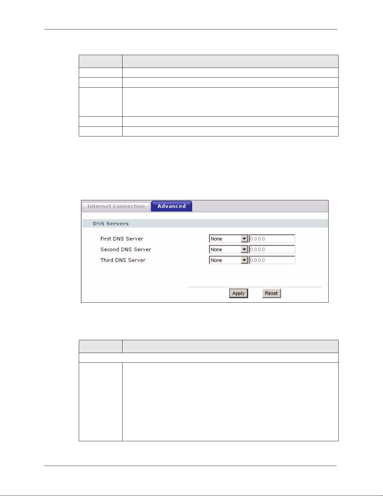
ZyXEL G-1000 v2 User’s Guide
Table 23 Network: Internet Connection
LABEL DESCRIPTION
IP Address Enter the IP address of your G-1000 v2 in dotted decimal notation.
IP Subnet Mask Type the subnet mask.
Gateway IP
Address
Apply Click Apply to save your changes back to the G-1000 v2.
Reset Click Reset to reload the previous configuration for this screen.
Type the IP address of the gateway. The gateway is an immediate neighbor of your
G-1000 v2 that will forward the packet to the destination. On the LAN, the gateway
must be a router on the same segment as your G-1000 v2; over the WAN, the
gateway must be the IP address of one of the remote nodes.
5.2 Configuring DNS
To configure DNS settings, click Network > IP > Advanced. The screen appears as shown.
Figure 23 Network: Advanced
The following table describes the labels in this screen.
Table 24 Network: Advanced
LABEL DESCRIPTION
DNS Servers
First DNS
Server
Second DNS
Server
Third DNS
Server
64 Chapter 5 IP and DNS Screens
Select From ISP if your DHCP server dynamically assigns DNS server information
(and the G-1000 v2's Ethernet IP address). The field to the right displays the (readonly) DNS server IP address that the DHCP assigns.
Select User-Defined if you have the IP address of a DNS server. Enter the DNS
server's IP address in the field to the right. If you chose User-Defined, but leave the
IP address set to 0.0.0.0, User-Defined changes to None after you click Apply. If you
set a second choice to User-Defined, and enter the same IP address, the second
User-Defined changes to None after you click Apply.
Select None if you do not want to configure DNS servers. If you do not configure a
DNS server, you must know the IP address of a machine in order to access it.
The default setting is None.
Page 65

ZyXEL G-1000 v2 User’s Guide
Table 24 Network: Advanced
LABEL DESCRIPTION
Apply Click Apply to save your changes back to the G-1000 v2.
Reset Click Reset to reload the previous configuration for this screen.
Chapter 5 IP and DNS Screens 65
Page 66

ZyXEL G-1000 v2 User’s Guide
66 Chapter 5 IP and DNS Screens
Page 67

CHAPTER 6
Remote Management
This chapter provides information on configuring remote management.
6.1 Remote Management Overview
Remote management allows you to determine which services/protocols can access which G1000 v2 interface (if any) from which computers.
Note: When you configure remote management to allow management from the WAN,
you still need to configure a firewall rule to allow access.
ZyXEL G-1000 v2 User’s Guide
Configuration
You may manage your G-1000 v2 from a remote location via:
• Internet (WAN only)
• ALL (LAN and WAN)
• LAN only,
• Neither (Disable).
Note: When you choose WAN only or LAN & WAN, you still need to configure a
firewall rule to allow access.
To disable remote management of a service, select Disable in the corresponding Access
Status field.
You may only have one remote management session running at a time. The G-1000 v2
automatically disconnects a remote management session of lower priority when another
remote management session of higher priority starts. The priorities for the different types of
remote management sessions are as follows.
1 Telnet
2 HTTP
6.1.1 Remote Management Limitations
Remote management over LAN or WAN will not work when:
• You have disabled that service in one of the remote management screens.
Chapter 6 Remote Management Configuration 67
Page 68

ZyXEL G-1000 v2 User’s Guide
• The IP address in the Secured Client IP field does not match the client IP address. If it
does not match, the G-1000 v2 will disconnect the session immediately.
• There is already another remote management session with an equal or higher priority
running. You may only have one remote management session running at one time.
• There is a firewall rule that blocks it.
6.1.2 System Timeout
There is a default system management idle timeout of five minutes (three hundred seconds).
The G-1000 v2 automatically logs you out if the management session remains idle for longer
than this timeout period. The management session does not time out when a statistics screen is
polling.
6.2 WWW
To change your G-1000 v2’s World Wide Web settings, click Advanced > Remote MGMT
to display the WWW screen.
Figure 24 Remote Management: WWW
The following table describes the labels in this screen.
Table 25 Remote Management: WWW
LABEL DESCRIPTION
Port You may change the server port number for a service if needed, however you must
use the same port number in order to use that service for remote management.
Server Access Select the interface(s) through which a computer may access the G-1000 v2 using
Secured Client IP
Address
this service.
A secured client is a “trusted” computer that is allowed to communicate with the G1000 v2 using this service.
Select All to allow any computer to access the G-1000 v2 using this service.
Choose Selected to just allow the computer with the IP address that you specify to
access the G-1000 v2 using this service.
68 Chapter 6 Remote Management Configuration
Page 69

Table 25 Remote Management: WWW
LABEL DESCRIPTION
Apply Click Apply to save your settings back to the G-1000 v2.
Cancel Click Cancel to begin configuring this screen afresh.
6.3 Telnet
You can configure your G-1000 v2 for remote Telnet access as shown next. The administrator
uses Telnet from a computer on a remote network to access the G-1000 v2.
Figure 25 Telnet Configuration on a TCP/IP Network
ZyXEL G-1000 v2 User’s Guide
6.4 Configuring Telnet
Click Advanced > Remote MGMT > Tel ne t tab to display the screen as shown.
Chapter 6 Remote Management Configuration 69
Page 70
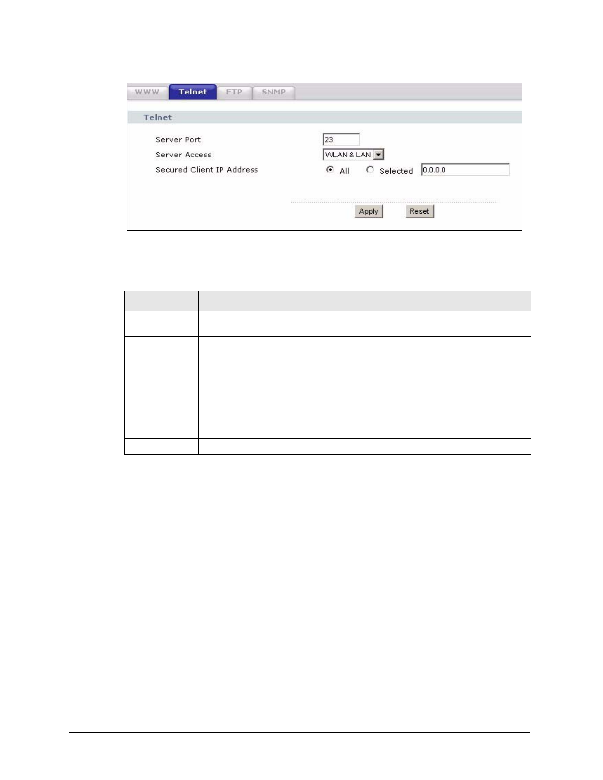
ZyXEL G-1000 v2 User’s Guide
Figure 26 Remote Management: Telnet
The following table describes the labels in this screen.
Table 26 Remote Management: Telnet
LABEL
Port You may change the server port number for a service if needed, however you must
Server Access Select the interface(s) through which a computer may access the G-1000 v2 using
Secured Client IP
Address
Apply Click Apply to save your customized settings and exit this screen.
Cancel Click Cancel to begin configuring this screen afresh.
use the same port number in order to use that service for remote management.
this service.
A secured client is a “trusted” computer that is allowed to communicate with the G1000 v2 using this service.
Select All to allow any computer to access the G-1000 v2 using this service.
Choose Selected to just allow the computer with the IP address that you specify to
access the G-1000 v2 using this service.
6.5 Configuring FTP
You can upload and download the G-1000 v2’s firmware and configuration files using FTP,
please see the chapter on firmware and configuration file maintenance for details. To use this
feature, your computer must have an FTP client.
To change your G-1000 v2’s FTP settings, click Advanced > Remote MGMT > FTP tab.
The screen appears as shown.
DESCRIPTION
70 Chapter 6 Remote Management Configuration
Page 71

Figure 27 Remote Management: FTP
The following table describes the labels in this screen.
Table 27 Remote Management: FTP
LABEL DESCRIPTION
ZyXEL G-1000 v2 User’s Guide
Port You may change the server port number for a service if needed, however you must
Server Access Select the interface(s) through which a computer may access the G-1000 v2 using
Secured Client IP
Address
Apply Click Apply to save your customized settings and exit this screen.
Cancel Click Cancel to begin configuring this screen afresh.
6.6 SNMP
Simple Network Management Protocol (SNMP) is a protocol used for exchanging
management information between network devices. SNMP is a member of the TCP/IP
protocol suite. Your G-1000 v2 supports SNMP agent functionality, which allows a manager
station to manage and monitor the G-1000 v2 through the network. The G-1000 v2 supports
SNMP version one (SNMPv1) and version two (SNMPv2). The next figure illustrates an
SNMP management operation.
use the same port number in order to use that service for remote management.
this service.
A secured client is a “trusted” computer that is allowed to communicate with the G1000 v2 using this service.
Select All to allow any computer to access the G-1000 v2 using this service.
Choose Selected to just allow the computer with the IP address that you specify to
access the G-1000 v2 using this service.
Note: SNMP is only available if TCP/IP is configured.
Chapter 6 Remote Management Configuration 71
Page 72

ZyXEL G-1000 v2 User’s Guide
Figure 28 SNMP Management Model
An SNMP managed network consists of two main types of component: agents and a manager.
An agent is a management software module that resides in a managed device (the G-1000 v2).
An agent translates the local management information from the managed device into a form
compatible with SNMP. The manager is the console through which network administrators
perform network management functions. It executes applications that control and monitor
managed devices.
The managed devices contain object variables/managed objects that define each piece of
information to be collected about a device. Examples of variables include such as number of
packets received, node port status etc. A Management Information Base (MIB) is a collection
of managed objects. SNMP allows a manager and agents to communicate for the purpose of
accessing these objects.
SNMP itself is a simple request/response protocol based on the manager/agent model. The
manager issues a request and the agent returns responses using the following protocol
operations:
• Get - Allows the manager to retrieve an object variable from the agent.
• GetNext - Allows the manager to retrieve the next object variable from a table or list
within an agent. In SNMPv1, when a manager wants to retrieve all elements of a table
from an agent, it initiates a Get operation, followed by a series of GetNext operations.
• Set - Allows the manager to set values for object variables within an agent.
• Trap - Used by the agent to inform the manager of some events.
6.6.1 Supported MIBs
The G-1000 v2 supports MIB II that is defined in RFC-1213 and RFC-1215. The focus of the
MIBs is to let administrators collect statistical data and monitor status and performance.
72 Chapter 6 Remote Management Configuration
Page 73

6.6.2 SNMP Traps
The G-1000 v2 will send traps to the SNMP manager when any one of the following events
occurs:
Table 28 SNMP Traps
ZyXEL G-1000 v2 User’s Guide
TRAP #
0 coldStart (defined in RFC-1215) A trap is sent after booting (power on).
1 warmStart (defined in RFC-1215) A trap is sent after booting (software reboot).
6 whyReboot (defined in ZYXEL-
6a For intentional reboot: A trap is sent with the message "System reboot by
6b For fatal error: A trap is sent with the message of the fatal code if the
TRAP NAME DESCRIPTION
MIB)
6.6.3 Configuring SNMP
To change your G-1000 v2’s SNMP settings, click Advanced > Remote MGMT > SNMP.
The screen appears as shown.
A trap is sent with the reason of restart before
rebooting when the system is going to restart (warm
start).
user!" if reboot is done intentionally, (for example,
download new files, CI command "sys reboot", etc.).
system reboots because of fatal errors.
Chapter 6 Remote Management Configuration 73
Page 74

ZyXEL G-1000 v2 User’s Guide
Figure 29 Remote Management: SNMP
The following table describes the labels in this screen.
Table 29 Remote Management: SNMP
LABEL DESCRIPTION
SNMP Configuration
Get Community Enter the Get Community, which is the password for the incoming Get and
Set Community Enter the Set community, which is the password for incoming Set requests
Trap Community Type the trap community, which is the password sent with each trap to the
Trap Destination Type the IP address of the station to send your SNMP traps to.
SNMP
Service Port You may change the server port number for a service if needed, however you
Server Access Select the interface(s) through which a computer may access the G-1000 v2
Secured Client IP
Address
Apply Click Apply to save your customized settings and exit this screen.
Cancel Click Cancel to begin configuring this screen afresh.
GetNext requests from the management station. The default is public and allows
all requests.
from the management station. The default is public and allows all requests.
SNMP manager. The default is public and allows all requests.
must use the same port number in order to use that service for remote
management.
using this service.
A secured client is a “trusted” computer that is allowed to communicate with the
G-1000 v2 using this service.
Select All to allow any computer to access the G-1000 v2 using this service.
Choose Selected to just allow the computer with the IP address that you specify
to access the G-1000 v2 using this service.
74 Chapter 6 Remote Management Configuration
Page 75

Use this screen to configure the G-1000 v2’s time and date settings.
7.1 General Setup
7.1.1 General Setup and System Name
General Setup contains administrative and system-related information. System Name is for
identification purposes. However, because some ISPs check this name you should enter your
computer's "Computer Name".
• In Windows 95/98 click Start, Settings, Control Panel, Network. Click the
Identification tab, note the entry for the Computer Name field and enter it as the System
Name.
• In Windows 2000, click Start, Settings, Control Panel and then double-click System.
Click the Network Identification tab and then the Properties button. Note the entry for
the Computer name field and enter it as the System Name.
• In Windows XP, click start, My Computer, View system information and then click
the Computer Name tab. Note the entry in the Full computer name field and enter it as
the G-1000 v2 System Name.
ZyXEL G-1000 v2 User’s Guide
CHAPTER 7
System
7.1.2 General Setup
The Domain Name entry is what is propagated to the DHCP clients on the LAN. If you leave
this blank, the domain name obtained by DHCP from the ISP is used. While you must enter
the host name (System Name), the domain name can be assigned from the G-1000 v2 via
DHCP.
Click Maintenance > System to open the General screen.
Chapter 7 System 75
Page 76

ZyXEL G-1000 v2 User’s Guide
Figure 30 System General Setup
The following table describes the labels in this screen.
Table 30 System General Setup
LABEL DESCRIPTION
System Setup
System Name Enter a name to help you identify your ISP on the network. This is not a required
Domain Name Enter the domain name (if you know it) here. If you leave this field blank, the ISP
Administrator
Inactivity Timer
Password Setup
User Password Type your current password. The default password is 1234.
New Password
Retype to
Confirm
Apply Click Apply to save your changes back to the G-1000 v2.
Cancel Click Cancel to begin configuring this screen afresh.
field and you can safely leave this field blank.
may assign a domain name via DHCP.
The domain name entered by you is given priority over the ISP assigned domain
name.
Type how many minutes a management session (either via the web configurator or
CLI (Command Line Interpreter)) can be left idle before the session times out. The
default is 5 minutes. After it times out you have to log in with your password again.
Very long idle timeouts may have security risks. A value of "0" means a
management session never times out, no matter how long it has been left idle (not
recommended).
Type your new password (up to 30 characters). Note that as you type a password,
the screen displays a (*) for each character you type. After you change the
password, use the new password to access the G-1000 v2.
Type the new password again for confirmation.
76 Chapter 7 System
Page 77

7.2 Time Setting
To change your G-1000 v2’s time and date, click Maintenance > System > Time Setting.
The screen appears as shown. Use this screen to configure the G-1000 v2’s time based on your
local time zone.
Figure 31 System Time Setting
ZyXEL G-1000 v2 User’s Guide
The following table describes the fields in this screen.
Table 31 System Time Setting
LABEL DESCRIPTION
Current Time and
Date
Current Time This field displays the time of your G-1000 v2.
Each time you reload this page, the G-1000 v2 synchronizes the time with the time
server.
Current Date This field displays the date of your G-1000 v2.
Each time you reload this page, the G-1000 v2 synchronizes the date with the time
server.
Time and Date
Setup
Manual Select this radio button to enter the time and date manually. If you configure a new
Chapter 7 System 77
time and date, Time Zone and Daylight Saving at the same time, the new time and
date you entered has priority and the Time Zone and Daylight Saving settings do
not affect it.
Page 78

ZyXEL G-1000 v2 User’s Guide
Table 31 System Time Setting (continued)
LABEL DESCRIPTION
New Time
(hh:mm:ss)
New Date
(yyyy/mm/dd)
Get from Time
Server
Time Protocol Select the time service protocol that your time server uses. Not all time servers
Time Server
Address
Time Zone Setup
Time Zone Choose the time zone of your location. This will set the time difference between
Enable Daylight
Savings
Start Date Configure the day and time when Daylight Saving Time starts if you selected
This field displays the last updated time from the time server or the last time
configured manually.
When you set Time and Date Setup to Manual, enter the new time in this field
and then click Apply.
This field displays the last updated date from the time server or the last date
configured manually.
When you set Time and Date Setup to Manual, enter the new date in this field
and then click Apply.
Select this radio button to have the G-1000 v2 get the time and date from the time
server you specified below.
support all protocols, so you may have to check with your ISP/network
administrator or use trial and error to find a protocol that works.
The main difference between them is the format.
Daytime (RFC 867) format is day/month/year/time zone of the server.
Time (RFC 868) format displays a 4-byte integer giving the total number of
seconds since 1970/1/1 at 0:0:0.
The default, NTP (RFC 1305), is similar to Time (RFC 868).
Enter the IP address or URL (up to 20 extended ASCII characters in length) of
your time server. Check with your ISP/network administrator if you are unsure of
this information.
your time zone and Greenwich Mean Time (GMT).
Daylight saving is a period from late spring to early fall when many countries set
their clocks ahead of normal local time by one hour to give more daytime light in
the evening.
Select this option if you use Daylight Saving Time.
Enable Daylight Saving. The o'clock field uses the 24 hour format. Here are a
couple of examples:
Daylight Saving Time starts in most parts of the United States on the first Sunday
of April. Each time zone in the United States starts using Daylight Saving Time at
2 A.M. local time. So in the United States you would select First, Sunday, April
and type 2 in the o'clock field.
Daylight Saving Time starts in the European Union on the last Sunday of March.
All of the time zones in the European Union start using Daylight Saving Time at
the same moment (1 A.M. GMT or UTC). So in the European Union you would
select Last, Sunday, March. The time you type in the o'clock field depends on
your time zone. In Germany for instance, you would type 2 because Germany's
time zone is one hour ahead of GMT or UTC (GMT+1).
78 Chapter 7 System
Page 79

ZyXEL G-1000 v2 User’s Guide
Table 31 System Time Setting (continued)
LABEL DESCRIPTION
End Date Configure the day and time when Daylight Saving Time ends if you selected
Enable Daylight Saving. The o'clock field uses the 24 hour format. Here are a
couple of examples:
Daylight Saving Time ends in the United States on the last Sunday of October.
Each time zone in the United States stops using Daylight Saving Time at 2 A.M.
local time. So in the United States you would select Last, Sunday, October and
type 2 in the o'clock field.
Daylight Saving Time ends in the European Union on the last Sunday of October.
All of the time zones in the European Union stop using Daylight Saving Time at the
same moment (1 A.M. GMT or UTC). So in the European Union you would select
Last, Sunday, October. The time you type in the o'clock field depends on your
time zone. In Germany for instance, you would type 2 because Germany's time
zone is one hour ahead of GMT or UTC (GMT+1).
Apply Click Apply to save your changes back to the G-1000 v2.
Cancel Click Cancel to begin configuring this screen afresh.
Chapter 7 System 79
Page 80

ZyXEL G-1000 v2 User’s Guide
80 Chapter 7 System
Page 81

This chapter contains information about configuring general log settings and viewing the G1000 v2’s logs. Refer to the appendix for example log message explanations.
8.1 Logs Overview
The web configurator allows you to choose which categories of events and/or alerts to have
the G-1000 v2 log and then display the logs or have the G-1000 v2 send them to an
administrator (as e-mail) or to a syslog server.
8.1.1 Alerts and Logs
ZyXEL G-1000 v2 User’s Guide
CHAPTER 8
Logs
An alert is a type of log that warrants more serious attention. They include system errors,
attacks (access control) and attempted access to blocked web sites. Some categories such as
System Errors consist of both logs and alerts. You may differentiate them by their color in the
View Log screen. Alerts display in red and logs display in black.
8.2 Viewing the Logs
Click Maintenance > Logs to open the View Log screen. Use the View Log screen to see the
logs for the categories that you selected in the Log Settings screen (see “Configuring Log
Settings” on page 82).
Log entries in red indicate alerts. The log wraps around and deletes the old entries after it fills.
Click a column heading to sort the entries. A triangle indicates ascending or descending sort
order.
Figure 32 View Log
Chapter 8 Logs 81
Page 82

ZyXEL G-1000 v2 User’s Guide
The following table describes the fields in this screen.
Table 32 View Log
LABEL DESCRIPTION
Display The categories that you select in the Log Settings screen display in the drop-down
list box.
Select a category of logs to view; select All Logs to view logs from all of the log
categories that you selected in the Log Settings page.
Time This field displays the time the log was recorded.
Message This field states the reason for the log.
Source This field lists the source IP address and the port number of the incoming packet.
Destination This field lists the destination IP address and the port number of the incoming
packet.
Notes This field displays additional information about the log entry.
Email Log Now Click Email Log Now to send the log screen to the e-mail address specified in the
Log Settings page (make sure that you have first filled in the E-mail Log Settings
fields in Log Settings).
Refresh Click Refresh to renew the log screen.
Clear Log Click Clear Log to delete all the logs.
8.3 Configuring Log Settings
Use the Log Settings screen to configure to where the G-1000 v2 is to send logs; the schedule
for when the G-1000 v2 is to send the logs and which logs and/or immediate alerts the G-1000
v2 is to record. See “Logs Overview” on page 81 for more information.
To change your G-1000 v2’s log settings, click Maintenance > Logs > Log Settings. The
screen appears as shown.
Alerts are e-mailed as soon as they happen. Logs may be e-mailed as soon as the log is full.
Selecting many alert and/or log categories (especially Access Control) may result in many emails being sent.
82 Chapter 8 Logs
Page 83

Figure 33 Log Settings
ZyXEL G-1000 v2 User’s Guide
The following table describes the fields in this screen.
Table 33 Log Settings
LABEL DESCRIPTION
E-mail Log Settings
Mail Server Enter the server name or the IP address of the mail server for the e-mail addresses
Mail Subject Type a title that you want to be in the subject line of the log e-mail message that the
Send Log To The G-1000 v2 sends logs to the e-mail address specified in this field. If this field is
Send Alerts To Alerts are real-time notifications that are sent as soon as an event, such as a DoS
SMTP
Authentication
User Name Enter the user name (up to 31 characters) (usually the user name of a mail account).
specified below. If this field is left blank, logs and alert messages will not be sent via
E-mail.
G-1000 v2 sends. Not all G-1000 v2 models have this field.
left blank, the G-1000 v2 does not send logs via e-mail.
attack, system error, or forbidden web access attempt occurs. Enter the E-mail
address where the alert messages will be sent. Alerts include system errors, attacks
and attempted access to blocked web sites. If this field is left blank, alert messages
will not be sent via E-mail.
SMTP (Simple Mail Transfer Protocol) is the message-exchange standard for the
Internet. SMTP enables you to move messages from one e-mail server to another.
Select the check box to activate SMTP authentication. If mail server authentication is
needed but this feature is disabled, you will not receive the e-mail logs.
Chapter 8 Logs 83
Page 84

ZyXEL G-1000 v2 User’s Guide
Table 33 Log Settings
LABEL DESCRIPTION
Password Enter the password associated with the user name above.
Log Schedule This drop-down menu is used to configure the frequency of log messages being sent
Day for Sending
Log
Time for Sending
Log
Clear log after
sending mail
Syslog Logging The G-1000 v2 sends a log to an external syslog server.
Active Click Active to enable syslog logging.
Syslog Server IP
Address
Log Facility Select a location from the drop down list box. The log facility allows you to log the
Active Log and
Alert
Log Select the categories of logs that you want to record.
Send Immediate
Alert
Apply Click Apply to save your customized settings and exit this screen.
Cancel Click Cancel to return to the previously saved settings.
as E-mail:
•Daily
• Weekly
•Hourly
• When Log is Full
•None.
If you select Weekly or Daily, specify a time of day when the E-mail should be sent.
If you select Weekly, then also specify which day of the week the E-mail should be
sent. If you select When Log is Full, an alert is sent when the log fills up. If you
select None, no log messages are sent.
Use the drop down list box to select which day of the week to send the logs.
Enter the time of the day in 24-hour format (for example 23:00 equals 11:00 pm) to
send the logs.
Select the checkbox to delete all the logs after the G-1000 v2 sends an E-mail of the
logs.
Enter the server name or IP address of the syslog server that will log the selected
categories of logs.
messages to different files in the syslog server. Refer to the syslog server manual for
more information.
Select log categories for which you want the G-1000 v2 to send E-mail alerts
immediately.
8.4 SMTP Error Messages
The following table lists common SMTP errors.
Table 34 SMTP Error Messages
-1 means G-1000 v2 out of socket
-2 means tcp SYN fail
-3 means smtp server OK fail
-4 means HELO fail
-5 means MAIL FROM fail
84 Chapter 8 Logs
Page 85

Table 34 SMTP Error Messages
-6 means RCPT TO fail
-7 means DATA fail
-8 means mail data send fail
ZyXEL G-1000 v2 User’s Guide
Chapter 8 Logs 85
Page 86

ZyXEL G-1000 v2 User’s Guide
86 Chapter 8 Logs
Page 87

This chapter describes how to upload new firmware, manage configuration and restart your G1000 v2.
9.1 Firmware Upgrade
Find firmware at www.zyxel.com in a file that (usually) uses the system model name with
a.bin extension, for example, "G-1000 v2.bin". The upload process uses HTTP (Hypertext
Transfer Protocol) and may take up to two minutes. After a successful upload, the system will
reboot.
Only use firmware for your device’s specific model. Refer to the label on the bottom of your
device.
ZyXEL G-1000 v2 User’s Guide
CHAPTER 9
Tools
Click Maintenance > Tools to open the Firmware screen. Follow the instructions in this
screen to upload firmware to your G-1000 v2.
Figure 34 Firmware Upgrade
The following table describes the labels in this screen.
Table 35 Firmware Upgrade
LABEL DESCRIPTION
File Path Type in the location of the file you want to upload in this field or click Browse ... to
find it.
Browse... Click Browse... to find the .bin file you want to upload. Remember that you must
Upload Click Upload to begin the upload process. This process may take up to two
decompress compressed (.zip) files before you can upload them.
minutes.
Note: Do NOT turn off the G-1000 v2 while firmware upload is in progress!
Chapter 9 Tools 87
Page 88

ZyXEL G-1000 v2 User’s Guide
After you see the Firmware Upload in Progress screen, wait two minutes before logging into
the G-1000 v2 again.
Figure 35 Firmware Upload In Progress
The G-1000 v2 automatically restarts in this time causing a temporary network disconnect. In
some operating systems, you may see the following icon on your desktop.
Figure 36 Network Temporarily Disconnected
After two minutes, log in again and check your new firmware version in the Status screen.
If the upload was not successful, the following screen will appear. Click Return to go back to
the Firmware screen.
Figure 37 Error Message
88 Chapter 9 Tools
Page 89

9.2 Configuration Screen
Click Maintenance > Tools > Configuration. Information related to factory defaults, backup
configuration, and restoring configuration appears as shown next.
Figure 38 Configuration
ZyXEL G-1000 v2 User’s Guide
9.2.1 Backup Configuration
Backup configuration allows you to back up (save) the G-1000 v2’s current configuration to a
file on your computer. Once your G-1000 v2 is configured and functioning properly, it is
highly recommended that you back up your configuration file before making configuration
changes. The backup configuration file will be useful in case you need to return to your
previous settings.
Click Backup to save the G-1000 v2’s current configuration to your computer
9.2.2 Restore Configuration
Restore configuration allows you to upload a new or previously saved configuration file from
your computer to your G-1000 v2.
Table 36 Maintenance Restore Configuration
LABEL DESCRIPTION
File Path Type in the location of the file you want to upload in this field or click Browse... to find
it.
Browse... Click Browse... to find the file you want to upload. Remember that you must
decompress compressed (.ZIP) files before you can upload them.
Upload Click Upload to begin the upload process.
Note: Do not turn off the G-1000 v2 while configuration file upload is in progress
Chapter 9 Tools 89
Page 90

ZyXEL G-1000 v2 User’s Guide
After you see a “Restore Configuration successful” screen, you must then wait one minute
before logging into the G-1000 v2 again.
Figure 39 Configuration Restore Successful
The G-1000 v2 automatically restarts in this time causing a temporary network disconnect. In
some operating systems, you may see the following icon on your desktop.
Figure 40 Temporarily Disconnected
If you uploaded the default configuration file you may need to change the IP address of your
computer to be in the same subnet as that of the default G-1000 v2 IP address (192.168.1.2).
See the appendix for details on how to set up your computer’s IP address.
If the upload was not successful, the following screen will appear. Click Return to go back to
the Configuration screen.
Figure 41 Configuration Restore Error
9.2.3 Back to Factory Defaults
Pressing the Reset button in this section clears all user-entered configuration information and
returns the G-1000 v2 to its factory defaults.
90 Chapter 9 Tools
Page 91

You can also press the RESET button on the rear panel to reset the factory defaults of your G1000 v2. Refer to the chapter about introducing the web configurator for more information on
the RESET button.
9.3 Restart
System restart allows you to reboot the G-1000 v2 without turning the power off.
Click Maintenance > Tools > Restart. Click Restart to have the G-1000 v2 reboot. This does
not affect the G-1000 v2's configuration.
Figure 42 Restart Screen
ZyXEL G-1000 v2 User’s Guide
Chapter 9 Tools 91
Page 92

ZyXEL G-1000 v2 User’s Guide
92 Chapter 9 Tools
Page 93

ZyXEL G-1000 v2 User’s Guide
CHAPTER 10
Introducing the SMT
This chapter describes how to access the SMT and provides an overview of its menus.
10.1 Connect to your G-1000 v2 Using Telnet
The following procedure details how to telnet into your G-1000 v2.
1 In Windows, click Start (usually in the bottom left corner), Run and then type “telnet
192.168.1.2” (the default IP address) and click OK.
2 For your first login, enter the default password “1234”. As you type the password, the
screen displays an asterisk “*” for each character you type.
Figure 43 Login Screen
Password: xxxx
3 After entering the password you will see the main menu.
Please note that if there is no activity for longer than five minutes (default timeout period)
after you log in, your G-1000 v2 will automatically log you out. You will then have to telnet
into the G-1000 v2 again. You can use the web configurator or the CI commands to change the
inactivity time out period.
10.2 Changing the System Password
Change the G-1000 v2 default password by following the steps shown next.
1 From the main menu, enter 23 to display Menu 23 – System Security.
2 Enter 1 to display Menu 23.1 – System Security – Change Password as shown next.
3 Type your existing system password in the Old Password field, and press [ENTER].
Figure 44 Menu 23.1 System Security: Change Password
Menu 23.1 - System Security - Change Password
Old Password= ?
New Password= ?
Retype to confirm= ? Menu 23.1 - System
Chapter 10 Introducing the SMT 93
Page 94

ZyXEL G-1000 v2 User’s Guide
4 Type your new system password in the New Password field (up to 30 characters), and
press [ENTER].
5 Re-type your new system password in the Retype to confirm field for confirmation and
press [ENTER].
Note that as you type a password, the screen displays an asterisk “*” for each character you
type.
10.3 G-1000 v2 SMT Menus Overview
The following table gives you an overview of your G-1000 v2’s various SMT menus.
Table 37 SMT Menus Overview
MENUS SUB MENUS
1 General Setup 1.1 Configure Dynamic DNS
3 LAN Setup 3.2 TCP/IP Setup
3.5 Wireless LAN Setup 3.5.1 WLAN MAC Address
Filter
3.5.2 Roaming Configuration
22 SNMP Configuration
23 System Security 23.1 Change Password
23.2 RADIUS Server
23.4 IEEE 802.1X
24 System Maintenance 24.1 Status
24.2 System Information and Console
Port Speed
24.3 Log and Trace 24.3.2 Syslog Logging
24.4 Diagnostic
24.5 Backup Configuration
24.6 Restore Configuration
24.7 Upload Firmware 24.7.1 Upload System
24.8 Command Interpreter Mode
24.10 Time and Date Setting
24.11 Remote Management Control
24.2.1 Information
24.2.2 Change Console Port
Speed
Firmware
24.7.2 Upload System
Configuration File
94 Chapter 10 Introducing the SMT
Page 95

10.4 Navigating the SMT Interface
The SMT (System Management Terminal) is the interface that you use to configure your G1000 v2. Several operations that you should be familiar with before you attempt to modify the
configuration are listed in the table below.
Table 38 Main Menu Commands
OPERATION KEYSTROKE DESCRIPTION
ZyXEL G-1000 v2 User’s Guide
Move down to
another menu
Move up to a
previous menu
Move to a “hidden”
menu
Move the cursor [ENTER] or [UP]/
Entering information Type in or press
Required fields <?> or ChangeMe All fields with the symbol <?> must be filled in order to be
N/A fields <N/A> Some of the fields in the SMT will show a <N/A>. This
Save your
configuration
Exit the SMT Type 99, then press
[ENTER] To move forward to a submenu, type in the number of the
desired submenu and press [ENTER].
[ESC] Press [ESC] to move back to the previous menu.
Press [SPACE BAR]
to change No to Yes
then press [ENTER].
[DOWN] arrow keys.
[SPACE BAR], then
press [ENTER].
[ENTER] Save your configuration by pressing [ENTER] at the
[ENTER].
Fields beginning with “Edit” lead to hidden menus and
have a default setting of No. Press [SPACE BAR] once to
change No to Yes, then press [ENTER] to go to the
“hidden” menu.
Within a menu, press [ENTER] to move to the next field.
You can also use the [UP]/[DOWN] arrow keys to move to
the previous and the next field, respectively.
You need to fill in two types of fields. The first requires you
to type in the appropriate information. The second allows
you to cycle through the available choices by pressing
[SPACE BAR].
able to save the new configuration.
All fields with ChangeMe must not be left blank in order to
be able to save the new configuration.
symbol refers to an option that is Not Applicable.
message “Press ENTER to confirm or ESC to cancel”.
Saving the data on the screen will take you, in most cases
to the previous menu.
Type 99 at the main menu prompt and press [ENTER] to
exit the SMT interface.
After you enter the password, the SMT displays the main menu, as shown next.
Chapter 10 Introducing the SMT 95
Page 96

ZyXEL G-1000 v2 User’s Guide
Figure 45 G-1000 v2 SMT Main Menu
Copyright (c) 1994 - 2006 ZyXEL Communications Corp.
G-1000v2 Main Menu
Getting Started Advanced Management
1. General Setup 22. SNMP Configuration
3. LAN Setup 23. System Security
24. System Maintenance
99. Exit
Enter Menu Selection Number:
This menu is summarized below.
Table 39 Main Menu Summary
# MENU TITLE DESCRIPTION
1 General Setup Use this menu to set up your general information.
3 LAN Setup Use this menu to set up your LAN and WLAN connection.
22 SNMP Configuration Use this menu to set up SNMP related parameters.
23 System Security Use this menu to change your password and enable network user
24 System Maintenance This menu provides system status, diagnostics, software upload, etc.
99 Exit Use this to exit from SMT and return to a blank screen.
authentication.
96 Chapter 10 Introducing the SMT
Page 97

ZyXEL G-1000 v2 User’s Guide
CHAPTER 11
General Setup
The chapter shows you the information on general setup.
Menu 1 – General Setup contains administrative and system-related information (shown
next). The System Name field is for identification purposes. It is recommended you type your
computer's "Computer name".
The Domain Name entry is what is propagated to the DHCP clients on the LAN. While you
must enter the host name (System Name) on each individual computer, the domain name can
be assigned from the G-1000 v2 via DHCP.
Enter 1 in the Main Menu to open Menu 1 – General Setup as shown next.
Figure 46 Menu 1 General Setup
Menu 1 - General Setup
System Name= G1000v2
Domain Name=
First System DNS Server= None
IP Address= N/A
Second System DNS Server= None
IP Address= N/A
Third System DNS Server= None
IP Address= N/A
Fill in the required fields. Refer to the following table for more information about these fields.
Table 40 Menu 1 General Setup
FIELD DESCRIPTION
System Name Choose a descriptive name for identification purposes. This name can be up to
30 alphanumeric characters long. Spaces are not allowed, but dashes “-” and
underscores "_" are accepted.
Domain Name This is not a required field. Leave this field blank or enter the domain name
here if you know it.
First/Second/Third
System DNS Server
Press [SPACE BAR] to select From DHCP, User Defined or None and press
[ENTER].
These fields are not available on all models.
Chapter 11 General Setup 97
Page 98

ZyXEL G-1000 v2 User’s Guide
Table 40 Menu 1 General Setup
FIELD DESCRIPTION
IP Address Enter the IP addresses of the DNS servers. This field is available when you
When you have completed this menu, press [ENTER] at the prompt “Press ENTER to Confirm…” to
save your configuration, or press [
select User-Defined in the field above.
ESC] at any time to cancel.
98 Chapter 11 General Setup
Page 99

This chapter shows you how to configure the LAN on your G-1000 v2.
12.1 LAN Setup
This section describes how to configure the Ethernet using Menu 3 – LAN Setup. From the
main menu, enter 3 to display menu 3.
Figure 47 Menu 3 LAN Setup
ZyXEL G-1000 v2 User’s Guide
CHAPTER 12
LAN Setup
Menu 3 - LAN Setup
2. TCP/IP Setup
5. Wireless LAN Setup
Enter Menu Selection Number:
Detailed explanation about the LAN Setup menu is given in the next chapter.
12.2 TCP/IP Ethernet Setup
Use menu 3.2 to configure your G-1000 v2 for TCP/IP.
To edit menu 3.2, enter 3 from the main menu to display Menu 3-LAN Setup. When menu 3
appears, press 2 and press [ENTER] to display Menu 3.2-TCP/IP Setup, as shown next
Figure 48 Menu 3.2 TCP/IP Setup
Menu 3.2 - TCP/IP Setup
IP Address Assignment= Static
IP Address= 192.168.1.2
IP Subnet Mask= 255.255.255.0
Gateway IP Address= 0.0.0.0
:
Chapter 12 LAN Setup 99
Page 100

ZyXEL G-1000 v2 User’s Guide
Follow the instructions in the following table on how to configure the fields in this menu.
Table 41 Menu 3.2 TCP/IP Setup
FIELD DESCRIPTION
IP Address
Assignment
IP Address Enter the (LAN) IP address of your G-1000 v2 in dotted decimal notation
IP Subnet Mask Your G-1000 v2 will automatically calculate the subnet mask based on the IP
Gateway IP
Address
When you have completed this menu, press [ENTER] at the prompt “Press ENTER to Confirm…” to
save your configuration, or press [
Press [SPACE BAR] and then [ENTER] to select Dynamic to have the G-1000 v2
obtain an IP address from a DHCP server. You must know the IP address assigned
to the G-1000 v2 (by the DHCP server) to access the G-1000 v2 again.
Select Static to give the G-1000 v2 a fixed, unique IP address. Enter a subnet mask
appropriate to your network and the gateway IP address if applicable.
address that you assign. Unless you are implementing subnetting, use the subnet
mask computed by the G-1000 v2.
Type the IP address of the gateway. The gateway is an immediate neighbor of your
G-1000 v2 that will forward the packet to the destination. On the LAN, the gateway
must be a router on the same network segment as your G-1000 v2.
12.3 Wireless LAN Setup
Use menu 3.5 to set up your G-1000 v2 as the wireless access point. To edit menu 3.5, enter 3
from the main menu to display Menu 3 – LAN Setup. When menu 3 appears, press 5 and then
press [ENTER] to display Menu 3.5 – Wireless LAN Setup as shown next.
Figure 49 Menu 3.5 Wireless LAN Setup
ESC] at any time to cancel.
Menu 3.5 - Wireless LAN Setup
ESSID= ZyXEL
Hide ESSID= No
Channel ID= CH06 2437MHz Edit MAC Address Filter= No
RTS Threshold= 2432 Edit Roaming Configuration= No
Frag. Threshold= 2432 Breathing LED= No
WEP Encryption= 64-bit WEP
Default Key= 1 802.11 Mode= Mixed
Key1= ******** Output Power= 17 dBm
Key2= ******** Block Intra-BSS Traffic= No
Key3= ********
Key4= ********
Authen. Method= Auto
Press ENTER to Confirm or ESC to Cancel:
Note: In the SMT, the ESSID is referred to as SSID. Both of them refer to the same ID
for the G-1000 v2.
100 Chapter 12 LAN Setup
 Loading...