

Page 1

FMG3024-D10A / FMG3025D10A Series
Gigabit Active Fiber VoIP IAD
Default Login Details
LAN IP
Address
User Name admin
Password 1234
Version 1.00
Edition 1, 2/2013
www.zyxel.com
www.zyxel.com
http://192.168.1.1
IMPORTANT!
READ CAREFULL Y
BEFORE USE.
Copyright © 2013
ZyXEL Communications Corporation
Page 2

KEEP THIS GUIDE FOR FUTURE REFERENCE.
IMPORTANT!
READ CAREFULLY BEFORE USE.
KEEP THIS GUIDE FOR FUTURE REFERENCE.
Note: This guide is a reference for a series of products. Therefore some features or
options in this guide may not be available in your product.
Graphics in this book may differ slightly from the product due to differences in operating systems,
operating system versions, or if you installed updated firmware/software for your device. Every
effort has been made to ensure that the information in this manual is accurate.
Related Documentation
•Quick Start Guide
The Quick Start Guide shows how to connect the Device and access the Web Configurator. It also
contains a connection diagram.
FMG3024-D10A / FMG3025-D10A Series User’s Guide2
Page 3

Contents Overview
Contents Overview
User’s Guide .......................................................................................................................................13
Introduction .............................................................................................................................................15
Introducing the Web Configurator ...........................................................................................................19
Tutorials ..................................................................................................................................................25
Technical Reference ..........................................................................................................................59
Connection Status and System Info ........................................................................................................61
Broadband ....................................... ... .... ... ... ... ........................................................................................67
Cable TV .................................................................................................................................................91
Home Networking ....................................................................................................................................93
Routing .................................. ................................. ................................ ...............................................117
Quality of Service (QoS) .................... .... ... ... ... ................................................. ... ... ...............................121
Network Address Translation (NAT) .......................................... ....................................... .....................133
Dynamic DNS ........................................................................................................................................141
Interface Group .....................................................................................................................................143
Firewall ...................................... ................................ ................................... .........................................145
MAC Filter .............................................................................................................................................153
Parental Control ....................................................................................................................................155
Certificates ............................................................................................................................................159
VPN .................................... ................................ .............................. .....................................................167
VoIP .......................................................................................................................................................181
Logs .....................................................................................................................................................205
Traffic Status ...................................... .... ... ............................................. ... ... .... ... ... ... ............................209
User Account ................................... ... .... ............................................. ... ... ... .... ... ... ...............................215
Remote MGMT ......................................................................................................................................217
SNMP .................................... ................................. ................................ ...............................................219
System ..................................................................................................................................................221
Time Setting ..........................................................................................................................................223
Log Setting ...........................................................................................................................................225
Firmware Upgrade ................................................................................................................................227
Backup/Restore .................................. .... ... ... ... ... ...................................................................................229
Diagnostic .............................................................................................................................................233
Auto Provision ................. ... ... .... ... ... ... .... ...............................................................................................235
Troubleshooting ....................................................................................................................................237
FMG3024-D10A / FMG3025-D10A Series User’s Guide
3
Page 4

Contents Overview
4
FMG3024-D10A / FMG3025-D10A Series User’s Guide
Page 5

Table of Contents
Table of Contents
Contents Overview ..............................................................................................................................3
Table of Contents .................................................................................................................................5
Part I: User’s Guide .........................................................................................13
Chapter 1
Introduction.........................................................................................................................................15
1.1 Overview ................................................ ... ............................................. .... ... ... ... .... ..........................15
1.2 Applications for the Device ..................... ... ... .... ... ............................................. ... .... ... ... ....................15
1.2.1 Internet Access ....................... ... ... ... ... .............................................. ... ... ... .... ... .......................15
1.2.2 VoIP Features ........ .... ... ... ... .............................................. ... ... ... ... .... .......................................15
1.3 Ways to Manage the Device ......................................... ... ... ... .... ... ... .................................................17
1.4 Good Habits for Managing the Device ..............................................................................................17
1.5 The RESET Button ........................... ... ... ... ... .... ... ... ............................................. .... ... ... ....................17
Chapter 2
Introducing the Web Configurator ....................................................................................................19
2.1 Overview ................................................ ... ............................................. .... ... ... ... .... ..........................19
2.1.1 Accessing the Web Configurator .............................................................................................19
2.2 The Web Configurator Layout .......... ... ... ... ... .... ... ..............................................................................21
2.2.1 Title Bar ........................ ... ... .... ... ... ............................................. ... .... ... ....................................21
2.2.2 Main Window ............................................................. ... .... .......................................................21
2.2.3 Navigation Panel ... .... ... ... ... .... ... ... ... ... .... .................................................................................22
Chapter 3
Tutorials...............................................................................................................................................25
3.1 Overview ................................................ ... ............................................. .... ... ... ... .... ..........................25
3.2 Setting Up Your WAN Connection .................................... ... ... .... ... ... ... ..............................................25
3.3 Setting Up NAT Port Forwarding ......................... ............................................. .................................26
3.4 How to Make a VoIP Call ..................................................................................................................27
3.4.1 VoIP Calls With a Registered SIP Account ..............................................................................27
3.5 Using the File Sharing Feature ........................ ... ... ... .... ... ... ... .... ... ... ... ..............................................30
3.5.1 Set Up File Sharing .................................................................................................................30
3.5.2 Access Yo ur Shared Files From a Computer ..........................................................................32
3.6 Using the Media Server Feature ......................................................................................................32
3.6.1 Configuring the Device ........................... .................................................................................32
3.6.2 Using Windows Media Player ................. ... ... ... .... ... ... ... .... .......................................................33
FMG3024-D10A / FMG3025-D10A Series User’s Guide
5
Page 6

Table of Contents
3.6.3 Using a Digital Media Adapter ................................................................ ... .... ... ... ... ... .... ..........36
3.7 Using the Print Server Feature ............................ ...... ....... ... ....... ...... ...... ....... ...... ....... ...... .................37
3.8 Configuring Static Route for Routing to Another Network ............................................. ....................51
3.9 Configuring QoS Queue and Class Setup ........................................................................................53
3.10 Access the Device Using DDNS .....................................................................................................56
3.10.1 Registering a DDNS Account on www.dyndns.org ................................................................56
3.10.2 Configuring DDNS on Your Device ........................................................................................57
3.10.3 Testing the DDNS Setting ......................................................................................................57
Part II: Technical Reference............................................................................59
Chapter 4
Connection Status and System Info .................................................................................................61
4.1 Overview ................................................ ... ............................................. .... ... ... ... .... ..........................61
4.2 The Connection Status Screen .........................................................................................................61
4.3 The System Info Screen ...................................................................................... .... ... ... ... .................62
Chapter 5
Broadband...........................................................................................................................................67
5.1 Overview ................................................ ... ............................................. .... ... ... ... .... ..........................67
5.1.1 What Yo u Can Do in this Chapter ............................................................................................68
5.1.2 What You Need to Know ............................ ... ... .... ... ... ... .... ............................................. ..........68
5.1.3 Before You Begin .....................................................................................................................70
5.2 The Broadband Screen .....................................................................................................................70
5.2.1 Add/Edit Internet Connection ........... ... .... ... ... ................................................. ... ... ... .................71
5.3 The 3G Backup Screen ... .... ... ... ... .............................................. ... ... ... ... .... ... ... ... .... ... .......................81
5.4 Technical Reference .. ... ... .... ... ... ... .... ... ................................................ ... .... .......................................83
Chapter 6
Cable TV ..............................................................................................................................................91
6.1 Overview ................................................ ... ............................................. .... ... ... ... .... ..........................91
6.2 The CATV Screen ............................................................................................................................91
Chapter 7
Home Networking...............................................................................................................................93
7.1 Overview ................................................ ... ............................................. .... ... ... ... .... ..........................93
7.1.1 What Yo u Can Do in this Chapter ............................................................................................93
7.1.2 What You Need To Know .........................................................................................................93
7.2 The LAN Setup Screen .....................................................................................................................96
7.3 The Static DHCP Screen .................................................................. ... ... .... ... ... ... .... ... .......................97
7.3.1 Before You Begin .....................................................................................................................97
6
FMG3024-D10A / FMG3025-D10A Series User’s Guide
Page 7

Table of Contents
7.4 The UPnP Screen .............................................................................................................................99
7.5 The File Sharing Screen ........................... ... .... ... ... ... .... ... ... ... .... ... ... .................................................99
7.5.1 Before You Begin ...................................................................................................................100
7.5.2 Add/Edit File Sharing ....................... ... .... ... ... ... .... ... ... ... .........................................................101
7.6 The Media Server Screen ............................................................................................................... 102
7.7 The Printer Server Screen ..............................................................................................................102
7.7.1 Before You Begin ...................................................................................................................103
7.8 Technical Reference .. ... ... .... ... ... ... .... ... ................................................ ... .... .....................................104
7.9 Installing UPnP in Windows Example .............................................................................................108
7.10 Using UPnP in Windows XP Example .............. ... ... .... ... ... ... .... ... ... ... ... .........................................111
Chapter 8
Routing ..............................................................................................................................................117
8.1 Overview .................................................. ... .............................................. ... ... ... .... ........................117
8.2 Configuring Static Route ............................................... ... ... ... .........................................................117
8.2.1 Add/Edit Static Route ...........................................................................................................118
Chapter 9
Quality of Service (QoS)...................................................................................................................121
9.1 Overview ................................................ ... ............................................. .... ... ... ... .... ........................121
9.1.1 What Yo u Can Do in this Chapter ..........................................................................................121
9.1.2 What You Need to Know ............................ ... ... .... ... ... ... .... ............................................. ........121
9.2 The QoS General Screen ................................... ... ... .... ... ... ... .... .....................................................122
9.3 The Queue Setup Screen ...............................................................................................................123
9.3.1 Add/Edit a QoS Queue ................................................................ .........................................124
9.4 The Class Setup Screen ...............................................................................................................125
9.4.1 Add/Edit QoS Class ........................... .... ... ... ... ......................................................................126
9.5 The QoS Monitor Screen ...............................................................................................................130
9.6 QoS Technical Reference ...............................................................................................................130
9.6.1 IEEE 802.1Q Tag ...................................................................................................................131
9.6.2 IP Precedence ........................................................... ... .... ... ... ...............................................131
9.6.3 DiffServ ........................ ............................................. ... .... ... ... ...............................................131
Chapter 10
Network Address Translation (NAT)................................................................................................133
10.1 Overview ......................................................................................................................................133
10.1.1 What You Can Do in this Chapter ........................................................................................133
10.1.2 What You Need To Know .. .......................................... .......................................... ...............133
10.2 The Port Forwarding Screen ........................................................................................................134
10.2.1 The Port Forwarding Screen ...............................................................................................134
10.2.2 The Port Forwarding Edit Screen ........................................................................................135
10.3 The Sessions Screen ................. .... ... ... ... ... .... ... ... ... ................................................. ... ... ...............137
10.4 Technical Reference ............................................. ....... ...... ....... ...... ... ....... ...... ....... ...... ..................137
FMG3024-D10A / FMG3025-D10A Series User’s Guide
7
Page 8

Table of Contents
10.4.1 NAT Definitions ....................................................................................................................137
10.4.2 What NAT Does ................................................................................................................... 138
10.4.3 How NAT Works ..................................................................................................................138
Chapter 11
Dynamic DNS ....................................................................................................................................141
11.1 Overview ......................................................................................................................................141
11.1.1 What You Need To Know .....................................................................................................141
11.2 The Dynamic DNS Screen ............................................................................................................141
Chapter 12
Interface Group.................................................................................................................................143
12.1 Overview .......................................................................................................................................143
12.2 The Interface Group Screen ........................... ... ............................................. ... .... ... .....................143
12.2.1 Interface Group Configuration ............................................................................................. 144
Chapter 13
Firewall .............................................................................................................................................. 145
13.1 Overview .......................................................................................................................................145
13.1.1 What You Can Do in this Chapter ........................................................................................145
13.1.2 What You Need to Know ................................ ............. ............. .......... ............. ............. ........145
13.2 The General Screen ............ ... ... .... ...............................................................................................146
13.3 The Services Screen ......... ... ... ................................................. ... ... ...............................................147
13.3.1 The Add New Services Entry Screen ............................................. ... ... ... .... ... ... ... ... .... ... ... ..148
13.4 The Access Control Screen ..........................................................................................................148
13.4.1 The Add New ACL Rule/Edit Screen ...................................................................................149
13.5 The DoS Screen ............................................................................................................................151
13.6 Firewall Technical Reference ........................................................................................................151
13.6.1 Guidelines For Enhancing Security With Your Firewall .......................................................151
13.6.2 Security Considerations ........................... ....................... ...................... ....................... ........152
Chapter 14
MAC Filter..........................................................................................................................................153
14.1 Overview .......................................................................................................................................153
14.1.1 What You Need to Know ................................ ............. ............. .......... ............. ............. ........153
14.2 The MAC Filter Screen ..................................................................................................................153
Chapter 15
Parental Control................................................................................................................................155
15.1 Overview .......................................................................................................................................155
15.2 The Parental Control Screen ............................. ............. ............. ............. ............. ............ ............155
15.2.1 Add/Edit a Parental Control Rule .........................................................................................156
8
FMG3024-D10A / FMG3025-D10A Series User’s Guide
Page 9

Table of Contents
Chapter 16
Certificates........................................................................................................................................159
16.1 Overview .......................................................................................................................................159
16.1.1 What You Can Do in this Chapter ........................................................................................159
16.1.2 What You Need to Know ................................ ............. ............. .......... ............. ............. ........159
16.1.3 Verifying a Certificate ...........................................................................................................160
16.2 Local Certificates ..................................... ... .... ... ... ... .... ... ... ... .... .....................................................161
16.3 Trusted CA ..................................................................................................................................163
16.4 Trusted CA Import .......................................................................................................................163
16.5 View Certificate .............................................................................................................................164
Chapter 17
VPN ....................................................................................................................................................167
17.1 Overview .......................................................................................................................................167
17.2 IPSec VPN ....................................................................................................................................167
17.2.1 The General Screen ............................................................................................................167
17.2.2 IPSec VPN: Add ..................................................................................................................168
17.2.3 The Monitor Screen .............................................................................................................173
17.3 Technical Reference ............................................. ....... ...... ....... ...... ... ....... ...... ....... ...... ..................173
17.3.1 IPSec Architecture ...................... .................................................... .....................................173
17.3.2 Encapsulation ......................................................................................................................174
17.3.3 IKE Phases .........................................................................................................................175
17.3.4 Negotiation Mode ................................................................................................................176
17.3.5 IPSec and NAT ....................................................................................................................177
17.3.6 VPN, NAT, and NAT Traversal ........................................ .....................................................177
17.3.7 ID Type and Content ................................................ ....................... ...................... ...............178
17.3.8 Pre-Shared Key ...................................................................................................................179
17.3.9 Diffie-Hellman (DH) Key Groups ..........................................................................................179
Chapter 18
VoIP....................................................................................................................................................181
18.1 Overview .......................................................................................................................................181
18.1.1 What You Can Do in this Chapter ........................................................................................181
18.1.2 What You Need to Know ................................ ............. ............. .......... ............. ............. ........181
18.1.3 Before You Begin .................................................................................................................182
18.2 The SIP Service Provider Screen ................................................................................................183
18.3 The SIP Account Screen ...............................................................................................................188
18.3.1 Add/Edit SIP Account ..........................................................................................................188
18.4 Multiple SIP Accounts ...................................................................................................................191
18.5 Phone Screen ..............................................................................................................................192
18.5.1 Edit Phone Device ...............................................................................................................192
18.6 The Call Rule Screen ....................................................................................................................193
18.7 Technical Reference ............................................. ....... ...... ....... ...... ... ....... ...... ....... ...... ..................194
FMG3024-D10A / FMG3025-D10A Series User’s Guide
9
Page 10

Table of Contents
18.7.1 VoIP .....................................................................................................................................194
18.7.2 SIP ......................................................................................................................................194
18.7.3 Quality of Service (QoS) .......................... ....................................................... .....................199
18.7.4 Phone Services Overview ...................................................................................................200
Chapter 19
Logs ..................................................................................................................................................205
19.1 Overview ......................................................................................................................................205
19.1.1 What You Can Do in this Chapter ........................................................................................205
19.1.2 What You Need To Know .. .......................................... .......................................... ...............205
19.2 The System Log Screen ................................................................................................................206
19.3 The Phone Log Screen .................................................................................................................207
19.4 The VoIP Call History Screen ........................................................................................................207
Chapter 20
Traffic Status.....................................................................................................................................209
20.1 Overview .......................................................................................................................................209
20.1.1 What You Can Do in this Chapter ........................................................................................209
20.2 The WAN Status Screen ...............................................................................................................209
20.3 The LAN Status Screen .................................................................................................................210
20.4 The NAT Status Screen ............................................... ... ... ... .... ... ... ... ... .... ... ..................................211
20.5 The 3G Backup Status Screen ....................................................... ...............................................211
20.6 The VoIP Status Screen ................................................................................................................212
Chapter 21
User Account ....................................................................................................................................215
21.1 Overview .......................................................................................................................................215
21.2 The User Account Screen ................. ... ... ... .... ... ... ... .... ... ... ... .... ... ... ... ... .... .....................................215
Chapter 22
Remote MGMT...................................................................................................................................217
22.1 Overview .......................................................................................................................................217
22.1.1 What You Need to Know ................................ ............. ............. .......... ............. ............. ........217
22.2 The Remote MGMT Screen ....................... ................................................................. ..................217
Chapter 23
SNMP .................................................................................................................................................219
23.1 Overview .......................................................................................................................................219
23.2 The SNMP Screen ........................................................................................................................219
Chapter 24
System...............................................................................................................................................221
24.1 Overview .......................................................................................................................................221
10
FMG3024-D10A / FMG3025-D10A Series User’s Guide
Page 11

Table of Contents
24.1.1 What You Need to Know ................................ ............. ............. .......... ............. ............. ........221
24.2 The System Screen .................... .... ... ... ............................................. ... .... ... ..................................221
Chapter 25
Time Setting......................................................................................................................................223
25.1 Overview .......................................................................................................................................223
25.2 The Time Setting Screen .............................................................................................................223
Chapter 26
Log Setting .......................................................................................................................................225
26.1 Overview ......................................................................................................................................225
26.2 The Log Setting Screen ................................................................................................................225
Chapter 27
Firmware Upgrade ............................................................................................................................227
27.1 Overview .......................................................................................................................................227
27.2 The Firmware Upgrade Screen ............................ .................................... .....................................227
Chapter 28
Backup/Restore ................................................................................................................................229
28.1 Overview .......................................................................................................................................229
28.2 The Backup/Restore Screen .........................................................................................................229
28.3 The Reboot Screen .......................................................................................................................231
Chapter 29
Diagnostic .........................................................................................................................................233
29.1 Overview .......................................................................................................................................233
29.2 The Ping/TraceRoute Screen ..................... .... ............................................. ... ... .... ... ... ... ...............233
Chapter 30
Auto Provision ..................................................................................................................................235
30.1 Overview .......................................................................................................................................235
30.2 Auto Provision ................................ ................................................................ ...............................235
Chapter 31
Troubleshooting................................................................................................................................237
31.1 Overview .......................................................................................................................................237
31.2 Power, Hardware Connections, and LEDs ........................ ... .... ... ... ... ............................................237
31.3 Device Access and Login ..............................................................................................................238
31.4 Internet Access .............................................................................................................................240
31.5 Phone Calls and VoIP ...................................................................................................................241
31.6 USB Device Connection ................................................................................................................241
31.7 UPnP .............................................................................................................................................242
FMG3024-D10A / FMG3025-D10A Series User’s Guide
11
Page 12

Table of Contents
Appendix A IP Addresses and Subnetting.......................................................................................243
Appendix B Setting Up Your Computer’s IP Address ......................................................................253
Appendix C Pop-up Windows, JavaScript and Java Permissions...................................................283
Appendix D Common Services........................................................................................................291
Appendix E IPv6..............................................................................................................................295
Appendix F Legal Information..........................................................................................................305
Index ..................................................................................................................................................309
12
FMG3024-D10A / FMG3025-D10A Series User’s Guide
Page 13

PART I
User’s Guide
13
Page 14

14
Page 15
1.1 Overview
LAN
PPPoE
IPoE
Bridging
WAN
The Device is a fiber WAN router, which also includes Voice over IP (VoIP) communication
capabilities to allow you to use a traditional analog telephone to make Internet calls. By integrating
all of these features, you are provided with ease of installation and high-speed, shared Internet
access. The Device is also a complete security solution with a robust firewall based on Stateful
Packet Inspection (SPI) technology and Denial of Service (DoS).
Note: The FMG3024-D10A model has cable TV support.
1.2 Applications for the Device
CHAPTER 1
Introduction
Here are some example uses for which the Device is well suited.
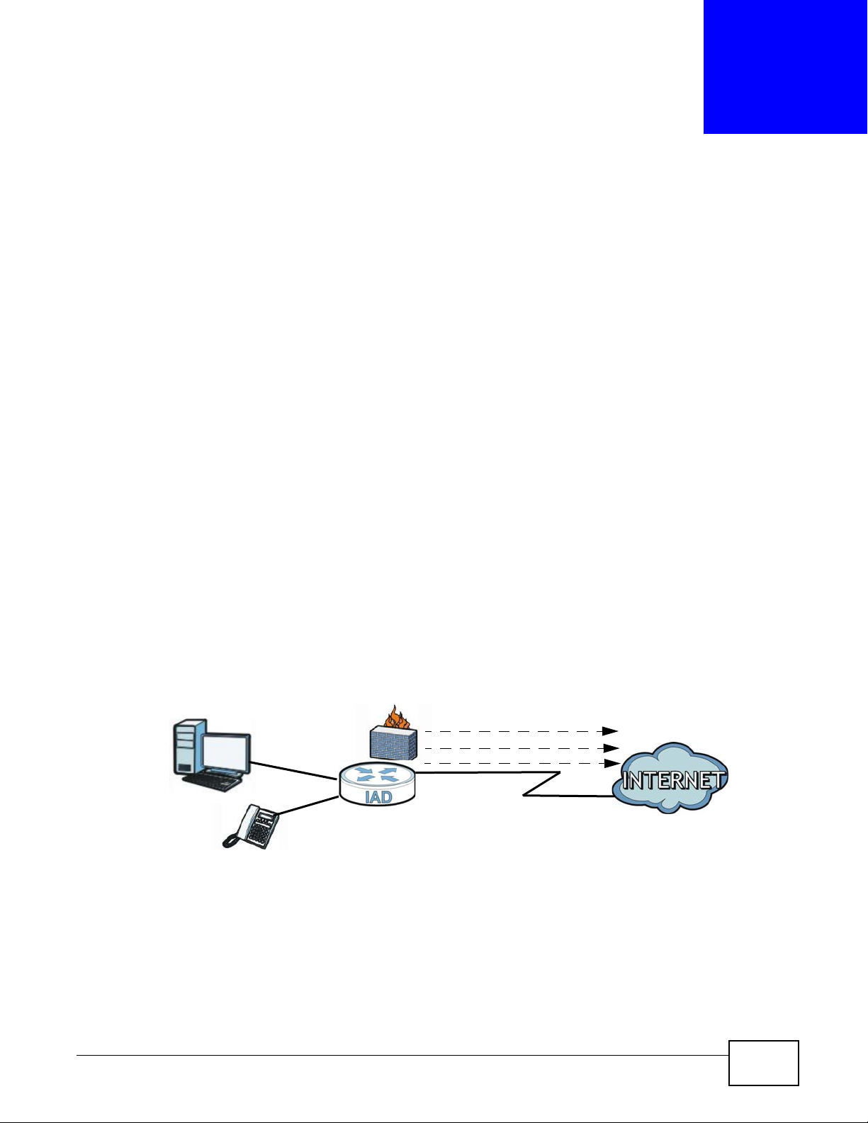
1.2.1 Internet Access
Your Device provides shared Internet access. Computers can connect to the Device’s LAN ports.
Figure 1 Device’s Internet Access Application
1.2.2 VoIP Features
You can register 1 SIP (Session Initiation Protocol) profile (2 accounts for that profile) and use the
Device to make and receive VoIP telephone calls:
FMG3024-D10A / FMG3025-D10A Series User’s Guide 15
Page 16

Chapter 1 Introduction
PSTN
Figure 2 Device’s VoIP Application
The Device sends your call to a VoIP service provider’s SIP server which forwards your calls to
either VoIP or PSTN phones.
16
FMG3024-D10A / FMG3025-D10A Series User’s Guide
Page 17

1.3 Ways to Manage the Device
Use any of the following methods to manage the Device.
• Web Configurator. This is recommended for everyday management of the Device using a
(supported) web browser.
• FTP for firmware upgrades and configuration backup/restore.
1.4 Good Habits for Managing the Device
Do the following things regularly to make the Device more secure and to manage the Device more
effectively.
• Change the password. Use a password that’s not easy to guess and that consists of different
types of characters, such as numbers and letters.
• Write down the password and put it in a safe place.
• Back up the configuration (and make sure you know how to restore it). Restoring an earlier
working configuration may be useful if the device becomes unstable or even crashes. If you
forget your password to access the Web Configurator, you will have to reset the Device to its
factory default settings. If you backed up an earlier configuration file, you would not have to
totally re-configure the Device. You could simply restore your last configuration. Keep in mind
that backing up a configuration file will not back up passwords used to set up PPPoE and VoIP.
Write down any information your ISP provides you.
Chapter 1 Introduction
1.5 The RESET Button
If you forget your password or cannot access the web configurator, you will need to use the RESET
button at the back of the device to reload the factory-default configuration file. This means that y ou
will lose all configurations that you had previously and the passwords will be reset to the defaults.
1 Make sure the POWER LED is on (not blinking).
2 T o set the device back to the factory default settings, press the RESET button for 5 seconds or until
the POWER LED begins to blink and then release it. When the POWER LED begins to blink, the
defaults have been restored and the device restarts.
FMG3024-D10A / FMG3025-D10A Series User’s Guide
17
Page 18

Chapter 1 Introduction
18
FMG3024-D10A / FMG3025-D10A Series User’s Guide
Page 19
2.1 Overview
The web configurator is an HTML-based management interface that allows easy device setup and
management via Internet browser. Use Internet Explorer 6.0 and later versions, Mozilla Firefox 3
and later versions, or Safari 2.0 and later versions. The recommended screen resolution is 1024 by
768 pixels.
In order to use the web configurator you need to allow:
• Web browser pop-up windows from your device. Web pop-up blocking is enabled by default in
Windows XP SP (Service Pack) 2.
• JavaScript (enabled by default).
• Java permissions (enabled by default).
CHAPTER 2
Introducing the Web Configurator
See Appendix C on page 283 if you need to make sure these functions are allowed in Internet
Explorer.
2.1.1 Accessing the Web Configurator
1 Make sure your Device hardware is properly connected (refer to the Quick Start Guide).
2 Launch your web browser.
3 Type "192.168.1.1" as the URL.
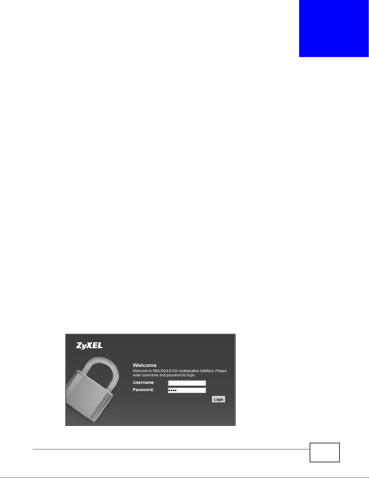
4 A password screen displays. Type “admin” as the default Username and “1234” as the default
password to access the device’s W eb Configur ator. Click Login. If you have changed the password,
enter your password and click Login.
Figure 3 Password Screen
FMG3024-D10A / FMG3025-D10A Series User’s Guide 19
Page 20
Chapter 2 Introdu cing the Web Configurator
Note: For security reasons, the Device automatically logs you out if you do not use the
web configurator for five minutes (default). If this happens, log in again.
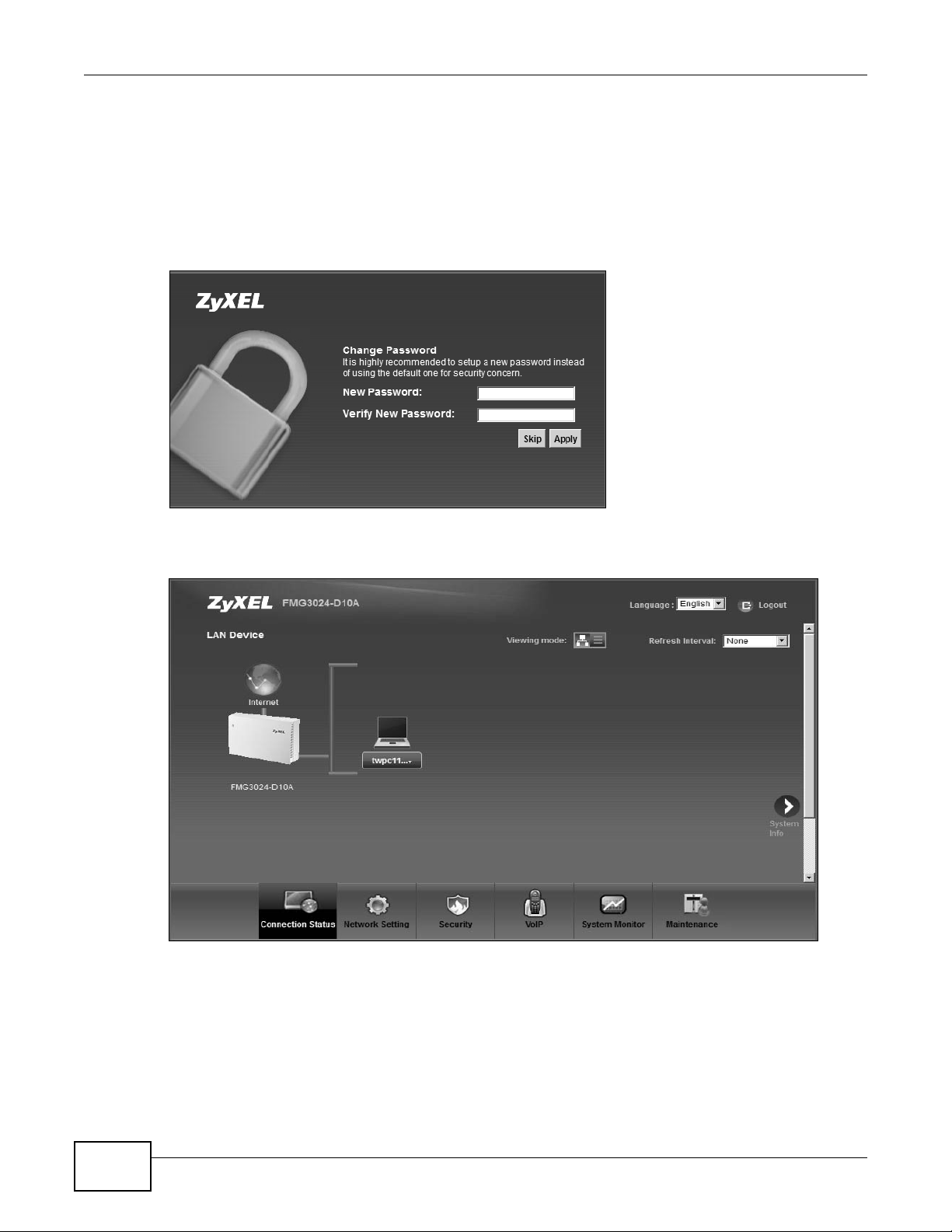
5 The following screen displays if you have not yet changed your password. It is strongly
recommended you change the default password. Enter a new password, retype it to confirm and
click Apply; alternatively click Skip to proceed to the main menu if you do not want to change the
password now.
Figure 4 Change Password Screen
6 The Connection Status screen appears.
Figure 5 Connection Status
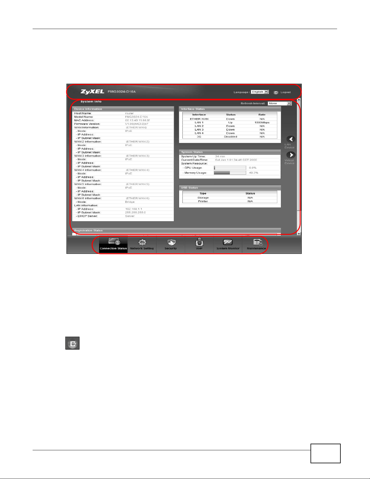
7 Click System Info to display the System Info screen, where you can view the Device’s interface
and system information.
20
FMG3024-D10A / FMG3025-D10A Series User’s Guide
Page 21
2.2 The Web Configurator Layout
B
C
A
a
b
Click Connection Status > System Info to show the following screen.
Figure 6 Web Configurator Layout
Chapter 2 Introducing the Web Configurator
As illustrated above, the main screen is divided into these parts:
• A - title bar
• B - main window
• C - navigation panel
2.2.1 Title Bar
The title bar shows the following icon in the upper right corner.
Click this icon to log out of the web configurator.
2.2.2 Main Window
The main window displays information and configuration fields. It is discussed in the rest of this
document.
After you click System Info on the Connection Status screen, the System Info screen is
displayed. See Chapter 4 on page 62 for more information about the System Info screen.
FMG3024-D10A / FMG3025-D10A Series User’s Guide
21
Page 22
Chapter 2 Introdu cing the Web Configurator
If you click LAN Device on the System Info screen (a in Figure 6 on page 21), the Connection
Status screen appears. See Chapter 4 on page 61 for more information about the Connection
Status screen.
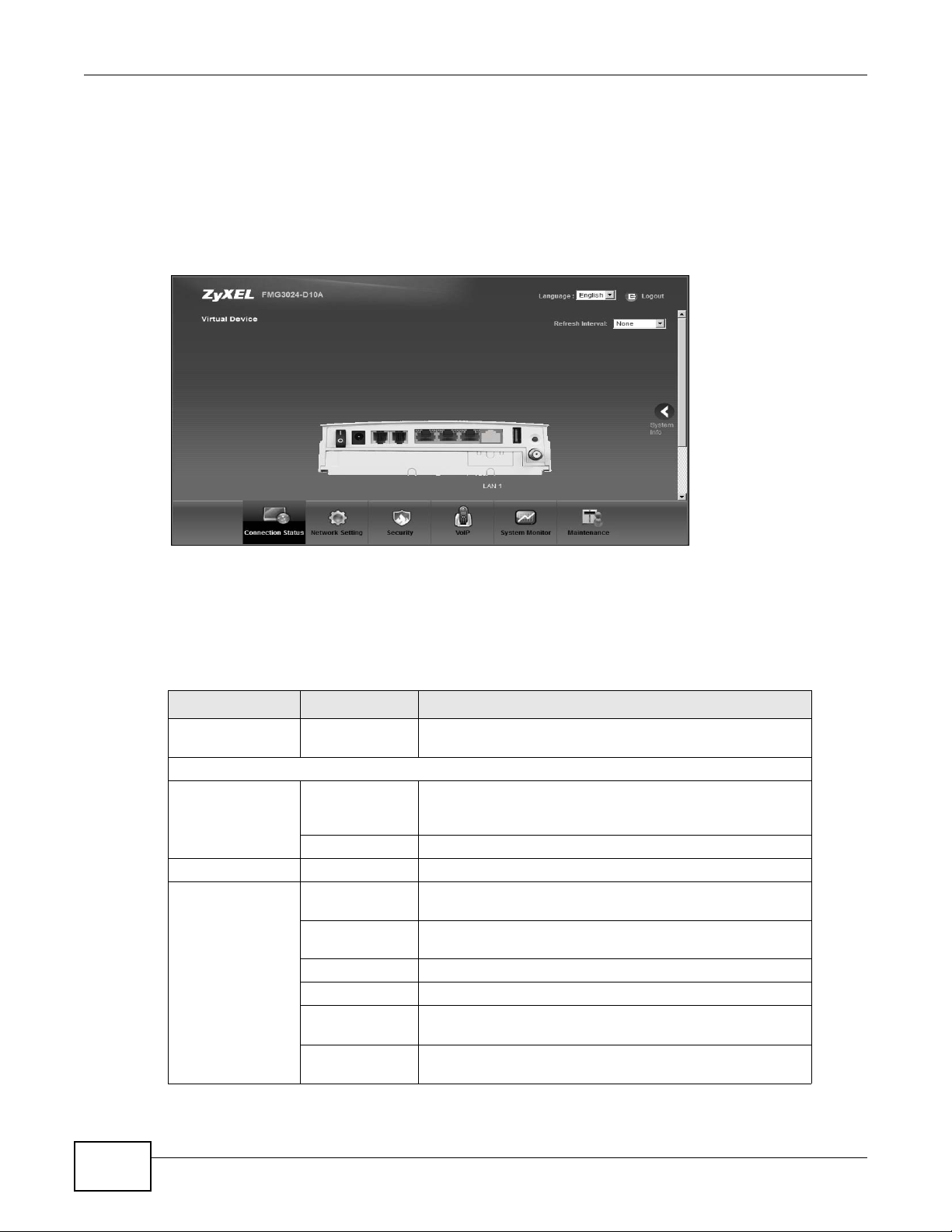
If you click Virtual Device on the System Info screen (b in Figure 6 on page 21), a visual graphic
appears, showing the connection status of the Device’s ports. The connected ports are in color and
disconnected ports are gray.
Figure 7 Virtual Device
2.2.3 Navigation Panel
Use the menu items on the navigation panel to open screens to configure Device features. The
following table describes each menu ite m.
Table 1 Navigation Panel Summary
LINK TAB FUNCTION
Connection Status This screen shows the network status of the Device and
Network Setting
Broadband Broadband Use this screen to view and modify your WAN interface. You
3G Backup Use this screen to configure the 3G WAN connection.
CATV CATV Use this screen to enable cable television functions.
Home
Networking
LAN Setup Use this screen to configure LAN TCP/IP settings, and other
Static DHCP Use this screen to assign specific IP addresses to individual
UPnP Use this screen to enable the UPnP function.
File Sharing Use this screen to enable file sharing via the Device.
Media Server Use this screen to enable or disable the sharing of media
Printer Server Use this screen to enable or disable sharing of a USB printer
computers/devices connected to it.
can also configure ISP parameters, WAN IP address
assignment, DNS servers and other advanced properties.
advanced properties.
MAC addresses.
files.
via your Device.
22
FMG3024-D10A / FMG3025-D10A Series User’s Guide
Page 23

Chapter 2 Introducing the Web Configurator
Table 1 Navigation Panel Summary (continued)
LINK TAB FUNCTION
Static Route Static Route Use this screen to view and set up static routes on the
Device.
DNS Route D NS Route Use this screen to view and configure DNS routes.
QoS General Use this screen to enable QoS and decide allowable
bandwidth using QoS.
Queue Setup
Class Setup Use this screen to set up classifiers to sort traffic into
Monitor
NAT Port Forwarding Use this screen to make your local servers visible to the
Sessions Use this screen to limit the number of NAT sessions a single
Dynamic DNS Dynamic DNS Use this screen to allow a static hostname alias for a
Interface
Group
Security
Firewall General Use this screen to activate/deactivate the firewall.
MAC Filter MAC Filter Use this screen to allow specific devices t o access the
Parental
Control
Certificates Local Certificates Use this screen to generate and export self-signed
VPN VPN Use this screen to configure VPN settings.
VoIP
SIP SIP Service
Phone Phone Device Use this screen to set which phone ports use which SIP
Call Rule Speed Dial Use this screen to configure speed dial for SIP phone
System Monitor
Log Phone Log Use this screen to view the Device’s phone logs.
Interface Group Use this screen to create a new interface group.
Services Use this screen to set the default action to tak e on out g oin g
Parental Control Use this screen to define time periods and days during which
Trusted CA Use this screen to save CA certificates to the Device.
Provider
SIP Account Use this screen to set up information about your SIP account
VoIP Call History Use this screen to view the Device’s VoIP call history.
Use this screen to configure QoS queue assignment.
different flows and assign priority and define actions to be
performed for a classified traffic flow.
Use this screen to view each queue’s statistics.
outside world.
client can establish.
dynamic IP address.
network traffic.
Device.
the Device performs parental control and/or block web sites
with the specific URL.
certificates or certification requests and import the Device’s
CA-signed certificates.
Use this screen to configure your Device’s Voice over IP
settings.
and configure audio settings such as volume levels for the
phones connected to the Device.
accounts.
numbers that you call often.
FMG3024-D10A / FMG3025-D10A Series User’s Guide
23
Page 24

Chapter 2 Introdu cing the Web Configurator
Table 1 Navigation Panel Summary (continued)
LINK TAB FUNCTION
Traffic Status WAN Use this screen to view the status of all network traffic going
LAN Use this screen to view the status of all network traffic going
NAT Use this screen to view the status of NAT se ss ion s on the
3G Backup Use this screen to view the status of 3G Backup on the
VoIP Status VoIP Status Use this screen to view the SIP, phone, and call status of the
Maintenance
Users Account Users Account Use this screen to configure the passwords your user
Remote MGMT Remote MGMT Use this screen to enable specific traffic directions for
SNMP SNMP Use this screen to configure SNMP settings.
System System Use this screen to configure the Device’s name, domain
Time Time Setting Use this screen to change your Device’s time and date.
Log Setting Log Setting Use this screen to select which logs and/or immediate alerts
Firmware
Upgrade
Backup/
Restore
Reboot Reboot Use this screen to reboot the Device without turning the
Diagnostic Ping/TraceRoute Use this screen to test the connections to other devices.
Auto Provision Auto Provision Use this screen to configure Auto Provision settings for
Firmware
Upgrade
Backup/Restore Use this screen to backup and restore your device’s
through the WAN port of the Device.
through the LAN ports of the Device.
Device.
Device.
Device.
accounts.
network services.
name, management inactivity time-out.
your device is to record. You can also set it to e-mail the logs
to you.
Use this screen to upload firmware to your device.
configuration (settings) or reset the factory default settings.
power off.
automatically updating the Device settings.
24
FMG3024-D10A / FMG3025-D10A Series User’s Guide
Page 25

3.1 Overview
This chapter contains the following tutorials:
• Setting Up Your W A N Connection
• Setting Up NAT Port Forwarding
• How to Make a VoIP Call
• Using the File Sharing Feature
• Using the Media Server Feature
• Using the Print Server Feature
• Configuring Static Route for Routing to Another Network
• Configuring QoS Queue and Class Setup
• Access the Device Using DDNS
CHAPTER 3
Tutorials
3.2 Setting Up Your WAN Connection
This tutorial shows you how to set up your Internet connection using the web configurator.
Use the information from your Internet Service Provider (ISP) to configure the Device. Do the
following steps:
1 Connect the Device properly . Refer to the Quick Start Guide for details on the Device’s hardware
connection.
2 Connect one end of a fiber cable to the fiber port for data traffic on your Device.
3 Connect one end of Ethernet cable to an Ethernet port on the Device and the other end to a
computer that you will use to access the web configurator.
4 Connect the Device to a power source, turn it on and wait for the POWER LED to become a steady
green. Turn on the modem provided by your ISP as well as the computer.
Account Configuration
1 Click Network Setting > Broadband to open the Broadband screen. Click Add new WAN
Interface.
FMG3024-D10A / FMG3025-D10A Series User’s Guide 25
Page 26
Chapter 3 Tutorials
D=192.168.1.34
WAN
LAN
port 666
A
2 Enter the settings for your connection as specified by the ISP and save your changes. You should
see a summary of your new connection setup in the Broadband screen.
3 Try to connect to a website, such as “www.zyxel.com” to see if you have correctly set up your
Internet connection. Be sure to contact your service provider for any information you need to
configure the WAN screens.
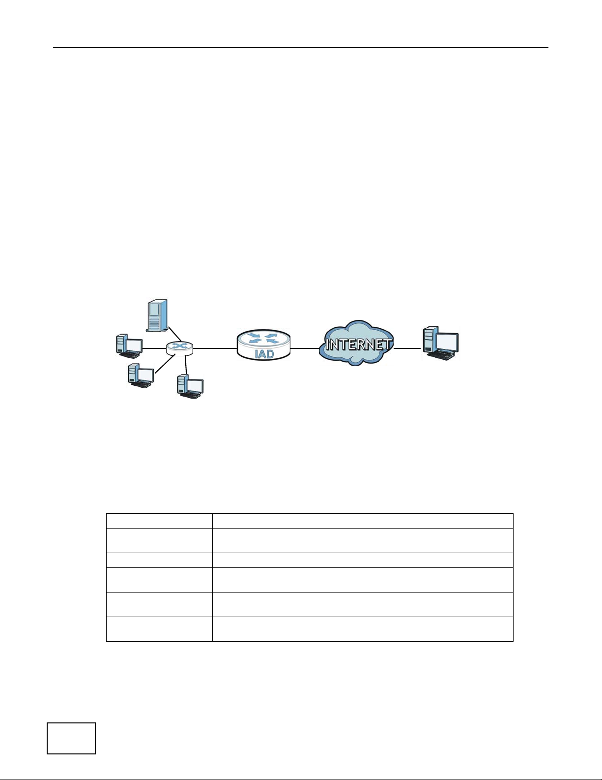
3.3 Setting Up NAT Port Forwarding
In this tutorial, you manage the Doom server on a computer behind the Device. In order for players
on the Internet (like A in the figure below) to communicate with the Doom server, you need to
configure the port settings and IP address on the Device. Traffic should be forwarded to the port
666 of the Doom server computer which has an IP address of 192.168.1.34.
Tutorial: NAT Port Forwarding Setup
You may set up the port settings by configuring the port settings for the Doom server computer
(see Chapter 10 on page 134 for more information).
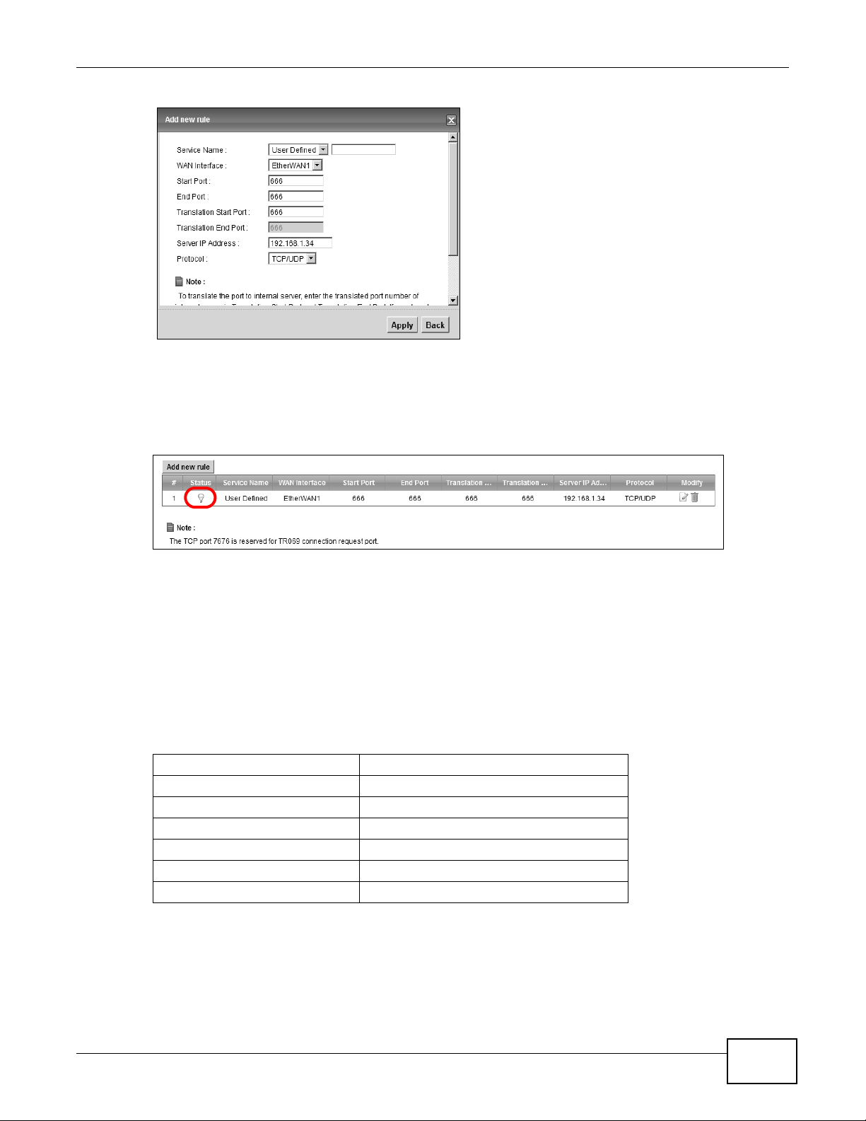
1 Click Network Setting > NAT > Port Forwarding. Click Add new rule.
2 Enter the following values:
Service Name Select User Defined.
WAN Interface Select the WAN interface through which the Doom service is forwarded.
This is the default interface for this example, which is EtherWAN1.
Start/End Ports 666
Translation Start/End
Ports
Server IP Address Enter the IP address of the Doom server. This is 192.168.1.34 for this
Protocol Select TCP/UDP. This should be the protocol supported by the Doom
666
example.
server.
26
FMG3024-D10A / FMG3025-D10A Series User’s Guide
Page 27
Chapter 3 Tutorials
3 Click Apply.
4 The port forwarding settings you configured should appear in the table. Make sure the bulb in
Status is the color yellow, meaning it is activated. Click Apply to have the Device start forw arding
port 666 traffic to the computer with IP address 192.168.1.34.
Players on the Internet then can have access to your Doom server.
3.4 How to Make a VoIP Call
You can register a SIP account with the SIP server and make voice calls over the Internet to
another VoIP device.
The following parameters are used in this example:
SIP Service Provider Name ServiceProvider1
SIP Server Address sip.example.com
REGISTER Server Address registersip.example.com
SIP Service Domain sip.example.com
SIP Account Number 12345678
Username ChangeMe
Password ThisIsMySIP
3.4.1 VoIP Calls With a Registered SIP Account
T o use a registered SIP account, you should configure the SIP service provider and applied for a SIP
account.
FMG3024-D10A / FMG3025-D10A Series User’s Guide
27
Page 28
Chapter 3 Tutorials
3.4.1.1 SIP Service Provider Configuration
Follow the steps below to configure your SIP service provider.
1 Make sure your Device is connected to the Internet.
2 Open the web configurator.
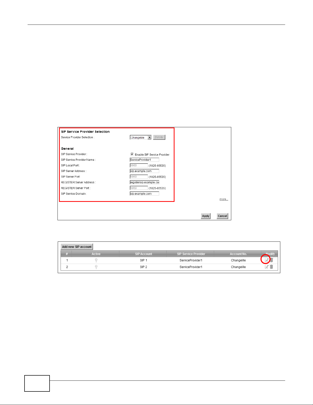
3 Click VoIP > SIP to open the SIP Service Provider screen. Select ChangeMe from the Service
Provider Selection drop-down list box.
4 Select the Enable check box of SIP Service Provider and enter ServiceProvider1 as the SIP
Service Provider Name. Enter the SIP Server Address, REGISTER Server Address, and SIP
Service Domain provided by your ISP accordingly. Click Apply.
5 Go to the SIP Account screen, click the Edit icon of SIP 1.
6 Select the Active SIP Account check box, then enter the SIP Account Number , Username, and
Password. Leave other settings as default.
7 Click Apply to save your settings.
28
FMG3024-D10A / FMG3025-D10A Series User’s Guide
Page 29
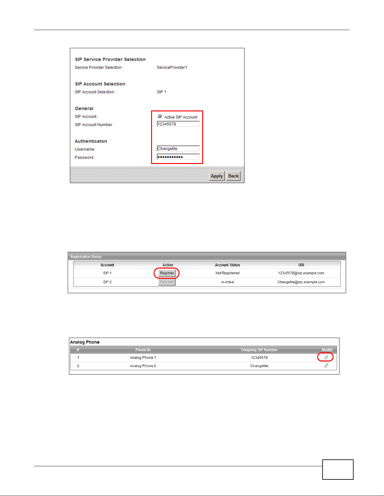
3.4.1.2 SIP Account Registration
Chapter 3 Tutorials
Follow the steps below to register and activate your SIP account.
1 Click Connection Status > System Info to check if your SIP account has been registered
successfully . If the status is Not Regi stered, check your Internet connection and click Register to
register your SIP account.
Tutorial: Registration Status
3.4.1.3 Analog Phone Configuration
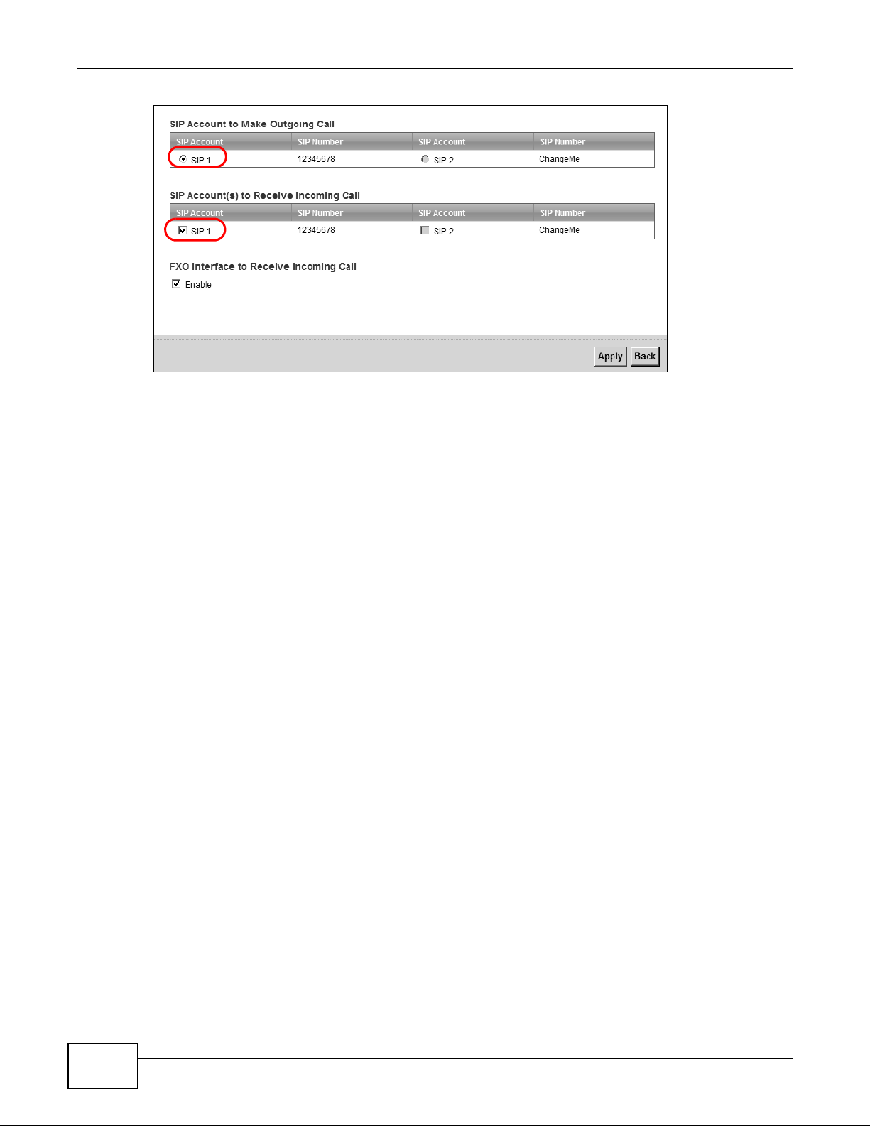
1 Click VoIP > Phone to open the Phone Device screen. Click the Edit icon next to Analog Phone
1 to configure the first phone port.
2 Select SIP 1 from the SIP Account in the SIP Account to Make Outgoing Call section to have
the phone (connected to the first phone port) use the registered SIP 1 account to make outgoing
calls.
3 Select the SIP 1 check box in the SIP Account(s) to Receive Incoming Call section to have the
phone (connected to the first phone port) receive phone calls for the SIP 3 account.
4 Click Apply to save your changes.
FMG3024-D10A / FMG3025-D10A Series User’s Guide
29
Page 30
Chapter 3 Tutorials
Tutorial: VoIP > Phone
3.4.1.4 Making a VoIP Call
1 Make sure you connect a telephone to the first phone port on the Device.
2 Make sure the Device is on and connected to the Internet.
3 Pick up the phone receiver.
4 Dial the VoIP phone number you want to call.
3.5 Using the File Sharing Feature
In this section you can:
• Set up file sharing of your USB device from the Device
• Access the shared files of your USB device from a computer
3.5.1 Set Up File Sharing
To set up file sharing you need to connect your USB device, enable file sharing and set up your
share(s).
3.5.1.1 Activate File Sharing
1 Connect your USB device to one of the USB ports at the back panel of the Device.
2 Click Network Setting > Home Networking > File Sharing. Select Enable and click Apply to
activate the file sharing function. The Device automatically adds your USB device to the Share
Directory List.
30
FMG3024-D10A / FMG3025-D10A Series User’s Guide
Page 31

3.5.1.2 Set up File Sharing on Your Device
You also need to set up file sharing on your Device in order to share files.
1 Click Add new share in the File Sharing screen to configure a new share. Select your USB device
from the Volume drop-down list box.
2 Click Browse to browse through all the files on your USB device. Select the folder that you want to
add as a share. In this example, select Bob’s_Share. Click Apply.
Chapter 3 Tutorials
3 You can add a description for the share or leave it blank. The Add Share Directory screen should
look like the following.Click Apply to finish.
Tutorial: USB Services > Fil e Sharing > Share Configuration
4 This sets up the file sharing server. You can see the USB storage device listed in the table below.
Tutorial: USB Services > Fil e Sharing > Share Configuration (2)
FMG3024-D10A / FMG3025-D10A Series User’s Guide
31
Page 32

Chapter 3 Tutorials
3.5.2 Access Your Shared Files From a Computer
You can use Windows Explorer to access the file storage devices connected to the Device.
Note: The examples in this User’s Guide show you how to use Microsoft’s Windows XP to
browse your shared files. Refer to your operating system’s documentation for how
to browse your file structure.
Open Windows Explorer to access Bob’s Share using Windows Explorer browser.
In Windows Explorer’s Address bar type a double backslash “\\” followed by the IP address of the
Device (the default IP address of the Device is 192.168.1.1) and press [ENTER]. The share folder
Bob’s_Share is available.
File Sharing via Windows Explore r
Once you access Bob’s_Share via your Device, you do n ot have to relogin unless you restart your
computer.
3.6 Using the Media Server Feature
Use the media server feature to play files on a computer or on your television (using DMA-2500).
This section shows you how the media server feature works using the following media clients:
• Microsoft (MS) Windows Media Player
Media Server works with Windows Vista and Windows 7. Make sure your computer is able to play
media files (music, videos and pictures).
• ZyXEL DMA-2500, a digital media adapter
You need to set up the DMA-2500 to work with your television (TV). R efer to the DMA-2500 Quick
Start Guide for the correct hardware connections.
Before you begin, connect the USB storage device containing the media files you want to play to the
USB port of your Device.
3.6.1 Configuring the Device
32
Note: The Media Server feature is enabled by default.
To use your Device as a media server, click Network Setting > Home Networking > Media
Server.
FMG3024-D10A / FMG3025-D10A Series User’s Guide
Page 33

Tutorial: USB Services > Me dia Server
Computer with
ZyXEL Device
USB Storage Device
Windows Media Player
Check Enable Media Server and click Apply . This enables DLNA-compliant media clients to play
the video, music and image files in your USB storage device.
3.6.2 Using Windows Media Player
This section shows you how to play the media files on the USB storage device connected to your
Device using Windows Media Player.
Tutorial: Media Server Setup (Using Windows Media Player)
Chapter 3 Tutorials
Windows Vista
1 Open Windows Media Player and click Library > Media Sharing as follows.
Tutorial: Media Sharing using Windows Vista
FMG3024-D10A / FMG3025-D10A Series User’s Guide
33
Page 34

Chapter 3 Tutorials
2 Check Find media that others are sharing in the following screen and click OK.
Tutorial: Media Sharing using Windows Vista (2)
3 In the Library screen, check the left panel. The Windows Media Player should detect the Device.
Tutorial: Media Sharing using Windows Vista (3)
The Device displays as a playlist. Clicking on the category icons in the right panel shows you the
media files in the USB storage device attached to your Device.
Windows 7
1 Open Windows Media Player. It should automatically detect the Device.
34
FMG3024-D10A / FMG3025-D10A Series User’s Guide
Page 35

Chapter 3 Tutorials
Tutorial: Media Sharing using Windows 7 (1)
If you cannot see the Device in the left panel as shown above, right-click Other Libraries >
Refresh Other Libraries.
2 Select a category in the left panel and wait for Windows Media Player to connect to the Device.
Tutorial: Media Sharing using Windows 7 (2)
3 In the right panel, you should see a list of files available in the USB storage device.
FMG3024-D10A / FMG3025-D10A Series User’s Guide
35
Page 36

Chapter 3 Tutorials
DMA-2500
ZyXEL Device
USB Storage Device
Tutorial: Media Sharing using Windows 7 (2)
3.6.3 Using a Digital Media Adapter
This section shows you how you can use the Device with a ZyXEL DMA-2500 to play media files
stored in the USB storage device in your TV screen.
Note: For this tutorial, your DMA-2500 should already be set up with the TV according to
the instructions in the DMA-2500 Quick Start Guide.
1 Connect the DMA-2500 to an available LAN port in your Device.
Tutorial: Media Server Setup (Using DMA)
2 Turn on the TV and wait for the DMA-2500 Home screen to appear. Using the remote control, go to
MyMedia to open the following screen. Select the Device as your media server.
36
FMG3024-D10A / FMG3025-D10A Series User’s Guide
Page 37

Chapter 3 Tutorials
Tutorial: Media Sharing using DMA-2500
3 The screen shows you the list of available media files in the USB storage device. Select the file you
want to open and push the Play button in the remote control.
Tutorial: Media Sharing using DMA-2500 (2)
3.7 Using the Print Server Feature
In this section you can:
• Configure a TCP/IP Printer Port
• Add a New Printer Using Windows
• Add a New Printer Using Macintosh OS X
Configure a TCP/IP Printer Port
This example shows how you can configure a TCP/IP printer port. This example is done using the
Windows 2000 Professional operating system. Some menu items may look different on your
operating system. The TCP/IP port must be configured with the IP address of the Device and must
FMG3024-D10A / FMG3025-D10A Series User’s Guide
37
Page 38

Chapter 3 Tutorials
use the RAW protocol to communicate with the printer. Consult your operating systems
documentation for instructions on how to do this or follow the instructions below if you have a
Windows 2000/XP operating system.
1 Click Start > Settings, then right click on Printers and select Open.
Tutorial: Open Printers Wind ow
The Printers folder opens up. First you need to open up the properties windows for the printer you
want to configure a TCP/IP port.
2 Locate your printer.
3 Right click on your printer and select Properties.
Tutorial: Open Printer Prop erties
4 Select the Ports tab and click Add Port...
38
FMG3024-D10A / FMG3025-D10A Series User’s Guide
Page 39

Chapter 3 Tutorials
Tutorial: Printer Properties Wind ow
5 A Printer Ports window appears. Select Standard TCP/IP Port and click New Port...
Tutorial: Add a Port Window
6 Add Standard TCP/IP Printer Port Wizard window opens up. Click Next to start configuring the
printer port.
Tutorial: Add a Port Wizard
7 Enter the IP address of the Device to which the printer is connected in the Printer Name or IP
Address: field. In our example we use the default IP address of the Device, 192.168.1.1. The Port
Name field updates automatically to reflect the IP address of the port. Click Next.
FMG3024-D10A / FMG3025-D10A Series User’s Guide
39
Page 40

Chapter 3 Tutorials
Note: The computer from which you are configuring the TCP/IP printer port must be on
Tutorial: Enter IP Address of the Device
8 Select Custom under Device Type and click Settings.
Tutorial: Custom Port Set tings
the same LAN in order to use the printer sharing function.
9 Confirm the IP address of the Device in the IP Address field.
10 Select Raw under Protocol.
11 The Port Number is automatically configured as 9100. Click OK.
40
FMG3024-D10A / FMG3025-D10A Series User’s Guide
Page 41

Tutorial: Custom Port Set tings
12 Continue through the wizard, apply your settings and close the wizard window.
Tutorial: Finish Adding the TCP/IP Port
Chapter 3 Tutorials
13 Repeat steps 1 to 12 to add this printer to other computers on your network.
Add a New Printer Using Windows
This example shows how to connect a printer to your Device using the Windows XP Professional
operating system. Some menu items may look different on your operating system.
FMG3024-D10A / FMG3025-D10A Series User’s Guide
41
Page 42

Chapter 3 Tutorials
1 Click Start > Control Panel > Printers and Faxes to open the Printers and Faxes screen. Click
Add a Printer.
Tutorial: Printers Folder
2 The Add Printer Wizard screen displays. Click Next.
Tutorial: Add Printer Wizard: Welcome
3 Select Local printer attached to this computer and click Next.
42
FMG3024-D10A / FMG3025-D10A Series User’s Guide
Page 43

Tutorial: Add Printer Wizard: Local or N etwork Printer
4 Select Create a new port and Standard TCP/IP Port. Click Next.
Tutorial: Add Printer Wizard: Select the Prin ter Port
Chapter 3 Tutorials
5 Add Standard TCP/IP Printer Port Wizard window opens up. Click Next to start configuring the
printer port.
Tutorial: Add a Port Wizard
FMG3024-D10A / FMG3025-D10A Series User’s Guide
43
Page 44

Chapter 3 Tutorials
6 Enter the IP address of the Device to which the printer is connected in the Printer Name or IP
Address: field. In our example we use the default IP address of the Device, 192.168.1.1. The Port
Name field updates automatically to reflect the IP address of the port. Click Next.
Note: The computer from which you are configuring the TCP/IP printer port must be on
Tutorial: Enter IP Address of the Device
the same LAN in order to use the printer sharing function.
7 Select Custom under Device Type and click Settings.
Tutorial: Custom Port Set tings
8 Confirm the IP address of the Device in the Printer Name or IP Address field.
9 Select Raw under Protocol.
10 The Port Number is automatically configured as 9100. Click OK to go back to the previous screen
and click Next.
44
FMG3024-D10A / FMG3025-D10A Series User’s Guide
Page 45

Tutorial: Custom Port Set tings
11 Click Finish to close the wizard window.
Tutorial: Finish Adding the TCP/IP Port
Chapter 3 Tutorials
12 Select the make of the printer that you want to connect to the prin t server in the Manufacturer list
of printers.
13 Select the printer model from the list of Printers.
14 If your printer is not displayed in the list of Printers, you can insert the printer driver installation
CD/disk or download the driver file to your computer, click Have Disk… and install the new printer
driver.
15 Click Next to continue.
FMG3024-D10A / FMG3025-D10A Series User’s Guide
45
Page 46

Chapter 3 Tutorials
Tutorial: Add Printer Wizard: Printer Driv er
16 If the following screen displays, select Keep existing driver radio button and click Next if you
already have a printer driver installed on your computer and you do not want to change it.
Otherwise, select Replace existing driver to replace it with the new driver you selected in the
previous screen and click Next.
Tutorial: Add Printer Wizard: Use Existin g Driver
17 Type a name to identify the printer and then click Next to continue.
46
FMG3024-D10A / FMG3025-D10A Series User’s Guide
Page 47

Chapter 3 Tutorials
Tutorial: Add Printer Wizard: Name Your Printer
18 The Device is a print server itself and you do not need to have your computer act as a print server
by sharing the printer with other users in the same network; just select Do not share this printer
and click Next to proceed to the following screen.
Tutorial: Add Printer Wizard: Printer Sharin g
19 Select Yes and then click the Next button if you want to print a test page. A pop-up screen displays
to ask if the test page printed correctly. Otherwise select No and then click Next to continue.
FMG3024-D10A / FMG3025-D10A Series User’s Guide
47
Page 48

Chapter 3 Tutorials
Tutorial: Add Printer Wizard: Print Test Page
20 The following screen shows your current printer settings. Select Finish to complete adding a new
printer.
Tutorial: Add Printer Wizard Complete
Add a New Printer Using Macintosh OS X
Complete the following steps to set up a print server driver on your Macintosh computer.
1 Click the Print Center icon located in the Macintosh Dock (a place holding a series of icons/
shortcuts at the bottom of the desktop). Proceed to step 6 to continue. If the Print Center icon is
not in the Macintosh Dock, proceed to the next step.
2 On your desktop, double-click the Macintosh HD icon to open the Macintosh HD window.
Tutorial: Macintosh HD
3 Double-click the Applications folder.
48
FMG3024-D10A / FMG3025-D10A Series User’s Guide
Page 49

Tutorial: Macintosh HD fo lder
4 Double-click the Utilities folder.
Tutorial: Applications Fold er
Chapter 3 Tutorials
5 Double-click the Print Center icon.
Tutorial: Utilities Folder
6 Click the Add icon at the top of the screen.
Tutorial: Printer List Folder
7 Set up your printer in the Printer List configuration screen. Select IP Printing from the drop-
down list box.
8 In the Printer’s Address field, type the IP address of your Device.
9 Deselect the Use default queue on server check box.
10 Type LP1 in the Queue Name field.
FMG3024-D10A / FMG3025-D10A Series User’s Guide
49
Page 50

Chapter 3 Tutorials
11 Select your Printer Model from the drop-down list box. If the printer's model is not listed, select
Generic.
Tutorial: Printe r Configuration
12 Click Add to select a printer model, save and close the Printer List configuration screen.
Tutorial: Printer Model
13 The Name LP1 on 192.168.1.1 displays in the Printer List field. The default printer Name
displays in bold type.
Tutorial: Print Server
Your Macintosh print server driver setup is complete. You can now use the Device’s print server to
print from a Macintosh computer.
50
FMG3024-D10A / FMG3025-D10A Series User’s Guide
Page 51

Chapter 3 Tutorials
N2
B
N1
A
R
3.8 Configuring Static Route for Routing to Another Network
In order to extend your Intranet and control traffic flowing directions, you may connect a router to
the Device’s LAN. The router may be used to separate two department networks. This tutorial
shows how to configure a static routing rule for two network routings.
In the following figure, router R is connected to the Device’s LAN. R connects to two networks, N1
(192.168.1.x/24) and N2 (192.168.10.x/24). If you want to send traffic from computer A (in N1
network) to computer B (in N2 network), the traffic is sent to the Device’ s W AN default gatewa y by
default. In this case, B will never receive the traffic.
FMG3024-D10A / FMG3025-D10A Series User’s Guide
51
Page 52

Chapter 3 Tutorials
N2
B
N1
A
R
You need to specify a static routing rule on the Device to specify R as the router in charge of
forwarding traffic to N2. In this case, the Device routes traffic from A to R and then R routes the
traffic to B.This tutorial uses the following example IP settings:
Table 2 IP Settings in this Tutorial
DEVICE / COMPUTER IP ADDRESS
The Device’s WAN 172.16.1.1
The Device’s LAN 192.168.1.1
A 192.168.1.34
R’s N1 192.168.1.253
R’s N2 192.168.10.2
B 192.168.10.33
To configure a static route to route traffic from N1 to N2:
1 Click Network Setting > Routing. Click Add New Static Route.
2 Configure the Static Route Setup screen using the following settings:
•Select Active.
• Specify a descriptive name for this routing rule.
•Type 192.168.10.0 and subnet mask 255.255.255.0 for the destination, N2.
•Type 192.168.1.253 (R’s N1 address) in the Gateway IP Address field.
52
FMG3024-D10A / FMG3025-D10A Series User’s Guide
Page 53

Chapter 3 Tutorials
Click Apply. The Routing screen should display the route you just added.
Now B should be able to receive traffic from A. You may need to additionally configure B’s firewall
settings to allow specific traffic to pass through.
3.9 Configuring QoS Queue and Class Setup
This section contains tutorials on how you can configure the QoS screen.
Note: Voice traffic will not be affected by the user-defined QoS settings on the Device. It
always gets the highest priority.
Let’s say you are a team leader of a small sales branch office. You want to prioritize e-mail traffic
because your task includes sending urgent updates to clients at least twice every hour. You also
upload data files (such as logs and e-mail archives) to the FTP server throughout the day. Your
colleagues use the Internet for research, as well as chat applications for communicating with other
branch offices.
In the following figure, your Internet connection has an upstream transmission bandwidth of
10,000 kbps. For this example, you want to configure QoS so that e-mail traffic gets the highest
priority with at least 5,000 kbps. You can do the following:
• Configure a queue to assign the highest priority queue (7) to e-mail traffic from the LAN
interface, so that e-mail traffic would not get delayed when there is network congestion.
• Note the IP address (192.168.1.23 for example) and/or MAC address (AA:FF:AA:FF:AA:FF for
example) of your computer and map it to queue 7.
Note: QoS is applied to traffic flowing out of the Device.
Traffic that does not match this class is assigned a priority queue based on the internal QoS
mapping table on the Device.
FMG3024-D10A / FMG3025-D10A Series User’s Guide
53
Page 54

Chapter 3 Tutorials
10,000 kbps
DSL
E-mail: Queue 7
Your computer
IP=192.168.1.23
A colleague’s computer
Other traffic: Automatic classifier
and/or
MAC=AA:FF:AA:FF:AA:FF
ZyXEL Device
QoS Example
1 Click Network Setting > QoS > General and check Active. Set your WAN Managed Upstream
Bandwidth to 10,000 kbps (or leave this blank to have the Device automatically determine this
figure). Click Apply to save your settings.
Tutorial: Advanced > QoS
2 Go to Network Setting > QoS > Queue Setup. Click Add new Queue to create a new queue. In
the screen that opens, check Active and enter or select the following values, then click Apply.
• Name: Email
• Priority: 7 (High)
• Weight: 15
• Rate Limit: 5,000 (kbps)
Tutorial: Advanced > QoS > Queue Setup
3 Go to Network Setting > QoS > Class Setup. Click Add new Classifier to create a new class.
Check Active and follow the settings as shown in the screen below. Then click Apply.
54
FMG3024-D10A / FMG3025-D10A Series User’s Guide
Page 55

Tutorial: Advanced > QoS > Class Setup
Chapter 3 Tutorials
Class Name Give a class name to this traffic, such as Email in this
example.
To Queue Link this to a queue created in the QoS > Queue Setup
From Interface This is the interface from which the traffic will be coming
Ether Type Select IP to identify the traffic source by its IP address or
MAC Address Type the MAC address of your computer -
IP Address Type the IP address of your computer - 192.168.1.23.
IP Protocol Select User defined and enter 25 as the IP Protocol.
screen, which is the Email queue created in this example.
from. Select Lan.
MAC address.
AA:FF:AA:FF:AA:FF. Type the MAC Mask if you know it.
Type the IP Subnet Mask if you know it.
This maps e-mail traffic to queue 7 created in the previous screen (see the IP Protocol field). This
also maps your computer’s IP address and MAC address to queue 7 (see the Source fields).
4 Verify that the queue setup works by checking Network Setting > QoS > Monitor. This shows
the bandwidth allotted to e-mail traffic compared to other network traffic.
FMG3024-D10A / FMG3025-D10A Series User’s Guide
55
Page 56

Chapter 3 Tutorials
w.x.y.z
a.b.c.d
http://zyxelrouter.dyndns.org
A
Tutorial: Advanced > QoS > Monitor
3.10 Access the Device Using DDNS
If you connect your Device to the Internet and it uses a dynamic WAN IP address, it is inconvenient
for you to manage the device from the Internet. The Device’s W AN IP address changes dynamically.
Dynamic DNS (DDNS) allows you to access the Device using a domain name.
To use this feature, you have to apply for DDNS service at www.dyndns.org.
This tutorial shows you how to:
• Registering a DDNS Account on www.dyndns.org
• Configuring DDNS on Your Device
• Testing the DDNS Setting
Note: If you have a private WAN IP address, then you cannot use DDNS.
3.10.1 Registering a DDNS Account on www.dyndns.org
1 Open a browser and type http://www.dyndns.org.
56
FMG3024-D10A / FMG3025-D10A Series User’s Guide
Page 57

2 Apply for a user account. This tutorial uses UserName1 and 12345 as the username and
password.
3 Log into www.dyndns.org using your account.
4 Add a new DDNS host name. This tutorial uses the following settings as an example.
•Hostname: zyxelrouter.dyndns.org
•Service Type: Host with IP address
• IP Address: Enter the WAN IP address that your Device is currently using. You can find the IP
address on the Device’s web configurator Status page.
Then you will need to configure the same account and host name on the Device later.
3.10.2 Configuring DDNS on Your Device
Configure the following settings in the Network Setting > Dynamic DNS screen.
•Select Active Dynamic DNS.
•Select Dynamic DNS for the DDNS type.
•Type zyxelrouter.dyndns.org in the Host Name field.
• Enter the user name (UserName1) and password (12345).
Chapter 3 Tutorials
Click Apply.
3.10.3 Testing the DDNS Setting
Now you should be able to access the Device from the Internet. To test this:
1 Open a web browser on the computer (using the IP address a.b.c.d) that is connected to the
Internet.
2 Type http://zyxelrouter.dyndns.org and press [Enter].
3 The Device’s login page should appear. You can then log into the Device and manage it.
FMG3024-D10A / FMG3025-D10A Series User’s Guide
57
Page 58

Chapter 3 Tutorials
58
FMG3024-D10A / FMG3025-D10A Series User’s Guide
Page 59

PART II
Technical Reference
The appendices provide general information. Some details may not apply to your Device.
59
Page 60

60
Page 61

CHAPTER 4
Connection Status and System Info
4.1 Overview
After you log into the web configurator, the Connection Status screen appears. This shows the
network connection status of the Device and clients connected to it.
Use the System Info screen to look at the current status of the device, system resources,
interfaces (LAN, WAN), and SIP accounts. You can also register and unregister SIP accounts.
If you click Virtual Device on the System Info screen, a visual graphic appears, showing the
connection status of the Device’s ports. See Section 2.2.2 on page 21 for more information.
4.2 The Connection Status Screen
Use this screen to view the network connection status of the device and its clients. A warning
message appears if there is a connection problem.
If you prefer to view the status in a list, click List View in the Viewing mode selection box. You
can configure how often you want the Device to update this screen in Refresh Interval.
Figure 8 Connection Status: Icon View
FMG3024-D10A / FMG3025-D10A Series User’s Guide 61
Page 62

Chapter 4 Connection Status and System Info
Figure 9 Connection Status: List View
In Icon View, if you want to view information about a client, click the client’ s name and Info . Click
the IP address if you want to change it. If you want to change the name or icon of the client, click
Change name/icon.
In List View, you can also view the client’s information.
4.3 The System Info Screen
Click Connection Status > System Info to open this screen.
Figure 10 System Info Screen
62
FMG3024-D10A / FMG3025-D10A Series User’s Guide
Page 63

Chapter 4 Co nnection Status and System Info
Each field is described in the following table.
Table 3 System Info Screen
LABEL DESCRIPTION
Language Select the web configurator language from the drop-down list box.
Refresh Interval Select how often you want the Device to update this screen from the
Device Information
Host Name This field displays the Device system name. It is used for identification.
Model Name This is the model name of your device.
MAC Address This is the MAC (Media Access Control) or Ethernet address unique to your
Firmware Version This field displays the current version of the firmware inside the device. It
WAN Information
Mode This is the method of encapsulation used by your ISP.
IP Address This field displays the current IP address of the Device in the WAN.
IP Subnet Mask This field displays the current subnet mask in the WAN.
LAN Information
IP Address This field displays the current IP address of the Device in the LAN.
IP Subnet Mask This field displays the current subnet mask in the LAN.
DHCP Server This field displays what DHCP services the Device is providing to the LAN.
DHCPv6 Server This field displays what DHCPv6 services the Device is providing to the
Interface Status
Interface This column displays each interface the Device has.
Status This field indicates whether or not the Device is using the interface.
drop-down list box.
You can change this in the Maintenance > System screen’s Host Name
field.
Device.
also shows the date the firmware version was created. Go to the
Maintenance > Firmware Upgrade screen to change it.
Choices are:
Server - The Device is a DHCP server in the LAN. It assigns IP addresses
to other computers in the LAN.
None - The Device is not providing any DHCP services to the LAN.
LAN. Choices are:
Server - The Device is a DHCPv6 server in the LAN. It assigns IP
addresses to other computers in the LAN.
Relay - The Device acts as a surrogate DHCPv6 server and relays DHCP
requests and responses between the remote server and the clients.
None - The Device is not providing any DHCPv6 services to the LAN.
For the WAN interface, this field displays Up when the Device i s us ing th e
interface and Down when the Device is not using the interface.
For the LAN interface, this field displays Up when the Device is using the
interface and Down when the Device is not using the interface.
For the 3G interface, it displays Enabled when 3G is enabled or Disabled
when 3G is disabled.
FMG3024-D10A / FMG3025-D10A Series User’s Guide
63
Page 64

Chapter 4 Connection Status and System Info
Table 3 System Info Screen (continued)
LABEL DESCRIPTION
Rate For the LAN interface, this displays the port speed and duplex setting.
For the WAN interface, this displays the port speed and duplex setting.
For the 3G interface, it displays the m aximu m t ransmission rate when 3G
is enabled or N/A when 3G is disabled.
System Status
System Up Time This field displays how long the Device has been running since it last
Current Date/Time This field displays the current date and time in the Device. Y ou can change
System Resource
CPU Usage This field displays what percentage of the Device’s processing ability is
Memory Usage This field displays what percentage of the Device’s memory is currently
USB Status
Type This shows the type of device connected to the Device.
Status This shows whether the device is currently active (Up). This shows N/A if
Registratio n Status
Account This column displays each SIP account in the Device.
Action This field displays the current registration status of the SIP account. You
started up. The Device starts up when you plug it in, when you restart it
(Maintenance > Reboot), or when you reset it (see Section 1.5 on page
17).
this in Maintenance > Time Setting.
currently used. When this percentage is close to 100%, the Device is
running at full load, and the throughput is not going to improve anymore.
If you want some applications to have more throughput, you should turn
off other applications.
used. Usually, this percentage should not increase much. If memory
usage does get close to 100%, the Devi ce is probably becoming uns table,
and you should restart the device. See Chapter 28 on page 231, or turn
off the device (unplug the power) for a few seconds.
there are no device connected to the Device or the connected device is
not working.
have to register SIP accounts with a SIP server to use VoIP.
If the SIP account is already registered with the SIP server,
64
•Click Unregister to delete the SIP account’s registration in the SIP
server. This does not cancel your SIP account, but it deletes the
mapping between your SIP identity and your IP address or domain
name.
• The second field displays Registered.
If the SIP account is not registered with the SIP server,
•Click Register to hav e the Device attempt to register the SIP account
with the SIP server.
• The second field displays the reason the account is not registered.
Inactive - The SIP account is not active. You can activate it in VoIP >
SIP > SIP Settings.
Register Fail - The last time the Device tried to register the SIP account
with the SIP server, the attempt failed. The Device automatically tries to
register the SIP account when you turn on the Device or when you
activate it.
FMG3024-D10A / FMG3025-D10A Series User’s Guide
Page 65

Chapter 4 Co nnection Status and System Info
Table 3 System Info Screen (continued)
LABEL DESCRIPTION
Account Status This shows Active when the SIP account has been registered and ready
for use or In-Active when the SIP account is not yet registered.
URI This field displays the account number and service domain of the SIP
account. You can change these in VoIP > SIP > SIP Settings.
FMG3024-D10A / FMG3025-D10A Series User’s Guide
65
Page 66

Chapter 4 Connection Status and System Info
66
FMG3024-D10A / FMG3025-D10A Series User’s Guide
Page 67

5.1 Overview
WAN
LAN
This chapter discusses the Device’s Broadband screens. Use these screens to configure your
Device for Internet access.
A WAN (Wide Area Network) connection is an outside connection to another network or the
Internet. It connects your private networks, such as a LAN (Local Area Network) and other
networks, so that a computer in one location can communicate with computers in other locations.
Figure 11 LAN and WAN
CHAPTER 5
Broadband
3G (third generation) standards for the sending and receiving of voice, video, and data in a mobile
environment.
You can attach a 3G wireless adapter to the USB port and set the Device to use this 3G connection
as your WAN or a backup when the wired WAN connection fails.
Figure 12 3G WAN Connection
FMG3024-D10A / FMG3025-D10A Series User’s Guide 67
Page 68

Chapter 5 Broadband
5.1.1 What You Can Do in this Chapter
•Use the Broadband screen to view, remove or add a WAN interface. You can also configure the
WAN settings on the ZyXEL Device for Internet access (Section 5.2 on page 70).
•Use the 3G Backup screen to configure 3G WAN connection (Section 5.3 on page 81).
Table 4 WAN Setup Overview
LAYER-2 INTERFACE INTERNET CONNECTION
INTERFACE MODE
EtherWAN Routing PPPoE PPP user name and password,
Bridge N/A N/A
5.1.2 What You Need to Know
The following terms and concepts may help as you read this chapter.
Encapsulation Method
Encapsulation is used to include data from an upper layer protocol into a lower layer protocol. To set
up a WAN connection to the Internet, you need to use the same encapsulation method used by your
ISP (Internet Service Provider). If your ISP offers a dial-up Internet connection using PPPoE (PPP
over Ethernet), they should also provide a username and password (and service name) for user
authentication.
WAN IP Address
WAN SERVICE
TYPE
IPoE WAN IP address, NAT, DNS
CONNECTION SETTINGS
WAN IP address, DNS server
and default gateway
server and default gateway
68
The WAN IP address is an IP address for the Device, which makes it accessible from an outside
network. It is used by the Device to communicate with other devices in other networks. It can be
static (fixed) or dynamically assigned by the ISP each time the Device tries to access the Internet.
If your ISP assigns you a static WAN IP address, they should also assign you the subnet mask and
DNS server IP address(es).
3G
3G (Third Generation) is a digital, packet-switched wireless technology. Bandwidth usage is
optimized as multiple users share the same channel and bandwidth is only allocated to users when
they send data. It allows fast transfer of voice and non-voice data and provides broadband Internet
access to mobile devices.
IPv6 Introduction
IPv6 (Internet Protocol version 6), is designed to enhance IP address size and features. The
increase in IPv6 address size to 128 bits (from the 32-bit IPv4 address) allows up to 3.4 x 10
addresses. The Device can use IPv4/IPv6 dual stack to connect to IPv4 and IPv6 networks, and
supports IPv6 rapid deployment (6RD).
FMG3024-D10A / FMG3025-D10A Series User’s Guide
38
IP
Page 69

Chapter 5 Broadband
IPv6 Addressing
The 128-bit IPv6 address is written as eight 16-bit hexadecimal blocks separated by colons (:). This
is an example IPv6 address 2001:0db8:1a2b:0015:0000:0000:1a2f:0000.
IPv6 addresses can be abbreviated in two ways:
• Leading zeros in a block can be omitted. So 2001:0db8:1a2b:0015:0000:0000:1a2f:0000 can
be written as 2001:db8:1a2b:15:0:0:1a2f:0.
• Any number of consecutive blocks of zeros can be replaced by a double colon. A double colon can
only appear once in an IPv6 address. So 2001:0db8:0000:0000:1a2f:0000:0000:0015 can be
written as 2001:0db8::1a2f:0000:0000:0015, 2001:0db8:0000:0000:1a2f::0015,
2001:db8::1a2f:0:0:15 or 2001:db8:0:0:1a2f::15.
IPv6 Prefix and Prefix Length
Similar to an IPv4 subnet mask, IPv6 uses an address prefix to represent the network address. An
IPv6 prefix length specifies how many most significant bits (start from the left) in the address
compose the network address. The prefix length is written as “/x” where x is a number. For
example,
2001:db8:1a2b:15::1a2f:0/32
means that the first 32 bits (2001:db8) is the subnet prefix.
IPv6 Subnet Masking
Both an IPv6 address and IPv6 subnet mask compose of 128-bit binary digits, which are divided
into eight 16-bit blocks and written in hexadecimal notation. Hexadecimal uses four bits for each
character (1 ~ 10, A ~ F). Each block’s 16 bits are then represented by four hexadecimal
characters. For example, FFFF:FFFF:FFFF:FFFF:FC00:0000:0000:0000.
DHCPv6
The Dynamic Host Configuration Protocol for IPv6 (DHCPv6, RFC 3315) is a server-client protocol
that allows a DHCP server to assign and pass IPv6 network addresses, prefixes and other
configuration information to DHCP clients. DHCPv6 servers and clients exchange DHCP messages
using UDP.
Each DHCP client and server has a unique DHCP Unique IDentifier (DUID), which is used for
identification when they are exchanging DHCPv6 messages. The DUID is generated from the MAC
address, time, vendor assigned ID and/or the vendor's private enterprise number registered with
the IANA. It should not change over time even after you reboot the device.
IPv6 6to4 Mode
This mode also enables the Device to convert IPv6 packets to IPv4 packets. But instead of preconfiguring the destination router, you need to configure a 6to4 relay router that helps to route the
packets to any IPv6 networks.
In this mode, the Device should get a public IPv4 address for the WAN. The Device adds an IPv4
header to an IPv6 packet when transmitting the packet to the Internet. In reverse, the Device
removes the IPv4 header from an IPv6 packet when receiving it from the Internet.
FMG3024-D10A / FMG3025-D10A Series User’s Guide
69
Page 70

Chapter 5 Broadband
IPv6
IPv4
IPv6
IPv6
An IPv6 address using the 6to4 mode consists of an IPv4 address, the format is as the following:
2002:[a public IPv4 address in hexadecimal]::/48
For example,
A public IPv4 address is 202.156.30.41. The converted hexadecimal IP string is ca.9c.1E.29. The
IPv6 address prefix becomes 2002:ca9c:1e29::/48.
Figure 13 IPv6 6to4 Mode
Prefix Delegation
Prefix delegation enables an IPv6 router to use the IPv6 prefix (network address) received from the
ISP (or a connected uplink router) for its LAN. The Device uses the received IPv6 prefix (for
example, 2001:db2::/48) to generate its LAN IP address. Through sending Router Advertisements
(RAs) regularly by multicast, the Device passes the IPv6 prefix information to LAN hosts. The hosts
use the prefix to generate their IPv6 addresses.
5.1.3 Before You Begin
You need to know your Internet access settings such as encapsulation and W AN IP address. Get this
information from your ISP.
5.2 The Broadband Screen
The Device must have a WAN interface to allow users to access the Internet. Use the Broadband
screen to view or modify a WAN interface.
Click Network Setting > Broadband. The following screen opens.
70
FMG3024-D10A / FMG3025-D10A Series User’s Guide
Page 71

Chapter 5 Broadband
Figure 14 Network Setting > Broadband
The following table describes the fields in this screen.
Table 5 Network Setting > Broadband
LABEL DESCRIPTION
Switch WAN Mode
Add new WAN
Interface
# This is the index number of the connection.
Name This is the service name of the connection.
Mode This shows whether the connection is in routing mode or bridge mode.
Encapsulation This shows the method of encapsulation used by this connection.
IPv6/IPv4 Mode This shows the IPv6/IPv4 mode: IPv4 Only, IPv6/IPv4 DualStack - IPv4
Vlan8021p This indicates the 802.1P priority level assigned to traffic sent through this
VlanMuxId This indicates the VLAN ID number assigned to traffic sent through this
IGMP Proxy This shows whether IGMP (Internet Group Multicast Protocol) is activated or
NAT This shows whether NAT is activated or not for this connection. NAT is not
Default Gateway This shows whether the Device uses the interface of this connection as the
Modify Click the Edit icon to configure the connection.
Click this to create a new WAN interface.
and IPv6 at the same time, or IPv6 Only.
connection. This displays N/A when there is no priority level assigned.
connection. This displays N/A when there is no VLAN ID number assigned.
not for this connection. IGMP is not available w h en the connection uses the
bridging service.
available when the connection uses the bridging service.
system default gateway.
Click the Delete icon to delete this connection from the Device. A window
displays asking you to confirm that you want to delete the connection.
5.2.1 Add/Edit Internet Connection
Use this screen to configure a WAN connection. The screen varies depending on the interface type,
encapsulation, and WAN service type you select.
5.2.1.1 Routing- PPPoE
Click the Add new WAN Interface in the Network Setting > Broadband screen or the Edit icon
next to the connection you want to configure. Select Routing as the encapsulation mode, and
PPPoE as the WAN service type.
FMG3024-D10A / FMG3025-D10A Series User’s Guide
71
Page 72

Chapter 5 Broadband
Figure 15 Broadband Add/Edit: Routing - PPPoE - IPv4 Only
72
FMG3024-D10A / FMG3025-D10A Series User’s Guide
Page 73

Figure 16 Broadband Add/Edit: Routing - PPPoE - IPv6 IPv4 Dual Stack
Figure 17 Broadband Add/Edit: Routing - PPPoE - IPv6 Only
Chapter 5 Broadband
The following table describes the fields in this screen.
Table 6 Broadband Add/Edit: Routing - PPPoE
LABEL DESCRIPTION
General
Name Enter a service name of the connection.
Mode Select Routing (default) from the drop-down list box if your ISP give you one
IP address only and you want multiple computers to share an Internet account.
WAN Service Type This field is available only when you select Routing in the Mode field. Select
the method of encapsulation used by your ISP.
• PPP over Ethernet (PPPoE) - PPPoE (Point to Point Protocol over
Ethernet) provides access control and billing functionality in a manner
similar to dial-up services using PPP. Select this if you have a us ername and
password for Internet access.
• IP over Ethernet - In this type of Internet connection, IP packets are
routed between the Ethernet interface and the WAN interface and then
formatted so that they can be understood in a bridged environment.
FMG3024-D10A / FMG3025-D10A Series User’s Guide
73
Page 74

Chapter 5 Broadband
Table 6 Broadband Add/Edit: Routing - PPPoE (continued)
LABEL DESCRIPTION
PPPoE Passthrough In addition to the Device’s built-in PPPoE client, you can enable PPPoE pass
IPv6/IPv4 Mode Select IPv4 Only if you want the Device to run IPv4 only.
VLAN
Enable VLAN Select this to add the VLAN tag (specified below) to the outgoing traffic through
Enter 802.1P
Priority
through to allow hosts on the LAN to use PPPoE client software on their
computers to connect to the ISP via the Device. Each host can have a separate
account and a public WAN IP address.
PPPoE pass through is an alternative to NAT for application where NAT is not
appropriate.
Disable PPPoE pass through if you do not need to allow hosts on the LAN to use
PPPoE client software on their computers to connect to the ISP.
Select IPv6/IPv4 DualStack to allow the Device to run IPv4 and IPv6 at the
same time.
Select IPv6 Only if you want the Device to run IPv6 only.
this connection.
IEEE 802.1p defines up to 8 separate traffic types by inserting a tag into a
MAC-layer frame that contains bits to define class of service.
Type the IEEE 802.1p priority level (from 0 to 7) to add to traffic through this
connection. The greater the number, the higher the priority level.
Enter 802.1Q VLAN IDType the VLAN ID number (from 1 to 4094) for traffic through this connection.
PPP Information This section is available only when you select Routing in the Mode field and
PPPoE in the WAN Service Type field.
PPP User Name Enter the user name exactly as your ISP assigned. If assigned a name in the
PPP Password Enter the password associated with the user name above.
PPPoE Service
Name
Authentication
Mode
Use Static IP
Address
IP Address Enter the static IP address provided by your ISP.
Routing Feature
NAT Enable Select this option to activate NAT on this connection.
form user@domain where domain identifies a service name, then enter both
components exactly as given.
Type the name of your PPPoE service here.
The Device supports PAP (Password Authentication Protocol) and CHAP
(Challenge Handshake Authentication Protocol). CHAP is more secure than PAP;
however, PAP is readily available on more platforms.
Use the drop-down list box to select an authentication protocol for outgoing
calls. Options are:
• AUTO: Your Device accepts either CHAP or PAP when requested by this
remote node.
• CHAP: Your Device accepts CHAP only.
• PAP: Your Device accepts PAP only.
• MS-CHAP: Your Device accepts MSCHAP only. MS-CHAP is the Microsoft
version of the CHAP.
A static IP address is a fixed IP that your ISP gives you. A dynamic IP address
is not fixed; the ISP assigns you a different one each time you connect to the
Internet. Select this if you want to get a dynamic IP address from the ISP.
74
FMG3024-D10A / FMG3025-D10A Series User’s Guide
Page 75

Chapter 5 Broadband
Table 6 Broadband Add/Edit: Routing - PPPoE (continued)
LABEL DESCRIPTION
IGMP Proxy Enable Internet Group Multicast Protocol (IGMP) is a network-layer protocol used to
establish membership in a Multicast group - it is not used to carry user data.
Select this option to have the Device act as an IGMP proxy on this connection.
This allows the Device to get subscribing information and maintain a joined
member list for each multicast group. It can reduce multicast traffic
significantly.
Apply as Default
Gateway
DNS Server The section is not available when you select Bridge in the WAN Service Type
Obtain DNS info
Automatically
Use the following
Static DNS IP
Address
Primary DNS
Server
Secondary DNS
Server
IPv6 Address This section is not available when you select Disable in the IPv6/IPv4
Obtain IPv6
Address
Automatically
Enable Nontemporary
addresses
Enable Prefix
Delegation
Static IPv6 Address Select this option if you have a fixed IPv6 address assigned by your ISP.
IPv6 Address Enter the static IPv6 address provided by your ISP using colon (:) hexadecimal
Prefix length Enter the bit number of the IPv6 subnet mask provided by your ISP.
IPv6 Default
Gateway
IPv6 DNS Server Select whether you want to obtain the IPv6 DNS server addresses
Obtain IPv6 DNS
info Automatically
Use the following
Static DNS IPv6
Address
Primary IPv6
DNS Server
Secondary IPv6
DNS Server
Select this option to have the Device use the WAN interface of this connection
as the system default gateway.
field.
Select this to have the Device get the DNS server addresses from the ISP
automatically.
Select this to have the Device use the DNS server addresse s you configure
manually.
Enter the first DNS server address assigned by the ISP.
Enter the second DNS server address assigned by the ISP.
DualStack field.
Select this option if you want to have the Device use the IPv6 prefix from the
connected router’s Router Advertisement (RA) to generate an IPv6 address.
The DHCPv6 server controls the time at which the client contacts with the
server to extend the lifetimes on any addresses before the lifetimes expire .
After a first time limit specified by the server is reached, the client sends the
server a Renew message. Select this option to have the server renew the lease
before the second server specified time limit is reached.
Select this to enable Prefix Delegation. This enables an IPv6 router to use the
IPv6 prefix (network address) received from the ISP (or a connected uplink
router) for its LAN.
notation.
Enter the IPv6 address of the default outgoing gateway using a colon (:)
hexadecimal notation.
automatically or configure them manually.
Select this to have the Device get the IPv6 DNS server addresses from the ISP
automatically.
Select this to have the Device use the DNS server addresse s you configure
manually.
Enter the first IPv6 DNS server address assigned by the ISP.
Enter the second IPv6 DNS server address assigned by the ISP.
FMG3024-D10A / FMG3025-D10A Series User’s Guide
75
Page 76

Chapter 5 Broadband
Table 6 Broadband Add/Edit: Routing - PPPoE (continued)
LABEL DESCRIPTION
6to4 Tunneling The 6 to 4 Tunnel fields display when you set th e IPv6/IPv4 Mode field to
6to4 Tunneling
Relay Server IP
4 to 6 Tunnel The 4 to 6 Tunnel fields display when you set the IPv6/IPv4 Mode field to
Enable DS-Lite Enable Dual Stack Lite to let local computers use IPv4 through an ISP’s IPv6
4to6 Endpoint
IPv6 Address
Apply Click Apply to save your changes.
Back Click Back to return to the previous screen.
IPv4 Only.
Select 6to4 if the Device is connected to a network that has both IPv6 and IPv4
and the IPv4 addresses are public IP addresses. In this mode, the Device can
convert an IPv4 address directly to an IPv6 address. The format is:
2002:[IPv4 address in hexadecimal]::/48
Enter the tunneling relay server's IPv4 address in this field. If your WAN
Service Type is PPPoE, you need to enter this field in order to use 6to4
Tunneling.
IPv6 Only . Enable Dual Stack Lite to let local computers use IPv4 through an
ISP’s IPv6 network.
network.
Specify the transition router’s IPv6 address.
5.2.1.2 Routing - IPoE
Click the Add new WAN Interface in the Network Setting > Broadband screen or the Edit icon
next to the connection you want to configure. Select Routing as the encapsulation mode and IP
over Ethernet as the WAN service type.
76
FMG3024-D10A / FMG3025-D10A Series User’s Guide
Page 77

Figure 18 Broadband Add/Edit: Routing - IPoE - IPv4 Only
Chapter 5 Broadband
Figure 19 Broadband Add/Edit: Routing - IPoE - IPv6 IPv4 Dual Stack
FMG3024-D10A / FMG3025-D10A Series User’s Guide
77
Page 78

Chapter 5 Broadband
Figure 20 Broadband Add/Edit: Routing - IPoE - IPv6 Only
The following table describes the fields in this screen.
Table 7 Broadband Add/Edit: Routing - IPoE
LABEL DESCRIPTION
General
Name Enter a service name of the connection.
Mode Select Routing (default) from the drop-down list box if your ISP give you one
WAN Service Type This field is available only when you select Routing in the Mode field. Select
IPv6/IPv4 Mode Select IPv4 Only if you want the Device to run IPv4 only.
IP address only and you want multiple computers to share an Internet account.
the method of encapsulation used by your ISP.
• PPP over Ethernet (PPPoE) - PPPoE (Point to Point Protocol over
Ethernet) provides access control and billing functionality in a manner
similar to dial-up services using PPP. Select this if you have a us ername and
password for Internet access.
• IP over Ethernet - In this type of Internet connection, IP packets are
routed between the Ethernet interface and the WAN interface and then
formatted so that they can be understood in a bridged environment.
78
Select IPv6/IPv4 DualStack to allow the Device to run IPv4 and IPv6 at the
same time.
Select IPv6 Only if you want the Device to run IPv6 only.
VLAN
Enable VLAN Select this to add the VLAN tag (specified below) to the outgoing traffic through
Enter 802.1P
Priority
Enter 802.1Q VLAN IDType the VLAN ID number (from 1 to 4094) for traffic through this connection.
IP Address This section is available only when you select Routing in the Mode field and
this connection.
IEEE 802.1p defines up to 8 separate traffic types by inserting a tag into a
MAC-layer frame that contains bits to define class of service.
Type the IEEE 802.1p priority level (from 0 to 7) to add to traffic through this
connection. The greater the number, the higher the priority level.
IPoE in the WAN Service Type field.
FMG3024-D10A / FMG3025-D10A Series User’s Guide
Page 79

Chapter 5 Broadband
Table 7 Broadband Add/Edit: Routing - IPoE (continued)
LABEL DESCRIPTION
Obtain an IP
Address
Automatically
Enable DHCP
Option 60
Vendo r Class
Identifier
Static IP Address Select this option If the ISP assigned a fixed IP address.
IP Address Enter the static IP address provided by your ISP.
Subnet Mask Enter the subnet mask provided by your ISP.
Gateway IP
Address
Routing Feature
NAT Enable Select this option to activate NAT on this connection.
IGMP Proxy Enable Internet Group Multicast Protocol (IGMP) is a network-layer protocol used to
Apply as Default
Gateway
DNS Server This is available only when you select Apply as Default Gateway in the
Obtain DNS info
Automatically
Use the following
Static DNS IP
Address
Primary DNS
Server
Secondary DNS
Server
IPv6 Address This section is not available when you select Disable in the IPv6/IPv4
Obtain IPv6
Address
Automatically
Enable Nontemporary
addresses
Enable Prefix
Delegation
Static IPv6 Address Select this option if you have a fixed IPv6 address assigned by your ISP.
IPv6 Address Enter the static IPv6 address provided by your ISP using colon (:) hexadecimal
A static IP address is a fixed IP that your ISP gives you. A dynamic IP address
is not fixed; the ISP assigns you a different one each time you connect to the
Internet. Select this if you have a dynamic IP address.
Select this to identify the vendor and functionality of the Device in DHCP
requests that the Device sends to a DHCP server when getting a WAN IP
address.
Enter the Vendo r Class Iden tifier (Opti on 60), such as the type of the hardw are
or firmware.
Enter the gateway IP address provided by your ISP.
establish membership in a Multicast group - it is not used to carry user data.
Select this option to have the Device act as an IGMP proxy on this connection.
This allows the Device to get subscribing information and maintain a joined
member list for each multicast group. It can reduce multicast traffic
significantly.
Select this option to have the Device use the WAN interface of this connection
as the system default gateway.
Routing Feature field.
Select this to have the Device get the DNS server addresses from the ISP
automatically.
Select this to have the Device use the DNS server addresse s you configure
manually.
Enter the first DNS server address assigned by the ISP.
Enter the second DNS server address assigned by the ISP.
DualStack field.
Select this option if you want to have the Device use the IPv6 prefix from the
connected router’s Router Advertisement (RA) to generate an IPv6 address.
The DHCPv6 server controls the time at which the client contacts with the
server to extend the lifetimes on any addresses before the lifetimes expire .
After a first time limit specified by the server is reached, the client sends the
server a Renew message. Select this option to have the server renew the lease
before the second server specified time limit is reached.
Select this to enable Prefix Delegation. This enables an IPv6 router to use the
IPv6 prefix (network address) received from the ISP (or a connected uplink
router) for its LAN.
notation.
FMG3024-D10A / FMG3025-D10A Series User’s Guide
79
Page 80

Chapter 5 Broadband
Table 7 Broadband Add/Edit: Routing - IPoE (continued)
LABEL DESCRIPTION
Prefix length Enter the bit number of the IPv6 subnet mask provided by your ISP.
IPv6 Default
Gateway
IPv6 DNS Server Select whether you want to obtain the IPv6 DNS server addresses
Obtain IPv6 DNS
info Automatically
Use the following
Static DNS IPv6
Address
Primary IPv6
DNS Server
Secondary IPv6
DNS Server
6to4 Tunneling The 6 to 4 Tunnel fields display when you set th e IPv6/IPv4 Mode field to
6RD Enable Select this option to enable IPv6 Rapid Deployment. By enabling this function,
6to4 Tunneling
Relay Server IP
4 to 6 Tunnel The 4 to 6 Tunnel fields display when you set the IPv6/IPv4 Mode field to
Enable DS-Lite Enable Dual Stack Lite to let local computers use IPv4 through an ISP’s IPv6
4to6 Endpoint
IPv6 Address
Apply Click Apply to save your changes.
Back Click Back to return to the previous screen.
Enter the IPv6 address of the default outgoing gateway using a colon (:)
hexadecimal notation.
automatically or configure them manually.
Select this to have the Device get the IPv6 DNS server addresses from the ISP
automatically.
Select this to have the Device use the DNS server addresse s you configure
manually.
Enter the first IPv6 DNS server address assigned by the ISP.
Enter the second IPv6 DNS server address assigned by the ISP.
IPv4 Only.
Select 6to4 if the Device is connected to a network that has both IPv6 and IPv4
and the IPv4 addresses are public IP addresses. In this mode, the Device can
convert an IPv4 address directly to an IPv6 address. The format is:
2002:[IPv4 address in hexadecimal]::/48
the Device uses an ISP’s IPv6 address prefix instead of the 2002::/48 prefix.
The operational domain of 6RD is limited to and controlled by the ISP’s
network. 6RD hosts are ensured to be reachable from all native IPv6 addresses
as 6RD only uses relay servers within control of the ISP.
Enter the tunneling relay server's IPv4 address in this field.
IPv6 Only. Enable Dual Stack Lite to let local computers use IPv4 through an
ISP’s IPv6 network.
network.
Specify the transition router’s IPv6 address.
5.2.1.3 Bridge Mode
Click the Add new WAN Interface in the Network Setting > Broadband screen or the Edit icon
next to the connection you want to configure. Select Bridge as the encapsulation mode.
80
FMG3024-D10A / FMG3025-D10A Series User’s Guide
Page 81

Chapter 5 Broadband
Figure 21 Broadband Add/Edit: Bridge
The following table describes the fields in this screen.
Table 8 Broadband Add/Edit: Bridge
LABEL DESCRIPTION
General
Name Enter a service name of the connection.
Mode Select Bridge when your ISP provides you more than one IP address and you
want the connected computers to get individual IP address from ISP’s DHCP
server directly. If you select Bridge, you cannot use routing functions, such as
QoS, Firewall, DHCP server and NAT on traffic from the selected LAN port(s).
Enable VLAN Select this to add the VLAN Tag (specified below) to the outgoing traffic
through this connection.
Specific LAN ports can be selected on the Interface Group screen (Section 12.2
on page 143).
Enter 802.1P
Priority
Enter 802.1Q VLAN IDType the VLAN ID number (from 1 to 4094) for traffic through this connection.
IEEE 802.1p defines up to 8 separate traffic types by inserting a tag into a
MAC-layer frame that contains bits to define class of service.
Type the IEEE 802.1p priority level (from 0 to 7) to add to traffic through this
connection. The greater the number, the higher the priority level.
Enable VLAN on
LAN side
Apply Click Apply to save your changes.
Back Click Back to return to the previous screen.
Select this to have the Device add a VLAN tag to outgoing packets on the LAN
ports.
5.3 The 3G Backup Screen
Use this screen to configure your 3G settings. Click Broadband > 3G Backup.
At the time of writing, the 3G card you can use in the Device is Huawei E220, E270, E160, E169G.
Note: The actual data rate you obtain varies depending the 3G card you use, the signal
strength to the service provider’s base station, and so on.
If the signal strength of a 3G network is too low, the 3G card may switch to an available 2.5G or
2.75G network. Refer to Section 5.4 on page 83 for a comparison between 2G, 2.5G, 2.75G and 3G
wireless technologies.
FMG3024-D10A / FMG3025-D10A Series User’s Guide
81
Page 82

Chapter 5 Broadband
Figure 22 Broadband > 3G Backup
The following table describes the labels in this screen.
Table 9 Broadband > 3G Backup
LABEL DESCRIPTION
3G Backup Select Enable 3G Backup to have the Device use the 3G connection as your
WAN or a backup when the wired WAN connection fails.
Card Description This field displays the manufacturer and model name of your 3G card if you
Username Type the user name (of up to 64 ASCII printable characters) given to you by
Password Type the password (of up to 64 ASCII printable char acters) associated wi th the
PIN A PIN (Personal Identification Nu mber) code is a ke y to a 3G card. Without the
Dial String Enter the phone number (dial string) used to dial up a connection to your
APN Code Enter the APN (Access Point Name) provided by your service provider.
inserted one in the Device. Otherwise, it displays N/A.
your service provider.
user name above.
PIN code, you cannot use the 3G card.
If your ISP enabled PIN code authentication, enter the 4-digit PIN code (0000
for example) provided by your ISP. If you enter the PIN code incorrectly, the
3G card may be blocked by your ISP and you cannot use the account to access
the Internet.
If your ISP disabled PIN code authentication, leave this field blank.
service provider’s base station. Your ISP should provide the phone number.
For example, *99# is the dial string to establish a GPRS or 3G connection in
Taiwan.
Connections with different APNs may provide different services (such as
Internet access or MMS (Multi-Media Messaging Service)) and charge method.
82
You can enter up to 32 ASCII printable characters. Spaces are allowed.
FMG3024-D10A / FMG3025-D10A Series User’s Guide
Page 83

Chapter 5 Broadband
Table 9 Broadband > 3G Backup (continued)
LABEL DESCRIPTION
Connection Select Nailed-UP if you do not want the connect ion to time out.
Select On-Demand if you do not want the connection up all the time and
specify an idle time-out in the Max Idle Timeout field.
Max Idle Timeout This value specifies the time in minutes that elapses before the Device
automatically disconnects from the ISP.
Obtain an IP
Address
Automatically
Use the following
static IP address
IP Address Enter your WAN IP address in this field if you selected Use the following
Obtain DNS info
dynamically
Use the following
static DNS IP
address
Primary DNS server Enter the first DNS server address assigned by the ISP.
Secondary DNS
server
Apply Click Apply to save your changes back to the Device.
Cancel Click Cancel to return to the previous configuration.
Select this option If your ISP did not assign you a fixed IP address.
Select this option If the ISP assigned a fixed IP address.
static IP address.
Select this to have the Device get the DNS server addresses from the ISP
automatically.
Select this to have the Device use the DNS server addresses you configure
manually.
Enter the second DNS server address assigned by the ISP.
5.4 Technical Reference
The following section contains additional technical information about the Device features described
in this chapter.
Encapsulation
Be sure to use the encapsulation method required by your ISP . The Device can work in bridge mode
or routing mode. When the Device is in routing mode, it supports the following methods.
IP over Ethernet
IP over Ethernet (IPoE) is an alternative to PPPoE. IP packets are being delivered across an
Ethernet network, without using PPP encapsulation. They are routed between the Ethernet interface
and the WAN interface and then formatted so that they can be understood in a bridged
environment. For instance, it encapsulates routed Ethernet frames into bridged Ethernet cells.
PPP over Ethernet (PPPoE)
Point-to-Point Protocol over Ethernet (PPPoE) provides access control and billing functionality in a
manner similar to dial-up services using PPP. PPPoE is an IETF standard (RFC 2516) specifying how
a personal computer (PC) interacts with a broadband modem (DSL, cable, wireless, etc.)
connection.
FMG3024-D10A / FMG3025-D10A Series User’s Guide
83
Page 84

Chapter 5 Broadband
For the service provider, PPPoE offers an access and authentication method that works with existing
access control systems (for example RADIUS).
One of the benefits of PPPoE is the ability to let you access one of multiple network services, a
function known as dynamic service selection. This enables the service provider to easily create and
offer new IP services for individuals.
Operationally, PPPoE saves significant effort for both you and the ISP or carrier, as it requires no
specific configuration of the broadband modem at the customer site.
By implementing PPPoE directly on the Device (rather than individual computers), the computers on
the LAN do not need PPPoE software installed, since the Device does that part of the task.
Furthermore, with NAT, all of the LANs’ computers will have access.
RFC 1483
RFC 1483 describes two methods for Multiprotocol Encapsulation over ATM Adaptation Layer 5
(AAL5). The first method allows multiplexing of multiple protocols over a single ATM virtual circuit
(LLC-based multiplexing) and the second method assumes that each protocol is carried over a
separate ATM virtual circuit (VC-based multiplexing). Please refer to RFC 1483 for more detailed
information.
Multiplexing
There are two conventions to identify what protocols the virtual circuit (VC) is carrying. Be sure to
use the multiplexing method required by your ISP.
VC-based Multiplexing
In this case, by prior mutual agreement, each protocol is assigned to a specific virtual circuit; for
example, VC1 carries IP, etc. VC-based multiplexing may be dominant in environments where
dynamic creation of large numbers of ATM VCs is fast and economical.
LLC-based Multiplexing
In this case one VC carries multiple protocols with protocol identifying information being contained
in each packet header. Despite the extra bandwidth and processing overhead, this method may be
advantageous if it is not practical to have a separate VC for each carried protocol, for example, if
charging heavily depends on the number of simultaneous VCs.
T raffic Shaping
T raffic Shaping is an agreement between the carrier and the subscriber to regulate the average r ate
and fluctuations of data transmission over an AT M network. This agreement helps eliminate
congestion, which is important for transmission of real time data such as audio and video
connections.
84
Peak Cell Rate (PCR) is the maximum rate at which the sender can send cells. This parameter may
be lower (but not higher) than the maximum line speed. 1 ATM cell is 53 bytes (424 bits), so a
maximum speed of 832Kbps gives a maximum PCR of 1962 cells/sec. This rate is not guaranteed
because it is dependent on the line speed.
FMG3024-D10A / FMG3025-D10A Series User’s Guide
Page 85

Chapter 5 Broadband
Sustained Cell Rate (SCR) is the mean cell rate of each bursty traffic source. It specifies the
maximum average rate at which cells can be sent over the virtual connection. SCR may not be
greater than the PCR.
Maximum Burst Size (MBS) is the maximum number of cells that can be sent at the PCR. After MBS
is reached, cell rates fall below SCR until cell rate averages to the SCR again. At this time, more
cells (up to the MBS) can be sent at the PCR again.
If the PCR, SCR or MBS is set to the default of "0", the system will assign a maximum value that
correlates to your upstream line rate.
The following figure illustrates the relationship between PCR, SCR and MBS.
Figure 23 Example of Traffic Shaping
ATM Traffic Classes
These are the basic ATM traffic classes defined by the ATM Forum Traffic Management 4.0
Specification.
Constant Bit Rate (CBR)
Constant Bit Rate (CBR) provides fixed bandwidth that is always available even if no data is being
sent. CBR traffic is generally time-sensitive (doesn't tolerate delay). CBR is used for connections
that continuously require a specific amount of bandwidth. A PCR is specified and if traffic exceeds
this rate, cells may be dropped. Examples of connections that need CBR would be high-resolution
video and voice.
Variable Bit Rate (VBR)
The Variable Bit R ate (VBR) ATM traffic class is used with bursty connections. Connections that use
the Variable Bit Rate (VBR) traffic class can be grouped into real time (VBR-RT) or non-real time
(VBR-nRT) connections.
The VBR-RT (real-time Variable Bit Rate) type is used with bursty connections that require closely
controlled delay and delay variation. It also provides a fixed amount of bandwidth (a PCR is
specified) but is only available when data is being sent. An example of an VBR -R T connection would
be video conferencing. Video conferencing requires real-time data transfers and the bandwidth
requirement varies in proportion to the video image's changing dynamics.
FMG3024-D10A / FMG3025-D10A Series User’s Guide
85
Page 86

Chapter 5 Broadband
The VBR-nRT (non real-time Variable Bit Rate) type is used with bursty connections that do not
require closely controlled delay and delay variation. It is commonly used for "bursty" traffic typical
on LANs. PCR and MBS define the burst levels, SCR defines the minimum level. An example of an
VBR-nRT connection would be non-time sensitive data file transfers.
Unspecified Bit Rate (UBR)
The Unspecified Bit Rate (UBR) ATM traffic class is for bursty data transfers. However, UBR doesn't
guarantee any bandwidth and only delivers traffic when the network has spare bandwidth. An
example application is background file transfer.
IP Address Assignment
A static IP is a fixed IP that your ISP gives you. A dynamic IP is not fixed; the ISP assigns you a
different one each time. The Single User Account feature can be enabled or disabled if you have
either a dynamic or static IP. However the encapsulation method assigned influences your choices
for IP address and default gateway.
Introduction to VLANs
A Virtual Local Area Network (VLAN) allows a physical network to be partitioned into multiple logical
networks. Devices on a logical network belong to one group. A device can belong to more than one
group. With VLAN, a device cannot directly talk to or hear from devices that are not in the same
group(s); the traffic must first go through a router.
In Multi-Tenant Unit (MTU) applications, VLAN is vital in providing isolation and security among the
subscribers. When properly configured, VLAN prevents one subscriber from accessing the network
resources of another on the same LAN, thus a user will not see the printers and hard disks of
another user in the same building.
VLAN also increases network performance by limiting broadcasts to a smaller and more
manageable logical broadcast domain. In traditional switched environments, all broadcast packets
go to each and every individual port. With VLAN, all broadcasts are confined to a specific broadcast
domain.
Introduction to IEEE 802.1Q Tagged VLAN
A tagged VLAN uses an explicit tag (VLAN ID) in the MAC header to identify the VLAN membership
of a frame across bridges - they are not confined to the switch on which they were created. The
VLANs can be created statically by hand or dynamically through GVRP. The VLAN ID associates a
frame with a specific VLAN and provides the information that switches need to process the frame
across the network. A tagged frame is four bytes longer than an untagged frame and contains two
bytes of TPID (Tag Protocol Identifier), residing within the type/length field of the Ethernet frame)
and two bytes of TCI (Tag Control Information), starts after the source address field of the Ethernet
frame).
The CFI (Canonical Format Indicator) is a single-bit flag, always set to zero for Ethernet switches. If
a frame received at an Ethernet port has a CFI set to 1, then that frame should not be forwarded as
it is to an untagged port. The remaining twelve bits define the VLAN ID, giving a possible maximum
number of 4,096 VLANs. Note that user priority and VLAN ID are independent of each other. A
frame with VID (VLAN Identifier) of null (0) is called a priority frame, meaning that only the priority
level is significant and the default VID of the ingress port is given as the VID of the frame. Of the
86
FMG3024-D10A / FMG3025-D10A Series User’s Guide
Page 87

Chapter 5 Broadband
4096 possible VIDs, a VID of 0 is used to identify priority frames and value 4095 (FFF) is reserved,
so the maximum possible VLAN configurations are 4,094.
TPID
2 Bytes
User Priority
3 Bits
CFI
1 Bit
VLAN ID
12 Bits
Multicast
IP packets are transmitted in either one of two ways - Unicast (1 sender - 1 recipient) or Broadcast
(1 sender - everybody on the network). Multicast delivers IP packets to a group of hosts on the
network - not everybody and not just 1.
Internet Group Multicast Protocol (IGMP) is a network-layer protocol used to establish membership
in a Multicast group - it is not used to carry user data. IGMP version 2 (RFC 2236) is an
improvement over version 1 (RFC 1112) but IGMP version 1 is still in wide use. If you would like to
read more detailed information about interoperability between IGMP version 2 and version 1, please
see sections 4 and 5 of RFC 2236. The class D IP address is used to identify host groups and can be
in the range 224.0.0.0 to 239.255.255.255. The address 224.0.0.0 is not assigned to any group
and is used by IP multicast computers. The address 224.0.0.1 is used for query messages and is
assigned to the permanent group of all IP hosts (including gateways). All hosts must join the
224.0.0.1 group in order to participate in IGMP. The address 224.0.0.2 is assigned to the multicast
routers group.
At start up, the Device queries all directly connected networks to gather group membership. After
that, the Device periodically updates this information.
DNS Server Address Assignment
Use Domain Name System (DNS) to map a domain name to its corresponding IP address and vice
versa, for instance, the IP address of www.zyxel.com is 204.217.0.2. The DNS server is extremely
important because without it, you must know the IP address of a computer before you can access
it.
The Device can get the DNS server addresses in the following ways.
1 The ISP tells you the DNS server addresses, usually in the form of an information sheet, when you
sign up. If your ISP gives you DNS server addresses, manually enter them in the DNS server fields.
2 If your ISP dynamically assigns the DNS server IP addresses (along with the Device’s WAN IP
address), set the DNS server fields to get the DNS server address from the ISP.
IPv6 Addressing
The 128-bit IPv6 address is written as eight 16-bit hexadecimal blocks separated by colons (:). This
is an example IPv6 address 2001:0db8:1a2b:0015:0000:0000:1a2f:0000.
IPv6 addresses can be abbreviated in two ways:
• Leading zeros in a block can be omitted. So 2001:0db8:1a2b:0015:0000:0000:1a2f:0000 can
be written as 2001:db8:1a2b:15:0:0:1a2f:0.
FMG3024-D10A / FMG3025-D10A Series User’s Guide
87
Page 88

Chapter 5 Broadband
• Any number of consecutive blocks of zeros can be replaced by a double colon. A double colon can
only appear once in an IPv6 address. So 2001:0db8:0000:0000:1a2f:0000:0000:0015 can be
written as 2001:0db8::1a2f:0000:0000:0015, 2001:0db8:0000:0000:1a2f::0015,
2001:db8::1a2f:0:0:15 or 2001:db8:0:0:1a2f::15.
IPv6 Prefix and Prefix Length
Similar to an IPv4 subnet mask, IPv6 uses an address prefix to represent the network address. An
IPv6 prefix length specifies how many most significant bits (start from the left) in the address
compose the network address. The prefix length is written as “/x” where x is a number. For
example,
2001:db8:1a2b:15::1a2f:0/32
means that the first 32 bits (2001:db8) is the subnet prefix.
3G Comparison Table
See the following table for a comparison between 2G, 2.5G, 2.75G and 3G wireless technologies.
88
FMG3024-D10A / FMG3025-D10A Series User’s Guide
Page 89

Table 10 2G, 2.5G, 2.75G, 3G and 3.5G Wireless Technologies
MOBILE PHONE AND DATA STANDARDS
NAME TYPE
GSM-BASED CDMA-BASED
2G Circuit-
switched
2.5G Packetswitched
2.75G Packetswitched
3G Packet-
switched
3.5G Packetswitched
GSM (Global System for Mobile
Communications), Personal Handyphone System (PHS), etc.
GPRS (General Packet Radio
Services), High-Speed CircuitSwitched Data (HSCSD), etc.
Enhanced Data rates for GSM
Evolution (EDGE), Enhanced GPRS
(EGPRS), etc.
UMTS (Universal Mobile
Telecommunications System), a thirdgeneration (3G) wireless standard
defined in ITU
sometimes marketed as 3GSM. The
UMTS uses GSM infrastructures and
W-CDMA (Wideband Code Division
Multiple Access) as the air interface.
HSDPA (High-Speed Downlink Packet
Access) is a mobile telephony
protocol, used for UMTS-based 3G
networks and allows for higher data
transfer speeds.
A
specification, is
Interim Standard 95 (IS-95), the first
CDMA-based digital cellular standard
pioneered by Qualcomm. The brand
name for IS-95 is cdmaOne. IS-95 is
also known as TIA-EIA-95.
CDMA2000 is a hybrid 2.5G / 3G
protocol of mobile telecommunications
standards that use CDMA, a multiple
access scheme for digital radio.
CDMA2000 1xRTT (1 times Radio
Transmission Technology) is the core
CDMA2000 wireless air interface
standard. It is also known as 1x, 1xRTT,
or IS-2000 and considered to be a 2.5G
or 2.75G technology.
CDMA2000 EV-DO (Evolution-Data
Optimized, originally 1x Evolut ion-Data
Only), also referred to as EV-DO, EVDO,
or just EV, is an evolution of CDMA2000
1xRTT and enables high-speed wireless
connectivity. It is also denoted as IS856 or High Data Rate (HDR).
Chapter 5 Broadband
DATA
SPEED
Slow
Fast
A. The International Telecommunication Union (ITU) is an international organization within which governments and the private sector
coordinate global telecom networks and services.
FMG3024-D10A / FMG3025-D10A Series User’s Guide
89
Page 90

Chapter 5 Broadband
90
FMG3024-D10A / FMG3025-D10A Series User’s Guide
Page 91

6.1 Overview
This chapter describes the Device’s Network Setting > CATV screen. Use this screen to set up
your Device’s cable television function.
6.2 The CATV Screen
Use this screen to enable cable television functions. Click Network Setting > CATV to open the
CATV screen.
Figure 24 Network Setting > CATV
CHAPTER 6
Cable TV
The following table describes the labels in this screen.
Table 11 Network > CATV
LABEL DESCRIPTION
CATV Select this to enable the cable TV function.
CATV Filter Select this to enable the cable TV low pass filter, which filters unwanted high
frequencies out of the signal.
Apply Click Apply to save your changes back to the Device.
Cancel Click Cancel to restore your previously saved settings.
FMG3024-D10A / FMG3025-D10A Series User’s Guide 91
Page 92

Chapter 6 Cable TV
92
FMG3024-D10A / FMG3025-D10A Series User’s Guide
Page 93

7.1 Overview
WAN
LAN
A Local Area Network (LAN) is a shared communication system to which many computers are
attached. A LAN is usually located in one immediate area such as a building or floor of a building.
The LAN screens can help you configure a LAN DHCP server and manage IP addresses.
CHAPTER 7
Home Networking
7.1.1 What You Can Do in this Chapter
•Use the LAN Setup screen to set the LAN IP address, subnet mask, and DHCP settings (Section
7.2 on page 96).
•Use the Static DHCP screen to assign IP addresses on the LAN to specific individual computers
based on their MAC Addresses (Section 7.3 on page 97).
•Use the UPnP screen to enable UPnP (Section 7.4 on page 99).
•Use the File Sharing screen to enable file-sharing server (Section 7.5 on page 99).
•Use the Media Server screen to enable or disable the sharing of media files (Section 7.6 on
page 102).
•Use the Printer Server screen to enable the print server (Section 7.7 on page 102).
7.1.2 What Yo u Need To Know
The following terms and concepts may help as you read this chapter.
7.1.2.1 About LAN
IP Address
Similar to the way houses on a street share a common street name, so too do computers on a LAN
share one common network number. This is known as an Internet Protocol address.
FMG3024-D10A / FMG3025-D10A Series User’s Guide 93
Page 94

Chapter 7 Home Networking
Subnet Mask
The subnet mask specifies the network number portion of an IP address. Your Device will compute
the subnet mask automatically based on the IP address that you entered. Y ou don't need to change
the subnet mask computed by the Device unless you are instructed to do otherwise.
DHCP
DHCP (Dynamic Host Configuration Protocol) allows clients to obtain TCP/IP configuration at startup from a server. This Device has a built-in DHCP server capability that assigns IP addresses and
DNS servers to systems that support DHCP client capability.
DNS
DNS (Domain Name System) maps a domain name to its corresponding IP address and vice versa.
The DNS server is extremely important because without it, you must know the IP address of a
computer before you can access it. The DNS server addresses you enter when you set up DHCP are
passed to the client machines along with the assigned IP address and subnet mask.
7.1.2.2 About UPnP
How do I know if I'm using UPnP?
UPnP hardware is identified as an icon in the Network Connections folder (Windows XP). Each UPnP
compatible device installed on your network will appear as a separate icon. Selecting the icon of a
UPnP device will allow you to access the information and properties of that device.
Cautions with UPnP
The automated nature of NAT traversal applications in establishing their own services and opening
firewall ports may present network security issues. Network information and configur ation may also
be obtained and modified by users in some network environments.
When a UPnP device joins a network, it announces its presence with a multicast message. For
security reasons, the Device allows multicast messages on the LAN only.
All UPnP-enabled devices may communicate freely with each other without additional configuration.
Disable UPnP if this is not your intention.
UPnP and ZyXEL
ZyXEL has achieved UPnP certification from the Universal Plug and Play Forum UPnP™
Implementers Corp. (UIC). ZyXEL's UPnP implementation supports Internet Gateway Device (IGD)
1.0.
94
See Section 7.9 on page 108 for examples of installing and using UPnP.
FMG3024-D10A / FMG3025-D10A Series User’s Guide
Page 95

7.1.2.3 About File Sharing
Workgroup name
This is the name given to a set of computers that are connected on a network and share resources
such as a printer or files. Windows automatically assigns the workgroup name when you set up a
network.
Shares
When settings are set to default, each USB device connected to the Device is given a folder, called
a “share”. If a USB hard drive connected to the Device has more than one partition, then each
partition will be allocated a share. You can also configure a “share” to be a sub-folder or file on the
USB device.
File Systems
A file system is a way of storing and organizing files on your hard drive and storage device. Often
different operating systems such as Windows or Linux have different file systems. The file sharing
feature on your Device supports File Allocation Table (FAT) and FAT32.
Chapter 7 Home Networking
Common Internet File System
The Device uses Common Internet File System (CIFS) protocol for its file sharing functions. CIFS
compatible computers can access the USB file storage devices connected to the Device. CIFS
protocol is supported on Microsoft Windows, Linux Samba and other operating systems (refer to
your systems specifications for CIFS compatibility).
7.1.2.4 About Printer Server
Print Server
This is a computer or other device which manages one or more printers, and which sends print jobs
to each printer from the computer itself or other devices.
Operating System
An operating system (OS) is the interface which helps you manage a computer. Common examples
are Microsoft Windows, Mac OS or Linux.
TCP/IP
TCP/IP (Transmission Control Protocol/ Internet Protocol) is a set of communications protocols that
most of the Internet runs on.
Port
A port maps a network service such as http to a process running on your computer, such as a
process run by your web browser. When traffic from the Internet is received on your computer, the
port number is used to identify which process running on your computer it is intended for.
FMG3024-D10A / FMG3025-D10A Series User’s Guide
95
Page 96

Chapter 7 Home Networking
Supported OSs
Your oper ating system must support TCP/IP ports for printing and be compatible with the RAW (port
9100) protocol.
The following OSs support Device’s printer sharing feature.
• Microsoft Windows 95, Windows 98 SE (Second Edition), Windows Me, Windows NT 4.0, Windows
2000, Windows XP or Macintosh OS X.
7.2 The LAN Setup Screen
Click Network Setting > Home Networking to open the LAN Setup screen. Use this screen to
set the Local Area Network IP address and subnet mask of your Device and configure the DNS
server information that the Device sends to the DHCP client devices on the LAN.
Figure 25 Network Setting > Home Networking > LAN Setup
96
The following table describes the fields in this screen.
Table 12 Network Setting > Home Networking > LAN Setup
LABEL DESCRIPTION
LAN IP Setup
IP Address Enter the LAN IP address you want to assign to your Device in dotted decimal
notation, for example, 192.168.1.1 (factory default).
IP Subnet Mask Type the subnet mask of your network in dotted decimal notation, for example
255.255.255.0 (factory default). Your Device automatically computes the
subnet mask based on the IP address you enter, so do not change this field
unless you are instructed to do so.
DHCP Server State
FMG3024-D10A / FMG3025-D10A Series User’s Guide
Page 97

Chapter 7 Home Networking
Table 12 Network Setting > Home Networking > LAN Setup (continued)
LABEL DESCRIPTION
DHCP Select Enable to have your Device assign IP addresses, an IP default gateway
and DNS servers to LAN computers and other devices that are DHCP clients.
If you select Disable, you need to manually configure the IP addresses of the
computers and other devices on your LAN.
When DHCP is used, the following fields need to be set.
IP Addressing Values
IP Pool Starting
Address
Pool Size This field specifies the size, or count of the IP address pool.
DNS Values
DNS Server 1-3 Select From ISP if your ISP dynamically assigns DNS server information (and
Apply Click Apply to save your changes.
Cancel Click Cancel to restore your previously saved settings.
This field specifies the first of the contiguous addresses in the IP address pool.
the Device's WAN IP address).
Select User-Defined if you have the IP address of a DNS server. Enter the DNS
server's IP address in the field to the right. If you chose User-Defined, but
leave the IP address set to 0.0.0.0, User-Defined changes to None after you
click Apply. If you set a second choice to User-Defined, and enter the same
IP address, the second User-Defined changes to None after you click Apply.
Select None if you do not want to configure DNS servers. You must have
another DHCP sever on your LAN, or else the computers must have their DNS
server addresses manually configured. If you do not configure a DNS server,
you must know the IP address of a computer in order to access it.
7.3 The Static DHCP Screen
This table allows you to assign IP addresses on the LAN to specific individual computers based on
their MAC Addresses.
Every Ethernet device has a unique MAC (Media Access Control) address. The MAC address is
assigned at the factory and consists of six pairs of hexadecimal characters, for example,
00:A0:C5:00:00:02.
7.3.1 Before You Begin
Find out the MAC addresses of your network devices if you intend to add them to the Static DHCP
screen.
Use this screen to change your Device’s static DHCP settings. Click Network Setting > Home
Networking > Static DHCP to open the following screen.
FMG3024-D10A / FMG3025-D10A Series User’s Guide
97
Page 98

Chapter 7 Home Networking
Figure 26 Network Setting > Home Networking > Static DHCP
The following table describes the labels in this screen.
Table 13 Network Setting > Home Networking > Static DHCP
LABEL DESCRIPTION
Add new static
lease
# This is the index number of the entry.
Status This field displays whether the client is connected to the Device.
Host Name This field displays the client host name.
MAC Address The MAC (Media Access Control) or Ethernet address on a LAN (Local Area
IP Address This field displays the IP address relative to the # field listed above.
Reserve Select the check box in the heading row to automatically select all check boxes
Apply Click Apply to save your changes.
Cancel Click Cancel to restore your previously saved settings.
Refresh Click Refresh to reload the DHCP table.
Click this to add a new static DHCP entry.
Network) is unique to your computer (six pairs of hexadecimal notation).
A network interface card such as an Ethernet adapter has a hardwired address
that is assigned at the factory. This address follows an industry standard that
ensures no other adapter has a similar address.
or select the check box(es) in each entry to have t he Device always assign the
selected entry(ies)’s IP address(es) to the corresponding MAC address(es) (and
host name(s)). You can select up to 128 entries in this table.
98
If you click Add new static lease in the Static DHCP screen, the following screen displays.
Figure 27 Static DHCP: Add
The following table describes the labels in this screen.
Table 14 Static DHCP: Add
LABEL DESCRIPTION
MAC Address Enter the MAC address of a computer on your LAN.
IP Address Enter the IP address that you want to assign to the computer on your LAN with
the MAC address that you will also specify.
Apply Click Apply to save your changes.
Back Click Back to exit this screen without saving.
FMG3024-D10A / FMG3025-D10A Series User’s Guide
Page 99

7.4 The UPnP Screen
Universal Plug and Play (UPnP) is a distributed, open networking standard that uses TCP/IP for
simple peer-to-peer network connectivity between devices. A UPnP device can dynamically join a
network, obtain an IP address, convey its capabilities and learn about other devices on the network.
In turn, a device can leave a network smoothly and automatically when it is no longer in use.
See page 108 for more information on UPnP.
Use the following screen to configure the UPnP settings on your Device. Click Network Setting >
Home Networking > Static DHCP > UPnP to display the screen shown next.
Figure 28 Network Setting > Home Networking > UPnP
Chapter 7 Home Networking
The following table describes the labels in this screen.
Table 15 Network Settings > Home Networking > UPnP
LABEL DESCRIPTION
UPnP Select Enable to activate UPnP. Be aware that anyone could use a UPnP
Apply Click Apply to save your changes.
application to open the web configurator's login screen without entering the
Device's IP address (although you must still enter the password to access the
web configurator).
7.5 The File Sharing Screen
You can share files on a USB memory stick or hard drive connected to your Device with users on
your netw ork.
The following figure is an overview of the Device’s file server feature. Computers A and B can
access files on a USB device (C) which is connected to the Device.
FMG3024-D10A / FMG3025-D10A Series User’s Guide
99
Page 100

Chapter 7 Home Networking
A
B
C
Figure 29 File Sharing Overview
The Device will not be able to join the workgroup if your local area network has restrictions
set up that do not allow devices to join a workgroup. In this case, contac t your network
administrator.
7.5.1 Before You Begin
Make sure the Device is connected to your network and turned on.
1 Connect the USB device to one of the Device’s USB ports. Make sure the Device is connected to
your netw ork.
2 The Device detects the USB device and makes its contents available for browsing. If you are
connecting a USB hard drive that comes with an external power supply, make sure it is connected
to an appropriate power source that is on.
Note: If your USB device cannot be detected by the Device, see the troubleshooting for
suggestions.
Use this screen to set up file sharing using the Device. To access this screen, click Network
Setting > Home Networking > File Sharing.
Figure 30 Network Setting > Home Networking > File Sharing
100
FMG3024-D10A / FMG3025-D10A Series User’s Guide
 Loading...