


ZyWALL 1
User's Guide
Version 3.60
April 2003


ZyWALL 1
Copyright
Copyright © 2003 by ZyXEL Communications Corporation.
The contents of this publication may not be reproduced in any part or as a whole, transcribed, stored in a
retrieval system, translated into any language, or transmitted in any form or by any means, electronic,
mechanical, magnetic, optical, chemical, photocopying, manual, or otherwise, without the prior written
permission of ZyXEL Communications Corporation.
Published by ZyXEL Communications Corporation. All rights reserved.
Disclaimer
ZyXEL does not assume any liability arising out of the application or use of any products, or software
described herein. Neither does it convey any license under its patent rights nor the patent rights of others.
ZyXEL further reserves the right to make changes in any products described herein without notice. This
publication is subject to change without notice.
Trademarks
ZyNOS (ZyXEL Network Operating System) is a registered trademark of ZyXEL Communications, Inc.
Other trademarks mentioned in this publication are used for identification purposes only and may be
properties of their respective owners.
Copyright i

ZyWALL 1
ZyXEL Limited Warranty
ZyXEL warrants to the original end user (purchaser) that this product is free from any defects in materials or
workmanship for a period of up to one year from the date of purchase. During the warranty period, and upon
proof of purchase, should the product have indications of failure due to faulty workmanship and/or materials,
ZyXEL will, at its discretion, repair or replace the defective products or components without charge for
either parts or labor, and to whatever extent it shall deem necessary to restore the product or components to
proper operating condition. Any replacement will consist of a new or re-manufactured functionally
equivalent product of equal value, and will be solely at the discretion of ZyXEL. This warranty shall not
apply if the product is modified, misused, tampered with, damaged by an act of God, or subjected to
abnormal working conditions.
Note
Repair or replacement, as provided under this warranty, is the exclusive remedy of the purchaser. This
warranty is in lieu of all other warranties, express or implied, including any implied warranty of
merchantability or fitness for a particular use or purpose. ZyXEL shall in no event be held liable for indirect
or consequential damages of any kind of character to the purchaser.
To obtain the services of this warranty, contact ZyXEL's Service Center for your Return Material
Authorization number (RMA). Products must be returned Postage Prepaid. It is recommended that the unit be
insured when shipped. Any returned products without proof of purchase or those with an out-dated warranty
will be repaired or replaced (at the discretion of ZyXEL) and the customer will be billed for parts and labor.
All repaired or replaced products will be shipped by ZyXEL to the corresponding return address, Postage
Paid. This warranty gives you specific legal rights, and you may also have other rights that vary from country
to country.
Online Registration
Don't forget to register your ZyXEL product (fast, easy online registration at www.zyxel.com) for free future
product updates and information.
ii ZyXEL Limited Warranty

Customer Support
Please have the following information ready when you contact customer support.
Product model and serial number.
Warranty Information.
Date that you received your device.
Brief description of the problem and the steps you took to solve it.
ZyWALL 1
METHOD
LOCATION
WORLDWIDE
AMERICA
E-MAIL
SUPPORT/SALES
support@zyxel.com.tw
sales@zyxel.com.tw
support@zyxel.com +1-714-632-0882
sales@zyxel.com
support@zyxel.dk +45-3955-0700 www.zyxel.dk SCANDINAVIA
sales@zyxel.dk
support@zyxel.de +49-2405-6909-0 www.zyxel.de GERMANY
sales@zyxel.de
+886-3-578-2439 ftp.europe.zyxel.com
+1-714-632-0858 ftp.zyxel.com
+45-3955-0707 ftp.zyxel.dk
+49-2405-6909-99
TELEPHONE/FAX WEB SITE/ FTP SITE REGULAR MAIL
+886-3-578-3942 www.zyxel.com
www.europe.zyxel.com
www.zyxel.com NORTH
800-255-4101
ZyXEL Communications Corp.,
6 Innovation Road II, ScienceBased Industrial Park, Hsinchu
300, Taiwan
ZyXEL Communications Inc.,
1650 Miraloma Avenue,
Placentia, CA 92870, U.S.A.
ZyXEL Communications A/S,
Columbusvej 5, 2860 Soeborg,
Denmark
ZyXEL Deutschland GmbH.
Adenauerstr. 20/A2 D-52146
Wuerselen, Germany
Customer Support iii

ZyWALL 1
Table of Contents
Copyright........................................................................................................................................................ i
ZyXEL Limited Warranty .............................................................................................................................ii
Customer Support ......................................................................................................................................... iii
List of Figures.............................................................................................................................................viii
List of Tables ................................................................................................................................................ xi
List of Charts ..............................................................................................................................................xiii
List of Diagrams ......................................................................................................................................... xiv
Preface ......................................................................................................................................................... xv
Getting Started....................................................................................................................................................I
Chapter 1 Getting to Know Your ZyWALL...............................................................................................1-1
1.1 The ZyWALL Internet Security Gateway...................................................................................1-1
1.2 Features of the ZyWALL............................................................................................................1-1
1.3 ZyWALL Application.................................................................................................................1-3
Chapter 2 Hardware Installation .................................................................................................................2-1
2.1 ZyWALL Front Panel.................................................................................................................2-1
2.2 ZyWALL Rear Panel and Connections.......................................................................................2-2
2.3 Additional Installation Requirements .........................................................................................2-3
2.4 Turning on Your ZyWALL ........................................................................................................2-4
2.5 ZyWALL Configuration .............................................................................................................2-4
Chapter 3 Introducing the Web Configurator .............................................................................................3-1
3.1 Accessing the ZyWALL Web Configurator ...............................................................................3-1
3.2 Navigating the ZyWALL Web Configurator..............................................................................3-1
3.3 Overview of the ZyWALL Web Configurator............................................................................3-2
Chapter 4 Wizard Setup..............................................................................................................................4-1
4.1 Introduction to Wizard Screens...................................................................................................4-1
4.2 Wizard Setup: Screen 2...............................................................................................................4-2
iv Table of Contents

ZyWALL 1
4.3 Wizard Setup: Screen 3.............................................................................................................. 4-8
4.4 Basic Setup Complete .............................................................................................................. 4-12
Advanced .......................................................................................................................................................... II
Chapter 5 System ....................................................................................................................................... 5-1
5.1 About System Setup................................................................................................................... 5-1
5.2 General Setup............................................................................................................................. 5-1
5.3 Dynamic DNS ............................................................................................................................ 5-2
5.4 Password .................................................................................................................................... 5-4
5.5 Time Zone.................................................................................................................................. 5-5
Chapter 6 LAN and WAN.......................................................................................................................... 6-1
6.1 DHCP Setup............................................................................................................................... 6-1
6.2 LAN TCP/IP .............................................................................................................................. 6-1
6.3 WAN Setup ................................................................................................................................ 6-5
Chapter 7 SUA/NAT.................................................................................................................................. 7-1
7.1 The SUA/NAT Screen ............................................................................................................... 7-1
Chapter 8 Static Route ............................................................................................................................... 8-1
8.1 General Information About Static Routes .................................................................................. 8-1
8.2 IP Static Route Summary ........................................................................................................... 8-1
Chapter 9 UPnP.......................................................................................................................................... 9-1
9.1 Introducing Universal Plug and Play.......................................................................................... 9-1
9.2 UPnP and ZyXEL ...................................................................................................................... 9-2
9.3 Installing UPnP in Windows Example....................................................................................... 9-3
9.4 Using UPnP in Windows XP Example ...................................................................................... 9-5
Chapter 10 SNMP .................................................................................................................................... 10-1
10.1 About SNMP............................................................................................................................ 10-1
10.2 Supported MIBs ....................................................................................................................... 10-2
10.3 SNMP Configuration ............................................................................................................... 10-2
Table of Contents v

ZyWALL 1
10.4 SNMP Traps .............................................................................................................................10-3
Advanced Management ................................................................................................................................... III
Chapter 11 Firewall ..................................................................................................................................11-1
11.1 Introduction...............................................................................................................................11-1
11.2 The Firewall and NAT..............................................................................................................11-3
11.3 Firewall Settings .......................................................................................................................11-4
11.4 Filter..........................................................................................................................................11-6
11.5 Services.....................................................................................................................................11-8
Chapter 12 VPN/IPSec .............................................................................................................................12-1
12.1 Introduction...............................................................................................................................12-1
12.2 IPSec Architecture .................................................................................................................... 12-2
12.3 IPSec and NAT ......................................................................................................................... 12-3
12.4 ZyWALL 1 VPN ......................................................................................................................12-4
12.5 VPN/IPSec Screen 1: VPN/IPSec Setup Tab............................................................................12-4
12.6 VPN/IPSec Setup: IKE ...........................................................................................................12-12
12.7 VPN/IPSec Setup: Manual......................................................................................................12-16
12.8 Advanced VPN Setup .............................................................................................................12-19
12.9 The VPN/IPSec Screen: SA Monitor Tab...............................................................................12-29
12.10 Configuring Global Setting................................................................................................. 12-31
Chapter 13 Centralized Logs ....................................................................................................................13-1
13.1 View Log ..................................................................................................................................13-1
13.2 Log Settings .............................................................................................................................. 13-3
Maintenance.....................................................................................................................................................IV
Chapter 14 Maintenance ........................................................................................................................... 14-1
14.1 Maintenance Overview ............................................................................................................. 14-1
14.2 Status Screen.............................................................................................................................14-1
14.3 DHCP Table Screen.................................................................................................................. 14-4
vi Table of Contents

ZyWALL 1
14.4 F/W Upload Screen.................................................................................................................. 14-5
14.5 Configuration Screen ............................................................................................................... 14-7
Chapter 15 Firmware and Configuration File Maintenance Commands.................................................. 15-1
15.1 Filename Conventions.............................................................................................................. 15-1
15.2 Backup Configuration .............................................................................................................. 15-2
15.3 Restore or Upload a Configuration File ................................................................................... 15-4
15.4 Uploading a Firmware File ...................................................................................................... 15-5
Chapter 16 Troubleshooting..................................................................................................................... 16-1
16.1 Problems Starting Up the ZyWALL ........................................................................................ 16-1
16.2 Problems with the Password .................................................................................................... 16-1
16.3 Problems with the LAN Interface ............................................................................................ 16-2
16.4 Problems with the WAN Interface........................................................................................... 16-2
16.5 Problems with Internet Access................................................................................................. 16-3
16.6 Problems with the Firewall ......................................................................................................16-3
Appendices and Index....................................................................................................................................... V
Appendix A PPPoE....................................................................................................................................... A
Appendix B PPTP......................................................................................................................................... C
Appendix C IP Subnetting ............................................................................................................................G
Appendix D Power Adapter Specifications...................................................................................................O
Appendix E Setting up Your Computer’s IP Address................................................................................... Q
Appendix F Log Descriptions.................................................................................................................... CC
Appendix G Brute-Force Password Guessing Protection ........................................................................... SS
Index ..........................................................................................................................................................UU
Table of Contents vii

ZyWALL 1
List of Figures
Figure 1-1 Internet Access Application ..........................................................................................................1-4
Figure 2-1 Front Panel ....................................................................................................................................2-1
Figure 2-2 Rear Panel .....................................................................................................................................2-2
Figure 3-1 Change Password Screen ..............................................................................................................3-1
Figure 3-2 The MAIN MENU Screen of the Web Configurator....................................................................3-2
Figure 3-3 Overview of the ZyWALL Web Configurator..............................................................................3-3
Figure 4-1 Wizard 1........................................................................................................................................4-2
Figure 4-2 Wizard 2: PPTP Encapsulation .....................................................................................................4-5
Figure 4-3 Wizard2: PPPoE Encapsulation ....................................................................................................4-7
Figure 4-4 Wizard 3...................................................................................................................................... 4-11
Figure 5-1 System General Setup ...................................................................................................................5-1
Figure 5-2 System DDNS...............................................................................................................................5-3
Figure 5-3 System Password...........................................................................................................................5-4
Figure 5-4 System Time/Date.........................................................................................................................5-5
Figure 6-1 LAN Setup ....................................................................................................................................6-3
Figure 6-2 Ethernet Encapsulation..................................................................................................................6-5
Figure 6-3 PPPoE Encapsulation....................................................................................................................6-6
Figure 6-4 PPTP Encapsulation......................................................................................................................6-8
Figure 6-5 IP Setup.......................................................................................................................................6-10
Figure 6-6 MAC Setup .................................................................................................................................6-13
Figure 7-1 Multiple Servers Behind NAT Example .......................................................................................7-2
Figure 7-2 SUA/NAT Setup ...........................................................................................................................7-3
Figure 8-1 Example of Static Routing Topology............................................................................................8-1
Figure 8-2 IP Static Route Summary..............................................................................................................8-2
Figure 8-3 Edit IP Static Route....................................................................................................................... 8-3
List of Figures viii

ZyWALL 1
Figure 9-1 Configuring UPnP ........................................................................................................................ 9-2
Figure 10-1 SNMP Management Model...................................................................................................... 10-1
Figure 10-2 SNMP Configuration................................................................................................................ 10-3
Figure 11-1 Firewall Rule Directions........................................................................................................... 11-3
Figure 11-2 Firewall Settings....................................................................................................................... 11-5
Figure 11-3 Firewall Filter........................................................................................................................... 11-7
Figure 11-4 Firewall Service........................................................................................................................ 11-9
Figure 12-1 Encryption and Decryption....................................................................................................... 12-2
Figure 12-2 IPSec Architecture.................................................................................................................... 12-3
Figure 12-3 NAT Router Between IPSec Routers ....................................................................................... 12-5
Figure 12-4 Telecommuter's ZyWALL Configuration ................................................................................ 12-8
Figure 12-5 Transport and Tunnel Mode IPSec Encapsulation ................................................................... 12-9
Figure 12-6 VPN/IPSec Setup: IKE........................................................................................................... 12-12
Figure 12-7 VPN/IPSec Setup: Manual ..................................................................................................... 12-16
Figure 12-8 Two Phases to set up the IPSec SA........................................................................................ 12-20
Figure 12-9 The ZyWALL, the Secure Remote Gateway and IKE Fields................................................. 12-21
Figure 12-10 Advanced VPN/IPSec Configuration ...................................................................................12-24
Figure 12-11 SA Monitor........................................................................................................................... 12-30
Figure 12-12 Global Setting....................................................................................................................... 12-31
Figure 13-1 View Log.................................................................................................................................. 13-2
Figure 13-2 Log Settings.............................................................................................................................. 13-4
Figure 14-1 System Status ........................................................................................................................... 14-1
Figure 14-2 System Status: Show Statistics................................................................................................. 14-3
Figure 14-3 DHCP Table ............................................................................................................................. 14-4
Figure 14-4 Firmware Upgrade.................................................................................................................... 14-5
Figure 14-5 Firmware Upgrade.................................................................................................................... 14-6
Figure 14-6 Firmware Upload In Process .................................................................................................... 14-6
List of Figures ix

ZyWALL 1
Figure 14-7 Network Temporarily Disconnected ......................................................................................... 14-6
Figure 14-8 Firmware Upload Error.............................................................................................................14-7
Figure 14-9 Configuration ............................................................................................................................14-8
Figure 14-10 Reset Warning Message..........................................................................................................14-9
Figure 14-11 Configuration Upload Successful..........................................................................................14-10
Figure 14-12 Network Temporarily Disconnected .....................................................................................14-10
Figure 14-13 Configuration Upload Error ..................................................................................................14-11
Figure 15-1 FTP Session Example ...............................................................................................................15-2
Figure 15-2 Restore Using FTP Session Example........................................................................................15-5
Figure 15-3 FTP Session Example of Firmware File Upload .......................................................................15-6
List of Figures x

ZyWALL 1
List of Tables
Table 4-1 Wizard 2: Ethernet Encapsulation ................................................................................................. 4-3
Table 4-2 Ethernet Encapsulation.................................................................................................................. 4-3
Table 4-3 PPTP Encapsulation....................................................................................................................... 4-5
Table 4-4 PPPoE Encapsulation..................................................................................................................... 4-7
Table 4-5 Private IP Address Ranges............................................................................................................. 4-8
Table 4-6 Example of Network Properties for LAN Servers with Fixed IP Addresses ............................... 4-10
Table 4-7 WAN Setup.................................................................................................................................. 4-11
Table 5-1 System General Setup.................................................................................................................... 5-1
Table 5-2 System DDNS................................................................................................................................ 5-3
Table 5-3 System Password ........................................................................................................................... 5-5
Table 5-4 System Time/Date ......................................................................................................................... 5-6
Table 6-1 LAN Setup..................................................................................................................................... 6-3
Table 6-2 Ethernet Encapsulation.................................................................................................................. 6-5
Table 6-3 PPPoE Encapsulation..................................................................................................................... 6-7
Table 6-4 PPTP Encapsulation....................................................................................................................... 6-8
Table 6-5 IP Setup........................................................................................................................................ 6-10
Table 7-1 Services and Port Numbers............................................................................................................ 7-2
Table 7-2 SUA/NAT Setup............................................................................................................................ 7-4
Table 8-1 IP Static Route Summary............................................................................................................... 8-2
Table 8-2 Edit IP Static Route ....................................................................................................................... 8-3
Table 9-1 Configuring UPnP ......................................................................................................................... 9-3
Table 10-1 SNMP Requests/Responses ....................................................................................................... 10-2
Table 10-2 SNMP Configuration Menu Fields............................................................................................ 10-3
Table 10-3 SNMP Traps .............................................................................................................................. 10-4
Table 11-1 Firewall Settings ........................................................................................................................ 11-5
Table 11-2 Firewall Filter ............................................................................................................................ 11-7
List of Tables, Charts and Diagrams xi

ZyWALL 1
Table 11-3 Firewall Service..........................................................................................................................11-9
Table 12-1 VPN and NAT............................................................................................................................12-4
Table 12-2 Local ID Type and Content Fields .............................................................................................12-6
Table 12-3 Peer ID Type and Content Fields ...............................................................................................12-7
Table 12-4 Matching ID Type and Content Configuration Example............................................................12-7
Table 12-5 Mismatching ID Type and Content Configuration Example...................................................... 12-7
Table 12-6Telecommuter and Headquarters Configuration Example ..........................................................12-8
Table 12-7 AH AND ESP...........................................................................................................................12-10
Table 12-8 VPN/IPSec Setup: IKE.............................................................................................................12-12
Table 12-9 VPN/IPSec Setup: Manual .......................................................................................................12-17
Table 12-10 The ZyWALL and the Secure Remote Gateway: IKE Fields.................................................12-21
Table 12-11 Advanced VPN Extra Configuration Fields ...........................................................................12-22
Table 12-12 Advanced VPN/IPSec Configuration.....................................................................................12-25
Table 12-13 SA Monitor Tab Fields...........................................................................................................12-30
Table 12-14 SA Monitor.............................................................................................................................12-31
Table 13-1 View Log.................................................................................................................................... 13-2
Table 13-2 Log Settings................................................................................................................................13-5
Table 14-1 System Status .............................................................................................................................14-2
Table 14-2 System Status: Show Statistics...................................................................................................14-3
Table 14-3 DHCP Table ...............................................................................................................................14-4
Table 14-4 Restore Configuration ................................................................................................................14-9
Table 15-1 Filename Conventions................................................................................................................ 15-2
Table 15-2 General Commands for GUI-based FTP Clients ........................................................................15-3
Table 15-3 General Commands for GUI-based TFTP Clients......................................................................15-4
Table 16-1 Troubleshooting the Start-Up of Your ZyWALL.......................................................................16-1
Table 16-2 Troubleshooting the Password....................................................................................................16-1
Table 16-3 Troubleshooting the LAN Interface ...........................................................................................16-2
xii List of Tables, Charts and Diagrams

ZyWALL 1
Table 16-4 Troubleshooting the WAN Interface ......................................................................................... 16-2
Table 16-5 Troubleshooting Internet Access ............................................................................................... 16-3
Table 16-6 Troubleshooting the Firewall..................................................................................................... 16-3
List of Charts
Chart 1 Classes of IP Addresses........................................................................................................................G
Chart 2 Allowed IP Address Range By Class ................................................................................................... H
Chart 3 “Natural” Masks...................................................................................................................................H
Chart 4 Alternative Subnet Mask Notation ........................................................................................................ I
Chart 5 Subnet 1................................................................................................................................................. J
Chart 6 Subnet 2................................................................................................................................................. J
Chart 7 Subnet 1................................................................................................................................................K
Chart 8 Subnet 2................................................................................................................................................K
Chart 9 Subnet 3................................................................................................................................................K
Chart 10 Subnet 4.............................................................................................................................................. K
Chart 11 Eight Subnets ..................................................................................................................................... L
Chart 12 Class C Subnet Planning ................................................................................................................... M
Chart 13 Class B Subnet Planning ................................................................................................................... M
Chart 14 System Error Logs........................................................................................................................... CC
Chart 15 System Maintenance Logs............................................................................................................... CC
Chart 16 UPnP Logs ......................................................................................................................................DD
Chart 17 Content Filtering Logs ....................................................................................................................DD
Chart 18 Attack Logs ...................................................................................................................................... EE
Chart 19 Access Logs ....................................................................................................................................HH
Chart 20 ACL Setting Notes .......................................................................................................................... KK
Chart 21 ICMP Notes...................................................................................................................................... LL
List of Tables, Charts and Diagrams xiii

ZyWALL 1
Chart 22 Sample IKE Key Exchange Logs.................................................................................................... NN
Chart 23 Sample IPSec Logs During Packet Transmission.............................................................................PP
Chart 24 RFC-2408 ISAKMP Payload Types ............................................................................................... QQ
Chart 25 Brute-Force Password Guessing Protection Commands...................................................................SS
List of Diagrams
Diagram 1 Single-PC per Modem Hardware Configuration............................................................................. A
Diagram 2 ZyWALL as a PPPoE Client........................................................................................................... B
Diagram 3 Transport PPP frames over Ethernet............................................................................................... C
Diagram 4 PPTP Protocol Overview................................................................................................................ D
Diagram 5 Example Message Exchange between PC and an ANT .................................................................. D
Diagram 6 Example VPN Initiator IPSec Log.............................................................................................. MM
Diagram 7 Example VPN Responder IPSec Log........................................................................................... NN
xiv List of Tables, Charts and Diagrams

ZyWALL 1
Preface
ZyWALL
Congratulations on your purchase of the ZyWALL.
The ZyWALL is an integrated firewall solution that features Virtual Private Networking (VPN). By
integrating Network Address Translation (NAT) and International Computer Security Association (ICSA)
certified firewall capability, ZyXEL’s ZyWALL provides not Internet access, but also a complete security
solution.
Your ZyWALL is easy to install and to configure. The embedded web configurator is a convenient platform
independent GUI (Graphical User Interface) that allows you to access and configure the ZyWALL's
management settings.
About This User's Guide
This user's guide helps you connect your ZyWALL hardware, explains how to access and use the web
configurator, as well as background information on the features of your ZyWALL. Advanced users may use
the CI commands listed in the support notes.
Screen specific help (embedded help) is included with the web configurator and
will guide you through the configuration of your ZyWALL.
Related Documentation
ZyXEL Glossary and Web Site
Please refer to www.zyxel.com for an online glossary of networking terms and additional support
documentation.
Syntax Conventions
Mouse action sequences are denoted using a comma. For example, click Start, Settings, Control
Panel, Network means first you click Start, move the mouse pointer over Settings, then move the
mouse pointer over Control Panel and finally click Network.
“Enter” means for you to type one or more characters. “Select” or “Choose” means for you to use one
of the predefined choices.
Menu titles, field choices and labels are in Bold Times New Roman font.
A single keystroke is in Arial font and enclosed in square brackets, for instance, [ENTER] means the
Enter, or carriage return, key; [ESC] means the Escape key.
For brevity’s sake, we will use “e.g.” as a shorthand for “for instance”, and “i.e.” as a shorthand for
“that is” or “in other words” throughout this manual.
Preface xv

ZyWALL 1
The ZyWALL may also be referred to as the device in this guide.
xvi Preface

Getting Started
Part I:
Getting Started
This part covers Getting to Know Your ZyWALL, Hardware Installation, Introducing the Web
Configurator and Wizard Setup.
I


ZyWALL 1
Chapter 1
Getting to Know Your ZyWALL
This chapter introduces the main features and applications of the ZyWALL.
1.1 The ZyWALL Internet Security Gateway
The ZyWALL is an integrated firewall solution that features one Virtual Private Network (VPN) tunnel. The
auto-negotiating 10/100Mbps Ethernet ports are available for direct LAN access. By integrating Network
Address Translation (NAT) and International Computer Security Association (ICSA) certified firewall
capability, ZyWALL 1 provides not only the ease of installation and Internet access, but also a complete
security solution for network environments.
1.2 Features of the ZyWALL
The following are the main features of the ZyWALL.
IPSec VPN Capability
Establish a Virtual Private Network (VPN) tunnel to connect one (home) office computer to your company
network using data encryption and the Internet thus providing secure communications without the expense of
leased site-to-site lines. The ZyWALL’s VPN is based on the IPSec standard and is fully interoperable with
other IPSec-based VPN products.
Firewall
The ZyWALL uses a stateful inspection firewall with DoS (Denial of Service) protection. By default, when
the firewall is activated, all incoming traffic from the WAN to the LAN is blocked unless it is initiated from
the LAN. The ZyWALL firewall supports TCP/UDP inspection, DoS detection and protection, real time
alerts, NETBIOS packet filtering, and logs.
4-Port Switch
A combination of switch and router makes your ZyWALL a cost-effective and viable network solution. You
can add up to four computers to the ZyWALL without the cost of a hub. Add more than four computers to
your LAN by using a hub.
Auto-negotiating LAN 10/100M Ethernet/Fast LAN Interface
A bandwidth-sensitive 10/100Mbps switch provides greater network efficiency than traditional hubs because
the bandwidth is dedicated and not shared. This auto-negotiation feature allows the ZyWALL to detect the
speed of incoming transmissions and adjust appropriately without manual intervention. It allows data
transfers of either 10 Mbps or 100 Mbps in either half-duplex or full-duplex mode depending on your
Ethernet network.
Getting to Know Your ZyWALL 1-1

ZyWALL 1
Content Filtering
The ZyWALL can block web features such as ActiveX controls, Java applets and cookies, as well as disable
web proxies. The ZyWALL can also block specific URLs by using the keyword feature.
Brute-Force Password Guessing Protection
The ZyWALL has a special protection mechanism to discourage brute-force password guessing attacks on
the ZyWALL’s management interfaces. You can specify a wait-time that must expire before entering a fourth
password after three incorrect passwords have been entered. Please see the appendices for details about this
feature.
Web Configurator
Your ZyWALL includes an intuitive web configurator that makes setup and configuration easy. Included
with the web configurator is embedded help designed to assist you during setup/configuration.
NAT (Network Address Translation)/SUA (Single User Account)
NAT (RFC 1631) or SUA allows the translation of an Internet Protocol address used within one network to a
different IP address known within another network. NAT/SUA allows you to direct traffic to individual
computers on your LAN, or to a designated default server computer, based on the port number request of
incoming traffic. You may enter a single port number or a range of port numbers to be forwarded, and the
local IP address of the desired server.
SNMP
SNMP (Simple Network Management Protocol) is a protocol used for exchanging management information
between network devices. SNMP is a member of the TCP/IP protocol suite. Your ZyWALL supports SNMP
agent functionality, which allows a manager station to manage and monitor the ZyWALL through the
network. The ZyWALL supports SNMP version one (SNMPv1).
DHCP Support
DHCP (Dynamic Host Configuration Protocol) allows the individual clients (computers) to obtain the
TCP/IP configuration at start-up from a centralized DHCP server. The ZyWALL has built-in DHCP server
capability, enabled by default, which means it can assign IP addresses, an IP default gateway and DNS
servers to Windows 9X, Windows NT and other systems that support the DHCP client. The ZyWALL can
also act as a surrogate DHCP server (DHCP Relay) where it relays IP address assignment from the real
DHCP server to the clients.
Dynamic DNS Support
With Dynamic DNS support, you can have a static host name alias for a dynamic IP address, allowing the
host to be more easily accessible from various locations on the Internet. You must register for this service
with a Dynamic DNS provider.
1-2 Getting to Know Your ZyWALL

ZyWALL 1
IP Multicast
Traditionally, IP packets are transmitted in two ways - unicast or broadcast. Multicast is a third way to
deliver IP packets to a group of hosts. IGMP (Internet Group Management Protocol) is the protocol used to
support multicast groups. The latest version is version 2 (see RFC 2236). The ZyWALL supports versions 1
and 2.
PPPoE Support
PPPoE facilitates the interaction of a host with a broadband modem to achieve access to high-speed data
networks via a familiar "dial-up networking" user interface.
PPTP Support
Point-to-Point Tunneling Protocol (PPTP) is a network protocol that enables secure transfer of data from a
remote client to a private server, creating a Virtual Private Network (VPN) using a TCP/IP-based network.
PPTP supports on-demand, multi-protocol and virtual private networking over public networks, such as the
Internet. Use PPTP to connect to a broadband modem to achieve access to high-speed data networks via a
familiar "dial-up networking" user interface.
Full Network Management
Your ZyWALL has a convenient web configurator and also supports an FTP (File Transfer Protocol) server
for remote management and TFTP (Trivial FTP). Advanced users can also use FTP/TFTP and CI commands
for configuration and management.
Logging and Tracing
The ZyWALL has built-in message logging and packet tracing.
Embedded FTP and TFTP Services
The ZyWALL's embedded FTP and TFTP services enable fast firmware upgrades as well as configuration
file backups and restoration.
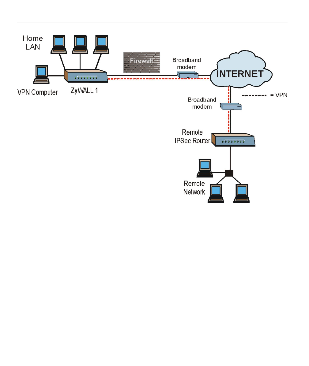
1.3 ZyWALL Application
Connect the ZyWALL to the Internet via a broadband modem. A typical Internet access application is shown
next. One computer on the LAN can use a VPN tunnel from the ZyWALL to a remote IPSec router.
Getting to Know Your ZyWALL 1-3
ZyWALL 1
Figure 1-1 Internet Access Application
1-4 Getting to Know Your ZyWALL
Hardware Installation
This chapter shows you how to connect hardware and perform the initial setup.
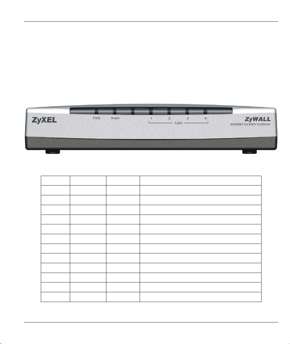
2.1 ZyWALL Front Panel
The LEDs on the front panel indicate the operational status of the ZyWALL.
Figure 2-1 Front Panel
The following table describes ZyWALL LED functions.
LED COLOR STATUS DESCRIPTION
PWR Green On The ZyWALL is on and receiving power.
Off The ZyWALL is not receiving power.
Flashing The ZyWALL is performing a self-test.
WAN Green On The WAN link is connected.
Off The WAN link is not ready, or has failed.
Flashing The 10M WAN link is sending/receiving packets.
LAN 1-4 Green On The ZyWALL is connected to a 10M LAN.
Off The 10M LAN is not connected.
Flashing The 10M LAN is sending/receiving packets.
Orange On The ZyWALL is connected to a 100Mbps LAN.
Off The 100M LAN is not connected.
Flashing The 100M LAN is sending/receiving packets.
ZyWALL 1
Chapter 2
Hardware Installation 2-1
ZyWALL 1
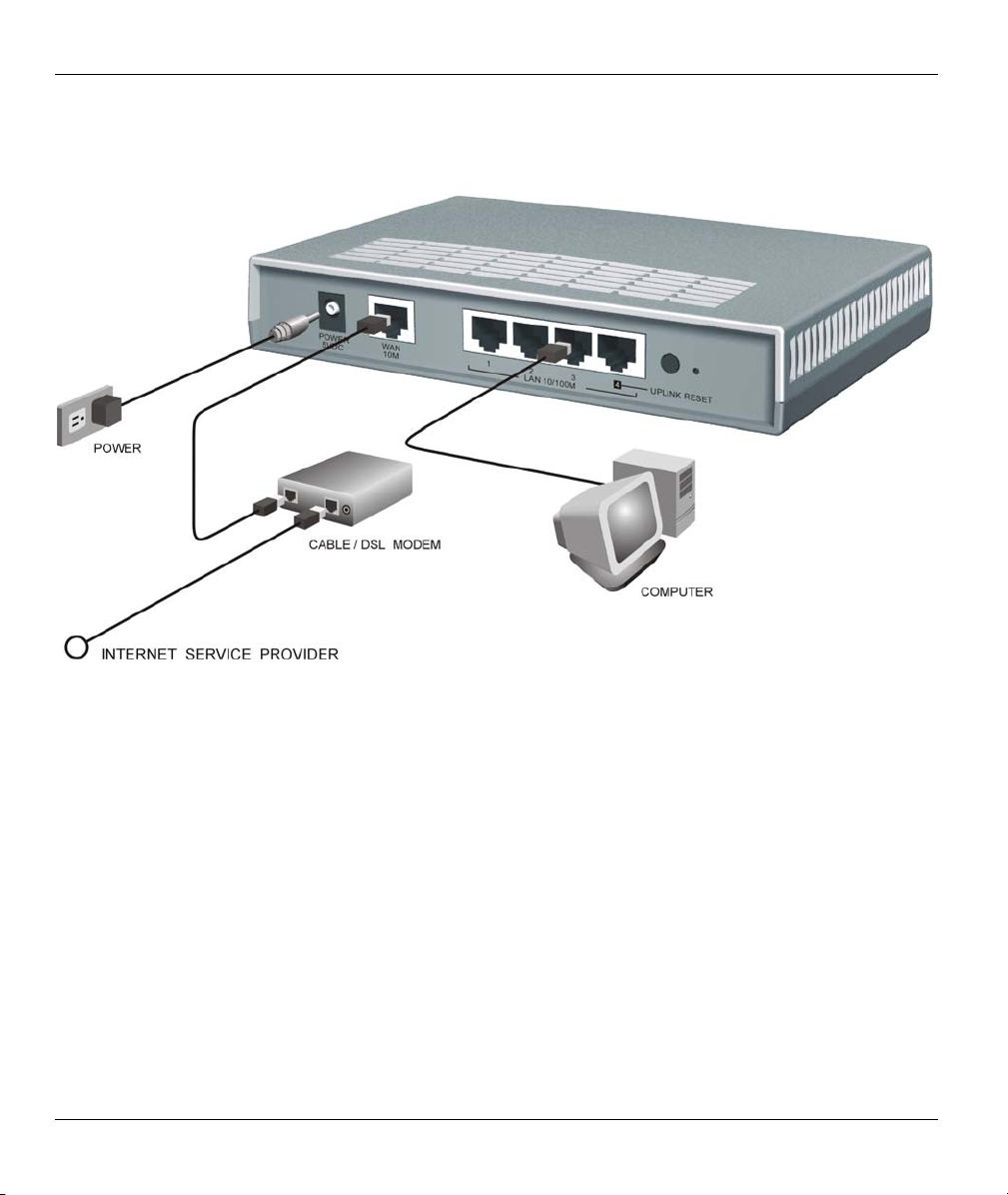
2.2 ZyWALL Rear Panel and Connections
The following figure shows the rear panel of your ZyWALL.
Figure 2-2 Rear Panel
2.2.1 WAN 10M Port
The WAN connection cable should be STP (Shielded Twisted Pair).
Connecting the ZyWALL to a Cable Modem
Connect the WAN 10M port on the ZyWALL to the Ethernet port on your cable modem using the Ethernet
cable that came with your cable modem. The Ethernet port on a cable modem is sometimes labeled "PC" or
"Workstation".
Connecting the ZyWALL to a DSL Modem
Connect the WAN 10M port on the ZyWALL to the Ethernet port on your DSL modem using the Ethernet
cable that came with your DSL modem.
2-2 Hardware Installation

ZyWALL 1
2.2.2 LAN 10/100M 1-4 Ports
You can connect up to four computers directly to the ZyWALL. For each computer, connect a 10/100M LAN
port on the ZyWALL to the Network Adapter on the computer using a straight-through Ethernet cable.
If you want to connect more than three computers to your ZyWALL, you must use an external hub. Connect
a 10/100M LAN port on the ZyWALL to a port on the hub using a crossover Ethernet cable.
When the ZyWALL is on and correctly connected to a computer or hub, the corresponding LAN LED on the
front panel will turn on.
2.2.3 POWER 5VDC Port
Connect the round end of the power adapter to the port labeled POWER 5VDC on the rear
panel of your ZyWALL.
To avoid damage to the ZyWALL, make sure you use the correct power adapter.
Refer to the Power Adapter Specification Appendix for this information.
2.2.4 RESET Button
If you have forgotten your password or cannot access the ZyWALL you will need to use the RESET button
on the rear panel of the ZyWALL to reload the factory-default configuration file. Uploading the
configuration file replaces the current configuration file with the default configuration file and deletes all
previous ZyWALL configurations. The following are the factory defaults for the ZyWALL.
• IP address: 192.168.1.1
• Password: 1234
2.2.5 Procedure To Use The RESET Button
Step 1. Use a pen or pointed object to press the RESET button for 5-10 seconds, then release it.
Step 2. If the LAN LEDs flash within 30 seconds, the factory defaults have been restored and the
ZyWALL restarts. Otherwise, go to step 3.
Step 3. Turn the ZyWALL off.
Step 4. While pressing the RESET button, turn the ZyWALL on.
Step 5. Continue to hold the RESET button for about 30 seconds. The ZyWALL restarts.
Step 6. Release the RESET button and wait for the ZyWALL to finish restarting.
2.3 Additional Installation Requirements
1. A computer(s) with an installed Ethernet NIC (Network Interface Card).
Hardware Installation 2-3

ZyWALL 1
2. A cable/xDSL modem and an ISP account.
2.4 Turning on Your ZyWALL
At this point, you should have connected the LAN port(s), the WAN port and the POWER port to the
appropriate devices or lines. Plug the power adapter into an appropriate power source.
The PWR LED turns on. The WAN LED and the LAN LED (s) turn on after the system tests are complete if
proper connections have been made to the LAN and WAN ports.
2.5 ZyWALL Configuration
2.5.1 Using the Web Configurator
The quickest and easiest way to configure the ZyWALL is via the web configurator. Some configuration
options are available using FTP/TFTP (for example, you can use FTP to upload firmware) and CI commands,
but the web configurator is by far the most comprehensive and user-friendly way to configure your
ZyWALL.
2.5.2 Using FTP/TFTP
Refer to the Firmware and Configuration File Maintenance Commands chapter to learn how to upload
firmware and configuration files using FTP/TFTP.
2.5.3 Using CI Commands
CI commands are recommended for advanced users only. Refer to the support notes for a list of CI
commands.
2-4 Hardware Installation
ZyWALL 1
Chapter 3
Introducing the Web Configurator
This chapter describes how to access the ZyWALL web configurator and provides an overview of
its screens.
3.1 Accessing the ZyWALL Web Configurator
Step 1. Make sure your ZyWALL hardware is properly connected (refer to instructions in Chapter 2).
Step 2. Prepare your computer/computer network to connect to the ZyWALL (refer to the Quick Start
Guide).
Step 3. Launch your web browser.
Step 4. Type "192.168.1.1" as the URL.
Step 5. Type "1234" (default) as the password and click Login. In some versions, the default password
appears automatically - if this is the case, click Login.
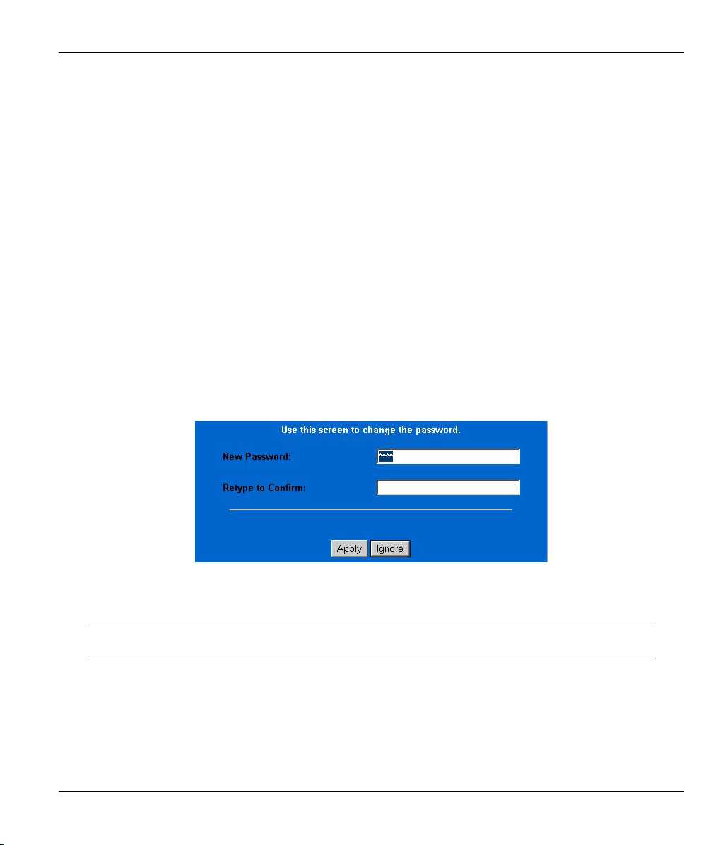
Step 6. You should see a screen asking you to change your password (highly recommended) as shown
next. Type a new password (and retype it to confirm) and click Apply or click Ignore.
Figure 3-1 Change Password Screen
Step 7. You should now see the MAIN MENU screen.
The ZyWALL automatically times out after five minutes of inactivity. Simply log
back into the ZyWALL if this happens to you.
3.2 Navigating the ZyWALL Web Configurator
Introducing the Web Configurator 3-1
ZyWALL 1
A
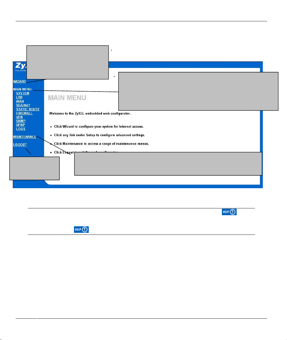
The following summarizes how to navigate the web configurator from the MAIN MENU screen.
Click WIZARD for initial
configuration including general
setup, ISP parameters for Internet
ccess and WAN IP/DNS
Server/MAC address assignment.
Use these links to configure features such as SYSTEM (General Setup,
Dynamic DNS, Password, Time Zone), LAN (DHCP Setup, TCP/IP Setup),
WAN (ISP, IP, MAC), SUA/NAT, STATIC ROUTE (Route Entry), UPNP,
SNMP, FIREWALL (Firewall Settings, Content Filtering, Service Blocking)
VPN/IPSec (Setup, Monitor) and Logs (View Log, Log settings).
Click LOGOUT at
any time to exit the
web configurator.
Click MAINTENANCE to view information about your ZyWALL or upgrade
configuration/firmware files. Maintenance includes SYSTEM STATUS (Statistics), DHCP
TABLE, F/W (firmware) UPGRADE and CONFIGURATION (Backup, Restore Default).
Figure 3-2 The MAIN MENU Screen of the Web Configurator
Follow the instructions you see in the MAIN MENU screen or click the
(located in the top right corner of most screens) to view embedded help.
The
icon does not appear in the MAIN MENU screen.
If you forget your password, refer to section 2.2.4 to reset the default configuration file.
3.3 Overview of the ZyWALL Web Configurator
The following figure illustrates an overview of the features of the web configurator.
icon
3-2 Introducing the Web Configurator

ZyWALL 1
Figure 3-3 Overview of the ZyWALL Web Configurator
Introducing the Web Configurator 3-3


ZyWALL 1
Chapter 4
Wizard Setup
This chapter provides information on the Wizard Setup screens in the web configurator.
4.1 Introduction to Wizard Screens
The Wizard consists of three screens to help you configure your device to access the Internet. The second
screen has three variations depending on what encapsulation type you use. Refer to your ISP checklist in the
Quick Start Guide to know what to enter in each field. Leave a field blank if you don’t have that information.
4.1.1 General Setup and System Name
General Setup contains administrative and system-related information. System Name is for identification
purposes. However, because some ISPs check this name you should enter your computer's "Computer
Name".
• In Windows 95/98 click Start, Settings, Control Panel, Network. Click the Identification tab, note the
entry for the Computer Name field and enter it as the System Name.
• In Windows 2000, click Start, Settings, Control Panel and then double-click System. Click the
Network Identification tab and then the Properties button. Note the entry for the Computer name
field and enter it as the System Name.
• In Windows XP, click Start, My Computer, View system information and then click the Computer
Name tab. Note the entry in the Full computer name field and enter it as the ZyWALL System Name.
4.1.2 Domain Name
The Domain Name entry is what is propagated to the DHCP clients on the LAN. If you leave this blank, the
domain name obtained by DHCP from the ISP is used. While you must enter the host name (System Name)
on each individual computer, the domain name can be assigned from the ZyWALL via DHCP.
Click Next to configure the ZyWALL for Internet access.
Wizard Setup 4-1

ZyWALL 1
Figure 4-1 Wizard 1
4.2 Wizard Setup: Screen 2
The ZyWALL offers three choices of encapsulation. They are Ethernet, PPTP or PPPoE.
4.2.1 Ethernet
Choose Ethernet when the WAN port is used as a regular Ethernet.
4-2 Wizard Setup

Table 4-1 Wizard 2: Ethernet Encapsulation
ZyWALL 1
Table 4-2 Ethernet Encapsulation
FIELD
DESCRIPTION
ISP Parameters for Internet Access
Encapsulation
Service Type
User Name Type the user name given to you by your ISP.
Password Type the password associated with the user name above.
You must choose the Ethernet option when the WAN port is used as a regular
Ethernet. Otherwise, choose PPPoE or PPTP for a dial-up connection.
Choose from Standard or RR login. Choose RoadRunner flavor if your ISP is
Time Warner's RoadRunner; otherwise choose Standard. The User Name,
Password and Login Server IP Address fields are not applicable (N/A) for the
latter.
Wizard Setup 4-3

ZyWALL 1
FIELD
Table 4-2 Ethernet Encapsulation
DESCRIPTION
Login Server IP
Address
Login Server (Telia
Login only)
Relogin Period (min)
(Telia Login only)
To continue, click Next.
To return to the previous screen, click Back.
Type the authentication server IP address here if your ISP gave you one.
Type the domain name of the Telia login server, for example “login1.telia.com”.
The Telia server logs the ZyWALL out if the ZyWALL does not log in periodically.
Type the number of minutes from 1 to 59 (30 default) for the ZyWALL to wait
between logins.
4.2.2 PPTP Encapsulation
Point-to-Point Tunneling Protocol (PPTP) is a network protocol that enables transfers of data from a remote
client to a private server, creating a Virtual Private Network (VPN) using TCP/IP-based networks.
PPTP supports on-demand, multi-protocol, and virtual private networking over public networks, such as the
Internet.
Refer to the appendices for more information on PPTP.
4-4 Wizard Setup

The ZYWALL supports one PPTP server connection at any given time.
ZyWALL 1
Figure 4-2 Wizard 2: PPTP Encapsulation
Table 4-3 PPTP Encapsulation
FIELD DESCRIPTION
ISP Parameters for Internet Access
Encapsulation
User Name Type the user name given to you by your ISP.
Select PPTP from the drop-down list box.
Wizard Setup 4-5

ZyWALL 1
Table 4-3 PPTP Encapsulation
FIELD DESCRIPTION
Password Type the password associated with the User Name above.
Nailed Up
Connection
Idle Timeout
PPTP Configuration
My IP Address Type the (static) IP address assigned to you by your ISP.
My IP Subnet Mask Type the subnet mask assigned to you by your ISP (if given).
Server IP Address Type the IP address of the PPTP server.
Connection
ID/Name
To continue, click Next.
To return to the previous screen, click Back.
Select Nailed Up Connection if you do not want the connection to time out.
Type the time in seconds that elapses before the router automatically disconnects from
the PPTP server. The default is 45 seconds.
Enter the connection ID or connection name in this field. It must follow the "c:id" and
"n:name" format. For example, C:12 or N:My ISP.
This field is optional and depends on the requirements of your xDSL modem.
4.2.3 PPPoE Encapsulation
Point-to-Point Protocol over Ethernet (PPPoE) functions as a dial-up connection. PPPoE is an IETF (Internet
Engineering Task Force) draft standard specifying how a host personal computer interacts with a broadband
modem (for example xDSL, cable, wireless, etc.) to achieve access to high-speed data networks. It preserves
the existing Microsoft Dial-Up Networking experience and requires no new learning or procedures.
For the service provider, PPPoE offers an access and authentication method that works with existing access
control systems (for instance, Radius). For the user, PPPoE provides a login and authentication method that
the existing Microsoft Dial-Up Networking software can activate, and therefore requires no new learning or
procedures for Windows users.
One of the benefits of PPPoE is the ability to let end users access one of multiple network services, a function
known as dynamic service selection. This enables the service provider to easily create and offer new IP
services for specific users.
Operationally, PPPoE saves significant effort for both the subscriber and the ISP/carrier, as it requires no
specific configuration of the broadband modem at the subscriber’s site.
By implementing PPPoE directly on the ZyWALL (rather than individual computers), the computers on the
LAN do not need PPPoE software installed, since the ZyWALL does that part of the task. Furthermore, with
NAT, all of the LAN's computers will have Internet access.
4-6 Wizard Setup

Refer to the appendices for more information on Pope.
ZyWALL 1
Figure 4-3 Wizard2: PPPoE Encapsulation
Table 4-4 PPPoE Encapsulation
FIELD DESCRIPTION
ISP Parameter for Internet Access
Encapsulation
Service Name
(Optional)
User Name Type the user name given to you by your ISP.
Password Type the password associated with the user name above.
Choose an encapsulation method from the pull-down list box. PPPoE forms a dial-up
connection.
Type the name of your service provider.
Wizard Setup 4-7

ZyWALL 1
Table 4-4 PPPoE Encapsulation
FIELD DESCRIPTION
Nailed Up
Connection
Idle Timeout
To continue, click Next.
To return to the previous screen, click Back.
Select Nailed Up Connection if you do not want the connection to time out.
Type the time in seconds that elapses before the router automatically disconnects from
the PPPoE server. The default time is 100 seconds.
4.3 Wizard Setup: Screen 3
4.3.1 WAN IP Address Assignment
Every computer on the Internet must have a unique IP address. If your networks are isolated from the
Internet, for instance, only between your two branch offices, you can assign any IP addresses to the hosts
without problems. However, the Internet Assigned Numbers Authority (IANA) has reserved the following
three blocks of IP addresses specifically for private networks.
Table 4-5 Private IP Address Ranges
10.0.0.0 - 10.255.255.255
172.16.0.0 - 172.31.255.255
192.168.0.0 - 192.168.255.255
You can obtain your IP address from the IANA, from an ISP or have it assigned by a private network. If you
belong to a small organization and your Internet access is through an ISP, the ISP can provide you with the
Internet addresses for your local networks. On the other hand, if you are part of a much larger organization,
you should consult your network administrator for the appropriate IP addresses.
4-8 Wizard Setup

ZyWALL 1
Regardless of your particular situation, do not create an arbitrary IP address;
always follow the guidelines above. For more information on address assignment,
please refer to RFC 1597, Address Allocation for Private Internets and RFC 1466,
Guidelines for Management of IP Address Space.
4.3.2 IP Address and Subnet Mask
Similar to the way houses on a street share a common street name, so too do computers on a LAN share one
common network number.
Where you obtain your network number depends on your particular situation. If the ISP or your network
administrator assigns you a block of registered IP addresses, follow their instructions in selecting the IP
addresses and the subnet mask.
If the ISP did not explicitly give you an IP network number, then most likely you have a single user account
and the ISP will assign you a dynamic IP address when the connection is established. If this is the case, it is
recommended that you select a network number from 192.168.0.0 to 192.168.255.0 and you must enable the
Network Address Translation (NAT) feature of the ZyWALL. The Internet Assigned Number Authority
(IANA) reserved this block of addresses specifically for private use; please do not use any other number
unless you are told otherwise. Let's say you select 192.168.1.0 as the network number; which covers 254
individual addresses, from 192.168.1.1 to 192.168.1.254 (zero and 255 are reserved). In other words, the first
three numbers specify the network number while the last number identifies an individual computer on that
network.
Once you have decided on the network number, pick an IP address that is easy to remember, for instance,
192.168.1.1, for your ZyWALL, but make sure that no other device on your network is using that IP address.
The subnet mask specifies the network number portion of an IP address. Your ZyWALL will compute the
subnet mask automatically based on the IP address that you entered. You don't need to change the subnet
mask computed by the ZyWALL unless you are instructed to do otherwise.
4.3.3 DNS Server Address Assignment
Use DNS (Domain Name System) to map a domain name to its corresponding IP address and vice versa, for
instance, the IP address of www.zyxel.com is 204.217.0.2. The DNS server is extremely important because
without it, you must know the IP address of a computer before you can access it.
There are two ways that an ISP disseminates the DNS server addresses.
1. The ISP tells you the DNS server addresses, usually in the form of an information sheet, when you sign
up. If your ISP gives you DNS server addresses, enter them in the DNS Server fields in DHCP Setup.
2. Leave the DNS Server fields in DHCP Setup blank (for example 0.0.0.0). The ZyWALL acts as a DNS
proxy when this field is blank.
Wizard Setup 4-9

ZyWALL 1
4.3.4 WAN MAC Address
Every Ethernet device has a unique MAC (Media Access Control) address. The MAC address is assigned at
the factory and consists of six pairs of hexadecimal digits, for example, 00:A0:C5:00:00:02.
You can configure the WAN port's MAC address by either using the factory default or cloning the MAC
address from a workstation on your LAN. Once it is successfully configured, the address will be copied to
the "rom" file (ZyNOS configuration file). It will not change unless you change the setting or upload a
different "rom" file.
ZyXEL recommends you clone the MAC address from a workstation on your LAN
even if your ISP does not require MAC address authentication.
Your ZyWALL WAN Port is always set at half-duplex mode as most cable/DSL modems only support halfduplex mode. Make sure your modem is in half-duplex mode. Your ZyWALL supports full duplex mode on
the LAN side.
Table 4-6 Example of Network Properties for LAN Servers with Fixed IP Addresses
Choose an IP address 192.168.1.2-192.168.1.32; 192.168.1.65-192.168.1.254.
Subnet mask 255.255.255.0
Gateway (or default route) 192.168.1.1(ZyWALL LAN IP)
4-10 Wizard Setup

ZyWALL 1
Figure 4-4 Wizard 3
Table 4-7 WAN Setup
FIELD
WAN IP Address Assignment
Get automatically from
Use fixed IP address Select this option If the ISP assigned a fixed IP address.
IP Subnet Mask
Gateway IP Address
DNS Server Address Assignment
DESCRIPTION
Select this option If your ISP did not assign you a fixed IP address. This is the
ISP
default selection.
IP Address
Enter your WAN IP address in this field if you selected Use Fixed IP Address.
Enter the IP subnet mask in this field if you selected Use Fixed IP Address.
Enter the gateway IP address in this field if you selected Use Fixed IP Address.
Wizard Setup 4-11

ZyWALL 1
Table 4-7 WAN Setup
FIELD
Get automatically from
Use fixed IP address -
DNS Server IP Address
Primary/Secondary DNS
WAN MAC Address
Spoof this Computer's
MAC address - IP
To return to the previous screen, click Back.
To complete and save the wizard setup, click Finish.
DESCRIPTION
Select this option if your ISP does not give you DNS server addresses. This
ISP
option is selected by default.
Select this option If your ISP provides you a DNS server address.
If you selected the Use fixed IP address – Primary/Secondary DNS Server
Server
option, enter the provided DNS addresses in these fields.
The MAC address field allows you to configure the WAN port's MAC Address by
either using the factory default or cloning the MAC address from a workstation on
your LAN.
Factory Default Select this option to use the factory assigned default MAC Address.
Select this option and enter the IP address of the computer on the LAN whose
MAC you are cloning. Once it is successfully configured, the address will be
copied to the rom file (ZyNOS configuration file). It will not change unless you
Address
change the setting or upload a different rom file. It is advisable to clone the MAC
address from a computer on your LAN even if your ISP does not presently
require MAC address authentication.
4.4 Basic Setup Complete
Well done! You have successfully set up your ZyWALL to operate on your network and access the Internet.
4-12 Wizard Setup

Advanced Menus
Part II:
Advanced
This part covers System, LAN, WAN, SUA/NAT, Static Route, UPnP and SNMP.
II


ZyWALL 1
Chapter 5
System
This chapter provides information on the System screens in the web configurator.
5.1 About System Setup
See the Wizard Setup chapter for more information on the next few screens.
5.2 General Setup
From the MAIN MENU, click SYSTEM. The screen appears as shown next. This is the screen for the
General tab.
Figure 5-1 System General Setup
Table 5-1 System General Setup
FIELD DESCRIPTION EXAMPLE
System Name Choose a descriptive name for identification purposes. It is
recommended you enter your computer’s “Computer name” in this
field (see the Wizard Setup chapter for how to find your computer’s
name). This name can be up to 30 alphanumeric characters long.
Spaces are not allowed, but dashes “-” and underscores "_" are
accepted.
System 5-1
MyComputer

ZyWALL 1
Table 5-1 System General Setup
FIELD DESCRIPTION EXAMPLE
Domain Name Enter the domain name (if you know it) here. If you leave this field
blank, the ISP may assign a domain name via DHCP.
The domain name entered by you is given priority over the ISP
assigned domain name.
Administrator
Inactivity Timer
Click Apply to save your changes back to the ZyWALL.
Click Reset to begin configuring this screen afresh.
Type how many minutes a management session can be left idle
before the session times out. The default is 5 minutes. After it times
out you have to log in with your password again. Very long idle
timeouts may have security risks. A value of "0" means a
management session never times out, no matter how long it has
been left idle (not recommended).
zyxel.com.tw
5
5.3 Dynamic DNS
Dynamic DNS allows you to update your current dynamic IP address with one or many dynamic DNS
services so that anyone can contact you (in NetMeeting, CU-SeeMe, etc.). You can also access your FTP
server or Web site on your own computer using a DNS-like address (for instance myhost.dhs.org, where
myhost is a name of your choice) that will never change instead of using an IP address that changes each
time you reconnect. Your friends or relatives will always be able to call you even if they don't know your IP
address.
First of all, you need to have registered a dynamic DNS account with www.dyndns.org. This is for people
with a dynamic IP from their ISP or DHCP server that would still like to have a DNS name. The Dynamic
DNS service provider will give you a password or key.
5.3.1 DYNDNS Wildcard
Enabling the wildcard feature for your host causes *.yourhost.dyndns.org to be aliased to the same IP address
as yourhost.dyndns.org. This feature is useful if you want to be able to use, for example,
www.yourhost.dyndns.org and still reach your hostname.
If you have a private WAN IP address, then you cannot use Dynamic DNS.
5.3.2 Procedure To Configure Dynamic DNS
From the MAIN MENU, click SYSTEM and DDNS.
5-2 System

ZyWALL 1
Figure 5-2 System DDNS
Table 5-2 System DDNS
FIELD DESCRIPTION EXAMPLE
Active Select this check box to use dynamic DNS.
Service Provider Select the name of your Dynamic DNS service provider. www.dyndns.org
DDNS Type Select the type of service that you are registered for from your
Dynamic DNS service provider.
Host Names 1~3 Enter the host names in the three fields provided. You can specify
up to two host names in each field separated by a comma (",").
E-Mail Address Enter the e-mail address of the host in this field.
User Enter your user name. Joe
Password Enter the password assigned to you.
System 5-3

ZyWALL 1
Table 5-2 System DDNS
FIELD DESCRIPTION EXAMPLE
Enable Wildcard Select the check box to enable DYNDNS Wildcard.
Off Line
Edit Update IP Address
Server Auto
User Specify Select this option to update the IP address of the host name(s) to
IP Addr
Click Apply to save your changes back to the ZyWALL.
Click Reset to begin configuring this screen afresh.
This option is available when CustomDNS is selected in the
DDNS Type field. Check with your Dynamic DNS service provider
to have traffic redirected to a URL (that you can specify) while you
are off line.
Select this option to update the IP address of the host name(s)
Detect
automatically by the DDNS server.
the IP address specified below. Use this option if you have a static
IP address.
Enter the IP address if you select the User Specify option.
5.4 Password
To change your ZyWALL’s password (recommended), click SYSTEM, then the Password tab. The screen
appears as shown. This screen allows you to change the ZyWALL’s password.
Figure 5-3 System Password
5-4 System

ZyWALL 1
Table 5-3 System Password
FIELD DESCRIPTION
Old Password Type the default password or the existing password you use to access the system
in this field.
New Password Type the new password in this field.
Retype to Confirm Type the new password again in this field.
Click Apply to save your changes back to the ZyWALL.
Click Reset to begin configuring this screen afresh.
5.5 Time Zone
To change your ZyWALL’s time and date, click SYSTEM, then the Time Zone tab. The screen appears as
shown. Use this screen to configure the ZyWALL’s time based on your local time zone.
Figure 5-4 System Time/Date
System 5-5

ZyWALL 1
Table 5-4 System Time/Date
FIELD DESCRIPTION
Use Time
Server when
Bootup
Enter the time service protocol that your time server sends when you turn on the
ZyWALL. Not all time servers support all protocols, so you may have to check with your
ISP/network administrator or use trial and error to find a protocol that works. The main
differences between them are the format.
Daytime (RFC 867) format is day/month/year/time zone of the server.
Time (RFC-868) format displays a 4-byte integer giving the total number of seconds
since 1970/1/1 at 0:0:0.
NTP (RFC-1305) is similar to Time (RFC-868).
None. If you chose None, then you need to enter the time manually.
Time Server IP
Address
Current Time This field displays an updated time only when you reenter this menu.
New Time Enter the new time in hour, minute and second format.
Current Date This field displays an updated date only when you re-enter this menu.
New Date Enter the new date in year, month and day format.
Time Zone Select your time zone from the pull down list.
Daylight
Savings
Start Date
End Date
Click Apply to save your changes back to the ZyWALL.
Click Reset to begin configuring this screen afresh.
Enter the IP address or domain name of your time server. Check with your ISP/network
administrator if you are unsure of this information.
Select this option if you use daylight savings time. Daylight saving is a period from late
spring to early fall when many countries set their clocks ahead of normal local time by one
hour to give more daytime light in the evening.
Enter the month and day that your daylight-savings time starts on if you selected Daylight
Savings.
Enter the month and day that your daylight-savings time ends on if you selected Daylight
Savings.
5-6 System

ZyWALL 1
Chapter 6
LAN and WAN
This chapter describes how to configure LAN and WAN settings using the web configurator.
6.1 DHCP Setup
DHCP (Dynamic Host Configuration Protocol, RFC 2131 and RFC 2132) allows individual clients to obtain
TCP/IP configuration at start-up from a server. You can configure the ZyWALL as a DHCP server or disable
it. When configured as a server, the ZyWALL provides the TCP/IP configuration for the clients. If set to
None, DHCP service will be disabled and you must have another DHCP server on your LAN, or else the
computer must be manually configured.
6.1.1 IP Pool Setup
The ZyWALL is pre-configured with a pool of 32 IP addresses starting from 192.168.1.33 to 192.168.1.64.
This configuration leaves 31 IP addresses (excluding the ZyWALL itself) in the lower range for other server
computers, for instance, servers for mail, FTP, TFTP, web, etc., that you may have.
6.1.2 Primary and Secondary DNS Server
Refer to the IP Address and Subnet Mask section in the Wizard Setup chapter.
6.2 LAN TCP/IP
The ZyWALL has built-in DHCP server capability that assigns IP addresses and DNS servers to systems that
support DHCP client capability.
6.2.1 Factory LAN Defaults
The LAN parameters of the ZyWALL are preset in the factory with the following values:
Step 1. IP address of 192.168.1.1 with subnet mask of 255.255.255.0 (24 bits)
Step 2. DHCP server enabled with 32 client IP addresses starting from 192.168.1.33.
These parameters should work for the majority of installations. If your ISP gives you explicit DNS server
address(es), read the embedded web configurator help regarding what fields need to be configured.
6.2.2 IP Address and Subnet Mask
Refer to the IP Address and Subnet Mask section in the Wizard Setup chapter for this information.
LAN and WAN 6-1

ZyWALL 1
6.2.3 RIP Setup
RIP (Routing Information Protocol, RFC 1058 and RFC 1389) allows a router to exchange routing
information with other routers. RIP Direction controls the sending and receiving of RIP packets. When set
to Both or Out Only, the ZyWALL will broadcast its routing table periodically. When set to Both or In
Only, it will incorporate the RIP information that it receives; when set to None, it will not send any RIP
packets and will ignore any RIP packets received.
RIP Version controls the format and the broadcasting method of the RIP packets that the ZyWALL sends
(it recognizes both formats when receiving). RIP-1 is universally supported; but RIP-2 carries more
information. RIP-1 is probably adequate for most networks, unless you have an unusual network topology.
Both RIP-2B and RIP-2M send routing data in RIP-2 format; the difference being that RIP-2B uses subnet
broadcasting while RIP-2M uses multicasting. Multicasting can reduce the load on non-router machines
since they generally do not listen to the RIP multicast address and so will not receive the RIP packets.
However, if one router uses multicasting, then all routers on your network must use multicasting, also.
By default, RIP Direction is set to Both and RIP Version to RIP-1.
6.2.4 Multicast
Traditionally, IP packets are transmitted in one of either two ways - Unicast (1 sender - 1 recipient) or
Broadcast (1 sender - everybody on the network). Multicast delivers IP packets to a group of hosts on the
network - not everybody and not just 1.
IGMP (Internet Group Multicast Protocol) is a network-layer protocol used to establish membership in a
Multicast group - it is not used to carry user data. IGMP version 2 (RFC 2236) is an improvement over
version 1 (RFC 1112) but IGMP version 1 is still in wide use. If you would like to read more detailed
information about interoperability between IGMP version 2 and version 1, please see sections 4 and 5 of
RFC 2236. The class D IP address is used to identify host groups and can be in the range 224.0.0.0 to
239.255.255.255. The address 224.0.0.0 is not assigned to any group and is used by IP multicast computers.
The address 224.0.0.1 is used for query messages and is assigned to the permanent group of all IP hosts
(including gateways). All hosts must join the 224.0.0.1 group in order to participate in IGMP. The address
224.0.0.2 is assigned to the multicast routers group.
The ZyWALL supports both IGMP version 1 (IGMP-v1) and IGMP version 2 (IGMP-v2). At start up, the
ZyWALL queries all directly connected networks to gather group membership. After that, the ZyWALL
periodically updates this information. IP multicasting can be enabled/disabled on the ZyWALL LAN and/or
WAN interfaces in the web configurator (LAN; WAN). Select None to disable IP multicasting on these
interfaces.
6-2 LAN and WAN

ZyWALL 1
Figure 6-1 LAN Setup
Table 6-1 LAN Setup
FIELD DESCRIPTION
DHCP Server
IP Pool Starting
Address
Pool Size This field specifies the size, or count of the IP address pool.
Primary DNS Server
Secondary DNS
LAN TCP/IP
This field enables/disables the DHCP server. Select DHCP Server to have your
ZyWALL act as a DHCP server; otherwise, the DHCP server will be disabled.
When enabled, the following items need to be set:
This field specifies the first of the contiguous addresses in the IP address pool.
Type the IP addresses of the DNS servers. The DNS servers are passed to the DHCP
clients along with the IP address and the subnet mask.
Server
LAN and WAN 6-3

ZyWALL 1
Table 6-1 LAN Setup
FIELD DESCRIPTION
IP Address Enter the IP address of your ZyWALL in dotted decimal notation
IP Subnet Mask Your ZyWALL will automatically calculate the subnet mask based on the IP address that
you assign. Unless you are implementing subnetting, use the subnet mask computed by
the ZyWALL.
RIP Direction RIP (Routing Information Protocol, RFC1058 and RFC 1389) allows a router to
exchange routing information with other routers. The RIP Direction field controls the
sending and receiving of RIP packets. Select the RIP direction from Both/In Only/Out
Only/None. When set to Both or Out Only, the ZyWALL will broadcast its routing table
periodically. When set to Both or In Only, it will incorporate the RIP information that it
receives; when set to None, it will not send any RIP packets and will ignore any RIP
packets received. Both is the default.
RIP Version
Multicast IGMP (Internet Group Multicast Protocol) is a network-layer protocol used to establish
Windows Networking (NetBIOS) Broadcast Pass Through: NetBIOS (Network Basic Input/Output System) are
TCP or UDP broadcast packets that enable a computer to connect to and communicate with a LAN.
For some dial-up services such as PPPoE or PPTP, NetBIOS packets cause unwanted calls. However it may
sometimes be necessary to allow NetBIOS packets to pass through to the WAN in order to find a computer on
the WAN.
From LAN to WAN Select this check box to allow NetBIOS packets to pass through to the WAN in order to
Click Apply to save your changes back to the ZyWALL.
Click Reset to begin configuring this screen afresh.
The RIP Version field controls the format and the broadcasting method of the RIP
packets that the ZyWALL sends (it recognizes both formats when receiving). RIP-1 is
universally supported but RIP-2 carries more information. RIP-1 is probably adequate
for most networks, unless you have an unusual network topology. Both RIP-2B and
RIP-2M sends the routing data in RIP-2 format; the difference being that RIP-2B uses
subnet broadcasting while RIP-2M uses multicasting. Multicasting can reduce the load
on non-router machines since they generally do not listen to the RIP multicast address
and so will not receive the RIP packets. However, if one router uses multicasting, then
all routers on your network must use multicasting, also. By default, RIP direction is set
to Both and the Version set to RIP-1.
membership in a Multicast group. The ZyWALL supports both IGMP version 1 (IGMP-
v1) and version 2 (IGMP-v2).
find a computer on the WAN.
6-4 LAN and WAN

ZyWALL 1
6.3 WAN Setup
To configure the WAN, click WAN from the MAIN MENU. For more information, refer to the chapter on
Wizard Setup.
6.3.1 WAN Setup: ISP
Ethernet Encapsulation
Click the ISP tab. The screen shown next is for Ethernet encapsulation. The screen differs by the
encapsulation.
Figure 6-2 Ethernet Encapsulation
Table 6-2 Ethernet Encapsulation
FIELD DESCRIPTION
Encapsulation You must choose the Ethernet option when the WAN port is used as a regular Ethernet.
Service Type
User Name Type the user name given to you by your ISP.
Choose from Standard, Telstra (RoadRunner Telstra authentication method), RR-Manager
(Roadrunner Manager authentication method), RR-Toshiba (Roadrunner Toshiba
authentication method) or Telia Login.
The following fields do not appear with the Standard service type.
LAN and WAN 6-5

ZyWALL 1
Table 6-2 Ethernet Encapsulation
FIELD DESCRIPTION
Password Type the password associated with the user name above.
Login Server
IP Address
Login Server
(Telia Login
only)
Relogin Period
(min) (Telia
Login only)
Click Apply to save your changes back to the ZyWALL.
Click Reset to begin configuring this screen afresh.
Type the authentication server IP address here if your ISP gave you one.
Type the domain name of the Telia login server, for example “login1.telia.com”.
The Telia server logs the ZyWALL out if the ZyWALL does not log in periodically. Type the
number of minutes from 1 to 59 (30 default) for the ZyWALL to wait between logins.
PPPoE Encapsulation
The screen shown next is for PPPoE encapsulation.
Figure 6-3 PPPoE Encapsulation
6-6 LAN and WAN

ZyWALL 1
Table 6-3 PPPoE Encapsulation
FIELD DESCRIPTION
ISP Parameters for Internet Access
Encapsulation The PPPoE choice is for a dial-up connection using PPPoE. The router supports PPPoE
(Point-to-Point Protocol over Ethernet). PPPoE is an IETF Draft standard (RFC 2516)
specifying how a personal computer (PC) interacts with a broadband modem (i.e. xDSL,
cable, wireless, etc.) connection. Operationally, PPPoE saves significant effort for both the
end user and ISP/carrier, as it requires no specific configuration of the broadband modem at
the customer site. By implementing PPPoE directly on the router rather than individual
computers, the computers on the LAN do not need PPPoE software installed, since the
router does that part of the task. Further, with NAT, all of the LAN's computers will have
access.
Service Name Type the PPPoE service name provided to you. PPPoE uses a service name to identify and
reach the PPPoE server.
User Name Type the User Name given to you by your ISP.
Password Type the password associated with the User Name above.
Idle Timeout This value specifies the time in seconds that elapses before the router automatically
disconnects from the PPPoE server.
Click Apply to save your changes back to the ZyWALL.
Click Reset to begin configuring this screen afresh.
PPTP Encapsulation
The screen shown next is for PPTP encapsulation.
LAN and WAN 6-7

ZyWALL 1
Figure 6-4 PPTP Encapsulation
Table 6-4 PPTP Encapsulation
FIELD DESCRIPTION
ISP Parameters for Internet Access
Encapsulation Point-to-Point Tunneling Protocol (PPTP) is a network protocol that enables secure
transfer of data from a remote client to a private server, creating a Virtual Private
Network (VPN) using TCP/IP-based networks. PPTP supports on-demand, multiprotocol, and virtual private networking over public networks, such as the Internet.
The ZyWALL supports only one PPTP server connection at any given time. To
configure a PPTP client, you must configure the My Login and Password fields for a
PPP connection and the PPTP parameters for a PPTP connection.
Service Name Type the PPPoE service name provided to you. PPPoE uses a service name to
identify and reach the PPPoE server.
User Name Type the User Name given to you by your ISP.
Password Type the password associated with the User Name above.
6-8 LAN and WAN

Table 6-4 PPTP Encapsulation
FIELD DESCRIPTION
Idle Timeout This value specifies the time in seconds that elapses before the ZyWALL
automatically disconnects from the PPTP server.
PPTP Encapsulation
My IP Address Type the (static) IP address assigned to you by your ISP.
Server IP Address Type the IP address of the PPTP server.
Connection ID/Name Type your identification name for the PPTP server.
Click Apply to save your changes back to the ZyWALL.
Click Reset to begin configuring this screen afresh.
6.3.2 WAN Setup: IP
Click the IP tab to display the IP Setup screen shown next.
ZyWALL 1
LAN and WAN 6-9

ZyWALL 1
Figure 6-5 IP Setup
Table 6-5 IP Setup
FIELD DESCRIPTION
WAN IP Address Assignment
Get automatically from
ISP
Use fixed IP address Select this option If the ISP assigned a fixed IP address.
IP Address
IP Subnet Mask
Select this option If your ISP did not assign you a fixed IP address. This is the
default selection.
Enter your WAN IP address in this field if you selected Use Fixed IP Address.
Enter the IP subnet mask (if your ISP gave you one) in this field if you selected
Use Fixed IP Address.
6-10 LAN and WAN

Table 6-5 IP Setup
FIELD DESCRIPTION
ZyWALL 1
Gateway IP Address
Network Address
Translation
RIP Direction
RIP Version
Enter the gateway IP address (if your ISP gave you one) in this field if you
selected Use Fixed IP Address.
Network Address Translation (NAT) allows the translation of an Internet protocol
address used within one network to a different IP address known within another
network.
SUA (Single User Account) is a subset of NAT that supports Many-to-One and
Server mappings.
Refer to Chapter 7 for more information about NAT.
RIP (Routing Information Protocol) allows a router to exchange routing
information with other routers. The RIP Direction field controls the sending and
receiving of RIP packets.
Choose Both, None, In Only or Out Only.
When set to Both or Out Only, the ZyWALL will broadcast its routing table
periodically.
When set to Both or In Only, the ZyWALL will incorporate RIP information that it
receives.
When set to None, the ZyWALL will not send any RIP packets and will ignore
any RIP packets received.
By default, RIP Direction is set to Both.
The RIP Version field controls the format and the broadcasting method of the
RIP packets that the ZyWALL sends (it recognizes both formats when receiving).
Choose RIP-1, RIP-2B or RIP-2M.
RIP-1 is universally supported; but RIP-2 carries more information. RIP-1 is
probably adequate for most networks, unless you have an unusual network
topology. Both RIP-2B and RIP-2M sends the routing data in RIP-2 format; the
difference being that RIP-2B uses subnet broadcasting while RIP-2M uses
multicasting. Multicasting can reduce the load on non-router machines since they
generally do not listen to the RIP multicast address and so will not receive the
RIP packets. However, if one router uses multicasting, then all routers on your
network must use multicasting, also. By default, the RIP Version field is set to
RIP-1.
LAN and WAN 6-11

ZyWALL 1
Table 6-5 IP Setup
FIELD DESCRIPTION
Choose None (default), IGMP-V1 or IGMP-V2. IGMP (Internet Group Multicast
Protocol) is a session-layer protocol used to establish membership in a Multicast
Multicast
Windows Networking (NetBIOS over TCP/IP) Pass Through: NetBIOS (Network Basic Input/Output
System) are TCP or UDP broadcast packets that enable a computer to connect to and communicate with a
LAN.
For some dial-up services such as PPPoE or PPTP, NetBIOS packets cause unwanted calls.
Allow From WAN to LAN
group - it is not used to carry user data. IGMP version 2 (RFC 2236) is an
improvement over version 1 (RFC 1112) but IGMP version 1 is still in wide use. If
you would like to read more detailed information about interoperability between
IGMP version 2 and version 1, please see sections 4 and 5 of RFC 2236.
Select this check box to allow NetBIOS packets from the WAN port to the LAN
port.
In order to forward NetBIOS packets from the WAN to the LAN, you must also
configure the SUA/NAT screen for one of the following.
1. (Recommended) Set a port forwarding entry for ports 137 to 139 and another
port forwarding entry for port 445.
2. Set a default server.
Allow Trigger Dial Select this check box to stop NetBIOS packets from initiating calls.
Click Apply to save your changes back to the ZyWALL.
Click Reset to begin configuring this screen afresh.
6.3.3 WAN Setup: MAC
Click on the MAC tab to display the MAC Setup screen shown next.
6-12 LAN and WAN

ZyWALL 1
Figure 6-6 MAC Setup
The MAC address screen allows users to configure the WAN port's MAC Address by either using the factory
default or cloning the MAC address from a computer on your LAN. Choose Factory Default to select the
factory assigned default MAC Address.
Otherwise, click Spoof this computer's MAC address - IP Address and enter the IP address of the
computer on the LAN whose MAC you are cloning. Once it is successfully configured, the address will be
copied to the rom file (ZyNOS configuration file). It will not change unless you change the setting or upload
a different ROM file.
LAN and WAN 6-13


ZyWALL 1
Chapter 7
SUA/NAT
This chapter discusses how to configure SUA/NAT on the ZyWALL
7.1 The SUA/NAT Screen
This section discusses SUA (Single User Account)/NAT (Network Address Translation) applications of the
ZyWALL.
7.1.1 Introduction
SUA (Single User Account) is a ZyNOS implementation of a subset of NAT (Network Address Translation).
7.1.2 The SUA Server Screen
A SUA server set is a list of inside (behind NAT on the LAN) servers, for example, web or FTP, that you can
make visible to the outside world even though SUA makes your whole inside network appear as a single
computer to the outside world.
You may enter a single port number or a range of port numbers to be forwarded, and the local IP address of
the desired server. The port number identifies a service; for example, web service is on port 80 and FTP on
port 21. In some cases, such as for unknown services or where one server can support more than one service
(for example both FTP and web service), it might be better to specify a range of port numbers. You can
allocate a server IP address that corresponds to a port or a range of ports.
Many residential broadband ISP accounts do not allow you to run any server processes (such as a Web or
FTP server) from your location. Your ISP may periodically check for servers and may suspend your account
if it discovers any active services at your location. If you are unsure, refer to your ISP.
Default Server IP Address
In addition to the servers for specified services, NAT supports a default server IP address. A default server
receives packets from ports that are not specified in this screen.
If you do not assign a Default Server IP Address, then all packets received for ports
not specified in this screen will be discarded.
7.1.3 Services and Port Numbers
The most often used port numbers are shown in the following table. Please refer to RFC 1700 for further
information about port numbers. Please also refer to the Supporting CD for more examples and details on
SUA/NAT.
SUA/NAT 7-1

ZyWALL 1
Table 7-1 Services and Port Numbers
SERVICES PORT NUMBER
ECHO 7
FTP (File Transfer Protocol) 21
SMTP (Simple Mail Transfer Protocol) 25
DNS (Domain Name System) 53
Finger 79
HTTP (Hyper Text Transfer protocol or WWW, Web) 80
POP3 (Post Office Protocol) 110
NNTP (Network News Transport Protocol) 119
SNMP (Simple Network Management Protocol) 161
SNMP trap 162
PPTP (Point-to-Point Tunneling Protocol) 1723
7.1.4 Configuring Servers Behind SUA (Example)
Let's say you want to assign ports 22-25 to one server, port 80 to another and assign a default server IP
address of 192.168.1.35 as shown in the next figure.
Figure 7-1 Multiple Servers Behind NAT Example
7-2 SUA/NAT

ZyWALL 1
When you configure NAT port forwarding rules, the firewall automatically allows traffic originating from the
WAN (for the services specified) to be forwarded to the LAN IP address(es) configured here.
If you do not assign a Default Server IP Address, then all packets received for ports
not specified in this screen will be discarded.
Figure 7-2 SUA/NAT Setup
SUA/NAT 7-3

ZyWALL 1
Table 7-2 SUA/NAT Setup
FIELD DESCRIPTION
Default Server In addition to the servers for specified services, NAT supports a default server. A
default server receives packets from ports that are not specified in this screen. If
you do not assign a default server IP address, then all packets received for ports
not specified in this screen will be discarded. Assigning a default server IP
address turns off the firewall protection for that IP address.
# Number of an individual SUA server entry.
Active Select this check box to enable the SUA server entry. Clear this checkbox to
disallow forwarding of these ports to an inside server without having to delete the
entry.
Name Enter a name to identify this port-forwarding rule.
Start Port
End Port
Server IP Address Enter the inside IP address of the server here.
Respond to Ping on
Internet WAN Port
Click Apply to save your changes back to the ZyWALL.
Click Reset to begin configuring this screen afresh.
Enter a port number here. To forward only one port, enter it again in the End Port
field. To specify a range of ports, enter the last port to be forwarded in the End
Port No field
Select the check box to enable a ping response from the Internet WAN port.
Clear the check box to disable a ping response from the Internet WAN port.
7-4 SUA/NAT

ZyWALL 1
Chapter 8
Static Route
This chapter shows you how to configure static routes for your ZyWALL.
8.1 General Information About Static Routes
Each remote node specifies only the network to which the gateway is directly connected, and the ZyWALL
has no knowledge of the networks beyond. For instance, the ZyWALL knows about network N2 in the
following figure through remote node Router 1. However, the ZyWALL is unable to route a packet to
network N3 because it doesn't know that there is a route through the same remote node Router 1 (via gateway
Router 2). The static routes are for you to tell the ZyWALL about the networks beyond the remote nodes.
Figure 8-1 Example of Static Routing Topology
8.2 IP Static Route Summary
From the MAIN MENU, click STATIC ROUTE. The screen shown next appears.
Static Route 8-1

ZyWALL 1
Figure 8-2 IP Static Route Summary
Table 8-1 IP Static Route Summary
FIELD DESCRIPTION
# This is the index number of an individual IP static route entry.
Name This is the name given to the IP static route.
Active This field allows you to activate/deactivate this static route.
Destination This field displays the destination IP address.
Gateway This field displays the gateway IP address.
To set up or edit a static route on the ZyWALL, click a static route index number, then click Edit.
8.2.1 Editing IP Static Route
Select a static route index number and click Edit. The screen shown next appears. Fill in the required
information for each static route.
8-2 Static Route

ZyWALL 1
Figure 8-3 Edit IP Static Route
Table 8-2 Edit IP Static Route
FIELD DESCRIPTION
Route Name Enter the name of the IP static route. Leave this field blank to delete this static route.
Active This field allows you to activate/deactivate this static route.
Destination IP
Address
IP Subnet Mask Enter the IP subnet mask here.
Gateway IP
Address
Metric Metric represents the “cost” of transmission for routing purposes. IP routing uses hop
This parameter specifies the IP network address of the final destination. Routing is
always based on network number. If you need to specify a route to a single host, use
a subnet mask of 255.255.255.255 in the subnet mask field to force the network
number to be identical to the host ID.
Enter the IP address of the gateway. The gateway is an immediate neighbor of your
ZyWALL that will forward the packet to the destination. On the LAN, the gateway must
be a router on the same segment as your ZyWALL; over the WAN, the gateway must
be the IP address of one of the Remote Nodes.
count as the measurement of cost, with a minimum of 1 for directly connected
networks. Enter a number that approximates the cost for this link. The number need
not be precise, but it must be between 1 and 15. In practice, 2 or 3 is usually a good
number.
Static Route 8-3

ZyWALL 1
Table 8-2 Edit IP Static Route
FIELD DESCRIPTION
Private This parameter determines if the ZyWALL will include the route to this remote node in
its RIP broadcasts. If set to Yes, this route is kept private and not included in RIP
broadcast. If No, the route to this remote node will be propagated to other hosts
through RIP broadcasts.
Click Apply to save your changes back to the ZyWALL.
Click Reset to begin configuring this screen afresh.
8-4 Static Route

ZyWALL 1
Chapter 9
UPnP
This chapter introduces the Universal Plug and Play feature.
9.1 Introducing Universal Plug and Play
Universal Plug and Play (UPnP) is a distributed, open networking standard that uses TCP/IP for simple peerto-peer network connectivity between devices. A UPnP device can dynamically join a network, obtain an IP
address, convey its capabilities and learn about other devices on the network. In turn, a device can leave a
network smoothly and automatically when it is no longer in use.
9.1.1 How Do I Know If I'm Using UPnP?
UPnP hardware is identified as an icon in the Network Connections folder (Windows XP). Each UPnP
compatible device installed on your network will appear as a separate icon. Selecting the icon of a UPnP
device will allow you to access the information and properties of that device.
9.1.2 NAT Traversal
UPnP NAT traversal automates the process of allowing an application to operate through NAT. UPnP
network devices can automatically configure network addressing, announce their presence in the network to
other UPnP devices and enable exchange of simple product and service descriptions. NAT traversal allows
the following:
Dynamic port mapping
Learning public IP addresses
Assigning lease times to mappings
Windows Messenger is an example of an application that supports NAT traversal and UPnP.
See the SUA/NAT chapter for further information about NAT.
9.1.3 Cautions with UPnP
The automated nature of NAT traversal applications in establishing their own services and opening firewall
ports may present network security issues. Network information and configuration may also be obtained and
modified by users in some network environments.
All UPnP-enabled devices may communicate freely with each other without additional configuration. Disable
UPnP if this is not your intention.
UPnP 9-1

ZyWALL 1
9.2 UPnP and ZyXEL
ZyXEL has achieved UPnP certification from the Universal Plug and Play Forum Creates UPnP™
Implementers Corp. (UIC). ZyXEL's UPnP implementation supports IGD 1.0 (Internet Gateway Device). At
the time of writing ZyXEL's UPnP implementation supports Windows Messenger 4.6 and 4.7 while
Windows Messenger 5.0 and Xbox are still being tested.
UPnP broadcasts are only allowed on the LAN.
Please see later in this Users Guide for examples of installing UPnP in Windows XP and Windows Me as
well as an example of using UPnP in Windows.
9.2.1 Configuring UPnP
From the MAIN MENU click UPnP to display the screen shown next.
Figure 9-1 Configuring UPnP
9-2 UPnP

Table 9-1 Configuring UPnP
FIELD DESCRIPTION
Enable the Universal Plug
and Play (UPnP) feature
Allow users to make
configuration changes
through UPnP
Allow UPnP to pass
through Firewall
UPNP Name This identifies the ZyXEL device in UPnP applications.
Click Apply to save your changes back to the ZyWALL.
Click Reset to begin configuring this screen afresh.
Select this checkbox to activate UPnP. Be aware that anyone could use a
UPnP application to open the web configurator's login screen without entering
the ZyWALL's IP address (although you must still enter the password to
access the web configurator).
Select this check box to allow UPnP-enabled applications to automatically
configure the ZyWALL so that they can communicate through the ZyWALL,
for example by using NAT traversal, UPnP applications automatically reserve
a NAT forwarding port in order to communicate with another UPnP enabled
device; this eliminates the need to manually configure port forwarding for the
UPnP enabled application.
Select this check box to allow traffic from UPnP-enabled applications to
bypass the firewall.
Clear this check box to have the firewall block all UPnP application packets
(for example, MSN packets).
ZyWALL 1
9.3 Installing UPnP in Windows Example
This section shows how to install UPnP in Windows Me and Windows XP.
Installing UPnP in Windows Me
Follow the steps below to install UPnP in Windows Me.
Step 1. Click Start and Control Panel. Double-click Add/Remove
Programs.
UPnP 9-3

ZyWALL 1
Step 2. Click on the Windows Setup tab and select Communication
in the Components selection box. Click Details.
Step 3. In the Communications window, select the Universal Plug
and Play check box in the Components selection box.
Step 4. Click OK to go back to the Add/Remove Programs
Properties window and click Next.
Step 5. Restart the computer when prompted.
Step 3.
Installing UPnP in Windows XP
Follow the steps below to install UPnP in Windows XP.
Step 1. Click start and Control Panel.
Step 2. Double-click Network Connections.
Step 3. In the Network Connections window,
click Advanced in the main menu and select
Optional Networking Components ….
The Windows Optional Networking
Components Wizard window displays.
9-4 UPnP

Step 4. Select Networking Service in the
Components selection box and click Details.
Step 4.
Step 5. In the Networking Services window,
select the Universal Plug and Play check
box.
Step 6. Click OK to go back to the Windows
Optional Networking Component Wizard
window and click Next.
Step 5.
ZyWALL 1
9.4 Using UPnP in Windows XP Example
This section shows you how to use the UPnP feature in Windows XP. You must already have UPnP installed
in Windows XP and UPnP activated on the ZyXEL device.
Make sure the computer is connected to a LAN port of the ZyXEL device. Turn on your computer and the
ZyXEL device.
UPnP 9-5

ZyWALL 1
Auto-discover Your UPnP-enabled Network Device
Step 1. Click start and Control Panel. Double-click
Network Connections. An icon displays under
Internet Gateway.
Step 2. Right-click the icon and select Properties.
Step 3. In the Internet Connection Properties window,
click Settings to see the port mappings that were
automatically created.
Step 4. You may edit or delete the port
mappings or click Add to manually add
port mappings.
9-6 UPnP

When the UPnP-enabled device is disconnected from your computer, all port
mappings will be deleted automatically.
Step 5. Select the Show icon in notification area when
connected check box and click OK. An icon displays
in the system tray
ZyWALL 1
Step 6. Double-click the icon to display your current
Internet connection status.
Web Configurator Easy Access
With UPnP, you can access the web-based configurator on the ZyXEL device without finding out the IP
address of the ZyXEL device first. This is helpful if you do not know the IP address of the ZyXEL device.
UPnP 9-7

ZyWALL 1
Follow the steps below to access the web configurator.
Step 1. Click start and then Control Panel.
Step 2. Double-click Network Connections.
Step 3. Select My Network Places under
Other Places.
Step 4. An icon with the description for each
UPnP-enabled device displays under Local
Network.
Step 5. Right-click the icon for your ZyXEL
device and select Invoke. The web
configurator login screen displays.
9-8 UPnP

Step 6. Right-click the icon for your ZyXEL device
and select Properties. A properties window
displays with basic information about the ZyXEL
device.
ZyWALL 1
UPnP 9-9


ZyWALL 1
Chapter 10
SNMP
This chapter discusses the Simple Network Management Protocol.
10.1 About SNMP
Simple Network Management Protocol is a protocol used for exchanging management information between
network devices. SNMP is a member of the TCP/IP protocol suite. Your ZyWALL supports SNMP agent
functionality, which allows a manager station to manage and monitor the ZyWALL through the network. The
ZyWALL supports SNMP version one (SNMPv1).
SNMP is only available if TCP/IP is configured.
The next figure illustrates an SNMP management operation. SNMP is only available if TCP/IP is configured.
Figure 10-1 SNMP Management Model
SNMP 10-1

ZyWALL 1
An SNMP managed network consists of two main types of component: agents and a manager.
An agent is a management software module that resides in a managed device (the ZyWALL). An agent
translates the local management information from the managed device into a form compatible with SNMP.
The manager is the console through which network administrators perform network management functions.
It executes applications that control and monitor managed devices.
The managed devices contain object variables/managed objects that define each piece of information to be
collected about a device. Examples of variables include such as number of packets received, node port status
etc. A Management Information Base (MIB) is a collection of managed objects. SNMP allows a manager
and agents to communicate for the purpose of accessing these objects.
SNMP itself is a simple request/response protocol based on the manager/agent model. The manager issues a
request and the agent returns responses using the following protocol operations:
Table 10-1 SNMP Requests/Responses
SNMP
REQUESTS/RESPONSES
Get Allows the manager to retrieve an object variable from the agent.
GetNext Allows the manager to retrieve the next object variable from a table or list within
an agent. In SNMPv1, when a manager wants to retrieve all elements of a table
from an agent, it initiates a Get operation, followed by a series of GetNext
operations.
Set Allows the manager to set values for object variables within an agent.
Trap Used by the agent to inform the manager of some events.
DESCRIPTION
10.2 Supported MIBs
The ZyWALL supports MIB II that is defined in RFC-1213 and RFC-1215. The focus of the MIBs is to let
administrators collect statistical data and monitor status and performance.
10.3 SNMP Configuration
From the MAIN MENU, click SNMP to display the SNMP screen shown next. Use this screen to configure
the ZyWALL’s SNMP settings.
10-2 SNMP

ZyWALL 1
Figure 10-2 SNMP Configuration
The following table describes the SNMP configuration parameters.
Table 10-2 SNMP Configuration Menu Fields
FIELD DESCRIPTION EXAMPLE
Get Community Type the Get community, which is the password for the incoming
Get- and GetNext requests from the management station.
Set Community Type the Set community, which is the password for incoming Set
requests from the management station.
Trusted Hosts If you enter a trusted host, your ZyWALL will only respond to
SNMP messages from this address. A blank (default) field means
your ZyWALL will respond to all SNMP messages it receives,
regardless of source.
Trap Community Type the Trap community, which is the password sent with each
trap to the SNMP manager.
Trap Destination Type the IP address of the station to send your SNMP traps to. 0.0.0.0
Click Apply to save your changes back to the ZyWALL.
Click Reset to begin configuring this screen afresh.
public
public
0.0.0.0
trap-comm
10.4 SNMP Traps
The ZyWALL will send traps to the SNMP manager when any one of the following events occurs:
SNMP 10-3

ZyWALL 1
Table 10-3 SNMP Traps
TRAP # TRAP NAME DESCRIPTION
0 coldStart (defined in RFC-1215) A trap is sent after booting (power on).
1 warmStart (defined in RFC-1215) A trap is sent after booting (software reboot).
4 authenticationFailure (defined in
RFC-1215)
6 whyReboot (defined in ZYXEL-
MIB)
6a For intentional reboot : A trap is sent with the message "System reboot by user!" if
6b For fatal error : A trap is sent with the message of the fatal code if the
A trap is sent to the manager when receiving any SNMP
get or set requirements with wrong community (password).
A trap is sent with the reason of restart before rebooting
when the system is going to restart (warmstart).
reboot is done intentionally, (for example, download new
files, CI command "sys reboot", etc.).
system reboots because of fatal errors.
10-4 SNMP

Advanced Management
Part III:
Advanced Management
This part covers the Firewall, VPN/IPSec and Logs.
III


ZyWALL 1
Chapter 11
Firewall
This chapter gives some background information on firewalls and explains how to get started with
the ZyWALL firewall.
11.1 Introduction
What is a Firewall?
Originally, the term firewall referred to a construction technique designed to prevent the spread of fire from
one room to another. The networking term "firewall" is a system or group of systems that enforces an accesscontrol policy between two networks. It may also be defined as a mechanism used to protect a trusted
network from an untrusted network. Of course, firewalls cannot solve every security problem. A firewall is
one of the mechanisms used to establish a network security perimeter in support of a network security policy.
It should never be the only mechanism or method employed. For a firewall to guard effectively, you must
design and deploy it appropriately. This requires integrating the firewall into a broad information-security
policy. In addition, specific policies must be implemented within the firewall itself.
The ZyWALL is a Stateful Inspection Firewall.
Stateful inspection firewalls restrict access by screening data packets against defined access rules. They make
access control decisions based on IP address and protocol. They also "inspect" the session data to assure the
integrity of the connection and to adapt to dynamic protocols. These firewalls generally provide the best
speed and transparency; however, they may lack the granular application level access control or caching that
some proxies support. Firewalls, of one type or another, have become an integral part of standard security
solutions for enterprises.
About the ZyWALL Firewall
The ZyWALL firewall is a stateful inspection firewall and is designed to protect against Denial of Service
attacks when activated (click LOG SETTINGS and then click the Firewall Active check box). The
ZyWALL's purpose is to allow a private Local Area Network (LAN) to be securely connected to the Internet.
The ZyWALL can be used to prevent theft, destruction and modification of data, as well as log events, which
may be important to the security of your network.
The ZyWALL is installed between the LAN and a broadband modem connecting to the Internet. This allows
it to act as a secure gateway for all data passing between the Internet and the LAN.
The ZyWALL has one Ethernet WAN port and four Ethernet LAN ports, which are used to physically
separate the network into two areas.
• The WAN (Wide Area Network) port attaches to the broadband (cable or DSL) modem to the
Internet.
Firewall 11-1

ZyWALL 1
• The LAN (Local Area Network) port attaches to a network of computers, which needs security
from the outside world. These computers will have access to Internet services such as e-mail, FTP
and the World Wide Web. However, "inbound access" is not allowed (by default) unless the remote
host is authorized to use a specific service.
11.1.1 Guidelines For Enhancing Security With Your Firewall
Change the default password via web configurator.
Think about access control before you connect to the network in any way, including attaching a modem
to the port.
Limit who can access your router.
Don't enable any local service (such as SNMP or NTP) that you don't use. Any enabled service could
present a potential security risk. A determined hacker might be able to find creative ways to misuse the
enabled services to access the firewall or the network.
For local services that are enabled, protect against misuse. Protect by configuring the services to
communicate only with specific peers, and protect by configuring rules to block packets for the services
at specific interfaces.
Protect against IP spoofing by making sure the firewall is active.
Keep the firewall in a secured (locked) room.
11.1.2 Security In General
You can never be too careful! Factors outside your firewall, filtering or NAT can cause security breaches.
Below are some generalizations about what you can do to minimize them.
Encourage your company or organization to develop a comprehensive security plan. Good network
administration takes into account what hackers can do and prepares against attacks. The best defense
against hackers and crackers is information. Educate all employees about the importance of security and
how to minimize risk. Produce lists like this one!
DSL or cable modem connections are "always-on" connections and are particularly vulnerable because
they provide more opportunities for hackers to crack your system. Turn your computer off when not in
use.
Never give out a password or any sensitive information to an unsolicited telephone call or e-mail.
Never e-mail sensitive information such as passwords, credit card information, etc., without encrypting
the information first.
Never submit sensitive information via a web page unless the web site uses secure connections. You can
identify a secure connection by looking for a small "key" icon on the bottom of your browser (Internet
Explorer 3.02 or better or Netscape 3.0 or better). If a web site uses a secure connection, it is safe to
submit information. Secure web transactions are quite difficult to crack.
11-2 Firewall

ZyWALL 1
Never reveal your IP address or other system networking information to people outside your company.
Be careful of files e-mailed to you from strangers. One common way of getting BackOrifice on a system
is to include it as a Trojan horse with other files.
Change your passwords regularly. Also, use passwords that are not easy to figure out. The most difficult
passwords to crack are those with upper and lower case letters, numbers and a symbol such as % or #.
Upgrade your software regularly. Many older versions of software, especially web browsers, have well
known security deficiencies. When you upgrade to the latest versions, you get the latest patches and
fixes.
If you use "chat rooms" or IRC sessions, be careful with any information you reveal to strangers.
If your system starts exhibiting odd behavior, contact your ISP. Some hackers will set off hacks that
cause your system to slowly become unstable or unusable.
Always shred confidential information, particularly about your computer, before throwing it away. Some
hackers dig through the trash of companies or individuals for information that might help them in an
attack.
11.2 The Firewall and NAT
Figure 11-1 Firewall Rule Directions
11.2.1 LAN-to-WAN rules
LAN-to-WAN rules are local network to Internet firewall rules. The default is to forward all traffic from
your local network to the Internet.
How can you block certain LAN to WAN traffic?
You may choose to block certain LAN-to-WAN traffic in the Services screen (click the Services tab). All
services displayed in the Blocked Services list box are LAN-to-WAN firewall rules that block those services
originating from the LAN.
Blocked LAN-to-WAN packets trigger alerts. An alert is a report about an event that is immediately emailed to the e-mail address you configured in the Log Settings screen.
Firewall 11-3

ZyWALL 1
LAN-to-LAN/ZyWALL means the LAN to the ZyWALL LAN interface. This is always allowed, as this is
how you manage the ZyWALL from your local computer.
11.2.2 WAN-to-LAN rules
WAN-to-LAN rules are Internet to your local network firewall rules. The default is to block all traffic from
the Internet to your local network.
How can you forward certain WAN to LAN traffic? You may allow traffic originating from the WAN to be
forwarded to the LAN by configuring NAT port forwarding rules in the web configurator SUA Server
screen.
Forwarded WAN-to-LAN packets do not trigger alerts. An alert is a report about an event that is
immediately e-mailed to the e-mail address you configured in the Log Settings screen.
11.3 Firewall Settings
From the MAIN MENU, click FIREWALL. The screen shown next is the Firewall Settings tab.
11-4 Firewall

ZyWALL 1
Figure 11-2 Firewall Settings
Table 11-1 Firewall Settings
FIELD DESCRIPTION
Firewall Active Select this check box to activate the firewall. The ZyWALL performs access control and
protects against Denial of Service (DoS) attacks when the firewall is activated.
Log Packets
From LAN to
WAN
Log Packets
From WAN to
Choose whether to log LAN to WAN packets that match firewall rules that block (Log
Blocked), forward or block (Log ALL) or none (No Log).
Choose whether to log WAN to LAN packets that match firewall rules that forward (Log
Forwarded), forward or block (Log All), or none (No Log).
LAN
Firewall 11-5

ZyWALL 1
Table 11-1 Firewall Settings
FIELD DESCRIPTION
Allow one specific computer full access to all blocked resources.
Trusted
Computer
Click Apply to save your changes back to the ZyWALL.
Click Reset to begin configuring this screen afresh.
You can allow a specific computer to access all Internet resources without restriction.
Enter the IP address of the trusted computer in this field.
11.4 Filter
Click the Filter tab. The Firewall Filter screen appears as shown next. Use this screen to restrict web
features (Active X, Java, Cookies, Web Proxy), enable URL keyword blocking, enter/delete/modify
keywords you want to block and the date/time you want to block them.
11-6 Firewall

ZyWALL 1
Figure 11-3 Firewall Filter
Table 11-2 Firewall Filter
FIELD DESCRIPTION
Restricted Web Features
ActiveX ActiveX is a tool for building dynamic and active Web pages and distributed object
applications. When you visit an ActiveX Web site, ActiveX controls are downloaded
to your browser, where they remain in case you visit the site again.
Java Java is a programming language and development environment for building
downloadable Web components or Internet and intranet business applications of all
kinds.
Firewall 11-7

ZyWALL 1
Table 11-2 Firewall Filter
FIELD DESCRIPTION
Cookies Web servers that track usage and provide service based on ID use cookies.
Web Proxy This is a server that acts as an intermediary between a user and the Internet to
provide security, administrative control, and caching service. When a proxy server is
located on the WAN it is possible for LAN users to circumvent content filtering by
pointing to this proxy server.
Enable URL
Keyword
Blocking
Keyword Type a keyword in this field. You may use any character (up to 64 characters).
Keyword List This is a list of keywords that will be inaccessible to computers on your LAN once
Delete
Clear All
Date to Block Select everyday or the day(s) of the week to activate blocking.
Time of Day to
Block
Click Apply to save your changes back to the ZyWALL.
Click Reset to begin configuring this screen afresh.
Select this option to block the URL containing the keywords in the keyword list.
Wildcards are not allowed.
you enable URL keyword blocking.
Type a keyword in the Keyword field and click then Add to add a keyword to the
Add
Keyword List.
Select a keyword from the Keyword List and then click Delete to remove this
keyword from the list.
Click Clear All to empty the Keyword List.
Select All Day or enter the start and end times in the hour-minute format to activate
blocking.
11.5 Services
Click the Services tab. The screen appears as shown next. Use this screen to enable service blocking,
enter/delete/modify the services you want to block and the date/time you want to block them.
11-8 Firewall

ZyWALL 1
Figure 11-4 Firewall Service
Table 11-3 Firewall Service
FIELD DESCRIPTION
Firewall 11-9

ZyWALL 1
Table 11-3 Firewall Service
FIELD DESCRIPTION
Enable Services
Blocking
Available Services This is a list of pre-defined services (ports) you may prohibit your LAN computers
Blocked Services This is a list of services (ports) that will be inaccessible to computers on your
Custom Port
Type
Port Number Enter the port number range that defines the service. For example, suppose you
Delete
Clear All
Date to Block Select everyday or the day(s) of the week to activate blocking.
Time of Day to Block
(24-Hour Format)
Click Apply to save your changes back to the ZyWALL.
Click Reset to begin configuring this screen afresh.
Select this check box to enable this feature.
from using. Select the port you want to block using the drop-down list and click
Add to add the port to the Blocked Service field.
LAN once you enable service blocking. Choose the IP port (TCP, UDP or
TCP/UDP) that defines your customized port from the drop down list box.
A custom port is a service that is not available in the pre-defined Available
Services list. Use the next two fields to define custom ports.
Services are either TCP and/or UDP. Select from either TCP or UDP.
want to define the Gnutella service. Select TCP type and enter a port range from
6345-6349.
Select a service from the Available Services drop-down list and then click Add
Add
to add the service to the Blocked Services list.
Select a service from the Blocked Services list and then click Delete to remove
this service from the list.
Click Clear All to empty the Blocked Services list.
Select the time of day you want service blocking to take effect. Configure
blocking to take effect all day by selecting the All Day check box. You can also
configure specific times that by entering the start time in the Start (hr) and Start
(min) fields and the end time in the End (hr) and End (min) fields. Enter times in
24-hour format; for example, "3:00pm" should be entered as "15:00".
11-10 Firewall
 Loading...