

Page 1

ZyAIR G-405
802.11g Wireless Ethernet Adapter
User's Guide
Version 1.00
April 2004
Page 2

ZyAIR G-405 User’s Guide
Copyright
Copyright ©2004 by ZyXEL Communications Corporation
The contents of this publication may not be reproduced in any part or as a whole, transcribed, stored in a
retrieval system, translated into any language, or transmitted in any form or by any means, electronic,
mechanical, magnetic, optical, chemical, photocopying, manual, or otherwise, without the prior written
permission of ZyXEL Communications Corporation.
Published by ZyXEL Communications Corporation. All rights reserved.
Disclaimer
ZyXEL does not assume any liability arising out of the application or use of any products, or software
described herein. Neither does it convey any license under its patent rights nor the patents' rights of others.
ZyXEL further reserves the right to make changes in any products described herein without notice. This
publication is subject to change without notice.
Trademarks
Trademarks mentioned in this publication are used for identification purposes only and may be properties
of their respective owners.
ii Copyright
Page 3

ZyAIR G-405 User’s Guide
ZyXEL Limited Warranty
ZyXEL warrants to the original end user (purchaser) that this product is free from any defects in materials
or workmanship for a period of up to one (1) year from the date of purchase. During the warranty period
and upon proof of purchase, should the product have indications of failure due to faulty workmanship
and/or materials, ZyXEL will, at its discretion, repair or replace the defective products or components
without charge for either parts or labor and to whatever extent it shall deem necessary to restore the product
or components to proper operating condition. Any replacement will consist of a new or re-manufactured
functionally equivalent product of equal value, and will be solely at the discretion of ZyXEL. This warranty
shall not apply if the product is modified, misused, tampered with, damaged by an act of God, or subjected
to abnormal working conditions.
NOTE
Repair or replacement, as provided under this warranty, is the exclusive remedy of the purchaser. This
warranty is in lieu of all other warranties, express or implied, including any implied warranty of
merchantability or fitness for a particular use or purpose. ZyXEL shall in no event be held liable for
indirect or consequential damages of any kind of character to the purchaser.
To obtain the services of this warranty, contact ZyXEL's Service Center for your Return Material
Authorization (RMA) number. Products must be returned Postage Prepaid. It is recommended that the unit
be insured when shipped. Any returned products without proof of purchase or those with an out-dated
warranty will be repaired or replaced (at the discretion of ZyXEL) and the customer will be billed for parts
and labor. All repaired or replaced products will be shipped by ZyXEL to the corresponding return address,
Postage Paid. This warranty gives you specific legal rights, and you may also have other rights that vary
from country to country.
Online Registration
Register online at www.zyxel.com
.for free future product updates and information.
ZyXEL Limited Warranty iii
Page 4

ZyAIR G-405 User’s Guide
Information for Canadian Users
The Industry Canada label identifies certified equipment. This certification means that the equipment meets
certain telecommunications network protective operation and safety requirements. The Industry Canada
does not guarantee that the equipment will operate to a user's satisfaction.
Before installing this equipment, users should ensure that it is permissible to be connected to the facilities
of the local telecommunications company. The equipment must also be installed using an acceptable
method of connection. In some cases, the company's inside wiring associated with a single line individual
service may be extended by means of a certified connector assembly. The customer should be aware that
compliance with the above conditions may not prevent degradation of service in some situations.
Repairs to certified equipment should be made by an authorized Canadian maintenance facility designated
by the supplier. Any repairs or alterations made by the user to this equipment, or equipment malfunctions,
may give the telecommunications company cause to request the user to disconnect the equipment.
For their own protection, users should ensure that the electrical ground connections of the power Navigator,
telephone lines, and internal metallic water pipe system, if present, are connected together. This precaution
may be particularly important in rural areas.
Caution
Users should not attempt to make such connections themselves, but should contact the appropriate
electrical inspection authority, or electrician, as appropriate.
Note
This digital apparatus does not exceed the Class B limits for radio noise emissions from digital apparatus
set out in the radio interference regulations of Industry.
iv Information for Canadian Users
Page 5

ZyAIR G-405 User’s Guide
Federal Communications Commission
(FCC) Interference Statement
The device complies with Part 15 of FCC rules. Operation is subject to the following two conditions:
• This device may not cause harmful interference.
• This device must accept any interference received, including interference that may cause undesired
operations.
This equipment has been tested and found to comply with the limits for a Class B digital device pursuant to
Part 15 of the FCC Rules. These limits are designed to provide reasonable protection against harmful
interference in a commercial environment. This equipment generates, uses, and can radiate radio frequency
energy, and if not installed and used in accordance with the instructions, may cause harmful interference to
radio communications.
If this equipment does cause harmful interference to radio/television reception, which can be determined by
turning the equipment off and on, the user is encouraged to try to correct the interference by one or more of
the following measures:
1. Reorient or relocate the receiving antenna.
2. Increase the separation between the equipment and the receiver.
3. Connect the equipment into an outlet on a circuit different from that to which the receiver is connected.
4. Consult the dealer or an experienced radio/TV technician for help.
Notice 1
Changes or modifications not expressly approved by the party responsible for compliance could void the
user's authority to operate the equipment.
Caution
1. To comply with FCC RF exposure compliance requirements, a separation distance of at least 20 cm
must be maintained between the antenna of this device and all persons.
2. This Transmitter must not be co-located or operating in conjunction with any other antenna or
transmitter.
Certifications
Refer to the product page at www.zyxel.com
FCC Statement v
.
Page 6
ZyAIR G-405 User’s Guide
vi Information for Canadian Users
Page 7
ZyAIR G-405 User’s Guide
Customer Support
When contacting your Customer Support Representative, please have the following information ready:
Product model and serial number.
Warranty Information.
Date you received your product.
Brief description of the problem and the steps you took to solve it.
LOCATION
WORLDWIDE
AMERICA
SUPPORT E-MAIL TELEPHONE1 WEB SITE METHOD
SALES E-MAIL FAX1 FTP SITE
support@zyxel.com.tw +886-3-578-3942 www.zyxel.com
ZyXEL Communications
sales@zyxel.com.tw
support@zyxel.com +1-800-255-4101
sales@zyxel.com
support@zyxel.de +49-2405-6909-0 www.zyxel.de GERMANY
sales@zyxel.de
support@zyxel.es +34 902 195 420 SPAIN
sales@zyxel.es
support@zyxel.dk +45 39 55 07 00 www.zyxel.dk DENMARK
sales@zyxel.dk
support@zyxel.no +47 22 80 61 80 www.zyxel.no NORWAY
sales@zyxel.no
+886-3-578-2439 ftp.europe.zyxel.com
+1-714-632-0882
+1-714-632-0858 ftp.us.zyxel.com
+49-2405-6909-99
+33 (0)4 72 52 97 97 FRANCE info@zyxel.fr
+33 (0)4 72 52 19 20
+34 913 005 345
+45 39 55 07 07
+47 22 80 61 81
www.europe.zyxel.com
ftp.zyxel.com
www.us.zyxel.com NORTH
www.zyxel.fr ZyXEL France
www.zyxel.es
REGULAR MAIL
ZyXEL Communications Corp.
6 Innovation Road II
Science Park
Hsinchu 300
Taiwan
ZyXEL Communications Inc.
1130 N. Miller St.
Anaheim
CA 92806-2001
U.S.A.
ZyXEL Deutschland GmbH.
Adenauerstr. 20/A2 D-52146
Wuerselen
Germany
1 rue des Vergers
Bat. 1 / C
69760 Limonest
France
Alejandro Villegas 33
1º, 28043 Madrid
Spain
ZyXEL Communications A/S
Columbusvej 5
2860 Soeborg
Denmark
ZyXEL Communications A/S
Nils Hansens vei 13
0667 Oslo
Norway
1
“+” is the (prefix) number you enter to make an international telephone call.
Customer Support vii
Page 8
ZyAIR G-405 User’s Guide
SUPPORT E-MAIL TELEPHONE1 WEB SITE METHOD
LOCATION
FINLAND support@zyxel.fi +358-9-4780-8411 www.zyxel.fi ZyXEL Communications Oy
SALES E-MAIL FAX1 FTP SITE
support@zyxel.se +46 31 744 7700 www.zyxel.se SWEDEN
sales@zyxel.se
+46 31 744 7701
REGULAR MAIL
ZyXEL Communications A/S
Sjöporten 4, 41764 Göteborg
Sweden
Malminkaari 10
00700 Helsinki
Finland
viii Information for Canadian Users
Page 9

ZyAIR G-405 User’s Guide
Table of Contents
Copyright.......................................................................................................................................................ii
ZyXEL Limited Warranty ..........................................................................................................................iii
Information for Canadian Users.................................................................................................................iv
Federal Communications Commission (FCC) Interference Statement....................................................v
Customer Support.......................................................................................................................................vii
List of Figures.............................................................................................................................................xiii
List of Tables ...............................................................................................................................................xv
Preface.........................................................................................................................................................xvi
Chapter 1 Getting Started.........................................................................................................................1-1
1.1 About Your ZyAIR ......................................................................................................................1-1
1.1.1 Features ................................................................................................................................1-1
1.2 ZyAIR Hardware and Navigator Installation ...............................................................................1-2
Chapter 2 Wireless LAN Network............................................................................................................2-1
2.1 About Wireless LAN Network.....................................................................................................2-1
2.1.1 Channel ................................................................................................................................2-1
2.1.2 SSID.....................................................................................................................................2-1
2.1.3 Transmission Rate................................................................................................................2-1
2.1.4 Wireless Network Application .............................................................................................2-1
2.1.5 Roaming...............................................................................................................................2-3
2.1.6 Threshold Controls...............................................................................................................2-4
Chapter 3 The ZyAIR Wireless Navigator ..............................................................................................3-1
3.1 About the ZyAIR Wireless Navigator..........................................................................................3-1
3.2 The Navigator Main Screen .........................................................................................................3-1
3.3 Device Search ..............................................................................................................................3-2
3.4 Connecting to the ZyAIR .............................................................................................................3-2
3.5 Editing the Device List Panel.......................................................................................................3-2
3.5.1 Removing Devices ...............................................................................................................3-3
3.5.2 Searching Your ZyAIR ........................................................................................................3-3
3.6 Factory Ethernet Defaults ............................................................................................................3-3
3.6.1 IP Address and Subnet Mask ...............................................................................................3-3
3.6.2 IP Address Assignment ........................................................................................................3-4
3.6.3 Ethernet Configuration Using the Navigator........................................................................3-4
3.7 Firmware Upgrade .......................................................................................................................3-5
3.8 About the ZyAIR Wireless Navigator..........................................................................................3-5
3.9 Uninstalling the ZyAIR Wireless Navigator................................................................................3-5
Chapter 4 Introducing the Web Configurator ........................................................................................4-1
Table of Contents ix
Page 10

ZyAIR G-405 User’s Guide
4.1 Web Configurator Overview........................................................................................................4-1
4.2 Accessing the ZyAIR Web Configurator..................................................................................... 4-1
4.3 Resetting the ZyAIR .................................................................................................................... 4-2
4.3.1 Method of Restoring Factory-Defaults ................................................................................4-2
4.3.2 Procedure to Use the RESET Button ...................................................................................4-2
4.4 Navigating the ZyAIR Web Configurator....................................................................................4-2
4.5 Change Your Password................................................................................................................ 4-3
4.6 The Information Screen ...............................................................................................................4-4
4.6.1 Using the Site Survey...........................................................................................................4-6
Chapter 5 Basic Wireless LAN Setup ......................................................................................................5-1
5.1 Overview......................................................................................................................................5-1
5.1.1 Basic Wireless LAN Configuration .....................................................................................5-1
5.1.2 LAN MAC Address Cloning ...............................................................................................5-3
Chapter 6 Wireless LAN Security Setup .................................................................................................6-1
6.1 About Wireless LAN Security ..................................................................................................... 6-1
6.1.1 Data Encryption with WEP..................................................................................................6-2
6.1.2 IEEE 802.1x......................................................................................................................... 6-2
6.1.3 WPA .................................................................................................................................... 6-3
6.1.4 WPA-PSK Application Example.........................................................................................6-4
6.1.5 WPA with RADIUS Application Example.......................................................................... 6-4
6.2 Activate/Deactivate Wireless LAN Security ...............................................................................6-5
6.3 Configuring WEP Encryption Keys.............................................................................................6-6
6.4 Configuring IEEE802.1x .............................................................................................................6-8
6.4.1 IEEE802.1x with MD5 ........................................................................................................6-8
6.4.2 IEEE802.1x with TLS........................................................................................................6-10
6.4.3 IEEE802.1x with TTLS .....................................................................................................6-12
6.5 Configuring WPA...................................................................................................................... 6-14
6.5.1 WPA with TLS .................................................................................................................. 6-14
6.5.2 WPA with TTLS................................................................................................................ 6-16
6.5.3 WPA-PSK.......................................................................................................................... 6-18
6.6 The Log Table Screen................................................................................................................ 6-19
Chapter 7 System Management and Maintenance ................................................................................. 7-1
7.1 Introduction..................................................................................................................................7-1
7.2 Configuring the Device Name .....................................................................................................7-3
7.3 IP Settings.................................................................................................................................... 7-3
7.4 Changing the Administrator Login Password.............................................................................. 7-4
7.5 Restore Configuration..................................................................................................................7-5
7.6 Firmware Upgrade ....................................................................................................................... 7-6
x Table of Contents
Page 11

ZyAIR G-405 User’s Guide
Chapter 8 Troubleshooting .......................................................................................................................8-1
8.1 Problems Starting the ZyAIR Navigator......................................................................................8-1
8.2 Problems Communicating With Other Computers/APs...............................................................8-1
8.3 Problem with the Link Status.......................................................................................................8-2
Appendix A Setting up Your Computer’s IP Address.............................................................................. A
Appendix B IP Subnetting...........................................................................................................................K
Appendix C Types of EAP Authentication .................................................................................................S
Appendix D Product Specifications............................................................................................................ U
Index............................................................................................................................................................. W
Table of Contents xi
Page 12

Page 13

ZyAIR G-405 User’s Guide
List of Figures
Figure 2-1 Ad-hoc Network Example..........................................................................................................2-2
Figure 2-2 BSS Example..............................................................................................................................2-2
Figure 2-3 Infrastructure Network Example ................................................................................................2-3
Figure 2-4 Roaming Example......................................................................................................................2-3
Figure 2-5 RTS Threshold............................................................................................................................2-4
Figure 3-1 Navigator: Main screen ..............................................................................................................3-1
Figure 3-2 Navigator: Connect.....................................................................................................................3-2
Figure 3-3 Navigator: Edit ...........................................................................................................................3-3
Figure 3-4 Navigator: Set IP ........................................................................................................................3-4
Figure 3-5 Navigator: About ........................................................................................................................3-5
Figure 3-6 Confirm Uninstallation...............................................................................................................3-6
Figure 4-1 Web Configurator: Login Screen................................................................................................4-1
Figure 4-2 Web Configurator: Information ..................................................................................................4-3
Figure 4-3 Web Configurator: Change Administrator Login Password .......................................................4-4
Figure 4-4 Web Configurator: Information ..................................................................................................4-5
Figure 4-5 Web Configurator: Information: Site Survey..............................................................................4-7
Figure 5-1 Web Configurator: Setup: Basic Wireless ..................................................................................5-2
Figure 5-2 Web Configurator: Setup: MAC Clone ......................................................................................5-4
Figure 6-1 Wireless LAN Security Levels ...................................................................................................6-1
Figure 6-2 WPA - PSK Authentication.........................................................................................................6-4
Figure 6-3 WPA with RADIUS Application Example .................................................................................6-5
Figure 6-4 Web Configurator: Security........................................................................................................6-6
Figure 6-5 Security: Set Security Settings: WEP.........................................................................................6-7
Figure 6-6 Security: Set Security Settings: IEEE802.1x: MD5 ...................................................................6-9
Figure 6-7 Security: Set Security Settings: IEEE802.1x: TLS...................................................................6-11
Figure 6-8 Security: Set Security Settings: IEEE802.1x: TTLS ................................................................6-13
Figure 6-9 Security: Set Security Settings: WPA: TLS..............................................................................6-15
Figure 6-10 Security: Set Security Settings: WPA: TTLS .........................................................................6-17
Figure 6-11 Security: Set Security Settings: WPA-PSK ............................................................................6-18
Figure 6-12 Security: Set Security Settings: Log Table .............................................................................6-19
Figure 7-1 Web Configurator: Administration .............................................................................................7-2
Figure 7-2 Web Configurator: Administration: Adapter Name ....................................................................7-3
Figure 7-3 Web Configurator: Administration: IP Settings..........................................................................7-3
Figure 7-4 Web Configurator: Administration: Password............................................................................7-4
Figure 7-5 Web Configurator: Administration: Reset to Factory Defaults...................................................7-5
Figure 7-6 Reset to Factory Defaults: Confirm Screen................................................................................7-5
List of Figures xiii
Page 14

ZyAIR G-405 User’s Guide
Figure 7-7 Web Configurator: Administration: Firmware Upgrade............................................................. 7-6
Figure 7-8 Web Configurator: Firmware Upgrade....................................................................................... 7-6
Figure 7-9 Firmware Upgrade Progress.......................................................................................................7-7
xiv Preface
Page 15

ZyAIR G-405 User’s Guide
List of Tables
Table 3-1 Navigator: Device List Panel .......................................................................................................3-2
Table 3-2 Private IP Address Ranges ...........................................................................................................3-4
Table 3-3 Navigator: Set IP..........................................................................................................................3-5
Table 4-1 Web Configurator: Information....................................................................................................4-5
Table 4-2 Web Configurator: Information: Site Survey ...............................................................................4-7
Table 5-1 Web Configurator: Setup: Basic Wireless ....................................................................................5-3
Table 5-2 Web Configurator: Setup: MAC Clone ........................................................................................5-5
Table 6-1 Web Configurator: Security .........................................................................................................6-6
Table 6-2 Security: Set Security Settings: WEP...........................................................................................6-7
Table 6-3 Security: Set Security Settings: IEEE802.1x: MD5.....................................................................6-9
Table 6-4 Security: Set Security Settings: IEEE802.1x: TLS ....................................................................6-11
Table 6-5 Security: Set Security Settings: IEEE802.1x: TTLS..................................................................6-13
Table 6-6 Security: Set Security Settings: WPA: TLS ...............................................................................6-15
Table 6-7 Security: Set Security Settings: WPA: TTLS .............................................................................6-17
Table 6-8 Security: Set Security Settings: WPA-PSK ................................................................................6-18
Table 6-9 Security: Set Security Settings: WPA-PSK ................................................................................6-19
Table 7-1 Web Configurator: Administration: IP Settings............................................................................7-3
Table 7-2 Web Configurator: Administration: Password..............................................................................7-4
Table 8-1 Troubleshooting Starting ZyAIR Navigator Program ..................................................................8-1
Table 8-2 Troubleshooting Communication Problem ..................................................................................8-1
Table 8-3 Troubleshooting Link Quality......................................................................................................8-2
List of Figures xv
Page 16

ZyAIR G-405 User’s Guide
Preface
Congratulations on the purchase of your new ZyAIR G-405 802.11g Wireless Ethernet Adapter!
About This User's Guide
This guide provides information about the ZyAIR G-405 Wireless Navigator and the embedded web-based
configurator that you use to configure your ZyAIR.
Syntax Conventions
• “Type” or “Enter” means for you to type one or more characters. "Select" or "Choose" means for
you to use one of the predefined choices.
• Mouse action sequences are denoted using a comma. For example, “click the Apple icon, Control
Panels and then Modem” means first click the Apple icon, then point your mouse pointer to
Control Panels and then click Modem.
• Window and command choices are in Bold Times New Roman font. Predefined field choices are
in Bold Arial font.
• The ZyXEL ZyAIR G-405 802.11g Wireless Ethernet Adapter is referred to as the ZyAIR in this
guide.
• The ZyAIR G-405 Wireless Navigator may be referred to as the “ZyAIR Navigator”, or simply, as
the “Navigator” in this guide.
Related Documentation
Support Disk
Refer to the included CD for support documents and device drivers.
Quick Installation Guide
Our Quick Installation Guide is designed to help you get your ZyAIR up and running right away.
It contains information on installing your ZyAIR.
ZyXEL Glossary and Web Site
Please refer to www.zyxel.com
documentation.
for an online glossary of networking terms and additional support
xvi List of Tables
Page 17

ZyAIR G-405 User’s Guide
Chapter 1
Getting Started
This chapter introduces the ZyAIR and prepares you to using the ZyAIR Navigator.
1.1 About Your ZyAIR
The ZyAIR is an IEEE 802.11g compliant wireless LAN Ethernet adapter. With the ZyAIR, you can enjoy
the wireless mobility within the coverage area.
1.1.1 Features
This section describes the features of your ZyAIR.
Hardware
• An external antenna.
• LEDs to indicate power, LAN and WLAN status.
• Driver-free installation.
Wireless LAN
• Your ZyAIR can communicate with other IEEE 802.11b/g compliant wireless devices.
• Automatic rate selection.
• Roaming
Ethernet
• A built-in RJ-45 Ethernet port that connects to any Ethernet devices.
• DHCP client support.
Management
• The ZyAIR Wireless Navigator allows you to locate and configure the ZyAIR from any computer
on the network.
• Embedded web-based configurator
• Firmware upgrade
Security
• Offers 64-bit and 128-bit WEP (Wired Equivalent Privacy) data encryption for network security.
• Supports IEEE802.1x and WPA (Wi-Fi Protected Access)
• Password-protected management interface.
Getting Started 1-1
Page 18

ZyAIR G-405 User’s Guide
1.2 ZyAIR Hardware and Navigator Installation
Follow the instructions in the Quick Installation Guide to make hardware connections and install the
Navigator.
1-2 Getting Started
Page 19

ZyAIR G-405 User’s Guide
Chapter 2
Wireless LAN Network
This chapter introduces the wireless LAN network technology.
2.1 About Wireless LAN Network
This section describes each wireless LAN parameter.
2.1.1 Channel
The range of radio frequencies used by IEEE 802.11 wireless devices is called a “channel”. The number of
available channels depends on your geographical area. You may have a choice of channels (for your
region) so adjacent APs (access points) should use different channels to reduce crosstalk. Crosstalk occurs
when radio signals from different access points overlap causing interference and degrading performance.
Adjacent channels partially overlap however. To avoid interference due to overlap, the AP should be on a
channel at least five channels away from a channel that an adjacent AP is using. For example, if your
region has 11 channels and an adjacent AP is using channel 1, then you need to select a channel between 6
or 11.
2.1.2 SSID
The SSID (Service Set Identity) is a unique name shared among all wireless devices in a wireless network.
Wireless devices must have the same SSID to communicate with each other.
2.1.3 Transmission Rate
Your ZyAIR automatically adjusts the transmission rate to operate at the maximum transmission (data)
rate. When the communication quality drops below a certain level, the ZyAIR automatically switches to a
lower transmission (data) rate. Transmission at lower data speeds is usually more reliable. However, when
the communication quality improves again, the ZyAIR gradually increases the transmission (data) rate
again until it reaches the highest available transmission rate.
2.1.4 Wireless Network Application
Wireless LAN works in either of the two modes: ad-hoc and infrastructure.
To connect to a wired network within a coverage area using Access Points (APs), set the ZyAIR operation
mode to Infrastructure. An AP acts as a bridge between the wireless stations and the wired network. In
case you do not wish to connect to a wired network, but prefer to set up a small independent wireless
workgroup without an AP, use the Ad-hoc mode.
Wireless LAN Network 2-1
Page 20
ZyAIR G-405 User’s Guide
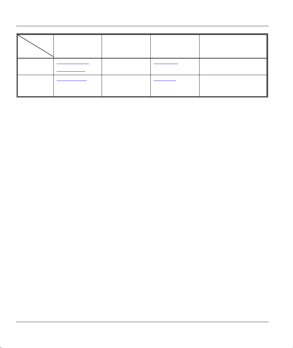
Ad-Hoc (IBSS)
Ad-hoc mode does not require an AP or a wired network. Two or more wireless clients communicate
directly to each other. An ad-hoc network may sometimes be referred to as an Independent Basic Service
Set (IBSS).
Figure 2-1 Ad-hoc Network Example
To set up an ad-hoc network, configure all wireless clients in ad-hoc network type
and use the same SSID and channel.
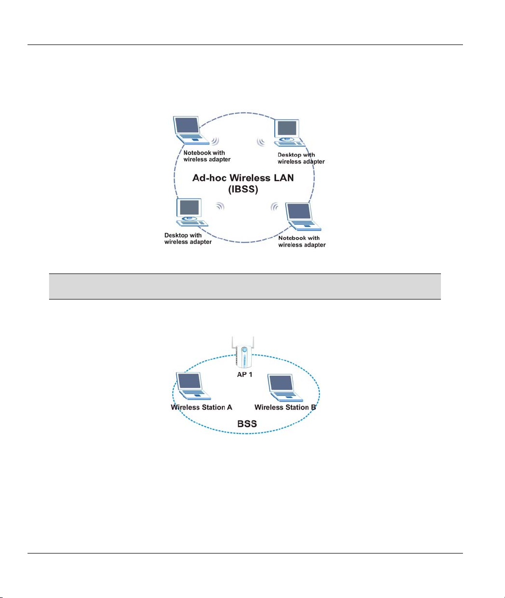
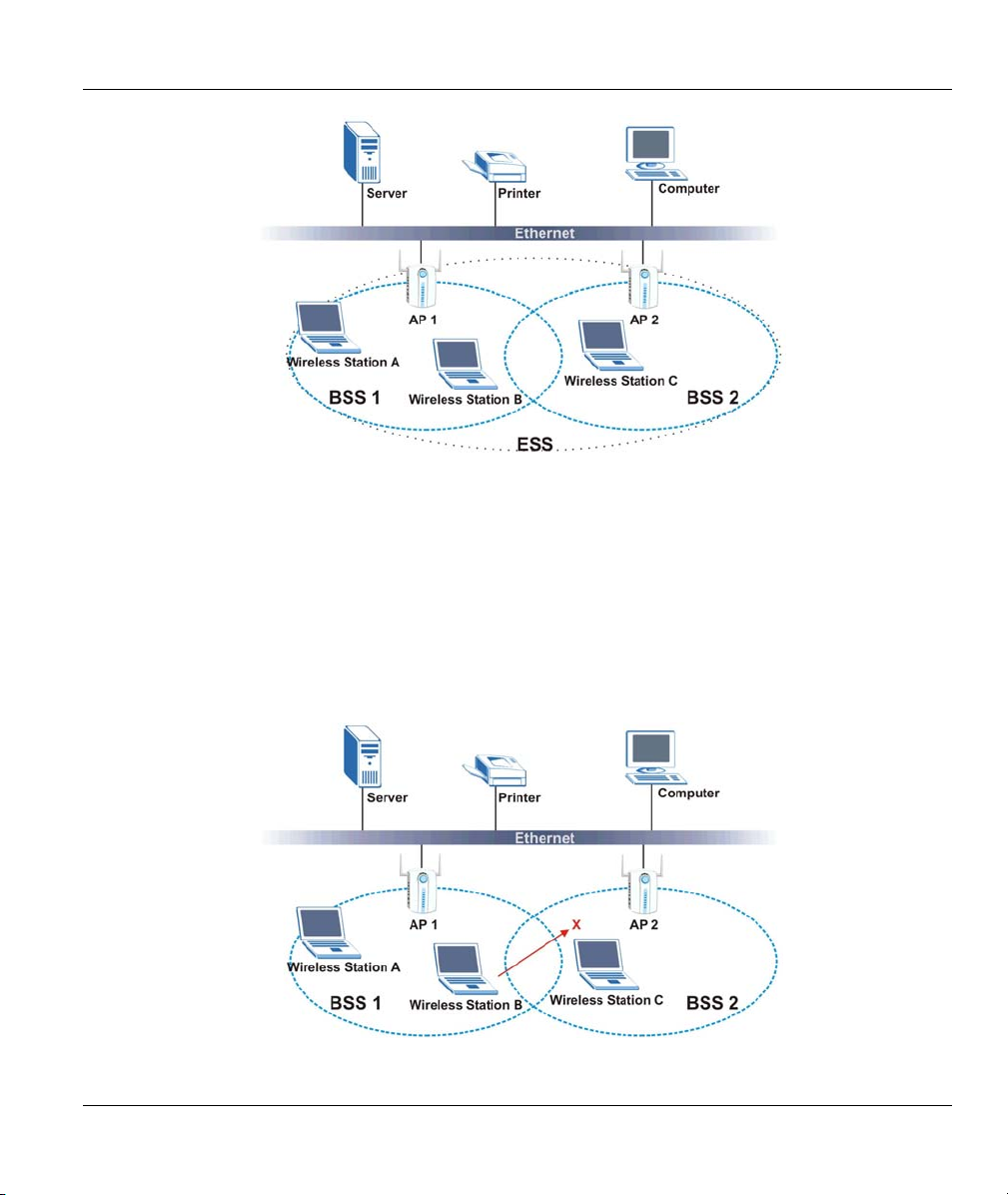
Infrastructure
When a number of wireless clients are connected using a single AP, you have a Basic Service Set (BSS).
Figure 2-2 BSS Example
A series of overlapping BSS and a network medium, such as an Ethernet forms an Extended Service Set
(ESS) or infrastructure network. All communication is done through the AP, which relays data packets to
other wireless clients or devices connected to the wired network. Wireless clients can then access resource,
such as the printer, on the wired network.
2-2 Wireless LAN Network
Page 21
ZyAIR G-405 User’s Guide
Figure 2-3 Infrastructure Network Example
2.1.5 Roaming
In an infrastructure network, wireless stations are able to switch from one BSS to another as they move
between the coverage areas. During this period, the wireless stations maintain uninterrupted connection to
the network. This is roaming. As the wireless station moves from place to place, it is responsible for
choosing the most appropriate AP depending on the signal strength, network utilization or other factors.
The following figure depicts a roaming example. When Wireless Client B moves to position X, the ZyAIR
in Wireless Client B automatically switches the channel to the one used by access point AP 2 in order to
stay connected to the network.
Figure 2-4 Roaming Example
Wireless LAN Network 2-3
Page 22
ZyAIR G-405 User’s Guide
2.1.6 Threshold Controls
Fragmentation Threshold
A fragmentation threshold is the maximum data fragment size (between 256 and 2432 bytes) that can be
sent in the wireless network before the ZyAIR will fragment the packet into smaller data frames.
A large fragmentation threshold is recommended for networks not prone to interference while you should
set a smaller threshold for busy networks or networks that are prone to interference.
If the fragmentation threshold value is smaller than the RTS Threshold value (see previously) you set then
the RTS (Request To Send)/CTS (Clear to Send) handshake will never occur as data frames will be
fragmented before they reach RTS Threshold size.
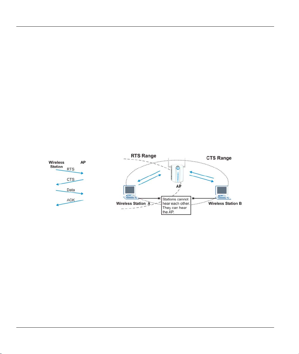
RTS Threshold
A hidden node occurs when two stations are within range of the same access point, but are not within range
of each other. The following figure illustrates a hidden node. Both stations are within range of the access
point (AP) or wireless gateway, but out-of-range of each other, so they cannot “hear” each other, that is
they do not know if the channel is currently being used. Therefore, they are considered hidden from each
other.
Figure 2-5 RTS Threshold
When station A sends data to the AP, it might not know that the station B is already using the channel. If
these two stations send data at the same time, collisions may occur when both sets of data arrive at the AP
at the same time, resulting in a loss of messages for both stations.
RTS Threshold is designed to prevent collisions due to hidden nodes. An RTS Threshold defines the
biggest size data frame you can send before an RTS (Request To Send)/CTS (Clear to Send) handshake is
invoked.
When a data frame exceeds the RTS Threshold value you set (between 0 to 2432 bytes), the station that
wants to transmit this frame must first send an RTS (Request To Send) message to the AP for permission to
send it. The AP then responds with a CTS (Clear to Send) message to all other stations within its range to
notify them to defer their transmission. It also reserves and confirms with the requesting station the time
frame for the requested transmission.
2-4 Wireless LAN Network
Page 23

ZyAIR G-405 User’s Guide
Stations can send frames smaller than the specified RTS Threshold directly to the AP without the RTS
(Request To Send)/CTS (Clear to Send) handshake.
You should only configure RTS Threshold if the possibility of hidden nodes exists on your network and
the “cost” of resending large frames is more than the extra network overhead involved in the RTS (Request
To Send)/CTS (Clear to Send) handshake.
If the RTS Threshold value is greater than the Frag Threshold value, then the RTS (Request To
Send)/CTS (Clear to Send) handshake will never occur as data frames will be fragmented before they reach
RTS Threshold size.
Wireless LAN Network 2-5
Page 24

Page 25
ZyAIR G-405 User’s Guide
Chapter 3
The ZyAIR Wireless Navigator
This chapter introduces and shows you how to use the Navigator to perform basic configuration.
3.1 About the ZyAIR Wireless Navigator
Installing the Navigator on any computer on the network allows you to access and configure the ZyAIR
without connecting the computer directly to the ZyAIR.
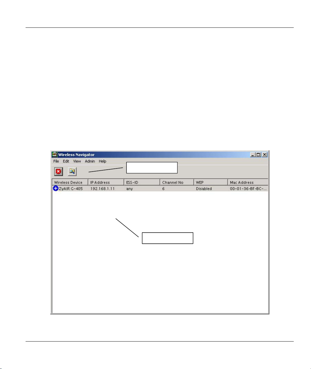
3.2 The Navigator Main Screen
To run the Navigator program, click the icon on the desktop or click Start, Programs, Wireless
Navigator, Wireless Navigator.
Menu Shortcut Bar
Device List Panel
Figure 3-1 Navigator: Main screen
The ZyAIR Wireless Navigator 3-1
Page 26
ZyAIR G-405 User’s Guide
3.3 Device Search
The Navigator automatically searches for the ZyAIR each time. Or click on the menu shortcut bar.
The Navigator displays a list of active ZyAIRs in the device list panel (refer to Figure 3-1).
The following table describes the fields in the device list panel.
Table 3-1 Navigator: Device List Panel
FIELD DESCRIPTION
Wireless Device This field displays the name of the wireless device.
IP Address This field displays the IP address of the wireless device.
ESS-ID This field displays the
Channel No This field displays the channel number the wireless device is using.
WEP
Mac Address This field displays the MAC address of the wireless device.
This field displays whether WEP encryption is activated (Enabled) or not (Disabled).
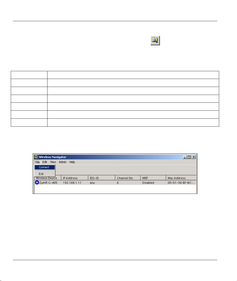
3.4 Connecting to the ZyAIR
Select a ZyAIR in the device list panel and click File, Connect (or double-click on an entry in the device
list panel) to connect to the ZyAIR.
Figure 3-2 Navigator: Connect
Refer to the web configurator chapter for more information.
3.5 Editing the Device List Panel
The following sections show you how to delete and search for the ZyAIRs.
3-2 The ZyAIR Wireless Navigator
Page 27
ZyAIR G-405 User’s Guide
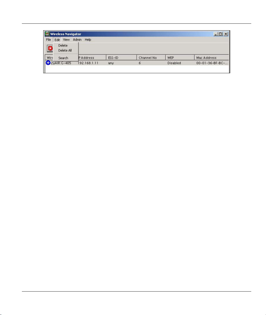
Figure 3-3 Navigator: Edit
3.5.1 Removing Devices
To remove a selected device or all devices from the device list panel, click Edit, Delete or Delete All.
3.5.2 Searching Your ZyAIR
To search for a ZyAIR in your network, click Edit, Search in the Navigator.
3.6 Factory Ethernet Defaults
The Ethernet parameters of the ZyAIR are preset in the factory with the following values:
• IP address of 192.168.1.11
• Subnet mask of 255.255.255.0 (24 bits)
These parameters should work for the majority of installations.
3.6.1 IP Address and Subnet Mask
Similar to the way houses on a street share a common street name, so too do computers on a LAN share
one common network number.
Where you obtain your network number depends on your particular situation. If the ISP or your network
administrator assigns you a block of registered IP addresses, follow their instructions in selecting the IP
addresses and the subnet mask.
If the ISP did not explicitly give you an IP network number, then most likely you have a single user
account and the ISP will assign you a dynamic IP address when the connection is established. The Internet
Assigned Number Authority (IANA) reserved this block of addresses specifically for private use; please do
not use any other number unless you are told otherwise. Let's say you select 192.168.1.0 as the network
number; which covers 254 individual addresses, from 192.168.1.1 to 192.168.1.254 (zero and 255 are
reserved). In other words, the first three numbers specify the network number while the last number
identifies an individual computer on that network.
Once you have decided on the network number, pick an IP address that is easy to remember, for instance,
192.168.1.11, for your ZyAIR, but make sure that no other device on your network is using that IP address.
The subnet mask specifies the network number portion of an IP address.
The ZyAIR Wireless Navigator 3-3
Page 28
ZyAIR G-405 User’s Guide
3.6.2 IP Address Assignment
Every computer on the Internet must have a unique IP address. If your networks are isolated from the
Internet, for instance, only between your two branch offices, you can assign any IP addresses to the hosts
without problems. However, the Internet Assigned Numbers Authority (IANA) has reserved the following
three blocks of IP addresses specifically for private networks.
Table 3-2 Private IP Address Ranges
10.0.0.0 - 10.255.255.255
172.16.0.0 - 172.31.255.255
192.168.0.0 - 192.168.255.255
You can obtain your IP address from the IANA, from an ISP or have it assigned by a private network. If
you belong to a small organization and your Internet access is through an ISP, the ISP can provide you with
the Internet addresses for your local networks. On the other hand, if you are part of a much larger
organization, you should consult your network administrator for the appropriate IP addresses.
Regardless of your particular situation, do not create an arbitrary IP address;
always follow the guidelines above. For more information on address
assignment, please refer to RFC 1597, Address Allocation for Private Internets
and RFC 1466, Guidelines for Management of IP Address Space.
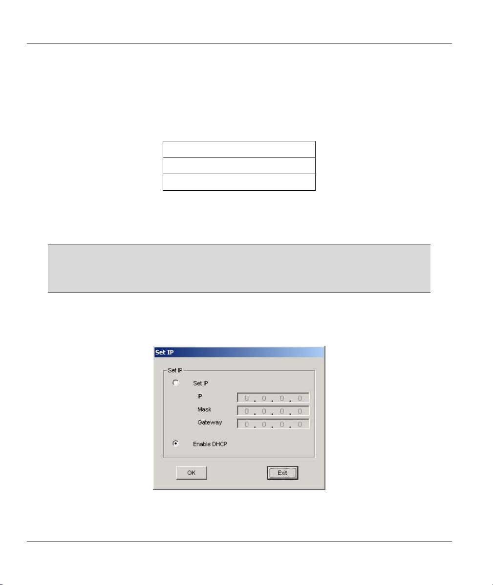
3.6.3 Ethernet Configuration Using the Navigator
To configure the Ethernet settings on the ZyAIR, select a ZyAIR in the Device List Panel and click Admin,
Set IP. A screen displays as shown next.
Figure 3-4 Navigator: Set IP
The following table describes the labels in the screen.
3-4 The ZyAIR Wireless Navigator
Page 29
ZyAIR G-405 User’s Guide
Table 3-3 Navigator: Set IP
LABEL DESCRIPTION
Set IP Select this option to manually configure the Ethernet settings of the ZyAIR.
IP Enter an IP address in dotted decimal notation.
Mask Enter the subnet mask in dotted decimal notation.
Gateway Enter the IP address of the gateway device in dotted decimal notation.
Enable DHCP Select this option to set the ZyAIR to obtain Ethernet information (such as IP address and
subnet mask) from a DHCP server.
OK
Exit
If you change the ZyAIR's IP address, you must use the new IP address if you
Click OK to save the settings.
Click Exit to discard all changes and close this screen.
want to access the web configurator again.
3.7 Firmware Upgrade
Click Admin, FW Upgrade and refer to the related to the web configurator chapter for information.
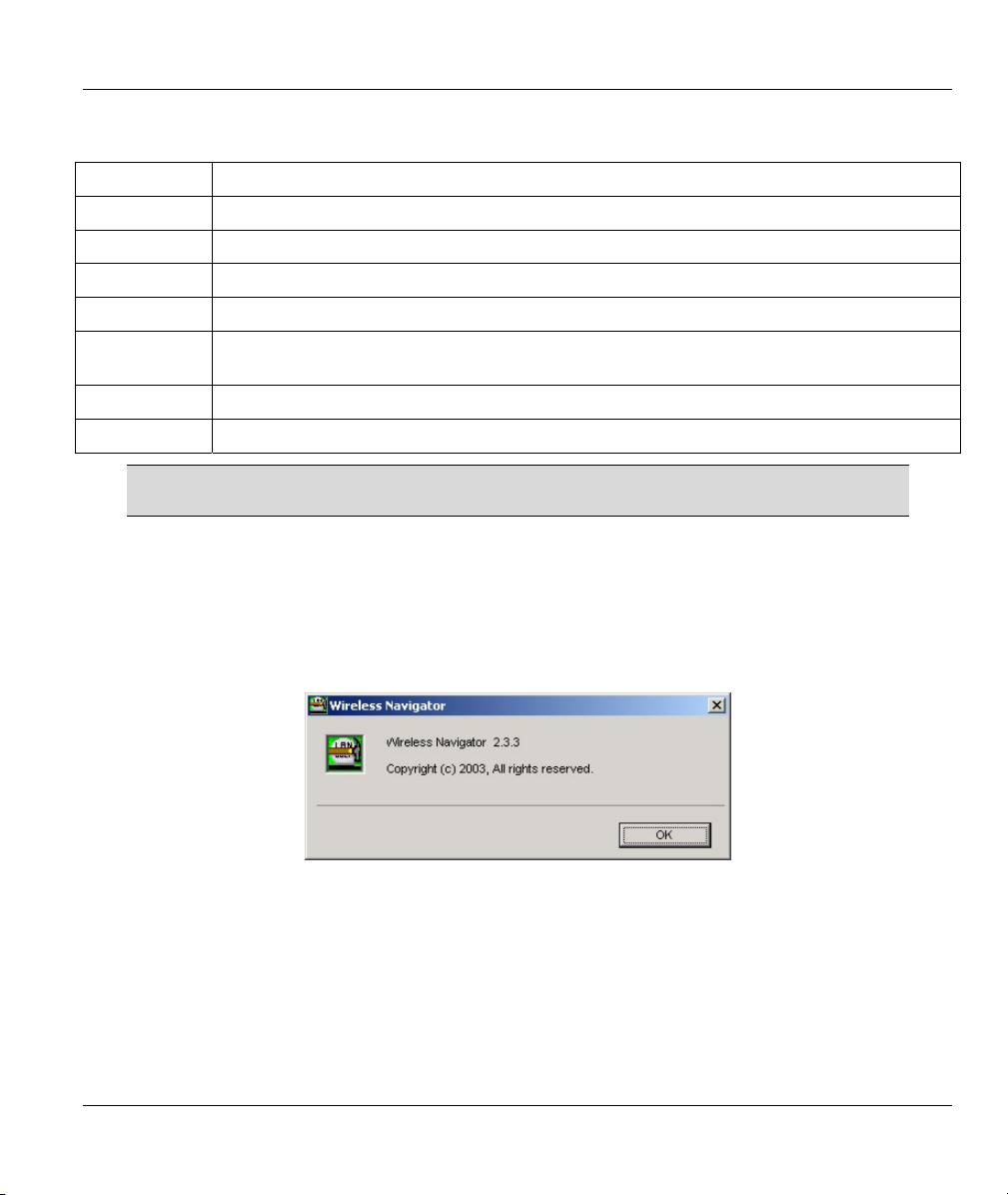
3.8 About the ZyAIR Wireless Navigator
To view the version and copyright information, click Help, About to display the screen as shown.
Figure 3-5 Navigator: About
Click OK to close this screen.
3.9 Uninstalling the ZyAIR Wireless Navigator
Follow the steps below to uninstall the Navigator from your computer.
Step 1. Close and exit the Navigator.
Step 2. Click Start, (all) Programs, Wireless Navigator, Uninstall
The ZyAIR Wireless Navigator 3-5
Page 30
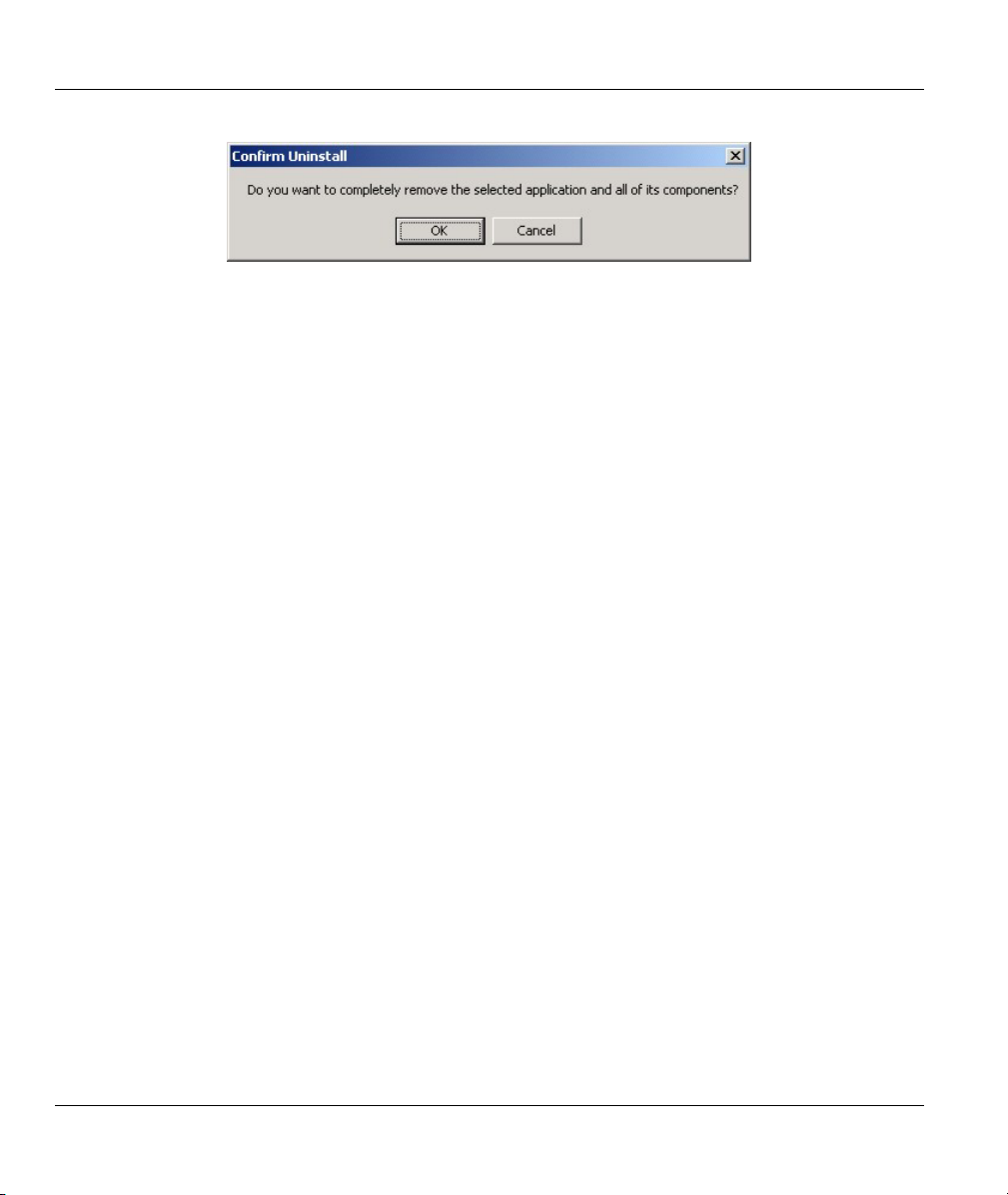
ZyAIR G-405 User’s Guide
Step 3. When prompted, click OK to remove the Navigator.
Figure 3-6 Confirm Uninstallation
Step 4. Click Finish and restart the computer when prompted.
3-6 The ZyAIR Wireless Navigator
Page 31

ZyAIR G-405 User’s Guide
Chapter 4
Introducing the Web Configurator
This chapter shows you how to configure the ZyAIR using the embedded web configurator.
4.1 Web Configurator Overview
The embedded web configurator allows you to manage the ZyAIR from anywhere through a browser such
as Microsoft Internet Explorer or Netscape Navigator. Use Internet Explorer 6.0 and later or Netscape
Navigator 7.0 and later versions with JavaScript enabled. It is recommended that you set your screen
resolution to 1024 by 768 pixels.
You can access the web configurator using the Navigator (see Section 3.4) or directly in a web browser.
4.2 Accessing the ZyAIR Web Configurator
Follow the steps below to access the web configurator using a web browser.
Step 1. Make sure your ZyAIR is properly connected and prepare your computer/ network to connect to
the ZyAIR.
Step 2. Launch your web browser.
Step 3. Type "192.168.1.11" (default) as the URL and press [ENTER]. A login screen displays as
shown.
Figure 4-1 Web Configurator: Login Screen
Step 4. Type “admin” (default) as the password and "1234" (default) as the password and click OK.
Step 5. You should see the Information screen.
Introducing the Web Configurator 4-1
Page 32

ZyAIR G-405 User’s Guide
4.3 Resetting the ZyAIR
If you forget your password or cannot access the ZyAIR, you will need to reset ZyAIR to the factory
defaults. This means that you will lose all configurations that you had previously and the speed of the
console port will be reset to the default of 9600bps with 8 data bit, no parity, one stop bit and flow control
set to none. The use name will be reset to “admin” and the password to “1234”.
4.3.1 Method of Restoring Factory-Defaults
You can erase the current configuration and restore factory defaults in three ways:
• Use the RESET button on the ZyAIR to reset to the factory defaults. Use this method for cases
when the password or IP address of the ZyAIR is not known.
• Use the web configurator to restore defaults.
4.3.2 Procedure to Use the RESET Button
Make sure the PWR LED is not blinking.
Step 1. Press the RESET button for about 10 seconds, then release it and press the button in once.
Step 2. If the PWR LED begins to blink, the defaults have been restored and the ZyAIR restarts.
Wait for the ZyAIR to finish restarting before accessing it again.
4.4 Navigating the ZyAIR Web Configurator
The following summarizes how to navigate the web configurator from the Information screen.
4-2 Introducing the Web Configurator
Page 33

ZyAIR G-405 User’s Guide
Navigation Panel. Click
on a tab to display the
related screen.
Figure 4-2 Web Configurator: Information
4.5 Change Your Password
After you log in for the first time, it is recommended you change the default administrator password. Click
Admin in the navigation panel and scroll down to the Password and Reset section as shown in the screen
next.
Introducing the Web Configurator 4-3
Page 34

ZyAIR G-405 User’s Guide
Figure 4-3 Web Configurator: Change Administrator Login Password
4.6 The Information Screen
The Information screen displays every time you access the web configurator. This screen shows the
current configuration of your ZyAIR. Click the Info tab to display the screen as shown next.
4-4 Introducing the Web Configurator
Page 35

ZyAIR G-405 User’s Guide
Figure 4-4 Web Configurator: Information
The following table describes the labels in this screen.
Table 4-1 Web Configurator: Information
LABEL DESCRIPTION
Link Information
Current SSID This field displays the name of the wireless device to which the ZyAIR is associated.
Transmission
Signal Strength The percentage number indicates the strength of the radio signal.
This field displays the current transmission rate of the ZyAIR.
Rate
Introducing the Web Configurator 4-5
Page 36

ZyAIR G-405 User’s Guide
Table 4-1 Web Configurator: Information
LABEL DESCRIPTION
BSSID This field displays the MAC address (in hexadecimal notation) of the Ethernet device
connected to the LAN port.
WEP
Adapter Information
Adapter Name This field displays the model name of your ZyAIR. Select from the drop-down list menu if
IP Address This field displays the IP address of the ZyAIR.
Subnet Mask This field displays the subnet mask.
Gateway This field displays IP address of the gateway device.
Adapter
Firmware
Version
Site Survey The site survey function allows you to scan for available wireless access points
Scan
This field indicates whether WEP data encryption is activated (Enable) or not (Disable).
you have more than one wireless LAN adapter in your computer.
This field displays the firmware version number.
automatically.
Click Scan to search for available access points.
4.6.1 Using the Site Survey
To scan for available wireless access points in your network, click Scan in the Information screen. Wait
for the scan process to complete. An Available Access Points screen displays showing the scan results.
4-6 Introducing the Web Configurator
Page 37

ZyAIR G-405 User’s Guide
Figure 4-5 Web Configurator: Information: Site Survey
The following table describes the labels in this screen.
Table 4-2 Web Configurator: Information: Site Survey
LABEL DESCRIPTION
SSID This field displays the SSID (or name) of each wireless device.
BSSID This field displays the MAC address of the wireless device.
Channel This field displays the channel number used by each wireless device.
Strength This field displays the signal strength of each wireless device in percentage.
Mode
Refresh
This field displays the wireless standard (802.11b or 802.11g) and network type (Infra or Ad
Hoc) of the wireless device and indicates whether WEP data encryption is activated (WEP).
Click Refresh to scan for available wireless device(s) within transmission range.
Introducing the Web Configurator 4-7
Page 38

Page 39

ZyAIR G-405 User’s Guide
Chapter 5
Basic Wireless LAN Setup
This chapter shows you how to configure the Setup screen.
5.1 Overview
The Setup screen allows you to configure basic wireless LAN and MAC address cloning settings.
Click the Setup tab in the navigation panel to display the screen as shown.
5.1.1 Basic Wireless LAN Configuration
To configure basic wireless LAN settings, click Setup in the navigation panel to display the screen as
shown.
Basic Wireless LAN Setup 5-1
Page 40

ZyAIR G-405 User’s Guide
Figure 5-1 Web Configurator: Setup: Basic Wireless
5-2 Basic Wireless LAN Setup
Page 41

ZyAIR G-405 User’s Guide
The following table describes the related labels in this screen.
Table 5-1 Web Configurator: Setup: Basic Wireless
LABEL DESCRIPTION
Basic Wireless
Wireless Mode
Wireless
Network Name
(SSID)
Channel
Transmission
Rate (Mbps)
802.11 Mode
OK
Cancel
Select Infrastructure or Ad-Hoc from the drop-down list box.
Select Infrastructure to associate to an AP.
Select Ad-Hoc to associate to a peer computer.
Enter the SSID (Service Set ID) of the wireless network to which you want to associate.
To associate to an ad-hoc network, you must enter the same SSID as the peer
computer.
Enter Any to associate to or roam between any infrastructure wireless networks. This is
the default setting.
This field is applicable when you select Ad-Hoc in the Wireless Mode field.
Select the channel number from the drop-down list box. To associate to an ad-hoc
network, you must use the same channel as the peer computer.
Select a transmission speed from the drop-down list box. Choose from Auto (default),
1Mbps, 2Mbps, 5.5Mbps, 6Mbps, 9Mbps, 11Mbps, 12Mbps, 18Mbps, 24Mbps,
36Mbps, 48Mbps and 54Mbps.
Select Mix Mode to set the ZyAIR to operate in a wireless network with both
IEEE802.11b and IEEE802.11g wireless devices.
Select 802.11g Only to set the ZyAIR to operate in a wireless network with only
IEEE802.11g wireless devices. If you select this, the ZyAIR may not communicate with
IEEE802.11b wireless devices.
Click OK to save the changes.
Click Cancel to discard all the changes.
5.1.2 LAN MAC Address Cloning
Every Ethernet device has a unique MAC (Media Access Control) address. The MAC address is assigned at
the factory and consists of six pairs of hexadecimal characters, for example, 00:A0:C5:00:00:02.
You can configure the LAN port's MAC address by either using the factory default or cloning the MAC
address from a computer on your LAN.
To set the LAN MAC address, click Setup in the navigation panel and scroll down to the bottom of the
screen.
Basic Wireless LAN Setup 5-3
Page 42

ZyAIR G-405 User’s Guide
Figure 5-2 Web Configurator: Setup: MAC Clone
5-4 Basic Wireless LAN Setup
Page 43

ZyAIR G-405 User’s Guide
The following table describes the related labels in this screen.
Table 5-2 Web Configurator: Setup: MAC Clone
LABEL DESCRIPTION
MAC Clone
Cloning Mode
Manual Select this option to manually enter the MAC address.
Enter MAC
Address
OK
Cancel
Select Enable to activate MAC address clone. Otherwise, select Disable.
Auto Select this option to set the ZyAIR to automatically clone or copy the MAC address of the
Ethernet device connected to the LAN port.
This field is applicable when you select Manual.
Enter the MAC address of the Ethernet device on the LAN whose MAC you are cloning
Click OK to save the changes.
Click Cancel to discard all the changes.
Basic Wireless LAN Setup 5-5
Page 44

Page 45

ZyAIR G-405 User’s Guide
Chapter 6
Wireless LAN Security Setup
This chapter shows you how to configure wireless LAN security using the Security screen.
6.1 About Wireless LAN Security
Wireless LAN security is vital to your network to protect wireless communication between wireless clients
and the wired network.
The figure below shows the possible wireless security levels on your ZyAIR. EAP (Extensible
Authentication Protocol) is used for authentication and utilizes dynamic WEP key exchange. It requires
interaction with a RADIUS (Remote Authentication Dial-In User Service) server either on the WAN or
your LAN to provide authentication service for wireless stations.
Figure 6-1 Wireless LAN Security Levels
Configure the wireless LAN security using the Security screen. If you do not enable any wireless security
on your ZyAIR, communication between the ZyAIR and the wired network is accessible to any wireless
networking device that is in the coverage area.
Make sure the security settings are the same on the ZyAIR and the intermediary
AP and/or your network security server device.
Wireless LAN Security Setup 6-1
Page 46

ZyAIR G-405 User’s Guide
6.1.1 Data Encryption with WEP
WEP (Wired Equivalent Privacy) encryption scrambles all data packets transmitted between the ZyAIR and
the AP or other wireless stations to keep network communications private. Both the wireless clients and the
access points must use the same WEP key for data encryption and decryption.
There are two ways to create WEP keys in your ZyAIR.
• Automatic WEP key generation based on a “password phrase” called a passphrase. The passphrase
is case sensitive. You must use the same passphrase for all WLAN adapters with this feature in the
same WLAN.
For WLAN adapters without the passphrase feature, you can still take advantage of this feature by
writing down the four automatically generated WEP keys from the Security screen of the ZyAIR
Navigator and entering them manually as the WEP keys in the other WLAN adapter(s).
• Enter the WEP keys manually.
Your ZyAIR allows you to configure up to four 64-bit or 128-bit WEP keys but only one key can be
enabled at any one time.
6.1.2 IEEE 802.1x
The IEEE 802.1x standard outlines enhanced security methods for both the authentication of wireless
stations and encryption key management. Authentication can be done using an external RADIUS server.
EAP Authentication
EAP (Extensible Authentication Protocol) is an authentication protocol that runs on top of the IEEE802.1x
transport mechanism in order to support multiple types of user authentication. By using EAP to interact
with an EAP-compatible RADIUS server, an access point helps a wireless station and a RADIUS server
perform authentication.
The type of authentication you use depends on the RADIUS server and an intermediary AP(s) that supports
IEEE802.1x. The ZyAIR supports EAP-TLS, EAP-TTLS and EAP-MD5. Refer to the Types of EAP
Authentication appendix for descriptions.
For EAP-TLS and EAP-TTLS authentication types, you must first have a wired connection to the network
and obtain the certificate(s) from a certificate authority (CA). A certificate (also called digital IDs) can be
used to authenticate users and a CA issues certificates and guarantees the identity of each certificate owner.
Dynamic WEP Key Exchange
An AP maps a unique key that is generated with the RADIUS server. This key expires when the wireless
connection times out, disconnects or reauthentication times out. A new WEP key is generated each time
reauthentication is performed.
If this feature is enabled, it is not necessary to configure a default WEP encryption key in the Security
configuration screen. You may still configure and store keys here, but they will not be used while Dynamic
WEP is enabled.
6-2 Wireless LAN Security Setup
Page 47

ZyAIR G-405 User’s Guide
To use Dynamic WEP, enable and configure the RADIUS server and enable dynamic WEP key exchange
in the Security configuration screen. Ensure that the ZyAIR’s EAP type is configured to either TLS or
TTLS.
The MD5 EAP type does not support dynamic WEP key exchange. You must configure the WEP keys for
data encryption.
6.1.3 WPA
Wi-Fi Protected Access (WPA) is a subset of the IEEE 802.11i security specification draft. Key differences
between WPA and WEP are user authentication and improved data encryption.
User Authentication
WPA applies IEEE 802.1x and Extensible Authentication Protocol (EAP) to authenticate wireless clients
using an external RADIUS database.
Therefore, if you don’t have an external RADIUS server you should use WPA-PSK (WPA -Pre-Shared
Key) that only requires a single (identical) password entered into each access point, wireless gateway and
wireless client. As long as the passwords match, a client will be granted access to a WLAN.
Encryption
WPA improves data encryption by using Temporal Key Integrity Protocol (TKIP), Message Integrity
Check (MIC) and IEEE 802.1x.
Temporal Key Integrity Protocol (TKIP) uses 128-bit keys that are dynamically generated and distributed
by the authentication server. It includes a per-packet key mixing function, a Message Integrity Check
(MIC) named Michael, an extended initialization vector (IV) with sequencing rules, and a re-keying
mechanism.
TKIP regularly changes and rotates the encryption keys so that the same encryption key is never used
twice. The RADIUS server distributes a Pairwise Master Key (PMK) key to the AP that then sets up a key
hierarchy and management system, using the pair-wise key to dynamically generate unique data encryption
keys to encrypt every data packet that is wirelessly communicated between the AP and the wireless clients.
This all happens in the background automatically.
The Message Integrity Check (MIC) is designed to prevent an attacker from capturing data packets, altering
them and resending them. The MIC provides a strong mathematical function in which the receiver and the
transmitter each compute and then compare the MIC. If they do not match, it is assumed that the data has
been tampered with and the packet is dropped.
By generating unique data encryption keys for every data packet and by creating an integrity checking
mechanism (MIC), TKIP makes it much more difficult to decode data on a Wi-Fi network than WEP,
making it difficult for an intruder to break into the network.
The encryption mechanisms used for WPA and WPA-PSK are the same. The only difference between the
two is that WPA-PSK uses a simple common password, instead of user-specific credentials. The commonpassword approach makes WPA-PSK susceptible to brute-force password-guessing attacks but it’s still an
improvement over WEP as it employs an easier-to-use, consistent, single, alphanumeric password.
Wireless LAN Security Setup 6-3
Page 48

ZyAIR G-405 User’s Guide
6.1.4 WPA-PSK Application Example
A WPA-PSK application looks as follows.
Step 1. First enter identical passwords into the AP and all wireless clients. The Pre-Shared Key (PSK)
must consist of between 8 and 63 ASCII characters (including spaces and symbols).
Step 2. The AP checks each client’s password and (only) allows it to join the network if it matches its
password.
Step 3. The AP derives and distributes keys to the wireless clients.
Step 4. The AP and wireless clients use the TKIP encryption process to encrypt data exchanged
between them.
Figure 6-2
WPA - PSK Authentication
6.1.5 WPA with RADIUS Application Example
You need the IP address of the RADIUS server, its port number (default is 1812), and the RADIUS shared
secret. A WPA application example with an external RADIUS server looks as follows. “A” is the RADIUS
server. “DS” is the distribution system.
Step 1. The AP passes the wireless client’s authentication request to the RADIUS server.
Step 2. The RADIUS server then checks the user's identification against its database and grants or
denies network access accordingly.
Step 3. The RADIUS server distributes a Pairwise Master Key (PMK) key to the AP that then sets up a
key hierarchy and management system, using the pair-wise key to dynamically generate unique
6-4 Wireless LAN Security Setup
Page 49

ZyAIR G-405 User’s Guide
data encryption keys to encrypt every data packet that is wirelessly communicated between the
AP and the wireless clients.
Figure 6-3 WPA with RADIUS Application Example
6.2 Activate/Deactivate Wireless LAN Security
Refer to Section 6.1 for more information on WEP data encryption.
To activate or deactivate WLAN security, click the Security tab in the navigation panel to display the
screen as shown next.
Wireless LAN Security Setup 6-5
Page 50

ZyAIR G-405 User’s Guide
Figure 6-4 Web Configurator: Security
The following table describes the labels in this screen.
Table 6-1 Web Configurator: Security
LABEL DESCRIPTION
Enable Security
Security
OK
Cancel
Select Enable to activate WEP data encryption. Otherwise select Disable to deactivate
it.
Click Edit Security Settings to set the security settings. A configuration screen displays
as shown. A configuration screen displays.
Click OK to save the changes.
Click Cancel to discard all the changes.
6.3 Configuring WEP Encryption Keys
The WEP keys are used to encrypt communication before it is transmitted. The values for the keys must be
set up exactly the same on the APs or other peer ad-hoc wireless computers as they are on the ZyAIR.
To set up WEP encryption keys, click Edit Security Settings in the Security screen (see Figure 6-4). The
Security configuration screen varies depending on what you select in the Security Mode field.
6-6 Wireless LAN Security Setup
Page 51

ZyAIR G-405 User’s Guide
Figure 6-5 Security: Set Security Settings: WEP
The following table describes the labels in this screen.
Table 6-2 Security: Set Security Settings: WEP
LABEL DESCRIPTION
Security Mode
Default Transmit Key Select one of the WEP keys to use for data encryption/decryption.
WEP Encryption
Passphrase To automatically generate the WEP keys based on a pass phrase, enter the pass
Select WEP from the drop-down list box to use WEP key encryption.
Make sure the ZyAIR uses the same WEP key as the access point/wireless
station(s).
Select either 64bit-WEP or 128bit-WEP from the drop-down list box and set the
related fields.
phrase in the field provided and click Generate. The ZyAIR automatically generates
four different WEP keys and displays them in the key fields below. Write down the
automatically generated WEP keys in and use them to manually set the WEP keys
in other WLAN adapters.
The passphrase is case-sensitive. You must use the same passphrase for all
wireless LAN adapters with this feature in the same WLAN.
Wireless LAN Security Setup 6-7
Page 52

ZyAIR G-405 User’s Guide
Table 6-2 Security: Set Security Settings: WEP
LABEL DESCRIPTION
Key 1 … 4 Enter the WEP keys in the fields provided.
If you select 64bit in the WEP Encryption field, enter 10 hexadecimal digits in the
range of “A-F”, “a-f” and “0-9” (e.g. 11AA22BB33).
If you select 128bit in the WEP Encryption field, enter 26 hexadecimal digits in the
range of “A-F”, “a-f” and “0-9” (for example, 00112233445566778899AABBCC).
The values for the WEP keys must be set up exactly the same
on all wireless devices in the same wireless LAN.
ASCII WEP key is case sensitive.
Apply
Click Apply to save the changes.
6.4 Configuring IEEE802.1x
The following sections describe how to configure IEEE802.1x security with various authentication
methods.
To set the IEEE802.1x WLAN security, select 802.1x in the Security Mode field in the Security
configuration screen.
6.4.1 IEEE802.1x with MD5
Follow the steps below to configure IEEE802.1x security with MD5EAP authentication type.
Step 1. Select 802.1x in the Security Mode field in the Security configuration screen.
Step 2. Select MD5 in the EAP Type field. A screen displays as shown.
6-8 Wireless LAN Security Setup
Page 53

ZyAIR G-405 User’s Guide
Figure 6-6 Security: Set Security Settings: IEEE802.1x: MD5
The following table describes the related labels in this screen.
Table 6-3 Security: Set Security Settings: IEEE802.1x: MD5
LABEL DESCRIPTION
Security Mode
EAP Type
Cipher Type This read-only field shows whether dynamic WEP key exchange is activated.
WEP Encryption Refer to Table 6-2 for WEP encryption related field descriptions.
Select 802.1x from the drop-down list box.
Select MD5 as the EAP type.
When you select MD5 in the EAP Type field, this field displays None.
When you select TLS or TTLS in the EAP Type field, this field displays Dynamic WEP.
Wireless LAN Security Setup 6-9
Page 54

ZyAIR G-405 User’s Guide
Table 6-3 Security: Set Security Settings: IEEE802.1x: MD5
LABEL DESCRIPTION
User ID Enter a user name of your network account provided by a network administrator.
Password Enter the password associated with the user name above.
Apply
Re-Authenticate
View Log
Click Apply to save the changes.
Click Re-Authenticate to gain access to the wireless/wired network.
Click View Log to see the log screen.
6.4.2 IEEE802.1x with TLS
You must first have a wired connection to a network and obtain the certificate(s)
from a certificate authority (CA). Consult your network administrator for more
information.
Follow the steps below to configure IEEE802.1x security with TLS EAP authentication type.
Step 1. Select 802.1x in the Security Mode field in the Security configuration screen.
Step 2. Select TLS in the EAP Type field. A screen displays as shown.
6-10 Wireless LAN Security Setup
Page 55

ZyAIR G-405 User’s Guide
Figure 6-7 Security: Set Security Settings: IEEE802.1x: TLS
The following table describes the related labels in this screen.
Table 6-4 Security: Set Security Settings: IEEE802.1x: TLS
LABEL DESCRIPTION
Security Mode
EAP Type
Cipher Type This read-only field shows whether dynamic WEP key exchange is activated.
User ID Enter a user name.
User
Certificate
Select 802.1x from the drop-down list box.
Select TLS as the EAP type.
When you select MD5 in the EAP Type field, this field displays None.
When you select TLS or TTLS in the EAP Type field, this field displays Dynamic WEP.
This is the user name that you or an administrator set up on the RADIUS server.
Specify the location and name of the user certificate or click Browse to locate it. Click
Upload to import the certificate.
Wireless LAN Security Setup 6-11
Page 56

ZyAIR G-405 User’s Guide
Table 6-4 Security: Set Security Settings: IEEE802.1x: TLS
LABEL DESCRIPTION
Root
Certificate
Apply
ReAuthenticate
View Log
Specify the location and name of the root certificate or click Browse to locate it. Click
Upload to import the certificate.
Click Apply to save the changes.
Click Re-Authenticate to gain access to the wireless/wired network.
Click View Log to see the log screen.
6.4.3 IEEE802.1x with TTLS
You must first have a wired connection to a network and obtain the certificate(s)
from a certificate authority (CA). Consult your network administrator for more
information.
Follow the steps below to configure IEEE802.1x security with TTLS EAP authentication type.
Step 1. Select 802.1x in the Security Mode field in the Security configuration screen.
Step 2. Select TLS in the EAP Type field. A screen displays as shown.
6-12 Wireless LAN Security Setup
Page 57

ZyAIR G-405 User’s Guide
Figure 6-8 Security: Set Security Settings: IEEE802.1x: TTLS
The following table describes the related labels in this screen.
Table 6-5 Security: Set Security Settings: IEEE802.1x: TTLS
LABEL DESCRIPTION
Security
Mode
EAP Type
Cipher Type This read-only field shows whether dynamic WEP key exchange is activated.
User ID Enter a user name.
Password Enter the password associated with the user name above.
Root
Certificate
Select 802.1x from the drop-down list box.
Select TTLS as the EAP type.
When you select MD5 in the EAP Type field, this field displays None.
When you select TLS or TTLS in the EAP Type field, this field displays Dynamic WEP.
This is the user name that you or an administrator set up on the RADIUS server.
Specify the location and name of the root certificate or click Browse to locate it. Click
Upload to import the certificate.
Wireless LAN Security Setup 6-13
Page 58

ZyAIR G-405 User’s Guide
Table 6-5 Security: Set Security Settings: IEEE802.1x: TTLS
LABEL DESCRIPTION
Apply
ReAuthenticate
View Log
Click Apply to save the changes.
Click Re-Authenticate to gain access to the wireless/wired network.
Click View Log to see the log screen.
6.5 Configuring WPA
The following sections describe how to configure WPA security with various authentication methods.
To set the IEEE802.1x WLAN security, select WPA in the Security Mode field in the Security
configuration screen.
6.5.1 WPA with TLS
You must first have a wired connection to a network and obtain the certificate(s)
from a certificate authority (CA). Consult your network administrator for more
information.
Follow the steps below to configure WPA security with TLS EAP authentication type.
Step 1. Select WPA in the Security Mode field in the Security configuration screen.
Step 2. Select TLS in the EAP Type field. A screen displays as shown.
6-14 Wireless LAN Security Setup
Page 59

ZyAIR G-405 User’s Guide
Figure 6-9 Security: Set Security Settings: WPA: TLS
The following table describes the labels in this screen.
Table 6-6 Security: Set Security Settings: WPA: TLS
LABEL DESCRIPTION
Security
Mode
EAP Type
WPA
Algorithm
User ID Enter a user name.
User
Certificate
Select WPA-PSK from the drop-down list box.
Select TTLS as the EAP type.
WPA and WPA-PSK use the same Temporal Key Integrity Protocol (TKIP) authentication
algorithm. Refer to the User Authentication section for more information.
This is the user name that you or an administrator set up on the RADIUS server.
Specify the location and name of the user certificate or click Browse to locate it. Click
Upload to import the certificate.
Wireless LAN Security Setup 6-15
Page 60

ZyAIR G-405 User’s Guide
Table 6-6 Security: Set Security Settings: WPA: TLS
LABEL DESCRIPTION
Root
Certificate
Apply
ReAuthenticate
View Log
Specify the location and name of the root certificate or click Browse to locate it. Click
Upload to import the certificate.
Click Apply to save the changes.
Click Re-Authenticate to gain access to the wireless/wired network.
Click View Log to see the log screen.
6.5.2 WPA with TTLS
You must first connect to the wired network using an Ethernet cable and obtain
the certificate(s) from a certificate authority (CA). Consult your network
administrator for more information.
Follow the steps below to configure WPA security with TTLS EAP authentication type.
Step 1. Select WPA in the Security Mode field in the Security configuration screen.
Step 2. Select TTLS in the EAP Type field. A screen displays as shown.
6-16 Wireless LAN Security Setup
Page 61

ZyAIR G-405 User’s Guide
Figure 6-10 Security: Set Security Settings: WPA: TTLS
The following table describes the labels in this screen.
Table 6-7 Security: Set Security Settings: WPA: TTLS
LABEL DESCRIPTION
Security
Mode
EAP Type
WPA
Algorithm
User ID Enter a user name.
Password Enter the password associated with the user name above.
Root
Certificate
Apply
Select WPA-PSK from the drop-down list box.
Select TTLS as the EAP type.
WPA and WPA-PSK use the same Temporal Key Integrity Protocol (TKIP) authentication
algorithm. Refer to the User Authentication section for more information.
This is the user name that you or an administrator set up on the RADIUS server.
Specify the location and name of the root certificate or click Browse to locate it. Click
Upload to import the certificate.
Click Apply to save the changes.
Wireless LAN Security Setup 6-17
Page 62

ZyAIR G-405 User’s Guide
Table 6-7 Security: Set Security Settings: WPA: TTLS
LABEL DESCRIPTION
ReAuthenticate
View Log
Click Re-Authenticate to gain access to the wireless/wired network.
Click View Log to see the log screen.
6.5.3 WPA-PSK
Follow the steps below to configure WPA-PSK security on the ZyAIR.
Select WPA-PSK in the Security Mode field in the Security configuration screen. A screen displays as
shown.
Figure 6-11 Security: Set Security Settings: WPA-PSK
The following table describes the labels in this screen.
Table 6-8 Security: Set Security Settings: WPA-PSK
LABEL DESCRIPTION
Security
Mode
WPA
Algorithm
Select WPA-PSK from the drop-down list box.
This field displays the algorithm type used.
6-18 Wireless LAN Security Setup
Page 63

ZyAIR G-405 User’s Guide
Table 6-8 Security: Set Security Settings: WPA-PSK
LABEL DESCRIPTION
WPA Pre
Shared Key
Apply
ReAuthenticate
View Log
The encryption mechanisms used for WPA and WPA-PSK are the same. The only
difference between the two is that WPA-PSK uses a simple common password, instead of
user-specific credentials.
Type a pre-shared key from 8 to 63 case-sensitive ASCII characters (including spaces and
symbols).
Click Apply to save the changes.
Click Re-Authenticate to gain access to the wireless/wired network.
Click View Log to see the log screen.
6.6 The Log Table Screen
The Log Table screen displays the system logs. This log screen is only available when you select 802.1x,
WPA or WPA-PSK in the Security Mode field in the Security configuration screen.
To view the logs, click View Log in the Security configuration screen.
Figure 6-12 Security: Set Security Settings: Log Table
The following table describes the labels in this screen.
Table 6-9 Security: Set Security Settings: WPA-PSK
LABEL DESCRIPTION
Refresh
No. This field displays the log entry index number.
Log
Message
Close
Click Refresh to update this screen.
This field displays a brief description of the log.
Click Close to close this screen.
Wireless LAN Security Setup 6-19
Page 64

Page 65

ZyAIR G-405 User’s Guide
Chapter 7
System Management and Maintenance
This chapter shows you how to perform basic system settings and firmware upgrade using the
Administration screen.
7.1 Introduction
The Administration screen allows you to configure general system settings (such as the device name and
the login password) and the LAN port settings and perform firmware upgrade.
Click the Admin tab in the navigation panel to display the Administration screen as shown next.
System Management and Maintenance 7-1
Page 66

ZyAIR G-405 User’s Guide
Figure 7-1 Web Configurator: Administration
Refer to the following sections to configure this screen.
7-2 System Management and Maintenance
Page 67

ZyAIR G-405 User’s Guide
7.2 Configuring the Device Name
The device name is used for identification purposes only. To set the device name, enter a descriptive name
in the Device Name field in the Administration screen. Then click Save.
Figure 7-2 Web Configurator: Administration: Adapter Name
7.3 IP Settings
Refer to Section 3.6 for background information and LAN port default settings.
To configure the LAN port on the ZyAIR, set the related fields in the Administration screen.
Figure 7-3 Web Configurator: Administration: IP Settings
The following table describes the related labels in this screen.
Table 7-1 Web Configurator: Administration: IP Settings
LABEL DESCRIPTION
IP Settings
System Management and Maintenance 7-3
Page 68

ZyAIR G-405 User’s Guide
Table 7-1 Web Configurator: Administration: IP Settings
LABEL DESCRIPTION
IP Address
Mode
Mask Enter the subnet mask in dotted decimal notation.
Gateway Enter the IP address of the gateway device in dotted decimal notation.
OK
Cancel
Select DHCP to set the ZyAIR to obtain Ethernet information (such as IP address and subnet
mask) from a DHCP server.
Select Static to manually configure the ZyAIR to use a static (fixed) IP address. Then set the
following fields.
IP Enter an IP address in dotted decimal notation.
Click OK to save the settings.
Click Cancel to discard all changes.
If you change the ZyAIR's IP address, you must use the new IP address if you
want to access the web configurator again.
7.4 Changing the Administrator Login Password
Set the related fields in the Administration screen to change the administrator login password.
Figure 7-4 Web Configurator: Administration: Password
Table 7-2 Web Configurator: Administration: Password
LABEL DESCRIPTION
Password Enter a password in the fields provided.
Save
Click Save to save the settings.
7-4 System Management and Maintenance
Page 69

ZyAIR G-405 User’s Guide
Table 7-2 Web Configurator: Administration: Password
LABEL DESCRIPTION
Cancel
Click Cancel to discard all changes.
7.5 Restore Configuration
Use the Administration screen to reset the ZyAIR back to the factory default configuration.
All your custom configuration will be erased.
Follow the steps below to reset your ZyAIR.
Step 1. In the Administration screen and scroll down to Password and Reset.
Figure 7-5 Web Configurator: Administration: Reset to Factory Defaults
Step 2. Select Yes and click Save. A warning screen displays as shown.
Figure 7-6 Reset to Factory Defaults: Confirm Screen
Step 3. Click OK to confirm. The ZyAIR restarts automatically. Wait for the ZyAIR to finish rebooting
before accessing the ZyAIR again.
System Management and Maintenance 7-5
Page 70

ZyAIR G-405 User’s Guide
7.6 Firmware Upgrade
Make sure you have downloaded (and upzipped) the correct and latest firmware file for your ZyAIR model
before uploading to the ZyAIR.
Make sure you upload the correct model firmware as uploading the wrong model
firmware may damage your ZyAIR.
WARNING!
Do not interrupt the file transfer process as this may PERMANENTLY DAMAGE
YOUR ZyAIR. When the firmware upgrade process is complete, the ZyAIR will
automatically restart.
Follow the steps below to upgrade the firmware on the ZyAIR.
Step 1. In the Administration screen, click Upgrade.
Figure 7-7 Web Configurator: Administration: Firmware Upgrade
Step 2. The Firmware Upgrade screen displays as shown.
Figure 7-8 Web Configurator: Firmware Upgrade
Step 3. Type the path and file name of the firmware file you wish to upload to the switch in the field
provided or click Browse to locate it.
Step 4. After you have specified the file, click the Click here to Start Upgrade button to start the file
upload process.
A screen displays as shown indicating the file transfer progress.
7-6 System Management and Maintenance
Page 71

ZyAIR G-405 User’s Guide
Figure 7-9 Firmware Upgrade Progress
Wait for the ZyAIR to finish rebooting before accessing the web configurator again.
System Management and Maintenance 7-7
Page 72

Page 73

ZyAIR G-405 User’s Guide
Chapter 8
Troubleshooting
This chapter covers potential problems and the possible remedies. After each problem
description, some instructions are provided to help you to diagnose and to solve the problem.
8.1 Problems Starting the ZyAIR Navigator
Table 8-1 Troubleshooting Starting ZyAIR Navigator Program
Cannot start the ZyAIR
Wireless LAN Navigator
Make sure the ZyAIR is properly inserted and the LEDs are on. Refer to the
Quick Installation Guide for the LED descriptions.
Make sure the IP addresses and the subnet masks of your computer and the
ZyAIR are in the same range.
Install the ZyAIR in another computer.
If the error persists, you may have a hardware problem. In this case, you
should contact your local vendor.
8.2 Problems Communicating With Other Computers/APs
Table 8-2 Troubleshooting Communication Problem
PROBLEM CORRECTIVE ACTION
The ZyAIR cannot
communicate with the
other computers or AP.
The ZyAIR cannot
connect to an IEEE802.1x
network.
Make sure you are connected to the network.
Make sure that the associated AP or the peer computers are turned on and
working properly.
Make sure the ZyAIR and the associated AP or the peer computers use the
same SSID. The SSID is case-sensitive.
Set the wireless network devices to use another radio channel if interference
is high.
Make sure that the associated AP or the peer computers use the same
WEP key and authentication mode. Verify the settings in the Setup screen.
Verify you have the correct settings in the Security configuration screen.
Check with your network administrator for more information.
Troubleshooting 8-1
Page 74

ZyAIR G-405 User’s Guide
Table 8-2 Troubleshooting Communication Problem
PROBLEM CORRECTIVE ACTION
The ZyAIR does not have
an IP address.
Verify the method of IP address assignment to use (either use a static/fixed
IP address of a dynamic IP address given by a DHCP server). Check with
your network administrator for more information. Set the IP address of the
ZyAIR in the Admin screen.
8.3 Problem with the Link Status
Table 8-3 Troubleshooting Link Quality
PROBLEM CORRECTIVE ACTION
The signal strength is poor
all the time in the Info
screen
Search and connect to another AP with a better link quality using the Site
Survey screen.
Move your computer closer to the AP or the peer computer(s) within the
transmission range.
There is too much radio interference (for example microwave or another AP
using the same channel) around your wireless network. Relocate or reduce
the radio interference.
8-2 Troubleshooting
Page 75

ZyAIR G-405 User’s Guide
Appendix A
Setting up Your Computer’s IP Address
All computers must have a 10M or 100M Ethernet adapter card and TCP/IP installed.
Windows 95/98/Me/NT/2000/XP, Macintosh OS 7 and later operating systems and all versions of
UNIX/LINUX include the software components you need to install and use TCP/IP on your computer.
Windows 3.1 requires the purchase of a third-party TCP/IP application package.
TCP/IP should already be installed on computers using Windows NT/2000/XP, Macintosh OS 7 and later
operating systems.
After the appropriate TCP/IP components are installed, configure the TCP/IP settings in order to
"communicate" with your network.
If you manually assign IP information instead of using dynamic assignment, make sure that your computers
have IP addresses that place them in the same subnet as the ZyAIR's LAN port.
Windows 95/98/Me
Click Start, Settings, Control Panel and double-click the
Network icon to open the Network window.
The Network window Configuration tab displays a list of installed components. You need a network
adapter, the TCP/IP protocol and Client for Microsoft Networks.
If you need the adapter:
In the Network window, click Add.
a.
Setting Up Your Computer’s IP Address A
Page 76

ZyAIR G-405 User’s Guide
Select Adapter and then click Add.
b.
Select the manufacturer and model of your network adapter and then click OK.
c.
If you need TCP/IP:
In the Network window, click Add.
a.
Select Protocol and then click Add.
b.
Select Microsoft from the list of manufacturers.
c.
Select TCP/IP from the list of network protocols and then click OK.
d.
If you need Client for Microsoft Networks:
Click Add.
a.
Select Client and then click Add.
b.
Select Microsoft from the list of manufacturers.
c.
Select Client for Microsoft Networks from the list of network clients and then click OK.
d.
e. Restart your computer so the changes you made take effect.
In the Network window Configuration tab, select your network adapter's TCP/IP entry and click
Properties.
Click the IP Address tab.
1.
-If your IP address is dynamic, select Obtain an
IP address automatically.
-If you have a static IP address, select Specify
an IP address and type your information into
the IP Address and Subnet Mask fields.
B Setting Up Your Computer’s IP Address
Page 77

Click the DNS Configuration tab.
2.
-If you do not know your DNS information, select
Disable DNS.
-If you know your DNS information, select
Enable DNS and type the information in the
fields below (you may not need to fill them all
in).
Click the Gateway tab.
3.
-If you do not know your gateway’s IP address,
remove previously installed gateways.
-If you have a gateway IP address, type it in the
New gateway field and click Add.
ZyAIR G-405 User’s Guide
Setting Up Your Computer’s IP Address C
Page 78

ZyAIR G-405 User’s Guide
Click OK to save and close the TCP/IP Properties window.
4.
Click OK to close the Network window. Insert the Windows CD if prompted.
5.
6. Turn on your ZyAIR and restart your computer when prompted.
Verifying Your Computer’s IP Address
Click Start and then Run.
1.
In the Run window, type "winipcfg" and then click OK to open the IP Configuration window.
2.
3. Select your network adapter. You should see your computer's IP address, subnet mask and default
gateway.
Windows 2000/NT/XP
For Windows XP, click start, Control Panel. In
1.
Windows 2000/NT, click Start, Settings, Control
Panel.
For Windows XP, click Network
2.
Connections. For Windows 2000/NT, click
Network and Dial-up Connections.
Right-click Local Area Connection and
3.
then click Properties.
D Setting Up Your Computer’s IP Address
Page 79

Select Internet Protocol (TCP/IP) (under the
4.
General tab in Win XP) and click Properties.
ZyAIR G-405 User’s Guide
Setting Up Your Computer’s IP Address E
Page 80

ZyAIR G-405 User’s Guide
The Internet Protocol TCP/IP Properties
5.
window opens (the General tab in Windows XP).
-If you have a dynamic IP address click Obtain
an IP address automatically.
-If you have a static IP address click Use the
following IP Address and fill in the IP address,
Subnet mask, and Default gateway fields.
Click Advanced.
6. -If you do not know your gateway's IP address,
remove any previously installed gateways in the
IP Settings tab and click OK.
Do one or more of the following if you want to
configure additional IP addresses:
-In the IP Settings tab, in IP addresses, click
Add.
-In TCP/IP Address, type an IP address in IP
address and a subnet mask in Subnet mask,
and then click Add.
-Repeat the above two steps for each IP address
you want to add.
-Configure additional default gateways in the IP
Settings tab by clicking Add in Default
gateways.
-In TCP/IP Gateway Address, type the IP
address of the default gateway in Gateway. To
manually configure a default metric (the number
of transmission hops), clear the Automatic
metric check box and type a metric in Metric.
-Click Add.
-Repeat the previous three steps for each default gateway you want to add.
-Click OK when finished.
F Setting Up Your Computer’s IP Address
Page 81

In the Internet Protocol TCP/IP Properties
7.
window (the General tab in Windows XP):
-Click Obtain DNS server address
automatically if you do not know your DNS
server IP address(es).
-If you know your DNS server IP address(es),
click Use the following DNS server addresses,
and type them in the Preferred DNS server and
Alternate DNS server fields.
If you have previously configured DNS servers,
click Advanced and then the DNS tab to order
them.
Click OK to close the Internet Protocol (TCP/IP) Properties window.
8.
Click OK to close the Local Area Connection Properties window.
9.
10. Turn on your ZyAIR and restart your computer (if prompted).
ZyAIR G-405 User’s Guide
Verifying Your Computer’s IP Address
Click Start, All Programs, Accessories and then Command Prompt.
1.
In the Command Prompt window, type "ipconfig" and then press [ENTER]. You can also open
2.
Network Connections, right-click a network connection, click Status and then click the Support tab.
Setting Up Your Computer’s IP Address G
Page 82

ZyAIR G-405 User’s Guide
Macintosh OS 8/9
Click the Apple menu, Control Panel and double-click
1.
TCP/IP to open the TCP/IP Control Panel.
Select Ethernet built-in
2.
from the Connect via list.
H Setting Up Your Computer’s IP Address
Page 83

For dynamically assigned settings, select Using DHCP Server from the Configure: list.
3.
4. For statically assigned settings, do the following:
-From the Configure box, select Manually.
-Type your IP address in the IP Address box.
-Type your subnet mask in the Subnet mask box.
-Type the IP address of your ZyAIR in the Router address box.
Close the TCP/IP Control Panel.
5.
Click Save if prompted, to save changes to your configuration.
6.
7. Turn on your ZyAIR and restart your computer (if prompted).
Verifying Your Computer’s IP Address
Check your TCP/IP properties in the TCP/IP Control Panel window.
Macintosh OS X
Click the Apple menu, and click System Preferences
1.
to open the System Preferences window.
ZyAIR G-405 User’s Guide
2.
Click Network in the icon bar.
- Select Automatic from the Location list.
- Select Built-in Ethernet from the Show list.
- Click the TCP/IP tab.
Setting Up Your Computer’s IP Address I
Page 84

ZyAIR G-405 User’s Guide
3.
For dynamically assigned settings, select Using DHCP from the Configure list.
4. For statically assigned settings, do the following:
-From the Configure box, select Manually.
-Type your IP address in the IP Address box.
-Type your subnet mask in the Subnet mask box.
-Type the IP address of your ZyAIR in the Router address box.
Click Apply Now and close the window.
5.
6. Turn on your ZyAIR and restart your computer (if prompted).
Verifying Your Computer’s IP Address
Check your TCP/IP properties in the Network window.
J Setting Up Your Computer’s IP Address
Page 85

ZyAIR G-405 User’s Guide
Appendix B
IP Subnetting
IP Addressing
Routers “route” based on the network number. The router that delivers the data packet to the correct
destination host uses the host ID.
IP Classes
An IP address is made up of four octets (eight bits), written in dotted decimal notation, for example,
192.168.1.1. IP addresses are categorized into different classes. The class of an address depends on the
value of its first octet.
Class “A” addresses have a 0 in the left most bit. In a class “A” address the first octet is the network
number and the remaining three octets make up the host ID.
Class “B” addresses have a 1 in the left most bit and a 0 in the next left most bit. In a class “B” address
the first two octets make up the network number and the two remaining octets make up the host ID.
Class “C” addresses begin (starting from the left) with 1 1 0. In a class “C” address the first three
octets make up the network number and the last octet is the host ID.
Class “D” addresses begin with 1 1 1 0. Class “D” addresses are used for multicasting. (There is also a
class “E” address. It is reserved for future use.)
Chart 8-1 Classes of IP Addresses
IP ADDRESS: OCTET 1 OCTET 2 OCTET 3 OCTET 4
Class A 0 Network number Host ID Host ID Host ID
Class B 10 Network number Network number Host ID Host ID
Class C 110 Network number Network number Network number Host ID
Host IDs of all zeros or all ones are not allowed.
Therefore:
A class “C” network (8 host bits) can have 2
A class “B” address (16 host bits) can have 2
A class “A” address (24 host bits) can have 2
Since the first octet of a class “A” IP address must contain a “0”, the first octet of a class “A” address can
have a value of 0 to 127.
IP Subnetting K
24
–2 hosts (approximately 16 million hosts).
8
–2 or 254 hosts.
16
–2 or 65534 hosts.
Page 86

ZyAIR G-405 User’s Guide
Similarly the first octet of a class “B” must begin with “10”, therefore the first octet of a class “B” address
has a valid range of 128 to 191. The first octet of a class “C” address begins with “110”, and therefore has a
range of 192 to 223.
Chart 8-2 Allowed IP Address Range By Class
CLASS ALLOWED RANGE OF FIRST OCTET
(BINARY)
Class A
Class B
Class C
Class D
00000000 to 01111111
10000000 to 10111111
11000000 to 11011111
11100000 to 11101111
ALLOWED RANGE OF FIRST OCTET
(DECIMAL)
0 to 127
128 to 191
192 to 223
224 to 239
Subnet Masks
A subnet mask is used to determine which bits are part of the network number, and which bits are part of
the host ID (using a logical AND operation). A subnet mask has 32 bits; each bit of the mask corresponds
to a bit of the IP address. If a bit in the subnet mask is a “1” then the corresponding bit in the IP address is
part of the network number. If a bit in the subnet mask is “0” then the corresponding bit in the IP address is
part of the host ID.
Subnet masks are expressed in dotted decimal notation just as IP addresses are. The “natural” masks for
class A, B and C IP addresses are as follows.
Chart 8-3 “Natural” Masks
CLASS NATURAL MASK
A 255.0.0.0
B 255.255.0.0
C 255.255.255.0
Subnetting
With subnetting, the class arrangement of an IP address is ignored. For example, a class C address no
longer has to have 24 bits of network number and 8 bits of host ID. With subnetting, some of the host ID
bits are converted into network number bits. By convention, subnet masks always consist of a continuous
sequence of ones beginning from the left most bit of the mask, followed by a continuous sequence of zeros,
for a total number of 32 bits.
Since the mask is always a continuous number of ones beginning from the left, followed by a continuous
number of zeros for the remainder of the 32 bit mask, you can simply specify the number of ones instead of
L
IP Subnetting
Page 87

ZyAIR G-405 User’s Guide
writing the value of each octet. This is usually specified by writing a “/” followed by the number of bits in
the mask after the address.
For example, 192.1.1.0 /25 is equivalent to saying 192.1.1.0 with mask 255.255.255.128.
The following table shows all possible subnet masks for a class “C” address using both notations.
Chart 8-4 Alternative Subnet Mask Notation
SUBNET MASK IP ADDRESS SUBNET MASK “1” BITS LAST OCTET BIT VALUE
255.255.255.0 /24 0000 0000
255.255.255.128 /25 1000 0000
255.255.255.192 /26 1100 0000
255.255.255.224 /27 1110 0000
255.255.255.240 /28 1111 0000
255.255.255.248 /29 1111 1000
255.255.255.252 /30 1111 1100
The first mask shown is the class “C” natural mask. Normally if no mask is specified it is understood that
the natural mask is being used.
Example: Two Subnets
As an example, you have a class “C” address 192.168.1.0 with subnet mask of 255.255.255.0.
NETWORK NUMBER HOST ID
IP Address 192.168.1. 0
IP Address (Binary) 11000000.10101000.00000001. 00000000
Subnet Mask 255.255.255. 0
Subnet Mask (Binary) 11111111.11111111.11111111. 00000000
The first three octets of the address make up the network number (class “C”). You want to have two
separate networks.
Divide the network 192.168.1.0 into two separate subnets by converting one of the host ID bits of the IP
address to a network number bit. The “borrowed” host ID bit can be either “0” or “1” thus giving two
subnets; 192.168.1.0 with mask 255.255.255.128 and 192.168.1.128 with mask 255.255.255.128.
IP Subnetting M
Page 88

ZyAIR G-405 User’s Guide
In the following charts, shaded/bolded last octet bit values indicate host ID bits
“borrowed” to form network ID bits. The number of “borrowed” host ID bits
determines the number of subnets you can have. The remaining number of host
ID bits (after “borrowing”) determines the number of hosts you can have on each
subnet.
Chart 8-5 Subnet 1
NETWORK NUMBER LAST OCTET BIT VALUE
IP Address 192.168.1. 0
IP Address (Binary) 11000000.10101000.00000001.
Subnet Mask 255.255.255. 128
Subnet Mask (Binary) 11111111.11111111.11111111.
Subnet Address: 192.168.1.0 Lowest Host ID: 192.168.1.1
Broadcast Address: 192.168.1.127 Highest Host ID: 192.168.1.126
00000000
10000000
Chart 8-6 Subnet 2
NETWORK NUMBER LAST OCTET BIT VALUE
IP Address 192.168.1. 128
IP Address (Binary) 11000000.10101000.00000001.
Subnet Mask 255.255.255. 128
Subnet Mask (Binary) 11111111.11111111.11111111.
Subnet Address: 192.168.1.128 Lowest Host ID: 192.168.1.129
Broadcast Address: 192.168.1.255 Highest Host ID: 192.168.1.254
10000000
10000000
The remaining 7 bits determine the number of hosts each subnet can have. Host IDs of all zeros represent
the subnet itself and host IDs of all ones are the broadcast address for that subnet, so the actual number of
hosts available on each subnet in the example above is 2
7
– 2 or 126 hosts for each subnet.
192.168.1.0 with mask 255.255.255.128 is the subnet itself, and 192.168.1.127 with mask 255.255.255.128
is the directed broadcast address for the first subnet. Therefore, the lowest IP address that can be assigned
to an actual host for the first subnet is 192.168.1.1 and the highest is 192.168.1.126. Similarly the host ID
range for the second subnet is 192.168.1.129 to 192.168.1.254.
Example: Four Subnets
The above example illustrated using a 25-bit subnet mask to divide a class “C” address space into two
subnets. Similarly to divide a class “C” address into four subnets, you need to “borrow” two host ID bits to
N
IP Subnetting
Page 89

ZyAIR G-405 User’s Guide
give four possible combinations of 00, 01, 10 and 11. The subnet mask is 26 bits
(11111111.11111111.11111111.11000000) or 255.255.255.192. Each subnet contains 6 host ID bits, giving
6
2
-2 or 62 hosts for each subnet (all 0’s is the subnet itself, all 1’s is the broadcast address on the subnet).
Chart 8-7 Subnet 1
NETWORK NUMBER LAST OCTET BIT VALUE
IP Address 192.168.1. 0
IP Address (Binary) 11000000.10101000.00000001.
Subnet Mask (Binary) 11111111.11111111.11111111.
Subnet Address: 192.168.1.0 Lowest Host ID: 192.168.1.1
Broadcast Address: 192.168.1.63 Highest Host ID: 192.168.1.62
00000000
11000000
Chart 8-8 Subnet 2
NETWORK NUMBER LAST OCTET BIT VALUE
IP Address 192.168.1. 64
IP Address (Binary) 11000000.10101000.00000001.
Subnet Mask (Binary) 11111111.11111111.11111111.
Subnet Address: 192.168.1.64 Lowest Host ID: 192.168.1.65
Broadcast Address: 192.168.1.127 Highest Host ID: 192.168.1.126
01000000
11000000
Chart 8-9 Subnet 3
NETWORK NUMBER LAST OCTET BIT VALUE
IP Address 192.168.1. 128
IP Address (Binary) 11000000.10101000.00000001.
Subnet Mask (Binary) 11111111.11111111.11111111.
Subnet Address: 192.168.1.128 Lowest Host ID: 192.168.1.129
Broadcast Address: 192.168.1.191 Highest Host ID: 192.168.1.190
10000000
11000000
IP Subnetting O
Page 90

ZyAIR G-405 User’s Guide
Chart 8-10 Subnet 4
NETWORK NUMBER LAST OCTET BIT VALUE
IP Address 192.168.1. 192
IP Address (Binary) 11000000.10101000.00000001.
Subnet Mask (Binary) 11111111.11111111.11111111.
Subnet Address: 192.168.1.192 Lowest Host ID: 192.168.1.193
Broadcast Address: 192.168.1.255 Highest Host ID: 192.168.1.254
11000000
11000000
Example Eight Subnets
Similarly use a 27-bit mask to create 8 subnets (001, 010, 011, 100, 101, 110).
The following table shows class C IP address last octet values for each subnet.
Chart 8-11 Eight Subnets
SUBNET SUBNET ADDRESS FIRST ADDRESS LAST ADDRESS BROADCAST ADDRESS
1 0 1 30 31
2 32 33 62 63
3 64 65 94 95
4 96 97 126 127
5 128 129 158 159
6 160 161 190 191
7 192 193 222 223
8 224 223 254 255
The following table is a summary for class “C” subnet planning.
Chart 8-12 Class C Subnet Planning
NO. “BORROWED” HOST BITS SUBNET MASK NO. SUBNETS NO. HOSTS PER
SUBNET
1 255.255.255.128 (/25) 2 126
2 255.255.255.192 (/26) 4 62
P
IP Subnetting
Page 91

ZyAIR G-405 User’s Guide
Chart 8-12 Class C Subnet Planning
NO. “BORROWED” HOST BITS SUBNET MASK NO. SUBNETS NO. HOSTS PER
SUBNET
3 255.255.255.224 (/27) 8 30
4 255.255.255.240 (/28) 16 14
5 255.255.255.248 (/29) 32 6
6 255.255.255.252 (/30) 64 2
7 255.255.255.254 (/31) 128 1
Subnetting With Class A and Class B Networks.
For class “A” and class “B” addresses the subnet mask also determines which bits are part of the network
number and which are part of the host ID.
A class “B” address has two host ID octets available for subnetting and a class “A” address has three host
ID octets (see Chart 8-1) available for subnetting.
The following table is a summary for class “B” subnet planning.
Chart 8-13 Class B Subnet Planning
NO. “BORROWED” HOST BITS SUBNET MASK NO. SUBNETS NO. HOSTS PER SUBNET
1 255.255.128.0 (/17) 2 32766
2 255.255.192.0 (/18) 4 16382
3 255.255.224.0 (/19) 8 8190
4 255.255.240.0 (/20) 16 4094
5 255.255.248.0 (/21) 32 2046
6 255.255.252.0 (/22) 64 1022
7 255.255.254.0 (/23) 128 510
8 255.255.255.0 (/24) 256 254
9 255.255.255.128
(/25)
10 255.255.255.192
(/26)
512 126
1024 62
IP Subnetting Q
Page 92

ZyAIR G-405 User’s Guide
Chart 8-13 Class B Subnet Planning
NO. “BORROWED” HOST BITS SUBNET MASK NO. SUBNETS NO. HOSTS PER SUBNET
11 255.255.255.224
(/27)
12 255.255.255.240
(/28)
13 255.255.255.248
(/29)
14 255.255.255.252
(/30)
15 255.255.255.254
(/31)
2048 30
4096 14
8192 6
16384 2
32768 1
R
IP Subnetting
Page 93

ZyAIR G-405 User’s Guide
Appendix C
Types of EAP Authentication
This appendix discusses the five popular EAP authentication types: EAP-MD5, EAP-TLS, EAP-TTLS,
PEAP and LEAP. The type of authentication you use depends on the RADIUS server. Consult your
network administrator for more information.
EAP-MD5 (Message-Digest Algorithm 5)
MD5 authentication is the simplest one-way authentication method. The authentication server sends a
challenge to the wireless station. The wireless station ‘proves’ that it knows the password by encrypting the
password with the challenge and sends back the information. Password is not sent in plain text.
However, MD5 authentication has some weaknesses. Since the authentication server needs to get the
plaintext passwords, the passwords must be stored. Thus someone other than the authentication server may
access the password file. In addition, it is possible to impersonate an authentication server as MD5
authentication method does not perform mutual authentication. Finally, MD5 authentication method does
not support data encryption with dynamic session key. You must configure WEP encryption keys for data
encryption.
EAP-TLS (Transport Layer Security)
With EAP-TLS, digital certifications are needed by both the server and the wireless stations for mutual
authentication. The server presents a certificate to the client. After validating the identity of the server, the
client sends a different certificate to the server. The exchange of certificates is done in the open before a
secured tunnel is created. This makes user identity vulnerable to passive attacks. A digital certificate is an
electronic ID card that authenticates the sender’s identity. However, to implement EAP-TLS, you need a
Certificate Authority (CA) to handle certificates, which imposes a management overhead.
EAP-TTLS (Tunneled Transport Layer Service)
EAP-TTLS is an extension of the EAP-TLS authentication that uses certificates for only the server-side
authentications to establish a secure connection. Client authentication is then done by sending username
and password through the secure connection, thus client identity is protected. For client authentication,
EAP-TTLS supports EAP methods and legacy authentication methods such as PAP, CHAP, MS-CHAP and
MS-CHAP v2.
PEAP (Protected EAP)
Like EAP-TTLS, server-side certificate authentication is used to establish a secure connection, then use
simple username and password methods through the secured connection to authenticate the clients, thus
hiding client identity. However, PEAP only supports EAP methods, such as EAP-MD5 and EAPMSCHAPv2, and EAP-GTC (EAP-Generic Token Card), for client authentication. EAP-GTC is
implemented only by Cisco.
LEAP
LEAP (Lightweight Extensible Authentication Protocol) is a Cisco implementation of IEEE802.1x.
Types of EAP Authentication S
Page 94

ZyAIR G-405 User’s Guide
For added security, certificate-based authentications (EAP-TLS, EAP-TTLS and PEAP) use dynamic keys
for data encryption. They are often deployed in corporate environments, but for public deployment, a
simple user name and password pair is more practical. The following table is a comparison of the features
of five authentication types.
Chart 14 Comparison of EAP Authentication Types
EAP-MD5 EAP-TLS EAP-TTLS PEAP LEAP
Mutual
Authentication
Certificate – Client
Certificate – Server
Dynamic Key
Exchange
Credential Integrity
Deployment
Difficulty
Client Identity
Protection
No Yes Yes Yes Yes
No Yes Optional Optional No
No Yes Yes Yes No
No Yes Yes Yes Yes
None Strong Strong Strong Moderate
Easy Hard Moderate Moderate Moderate
No No Yes Yes No
T Types of EAP Authentication
Page 95

Product Specifications
Product Specifications
ZyAIR G-405 User’s Guide
Appendix D
Product Name
LAN
Standards
Network Architectures
Operating Frequencies
Operating Channels
Data Rate
Modulation
Security
Peak Antenna Gain
Transmitted Power
Receive Sensitivity
Operating Temperature
ZyAIR G-405 802.11g Wireless Ethernet Adapter
One 10/100 Base-T
IEEE 802.11b
IEEE 802.11g
Infrastructure
Ad-Hoc
2.412-2.483GHz
IEEE 802.11b: 11 Channels (North America)
IEEE 802.11g: 11 Channels (North America)
IEEE 802.11b: 13 Channels (Europe)
IEEE 802.11g: 13 Channels (Europe)
IEEE 802.11b: 11, 5.5, 2, 1 Mbps
IEEE 802.11g: 54, 48, 36, 24, 18, 12, 9, 6 Mbps
IEEE 802.11g: Orthogonal Frequency Division Multiplexing (64QAM, 16QAM,
QPSK and BPSK)
IEEE 802311b: Direct Spread Spectrum (CCK, DQPSK, DBPSK).
64/128-bit WEP
IEEE802.1x
WPA/WPA-PSK
4 dBi at 2.4GHz
11b: Typ. 16 ± 1 dBm @ 11Mbps
11g: Typ. 12 ± 1 dBm @ 54Mbps
802.11g (Nominal Temp Range):
• 11 Mbps: 8% PER @ -84 dBm
• 54 Mbps: 10% PER@ -69 dBm
0 ~ 40 degrees Centigrade
Product Specifications U
Page 96

ZyAIR G-405 User’s Guide
Product Specifications
Storage Temperature
Operating Humidity
Storage Humidity
Power Supply
Weight
Dimension
-20 ~ 70 degrees Centigrade
10% ~ 80% (non-condensing)
5% ~ 90% (non-condensing)
Switching DC 5V, 2A
<80g
104 x 127 x 26.6 (mm) excluding the external antenna and foot stand.
V Product Specifications
Page 97

ZyAIR G-405 User’s Guide
Index
8
802.11 Mode ...................................................5-3
A
Address Assignment .......................................3-4
Administration screen, the ..............................7-1
Alternative Subnet Mask Notation....................M
APs (access points) .........................................2-1
Automatic WEP key generation......................6-2
B
Basic Service Set.................................... See BSS
BSS .................................................................2-2
Built-in RJ-45 Ethernet port............................1-1
C
CA......................................................................S
Certificate........................................................6-2
Certificate Authority ................................ See CA
Certificate Authority (CA) ..............................6-2
Change login password ...................................4-3
Change Login Password..................................7-4
Cipher Type ................................. 6-9, 6-11, 6-13
Classes of IP Addresses ....................................K
Communication Problem
Infrastructure...............................................8-1
Computer’s IP Address ..................................... A
Copyright ...........................................................ii
Disclaimer...................................................... ii
Trademarks ....................................................ii
Create WEP key with passphrase....................6-7
Crosstalk .........................................................2-1
CTS (Clear to Send ................................. 2-4, 2-5
Customer Support ............................................vii
D
Data encryption ...............................................6-2
Default Ethernet settings .................................3-3
Default IP address ...........................................3-3
Default subnet mask........................................3-3
Device list panel..............................................3-2
Device Name...................................................7-3
DHCP client support .......................................1-1
digital ID .......................................See Certificate
Disable Windows XP Wireless Support..........1-1
Dynamic WEP Key Exchange ........................6-2
E
EAP (Extensible Authentication Protocol)......6-1
EAP Authentication
MD5 ...............................................................S
TLS ................................................................S
TTLS ..............................................................S
EAP Authentication Types.................................S
Enable Security ...............................................6-6
Encryption.......................................................6-3
ESS..................................................................2-2
Extended Service Set...............................See ESS
External antenna..............................................1-1
F
Features ...........................................................1-1
Federal Communications Commission (FCC)
Interference Statement....................................v
Fragmentation Threshold ................................2-4
H
Hidden node ....................................................2-4
Host IDs ............................................................K
Index W
Page 98

ZyAIR G-405 User’s Guide
I
IBSS................................................................ 2-2
IEEE 802.1x.................................................... 6-2
IEEE802.1x..................................................... 1-1
Configuring................................................. 6-8
IEEE802.1x with MD5 ...................................6-8
IEEE802.1x with TLS ..................................6-10
IEEE802.1x with TTLS ................................ 6-12
Independent Basic Service Set.............. See IBSS
Information for Canadian Users........................ iv
Caution.......................................................... iv
Note .............................................................. iv
Information Screen, the...................................4-4
Infrastructure ..................................................2-2
Initialization Vector (IV) ................................6-3
IP Address................................................3-3, 3-4
IP Address Mode ............................................7-4
IP Addressing ................................................... K
IP Classes.......................................................... K
L
LEAP (Lightweight Extensible Authentication
Protocol) ........................................................S
Log Table Screen, the................................... 6-19
M
MAC (Media Access Control)........................ 5-3
MAC Address Cloning ................................... 5-3
MD5................................................................... S
Message Digest Algorithm 5 ................ See MD5
Message Integrity Check ................................6-3
MIC........................ See Message Integrity Check
N
Navigator
About .......................................................... 3-5
Connecting to the ZyAIR............................ 3-2
Device Search ............................................. 3-2
Ethernet Configuration................................3-4
Main Screen ................................................ 3-1
Removing Devices...................................... 3-3
Search for your ZyAIR ...............................3-3
Network Type .................................................2-1
Ad-Hoc(IBSS) ............................................2-2
Infrastructure...............................................2-2
O
Online Registration ........................................... iii
Operating Mode ......................See Network Type
P
Pairwise Master Key (PMK)....................6-3, 6-4
passphrase ....................................................... 6-2
PEAP (Protected EAP) ......................................S
Preface ............................................................xvi
Private IP Address ..........................................3-4
problem description ........................................8-1
Product specifications ....................................... U
R
RADIUS (Remote Authentication Dial-In User
Service) ....................................................... 6-1
Related Documentation................................... xvi
RESET button, using the.................................4-2
Resetting .........................................................4-2
methods....................................................... 4-2
Roaming.......................................................... 2-3
Example ......................................................2-3
RTS (Request To Send) ...........................2-4, 2-5
RTS Threshold................................................2-4
RTS/CTS handshake....................................... 2-5
S
Security features .............................................1-1
Security Mode................................................. 6-7
Service Set Identity............................... See SSID
X Index
Page 99

ZyAIR G-405 User’s Guide
Setup screen, the .............................................5-1
Site Survey......................................................4-6
SSID................................................................2-1
Subnet Mask....................................................3-3
Subnet Masks.....................................................L
Subnetting ..........................................................L
Supported EAP types ......................................6-2
Syntax Conventions ........................................xvi
System Management and Maintenance...........7-1
T
Temporal Key Integrity Protocol . 6-3, 6-15, 6-17
Temporal Key Integrity Protocol (TKIP)........6-3
TKIP.......... See Temporal Key Integrity Protocol
TLS ....................................................................S
Transfer Rate...................................................5-3
Transmission rate ............................................2-1
Transmission Speed ........................................5-3
Transport Layer Security ....................... See TLS
Troubleshooting ..............................................8-1
Communicating With Other Computers/APs8-
1
Link Status ..................................................8-2
Radio interference.......................................8-2
Starting ZyAIR Navigator...........................8-1
TTLS..................................................................S
Tunneled Transport Layer Service....... See TTLS
U
User Authentication ........................................6-3
Using the ZyAIR Navigator............................2-1
Accesing......................................................4-1
Default login password................................4-1
Ethernet Settings .........................................7-3
Firmware Upgrade ......................................7-6
Navigating...................................................4-2
Overview.....................................................4-1
Restore Configuration .................................7-5
WEP ................................................................6-2
Configuring .................................................6-6
WEP (Wired Equivalent Privacy) ...................1-1
WEP Data Encryption with.............................6-2
WEP Key.........................................................6-2
Wi-Fi Protected Access (WPA) ......................6-3
Wired Equivalent Privacy .....................See WEP
Wireless LAN Parameters
Channel .......................................................2-1
Network Type..............................................2-1
SSID............................................................2-1
Transmission Rate.......................................2-1
Wireless LAN Security ...................................6-1
Data Encryption with WEP.........................6-2
WPA................................................................6-3
Configuring ...............................................6-14
WPA (Wi-Fi Protected Access) ......................1-1
WPA Algorithm ......................... 6-15, 6-17, 6-18
WPA with RADIUS Application ....................6-4
WPA with TLS..............................................6-14
WPA with TTLS ...........................................6-16
WPA-PSK .....................................................6-18
WPA-PSK (WPA -Pre-Shared Key)...............6-3
WPA-PSK Application ...................................6-4
Z
W
Warranty ...........................................................iii
Note...............................................................iii
Web Configurator
Index Y
ZyAIR Navigator
Uninstall......................................................3-5
ZyAIR Wireless Navigator...................... 1-1, 3-1
 Loading...