

Page 1

V300 Series
IP Phone
Default Login Details
IP Address dhcp
User Name admin
Password 1234
Firmware Version 1.20
Edition 1, 05/2010
www.zyxel.com
www.zyxel.com
Copyright © 2010
ZyXEL Communications Corporation
Page 2

Page 3

About This User's Guide
About This User's Guide
Intended Audience
This manual is intended for people who want to configure the V300 using t he L CD
screen and/or web configurator. You should have at least a basic knowledge of
TCP/IP networking concepts and topology.
Related Documentation
•Quick Start Guide
The Quick Start Guide is designed to help you get up and running right away. It
contains information on setting up and configuring the V300.
• Web Configurator Online Help
Embedded web help for descriptions of individual screens and supplementary
information.
• Support Disc
Refer to the included CD for support documents.
• ZyXEL Web Site
Please refer to www.zyxel.com
product certifications.
for additional support documentation and
User’s Guide Feedback
Help us help you. Send all User’s Guide-related comments, questions or
suggestions for improvement to the following address, or use e-mail instead.
Thank you!
The Technical Writing Team,
ZyXEL Communications Corp.,
6 Innovation Road II,
Science-Based Industrial Park,
Hsinchu, 300, Taiwan.
E-mail: techwriters@zyxel.com.tw
V300 Series User’s Guide
3
Page 4

Document Conventions
Warnings and Notes
These are how warnings and notes are shown in this User’s Guide.
Warnings tell you about things that could harm you or your device.
Note: Notes tell you other important information (for example, other things you may
need to configure or helpful tips) or recommendations.
Syntax Conventions
• The V300 or V301 may be referred to as the “V300”, the “device”, the “system”
or the “product” in this User’s Guide.
• Product labels, screen names, field labels and field choices are all in bold font.
Document Conventions
• A key stroke is denoted by square brackets and uppercase text, for example,
[ENTER] means the “enter” or “ret urn” key on your keyboard.
• “Enter” means for you to type one or more characters and then press the
[ENTER] key. “Select” or “choose” means for you to use one of the predefined
choices.
• A right angle bracket ( > ) within a screen name denotes a mouse click. For
example, Maintenance > Log > Log Setting means you first click
Maintenance in the navigation panel, then the Log sub menu and finally the
Log Setting tab to get to that screen.
• Units of measurement may denote the “metric” value or the “scientific” value.
For example, “k” for kilo may denote “1000” or “1024”, “M” for mega may
denote “1000000” or “1048576” and so on.
• “e.g.,” is a shorthand for “for instance”, and “i.e.,” means “that is” or “in other
words”.
4
V300 Series User’s Guide
Page 5
Document Conventions
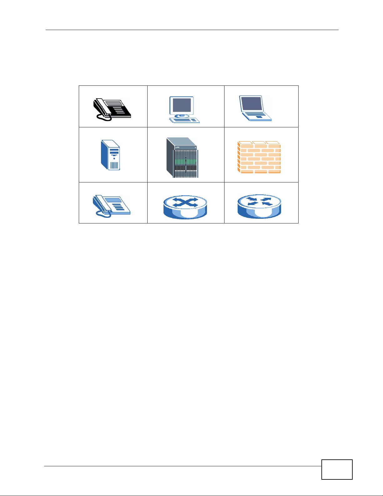
Icons Used in Figures
Figures in this User’s Guide may use the following generic icons. The V300 icon is
not an exact representation of your device.
V300 Computer Notebook computer
Server DSLAM Firewall
Telephone Switch Router
V300 Series User’s Guide
5
Page 6

Safety Warnings
• Do NOT use this product near water, for example, in a wet basement or near a
swimming pool.
• Do NOT expose your device to dampness, dust or corrosive liquids.
• Do NOT store things on the device.
• Do NOT install, use, or service this device during a thunderstorm. There is a
remote risk of electric shock from lightning.
• Connect ONLY suitable accessories to the device.
• Do NOT open the device or unit. Opening or removing co vers can expose y ou to
dangerous high voltage points or other risks. ONLY qualified service personnel
should service or disassemble this device. Please contact your vendor for further
information.
Safety Warnings
For your safety, be sure to read and follow all warning notices and
instructions.
• Make sure to connect the cables to the correct ports.
• Place connecting cables carefully so that no one will step on them or stumble
over them.
• Always disconnect all cables from this device before servicing or disassembling.
• Use ONLY an appropriate power adaptor or cord for your device. Connect it to
the right supply voltage (for example, 110V AC in North America or 230V AC in
Europe).
• Do NOT allow anything to rest on the power adaptor or cord and do NOT place
the product where anyone can walk on the power adaptor or cord.
• Do NOT use the device if the power adaptor or cord is damaged as it might
cause electrocution.
• If the power adaptor or cord is damaged, remove it from the device and the
power source.
• Do NOT attempt to repair the power adaptor or cord. Contact your local vendor
to order a new one.
• Do not use the device outside, and make sure all the connections are indoors.
There is a remote risk of electric shock from lightning.
• Do NOT obstruct the device ventilation slots, as insufficient airflow may harm
your device.
• If you wal l mount your device, m ake sure that no electrical lines, gas or water
pipes will be damaged.
6
• The PoE (Power over Ethernet) devices that supply or receive power and their
connected Ethernet cables must all be completely indoors.
V300 Series User’s Guide
Page 7
This product is recyclable. Dispose of it properly.
Safety Warnings
V300 Series User’s Guide
7
Page 8

Safety Warnings
8
V300 Series User’s Guide
Page 9

Contents Overview
Contents Overview
User’s Guide ........................................................................................................ ...................25
Introducing the V300 ................................................................................................................. 27
Hardware ................................................................................................................................... 31
Technical Reference ..............................................................................................................43
Using the LCD Screen ............................................................................................................... 45
The Phonebook ......................................................................................................................... 51
LCD Menus: Basic Settings ....................................................................................................... 53
LCD Menus: Advanced ..............................................................................................................59
The Web Configurator ............................................................................................................... 83
The Status Screens ................................................................................................................... 89
Network Setup ........................................................................................................................... 97
SIP Account Setup ................................................ ... .... ... ... ... .... ... ... ... ... .... ... ........................... 101
Phone Setup ................................ .... .........................................................................................119
The Phone Book ...................................................................................................................... 127
System ................................... ...................... ....................... ....................... .............................. 137
Logs ....................................... .................................................... .............................................. 145
Tools ........................................................................................................................................ 147
Troubleshooting ..................................................... .................................................................. 157
V300 Series User’s Guide
9
Page 10

Contents Overview
10
V300 Series User’s Guide
Page 11

Table of Contents
Table of Contents
About This User's Guide..........................................................................................................3
Document Conventions............................................................................................................4
Safety Warnings ........................................................................................................................6
Contents Overview ...................................................................................................................9
Table of Contents....................................................................................................................11
List of Figures.........................................................................................................................17
List of Tables...........................................................................................................................23
Part I: User’s Guide................................................................................ 25
Chapter 1
Introducing the V300 ..............................................................................................................27
1.1 Overview ............. ............................................. ... .... ... ... ... .... ................................................ 27
1.2 Applications ............................................... ... ... ... .... ... ... .......................................................28
1.2.1 Make Calls via Internet Telephony Service Provider .................................................. 28
1.2.2 Make Calls via IP-PBX ............................................................................................... 28
1.2.3 Make Peer-to-peer Calls .............. .... ... ... ... ................................................. ... ... .......... 29
1.3 Ways to Manage the V300 ..................................................................................................29
1.4 Good Habits for Managing the V300 ................................................................................... 30
Chapter 2
Hardware..................................................................................................................................31
2.1 Overview ............. ............................................. ... .... ... ... ... .... ................................................ 31
2.2 Physical Features ......................................................................... ... .... ... ... ... .... ................... 32
2.2.1 The LCD Screen ........................................................................................................ 37
2.2.2 Resetting the V300 .................... ............................................. .... ... ... ... .... ... ................ 37
2.3 Phone Functions .............. ............................................. ... .... ... ... ... ... .................................... 37
2.3.1 Making a Call ......................................................... .... ... ... ... ... .... ... ... .......................... 37
2.3.2 Receiving a Call .........................................................................................................38
2.3.3 Ending a Call .................................... ... ... ... .... ............................................. ... ... ... ....... 38
2.3.4 Changing the Volume .......................... ... ... ................................................................. 38
2.3.5 Muting a Call .................... ... ... ... ............................................. .... ... ... ... .... ... ... ... ... ....... 39
2.3.6 Placing a Call on Hold ................................................................................................ 39
V300 Series User’s Guide
11
Page 12

Table of Contents
2.3.7 Using Voicemail ................................................... ... ............................................. .... ...39
2.3.8 Making Conference Calls ........................................................................... ................ 39
2.3.9 Transferring a Call ............... ... ... ... .... ... ... ............................................. .... ... ... ... ... .... ...41
2.3.10 Upgrading the Phone’s Firmware ............................................................................. 41
Part II: Technical Reference.................................................................. 43
Chapter 3
Using the LCD Screen............................................................................................................45
3.1 Overview ............. ............................................. ... .... ... ... ... .... ................................................ 45
3.2 Navigation ................. .... ... ... ............................................. .... ... ... ... ... .... ... ... ... .... ................... 45
3.3 Enabling and Disabling Features ......................................................................................... 46
3.4 Entering Numbers, Letters and Symbols ............................................................................. 46
3.5 LCD Menu Overview ........................................................................................................... 47
3.6 The LCD Status Screen ....................................................................................................... 49
Chapter 4
The Phonebook.......................................................................................................................51
4.1 Overview ............. ............................................. ... .... ... ... ... .... ................................................ 51
4.1.1 What You Can Do in This Chapter ............................................................................. 51
4.2 Add a Phonebook Entry ....................................................................................................... 51
4.3 Call a Phonebook Contact ............................ ... ... .... ... ... ... .... ... ... ..........................................52
4.4 Calling a Number Not in the Phonebook ............................................................................. 52
Chapter 5
LCD Menus: Basic Settings...................................................................................................53
5.1 Overview ............. ............................................. ... .... ... ... ... .... ................................................ 53
5.1.1 What You Can Do in This Chapter ............................................................................. 53
5.2 Entering the Menu System .................................................................................................. 53
5.3 The Phonebook Menu .........................................................................................................54
5.4 The Volume Setting Menu ................................................................................................... 54
5.4.1 Volume Screen .................... ... ... ... .... ... ............................................. ... .... ... ... ... ... .......55
5.5 The System Info Menu ........................................... ... ... ... .... ... ... ... ... .... ... ... .......................... 55
5.6 The Advanced Setting Menu ............................................................................................... 56
5.7 The Reset Menu .................................................................................................................. 56
5.7.1 System Restart .................... ... ... ............................................. .... ... ... ... .... ... ................56
5.7.2 Load Factory Default .................................................................................................. 56
Chapter 6
LCD Menus: Advanced ...........................................................................................................59
6.1 Overview ............. ............................................. ... .... ... ... ... .... ................................................ 59
12
V300 Series User’s Guide
Page 13

Table of Contents
6.1.1 What You Can Do in This Chapter ............................................................................. 59
6.1.2 What You Need to Know .................................. ... ... .... ............................................. ... 60
6.2 The Advanced Setting Menu ............................................................................................... 60
6.3 The VoIP Menus ..................................................................................................................60
6.3.1 SIP Active ..................... .... ... ... ... ... .... ... ............................................. ... .... ... ... ... ... ....... 61
6.3.2 SIP Number ......................... ... ... ............................................. .... ... ... ... .... ... ................ 62
6.3.3 SIP Server Address .................................................................................................... 63
6.3.4 SIP Server Port ..........................................................................................................63
6.3.5 SIP Register Server ................................................................................................... 64
6.3.6 SIP Register Port ....................................................................................................... 65
6.3.7 SIP Service Domain ................................................................................................... 65
6.3.8 SIP User ID ................................................................................................................ 66
6.3.9 SIP Password ................................................................ ... ... ... .... ... ... ..........................67
6.4 The Auto Provision Menu ....................................................................................................67
6.4.1 Auto Provision Active .......... ... ... ... .............................................. ... ... ... .... ... ... ... ... .... ... 68
6.4.2 Protocol ........ ... .... ... ... ... .............................................. ... ... ... ... .... ... ... .......................... 68
6.4.3 Auto Provisioning Server Address ............................................................................. 69
6.4.4 Server Port ...... .... ... ... ... .... ............................................. ... ... ... .... ... ... .......................... 70
6.4.5 Expire Time ..... .... ... ... ... .... ... ............................................. ... ... .... ... ... ... ....................... 70
6.4.6 Retry Time ........................ ... ............................................. ... ... .... ... ... ... .... ................... 70
6.5 DHCP ........................................ ... ... ... ... .... ............................................. ... ... .... ... ................71
6.6 The Static IP Menu ... .... ... ... ... ................................................. ... ... ....................................... 71
6.6.1 IP Address ........................... ... ... ............................................. .... ... ... ... .... ... ................ 72
6.6.2 Gateway ....... ... .... ... ... ... .............................................. ... ... ... ... .... ... ... .......................... 73
6.6.3 Subnet Mask ....................................................... ... .... ... ... ... ... ....................................73
6.6.4 First and Second DNS Servers .................................................................................. 74
6.7 The PPPoE Menu ................................................................................................................ 74
6.7.1 PPPoE Username ......................................................................................................75
6.7.2 PPPoE Password ....................................................................................................... 76
6.8 The VLAN Menu .................................................................................................................. 76
6.9 LCD Contrast ......................... .... ... ... ... ............................................. .... ... ... ... .... ... ................77
6.10 Ring Setting ....................................................................................................................... 78
6.11 Flexworker Mode ............................................................................................................... 78
6.11.1 Using Flexworker Mode ............................................................................................ 78
6.12 Clock Alarm .......................................................................................................................80
6.13 Time Zone .......................................................................................................................... 80
6.14 Date Format ....................................................................................................................... 80
Chapter 7
The Web Configurator............................................................................................................83
7.1 Overview ............. ............................................. ... .... ... ... ... .... ................................................ 83
7.2 Accessing the Web Configurator ......................................................................................... 83
7.2.1 Title Bar .................................. ... ............................................. .... ... ... .......................... 86
V300 Series User’s Guide
13
Page 14

Table of Contents
7.2.2 Navigation Panel .......... .... ... ... ... ................................................................................. 86
7.2.3 Main Window .......................... ... ............................................. .... ... ... ... .... ... ... .............87
7.2.4 Status Bar ............................................... ... .............................................. ... ................ 87
Chapter 8
The Status Screens.................................................................................................................89
8.1 Overview ............. ............................................. ... .... ... ... ... .... ................................................ 89
8.1.1 What Yo u Can Do in this Chapter .............................................................................. 89
8.2 Status Screen ............................... ... ... ... .... ... ... ... .............................................. ... ... ... .......... 90
8.3 Packet Statistics .................................................................. ... ... ... ... .... ... ... .......................... 92
8.4 VoIP Statistics ..................................... ... .............................................. ... ... ... .... ................... 93
Chapter 9
Network Setup.........................................................................................................................97
9.1 Overview ............. ............................................. ... .... ... ... ... .... ................................................ 97
9.1.1 What You Can Do in This Chapter ............................................................................. 97
9.1.2 What You Need to Know About Network Setup ............................... ... .... ... ... ... ... .... ... 97
9.2 Internet Connection ...... ... ... ... .... ... ... ... ................................................................................. 99
9.3 Management Port ...................................... ... ... ... .... ... ........................................................100
Chapter 10
SIP Account Setup................................................................................................................101
10.1 Overview .......................................................................................................................... 101
10.1.1 What You Can Do in This Chapter . ........................................................................ 101
10.1.2 What You Need to Know About Network Setup ..................................................... 101
10.2 The SIP Settings Screen ................................................................................................. 109
10.2.1 Advanced SIP Setup Screen ............................. .......... ......... .......... .......... ......... ...... 113
10.3 SIP QoS Screen ...............................................................................................................117
Chapter 11
Phone Setup..........................................................................................................................119
11.1 Overview ...........................................................................................................................119
11.2 What You Can Do in This Chapter ....................................................................................119
11.3 Phone Settings Screen .................................................................................................... 120
11.3.1 Voice Activity Detection/Silence Suppression ........................................................ 123
11.3.2 Comfort Noise Generation .............. ........................................................................ 123
11.4 Phone Region Screen .....................................................................................................123
11.5 Speed Dial Settings Screen ............................................................................................ 124
11.6 Programmable Feature Key Settings Screen .................................................................. 125
Chapter 12
The Phone Book....................................................................................................................127
12.1 Overview .......................................................................................................................... 127
14
V300 Series User’s Guide
Page 15

Table of Contents
12.1.1 What You Can Do in This Chapter . ........................................................................ 127
12.2 Call Forward Screen ........................................................................................................ 127
12.3 Contact List Screen ......................................................................................................... 130
12.4 Group List Screen ............................................................................................................131
12.5 Block List Screen ............................................................................................................. 133
12.6 DND White List Screen ....................................................................................................135
Chapter 13
System...................................................................................................................................137
13.1 Overview .......................................................................................................................... 137
13.2 What You Can Do in This Chapter ........................................ ............. ............. ............ ..... 137
13.3 General Screen .............................................................................................................. 138
13.4 Time Setting Screen ........................................................................................................ 140
13.5 Dynamic DNS .................................................................................................................. 142
13.6 Clock Alarm Setting ......................................................................................................... 144
Chapter 14
Logs .......................................................................................................................................145
14.1 Overview .......................................................................................................................... 145
14.2 Logs Screen .................................................... .... ... ... ... .... ... ... ........................................ 145
14.3 SIP Message ................................................................................................................... 146
Chapter 15
Tools.......................................................................................................................................147
15.1 Overview .......................................................................................................................... 147
15.1.1 What You Can Do in This Chapter . ........................................................................ 147
15.2 Firmware Screen ............................................................................................................. 147
15.3 Configuration Screen ....................................................................................................... 150
15.3.1 Backup Configuration ........................ ....................................... .............................. 150
15.3.2 Restore Configuration ............................................................................................ 150
15.3.3 Save Debug Log .................................................................................................... 152
15.3.4 Back to Factory Defaults ...... ... ... .... ............................................. ... ... .... ... ... ... ... .....152
15.4 Restart Screen .................................................................................................................152
15.5 Ring Maintenance Screen ............................................................................................... 153
15.6 Packet Mirror Screen ....................................................................................................... 154
Chapter 16
Troubleshooting....................................................................................................................157
16.1 Overview .......................................................................................................................... 157
16.2 Power, Hardware Connections, and LEDs .............................. ... ... .... ... ... ... .... ... ... ... ........157
16.3 Internet Access ................................................................................................................ 160
16.4 Phone Calls and VoIP ......................................................................................................161
V300 Series User’s Guide
15
Page 16

Table of Contents
Appendix A Product Specifications.......................................................................................165
Appendix B Setting Up Your Computer’s IP Address...........................................................171
Appendix C Pop-up Windows, JavaScripts and Java Permissions......................................201
Appendix D IP Addresses and Subnetting...........................................................................209
Appendix E Legal Information..............................................................................................219
Appendix F Open Software Announcements.......................................................................223
Appendix G Customer Support ............................................................................................229
Index.......................................................................................................................................235
16
V300 Series User’s Guide
Page 17

List of Figures
List of Figures
Figure 1 Internet Telephony Service Provider Application ............................................ ... ....................... 28
Figure 2 IP-PBX Application .................................................................................................................. 29
Figure 3 Peer-to-peer Calling ................................................................................................................. 29
Figure 4 Front Panel Hardware ............................................................................................................. 32
Figure 5 Side Panel ................................................................................................................................ 34
Figure 6 Rear Panel ............................................................................................................................... 35
Figure 7 Base Panel Hardware ............................................................................................................. 36
Figure 8 Example: DHCP ....................................................................................................................... 46
Figure 9 LCD Status Screen ...................................................................................................................49
Figure 10 Flexworker Icon ...................................................................................................................... 49
Figure 11 LCD Contact Record ............................................................................................................... 51
Figure 12 LCD Contact Record: Save .................................................................................................... 52
Figure 13 LCD Dial Screen .................................................................................................................... 52
Figure 14 LCD Contact List Screen ....................................................................................................... 52
Figure 15 LCD Menu Setting .................................................................................................................. 53
Figure 16 LCD Menu: Phonebook.......................................................................................................... 54
Figure 17 LCD Menu: Volume Setting ................................................................................................... 54
Figure 18 LCD Menu: Volume Screen ................................................................................................... 55
Figure 19 LCD Menu: System Info ........................................................................................................ 55
Figure 20 LCD Menu: Reset .................................................................................................................. 56
Figure 21 LCD Menu: Reset: System Restart ........................................................................................ 56
Figure 22 LCD Menu: Reset: System Restart: Confirm ......................................................................... 56
Figure 23 LCD Menu: Reset: Reset Default .................... ... ... .... ... ... ... ............................................. ....... 56
Figure 24 LCD Menu: Reset: Reset Default: Confirm ........................................................................... 57
Figure 25 LCD Menu: Advanced Setting................................................................................................ 60
Figure 26 LCD Menu: Admin Password Entry ....................................................................................... 61
Figure 27 LCD Menu: SIP Active............................................................................................................ 61
Figure 28 LCD Menu: SIP Active............................................................................................................ 62
Figure 29 LCD Menu: SIP Number......................................................................................................... 62
Figure 30 LCD Menu: SIP Number - Edit ............................................................ .... ... ... ... ...................... 62
Figure 31 LCD Menu: SIP Server Address............................................................................................. 63
Figure 32 LCD Menu: SIP Server Address - Edit ....................................................................... ... ... .... .. 63
Figure 33 LCD Menu: SIP Server Port ................................................................................................... 63
Figure 34 LCD Menu: SIP Server Port - Edit.......................................................................................... 64
Figure 35 LCD Menu: SIP Register Server ............................................................................................ 64
Figure 36 LCD Menu: SIP Register Server Address - Edit..................................................................... 64
Figure 37 LCD Menu: SIP Register Port ................................................................................................ 65
Figure 38 LCD Menu: SIP Register Port - Edit....................................................................................... 65
V300 Series User’s Guide
17
Page 18

List of Figures
Figure 39 LCD Menu: SIP Service Domain............................................................................................ 65
Figure 40 LCD Menu: SIP Service Domain - Edit................................................................................... 66
Figure 41 LCD Menu: SIP User ID ........................................................................................................ 66
Figure 42 LCD Menu: SIP User ID - Edit................................................................................................ 66
Figure 43 LCD Menu: Authentication Password..................................................................................... 67
Figure 44 LCD Menu: Authentication Password - Edit ........................................................................... 67
Figure 45 LCD Menu: Admin Password Entry ....................................................................................... 67
Figure 46 LCD Menu: DHCP ................................................................................................................. 68
Figure 47 LCD Menu: DHCP ................................................................................................................ 68
Figure 48 LCD Menu: Protocol ............................................................................................................. 68
Figure 49 LCD Menu: Serv Addr .......................................................................................................... 69
Figure 50 LCD Menu: Serv Addr Error ................................................................................................. 69
Figure 51 LCD Menu: Serv Port ........................................................................................................... 70
Figure 52 LCD Menu: Expire Time ........................................................................................................ 70
Figure 53 LCD Menu: Retry Time .......................................................................................................... 70
Figure 54 LCD Menu: DHCP ................................................................................................................ 71
Figure 55 LCD Menu: Static IP............................................................................................................... 71
Figure 56 LCD Menu: IP Address........................................................................................................... 72
Figure 57 LCD Menu: IP Address - Edit ................................................................................................. 72
Figure 58 LCD Menu: Gateway............................................................................................................. 73
Figure 59 LCD Menu: Gateway - Edit..................................................................................................... 73
Figure 60 LCD Menu: Subnet Mask ....................................................................................................... 73
Figure 61 LCD Menu: Subnet Mask - Edit ............................................................................................. 73
Figure 62 LCD Menu: First / Second DNS ............................................................................................. 74
Figure 63 LCD Menu: First / Second DNS - Edit.................................................................................... 74
Figure 64 LCD Menu: PPPoE ................................................................................................................ 75
Figure 65 LCD Menu: PPPoE Username............................................................................................... 75
Figure 66 LCD Menu: PPPoE Username - Edit .....................................................................................75
Figure 67 LCD Menu: PPPoE Password................................................................................................ 76
Figure 68 LCD Menu: PPPoE Password - Edit .....................................................................................76
Figure 69 LCD Menu: VLAN ................................................................................................................... 77
Figure 70 LCD Menu: LCD Contrast .............................................................................. .... ... ... .............77
Figure 71 LCD Menu: Ring Type ........................................................................................................... 78
Figure 72 LCD Menu: Flexworker Mode .......................... ................... .................... ................... ............. 78
Figure 73 LCD Menu: Clock Alarm ......................................................................................................... 80
Figure 74 LCD Menu: Time Zone ........................................................................................................... 80
Figure 75 LCD Menu: Date Format ........................................................................................................ 81
Figure 76 Password Screen .................................................................................................................. 83
Figure 77 Change Password Screen ........................ ................. ................ ............. ................ ................ 84
Figure 78 The Status Screen .................................................................................................................85
Figure 79 Status Screen ......................................................................................................................... 90
Figure 80 Packet Statistics ..................................................................................................................... 92
Figure 81 VoIP Statistics .........................................................................................................................93
18
V300 Series User’s Guide
Page 19

List of Figures
Figure 82 Network > Internet Connection ............................................................................................... 99
Figure 83 Network > Mgnt Port ............................................................................................................. 100
Figure 84 SIP User Agent ............................. ... ... ... ... .... ... ... ................................................. ................. 103
Figure 85 SIP Proxy Server .......................................... ... ... ................................................. ................. 104
Figure 86 SIP Redirect Server ......................... ... ... ... .... ... ... ... .... ... ... ... .................................................. 105
Figure 87 STUN .................................................................................................................................... 106
Figure 88 DiffServ: Differentiated Service Field .................................................................................... 108
Figure 89 VoIP > SIP > SIP Settings .....................................................................................................110
Figure 90 VoIP > SIP > SIP Settings > Advanced .................................................................................113
Figure 91 VoIP > SIP > QoS ..................................................................................................................117
Figure 92 VoIP > Phone > Phone Settings ........................................................................................... 120
Figure 93 VoIP > Phone > Region ................................ ... ... ... .... ... ... ... .................................................. 123
Figure 94 Phone Book > Speed Dial .. ... ... .... ... ... ... ................................................. ... ... ... .... ... ... ... ........124
Figure 95 Phone Book > Programmable Feature Key Settings ............................................................ 125
Figure 96 VoIP > Phone Book > Call Forward ...................................................................................... 128
Figure 97 VoIP > Phone Book > Contact List ....................................................................................... 130
Figure 98 VoIP > Phone Book > Group List ......................................................................................... 132
Figure 99 VoIP > Phone Book > Block List .......................................................................................... 133
Figure 100 VoIP > Phone Book > DND White List ...............................................................................135
Figure 101 Maintenance > System > General ......................................................................................138
Figure 102 Maintenance > Time Setting ............................................................................................... 140
Figure 103 Maintenance > DDNS ......................................................................................................... 143
Figure 104 Maintenance > System > Clock Alarm Setting ................................................................... 144
Figure 105 Maintenance > Logs ........................................................................................................... 145
Figure 106 Maintenance > SIP Message ............................................................................................. 146
Figure 107 Maintenance > Tools > Firmware Upload ........................................................................... 148
Figure 108 Upload Warning ..................................................................................................................148
Figure 109 Network Temporarily Disconnected ....................................................................................149
Figure 110 Upload Error Message ... ... ... ... .... ... ............................................. ... ... .... .............................. 149
Figure 111 Maintenance > Tools > Configuration .................................................................................150
Figure 112 Configuration Upload Successful .......................................................................................151
Figure 113 Temporarily Disconnected ..................................................................................................151
Figure 114 Configuration Restore Error ................................................................................................ 152
Figure 115 Maintenance > Tools > Restart ........................................................................................... 152
Figure 116 Maintenance > Tools > Ring Maintenance ......................................................................... 153
Figure 117 Packet Mirror Example ....................................................................................................... 154
Figure 118 Maintenance > Tools > Packet Mirror .................................................................................154
Figure 119 Wall-mounting Example ......................................................................................................169
Figure 120 Masonry Plug and M4 Tap Screw .......................................................................................169
Figure 121 Windows XP: Start Menu .................................................................................................... 172
Figure 122 Windows XP: Control Panel ............................................................................................... 172
Figure 123 Windows XP: Control Panel > Network Connections > Properties ......................... ... ... .... . 173
Figure 124 Windows XP: Local Area Connection Properties ............................................................... 173
V300 Series User’s Guide
19
Page 20

List of Figures
Figure 125 Windows XP: Internet Protocol (TCP/IP) Properties .......................................................... 174
Figure 126 Windows Vista: Start Menu ................................................................................................. 176
Figure 127 Windows Vista: Control Panel ............................................................................................ 176
Figure 128 Windows Vista: Network And Internet ................................................................................ 176
Figure 129 Windows Vista: Network and Sharing Center ..................................................................... 177
Figure 130 Windows Vista: Network and Sharing Center ..................................................................... 177
Figure 131 Windows Vista: Local Area Connection Properties ............................................................ 178
Figure 132 Windows Vista: Internet Protocol Version 4 (TCP/IPv4) Properties ................................... 179
Figure 133 Mac OS X 10.4: Apple Menu .............................................................................................. 181
Figure 134 Mac OS X 10.4: System Preferences ................................................................................. 181
Figure 135 Mac OS X 10.4: Network Preferences ...............................................................................182
Figure 136 Mac OS X 10.4: Network Preferences > TCP/IP Tab. ........................................................ 182
Figure 137 Mac OS X 10.4: Network Preferences > Ethernet ................ ................................... ........... 183
Figure 138 Mac OS X 10.4: Network Utility .......................................................................................... 184
Figure 139 Mac OS X 10.5: Apple Menu .............................................................................................. 185
Figure 140 Mac OS X 10.5: Systems Preferences ............................................................................... 185
Figure 141 Mac OS X 10.5: Network Preferences > Ethernet ................ ................................... ........... 186
Figure 142 Mac OS X 10.5: Network Preferences > Ethernet ................ ................................... ........... 187
Figure 143 Mac OS X 10.5: Network Utility .......................................................................................... 188
Figure 144 Ubuntu 8: System > Administration Menu .......................................................................... 189
Figure 145 Ubuntu 8: Network Settings > Connections ...................... .... ............................................. . 189
Figure 146 Ubuntu 8: Administrator Account Authentication ................................................................ 190
Figure 147 Ubuntu 8: Network Settings > Connections ...................... .... ............................................. . 190
Figure 148 Ubuntu 8: Network Settings > Properties ........................................................................... 191
Figure 149 Ubuntu 8: Network Settings > DNS ...................................................................................192
Figure 150 Ubuntu 8: Network Tools .................................................................................................... 193
Figure 151 openSUSE 10.3: K Menu > Computer Menu ..................................................................... 194
Figure 152 openSUSE 10.3: K Menu > Computer Menu ..................................................................... 195
Figure 153 openSUSE 10.3: YaST Control Center .............................................................................. 195
Figure 154 openSUSE 10.3: Network Settings .................................................................................... 196
Figure 155 openSUSE 10.3: Network Card Setup ............................................................................... 197
Figure 156 openSUSE 10.3: Network Settings .................................................................................... 198
Figure 157 openSUSE 10.3: KNetwork Manager ................................................................................. 199
Figure 158 openSUSE: Connection Status - KNetwork Manager ........................................................ 199
Figure 159 Pop-up Blocker ................................................................................................................... 201
Figure 160 Internet Options: Privacy .................................................................................................... 202
Figure 161 Internet Options: Privacy .................................................................................................... 203
Figure 162 Pop-up Blocker Settings ..................................................................................................... 204
Figure 163 Internet Options: Security ................................................................................................... 205
Figure 164 Security Settings - Java Scripting ....................................................................................... 206
Figure 165 Security Settings - Java ......................................................................................................207
Figure 166 Java (Sun) .......................................................................................................................... 208
Figure 167 Network Number and Host ID ............................................................................................210
20
V300 Series User’s Guide
Page 21

List of Figures
Figure 168 Subnetting Example: Before Subnetting ....................................... ... .... ... ... ... ..................... 213
Figure 169 Subnetting Example: After Subnetting ....................................... ... ... .... ... ... ... ..................... 214
V300 Series User’s Guide
21
Page 22

List of Figures
22
V300 Series User’s Guide
Page 23

List of Tables
List of Tables
Table 1 Models Covered ........................................................................................................................ 27
Table 2 Front Panel Hardware ............................................................................................................... 33
Table 3 Side Panel Hardware ................................................................................................................ 35
Table 4 Rear Panel Hardware ............................................................................................................... 36
Table 5 Base Panel Hardware ............................................................................................................... 36
Table 6 Keypad Characters ................................................................................................................... 47
Table 7 LCD Menu Overview ................................................................................................................. 47
Table 8 LCD Menu: Volume Setting ....................................................................................................... 54
Table 9 LCD Menu: System Info ............................................................................................................ 55
Table 10 LCD Menu: SIP Account Configuration ................................................................................... 61
Table 11 LCD Menu: SIP Account Configuration ...................................................................................68
Table 12 LCD Menu: Static IP ................................................................................................................ 69
Table 13 LCD Menu: Static IP ................................................................................................................ 71
Table 14 LCD Menu: SIP Account Configuration ................................................................................... 72
Table 15 LCD Menu: PPPoE .................................................................................................................75
Table 16 LCD Menu: SIP Account Configuration ................................................................................... 75
Table 17 LCD Menu: VLAN ................................................................................................................... 77
Table 18 Web Configurator Icons in the Title Bar .................................................................................. 86
Table 19 Navigation Panel Summary .................................................................................................... 86
Table 20 S tatus Screen .......................................................................................................................... 90
Table 21 Packet S tatistics ...................................................................................................................... 92
Table 22 VoIP Statistics ......................................................................................................................... 94
Table 23 Private IP Address Ranges ....... .... ... ... ... ... .... ... ... ................................................. ... ... ... ..........97
Table 24 Network > Internet Connection .............. ... ................................................. ... ... .... ... ... ... ..........99
Table 25 Network > Mgnt Port ............................................................................................................. 100
Table 26 SIP Call Progression ................. .... ... ................................................ ... .... ... ... ... .... ... ..............102
Table 27 VoIP > SIP > SIP Settings ......................................................................................................111
Table 28 VoIP > SIP > SIP Settings > Advanced Setup .......................................................................114
Table 29 VoIP > SIP > QoS ..................... .... ... ... ... ... .... ... ... ... .... ............................................................117
Table 30 VoIP > Phone > Phone Settings ........................................................................................... 121
Table 31 VoIP > Phone > Region ........................................................................................................ 123
Table 32 Phone Book > Speed Dial ..................................................................................................... 124
Table 33 Phone Book > Programmable Feature Key Settings ............................................................ 125
Table 34 VoIP > Phone Book > Call Forward ...................................................................................... 128
Table 35 VoIP > Phone Book > Contact List ................................... ... .... ... ... ... ... .... .............................. 130
Table 36 VoIP > Phone Book > Group List .......................................................................................... 132
Table 37 VoIP > Phone Book > Block List ...................... ... ... .... ... ... ... .... ... ... ... ... .... .............................. 133
Table 38 VoIP > Phone Book > DND White List .................................................................................. 136
V300 Series User’s Guide
23
Page 24

List of Tables
Table 39 Maintenance > System > General ...... ... ... .... ... ... ... .... ... ... ... .... ... ... ... ... .... ... ... ... .... ... ... ... ... ..... 138
Table 40 Maintenance > Time Setting .. ... .... ... ... ... ... .... ... ... ... .... ... ... ... .... ... ........................................... 140
Table 41 Maintenance > System > DDNS ........................................................................................... 143
Table 42 Maintenance > System > Clock Alarm Setting ........................ ................ ................ .............. 144
Table 43 Maintenance > Logs ............................................................................................................. 145
Table 44 Maintenance > SIP Message ................................................................................................ 146
Table 45 Maintenance > Tools > Firmware Upload ............................................................................. 14 8
Table 46 Maintenance > Tools > Configuration > Restore ...................................................................150
Table 47 Maintenance > Tools > Ring Maintenance ............................................................................ 153
Table 48 Maintenance > Tools > Ring Maintenance ............................................................................ 155
Table 49 Hardware Specifications ....................................................................................................... 165
Table 50 Firmware Specifications ........................................................................................................ 166
Table 51 S tandards Supported ............................................................................................................167
Table 52 IP Address Network Number and Host ID Example ........ ... .... ... ... ... ... .... ... ... ... .... ... ... ... ... .... . 210
Table 53 Subnet Masks ........................................................................................................................211
Table 54 Maximum Host Numbers . ... ... ... .... ... ... ... ... .... ... ... ... .... ... ... ... .... ... ............................................211
Table 55 Alternative Subnet Mask Notation .........................................................................................212
Table 56 Subnet 1 ................................................................................................................................ 215
Table 57 Subnet 2 ................................................................................................................................ 215
Table 58 Subnet 3 ................................................................................................................................ 215
Table 59 Subnet 4 ................................................................................................................................ 215
Table 60 Eight Subnets ............................................ .... ... ... .................................................................. 216
Table 61 24-bit Network Number Subnet Planning ................................................ ... ... ... .... ... ... ........... 216
Table 62 16-bit Network Number Subnet Planning ................................................ ... ... ... .... ... ... ........... 217
Table 63 Open Source Components ........................................................................ ... ... .... ... ... ... ........227
24
V300 Series User’s Guide
Page 25

PART I
User’s Guide
25
Page 26

26
Page 27
CHAPTER 1
Introducing the V300
1.1 Overview
This chapter introduces the main applications and features of the V300. It also
introduces the ways you can manage the V300.
The V300 is an IP phone that allows you to make phone calls over the Internet.
Sending voice signals over the Internet is called Voice over IP (VoIP). VoIP allows
you to call other IP phones, mobile phones or landlines all over the world.
The V300 is packed with features - including multiple lines, phonebook,
conference calls, call transfer, call hold, and many more.
You can configure and manage the V300 directly, using its multi-function keypad
and LCD screen. Alternatively, access the internal web configurator using a
computer connected to the network for remote administrative configuration.
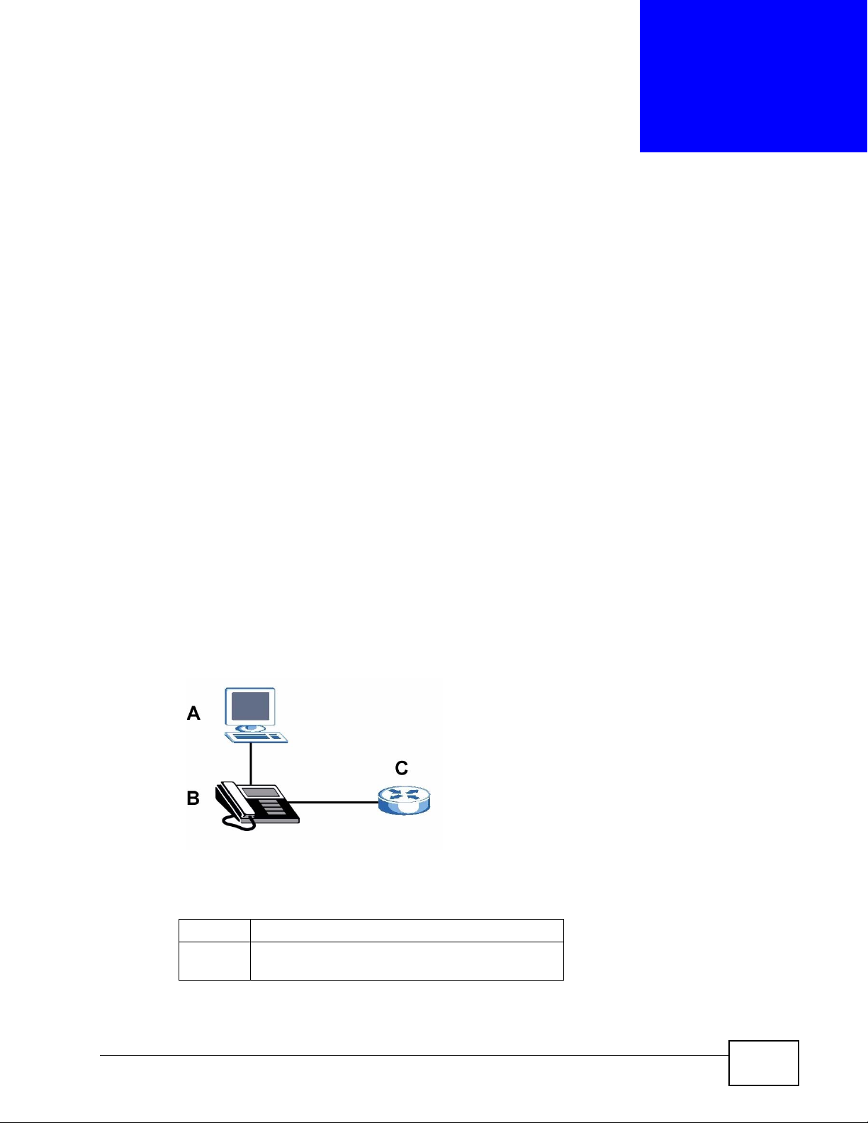
The V300’s Ethernet ports allow you to connect it to your Local Area Network
(LAN) and your computer. Your computer can access the LAN through the V300, as
shown in the following figure. A is your computer, B is your V300 and C is your
modem or router.
At the time of writing, this User’s Guide covers the following models.
Table 1 Models Covered
V300 IP phone.
V301 IP phone with Power over Ethernet (PoE)
capability.
V300 Series User’s Guide
27
Page 28
Chapter 1 Introducing the V300
1.2 Applications
Here are some examples of how you can use your V300.
1.2.1 Make Calls via Internet Telephony Service Provider
In a home or small office environment, you can use the V300 to make and recei ve
VoIP telephone calls through an Internet Telephony Service Provider (ITSP).
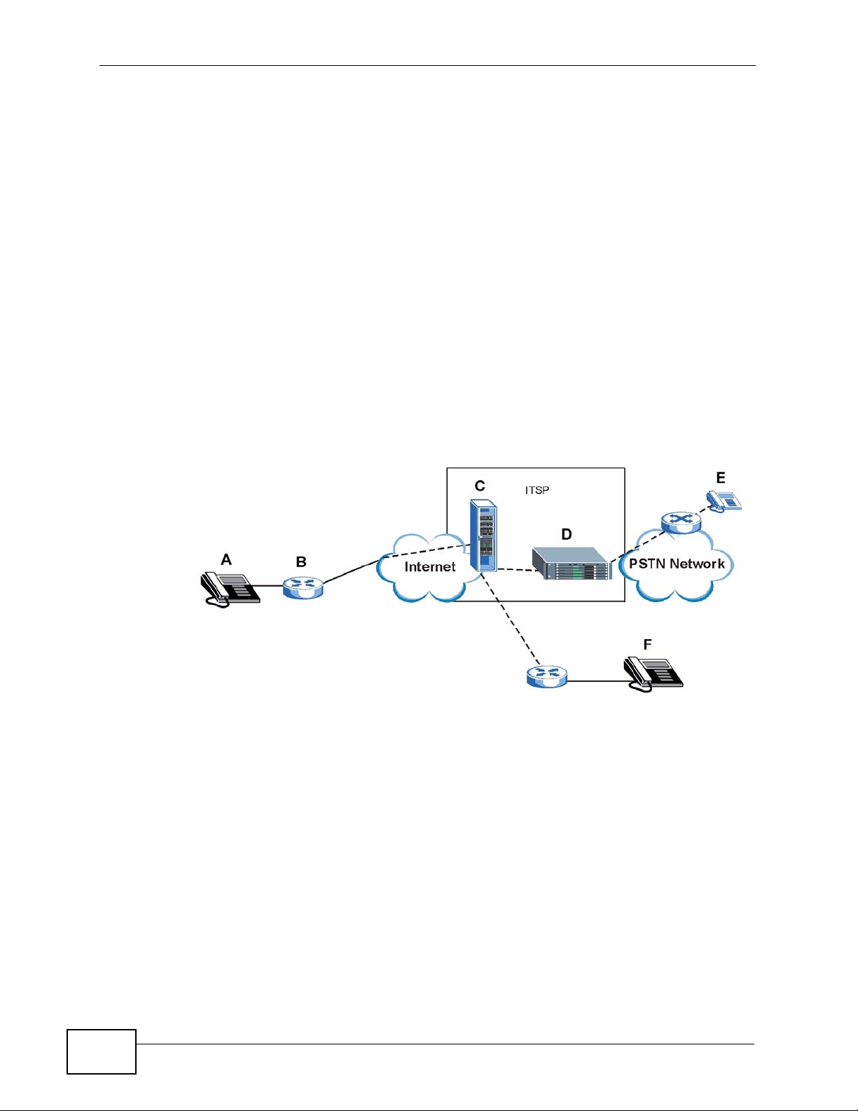
The following figure shows a basic example of how you make a VoIP call through
an ITSP. In this example, you make a call from your V300 (A in the figure), which
sends the call through your modem or router (B) to the In ternet and the ITSP’s
SIP server (C). The VoIP call server forwards calls to PSTN (Public Switched
Telephone Network) phones through a trunking gateway (D) to phones on the
PSTN network (E). The VoIP call server also forwards calls to IP phones (F)
through the Internet.
Figure 1 Internet Telephony Service Provider Application
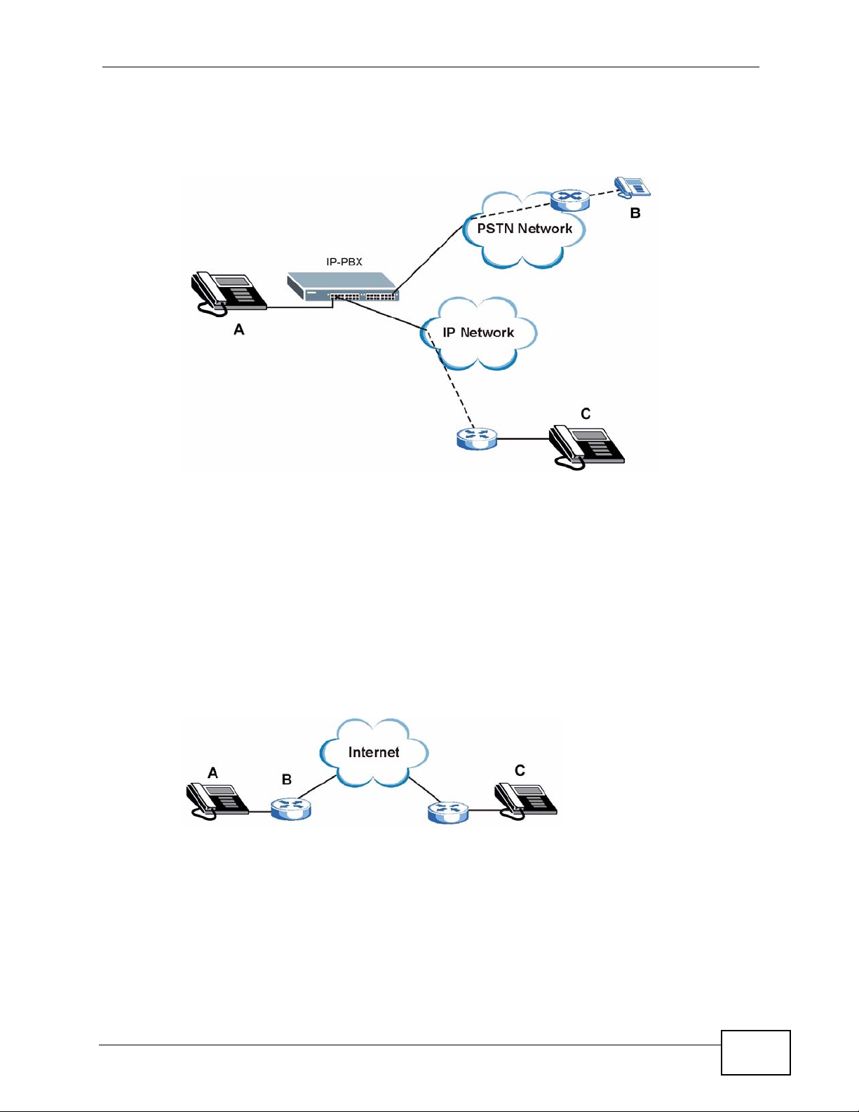
1.2.2 Make Calls via IP-PBX
If your company has an IP-PBX (Internet Protocol Private Branch Exchange), you
can use the V300 to make and receive VoIP telephone calls through it.
In this example, you make a call from your V300 (A in the figu re), which sends it
to the IP-PBX. The IP-PBX forwards calls to PSTN phones (B) on the PSTN
28
V300 Series User’s Guide
Page 29
Chapter 1 Introducing the V300
network. The IP-PBX also forwards calls to IP phone s (C) th rough an IP network
(this could include the Internet).
Figure 2 IP-PBX Application
1.2.3 Make Peer-to-peer Calls
Use the V300 to make a call to the recipient’s IP address without using a SIP
server. Peer-to-peer calls are also called “Point to Point” or “IP-to-IP” calls. You
must know the peer’s IP address in order to do this.
The following figure shows a basic example of how you would make a peer-to-peer
VoIP call. You make a call on your V300 (A), which sends your call throu gh your
modem or router (B) and the Internet to the peer VoIP device (C).
Figure 3 Peer-to-peer Calling
1.3 Ways to Manage the V300
Use any of the following methods to manage the V300.
• Hardware keys. Use the control keys and LCD menus on the V300 for basic
configuration.
V300 Series User’s Guide
29
Page 30

Chapter 1 Introducing the V300
• Web Configurator. This is recommended for everyday management of the V300
using a (supported) web browser.
• FTP. Use File Transfer Protocol for firmware upgrades and configuration backup/
restore.
• SPTGEN. SPTGEN is a text configuration file that you can edit and upload to the
device. This is especially convenient if you need to configure many devices of
the same type.
1.4 Good Habits for Managing the V300
Do the following things regularly to make the V300 more secure and to manage
the V300 more effectively.
• Change the web configurator password. Use a password that’ s not easy to guess
and that consists of different types of characters, such as numbers and letters.
• Write down the password and put it in a safe place.
• Keep the V300 in a safe place. The LCD menus are not password-protected, so
anyone using the phone can access your phonebook, SIP account information,
etc.
• Back up the configuration (and make sure you know how to restore it).
Restoring an earlier working configuration may be useful if the device becomes
unstable or even crashes. If you forget y our password, you will hav e to reset the
V300 to its factory default settings to access the web configur ator. If you backed
up an earlier configuration file, you would not have to totally re-configure the
V300. You could simply restore your last configuration.
30
V300 Series User’s Guide
Page 31

CHAPTER 2
Hardware
2.1 Overview
This chapter describes the V300’s physical features, and how to use the phone
functions.
V300 Series User’s Guide
31
Page 32

Chapter 2 Hardware
2.2 Physical Features
This section discusses the V300’s front, side, rear and base panel hardware
features. See your Quick Start Guide for descriptions of how to set up the V300’s
hardware and network connections.
Figure 4 Front Panel Hardware
32
V300 Series User’s Guide
Page 33

Chapter 2 Hardware
The following table describes the front panel hardware.
Table 2 Front Panel Hardware
LABEL DESCRIPTION
1 Handset cradle
2 LCD (Liquid Crystal Display) screen.
3 Menu Press this to display the V300’s configuration menu. When the
menu displays, you can press this key again to exit the menu.
The menu is not accessible when a call is in progress.
4 Navigator Use this to move around the V300’s screens. Press to go up
one line in a menu, and press to go down one line. In the
configuration menu, press to enter a menu or continue to the
next menu, and press to go back to the previous menu.
When the V300 is not in the configuration menu, you can press
or to view the previous calls and use to delete the
records or save them as the contacts in your phone book. When
the V300 is connected to the Internet and not in the
configuration menu, use or to select the SIP account you
want to use to make calls.
5 Phonebook Use this to display the list of contacts stored in the V300. If
there is no contact stored in the V300, the message
“Phonebook is empty” displays. To add, edit or remove an entry
in the phonebook, use the web configurator. See Chapter 12 on
page 127 for more information. In a menu, use this to clear the
previous settings.
6 Action keys HOLD Use this to put a call on hold. Press it a
second time to take the call off hold.
CONFERENCE Use this to set up a conference call between
the V300 and two other phones, or to split a
conference call you set up into two separate
calls.
TRANSFER Use this to transfer a call to another phone.
HANG UP Use this to end a call.
REDIAL Use this to dial the last number that was
called from the V300.
SEND Use this to start a call, once you have
entered the phone number.
V300 Series User’s Guide
33
Page 34
Chapter 2 Hardware
Table 2 Front Panel Hardware (continued)
LABEL DESCRIPTION
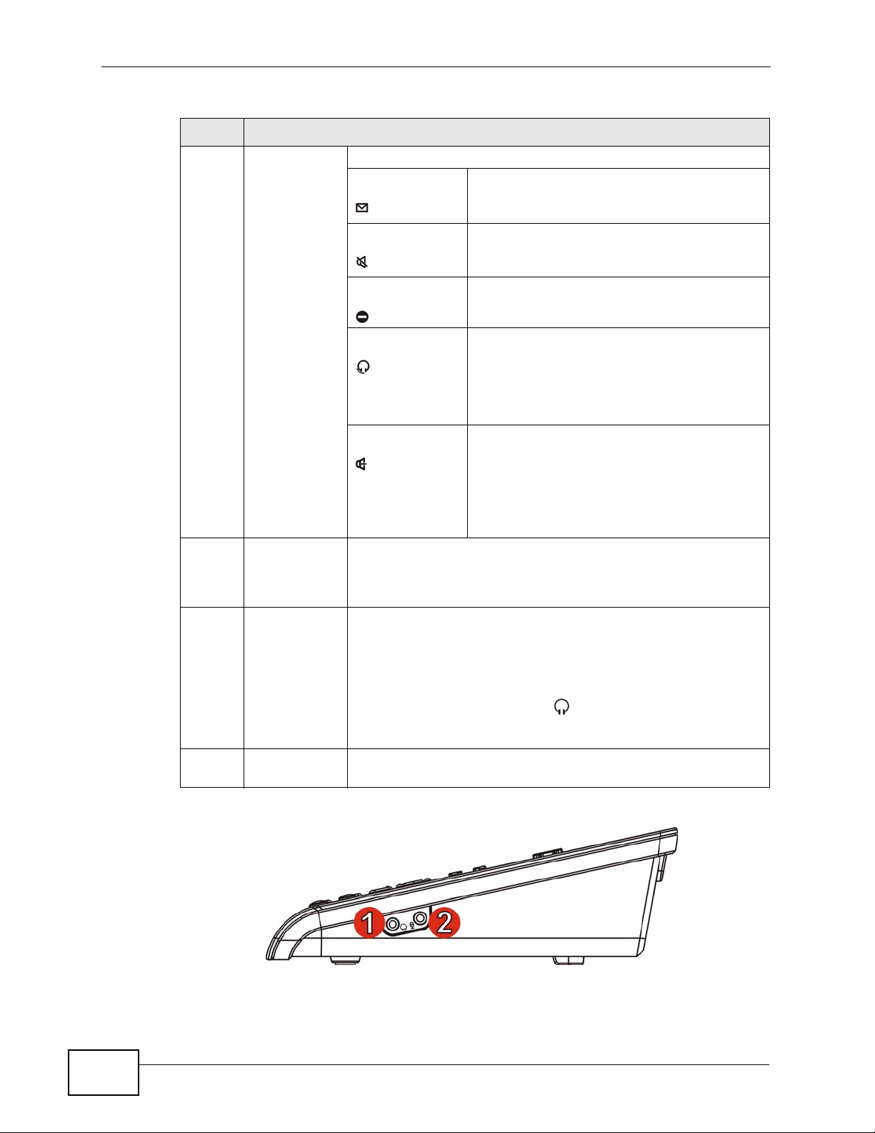
7 Function keys The LEDs (lights) in these keys illuminate when they are activ e.
VOICEMAIL Use this to check your voicemail messages,
once the voicemail number is configured in
the V300.
MUTE Use this to mute the current call. The V300
no longer transmits a signal, but you can still
hear the incoming signal.
DND Use this to toggle the Do Not Disturb
function on or off.
HEADSET Use this to activate a line using the headset,
or to transfer a call to the headset when
using the handset or the speakerphone.
When a line is active and you are using the
headset, press this key to hang up.
SPEAKER Use this to activate a line using the
speakerphone, or to transfer a call to the
speakerphone when using the handset or the
headset.
When a line is active and you are using the
speakerphone, press this key to hang up.
8Alphanumeric
keypad
9 Volume keys Use the + key to increase the volume, and use the - key to
10 Microphone The microphone is active when the V300 is in speakerphone
Use this to enter numbers, letters and symbols. Use the # key
to switch between Number mode, Uppercase mode, Lowercase
mode and Symbol mode. In the configuration menu, use a
numeric key (from 1 to 5) to go to a specific menu directly.
decrease it.
• When you use the handset, these keys control the handset’s
listening volume.
• When you use the headset, these keys control the listening
volume on the headphone ( ) port on the V300.
• When you use the speakerphone, these keys control the
internal speaker volume.
mode.
Figure 5 Side Panel
34
V300 Series User’s Guide
Page 35
Chapter 2 Hardware
The following table describes the side panel hardware.
Table 3 Side Panel Hardware
LABEL DESCRIPTION
1 Headphone socket Use this to connect a headset’s earphone jack,
headphones, or an external loudspeaker.
2 Microphone socket Use this to connect a headset’s microphone jack, or an
external microphone.
Figure 6 Rear Panel
V300 Series User’s Guide
35
Page 36

Chapter 2 Hardware
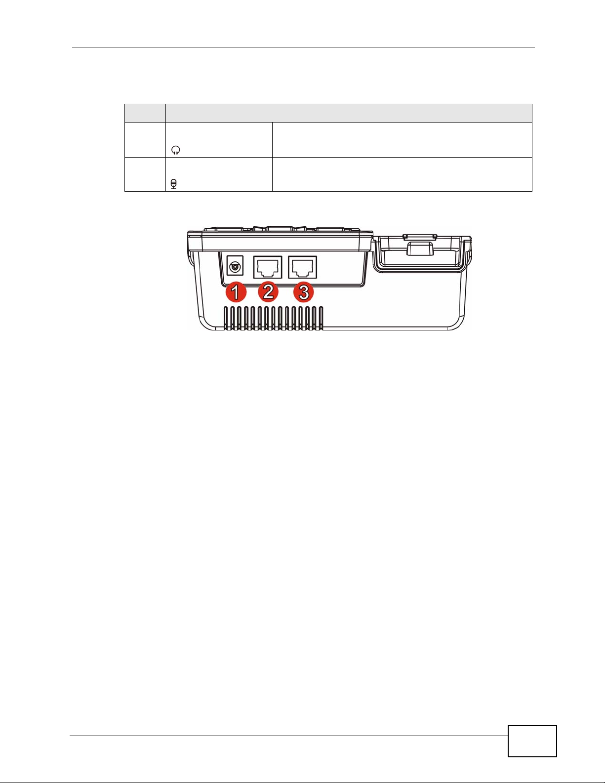
The following table describes the rear panel hardware.
Table 4 Rear Panel Hardware
LABEL DESCRIPTION
1 Power socket Attach the included power adaptor, if you are not using
2 LAN port Use an Ethernet cable to connect to your network.
3 PC port Use an Ethernet cable to connect a computer for
Figure 7 Base Panel Hardware
Power over Ethernet (V301 only). See the product
specifications appendix for power supply specifications.
Note: Use only the power adaptor and cable that
came with your V300.
configuration, or to access the Internet.
36
The following table describes the rear panel hardware.
Table 5 Base Panel Hardware
LABEL DESCRIPTION
1 Wall-mounting holes Use these to hang the V300 on a wall. See the wall-
mounting appendix for details.
2 Handset port Use this to attach the included handset cable’s RJ-11
connector.
V300 Series User’s Guide
Page 37

Table 5 Base Panel Hardware
LABEL DESCRIPTION
3 Reset button Use this to return the V300 to its factory default
4 Cable channel Clip the V300’s handset cable into this.
2.2.1 The LCD Screen
When the V300 is on, the LCD (Liquid Crystal Display) screen shows either the
status screen, a phonebook screen, or a configuration menu.
The LCD menus allow you to configure and control the V300. See Chapter 3 on
page 45 for details on configuring the V300 via the LCD menus.
Chapter 2 Hardware
settings. See the appendix on product specifications for
the default settings.
Note: If you do this, all configuration changes and
data on the V300 are lost, including
phonebook records.
2.2.2 Resetting the V300
If you want to reset the V300 to its factory defaults (if you forgot the web
configurator password, for example) press and hold the RESET button for
approximately ten seconds. The V300 restarts automatically.
Note: If you reset the V300, all settings return to their factory defaults. All data stored
in the V300 (phonebook entries, for example) will be lost.
2.3 Phone Functions
This section describes how to use your V300’s basic telephone functions. See
Chapter 3 on page 45 for information on the using the V300’s LCD screen menus
and Chapter 4 on page 51 for information on how to use the V300’s phonebook.
2.3.1 Making a Call
1 Start the call:
• If you want to use the handset:
Lift the handset.
• If you want to use the speakerphone:
Press the SPEAKER key.
V300 Series User’s Guide
37
Page 38

Chapter 2 Hardware
• If you want to use a headset:
Press the HEADSET key.
2 Check that you can hear a dial tone.
3 Enter the number you want to call. If you have numbers stored in the V300’s
phone book, you can use the navigator to select from the list of entries.
4 Press the yellow SEND key.
During the call:
• If you are using the headset or the speakerphone, you can switch to the
handset by lifting it off the hook.
• If you are using the handset or the speakerphone, you can switch to the
headset by pressing the HEADSET key.
• If you are using the handset or a headset, you can switch to the V300’s
speakerphone by pressing the SPEAKER key.
Note that the call ends if you are using the speakerphone and p ress the SPEAKER
key, or if you are using the headset and press the HEADSET key.
2.3.2 Receiving a Call
When the phone rings, do one of the following:
• Pick up the handset to receive the call using the handset.
•Press the SPEAKER key to receive the call using the internal speakerphone.
•Press the HEADSET key to receive the call using an external headset.
2.3.3 Ending a Call
When you want to end a call, press the HANG UP key. Alternatively, do one of the
following:
• If you are using the handset, replace it in the cradle.
• If you are using the internal speakerphone, press the SPEAKER key.
• If you are using an external headset, press the HEADSET key.
2.3.4 Changing the Volume
Use the VOLUME + key to increase the volume, and use the VOLUME - key to
decrease it.
38
• When there is no line active on the V300, the v o lume keys control the ringing
volume.
V300 Series User’s Guide
Page 39

• When the handset is off hook, the keys control the handset’s speaker volume.
• When the speakerphone is active, the keys control the speaker volume.
• When the headset is active, the keys control the headset’s speaker (earpiece)
volume.
2.3.5 Muting a Call
When you mute a call on the V300 you can hear the incoming signal (the sound
from the other end of the line) but you do not transmit a signal (the person on the
other end of the line cannot hear you). It does not matter whether you are using
the handset, the internal speakerphone or an external headset.
Press the MUTE key once to mute a call. Press it a second time to return to the
call.
2.3.6 Placing a Call on Hold
Chapter 2 Hardware
When you place a call on hold, you neither receive nor transmit a signal. If your
phone system is configured to use the Music on Hold feature, the person on the
other end of the line hears the preconfigured music (or other audio). Otherwise,
they hear nothing.
Press the HOLD key once to place a call on hold. Press it a second time to return
to the call.
2.3.7 Using Voicemail
Once you have configured your SIP account’s voicemail number on the V300, you
can press the VOICEMAIL key to check your messages.
Use the VoIP > SIP > SIP Settings screen to set the voicemail account number.
See Section 10.2 on page 109 for more information.
2.3.8 Making Conference Calls
Take the following steps to make a three-way conference call.
1 Either start a call, or receive a call. Make sure you know which line the call is
using.
2 Ensure the call is active (you can talk with the other person). Press the
Conference key. This “marks” the first call you want to m i x i nt o the conference
call.
V300 Series User’s Guide
39
Page 40

Chapter 2 Hardware
3 Select another line. You can either receive an incoming call, make another
outgoing call, or resume an existing call that you previously put on hold.
4 Ensure the call is active and press the Conference key again. The three-way
conference call begins. All three parties can talk with one another.
Note: Do not press any other keys between step 2 and step 3. If you do, you will have
Note: You cannot have a conference call and a transferred call ongoing at the same
Note: If the person who started the conference call leaves, the remaining parties can
to start again.
time.
continue talking in the same conference.
40
V300 Series User’s Guide
Page 41

2.3.9 Transferring a Call
Take the following steps to transfer an ongoing call to another phone number.
1 During the ongoing call, press the Transfer key.
2 The next available line automatically activates. Ensure you can hear a dial tone.
3 Dial the number to which you want to transfer the call.
4 To transfer the call, either:
• Wait until you hear the ringing tone, then simply put down the handset, press
the Speaker key or the Headset key (depending on which you are using) to
end the call. The call is transferred. This is known as a blind or unsupervised
transfer.
• Wait for the other person to answer, then press transfer key again to end the
call. This is known as a consultant or supervised transfer, and allows you to
ask the other person whether they want to receive the call or not.
Chapter 2 Hardware
2.3.10 Upgrading the Phone’s Firmware
When it is time to upgrade your phone’s firmware, your telephone network
administrator will configure the IP PBX to which the V300 is connected to
automatically check your phone’s existing firmware and compare it to the
firmware on an official ZyXEL server. If your firmware’s version number does not
match, the IP PBX will then initiate the upgrade process:
1 When the IP PBX is ready to process your phone, it rings you while the phone is on
the hook. As soon as you answer, an automated message asks if you want to
change your V300’s firmware.
2 Enter * 9 9 # on the V300’s keypad to answer ‘Yes’.
Enter # 9 9 # on the V300’s keypad to answer ‘No’.
3 If you entered ‘Yes’, then the phone begins downloading the new firmware from
the IP PBX. The download and install process may take some time, depending on
the size of the update and any network congestion.
4 When the download and install process completes, the V300 restarts. You may
need to log into your account again.
Note: Do not turn off or attempt to use your V300 during a firmware update.
V300 Series User’s Guide
41
Page 42

Chapter 2 Hardware
42
V300 Series User’s Guide
Page 43

PART II
Technical Reference
43
Page 44

44
Page 45

CHAPTER 3
Using the LCD Screen
3.1 Overview
This chapter shows you how to use and configure the V300 via the LCD screen
menu system.
Note: See the web configurator section of this guide for background information on
the V300’s features.
3.2 Navigation
Use the following keys to move around the V300’s LCD screen menu system.
• The navigator.
Use this to move the cursor up and down (when selecting a menu item) or left
and right (when editing a field).
• The alphanumeric keypad.
Enter a menu item’s number to jump to that item (single-digit numbers only).
•The MENU key.
Use this to access the V300's configuration menu or exit the menu.
•The PHONEBOOK key.
Use this to return to view the stored contacts, or delete a character when
editing a field.
Note: When there is more than one entry in a menu, one or two arrows display on the
right side of the LCD screen. If you can scroll down to see other entries
displays, if you can scroll up to see other entries displays, and if you can
scroll up or down to see other entries displays. These arrows are not shown
in this User’s Guide.
V300 Series User’s Guide
45
Page 46

Chapter 3 Using the LCD Screen
3.3 Enabling and Disabling Features
Many of the V300’s LCD screen menus allow you check a feature’s settings and
then edit the setting. Take the following steps to check a feature’s current setting
and then enable or disable the feature. This example uses the DHCP feature.
1 Select the feature you want to configure. In this example, press MENU to enter
the menu system, then select Adv Setting. In the Adv Setting menu, select
DHCP.
The following screen displays:
Figure 8 Example: DHCP
1. DHCP
Off
2 To change the setting to ON, press .
Note: If later you decide you want to use static IP or PPPoE, then you do not need to
come into the DHCP menu to disable it; rather, just go into one of those other
menus and enable one of them. This automatically turns DHCP off.
3.4 Entering Numbers, Letters and Symbols
When you enter information into the V300 (when setting up a phonebook entry,
for example) you may need to enter different kinds of characters. The
alphanumeric keypad has four input modes:
•Number mode
•Uppercase mode
•Lowercase mode
•Symbol mode
Use the # key to cycle between modes.
Note: Not all modes are available in all screens.
46
When you press a key to enter a character, wait a short time until th e c ursor
moves on to the next space. Press a key multiple times to access the different
characters. For example, in Uppercase mode press 9 four times to enter “
V300 Series User’s Guide
Z”.
Page 47

Chapter 3 Using the LCD Screen
The following table shows the numbers, letters and symbols you can enter.
Table 6 Keypad Characters
MODE
NumberUppercaseLowercase Symbol
KEY
1 1 [NONE] [NONE] ! | #
22 A B C a b c : ; “
3 3D E Fd e f / \ ?
4 4 G H I g h i @ % &
5 5 J K L j k l . ‘ ,
6 6 M N O m n o + ^ =
7 7 P Q R S p q r s ~ - _
8 8 T U V t u v ( )
9 9 W X Y Z w x y z < >
* . .. $ *
0 0 [NONE] [NONE] [SPACE]
# [CYCLE MODE]
3.5 LCD Menu Overview
This section shows the LCD menus, and describes what you can do with each.
Press the Navigator up or down to access the V300’s LCD menu system.
Table 7 LCD Menu Overview
MENU DESCRIPTION
Phonebook Use this menu to view details of your contacts.
Vol Setting
[Volume
Setting]
Speaker Volume Use this menu to set the loudness of the internal
speaker.
Phone Volume Use this menu to set the loudness of the V300’s
handset.
Ring Volume Use this menu to set the loudness of the V300’s
ringtone.
Headset Volume Use this menu to set the loudness of an external
headset you plug into the V300.
V300 Series User’s Guide
47
Page 48

Chapter 3 Using the LCD Screen
Table 7 LCD Menu Overview (continued)
MENU DESCRIPTION
System Info IP Address Use this to see the IP address, subnet mask, gateway,
Subnet Mask
Gateway
1st DNS
2nd DNS
MAC Use this to see the MAC (Media Access Control
F/W Version Use this to see the version number of the firmware the
Adv Setting
[Advanced
Setting]
Reset Restart Phone Use this to restart the V300.
VoIP1 Use this menu to set up the first Voice over Internet
VoIP2 Use this menu to set up the second Voice over
Auto Prov Use this menu to set the phone to be configured
DHCP Use this menu to have the V300 get an IP address
Static IP Use this menu to give your V300 an IP address.
PPPoE Use this menu to configure your PPPoE username and
VLAN Use this menu to configure the V300’s voice VLAN ID
LCD Contrast Use this menu to adjust the contrast of the V300’s
Ring Setting Use this menu to select a ring tone for your V300.
Flexwork Use this menu to “carry” your V300 settings with you
Clock Alarm Use this menu to configure the V300’s three built-in
Time Zone Use this to choose the time zone of your location.
Date Format Use this to select the date format that shows on the
and DNS settings currently assigned to the V300.
Address) of the V300.
V300 is currently using.
(VoIP) account.
Internet (VoIP) account.
automatically through auto provisioning.
automatically.
password, if provided by your Internet Service
Provider or network administrator.
and priority.
screen.
when you change locations but are still using a
compatible V300 phone.
alarm clocks.
LCD.
48
Using this feature does NOT return the V300 to its
factory defaults.
Reset Default Use this to return the V300 to its factory defaults.
V300 Series User’s Guide
Page 49

3.6 The LCD Status Screen
When you first turn on the V300 or make a call, the status screen displays. The
status screen is divided into two main sections, as shown below.
Figure 9 LCD Status Screen
09:45 2010-01-01
SIP1 1234
In the status screen, the upper line displays the time and date configured on the
V300, and the lower line displays information about the SIP account. The SIP
account’s name displays if it is successfully registered. If it has tried to register
but failed, NoReg displays. If the SIP account is not enabled (see Section 6.3.1 on
page 61) NoUse displays.
When the phone is in Flexworker mode (see Section 6.11 on page 78 for more), a
small ‘F’ icon on the right side.
Chapter 3 Using the LCD Screen
Figure 10 Flexworker Icon
V300 Series User’s Guide
49
Page 50

Chapter 3 Using the LCD Screen
50
V300 Series User’s Guide
Page 51

CHAPTER 4
The Phonebook
4.1 Overview
Use the V300’s phonebook to view or store the names and phone numbers of your
contacts.
The following sections describe how to add and use phonebook entries.
Note: The V300 can hold a maximum of 200 private phone numbers and 200 public
phone numbers. Public phone numbers are provided by the PBX to which your
phone is connected, while private numbers are the ones you enter into your
phone memory yourself.
4.1.1 What You Can Do in This Chapter
• Add a call record to your phonebook (Section 4.2 on page 51).
• Call a previously saved entry in your phonebook (Section 4.3 on page 52).
• Call a number that is not in your phonebook (Section 4.4 on page 52).
4.2 Add a Phonebook Entry
Take the following steps to add a call record to the V300’s phonebook.
1 Press the Navigator up or down to display the previous called numbers.
Figure 11 LCD Contact Record
1. 889763
15:30 2010-01-01
V300 Series User’s Guide
51
Page 52

Chapter 4 The Phonebook
2 Press , select Save to Phone and press again to store this record as a contact
entry in your phone book
Figure 12 LCD Contact Record: Save
889763
Save to Phone
Note: You can view the stored contact entry by pressing the PHONEBOOK key.
4.3 Call a Phonebook Contact
In order to call a number you previously entered into the V300’s phonebook, first
activate a line (lift the handset, or press the SPEAKER or HEADSET key). The
following screen displays. Ensure you can hear a dial tone.
Figure 13 LCD Dial Screen
Line 1 Dial:
_
Press the PHONEBOOK key. The Contact List screen displays.
Figure 14 LCD Contact List Screen
1. Ann
1234
Scroll to the contact name or number you want to call, then press the SEND key
to dial the number.
Note: The numbers that display to the left of a cont act’ s name in this screen are inde x
numbers only - you cannot use them to select an entry to call.
4.4 Calling a Number Not in the Phonebook
When you want to call a number that is not in your V300’s phonebook, activate a
line, dial the number and press the SEND key to start the call.
52
V300 Series User’s Guide
Page 53

CHAPTER 5
LCD Menus: Basic Settings
5.1 Overview
This chapter discusses how to set up your V300 using the internal configuration
menus.
5.1.1 What You Can Do in This Chapter
•The Menu system lets you configure your V300 (Section 5.2 on page 53).
•The Phonebook menu lets you view a list of your contacts (Section 5. 3 on page
54).
•The Volume menu lets you set the loudness of the speakers (Section 5.4 on
page 54).
•The Advanced Setting menu let you configure a range of more detailed phone
options, such as your VoIP account and PPPoE settings (Section 5.6 on page
56).
•The Reset menu lets you restart the phone or restore its defaults (Section 5.7
on page 56).
5.2 Entering the Menu System
Press MENU to enter the menu system. The Menu Setting screen displays as
shown below.
Figure 15 LCD Menu Setting
Menu Setting:
1. Phonebook
See the rest of this chapter for details on configuring each menu. For background
information, see the relevant chapter in the web configurator section of this User’s
Guide.
Note: When a menu has more than one option, only the first option can be seen on
the LCD screen. Use the navigator to scroll down to the other options.
V300 Series User’s Guide
53
Page 54

Chapter 5 LCD Menus: Basic Settings
5.3 The Phonebook Menu
Use the phonebook to view a list of your contacts.
Select MENU > Phonebook. The following screen displays. This is the same
function as pressing the actual PHONEBOOK button.
Figure 16 LCD Menu: Phonebook
1. Ann
1234
If you want to add, edit or remove an entry in the phonebook, use the web
configurator. See Chapter 7 on page 83 for more infor m ation.
If you want to add a call record in the phonebook or call a phonebook contact, see
Chapter 4 on page 51.
5.4 The Volume Setting Menu
Use these menus to set the loudness of the V300’s audio equipment.
Select MENU > Vol Setting. The following screen displays.
Figure 17 LCD Menu: Volume Setting
2. Vol Control
1. Speaker Volume
The following table describes the labels in this screen.
Table 8 LCD Menu: Volume Setting
LABEL DESCRIPTION
Speaker Volume Select this to set the internal speakerphone volume. This controls
both the internal speaker and the internal microphone.
Phone Volume Select this to set the handset volume. This controls both the
handset’s speaker and its microphone.
Ring Volume Select this to set the volume of the V300’s ringtone. This setting
applies to all configured group rings.
Headset Volume Select this to set the volume of an attached headset (or any
device connected to the external speaker and/or microphone
sockets). This controls both the handset’s speaker (earpiece) and
its microphone.
54
V300 Series User’s Guide
Page 55

5.4.1 Volume Screen
When you select one of the options in the Volume Setting menu, a screen similar
to the following displays. This example uses the Speaker Volume screen.
Figure 18 LCD Menu: Volume Screen
Speaker Vol:-+
Use the VOLUME keys to increase or decrease the volume. Press or to go
back to the previous menu when you are done.
5.5 The System Info Menu
The System Info menu allows you to quickly check some of your V300’s settings.
These settings are read-only.
Chapter 5 LCD Menus: Basic Settings
Select MENU > System Info. The following screen displays.
Press
settings.
to enter the System Info menu and use the arrows to view the system
Figure 19 LCD Menu: System Info
Menu Setting:
3. System Info
The following table describes the labels in this menu.
Table 9 LCD Menu: System Info
LABEL DESCRIPTION
IP Address This is the IP address currently assigned to the V300. This
displays 0.0.0.0 if DHCP is disabled.
Subnet Mask This is the subnet mask currently configured on the V300. This
displays 0.0.0.0 if DHCP is disabled.
Gateway This is the IP address of the device on the network your V300
uses to access the Internet. This displays 0.0.0.0 if DHCP is
disabled.
1st DNS This is the primary DNS (Domain Name System) server your
V300 uses. This displays 0.0.0.0 if DHCP is disabled.
2nd DNS This is the secondary (backup) DNS server your V300 uses. This
displays 0.0.0.0 if DHCP is disabled.
F/w Version This is the version number of the firmware currently running on
the V300. You can upload new firmware using the web
configurator.
V300 Series User’s Guide
55
Page 56

Chapter 5 LCD Menus: Basic Settings
5.6 The Advanced Setting Menu
Use this menu to configure network and SIP account settings. See Chapter 6 on
page 59 for information on the Advanced Setting menu.
5.7 The Reset Menu
Use this menu to restart the V300 or reset the V300 t o the fa ctory defaults . Press
MENU > Reset and then to access the Reset menu. The following screen
displays.
Figure 20 LCD Menu: Reset
Menu Setting:
5. Reset
5.7.1 System Restart
Use this screen to restart the V300 without turning the power off.
1 Select RestartPhone.
Figure 21 LCD Menu: Reset: System Restart
5. Reset
1. RestartPhone
2 Press .and the following screen displays. Press the 1 key to restart the V300 or
press the 2 key to return to the previous menu wi thout restarting the V300.
Figure 22 LCD Menu: Reset: System Restart: Confirm
Yes ->Press 1
No ->Press 2
5.7.2 Load Factory Default
Use this screen to reset the V300 back to the factory defaults.
56
1 Select ResetDefault.
Figure 23 LCD Menu: Reset: Reset Default
5. Reset
2. ResetDefault
V300 Series User’s Guide
Page 57

Chapter 5 LCD Menus: Basic Settings
2 Press .and the following screen displays. Press the 1 key to clear all user-
entered information and return to the factory defaults. Otherwise, press the 2 key
to go back to the previous menu without resetting the V300.
Figure 24 LCD Menu: Reset: Reset Default: Confirm
Yes ->Press 1
No ->Press 2
V300 Series User’s Guide
57
Page 58

Chapter 5 LCD Menus: Basic Settings
58
V300 Series User’s Guide
Page 59

CHAPTER 6
LCD Menus: Advanced
6.1 Overview
This chapter shows you how to use the V300’s LCD menus.
6.1.1 What You Can Do in This Chapter
•The VoIP menus let you set up your voice accounts (Section 6.3 on page 60).
•The Auto Provision menu lets you set up the V300 to receive its configur ation
data automatically from the SIP server to which it is registered (Section 6.4 on
page 67).
•The DHCP menu lets you have the V300 get an IP address automatically from a
DHCP server on the network (Section 6.5 on page 71).
•The Static IP menu lets you manually configure your V300’s IP address, subnet
mask and gateway settings (Section 6.6 on page 71).
•The PPPoE menu lets you configure your V300’s PPPoE username and
password, if it is a PPPoE client (Section 6.7 on page 74).
•The VLAN menu lets you enable VLAN and configure the V300’s voice VLAN ID
and priority (Section 6.8 on page 76).
•The LCD Contrast screen lets you adjust the contr ast setting on the V300’s LC D
(Section 6.9 on page 77).
•The Ring Setting screen lets you choose a ring tone (Section 6.10 on page 78).
•The Flexworker screen allows you to “carry” your V300 settings with you when
you change locations (Section 6.11 on page 78).
•The Clock Alarm screen allows you to view the V300’s three internal clock
alarm configurations (Section 6.12 on page 80).
•The Time Zone screen lets you choose the time zone of your location (Section
6.13 on page 80).
•The Date Format screen lets you select the date format that shows on the
V300’s LCD screen (Section 6.14 on page 80).
V300 Series User’s Guide
59
Page 60

Chapter 6 LCD Menus: Advanced
6.1.2 What You Need to Know
The following terms and concepts may help you as you read through this chapter.
HTTP
HyperText Transfer Protocol is commonly used on the Internet. HTTP is the
primary protocol used for web sites and web browsers. It is also prone to certain
kinds of attacks.
HTTPS
HyperText Transfer Protocol over Secure Socket Layer, or HTTP over SSL is a web
protocol that encrypts and decrypts web pages. Secure Socket Layer (SSL) is an
application-level protocol that enables secure transactions of data by ensuring
confidentiality (an unauthorized party cannot read the transferred data),
authentication (one party can identify the other party) and data integrity (you
know if data has been changed).
TFTP
Trivial File Transfer Protocol (TFTP) is an Internet file transfer protocol similar to
FTP (File Transfer Protocol), but is scaled back in functionality to require fewer
resources to run. TFTP uses the UDP (User Datagram Protocol) rather than TCP
(Transmission Control Protocol).
6.2 The Advanced Setting Menu
Press MENU to access the LCD screen menu system, select Adv Setting and
press . The following screen displays.
Figure 25 LCD Menu: Advanced Setting
4. Setting
1. VoIP1
6.3 The VoIP Menus
60
Use these menus to set up your V300 to set up and use a Voice over Internet
(VoIP) account.
V300 Series User’s Guide
Page 61

Chapter 6 LCD Menus: Advanced
Note: Once you have configured the fields in these menus with the correct
information, the V300 must register with the SIP server . You may need to restart
the V300 to do this.
Note: Enter information in these menus exactly as you received it from your VoIP
service provider . If you were not given inf ormation for any menu or field, leave it
at its default setting.
Select Adv Setting > VoIP1 or VoIP2 and press , upon which you are
prompted to enter the V300’s admin password (the defaul t is ‘1234’)
a mistake, press the PHONEBOOK to delete your entry one number at a time.
. If you make
Figure 26 LCD Menu: Admin Password Entry
Password:
Press once again after entering the password. If correct, the following screen
displays.
Figure 27 LCD Menu: SIP Active
1. SIP1/2 Active
On
See the following sections for more information on each menu in this screen.
Table 10 LCD Menu: SIP Account Configuration
SIP Active see Section 6.3.1 on page 61
SIP Num see Section 6.3.2 on page 62
Serv Addr see Section 6.3.3 on page 63
Serv Port see Section 6.3.4 on page 63
Reg Addr see Section 6.3.5 on page 64
Reg Port see Section 6.3.6 on page 65
Domain see Section 6.3.7 on page 65
User ID see Section 6.3.8 on page 66
Password see Section 6.3.9 on page 67
6.3.1 SIP Active
Use this screen to set whether the SIP account linked is active or not.When the
account is inactive, you cannot make or receive calls on the V300 using that
account. Y ou can, however, use the other account, assuming it is active. If both
are inactive, then the V300 cannot make or receive any phone calls whatsoever.
V300 Series User’s Guide
61
Page 62

Chapter 6 LCD Menus: Advanced
Select Adv Setting > VoIP1 or VoIP2 > SIP Active and enter the password
when prompted. The following screen displays.
Figure 28 LCD Menu: SIP Active
1. SIP1/2 Active
On
Press to toggle between the ON and OFF settings.
6.3.2 SIP Number
Use this to see and edit the SIP number for your SIP account.
Note: If you have a SIP account like “1234567@voip-provider.com”, the SIP Number
is “1234567”.
Select Adv Setting > VoIP1 or VoIP2 > SIP1 Num. The following screen
displays.
Figure 29 LCD Menu: SIP Number
2. SIP1 Num
If a SIP account number is already configured, it displays. Otherwise, no SIP
number displays. Press to edit the SIP number, or press to return to the
previous screen.
6.3.2.1 SIP Number - Edit
Press in the SIP Num screen. The following screen displays.
Figure 30 LCD Menu: SIP Number - Edit
2 SIP1 Num 1
_
Use PHONEBOOK to clear the previously-sa ved settings if an y. Enter the new SIP
account number and press to save the change. Alternatively, press to return
to the previous screen.
62
V300 Series User’s Guide
Page 63

6.3.3 SIP Server Address
Use this menu to see and edit the IP address of the SIP server for your account.
Select Adv Setting > VoIP1 or VoIP2 > Serv Addr. The following screen
displays.
Figure 31 LCD Menu: SIP Server Address
3. Serv Addr
The IP address of the SIP server already configured on the V300 displays. If no IP
address is already configured, none displays. Press to edit the SIP server
address, or press to return to the previous screen.
6.3.3.1 SIP Server Address - Edit
Press in the Serv Addr screen. The following screen displays.
Chapter 6 LCD Menus: Advanced
Figure 32 LCD Menu: SIP Server Address - Edit
3. Serv Addr 1
_
Use PHONEBOOK to clear the previously-sa ved settings if an y. Enter the new SIP
server address and press to save the change. Alternatively, press to return to
the previous screen.
6.3.4 SIP Server Port
Use this screen to see and edit the port on the this account’s SIP server used for
SIP calls. Select Adv Setting > VoIP1 or VoIP2 > Serv Port. The following
screen displays.
Figure 33 LCD Menu: SIP Server Port
4. Serv Port
5060
This screen displays the SIP server port number on the V300. The default is 5060.
Press to edit the SIP server port number, or press to return to the previous
screen.
Note: Make no changes in this screen unless your service provider told you to.
V300 Series User’s Guide
63
Page 64

Chapter 6 LCD Menus: Advanced
6.3.4.1 SIP Server Port - Edit
Press in the Serv Port screen. The following screen displays.
Figure 34 LCD Menu: SIP Server Port - Edit
4. Serv Port 1
5060_
Use PHONEBOOK to clear the previously-sa ved settings if an y. Enter the new SIP
server port number (from 1024 to 65535) and press to save the change.
Alternatively, press to return to the previous screen.
Note: The port number can consist of numerals (0 ~ 9) only.
6.3.5 SIP Register Server
Use this menu to see and edit the IP address of the server your SIP service
provider uses to register the V300. Select Adv Setting > VoIP1 or Vo IP2 > Reg
Addr. The following screen displays.
Figure 35 LCD Menu: SIP Register Server
5. Reg Addr
The IP address of the SIP register server already configured on the V300 displays.
If no IP address is already configured, none displays. Press to edit the SIP
register server address, or press to return to the previous screen.
6.3.5.1 SIP Register Server - Edit
Press in the Reg Addr screen. The following screen displays.
Figure 36 LCD Menu: SIP Register Server Address - Edit
5. Reg Addr 1
_
Use PHONEBOOK to clear the previously-sa ved settings if an y. Enter the new SIP
register server address and press to save the change. Alternatively, press to
return to the previous screen.
64
V300 Series User’s Guide
Page 65

6.3.6 SIP Register Port
Use this screen to see and edit the listening port on the SIP register server for
calls from this account. Select Adv Setting > VoIP1 or VoIP2 > Re g P ort . The
following screen displays.
Figure 37 LCD Menu: SIP Register Port
6. Reg Port
5060
This screen displays the SIP register server port number on the V300. The default
is 5060. Press to edit the SIP register server port number, or press to return
to the previous screen.
Note: Make no changes in this screen unless your service provider told you to.
6.3.6.1 SIP Register Port - Edit
Chapter 6 LCD Menus: Advanced
Press in the Reg Port screen. The following screen displays.
Figure 38 LCD Menu: SIP Register Port - Edit
6. Reg Port 1
5060_
Use PHONEBOOK to clear the previously-sa ved settings if an y. Enter the new SIP
server port number (from 1024 to 65535) and press to save the change.
Alternatively, press to return to the previous screen.
Note: The port number can consist of numerals (0 ~ 9) only.
6.3.7 SIP Service Domain
Use this to see and edit the SIP service domain configured for your SIP account.
The SIP service domain of the VoIP service provider (the company that lets you
make phonecalls over the Internet) is the domain name in a SIP URI. For example,
if the SIP address is “1122334455@voip-provider.com”, then “voip-provider.com”
is the SIP service domain.
Select Adv Setting > VoIP1 or VoIP2 > Domain. The following screen displays.
Figure 39 LCD Menu: SIP Service Domain
7. Domain
V300 Series User’s Guide
65
Page 66

Chapter 6 LCD Menus: Advanced
If a SIP domain is already configured on the V300, it displays in this screen. If no
SIP domain is already configured, none displays. Press to edit the SIP domain,
or press to return to the previous screen.
6.3.7.1 SIP Service Domain - Edit
Press in the Domain screen. The following screen displays.
Figure 40 LCD Menu: SIP Service Domain - Edit
7. Domain 1
_
Use PHONEBOOK to clear the previously-sa ved settings if an y. Enter the new SIP
service domain. If you have a SIP account like “1234567@v oip-pro vider.com”, the
SIP service domain is “voip-provider.com”. Press to save the change.
Alternatively, press to return to the previous screen.
6.3.8 SIP User ID
A SIP account’s user ID is its username. Select Adv Setting > VoIP1 or VoIP2 >
User ID to see and edit the SIP user name for your SIP account. The following
screen displays.
Figure 41 LCD Menu: SIP User ID
8. User ID
If a SIP authentication ID is already co nf ig ured on the V300, it displays in this
screen. If no SIP authentication ID is already configured, none displays . Press
to edit the SIP authentication ID, or press to return to the previous screen.
6.3.8.1 SIP Authentication ID - Edit
Press in the User ID screen. The following screen displays.
Figure 42 LCD Menu: SIP User ID - Edit
8. User ID 1
_
66
Use PHONEBOOK to clear the previously-sa ved settings if an y. Enter the new SIP
authentication ID. Press to save the change. Alternatively, press to return to
the previous screen.
V300 Series User’s Guide
Page 67

6.3.9 SIP Password
Use this screen to see and edit the password for your SIP account. Select Adv
Setting > VoIP1 or VoIP2 > Password. The following screen displays.
Figure 43 LCD Menu: Authentication Password
9. Password
If a SIP authentication password is already configured on the V300, it displays in
this screen as a row of asterisks (*). If no SIP authentication password is already
configured, no asterisks display. Each asterisk rep res ents one character of the
password configured on the V300. Press to edit the SIP authentication
password, or press to return to the previous screen.
6.3.9.1 Authentication Password - Edit
Press in the Password screen. The following screen displays.
Chapter 6 LCD Menus: Advanced
Figure 44 LCD Menu: Authentication Password - Edit
9. Password 1
_
Use PHONEBOOK to clear the previously-sa ved settings if an y. Enter the new SIP
authentication password. Press to save the change. Alternatively, press to
return to the previous screen.
6.4 The Auto Provision Menu
The auto provision menu lets you set up the V300 to receive its configuration data
automatically from the SIP server to which it is registered.
Select Adv Setting > Auto Prov and press , upon which you are prompted to
enter the V300’s admin password (the default is ‘1234’)
press the PHONEBOOK key to delete your entry one number at a time.
Figure 45 LCD Menu: Admin Password Entry
. If you make a mistake,
Password:
V300 Series User’s Guide
67
Page 68

Chapter 6 LCD Menus: Advanced
Press once again after entering the password. If correct, the following screen
displays.
Figure 46 LCD Menu: DHCP
1. Active
See the following sections for more information on each menu in this screen.
Table 11 LCD Menu: SIP Account Configuration
Active see Section 6.4.1 on page 68
Protocol see Section 6.4.2 on page 68
Serv Addr see Section 6.4.3 on page 69
Serv Port see Section 6.4.4 on page 70
Expire Time see Section 6.4.5 on page 70
Retry Time see Section 6. 4.6 on page 70
6.4.1 Auto Provision Active
When the auto provision feature is set to ON, the V300 then receives all the
information it needs to be immedia t el y usable from the SIP server to which it is
registered. This is a zero-configuration option that automatically determines the
phone’s extension number, IP address, and other relevant network data. However,
before this feature can be fully utilized the SIP server must be configured in
advance to provide the settings needed by the V300.
Select Adv Setting > Auto Prov > Active and enter the password when
prompted. The following screen displays.
Figure 47 LCD Menu: DHCP
1. Active
Press to toggle auto provisioning OFF and ON.
6.4.2 Protocol
68
Select Adv Setting > Auto Prov > Protocol. The following screen displays.
Figure 48 LCD Menu: Protocol
2. Protocol
V300 Series User’s Guide
Page 69

Press to toggle auto provisioning HTTP, HTTPS, and TFTP.
The following table describes the labels in this screen.
Table 12 LCD Menu: Static IP
LABEL DESCRIPTION
HTTP Select this option if the SIP server to which your V300 is
registered uses HTTP as its auto provisioning protocol.
HTTPS Select this option if the SIP server to which your V300 is
registered uses HTTPS as its auto provisioning protocol.
TFTP Select this option if the SIP server to which your V300 is
registered uses TFTP as its auto provisioning protocol.
6.4.3 Auto Provisioning Server Address
Select Adv > Auto Prov > Serv Addr. The follow ing screen displays.
Figure 49 LCD Menu: Serv Addr
Chapter 6 LCD Menus: Advanced
3. Serv Addr
Press to configure the auto provisioning server’s IP address.
If you make a mistake, use the PHONEBOOK key to delete your entry one number
at a time (you can use the asterix key [*] to enter periods). Press again to save
the address.
If the IP address that you entered is malformed or contains mistakes, then the
following error message displays.
Figure 50 LCD Menu: Serv Addr Error
3. Serv Addr 1
Invalid IP Addr
Otherwise, the IP address that you entered is locked into the phone until manually
edited again later. You can edit or delete the IP address by entering this screen
and using the PHONEBOOK key to clear entries.
V300 Series User’s Guide
69
Page 70

Chapter 6 LCD Menus: Advanced
6.4.4 Server Port
Select Adv > Auto Prov > Serv Port. The following screen displays.
Figure 51 LCD Menu: Serv Port
4. Serv Port
8080
The default is ‘8080’. Press to change this.
If you make a mistake, use the PHONEBOOK key to delete your entry one number
at a time (you can use the asterix key [*] to enter periods). Press again to save
the port number.
6.4.5 Expire Time
Select Adv > Auto Prov > Expire Time. The following screen displays.
Figure 52 LCD Menu: Expire Time
5. Expire Time
3600
The default is ‘3600’ seconds, or 60 minutes. Press to change this. The
maximum allowed is 259200 seconds, or 72 hours/3 days.
If you make a mistake, use the PHONEBOOK key to delete your entry one number
at a time. Press again to save the expire time.
6.4.6 Retry Time
Select Adv > Auto Prov > Retry Time. The following screen displays.
Figure 53 LCD Menu: Retry Time
6. Retry Time
1800
The default and maximum is ‘1800’ seconds, or 30 minutes. Press to change
this. The minimum allowed is 1 second.
70
If you make a mistake, use the PHONEBOOK key to delete your entry one number
at a time. Press again to save the retry time.
V300 Series User’s Guide
Page 71

6.5 DHCP
Use DHCP to have the V300 get an IP address automatically from a DHCP server
on the network.
Select Adv Setting > DHCP. The following screen displays.
Figure 54 LCD Menu: DHCP
1. DHCP
On
Check whether DHCP is enabled on the V300 or not.
If DHCP is disabled (Off), press to enter the DHCP screen and press again to
change the configuration (turn DHCP on). Alternatively press to return to the
previous screen.
Note: If static IP or PPPoE is enabled, DHCP will be disabled automatically.
Chapter 6 LCD Menus: Advanced
6.6 The Static IP Menu
Use this menu to manually configure your V300’s IP address, subnet mask and
gateway settings. Enter the settings exactly as your ISP or net work administrator
gave them to you.
Select Adv Setting > Static IP. The following screen displays.
Figure 55 LCD Menu: Static IP
1. Static IP
Off
Press to toggle static IP OFF and ON.
The following table describes the other labels in this section.
Table 13 LCD Menu: Static IP
LABEL DESCRIPTION
Static IP Select this to turn on static IP. Y our V300 uses the IP settings you
configure in this menu. If DHCP or PPPoE is enabled, static IP will
be disabled automatically.
IP Address Select this to set the static IP address you want the V300 to use.
Gateway Select this to set the IP address of the device your V300 uses to
access the Internet.
V300 Series User’s Guide
71
Page 72

Chapter 6 LCD Menus: Advanced
Table 13 LCD Menu: Static IP
LABEL DESCRIPTION
Subnet Mask Select this to enter the subnet mask your V300 uses.
1st DNS Select this to enter the primary DNS (Domain Name System)
2nd DNS Select this to enter the secondary (backup) DNS server’s IP
See the following sections for more information on each menu in this screen.
Table 14 LCD Menu: SIP Account Configuration
Static IP see Section 6.6 on page 71
IP Address see Section 6.6. 1 on page
Gateway see Section 6.6.2 on page
Subnet Mask see Section 6.6.3 on page
1st and 2nd DNS
Servers
server’s IP address.
address.
72
73
73
see Section 6.6.4 on page
74
6.6.1 IP Address
Select Adv Setting > Static IP > IP Address. The following screen displays.
Figure 56 LCD Menu: IP Address
2. IP Address
0.0.0.0
The number that displays is the static IP address currently configured on the
V300. Press to edit the static IP address, or press to return to the previous
screen.
6.6.1.1 IP Address - Edit
Press in the IP Address screen. The following screen displays.
Figure 57 LCD Menu: IP Address - Edit
2. IP Address 1
0.0.0.0_
Use PHONEBOOK to clear the previously-saved settings if any. Enter your static
IP address and press to save the change. Alternatively, press to return to the
previous screen.
72
V300 Series User’s Guide
Page 73

6.6.2 Gateway
Select Adv Setting > Static IP > Gateway. The following screen displays.
Figure 58 LCD Menu: Gateway
3. Gateway
0.0.0.0
The number that displays is the static IP address of the device your V300 uses to
access the Internet. Press to edit the static IP address, or press to return to
the previous screen.
6.6.2.1 Default Gateway - Edit
Press in the Gateway screen. The following screen displays.
Figure 59 LCD Menu: Gateway - Edit
3. Gateway 1
0.0.0.0_
Chapter 6 LCD Menus: Advanced
Use PHONEBOOK to clear the previously-saved settings if any. Enter the new
gateway IP address and press to save the change. Alternatively, press to
return to the previous screen.
6.6.3 Subnet Mask
Select Adv Setting > Static IP > Subnet Mask. The following screen displays.
Figure 60 LCD Menu: Subnet Mask
4. Subnet Mask
0.0.0.0
The number that displays is the subnet mask your V300 is currently set to use.
Press to edit the subnet mask, or press to return to the previous screen.
6.6.3.1 Subnet Mask - Edit
Press in the Subnet Mask screen. The following screen displays.
Figure 61 LCD Menu: Subnet Mask - Edit
4 Subnet Mask 1
0.0.0.0_
V300 Series User’s Guide
73
Page 74

Chapter 6 LCD Menus: Advanced
Use PHONEBOOK to clear the previously-saved settings if any. Enter the new
subnet mask and press to save the change. Alternatively, press to return to
the previous screen.
6.6.4 First and Second DNS Servers
Use these screens to enter the IP address(es) of DNS (Domain Name System)
servers on your network. Use 1st DNS for the primary (main) server, and use
2nd DNS if you have information about a secondary (backup) server.
Select 1st DNS or 2nd DNS in the Advanced Setting > Static IP menu. A
screen similar to the following displays (this example uses the 1st DNS screen).
Figure 62 LCD Menu: First / Second DNS
5. 1st DNS:
0.0.0.0
If a DNS server is already configured, its IP address displays. Otherwise, no IP
address displays. Press to edit the DNS server settings, or press to return to
the previous screen.
6.6.4.1 First / Second DNS - Edit
Press in the 1st DNS or 2nd DNS screen. A screen similar to the following
displays (this example uses the 1st DNS screen).
Figure 63 LCD Menu: First / Second DNS - Edit
5 1st DNS: 1
0.0.0.0_
Use PHONEBOOK to clear the previously-saved settings if any. Enter the new
DNS server IP address and press to save the change. Alternatively, press to
return to the previous screen.
6.7 The PPPoE Menu
Use this menu to configure your V300’s PPPoE username and password, if it is a
PPPoE client. Enter your details exactly as your ISP or network administr ator gave
them to you.
74
V300 Series User’s Guide
Page 75

Chapter 6 LCD Menus: Advanced
Select Adv Setting > PPPoE. The following screen displays.
Figure 64 LCD Menu: PPPoE
1. PPPoE
Off
The following table describes the labels in this screen.
Table 15 LCD Menu: PPPoE
LABEL DESCRIPTION
PPPoE Use this to turn PPPoE on.
If DHCP or static IP is enabled, PPPoE will be disabled
automatically.
Username Enter your PPPoE username.
Password Enter your PPPoE password.
See the following sections for more information on each menu in this screen.
Table 16 LCD Menu: SIP Account Configuration
PPPoE see Section 6.7 on page 74
PPPoE Username see Section 6.7.1 on page
75
PPPoE Password see Section 6.7.2 on page
76
6.7.1 PPPoE Username
Select Adv Setting > PPPoE > Username. The following screen displays.
Figure 65 LCD Menu: PPPoE Username
2. Username
Press to edit the PPPoE username, or press to return to the previous screen.
6.7.1.1 PPPoE Username - Edit
If you press in the Username screen, the following screen displays.
Figure 66 LCD Menu: PPPoE Username - Edit
2. Username 1
_
V300 Series User’s Guide
75
Page 76

Chapter 6 LCD Menus: Advanced
Use PHONEBOOK to clear the previously-saved settings if any. Enter your PPPoE
username and press to save the change. Alternatively, press to return to the
previous screen.
6.7.2 PPPoE Password
Select Adv Setting > PPPoE > Password. The following screen displays.
Figure 67 LCD Menu: PPPoE Password
3. Password
Press to edit the PPPoE password, or press to return to the previous screen.
6.7.2.1 PPPoE Password - Edit
Press in the PPPoE > Password screen. The following screen displays.
Figure 68 LCD Menu: PPPoE Password - Edit
3. Password 1
_
Use PHONEBOOK to clear the previously-saved settings if any. Enter your PPPoE
username and press to save the change. Alternatively, press to return to the
previous screen.
6.8 The VLAN Menu
The V300 can be a member of a VLAN group to communicate with the SIP server.
You can assign the V300’s traffic priority that goes through the VLAN group.
In the following example, the V300, a desktop and a notebook are all in VLAN1
group. This VLAN group can access the Internet through a gateway. The VoIP
traffic used by the V300 within VLAN1 has the highest priority, so its VLAN Priority
is set to 7. The WAN and WLAN traffic used by the desktop and notebook are set
to lower priority.
76
V300 Series User’s Guide
Page 77

Chapter 6 LCD Menus: Advanced
V300
VLAN1
7
6
5
In this menu, enable and configure your V300’s voice VLAN ID and priority. Select
Adv Setting > VLAN. The following screen displays.
Figure 69 LCD Menu: VLAN
1. VLAN
(Off)
Press to toggle VLAN OFF and ON.
The following table describes the labels in this screen.
Table 17 LCD Menu: VLAN
LABEL DESCRIPTION
VLAN Select this to enable the VLAN. Select this if the V300 has to be a
VLAN ID Enter the VLAN ID provided by your network administrator. Your
VLAN PRIORITY If the V300 is a member of a VLAN group, you may choose a
6.9 LCD Contrast
Select Adv Setting > LCD Contrast. The following screen displays.
Figure 70 LCD Menu: LCD Contrast
member of a VLAN to communicate with the SIP server. Ask your
network administrator if you are unsure.
LAN and gateway must be configured to use VLAN tags.
priority level for its VoIP traffic within the VLAN. The priority level
is from 0-7, with 0 being the lowest level and 7 being the highest
level. You can assign the V300 with a higher traffic priority for
better voice quality.
Contrast:-+
V300 Series User’s Guide
77
Page 78

Chapter 6 LCD Menus: Advanced
Use the VOLUME keys to increase or decrease the contrast. Press or to go
back to the previous menu when you are done.
6.10 Ring Setting
Select Adv Setting > Ring Setting. The following screen displays.
Figure 71 LCD Menu: Ring Type
Ring Type:
Chirp 0
Use the keys to cycle through the available ring types. Press or to go
back to the previous menu when you are done.
6.11 Flexworker Mode
Use this menu to turn Flexworker mode on or off.
The Flexworker feature allows you to “carry” your V300 settings with you when
you change locations but are still using a compatible V300 phone.
Select Adv Setting > Flexworker. The following screen displays.
Figure 72 LCD Menu: Flexworker Mode
Flexworker Mode
On
Use the key to turn Flexworker mode either On or Off. Press to go back to the
previous menu when you are done.
6.11.1 Using Flexworker Mode
The Flexworker system lets a person use any V300 connected to an IP PBX that
supports auto-provisioning (such as the ZyXEL X6004) and retain its accountspecific settings.
78
All available V300 phones are suitable candidates as long as Flexworker is
activated in them. A person can log into any one of them. An unav ailable IP phone
cannot be chosen as it is one that someone is already logged into it. It can only be
used once that person logs out.
V300 Series User’s Guide
Page 79

Chapter 6 LCD Menus: Advanced
To use Flexworker:
1 First, choose an available IP phone. If the phone has been configured to use
Flexworker and nobody is currently logged on, then the following screen displays:
16:01 2010-01-01
Flexworker Login
2 Press the key to display the Extension Number screen, as shown next:
1. Extension Num
Press the key to set it to edit mode, then enter your extension number as
provided by the phone network administrator.
Press the key a second time to save your changes, then to turn off edit mode.
3 Press the key to display the User Name screen, as shown next:
2. User Name
Press the key
the phone network administrator.
Press the key a second time to save your changes, then to turn off edit mode.
4 Press the key to display the Password screen, as shown next:
to set it to edit mode, then enter your user n am e as provided by
3. Password
Press the key
the phone network administrator.
Press the key a second time to save your changes, then to turn off edit mode.
5 Press the to return to the main menu. The V300 automatically logs in using the
information you just configured .
6 Once the V300 verifies the login information with the IP PBX, the LED screen
updates accordingly and it downloads any other account-specific information.
7 Finally, press the key to log out. The following screen displays:
to set it to edit mode, then enter your passwo rd as p rovi d ed by
FLEXWORKER
Logout?
Press the key to confirm the logout.
V300 Series User’s Guide
79
Page 80

Chapter 6 LCD Menus: Advanced
6.12 Clock Alarm
Use this menu to view the V300’s three internal clock alarm configurations.
Select Adv Setting > Clock Alarm. The following screen displays.
Figure 73 LCD Menu: Clock Alarm
Clock Alarm
1. 0:0 (off)
Use the keys to cycle through the three clock alarms. Press to go back to
the previous menu when you are done.
To configure the clock alarms, you need to log into the Web Configurator. See
Chapter 13 on page 144 for more information.
6.13 Time Zone
Use this menu to choose the V300’s time zone of your location.
Select Adv Setting > Time Zone. The following screen displays.
Figure 74 LCD Menu: Time Zone
Time Zone
GMT 00:00
Use the keys to cycle through the time zones. Press to go back to the
previous menu when you are done.
Choose the time zone of your location. This will set the time difference between
your time zone and Greenwich Mean Time (GMT).
6.14 Date Format
Use this menu to select the date format that shows on the V300’s LCD.
80
V300 Series User’s Guide
Page 81

Chapter 6 LCD Menus: Advanced
Select Adv Setting > Date Format. The following screen displays.
Figure 75 LCD Menu: Date Format
Date Format
YYYY-MM-DD
Use the keys to cycle through the date format choices. Press to go back to
the previous menu when you are done.
V300 Series User’s Guide
81
Page 82

Chapter 6 LCD Menus: Advanced
82
V300 Series User’s Guide
Page 83

CHAPTER 7
The Web Configurator
7.1 Overview
This chapter describes how to access the V300’ s web configur ator and provi des an
overview of its screens.
7.2 Accessing the Web Configurator
1 Make sure your hardware is properly connected and prepare your computer or
computer network to connect to the V300 (refer to the Quick Start Guide).
2 Launch your web browser.
3 Enter the V300’s IP address as the URL. The V300 is set to get an IP address
automatically. Use the System Info > IP Address LCD screen to find it out (see
Section 5.5 on page 55).
Note: If the V300 is not connected to a network, use the management IP address. The
default management IP address is 192.168.5.1.
The following screen displays.
Figure 76 Password Screen
V300 Series User’s Guide
83
Page 84

Chapter 7 The Web Configurator
4 Type “admin” as the default username and "1234" as the password and click
Login. Both of these are the device defaults.
5 It is strongly recommended that you change your password in the screen that
displays next.
Note: If you do not change your password, anyone who knows the default password
can access your phonebook and SIP account information over the network.
6 Type a new password (and retype it to confirm) then click Apply. Alternatively,
click Ignore.
Note: If you do not change the password, the following screen appears every time you
log in.
Figure 77 Change Password Screen
84
V300 Series User’s Guide
Page 85

B
Chapter 7 The Web Configurator
The Status screen displays.
Figure 78 The Status Screen
A
C
As illustrated above, the web configurator screen is divided into four parts.
• A - title bar
• B - navigation panel
• C - main window
• D - status bar
V300 Series User’s Guide
85
Page 86

Chapter 7 The Web Configurator
7.2.1 Title Bar
The title bar has some icons in the upper right corner.
The icons have the following functions.
Table 18 Web Configurator Icons in the Title Bar
ICON DESCRIPTION
7.2.2 Navigation Panel
Language: At the time of writing, only English is supported.
Help: Click this to see online help related to the current
screen.
Logout: Click this icon to log out of the web configurator.
Use the menu items on the navigation panel to open screens and configure the
V300’s features. The following table describes the menu items.
Table 19 Navigation Panel Summary
LINK TAB FUNCTION
Status This screen contains administrative and system-related
information.
Network
Ethernet Internet
Connection
Mgnt Port Use this screen to set the V300’s management IP address.
VoIP
SIP SIP Settings Use this screen to configure your V300’s Voice over IP settings.
QoS Use this screen to configure your V300’s Quality of Service
Phone Phone Settings Use this screen to configure general phone settings, including
Region Use this screen to select your location.
Speed Dial
Settings
Programmable
Feature Key
Settings
Use this screen to configure ISP parameters, WAN IP address
assignment and other advanced properties.
settings for VoIP.
volume levels and ringtone selection.
Use this screen to configure speed dial for phone numbers that
you call often.
Use this screen configure the phone’s programmable feature
keys.
86
V300 Series User’s Guide
Page 87

Chapter 7 The Web Configurator
Table 19 Navigation Panel Summary
LINK TAB FUNCTION
Phone Book Call Forward Use this screen to redirect incoming calls to other phone
numbers.
Contact List Use this screen to view, edit and add to your list of phonebook
entries.
Group List Use this screen to view and edit the groups to which your
phonebook entries belong.
Block List Use this screen to view and edit the phone numbers that you
prevent from calling you.
DND White List Use this screen to view and edit the list of people who can call you
even when DND (Do Not Disturb) is turned on.
Maintenance
System General This screen contains administrative and system-related
information and also allows you to change your password.
Time Setting Use this screen to change your V300’s time and date.
Dynamic DNS Use this screen to map your current dynamic IP address with one
or many dynamic DNS services so that anyone can contact you.
Clock Alarm
Setting
Logs View Log Use this screen to display your device’s logs.
SIP Message Use this screen to view SIP server messages and responses.
Tools Firmware Use this screen to upload firmware to your device.
Configuration Use this screen to backup and restore your device’s configuration
Restart This screen allows you to reboot the V300 without turning the
Ring
Maintenance
Packet Mirror Use this screen to send data packets from the V300 to another IP
Use this screen to set your V300’s three built-in clock alarms.
(settings) or reset the factory default settings.
power off.
Use this screen to upload files to the V300 and use them as
ringtones.
address, where they can be analyzed to clarify Internet-related
issues.
7.2.3 Main Window
The main window displays information and configuration fields. It is discussed in
the rest of this document.
Right after you log in, the Status screen is displayed. See Chapter 8 on page 89
for more information about the Status screen.
7.2.4 Status Bar
Check the status bar when you click Apply or OK to verify that the configuration
has been updated.
V300 Series User’s Guide
87
Page 88

Chapter 7 The Web Configurator
88
V300 Series User’s Guide
Page 89

CHAPTER 8
The Status Screens
8.1 Overview
Use the Status screens to see the current status of the V300, its system
resources, interfaces, and SIP accounts. You can also register and unregister SIP
accounts and view detailed traffic and VoIP statistics.
8.1.1 What You Can Do in this Chapter
•The Status screen lets you see the current status of the V300. (Section 8.2 on
page 90).
•The Packet Statistics sub-screen lets you view Ethernet data transmission
information for your device (Section 8.3 on page 92).
•The VoIP Statistics sub-screen lets you view call statistics (Section 8.4 on
page 93).
V300 Series User’s Guide
89
Page 90
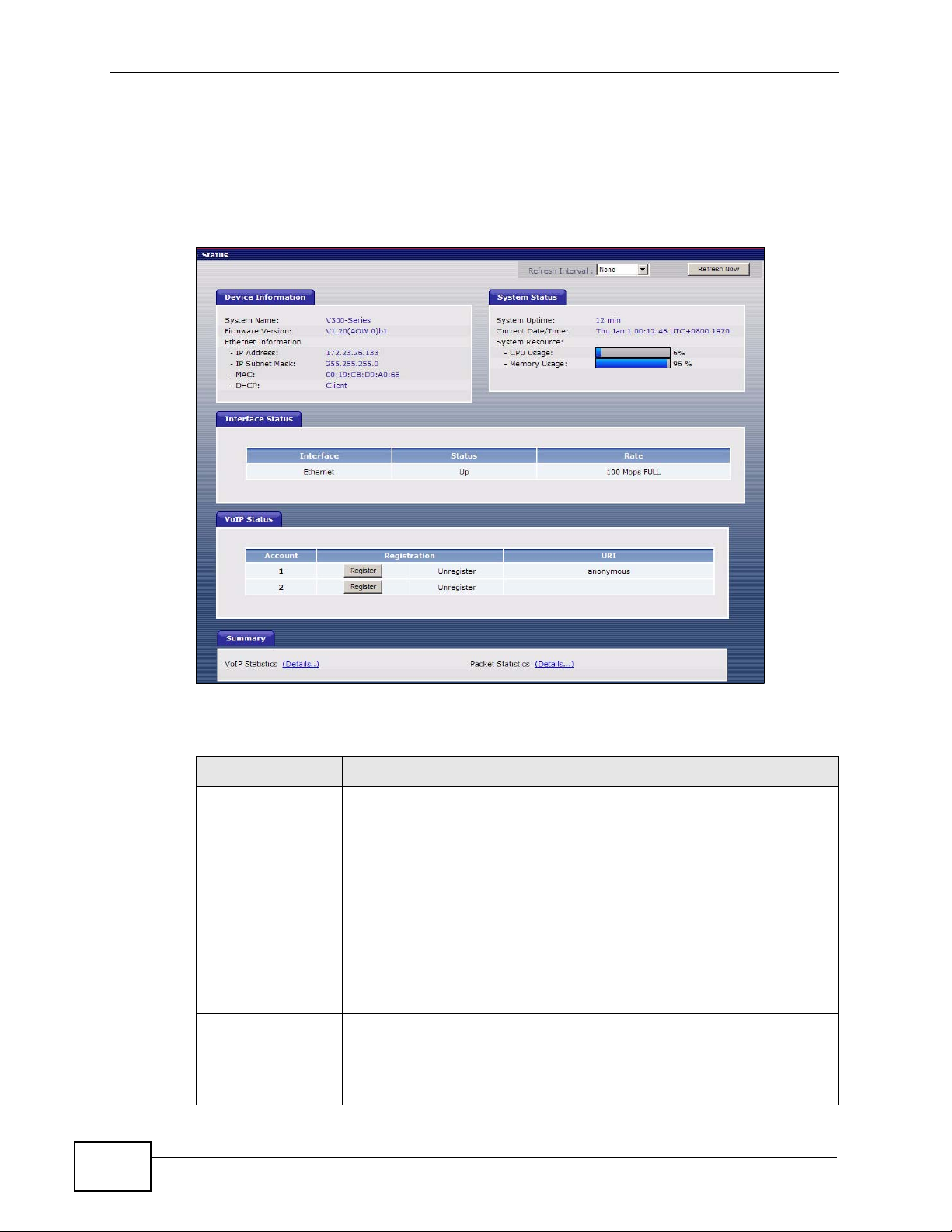
Chapter 8 The Status Screens
8.2 Status Screen
This screen displays the overall status and performance statistics of your device.
Click Status to display it.
Figure 79 Status Screen
Each field is described in the following table.
Table 20 Status Screen
LABEL DESCRIPTION
Refresh Interval Enter how often you want the V300 to update this screen.
Refresh Now Click this to update this screen immediately.
Device
Information
System Name This field displays the V300’s system name. It is used for
identification. You can change this in the Maintenance > System >
General screen’s System Name field.
Firmware
Version
IP Address This field displays the current IP address of the V300 on the LAN.
IP Subnet Mask This field displays the current subnet mask on the LAN.
MAC This is the MAC (Media Access Control) or Ethernet address unique
This field displays the current version of the firmware inside the
device. It also shows the date the firmware version was created. Y ou
can change the firmware version by uploading new firmware in
Maintenance > Tools > Firmware.
to your V300.
90
V300 Series User’s Guide
Page 91

Chapter 8 The Status Screens
Table 20 Status Screen
LABEL DESCRIPTION
DHCP This field displays what DHCP services the V300 is receiving from the
LAN. Choices are:
Client - The V300 is a DHCP client. It is receiving DHCP services.
None - The V300 is not receiving DHCP services.
You can change this in the Network > Ethernet > Internet
Connection screen.
System Status
System Uptime This field displays how long the V300 has been running since it last
started up.
Current Date/
Time
CPU Usage This field displays what percentage of the V300’s processing ability is
Memory Usage This field displays what percentage of the V300’s memory is
Interface Status
Interface This column displays each interface of the V300.
Status This field indicates whether or not the V300 is using the inte rface.
This field displays the current date and time in the V300. You can
change this in Maintenance > System > Time Setting.
currently in use. If this nears 100%, the V300 may slow down.
currently in use. If this nears 100%, the V300 may slow down. Some
memory is required just to start the V300 and to run the web
configurator. You can reduce the memory usage by deleting rules in
functions such as call forwarding, speed dial entries, and contact list
entries.
This field displays Up when the V300 is using the interface and
Down when the V300 is not using the interface.
Rate This displays the port speed and duplex setting. Ethernet port
connections can be in half-duplex or full-duplex mode. Full-duplex
refers to a device's ability to send and receive simultaneously, while
half-duplex indicates that traffic can flow in only one direction at a
time. The Ethernet port must use the same speed or duplex mode
setting as the peer Ethernet port in order to connect.
VoIP Status
Account This column displays each SIP account in the V300.
Registration This field displays the current registration status of the SIP account.
You have to register a SIP account with a SIP server to use VoIP.
If the SIP account is already registered with the SIP server,
Click Unregister to delete the SIP account’s registration in the
SIP server. This does not cancel your SIP account, but it deletes
the mapping between your SIP identity and your IP address or
domain name.
The second field displays Registered.
If the SIP account is not registered with the SIP server,
Click Register to have the V300 attempt to register the SIP
account with the SIP server.
The second field displays Unregister.
V300 Series User’s Guide
91
Page 92

Chapter 8 The Status Screens
Table 20 Status Screen
LABEL DESCRIPTION
URI This field displays the account number and service domain of the SIP
account. You can change these in VoIP > SIP > SIP Settings.
Summary
VoIP Statistics Click this link to view statistics about your VoIP usage.
Packet
Statistics
Click this link to view port status and packet specific statistics.
8.3 Packet Statistics
This screen displays read-only information here includes port status and packet
specific statistics. Also provided are "system up time" and "poll interval(s)". The
Poll Interval(s) field is configurable. To access it, open the Status screen (see
Section 8.2 on page 90), and click (Details...) next to Packet Statistics.
Figure 80 Packet Statistics
The following table describes the fields in this screen.
Table 21 Packet Statistics
LABEL DESCRIPTION
Packet Statistics
Port This column displays each interface of the V300.
Status This displays the port spe ed and duple x setting .
TxPkts This field displays the number of packets transmitted on this interface.
RxPkts This field displays the number of packets received on this interface.
Collisions This field displays the number of collisions on this port.
Tx B/s This field displays the number of bytes transmitted in the last second.
Rx B/s This field displays the number of bytes received in the last second.
92
V300 Series User’s Guide
Page 93

Table 21 Packet Statistics (continued)
LABEL DESCRIPTION
Up Time This field displays the elapsed time this interface has been connected.
System up
Time
Poll Interval(s) Type the time interval (in seconds) for the browser to refresh system
Set Interval Click this button to apply the new poll interval you entered in the Poll
Stop Click this button to halt the refreshing of the system statistics.
This is the elapsed time the system has been on.
statistics.
Interval field.
8.4 VoIP Statistics
This screen displays SIP registration information, status of calls and VoIP traffic
statistics. To access it, open the Status screen (see Section 8.2 on page 90), and
click (Details...) next to VoIP Statistics.
Chapter 8 The Status Screens
Figure 81 V oIP Statistics
V300 Series User’s Guide
93
Page 94

Chapter 8 The Status Screens
Each field is described in the following table.
Table 22 VoIP Statistics
LABEL DESCRIPTION
SIP Status
Account This column displays each SIP account in the V300.
Registration This field displays the current registration status of the SIP account. Y ou
Last
Registration
URI This field displays the account number and service domain of the SIP
Protocol This field displays the transport protocol the SIP account uses. SIP
Message
Waiting
Last
Incoming
Number
Last
Outgoing
Number
Call Statistics
Call This field displays the V300’s line number.
Peer Number This field displays the SIP number of the person on the other end of the
Status This field indicates whether the line is active or not.
can change this in the Status screen.
• Registered - The SIP account is registered with a SIP server.
• Unregister - The SIP account has failed to register with a SIP
server, or is not active.
This field displays the last time you successfully registered the SIP
account. It displays N/A if you never successfully registered this
account.
account. You can change these in VoIP > SIP > SIP Settings.
accounts always use UDP.
This field indicates whether or not there are any messages waiting for
the SIP account.
This field displays the last number that called the SIP account. It
displays N/A if no number has ever dialed the SIP account.
This field displays the last number the SIP account called. It displays N/
A if the SIP account has never dialed a number.
line, when a call is in progress.
94
• Idle - The line is not active.
• Dial - the line is active and a connection to a SIP server has been
made, but a call is not in progress.
• Dialing - the V300 is initiating a call on this line.
• Ringing - the V300 has initiated a call, and the phone at the other
end is ringing.
• Connected - a call is in progress on this line.
• Disconnect - the line is active, but the connection with the SIP
server has been terminated.
• Hold - a call on this line is on hold.
• Waiting - another line is active, and this line has an incoming call
that has not been answered.
• Transfer - a call on this line is waiting to be transferred.
• Transferred - a call on this line has been transferred to another
number, and is still ongoing.
• Incoming - an incoming call on this line is waiting to be answered.
• Busy - the V300 has tried to initiate a call, but the phone at the
other end is engaged.
V300 Series User’s Guide
Page 95

Chapter 8 The Status Screens
Table 22 VoIP Statistics
LABEL DESCRIPTION
Codec This field displays what voice codec (coder/decoder) is being used for a
current VoIP call.
Duration This field displays how long the current call has lasted.
Packets Sent This field displays the number of packets the V300 has transmitted in
the current call.
Packets Recv This field displays the number of packets the V300 has received in the
current call.
Tx Rate This field displays how quickly the V300 has transmitted packets in the
current call. The rate is the average number of bytes transmitted per
second.
Rx Rate This field displays how quickly the V300 has received packets in the
current call. The rate is the average number of bytes transmitted per
second.
Poll Interval(s) Enter how often you want the V300 to update this screen, and click Set
Interval.
Set Interval Click this to make the V300 update the screen based on the amount of
time you specified in the Poll Interval field.
Stop Click this to make the V300 stop updating the screen.
V300 Series User’s Guide
95
Page 96

Chapter 8 The Status Screens
96
V300 Series User’s Guide
Page 97

CHAPTER 9
Network Setup
9.1 Overview
This chapter discusses how to configure the V300’s network settings.
9.1.1 What You Can Do in This Chapter
•The Internet Connection screen lets you change your V300’s Internet access
settings (Section 9.2 on page 99).
•The Management Port screen lets you configure the management IP address
of the V300 (Section 9.3 on page 100).
9.1.2 What You Need to Know About Network Setup
The following terms and concepts may help you as you read through this chapter.
IP Address Assignment
Every computer on the Internet must have a unique IP address. If your networks
are isolated from the Internet (for instance, only between your two branch offices)
you can assign any IP addresses to the hosts without problems. However, the
Internet Assigned Numbers Authority (IANA) has reserved the following three
blocks of IP addresses specifically for private networks.
Table 23 Private IP Address Ranges
10.0.0.0 -
10.255.255.255
172.16.0.0 -
172.31.255.255
192.168.0.0 -
192.168.255.255
You can obt ain your IP address from the IANA, from an ISP or have it assigned by
a private network. If you belong to a small organization and your Internet access
is through an ISP, the ISP can provide you with the Internet addresses for your
local networks. On the other hand, if you are part of a much larger organization,
you should consult your network administrator for the appropriate IP addresses.
V300 Series User’s Guide
97
Page 98

Chapter 9 Network Setup
Note: Regardless of your particular situation, do not create an arbitrary IP address;
always follow the guidelines above. For more information on address
assignment, please refer to RFC 1597, Address Allocation for Private Internets
and RFC 1466, Guidelines for Management of IP Address Space.
IP Address and Subnet Mask
Similar to the way houses on a street share a common street name, computers on
a LAN share one common network number.
Where you obtain your network number depends on your particular situation. If
the ISP or your network administrator assigns you a block of registered IP
addresses, follow their instructions in selecting the IP addresses and the subnet
mask.
If the ISP did not explicitly give you an IP network number, then most likely you
have a single user account and the ISP will assign you a dynamic IP address when
the connection is established. The Internet Assigned Number Authority (IANA)
reserved this block of addresses specifically for private use; please do not use any
other number unless you are told otherwise. Let's say you select 192.168.1.0 as
the network number; which covers 254 individual addresses, from 192.168.1.1 to
192.168.1.254 (zero and 255 are reserved). In other words, the first three
numbers specify the network number while the last number identifies an individual
computer on that network.
Once you have decided on the network number , pick an IP address that is easy to
remember, for instance, 192.168.1.2, for your device, but make sure that no other
device on your network is using that IP address.
The subnet mask specifies the network number portion of an IP address. Your
device will compute the subnet mask automatically based on the IP address that
you entered. You don't need to change the subnet mask computed by the device
unless you are instructed to do otherwise.
PPPoE Encapsulation
The V300 supports PPPoE (Point-to-P oint Protocol over Ethernet). PPP oE is an IETF
standard (RFC 2516) specifying how a personal computer (PC) interacts with a
broadband modem (DSL, cable, wireless, etc.) connection.
For the service provider, PPPoE offers an access and authentication method that
works with existing access control systems (for example Radius).
One of the benefits of PPPoE is the ability to let you access one of multiple network
services, a function known as dynamic servic e selection. This enables the service
provider to easily create and offer new IP services for individuals.
98
V300 Series User’s Guide
Page 99

Operationally, PPP oE sav es significant effort for both you and the ISP or carrier, as
it requires no specific configuration of the broadband modem at the customer site .
By implementing PPPoE directly on the V300 (rather than individual computers),
the computers on the LAN do not need PPPoE software installed, since the V300
does that part of the task. Furthermore, with NAT, all of the LANs’ computers will
have access.
9.2 Internet Connection
Use this screen to change your V300’s Internet access settings. Click Network >
Internet Connection.
Figure 82 Network > Internet Connection
Chapter 9 Network Setup
The following table describes the labels in this screen.
Table 24 Network > Internet Connection
LABEL DESCRIPTION
Ethernet TCP/IP Settings
Get
automatically
from DHCP
Use Fixed IP
Address
IP Address Enter your WAN IP address in this field if you selected Use Fixed IP
IP Subnet
Mask
Gateway IP
Address
V300 Series User’s Guide
Select this option if your ISP did not give you an IP address.
Select this option If your ISP assigned a fixed IP address. Enter the
address information in the following fields.
Address.
Enter the IP Subnet Mask in this field.
Enter a Gateway IP Address (if your ISP gave you one) in this field.
99
Page 100

Chapter 9 Network Setup
Table 24 Network > Internet Connection
LABEL DESCRIPTION
Primary DNS
Secondary
DNS
PPPoE
Use PPPoE
Client
PPPoE User
Name
Password Type the password associated with the user name above.
Apply Click this to save your changes.
Reset Click this to reload the previous configuration for this screen.
Enter the DNS (Domain Name Service) servers, if provided by your
ISP.
Select this if your V300 is a PPPoE client.
Type the user name given to you by your ISP.
9.3 Management Port
Use this screen to configure the management IP address of the V300. Y ou can use
this IP address to connect to the V300 even when its WAN IP address is in a
different subnet. Your computer must be in the same subnet as the management
IP address to use it.
Click Network > Ethernet > Mgnt Port. The following screen displays.
Figure 83 Network > Mgnt Port
The following table describes the labels in this screen.
Table 25 Network > Mgnt Port
LABEL DESCRIPTION
Management IP Address
IP Address Enter the new management IP address you want the V300 to use.
Apply Click this to save your changes.
Reset Click this to reload the previous configuration for this screen.
100
V300 Series User’s Guide
 Loading...