


Prestige 650M
ADSL Bridge
User's Guide
Version 3.40
March 2003

Prestige 650M ADSL Bridge
Copyright
Copyright © 2003 by ZyXEL Communications Corporation.
The contents of this publication may not be reproduced in any part or as a whole, transcribed, stored in a
retrieval system, translated into any language, or transmitted in any form or by any means, electronic,
mechanical, magnetic, optical, chemical, photocopying, manual, or otherwise, without the prior written
permission of ZyXEL Communications Corporation.
Published by ZyXEL Communications Corporation. All rights reserved.
Disclaimer
ZyXEL does not assume any liability arising out of the application or use of any products, or software
described herein. Neither does it convey any license under its patent rights nor the patent rights of others.
ZyXEL further reserves the right to make changes in any products described herein without notice. This
publication is subject to change without notice.
Trademarks
ZyNOS (ZyXEL Network Operating System) is a registered trademark of ZyXEL Communications, Inc.
Other trademarks mentioned in this publication are used for identification purposes only and may be
properties of their respective owners.
ii Copyright

Prestige 650M ADSL Bridge
Federal Communications Commission
(FCC) Interference Statement
This device complies with Part 15 of FCC rules. Operation is subject to the following two conditions:
• This device may not cause harmful interference.
• This device must accept any interference received, including interference that may cause undesired
operations.
This equipment has been tested and found to comply with the limits for a Class B digital device pursuant to
Part 15 of the FCC Rules. These limits are designed to provide reasonable protection against harmful
interference in a commercial environment. This equipment generates, uses, and can radiate radio frequency
energy, and if not installed and used in accordance with the instructions, may cause harmful interference to
radio communications.
If this equipment does cause harmful interference to radio/television reception, which can be determined by
turning the equipment off and on, the user is encouraged to try to correct the interference by one or more of
the following measures:
1. Reorient or relocate the receiving antenna.
2. Increase the separation between the equipment and the receiver.
3. Connect the equipment into an outlet on a circuit different from that to which the receiver is connected.
4. Consult the dealer or an experienced radio/TV technician for help.
Notice 1
Changes or modifications not expressly approved by the party responsible for compliance could void the
user's authority to operate the equipment.
Certifications
Refer to the product page at www.zyxel.com.
FCC Statement iii

Prestige 650M ADSL Bridge
ZyXEL Limited Warranty
ZyXEL warrants to the original end user (purchaser) that this product is free from any defects in materials
or workmanship for a period of up to two years from the date of purchase. During the warranty period, and
upon proof of purchase, should the product have indications of failure due to faulty workmanship and/or
materials, ZyXEL will, at its discretion, repair or replace the defective products or components without
charge for either parts or labor, and to whatever extent it shall deem necessary to restore the product or
components to proper operating condition. Any replacement will consist of a new or re-manufactured
functionally equivalent product of equal value, and will be solely at the discretion of ZyXEL. This warranty
shall not apply if the product is modified, misused, tampered with, damaged by an act of God, or subjected
to abnormal working conditions.
Note
Repair or replacement, as provided under this warranty, is the exclusive remedy of the purchaser. This
warranty is in lieu of all other warranties, express or implied, including any implied warranty of
merchantability or fitness for a particular use or purpose. ZyXEL shall in no event be held liable for indirect
or consequential damages of any kind of character to the purchaser.
To obtain the services of this warranty, contact ZyXEL's Service Center for your Return Material
Authorization number (RMA). Products must be returned Postage Prepaid. It is recommended that the unit
be insured when shipped. Any returned products without proof of purchase or those with an out-dated
warranty will be repaired or replaced (at the discretion of ZyXEL) and the customer will be billed for parts
and labor. All repaired or replaced products will be shipped by ZyXEL to the corresponding return address,
Postage Paid. This warranty gives you specific legal rights, and you may also have other rights that vary
from country to country.
iv ZyXEL Warranty
Prestige 650M ADSL Bridge
Customer Support
Please have the following information ready when you contact customer support.
• Product model and serial number.
• Information in Menu 24.2.1 – System Information.
• Warranty Information.
• Date that you received your device.
• Brief description of the problem and the steps you took to solve it.
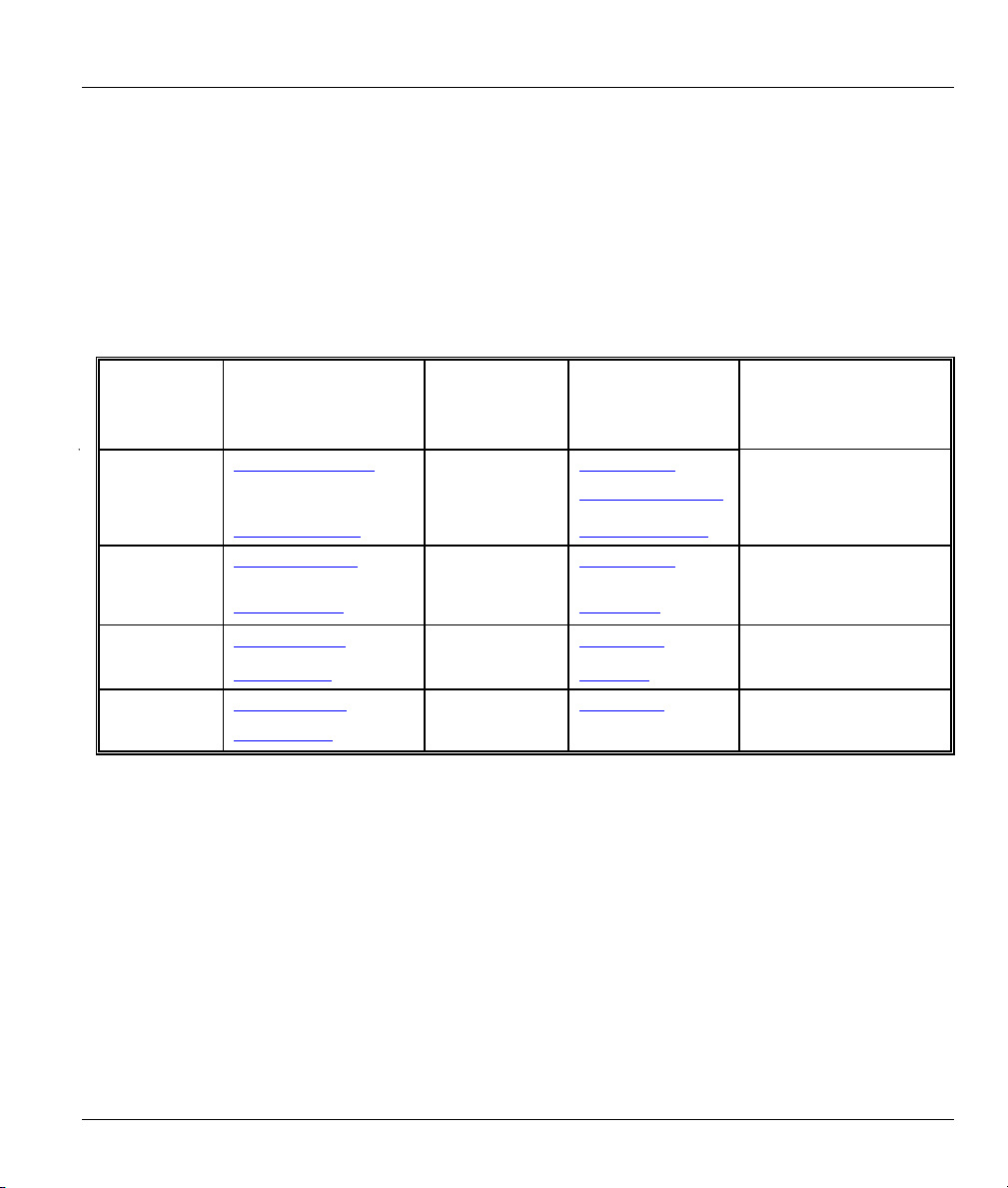
METHOD
LOCATION
WORLDWIDE
AMERICA
support@zyxel.com.tw
sales@zyxel.com.tw
support@zyxel.com +1-714-632-0882
sales@zyxel.com
support@zyxel.dk +45-3955-0700 www.zyxel.dk SCANDINAVIA
sales@zyxel.dk
support@zyxel.de +49-2405-6909-0 www.zyxel.de GERMANY
sales@zyxel.de
E-MAIL
SUPPORT/SALES
+886-3-578-2439 ftp.europe.zyxel.com
+1-714-632-0858 ftp.zyxel.com
+45-3955-0707 ftp.zyxel.dk
+49-2405-6909-99
TELEPHONE/FAX WEB SITE/ FTP SITE REGULAR MAIL
+886-3-578-3942 www.zyxel.com
www.europe.zyxel.com
www.zyxel.com NORTH
800-255-4101
ZyXEL Communications
Corp., 6 Innovation Road II,
Science-Based Industrial Park,
Hsinchu 300, Taiwan
ZyXEL Communications Inc.,
1650 Miraloma Avenue,
Placentia, CA 92870, U.S.A.
ZyXEL Communications A/S,
Columbusvej 5, 2860
Soeborg, Denmark
ZyXEL Deutschland GmbH.
Adenauerstr. 20/A2 D-52146
Wuerselen, Germany
Customer Support v


Prestige 650M ADSL Bridge
Table of Contents
Copyright .........................................................................................................................................ii
Federal Communications Commission (FCC) Interference Statement ..........................................iii
ZyXEL Limited Warranty.................................................................................................................iv
Customer Support .......................................................................................................................... v
List of Figures ................................................................................................................................. x
List of Tables..................................................................................................................................xii
Preface .........................................................................................................................................xiii
What is DSL?.................................................................................................................................xv
Chapter 1 Getting To Know Your Prestige................................................................................................. 1-1
1.1 Prestige 650M ADSL Bridge .............................................................................................1-1
1.2 Features of the Prestige.................................................................................................... 1-1
1.3 Applications for the Prestige .............................................................................................1-3
Chapter 2 Hardware Installation and Initial Setup.................................................................................. 2-1
2.1 Front Panel LEDs of the Prestige .....................................................................................2-1
2.2 Rear Panel of the Prestige................................................................................................2-2
2.3 Connecting an ISDN Splitter .............................................................................................2-4
2.4 Turning On Your Prestige..................................................................................................2-5
Chapter 3 Initial Setup ................................................................................................................................ 3-1
3.2 Prestige SMT Overview ....................................................................................................3-1
3.3 Navigating the SMT Interface ...........................................................................................3-2
3.4 Changing the System Password.......................................................................................3-4
3.5 SMT Menu 1: General Setup ............................................................................................ 3-6
3.6 LANs and WANs ...............................................................................................................3-6
3.7 SMT Menu 3: TCP/IP LAN Setup...................................................................................... 3-8
Chapter 4 Internet Access ........................................................................................................................... 4-1
4.1 Introduction .......................................................................................................................4-1
4.2 VPI and VCI ......................................................................................................................4-1
Table of Contents vii

Prestige 650M ADSL Bridge
4.3 Multiplexing .......................................................................................................................4-2
4.4 Encapsulation....................................................................................................................4-2
4.5 Internet Access Configuration ...........................................................................................4-4
Chapter 5 Remote Node Configuration ......................................................................................................5-1
5.1 Remote Node Setup..........................................................................................................5-1
Chapter 6 Filter Set Configuration .............................................................................................................6-1
6.1 About Filtering ...................................................................................................................6-1
6.2 Configuring a Filter Set......................................................................................................6-3
6.3 Generic Filter Rule ............................................................................................................6-4
6.4 Filter Configuration Example.............................................................................................6-6
6.5 Applying Filters..................................................................................................................6-7
Chapter 7 System Information and Diagnosis............................................................................................7-1
7.1 Introduction........................................................................................................................7-1
7.2 System Status ...................................................................................................................7-1
7.3 System Information and Console Port Speed...................................................................7-3
7.4 Diagnostic..........................................................................................................................7-5
7.5 Command Interpreter Mode ..............................................................................................7-6
Chapter 8 Firmware and Configuration File Maintenance ......................................................................8-1
8.1 Identifying Your Product ....................................................................................................8-1
8.2 Filename Conventions.......................................................................................................8-1
8.3 Backup Configuration........................................................................................................8-2
8.4 Restore Configuration .......................................................................................................8-6
8.5 Uploading Firmware and Configuration Files....................................................................8-8
Chapter 9 Troubleshooting...........................................................................................................................9-1
9.1 Problems Starting the Prestige..........................................................................................9-1
9.2 Power Problems ................................................................................................................9-1
9.3 Problems Connecting to the LAN......................................................................................9-2
9.4 Problems Connecting with the WAN or Remote Node/ISP...............................................9-2
9.5 Problems Accessing the SMT Menu .................................................................................9-3
viii Table of Contents

Prestige 650M ADSL Bridge
9.6 Problems Accessing the Internet ......................................................................................9-3
Appendix A Power Adapter Specifications....................................................................................................A
Appendix B Virtual Circuit Topology............................................................................................................ C
Appendix C Setting up Your Computer’s IP Address .................................................................................. D
Index.................................................................................................................................................................O
Table of Contents ix

Prestige 650M ADSL Bridge
List of Figures
Figure 1-1 Internet Access Application...........................................................................................................1-3
Figure 1-2 LAN-to-LAN Application .............................................................................................................1-4
Figure 2-1 Prestige Front Panel ......................................................................................................................2-1
Figure 2-2 Prestige Rear Panel and Connections............................................................................................2-2
Figure 2-3 ISDN Splitter Installation..............................................................................................................2-4
Figure 3-1 Password Screen ...........................................................................................................................3-1
Figure 3-2 Prestige SMT Menu Overview......................................................................................................3-2
Figure 3-3 SMT Main Menu...........................................................................................................................3-4
Figure 3-4 Menu 23 – System Password ........................................................................................................3-5
Figure 3-5 Menu 1–General Setup..................................................................................................................3-6
Figure 3-6 LAN & WAN IPs ..........................................................................................................................3-7
Figure 3-7 Menu 3.2 – TCP/IP and DHCP Ethernet Setup.............................................................................3-8
Figure 4-1 Example of Traffic Shaping ..........................................................................................................4-4
Figure 4-2 Internet Access Setup ....................................................................................................................4-4
Figure 5-1 Menu 11–Remote Node Setup ......................................................................................................5-1
Figure 5-2 Menu 11.1-Remote Node Profile ..................................................................................................5-2
Figure 6-1 Filter Rule Process ........................................................................................................................6-2
Figure 6-2 Menu 21–Filter Set Configuration ................................................................................................6-3
Figure 6-3 Menu 21.1–Filter Rules Summary ................................................................................................6-3
Figure 6-4 Menu 21.5.1–Generic Filter Rule..................................................................................................6-5
Figure 6-5 Sample Filter Rules Summary – Menu 21.3 .................................................................................6-7
Figure 6-6 Filtering Remote Node Traffic ......................................................................................................6-8
Figure 7-1 Menu 24 – System Maintenance ...................................................................................................7-1
Figure 7-2 Menu 24.1 – System Maintenance – Status...................................................................................7-2
Figure 7-3 Menu 24.2 – System Information and Console Port Speed...........................................................7-3
Figure 7-4 Menu 24.2.1 – System Maintenance – Information ......................................................................7-4
x List of Figures

Prestige 650M ADSL Bridge
Figure 7-5 Menu 24.2.2 – System Maintenance – Change Console Port Speed............................................ 7-5
Figure 7-6 Menu 24.4 – System Maintenance – Diagnostic ..........................................................................7-6
Figure 7-7 Command Mode in Menu 24........................................................................................................ 7-7
Figure 7-8 Valid Commands .......................................................................................................................... 7-7
Figure 8-1 Telnet in Menu 24.5...................................................................................................................... 8-3
Figure 8-2 FTP Session Example................................................................................................................... 8-4
Figure 8-3 Telnet into Menu 24.6................................................................................................................... 8-7
Figure 8-4 Restore Using FTP Session Example ........................................................................................... 8-7
Figure 8-5 Telnet Into Menu 24.7.1 - Upload System Firmware ................................................................... 8-8
Figure 8-6 Telnet Into Menu 24.7.2 - System Maintenance........................................................................... 8-9
Figure 8-7 FTP Session Example of Firmware File Upload ........................................................................ 8-10
List of Figures xi

Prestige 650M ADSL Bridge
List of Tables
Table 1 P650M Models ................................................................................................................................ xiii
Table 2-1 Front Panel LED Description....................................................................................................... 2-1
Table 3-1 Main Menu Commands................................................................................................................ 3-3
Table 3-2 Main Menu Summary .................................................................................................................. 3-4
Table 3-3 General Setup Menu Fields.......................................................................................................... 3-6
Table 3-4 TCP/IP Ethernet Setup Menu Fields ............................................................................................3-8
Table 4-1 Internet Account Information....................................................................................................... 4-1
Table 4-2 Internet Access Setup Menu Fields.............................................................................................. 4-5
Table 5-1 Remote Node Profile Menu Fields............................................................................................... 5-2
Table 6-1 Abbreviations Used in the Filter Rules Summary Menu.............................................................. 6-4
Table 6-2 Rule Abbreviations Used ............................................................................................................. 6-4
Table 6-3 Menu 21.5.1 – Generic Filter Rule Fields .................................................................................... 6-5
Table 6-4 Filter Set Types ............................................................................................................................ 6-7
Table 7-1 System Maintenance – Status Menu Fields..................................................................................7-2
Table 7-2 Fields in System Maintenance .....................................................................................................7-4
Table 7-3 System Maintenance Menu – Diagnostic..................................................................................... 7-6
Table 8-1 Filename Conventions.................................................................................................................. 8-2
Table 8-2 General Commands for GUI-based FTP Clients.......................................................................... 8-4
Table 8-3 General Commands for GUI-based TFTP Clients ....................................................................... 8-5
Table 9-1 Problems Starting the Prestige ..................................................................................................... 9-1
Table 9-2 Problems With the Power Source................................................................................................. 9-1
Table 9-3 Problems Connecting with the LAN............................................................................................ 9-2
Table 9-4 Problems Connecting with the WAN or Remote Node/ISP ......................................................... 9-2
Table 9-5 Problems Accessing SMT Menus ................................................................................................ 9-3
Table 9-6 Problems Accessing the Internet .................................................................................................. 9-3
xii List of Tables

Prestige 650M ADSL Bridge
Preface
Congratulations on your purchase of the Prestige 650M Ethernet Bridge.
There are three types of P650M bridges. Please refer to the label under your device to see which type you
have. The key hardware difference is the DSL connector. The analog model uses an RJ-11 connector while
the digital models use RJ-45 connectors. The firmware features of all three models are identical.
Table 1 P650M Models
MODEL TYPE DESCRIPTION
P650M-31 Analog model for ADSL over POTS (Plain Old telephone System). RJ-11 connector
P650M-33 Analog model for ADSL over ISDN. RJ-45 connector.
P650M-37 Analog model for ADSL over ISDN in Germany. RJ-45 connector.
The Prestige 650M is an ADSL bridge used for Internet/LAN access via POTS or ISDN line. The Prestige
can run maximum upstream transmission rates of up to 832Kbps and maximum downstream transmission
rates of 8Mbps. The actual rate depends on the copper category of your phone line and distance from the
central office. See the What is DSL section for more background information on DSL and ADSL.
The Prestige’s 10/100M auto-negotiating LAN interface enables fast data transfer of either 10Mbps or
100Mbps in either half-duplex or full-duplex mode depending on your Ethernet network.
Your Prestige is easy to install and configure. All functions of the Prestige are software configurable via the
SMT (System Management Terminal) using Telnet.
Register your Prestige online at www.zyxel.com
and information.
for free future product updates
About This User's Guide
This User's Guide covers all P650M models, their operation and shows you how to get the best out of the
multiple advanced features of your DSL Internet access modem using SMT menus. It is designed to guide
you through the correct configuration of your Prestige for various applications.
Related Documentation
Support Disk
Refer to the included CD for support documents.
Read Me First
Preface xiii

Prestige 650M ADSL Bridge
Our Read Me First is designed to help you get up and running right away. It contains a detailed
easy-to-follow connection diagram, default settings, handy checklists and information on setting
up your network and configuring for Internet access.
ZyXEL Glossary and Web Site
Please refer to www.zyxel.com
documentation.
for an online glossary of networking terms and additional support
Syntax Conventions
• “Type” means for you to type one or more characters and press the carriage return. “Select” or
“Choose” means for you to use one from the predefined choices.
• The SMT menu titles and labels are in Bold Times New Roman font. Predefined field choices are in
Bold Arial font. Command and arrow keys are enclosed in square brackets. [ENTER] means the
Enter, or carriage return key; [ESC] means the Escape key and [SPACE BAR] means the Space Bar.
• For brevity’s sake, we may use “e.g.,” as shorthand for “for instance”, and “i.e.,” for “that is” or “in
other words” in this manual.
• The Prestige 650M ADSL Bridge may be referred to as the Prestige in this User’s Guide when
referring to all three models and to P650M-31, P650M-33 or P650M-37 when referring to the specific
model.
The following section offers some background information on DSL. Skip to
Chapter 1 if you wish to begin working with your modem right away.
xiv Preface

Prestige 650M ADSL Bridge
What is DSL?
DSL (Digital Subscriber Line) enhances the data capacity of the existing twisted-pair wire that runs
between the local telephone company switching offices and most homes and offices. While the wire itself
can handle higher frequencies, the telephone switching equipment is designed to cut off signals above 4,000
Hz to filter noise off the voice line, but now everybody is searching for ways to get more bandwidth to
improve access to the Web - hence DSL technologies.
There are actually seven types of DSL service, ranging in speeds from 16 Kbits/sec to 52 Mbits/sec. The
services are either symmetrical (traffic flows at the same speed in both directions), or asymmetrical (the
downstream capacity is higher than the upstream capacity). Asymmetrical services (ADSL) are suitable for
Internet users because more information is usually downloaded than uploaded. For example, a simple
button click in a web browser can start an extended download that includes graphics and text.
As data rates increase, the carrying distance decreases. That means that users who are beyond a certain
distance from the telephone company’s central office may not be able to obtain the higher speeds.
A DSL connection is a point-to-point dedicated circuit, meaning that the link is always up and there is no
dialing required.
What is ADSL?
It is an asymmetrical technology, meaning that the downstream data rate is much higher than the upstream
data rate. As mentioned, this works well for a typical Internet session in which more information is
downloaded, for example, from Web servers, than is uploaded. ADSL operates in a frequency range that is
above the frequency range of voice services, so the two systems can operate over the same cable.
What is DSL? xv


Prestige 650M ADSL Bridge
Chapter 1
Getting To Know Your Prestige
This chapter describes the key features and applications of your Prestige.
1.1 Prestige 650M ADSL Bridge
Your Prestige integrates a high-speed 10/100Mbps auto-negotiating LAN interface and one high-speed DSL
port into a single package. The Prestige is ideal for high-speed Internet browsing and making LAN-to-LAN
connections to remote networks.
1.2 Features of the Prestige
Your Prestige is packed with a number of features that give it the flexibility to provide a complete
networking solution for almost any user.
High Speed Internet Access
Your Prestige supports downstream transmission rates of up to 8Mbps and upstream transmission rates of
832 Kbps. Your Prestige also supports rate management.
10/100M Auto-negotiation Ethernet/Fast Ethernet Interface
This auto-negotiation feature allows the Prestige to detect the speed of incoming transmissions and adjust
appropriately without manual intervention. It allows data transfer of either 10 Mbps or 100 Mbps in either
half-duplex or full-duplex mode depending on your Ethernet network.
Multiple PVC (Permanent Virtual Circuits) Support
Your Prestige supports up to 8 PVCs.
DSL Transmission Rate Standards
♦ Full-Rate (ANSI T1.413, Issue 2; G.dmt (G.992.1) with line rate support of up to 8 Mbps downstream
and 832 Kbps upstream.
♦ Supports Multi-Mode standard (ITU G.992.1, G.994.1, G.997.1).
♦ TCP/IP (Transmission Control Protocol/Internet Protocol) network layer protocol.
♦ ATM Forum UNI 3.1/4.0 PVC.
Getting To Know Your Prestige 1-1

Prestige 650M ADSL Bridge
♦ PPP over AAL5 (RFC 2364).
♦ EOC specified in ITU-T G.992.1
♦ Dying Gasp
♦ IP Bridge Mode
• Protocol Support
♦ PPP (Point-to-Point Protocol) (RFC 1144, 1332, 1334, 1570, 1661, 1994, 1998 (plus amendments))
♦ Multiprotocol Encapsulation over ATM (MpoA) (RFC 1483/2684)
♦ Transparent bridging for unsupported network layer protocols
Networking Compatibility
Your Prestige is compatible with the major DSL DSLAM (Digital Subscriber Line Access Multiplexer)
providers, making configuration as simple as possible for you.
Multiplexing
The Prestige Series supports VC-based and LLC-based multiplexing.
Encapsulation
The Prestige supports PPPoA (RFC 2364 - PPP over ATM Adaptation Layer 5) and RFC 1483
encapsulation over ATM.
Network Management
♦ Menu driven SMT (System Management Terminal) management
♦ CLI (Command Line Interpreter)
♦ Remote SMT session via Telnet
♦ Local SMT session via Telnet
♦ Built-in Diagnostic Tools
♦ Syslog
♦ Telnet Support (Password-protected telnet access to internal configuration manager)
♦ TFTP/FTP server, firmware upgrade and configuration backup/support supported
♦ Supports OAM F4/F5 loop-back, AIS and RDI OAM cells
1-2 Getting To Know Your Prestige
Prestige 650M ADSL Bridge
• Diagnostics Capabilities
The Prestige can perform self-diagnostic tests. These tests check the integrity of the following circuitry:
FLASH memory
DSL circuitry
RAM
LAN port
Filters
The Prestige's packet filtering functions allows added network security and management.
Ease of Installation
Your Prestige is designed for quick, intuitive and easy installation.
Housing
Your Prestige's all new compact and ventilated housing minimizes space requirements making it easy to
position anywhere in your busy office. The Prestige is easy to mount on your wall.
1.3 Applications for the Prestige
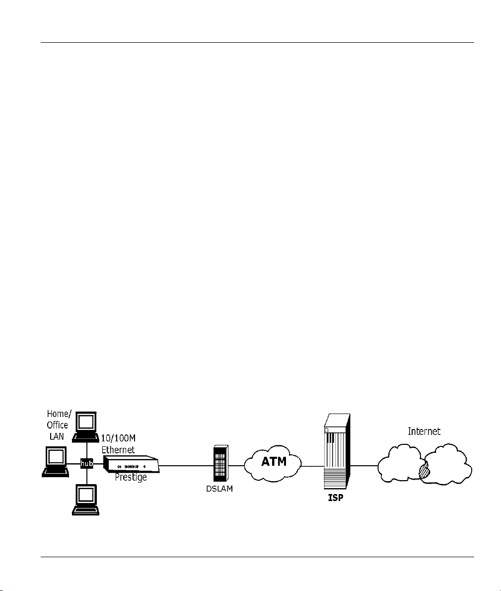
1.3.1 Internet Access
The Prestige is the ideal high-speed Internet access solution. Your Prestige supports the TCP/IP protocol,
which the Internet uses exclusively. It is compatible with all major DSL DSLAM (Digital Subscriber Line
Access Multiplexer) providers. A DSLAM is a rack of DSL line cards with data multiplexed into a
backbone network interface/connection (for example, T1, OC3, DS3, ATM or Frame Relay). Think of it as
the equivalent of a modem rack for DSL. A typical Internet Access application is shown below.
Figure 1-1 Internet Access Application
Getting To Know Your Prestige 1-3
Prestige 650M ADSL Bridge
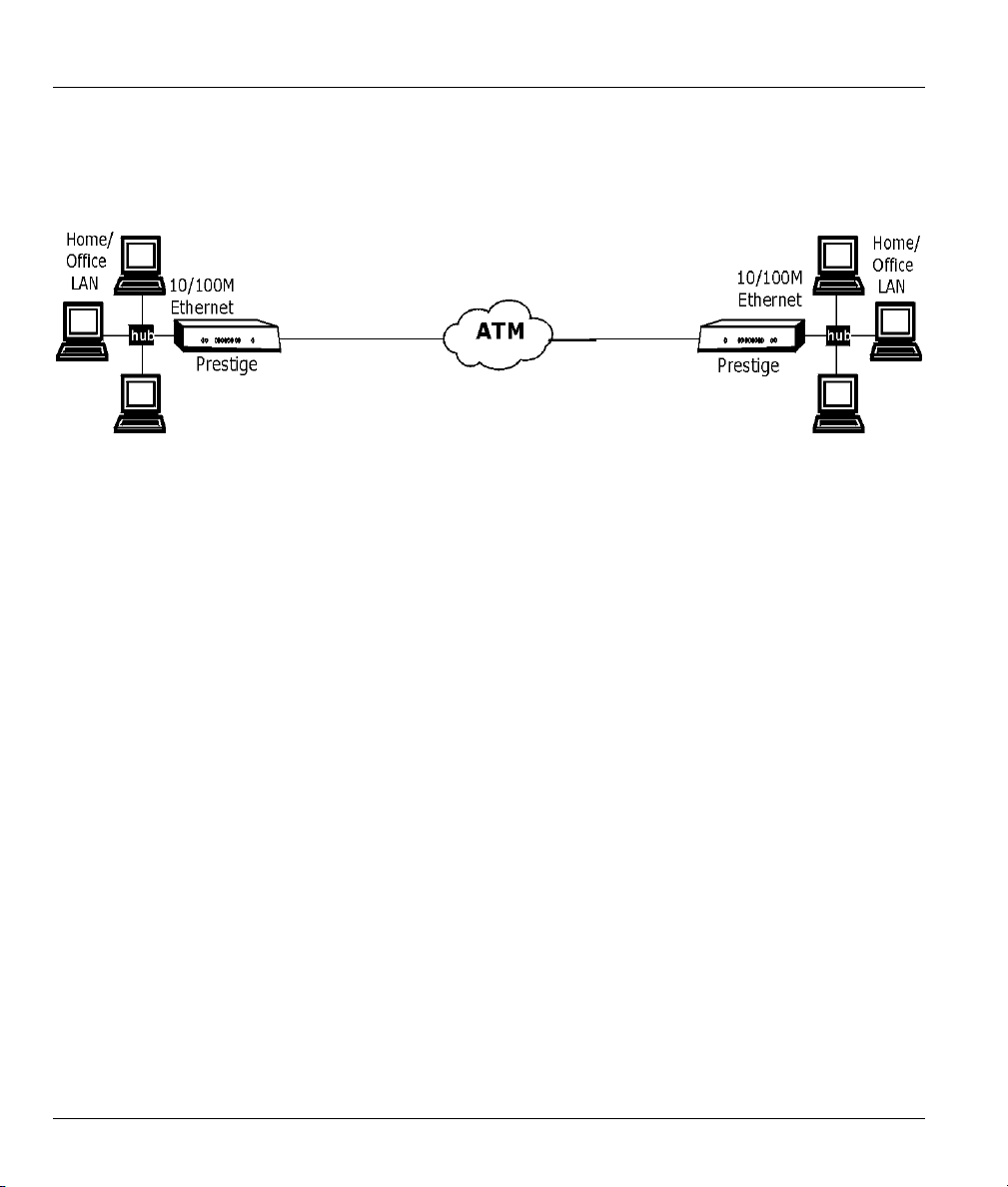
1.3.2 LAN to LAN Application
You can use the Prestige to connect two geographically dispersed networks over the DSL line. A typical
LAN-to-LAN application for your Prestige is shown as follows.
Figure 1-2 LAN-to-LAN Application
1-4 Getting To Know Your Prestige
Prestige 650M ADSL Bridge
Chapter 2
Hardware Installation and Initial Setup
This chapter describes the physical features of the Prestige and how to make cable connections.
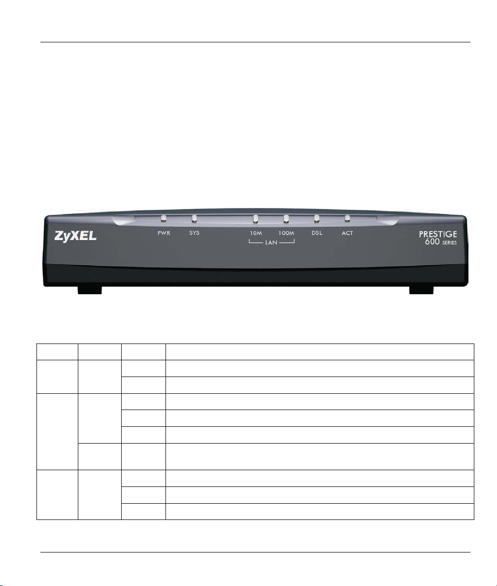
2.1 Front Panel LEDs of the Prestige
The LEDs on the front panel indicate the operational status of your Prestige
Figure 2-1 Prestige Front Panel
Table 2-1 Front Panel LED Description
LED COLOR
SYS
LAN
10M
Hardware Installation 2-1
Green
Red On Prestige power is low and consequently may be disconnected from the DSL
Green
STATUS
On The Prestige is receiving power. PWR Green
Off The Prestige is not receiving power.
On The Prestige is functioning properly.
Blinking The Prestige is rebooting.
Off The Prestige is not ready or has malfunctioned.
line.
On The Prestige has a successful 10Mb Ethernet connection.
Blinking The Prestige is sending/receiving data.
Off The Prestige does not have 10Mb Ethernet connection.
DESCRIPTION
Prestige 650M ADSL Bridge
Table 2-1 Front Panel LED Description
LED COLOR
LAN
100M
DSL Green
Orange
STATUS
On The Prestige has a successful 100Mb Ethernet connection.
Blinking The Prestige is sending/receiving data.
Off The Prestige does not have 100Mb Ethernet connection.
On The Prestige is linked successfully to a DSLAM.
Blinking The Prestige is synchronizing.
Off The DSL link is down.
Blinking The Prestige is sending/receiving data. Act Green
Off The Prestige is not sending/receiving data.
DESCRIPTION
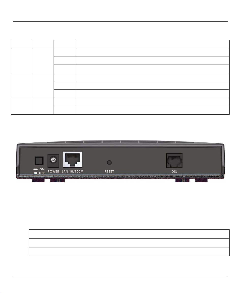
2.2 Rear Panel of the Prestige
The following figure shows the rear panel and connections of your Prestige.
Figure 2-2 Prestige Rear Panel and Connections
2.2.1 DSL Port
There are three types of P650M bridges. Please refer to the label under your device to see which type you
have. The key hardware difference is the DSL connector. The analog model uses an RJ-11 connector while
the digital models use RJ-45 connectors.
P650M-31 RJ-11 connector
P650M-33 RJ-45 connector.
P650M-37 RJ-45 connector.
2-2 Hardware Installation

Prestige 650M ADSL Bridge
Connect the Prestige to the wall jack using the included DSL cable. For the P650M-33 and P650M-37
models, connect an ISDN splitter between the wall jack and your telephone(s) and computer(s).
2.2.2 LAN 10/100M Port
Ethernet 10Base-T/100Base-T networks use Shielded Twisted Pair (STP) cable. This port is auto-sensing
which means Use a crossover cable or a straight-through Ethernet cable to connect your Prestige to a
computer or an external hub. If the Prestige is connected directly to a hub, connect one end of the straightthrough cable from the hub to the NIC on the computer.
When the Prestige is on and properly connected to a computer or a hub, the
corresponding LAN LED on the front panel turns on.
2.2.3 Power Port
Connect the power adapter to the port labeled POWER on the rear panel of your Prestige.
To avoid damage to the Prestige, make sure you use the correct power adapter.
Refer to the Power Adapter Specification Appendix for this information.
2.2.4 Reset Button
If you have forgotten your password or cannot access the Prestige you will need to use the RESET button
on the rear panel of the Prestige to reload the factory-default configuration file. Uploading the configuration
file replaces the current configuration file with the default configuration file and deletes all previous
Prestige configurations. The following are the factory defaults for the Prestige.
• IP address: 192.168.1.1
• Password: 1234
2.2.5 Procedure to Use the RESET Button
Step 1. Use a pen or pointed object to press the RESET button for 5-10 seconds or until the SYS LED
flashes and then release it.
Step 2. If the SYS LED turns steady on and the LAN LED flashes within 30 seconds, the factory defaults
have been restored and the Prestige restarts. Otherwise, go to step 3.
Step 3. Turn the Prestige off.
Step 4. While pressing the RESET button, turn the Prestige on.
Hardware Installation 2-3
Prestige 650M ADSL Bridge
Step 5. Continue to hold the RESET button for about 30 seconds. The Prestige restarts.
Step 6. Release the RESET button and wait for the Prestige to finish restarting.
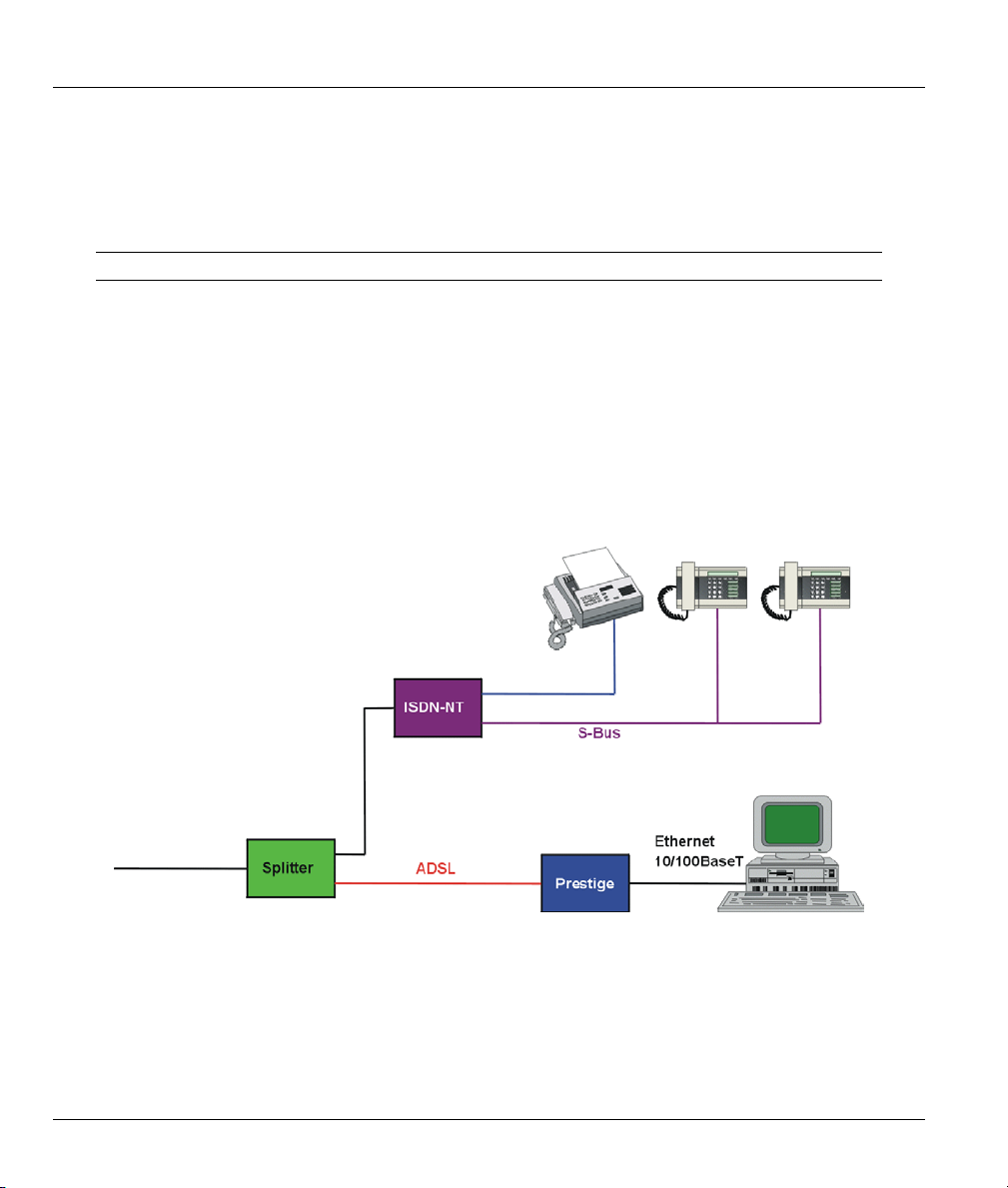
2.3 Connecting an ISDN Splitter
This section is relevant for P650M-33 and P650M-37 models only!
This device keeps the ISDN and DSL signals separated, giving them the capability to provide simultaneous
Internet access and ISDN service on the same line. Splitters also eliminate the destructive interference
conditions caused by telephone sets. The purchase of an ISDN splitter is optional.
Noise generated from a telephone in the same frequency range as the DSL signal, can disrupt the DSL
signal. In addition the impedance of a telephone when off-hook may be so low that it shunts the strength of
the DSL signal. When an ISDN splitter is installed at the entry point, where the line comes into the home, it
will filter the ISDN signals before combining the DSL and ISDN signals transmitted and received. The
issues of noise and impedance are eliminated with a single ISDN splitter installation.
An ISDN splitter is easy to install as shown in the following figure.
Figure 2-3 ISDN Splitter Installation
2-4 Hardware Installation

Prestige 650M ADSL Bridge
2.4 Turning On Your Prestige
At this point, you should have connected the DSL, LAN and Power ports to the appropriate devices. Make
sure the power adapter is plugged into an appropriate power source.
Press the power switch in. The Power LED turns on. The SYS LED blinks and turns steady on. The SYS
LED turns red if power is too low. The LAN and DSL LEDs turn on, if they are properly connected.
Hardware Installation 2-5


Prestige 650M ADSL Bridge
Chapter 3
Initial Setup
This chapter introduces the SMT and shows you how to configure SMT menus 1 and 3.
Configure your Prestige using the SMT (System Management Terminal) via LAN or WAN using Telnet.
3.1.1 Connect to Your Prestige Using Telnet
The following procedure details how to telnet into your Prestige.
Step 1. In Windows, click Start (usually in the bottom left corner), Run and then type “telnet
192.168.1.1” (the default IP address) and click OK.
Step 2. Enter 1234 in the Password field.
After entering the password you will see the main menu.
3.1.2 Entering Password
When you turn on your Prestige, it performs several internal tests as well as line initialization. After the
initialization, the Prestige asks you for the password, as shown next.
For your first login, enter the default password “1234”. As you type the password, the screen displays an
asterisk “*” for each character you type.
Please note that if there is no activity for longer than five minutes after you log in, your Prestige will
automatically log you out.
Password: ****
Figure 3-1 Password Screen
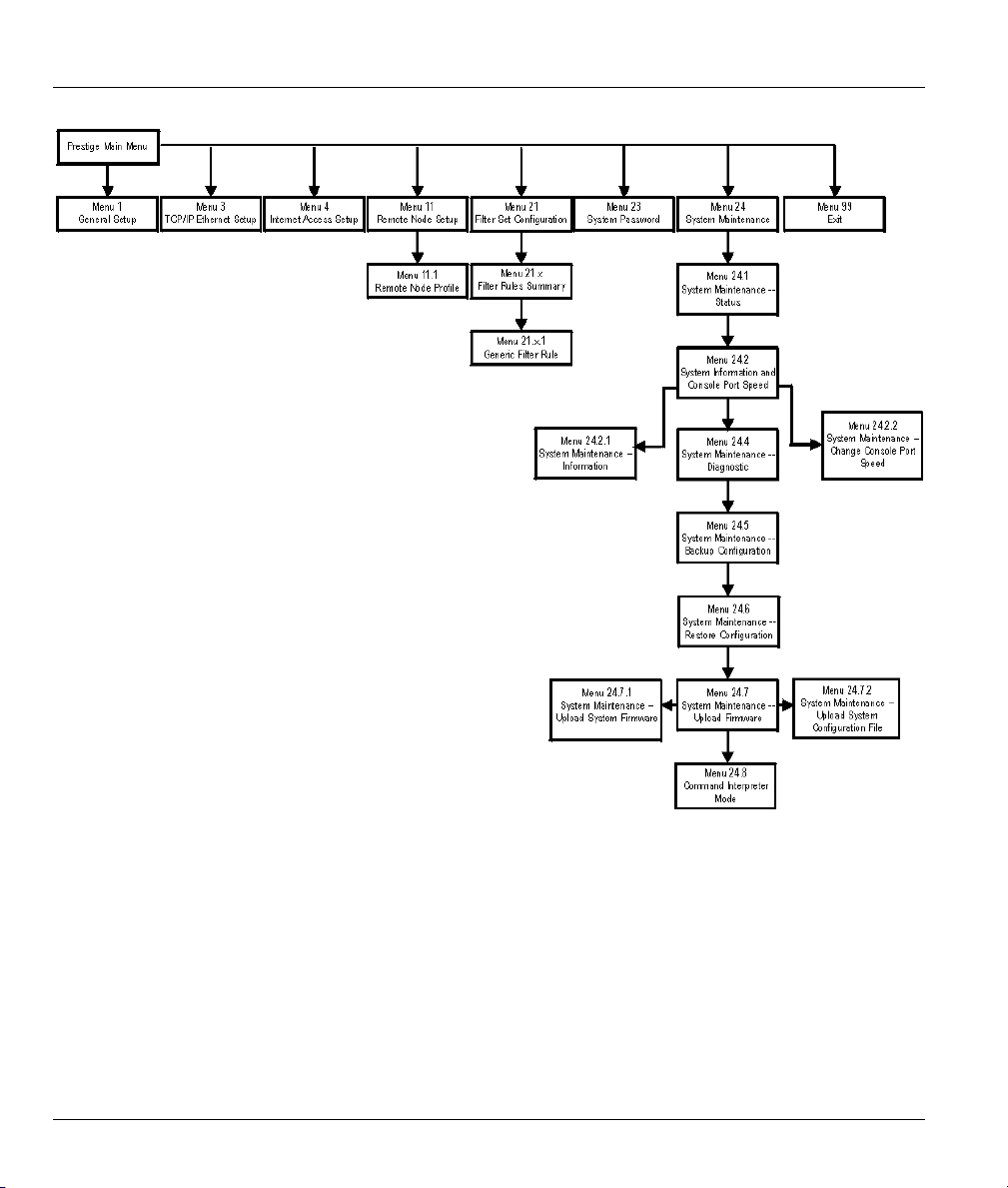
3.2 Prestige SMT Overview
The following figure gives you an overview of the various SMT menu screens of your Prestige.
Initial Setup 3-1
Prestige 650M ADSL Bridge
Figure 3-2 Prestige SMT Menu Overview
3.3 Navigating the SMT Interface
The SMT (System Management Terminal) is the interface that you use to configure your Prestige.
Several operations that you should be familiar with before you attempt to modify the configuration are
listed in the table below.
3-2 Initial Setup

Prestige 650M ADSL Bridge
Table 3-1 Main Menu Commands
OPERATION KEYSTROKE DESCRIPTION
Move down to
another menu
Move up to a
previous menu
Move to a “hidden”
menu
Move the cursor [ENTER] or
Entering
information
Required fields
N/A fields <N/A> Some of the fields in the SMT will show a <N/A>. This symbol
Save your
configuration
Exit the SMT Type 99, then press
[ENTER] To move forward to a submenu, type in the number of the desired
submenu and press [ENTER].
[ESC] Press [ESC] to move back to the previous menu.
Press [SPACE
BAR] to change No
to Yes then press
[ENTER].
[UP]/[DOWN] arrow
keys.
Type in or press
[SPACE BAR], then
press [ENTER].
<?> or ChangeMe
[ENTER] Save your configuration by pressing [ENTER] at the message
[ENTER].
Fields beginning with “Edit” lead to hidden menus and have a
default setting of No. Press [SPACE BAR] once to change No to
Yes, then press [ENTER] to go to the “hidden” menu.
Within a menu, press [ENTER] to move to the next field. You can
also use the [UP]/[DOWN] arrow keys to move to the previous
and the next field, respectively.
You need to fill in two types of fields. The first requires you to type
in the appropriate information. The second allows you to cycle
through the available choices by pressing [SPACE BAR].
All fields with the symbol <?> must be filled in order to be able to
save the new configuration.
All fields with ChangeMe must not be left blank in order to be
able to save the new configuration.
refers to an option that is Not Applicable.
“Press ENTER to confirm or ESC to cancel”. Saving the data on
the screen will take you, in most cases to the previous menu.
Type 99 at the main menu prompt and press [ENTER] to exit the
SMT interface.
After you enter the password, the SMT displays the main menu, as shown next.
Initial Setup 3-3

Prestige 650M ADSL Bridge
Copyright (c) 1994 - 2002 ZyXEL Communications Corp.
Prestige 650M-37 Main Menu
Getting Started
1. General Setup
3. TCP/IP Ethernet Setup
4. Internet Access Setup
Advanced Applications
11. Remote Node Setup
Enter Menu Selection Number:_
Advanced Management
21. Filter Set Configuration
23. System Password
24. System Maintenance
99. Exit
Figure 3-3 SMT Main Menu
3.3.1 System Management Terminal Interface Summary
Table 3-2 Main Menu Summary
# MENU TITLE DESCRIPTION
1 General Setup Use this menu to set up your general information.
3 TCP/IP Ethernet Setup Use this menu to set up your LAN connection.
4 Internet Access Setup A quick and easy way to set up an Internet connection.
11 Remote Node Setup Use this menu to set up the Remote Node for LAN-to-LAN connection,
including Internet connection.
21 Filter Set Configuration Use this menu to set up filters to provide security, etc.
23 System Password Use this menu to change your password.
24 System Maintenance This menu provides system status, diagnostics, software upload, etc.
99 Exit Use this to exit from SMT and return to a blank screen.
3.4 Changing the System Password
This is highly recommended!
Change the Prestige default password by following the steps shown next.
Step 1. Enter 23 in the main menu to display Menu 23 – System Password, as shown next.
3-4 Initial Setup

Prestige 650M ADSL Bridge
Step 2. Type your existing system password in the Old Password field, for example “1234”, and press
[ENTER].
Menu 23 – System Password
Old Password= ****
New Password= ?
Retype to confirm= ?
Enter here to CONFIRM or ESC to CANCEL:
Figure 3-4 Menu 23 – System Password
Step 3. Type your new system password in the New Password field (up to 30 characters), and press
[ENTER].
Step 4. Re-type your new system password in the Retype to confirm field for confirmation and press
[ENTER].
Note that as you type a password, the screen displays an asterisk “*” for each character you type.
3.4.1 Resetting the Prestige
If you forget your password or cannot access the Prestige, you will need to reload the factory-default
configuration file. Uploading this configuration file replaces the current configuration file with the factorydefault configuration file. This means that you will lose all previous configurations; the password will be
reset to “1234” and the LAN IP address to 192.168.1.1.
To obtain the default configuration file, download it from the ZyXEL FTP site, unzip it and save it in a
folder.
To upload the configuration file, follow the instructions in menu 24.6. For more information, refer to the
Firmware and Configuration File Maintenance chapter.
All custom settings will be lost once you reset to the default settings.
3.4.2 Methods of Restoring Prestige Factory–Defaults
You can erase the current configuration and restore factory defaults in two ways:
1. Upload the default configuration file via Telnet as described above. Refer to Chapter 8 in this
User’s Guide for more information on how to transfer a configuration file to your Prestige using
the SMT menus.
Initial Setup 3-5

Prestige 650M ADSL Bridge
2. Use the RESET button on the rear panel of the Prestige (see section 2.2.5).
3.5 SMT Menu 1: General Setup
Menu 1 – General Setup contains administrative and system-related information.
To enter menu 1 and fill in the required information, follow these steps:
Step 1. Enter 1 in main menu to display Menu 1 – General Setup.
Menu 1 - General Setup
System Name= P650M
Location=
Contact Person's Name=
Press ENTER to Confirm or ESC to Cancel:
Figure 3-5 Menu 1–General Setup
Step 2. The Menu 1 – General Setup screen appears, as shown next. Fill in the fields following the
explanation provided in the table shown next.
Table 3-3 General Setup Menu Fields
FIELD DESCRIPTION EXAMPLE
System Name Choose a descriptive name for identification purposes. This name can
be up to 30 alphanumeric characters long. Spaces are not allowed, but
dashes “-” and underscores "_" are accepted.
Location (optional) Enter the geographic location (up to 31 characters) of your Prestige. MyHouse
Contact Person's
Name (optional)
Enter the name (up to 30 characters) of the person in charge of this
Prestige.
Prestige
JohnDoe
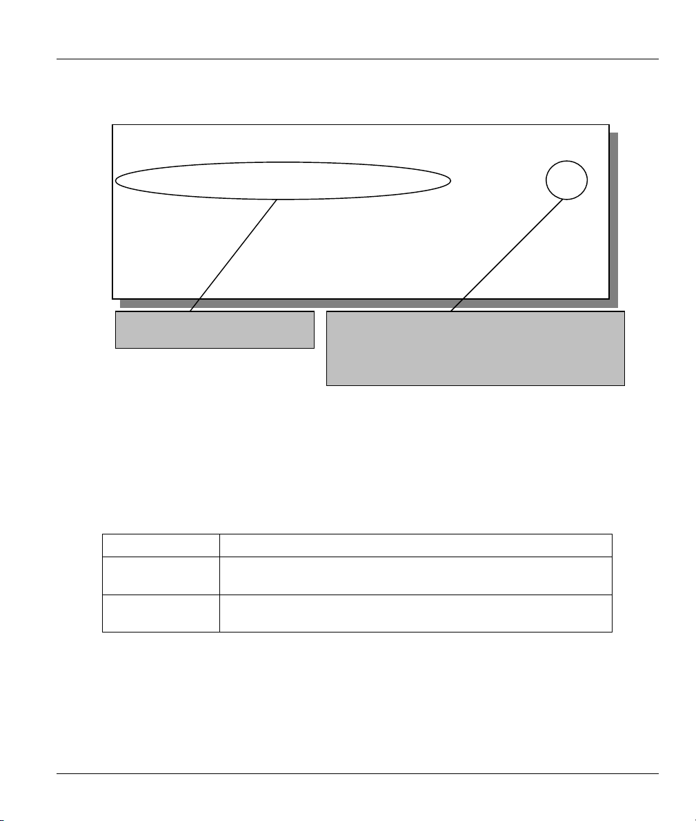
3.6 LANs and WANs
A LAN (Local Area Network) is a computer network limited to the immediate area, usually the same
building or floor of a building. A WAN (Wide Area Network), on the other hand, is an outside connection
to another network or the Internet.
3-6 Initial Setup
Prestige 650M ADSL Bridge
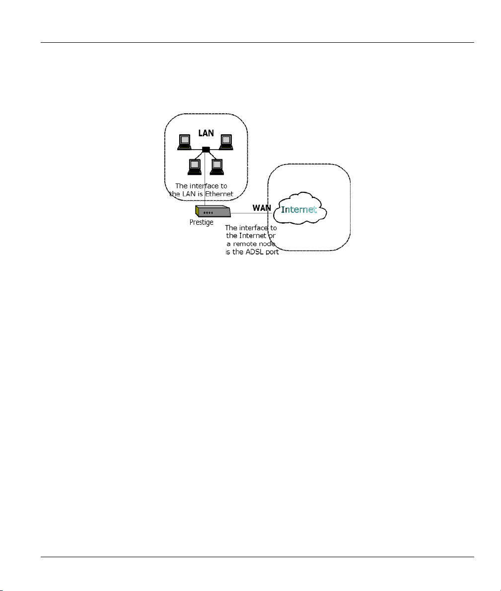
3.6.1 LANs, WANs and the Prestige
The actual physical connection determines whether the Prestige ports are LAN or WAN ports. There are
two separate IP networks, one inside, the LAN network; the other outside: the WAN network as shown
next:
Figure 3-6 LAN & WAN IPs
3.6.2 IP Address and Subnet Mask
Like houses on a street that share a common street name, the computers on a LAN share one common
network number.
Where you obtain your network number depends on your particular situation. If the ISP or your network
administrator assigns you a block of registered IP addresses, follow their instructions in selecting the IP
addresses and the subnet mask.
If the ISP did not explicitly give you an IP network number, then most likely you have a single user account
and the ISP will assign you a dynamic IP address when the connection is established. If this is the case, it is
recommended that you select a network number from 192.168.0.0 to 192.168.255.0 (ignoring the trailing
zero) and you must enable the Single User Account feature of the Prestige. The Internet Assigned Number
Authority (IANA) reserved this block of addresses specifically for private use; please do not use any other
number unless you are told otherwise. Let’s say you select 192.168.1.0 as the network number; which
covers 254 individual addresses, from 192.168.1.1 to 192.168.1.254 (zero and 255 are reserved). In other
words, the first three numbers specify the network number while the last number identifies an individual
computer on that network.
The subnet mask specifies the network number portion of an IP address. Your Prestige will compute the
subnet mask automatically based on the IP address that you entered. You don’t need to change the subnet
mask computed by the Prestige unless you are instructed to do otherwise.
Initial Setup 3-7
Prestige 650M ADSL Bridge
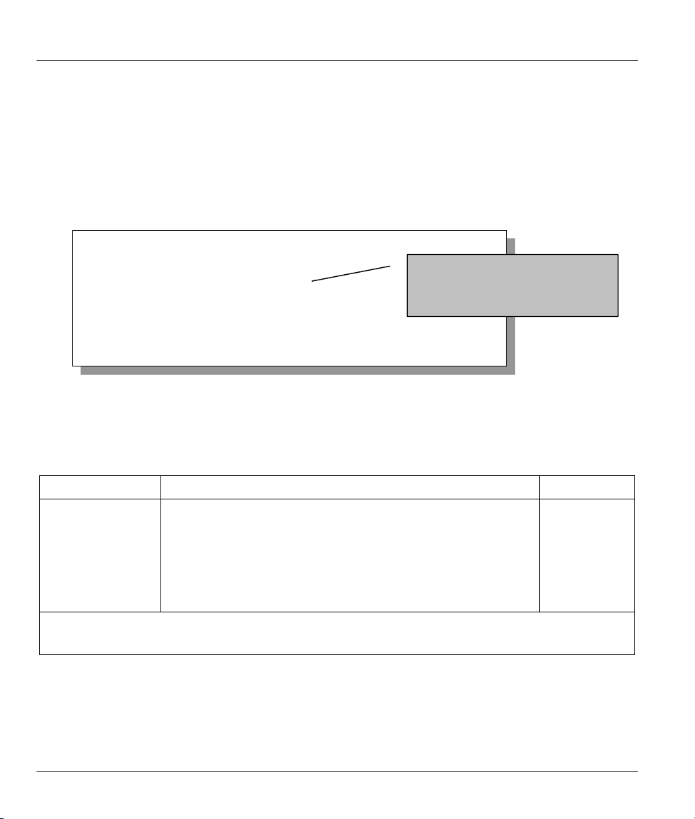
3.7 SMT Menu 3: TCP/IP LAN Setup
The Ethernet parameters of the Prestige are preset in the factory with the following values:
IP address of 192.168.1.1 with subnet mask of 255.255.255.0 (24 bits).
Use menu 3.2 to configure the IP address of your Prestige. You need to do this to be able to manage yopur
Prestige.
To edit menu 3.2, enter 3 from the main menu to display Menu 3 – Ethernet Setup. When menu 3 appears,
press 2 and press [ENTER] to display Menu 3.2 – TCP/IP and DHCP Ethernet Setup, as shown next
Menu 3.2 - TCP/IP Ethernet Setup
TCP/IP Setup:
IP Address= 192.68.1.1
IP Subnet Mask= 255.255.255.0
Press ENTER to Confirm or ESC to Cancel:
This is the IP address of the Prestige.
Your computer must be in the same
subnet as the Prestige in order to be
able to communicate with it.
Figure 3-7 Menu 3.2 – TCP/IP and DHCP Ethernet Setup
Follow the instructions in the following table to configure TCP/IP parameters for the Ethernet port.
:
Table 3-4 TCP/IP Ethernet Setup Menu Fields
FIELD DESCRIPTION EXAMPLE
TCP/IP Setup
IP Address Enter the (LAN) IP address of your Prestige in dotted decimal
notation
IP Subnet Mask Your Prestige will automatically calculate the subnet mask based on
the IP address that you assign. Unless you are implementing
subnetting, use the subnet mask computed by the Prestige.
When you have completed this menu, press [ENTER] at the prompt “Press ENTER to Confirm…” to save
your configuration, or press [ESC] at any time to cancel.
192.168.1.1
255.255.255.0
3-8 Initial Setup

Prestige 650M ADSL Bridge
Chapter 4
Internet Access
This chapter shows you how to configure your Prestige for Internet access.
4.1 Introduction
Menu 4 allows you to enter your Internet Access information in one screen. Menu 4 is actually a simplified
setup for one of the remote nodes that you can access in menu 11. Before you configure your Prestige for
Internet access, you need to collect your Internet account information from your ISP or telephone company.
Use the following table to record your Internet Account Information. Note that if you are using PPPoA
encapsulation the only ISP information you need is a login name and password. If you are using RFC 1483,
you do not need a login name or password.
Table 4-1 Internet Account Information
REQUIRED INFORMATION
Virtual Path Identifier (VPI): ____________
Virtual Channel Identifier (VCI): ____________
Multiplexing (VC-based or LLC-based):
Your device’s WAN IP Address (if given): __________________
Encapsulation:
RFC 1483
PPPoA
User Name: ____________ Password: ____________
VC LLC
4.2 VPI and VCI
Be sure to use the correct Virtual Path Identifier (VPI) and Virtual Channel Identifier (VCI) numbers
supplied by your ISP or telephone company. The valid range for the VPI is 0 to 255 and for the VCI is 32
to 65535 (0 to 31 is reserved for local management of ATM traffic). Please see the appendix on Virtual
Circuit Topology for more information.
Internet Access 4-1

Prestige 650M ADSL Bridge
4.3 Multiplexing
There are two conventions to identify what protocols the virtual circuit (VC) is carrying. Be sure to use the
multiplexing method required by your ISP.
4.3.1 VC–based Multiplexing
In this case, by prior mutual agreement, each protocol is assigned to a specific virtual circuit, for example,
VC1 carries IP, etc. VC-based multiplexing may be dominant in environments where dynamic creation of
large numbers of ATM VCs is fast and economical.
4.3.2 LLC–based Multiplexing
In this case one VC carries multiple protocols with protocol identifying information being contained in each
packet header. Despite the extra bandwidth and processing overhead, this method may be advantageous if it
is not practical to have a separate VC for each carried protocol, for example, if charging heavily depends on
the number of simultaneous VCs.
4.4 Encapsulation
Be sure to use the encapsulation method required by your ISP. The Prestige supports the following
methods.
4.4.1 PPPoA
Please refer to RFC 2364 for more information on PPP over ATM Adaptation Layer 5 (AAL5). Refer to
RFC 1661 for more information on PPP.
4.4.2 RFC 1483
RFC 1483 describes two methods for Multiprotocol Encapsulation over ATM Adaptation Layer 5 (AAL5).
The first method allows multiplexing of multiple protocols over a single ATM virtual circuit (LLC-based
multiplexing) and the second method assumes that each protocol is carried over a separate ATM virtual
circuit (VC-based multiplexing). Please refer to the RFC for more detailed information.
4.4.3 Encapsulation and Multiplexing Scenarios
For Internet access you should use the encapsulation and multiplexing methods used by your ISP. For
LAN-to-LAN applications, e.g., branch office and corporate headquarters, prior agreement on methods is
necessary because encapsulation and multiplexing cannot be automatically determined. Which methods to
use depends on how many VCs you have and how many different network protocols you need. Here are
some examples of more suitable combinations in such an application.
4-2 Internet Access

Prestige 650M ADSL Bridge
Scenario 1. One VC, Multiple Protocols
PPPoA (RFC-2364) encapsulation with VC-based multiplexing is the best combination because no extra
protocol identifying headers are needed. The PPPoA protocol already contains this information.
Scenario 2. One VC, One Protocol (IP)
Selecting RFC 1483 encapsulation with VC-based multiplexing requires the least amount of overhead (0
octets). However, if there is a potential need for multiple protocol support in the future, it may be safer to
select PPPoA encapsulation instead of RFC 1483, so you do not need to reconfigure either computer later.
Scenario 3. Multiple VCs
If you have an equal number (or more) of VCs than the number of protocols, then select RFC 1483
encapsulation and VC-based multiplexing.
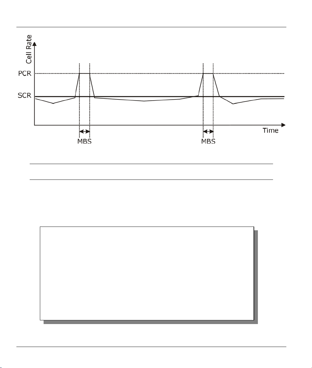
4.4.4 Traffic Shaping
Traffic Shaping is an agreement between the carrier and the subscriber to regulate the average rate and
“burstiness” or fluctuation of data transmission over an ATM network. This agreement helps eliminate
congestion, which is important for transmission of real time data such as audio and video connections.
Peak Cell Rate (PCR) is the maximum rate at which the sender can send cells. This parameter may be lower
(but not higher) than the maximum line speed. 1 ATM cell is 53 bytes (424 bits), so a maximum speed of
832 Kbps gives a maximum PCR of 1962 cells/sec. This rate is not guaranteed because it is dependent on
the line speed.
Sustained Cell Rate (SCR) is the mean cell rate of a bursty, on-off traffic source that can be sent at the peak
rate, and a parameter for burst-type traffic. SCR may not be greater than the PCR; the system default is 0
cells/sec.
Maximum Burst Size (MBS) is the maximum number of cells that can be sent at the PCR. After MBS is
reached, cell rates fall below SCR until cell rate averages to the SCR again. At this time, more cells (up to
the MBS) can be sent at the PCR again.
If the PCR, SCR or MBS is set to the default of “0”, the system will assign a
maximum value that correlates to your upstream line rate.
The following figure illustrates the relationship between PCR, SCR and MBS.
Internet Access 4-3
Prestige 650M ADSL Bridge
Figure 4-1 Example of Traffic Shaping
If the PCR is set to the default of “0”, the system will assign a maximum value
that correlates to your upstream line rate.
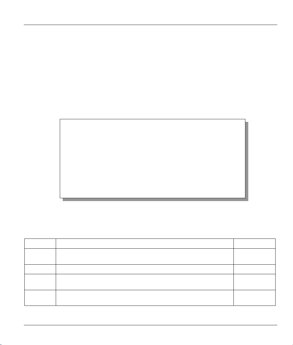
4.5 Internet Access Configuration
From the main menu, enter 4 to display Menu 4–Internet Access Setup, as shown next.
Menu 4 – Internet Access Setup
ISP's Name= Change Me
Encapsulation= RFC 1483
Multiplexing= LLC-based
VPI #= 0
VCI #= 35
ATM QoS Type= UBR
Peak Cell Rate (PCR)= 0
Sustain Cell Rate (SCR)= 0
Maximum Burst Size (MBS)= 0
My Login= N/A
My Password= N/A
Press ENTER to confirm or ESC to cancel:
Figure 4-2 Internet Access Setup
4-4 Internet Access

Prestige 650M ADSL Bridge
The following table contains instructions on how to configure your Prestige for Internet access.
Table 4-2 Internet Access Setup Menu Fields
FIELD DESCRIPTION EXAMPLE
ISP’s Name Enter the name of your Internet Service Provider. This
information is for identification purposes only.
Encapsulation Press [SPACE BAR] to select the method of encapsulation
used by your ISP. Choices are PPPoA or RFC 1483.
Multiplexing Press [SPACE BAR] to select the method of multiplexing used
by your ISP. Choices are VC-based or LLC-based.
VPI # Enter the Virtual Path Identifier (VPI) that the telephone
company gives you.
VCI # Enter the Virtual Channel Identifier (VCI) that the telephone
company gives you.
ATM QoS Type
Peak Cell Rate
(PCR)
Sustain Cell Rate
(SCR)= 0
Maximum Burst Size
(MBS)= 0
My Login Enter the login name that your ISP gives you. N/A
My Password Enter the password associated with the login name above. N/A
When you have completed this menu, press [ENTER] at the prompt “Press ENTER to Confirm…” to save
your configuration, or press [ESC] at any time to cancel.
Press [SPACE BAR] and select CBR (Continuous Bit Rate) to
specify fixed (always-on) bandwidth. Select UBR (Unspecified
Bit Rate) for applications that are non-time sensitive, such as
e-mail. Select VBR (Variable Bit Rate) for bursty traffic and
bandwidth sharing with other applications.
This is the maximum rate at which the sender can send cells.
Type the PCR.
Sustained Cell Rate is the mean cell rate of a bursty, on-off
traffic source that can be sent at the peak rate, and a
parameter for burst-type traffic. Type the SCR; it must be less
than the PCR.
Refers to the maximum number of cells that can be sent at the
peak rate. Type the MBS. The MBS must be less than 65535.
ChangeMe
RFC 1483
LLC-based
8
35
UBR
0
0
0
If all your settings are correct your Prestige should connect automatically to the Internet. If the connection
fails, note the error message that you receive on the screen and take the appropriate troubleshooting steps.
Internet Access 4-5


Prestige 650M ADSL Bridge
Chapter 5
Remote Node Configuration
This chapter shows you how to set up a remote node.
5.1 Remote Node Setup
A remote node is required for placing calls to a remote gateway. A remote node represents both the remote
gateway and the network behind it across a WAN connection. When you use menu 4 to set up Internet
access, you are configuring one of the remote nodes.
5.1.1 Remote Node Profile
To configure a remote node, follow these steps:
Step 1. From the main menu, enter 11 to display Menu 11-Remote Node Setup.
Step 2. When menu 11 appears, as shown in the following figure, type the number of the remote node that
you want to configure.
Menu 11 - Remote Node Setup
1. ChangeMe (ISP)
2. ________
3. ________
4. ________
5. ________
6. ________
7. ________
8. ________
Enter Node # to Edit:
Figure 5-1 Menu 11–Remote Node Setup
Step 3. Choose a remote node to configure by entering a number from 1 to 8.
Remote Node Configuration 5-1

Prestige 650M ADSL Bridge
Menu 11.1 - Remote Node Profile
Rem Node Name= ChangeMe Bridge:
Active= Yes Ethernet Addr Timeout(min)= 0
VPI #= 1
Encapsulation= RFC 1483 VCI #= 32
Multiplexing= LLC-based
ATM QoS Type= UBR
Incoming: Peak Cell Rate (PCR)= 0
Rem Login= N/A Sustain Cell Rate (SCR)= 0
Rem Password= N/A Maximum Burst Size (MBS)= 0
Outgoing:
My Login= N/A Filter Sets:
My Password= N/A Input Device Filters=
Authen= N/A Output Device Filters=
Press ENTER to Confirm or ESC to Cancel:
Figure 5-2 Menu 11.1-Remote Node Profile
Fill in the fields as described in the following table. Please see Chapter 4 for more background information.
Table 5-1 Remote Node Profile Menu Fields
FIELD DESCRIPTION EXAMPLE
Rem Node Name Type a unique, descriptive name of up to eight characters for this
node.
Active
Press [SPACE BAR] and then [ENTER] to select Yes to activate or
No to deactivate this node. Inactive nodes are displayed with a
minus sign “–“ in SMT menu 11.
Encapsulation
PPPoA refers to RFC-2364 (PPP Encapsulation over ATM
Adaptation Layer 5).
If you select RFC 1483 (Multiprotocol Encapsulation over ATM
Adaptation Layer 5) then Rem Login, Rem Password, My Login
and My Password fields are not applicable (N/A).
Multiplexing Press [SPACE BAR] and then [ENTER] to select the method of
multiplexing that your ISP uses, either VC-based or LLC-based.
Incoming:
Rem Login Type the login name that this remote node will use to call your
Prestige. The login name and the Rem Password will be used to
authenticate this node.
Rem Password Type the password used when this remote node calls your
Prestige.
Outgoing:
ChangeMe
Yes
RFC 1483
LLC-based
5-2 Remote Node Configuration

Prestige 650M ADSL Bridge
Table 5-1 Remote Node Profile Menu Fields
FIELD DESCRIPTION EXAMPLE
My Login Type the login name assigned by your ISP when the Prestige calls
this remote node.
My Password Type the password assigned by your ISP when the Prestige calls
this remote node.
Authen
Bridge:
Ethernet Addr
Timeout(min)
VPI # Enter the Virtual Path Identifier (VPI) that the ISP or telephone
VCI # Enter the Virtual Channel Identifier (VCI) that the ISP or telephone
ATM QoS Type
Peak Cell Rate
(PCR)
Sustain Cell Rate
We recommend you employ the strongest authentication protocol
possible. However, some vendors’ implementation includes a
specific authentication protocol in the user profile. It will disconnect
if the negotiated protocol is different from that in the user profile,
even when the negotiated protocol is stronger than specified. If the
peer disconnects right after a successful authentication, make sure
that you specify the correct authentication protocol when
connecting to such an implementation.
This field sets the authentication protocol used for outgoing calls.
Options for this field are:
CHAP/PAP – Your Prestige will accept either CHAP or PAP when
requested by this remote node.
CHAP – accept CHAP (Challenge Handshake Authentication
Protocol) only.
PAP – accept PAP (Password Authentication Protocol) only.
Type the time (in minutes) for the Prestige to retain the Ethernet
Address information in its internal tables while the line is down. If
this information is retained, your Prestige will not have to recompile
the tables when the line comes back up.
company gives you.
company gives you.
Press [SPACE BAR] and select CBR (Continuous Bit Rate) to
specify fixed (always-on) bandwidth. Select UBR (Unspecified Bit
Rate) for applications that are non-time sensitive, such as e-mail.
This is the maximum rate at which the sender can send cells. Type
the PCR.
Sustained Cell Rate is the mean cell rate of a bursty, on-off traffic
CHAP/PAP
0
8
35
UBR
0
0
Remote Node Configuration 5-3

Prestige 650M ADSL Bridge
Table 5-1 Remote Node Profile Menu Fields
FIELD DESCRIPTION EXAMPLE
(SCR)= 0 source that can be sent at the peak rate, and a parameter for burst-
type traffic. Type the SCR; it must be less than the PCR.
Maximum Burst
Size (MBS)= 0
Filter Sets:
Input Device Filters Apply filters for incoming traffic. See Chapter 6 for information on
Output Device
Filters
When you have completed this menu, press [ENTER] at the prompt “Press ENTER to confirm or ESC to
cancel” to save your configuration or press [ESC] to cancel and go back to the previous screen.
Refers to the maximum number of cells that can be sent at the
peak rate. Type the MBS. The MBS must be less than 65535.
filters.
Apply filters for traffic leaving the Prestige. See Chapter 6 for
information on filters.
0
5-4 Remote Node Configuration

Prestige 650M ADSL Bridge
Chapter 6
Filter Set Configuration
This chapter shows you how to create and apply filters.
6.1 About Filtering
Your Prestige uses filters to decide whether or not to allow passage of data packets. Data filtering examines
the data to determine if the packet should be allowed to pass. Data filters are divided into incoming and
outgoing filters, depending on the direction of the packet relative to a port.
Filter Set Configuration 6-1

Prestige 650M ADSL Bridge
Filter Set
Start
Packet
intoFilter
Fetch First
Filter Set
Fetch Next
Filter Set
Yes
Next Filter Set
Available?
No
No
Fetch Next
Filter Rule
Yes
Next filter
Rule
Available?
Check
Next
Rule
Fetch First
Filter Rule
No
Active?
Execute
Filter Rule
Drop
Yes
Forward
Accept PacketDrop Packet
Figure 6-1 Filter Rule Process
You can apply up to four filter sets to a particular port to block various types of packets. Because each filter
set can have up to six rules, you can have a maximum of 24 rules active for a single port.
6-2 Filter Set Configuration

Prestige 650M ADSL Bridge
6.2 Configuring a Filter Set
To configure a filter set, follow the steps shown next.
Step 1. Enter 21 in the main menu to display Menu 21-Filter Set Configuration
Filter
Set #
-----1
2
3
4
5
6
Menu 21 - Filter Set Configuration
Comments
-----------------______________
______________
______________
______________
______________
______________
Enter Filter Set Number to Configure= 0
Press ENTER to Confirm or ESC to Cancel:
Edit Comments= N/A
Filter
Set #
----- 7
8
9
10
11
12
Comments
-----------------______________
______________
______________
______________
______________
______________
Figure 6-2 Menu 21–Filter Set Configuration
Step 2. Type the filter set to configure (no. 1 to 12) and press [ENTER]
.
Step 3. Type a descriptive name or comment in the Edit Comments field and press [ENTER].
Step 4. Press [ENTER] at the message
Summary (that is, if you selected filter set 1 in menu 21).
Menu 21.1 - Filter Rules Summary
# A Type Filter Rules M m n
- - ---- --------------------------------------------------------------- - - 1 N
2 N
3 N
4 N
5 N
6 N
Enter Filter Rule Number (1-6) to Configure:
“Press ENTER to confirm…” to display Menu 21.1–Filter Rules
Figure 6-3 Menu 21.1–Filter Rules Summary
Filter Set Configuration 6-3

Prestige 650M ADSL Bridge
6.2.1 Filter Rules Summary Menus
The following tables briefly describe the abbreviations used in menus 21.1 and 21.2.
Table 6-1 Abbreviations Used in the Filter Rules Summary Menu
FIELD DESCRIPTION
# The filter rule number: 1 to 6.
A Active: “Y” means the rule is active. “N” means the rule is inactive.
Type The type of filter rule: “GEN” for Generic
Filter Rules These parameters are displayed here.
M More.
“Y” means there are more rules to check which form a rule chain with the present rule.
An action cannot be taken until the rule chain is complete.
“N” means there are no more rules to check. You can specify an action to be taken for
instance, forward the packet, drop the packet or check the next rule. For the latter, the
next rule is independent of the rule just checked.
m Action Matched.
“F” means to forward the packet immediately and skip checking the remaining rules.
“D” means to drop the packet.
“N“ means to check the next rule.
n Action Not Matched.
“F” means to forward the packet immediately and skip checking the remaining rules.
“D” means to drop the packet.
“N” means to check the next rule.
Table 6-2 Rule Abbreviations Used
FILTER TYPE DESCRIPTION
GEN
Off Offset
Len Length
6.3 Generic Filter Rule
The purpose of generic rules is to allow you to filter non-IP packets. For generic rules, the Prestige treats a
packet as a byte stream as opposed to an IP packet. You specify the portion of the packet to check with the
Offset (from 0) and the Length fields, both in bytes. The Prestige applies the Mask (bit-wise ANDing) to
6-4 Filter Set Configuration
Prestige 650M ADSL Bridge
the data portion before comparing the result against the Value to determine a match. The Mask and Value
are specified in hexadecimal numbers.
Two hexadecimal digits represent a byte, so if the length is 4, the value in either field will take 8 digits, e.g.,
FFFFFFFF.
6.3.1 Example Generic Filter Rule Configuration
Step 1. Type a filter set number in Menu 21–Filter Set Configuration, (“5” in this example), and press
[ENTER] to display menu 21.5.
Step 2. Type a filter rule number in Menu 21.5–Filter Rules Summary, (“1” in this example), and press
[ENTER] to display Menu 21.5.1–Generic Filter Rule (shown next).
Menu 21.5.1 - Generic Filter Rule
Press ENTER to Confirm or ESC to Cancel:
Filter #: 5,1
Active= No
Offset= 0
Length= 0
Mask= N/A
Value= N/A
More= No Log= None
Action Matched= Check Next Rule
Action Not Matched= Check Next Rule
Press Space Bar to Toggle.
Figure 6-4 Menu 21.5.1
The table, shown next, describes the fields in Menu 21.5.1
Table 6-3 Menu 21.5.1
–Generic Filter Rule
–Generic Filter Rule.
– Generic Filter Rule Fields
FIELD DESCRIPTION EXAMPLE
Filter # This is the filter set, filter rule coordinates, for instance, 2, 3 refers to the
5,1
second filter set and the third rule of that set.
Active
Offset Type the starting byte of the data portion in the packet that you want to
Length Type the byte count of the data portion in the packet that you want to
Select Yes to turn on or No to turn off the filter rule. No
0
compare. The range for this field is from 0 to 255.
0
compare. The range for this field is 0 to 8.
Filter Set Configuration 6-5

Prestige 650M ADSL Bridge
Table 6-3 Menu 21.5.1 – Generic Filter Rule Fields
FIELD DESCRIPTION EXAMPLE
Mask Type the mask (in Hexadecimal) to apply to the data portion before
comparison.
Value Type the value (in Hexadecimal) to compare with the data portion.
More
Log Select the logging option from the following:
Action
Matched
Action Not
Matched
When you have completed this menu, press [ENTER] at the prompt “Press ENTER to confirm or ESC to
cancel” to save your configuration or press [ESC] to cancel and go back to the previous screen.
If Yes, a matching packet is passed to the next filter rule before an action
is taken or else the packet is disposed of according to the action fields.
If More is Yes, then Action Matched and Action Not Matched will be
N/A.
None – No packets will be logged.
Action Matched – Only matching packets and rules will be logged.
Action Not Matched – Only packets that do not match the rule
parameters will be logged.
Both – All packets will be logged.
Select the action for a matching packet. Choices are Check Next Rule,
Forward or Drop.
Select the action for a packet not matching the rule. Choices are Check
Next Rule, Forward or Drop.
No
None
Check Next
Rule
Check Next
Rule
6.4 Filter Configuration Example
Let us look at a sample filter.
Step 1. Enter 21 from the main menu to open Menu 21-Filter Set Configuration.
Step 2. Enter the index of the filter set you want to configure (in this case 3)
Step 3. Enter a descriptive name or comment in the Edit Comments field (in this case, test).
Step 4. Press [ENTER] at the message
“Press ENTER to confirm or ESC to cancel” to open Menu 21.3-
Filter Rules Summary.
Step 5. Enter 1 to configure the first filter rule. When you press [ENTER] to confirm, the following screen
appears. Note that there is only one filter rule in this set. Make the entries in this menu as shown
next.
6-6 Filter Set Configuration
.
Prestige 650M ADSL Bridge
f
(
Step 6. When you press [ENTER] to confirm, you will see the next screen. Note that there is only one
filter rule in this set.
Menu 21.3 - Filter Rules Summary
# A Type Filter Rules M m n
- - ---- --------------------------------------------------------------- - - 1 Y Gen Off=9, Len=4, Mask=789abcde, Value=789abcde N F D
2 N
3 N
4 N
5 N
6 N
Enter Filter Rule Number (1-6) to Configure: 1
This shows what you configured in
the previous menu.
M = N means an action can be taken immediately. The
action is to drop the packet (m = D) if the action is
matched and to forward the packet immediately (n = F) i
the action is not matched no matter whether there are
more rules to be checked
there are not in this example).
Figure 6-5 Sample Filter Rules Summary – Menu 21.3
6.5 Applying Filters
This section shows you where to apply the filters after you design them. Filter rules may be configured in
menu 21.
Table 6-4 Filter Set Types
FILTER SETS DESCRIPTION
Input Filter Sets: Apply filters for incoming traffic. You may apply device filter rules.
See earlier in this chapter for information on filters.
Output Filter Sets: Apply filters for traffic leaving the Prestige. You may apply device
filters. See earlier in this section for information on filters.
6.5.1 Remote Node Filters
Go to menu 11.1 (shown next) and type the number(s) of the filter set(s) as appropriate. You can cascade up
to four filter sets by typing their numbers separated by commas.
Filter Set Configuration 6-7
Prestige 650M ADSL Bridge
Menu 11.1 - Remote Node Profile
Rem Node Name= Change Me
Active= Yes
Encapsulation= RFC 1483
Multiplexing= LLC-based
Incoming:
Rem Login= N/A
Rem Password= N/A
Outgoing:
My Login= N/A
My Password= N/A
Authen= N/A
Press ENTER to Confirm or ESC to Cancel:
Bridge:
Ethernet Addr Timeout(min)= 0
VPI #= 0
VCI #= 33
ATM QoS Type= CBR
Peak Cell Rate (PCR)= 0
Sustain Cell Rate (SCR)= 0
Maximum Burst Size (MBS)= 0
Filter Sets:
Input Device Filters=
Output Device Filters=
Figure 6-6 Filtering Remote Node Traffic
6-8 Filter Set Configuration

Prestige 650M ADSL Bridge
Chapter 7
System Information and Diagnosis
This chapter covers the information and diagnostic tools in SMT menus 24.1 to 24.4 and 24.8.
7.1 Introduction
These menus display system status, port status and use of diagnostic tools when problems occur and an
introduction to the command interface.
Enter 24 in the main menu to display Menu 24
Menu 24 - System Maintenance
Enter Menu Selection Number:
1. System Status
2. System Information and Console Port Speed
4. Diagnostic
5. Backup Configuration
6. Restore Configuration
7. Upload Firmware
8. Command Interpreter Mode
– System Maintenance, shown next.
Figure 7-1 Menu 24 – System Maintenance
7.2 System Status
System Status displays status and statistics of the Prestige. Menu 24.1 – System Maintenance – Status is
meant for diagnostic purposes.
From the main menu, enter 24 to display Menu 24 – System Maintenance. Enter 1 to display Menu 24.1 –
System Maintenance – Status, shown next.
System Information and Diagnosis 7-1

Prestige 650M ADSL Bridge
Menu 24.1 - System Maintenance - Status 01:30:36
Thu. Oct. 30, 2002
Node-Lnk Status TxPkts RxPkts Errors Tx B/s Rx B/s Up Time
1-1483 N/A 0 0 0 0 0 0:00:00
2 N/A 0 0 0 0 0 0:00:00
3 N/A 0 0 0 0 0 0:00:00
4 N/A 0 0 0 0 0 0:00:00
5 N/A 0 0 0 0 0 0:00:00
6 N/A 0 0 0 0 0 0:00:00
7 N/A 0 0 0 0 0 0:00:00
8 N/A 0 0 0 0 0 0:00:00
My WAN IP (from ISP): 0.0.0.0
Ethernet: WAN:
Status: 100M/Full Duplex Tx Pkts: 483 Line Status: Wait for Init
Collisions: 0 Rx Pkts: 581 Upstream Speed: 0 kbps
CPU Load = 2.76% Downstream Speed: 0 kbps
Press Command:
COMMANDS: 1-Reset Counters ESC-Exit
Figure 7-2 Menu 24.1
– System Maintenance – Status
The following table describes the fields present in Menu 24.1 – System Maintenance – Status.
Table 7-1 System Maintenance – Status Menu Fields
FIELD DESCRIPTION
Node-Lnk
Status This is the status of the remote node.
TxPkts This is the number of transmitted packets to this remote node.
RxPkts This is the number of received packets from this remote node.
Errors This is the number of error packets on this connection.
Tx B/s This is the transmission rate in bytes per second.
Rx B/s This is the receiving rate in bytes per second.
Up Time This is the time this channel has been connected to the current remote node.
My WAN IP
(from ISP)
Ethernet This is the statistics for the LAN.
Status This is the current status of the LAN.
Collisions This is the number of collisions.
This is the node index number and link type. Link types are: PPPoA and 1483.
This is the WAN IP address you entered from your ISP.
7-2 System Information and Diagnosis

Prestige 650M ADSL Bridge
Table 7-1 System Maintenance – Status Menu Fields
FIELD DESCRIPTION
Tx Pkts This is the number of transmitted packets to the LAN.
Rx Pkts This is the number of received packets from the LAN.
CPU Load This specifies the percentage of CPU utilization.
WAN This is the statistics for the WAN.
Line Status
Upstream
Speed
Downstream
Speed
Commands
This is the current status of the xDSL line which can be Up or Down.
This is the current upstream rate.
Shows the current downstream rate.
1 Enter 1 to reset the counters
ESC Press [ESC] to display the previous screen.
7.3 System Information and Console Port Speed
This section describes your system and allows you to choose different console port speeds. To display the
System Information and Console Port Speed menu, follow the steps shown next.
Step 1. Enter 24 to display Menu 24 – System Maintenance.
Step 2. Enter 2 to display Menu 24.2 –System Information and Console Port Speed.
Step 3. From this menu you have two choices as shown in the next figure:
Menu 24.2 - System Information and Console Port Speed
1. System Information
Please enter selection:
2. Console Port Speed
Figure 7-3 Menu 24.2 – System Information and Console Port Speed
System Information and Diagnosis 7-3

Prestige 650M ADSL Bridge
7.3.1 System Information
Enter 1 in menu 24.2 to display the screen shown next.
Menu 24.2.1 - System Maintenance - Information
Name: P650M
Routing: BRIDGE
ZyNOS F/W Version: V3.40(kk.o)b1 | 1/17/2003
ADSL Chipset Vendor: Alcatel, Version 4.9.10
Standard: Multi-Mode
LAN
Ethernet Address: 00:a0:c5:01:23:45
IP Address: 192.168.1.1
IP Mask: 255.255.255.0
DHCP: None
Press ESC or RETURN to Exit:
Figure 7-4 Menu 24.2.1 – System Maintenance – Information
Table 7-2 Fields in System Maintenance
FIELD DESCRIPTION
Name This field displays the system name of your Prestige. This information can be
changed in Menu 1 – General Setup.
Routing This field shows the kind of routing used by the Prestige.
ZyNOS F/W Version This field displays the ZyNOS (ZyXEL Network Operating System) system
firmware version. ZyNOS is a registered trademark of ZyXEL Communications
Corporation.
ADSL Chipset Vendor This is the chipset used in the Prestige.
Version This field displays the ADSL Chipset version.
Standard This refers to the operational protocol the Prestige and the DSLAM (Digital
Subscriber Line Access Multiplexer) are using.
LAN
Ethernet Address This field displays to the Ethernet MAC (Media Access Control) of your
Prestige.
IP Address This is the IP address of the Prestige in dotted decimal notation.
IP Mask This shows the subnet mask of the Prestige.
DHCP This field shows the DHCP setting of the Prestige.
7-4 System Information and Diagnosis
Prestige 650M ADSL Bridge
7.3.2 Console Port1 Speed
You can set up different port speeds for the console port through Menu 24.2.2 – System Maintenance –
Console Port Speed. Your Prestige supports 9600 (default), 19200, 38400 and 57600bps console port
speeds.
Enter 2 in menu 24.2 to display the screen shown next. Press [SPACE BAR] and then [ENTER] to select
the desired speed in menu 24.2.2, as shown in the following figure.
Menu 24.2.2 – System Maintenance – Change Console Port Speed
Console Port Speed: 9600
Press ENTER to Confirm or ESC to Cancel:
Figure 7-5 Menu 24.2.2 – System Maintenance – Change Console Port Speed
After you changed the console port speed on your Prestige, you must also make the same change to the
console port speed parameter of your communication software.
7.4 Diagnostic
The diagnostic facility allows you to test the different aspects of your Prestige to determine if it is working
properly. Menu 24.4 allows you to choose among various types of diagnostic tests to evaluate your system.
Follow the procedure next display menu 24.4.
Step 1. From the main menu, enter 24 to display Menu 24 – System Maintenance.
Step 2. Enter 4 to display Menu 24.4 – System Maintenance – Diagnostic, shown next.
1
The console port is inside this product and is for advanced troubleshooting purposes only. Do not open the
device to access the console port as this will void your warranty.
System Information and Diagnosis 7-5

Prestige 650M ADSL Bridge
xDSL
1. Reset xDSL
TCP/IP
12. Ping Host
Menu 24.4 - System Maintenance – Diagnostic
Enter Menu Selection Number:
Host IP Address= N/A
System
21. Reboot System
22. Command Mode
Figure 7-6 Menu 24.4 – System Maintenance – Diagnostic
The following table describes the diagnostic tests available in menu 24.4 for and the connections.
Table 7-3 System Maintenance Menu – Diagnostic
FIELD DESCRIPTION
Reset xDSL Type 1 to re-initialize the xDSL link to the telephone company.
Reboot System Type 21 to reboot the Prestige.
Ping Host
Host IP Address Enter the host IP address that you want to ping.
Command Mode Type 22 to test and diagnose your Prestige in command interpreter mode.
Enter 12, enter the IP address of the host in the Host IP Address field and then
press [ENTER] to ping a host IP address.
7.5 Command Interpreter Mode
The Command Interpreter (CI) is primarily for advanced users only, featuring some low-level setup and
diagnostic functions.
See the included disk or the zyxel.com web site for more detailed information on CI commands.
Enter 8 from Menu 24 – System Maintenance or 22 from menu 22.4. A list of valid commands can be
found by typing help or ? at the command prompt. Type “exit” to return to the SMT main menu when
finished.
7-6 System Information and Diagnosis

Prestige 650M ADSL Bridge
1. System Status
2. System Information and Console Port Speed
4. Diagnostic
5. Backup Configuration
6. Restore Configuration
7. Firmware Update
8. Command Interpreter Mode
Enter Menu Selection Number:
Menu 24 - System Maintenance
Figure 7-7 Command Mode in Menu 24
Copyright (c) 1994 - 2003 ZyXEL Communications Corp.
P650M> ?
Valid commands are:
sys exit ether wan
ip bridge
P650M>
Figure 7-8 Valid Commands
System Information and Diagnosis 7-7


Prestige 650M ADSL Bridge
Chapter 8
Firmware and Configuration File
Maintenance
This chapter shows you how to back up and restore your configuration file as well as upload new
firmware and a new configuration file.
8.1 Identifying Your Product
Look at the bottom of your product for a label that contains the product name. If you’re looking for new
firmware, you should first look for firmware of this exact name, including the suffix, for example P650M-
31.
If you’re unsure of the name or can’t find the exact firmware name, please contact customer support or your
vendor.
8.2 Filename Conventions
The configuration file (often called the romfile or rom-0) contains the factory default settings in the menus
such as password, DHCP Setup, TCP/IP Setup, etc. It arrives from ZyXEL with a “rom” filename
extension. Once you have customized the Prestige's settings, they can be saved back to your computer under
a filename of your choosing.
ZyNOS (ZyXEL Network Operating System sometimes referred to as the “ras” file) is the system firmware
and has a “bin” filename extension. With many FTP and TFTP clients, the filenames are similar to those
seen next.
ftp> put firmware.bin ras
This is a sample FTP session showing the transfer of the computer file " firmware.bin" to the Prestige.
ftp> get rom-0 config.cfg
This is a sample FTP session saving the current configuration to the computer file “config.cfg”.
If your (T)FTP client does not allow you to have a destination filename different than the source, you will
need to rename them as the Prestige only recognizes “rom-0” and “ras”. Be sure you keep unaltered copies
of both files for later use.
The following table is a summary. Please note that the internal filename refers to the filename on the
Prestige and the external filename refers to the filename not
Firmware and Configuration File Maintenance 8-1
on the Prestige, that is, on your computer, local

Prestige 650M ADSL Bridge
network or FTP site and so the name (but not the extension) may vary. After uploading new firmware, see
the ZyNOS F/W Version field in Menu 24.2.1 – System Maintenance – Information to confirm that you
have uploaded the correct firmware version.
Table 8-1 Filename Conventions
FILE TYPE INTERNAL NAME EXTERNAL NAME DESCRIPTION
Configuration
File
Firmware Ras This is the generic name for the
Rom-0 This is the configuration filename on
the Prestige. Uploading the rom-0 file
replaces the entire ROM file system,
including your Prestige configurations,
system-related data (including the
default password), the error log and
the trace log.
ZyNOS firmware on the Prestige.
*.rom
*.bin
8.3 Backup Configuration
The Prestige displays messages explaining how to backup, restore and upload
files via Telnet in menus 24.5, 24.6, 24.7.1 and 24.7.2.
Enter 5 from Menu 24 - System Maintenance to backup the current Prestige configuration on your
computer. Backup is highly recommended once your Prestige is functioning properly. FTP is the preferred
methods for backing up your current configuration to your computer since it is fastest. Any serial
communications program should work fine; however, you must use Xmodem protocol to perform the
download/upload and you don’t have to rename the files.
Please note that terms “download” and “upload” are relative to the computer. Download means to transfer
from the Prestige to the computer, while upload means from your computer to the Prestige.
8.3.1 Backup Configuration
Follow the instructions as shown in the next screen.
8-2 Firmware and Configuration File Maintenance

Prestige 650M ADSL Bridge
Menu 24.5 - Backup Configuration
To transfer the configuration file to your computer, follow the procedure
below:
1. Launch the FTP client on your computer.
2. Type "open" and the IP address of your system. Then type "root" and
SMT password as requested.
3. Locate the 'rom-0' file.
4. Type 'get rom-0' to back up the current system configuration to your
computer.
For details on FTP commands, please consult the documentation of your FTP
client program. For details on backup using TFTP (note that you must remain
in this menu to back up using TFTP), please see your user manual.
Figure 8-1 Telnet in Menu 24.5
8.3.2 Using the FTP Command from the Command Line
Step 1. Launch the FTP client on your computer.
Step 2. Enter “open”, followed by a space and the IP address of your Prestige.
Step 3. Press [ENTER] when prompted for a username.
Step 4. Enter your password as requested (the default is “1234”).
Step 5. Enter “bin” to set transfer mode to binary.
Step 6. Use “get” to transfer files from the Prestige to the computer, for example, “get rom-0 config.rom”
transfers the configuration file on the Prestige to your computer and renames it “config.rom”. See
earlier in this chapter for more information on filename conventions.
Step 7. Enter “quit” to exit the ftp prompt.
8.3.3 Example FTP Commands
Firmware and Configuration File Maintenance 8-3

Prestige 650M ADSL Bridge
331 Enter PASS command
Password:
230 Logged in
ftp> bin
200 Type I OK
ftp> get rom-0 zyxel.rom
200 Port command okay
150 Opening data connection for STOR ras
226 File received OK
ftp: 16384 bytes sent in 1.10Seconds 297.89Kbytes/sec.
ftp> quit
Figure 8-2 FTP Session Example
8.3.4 GUI-based FTP Clients
The following table describes some of the commands that you may see in GUI-based FTP clients.
Table 8-2 General Commands for GUI-based FTP Clients
COMMAND DESCRIPTION
Host Address Enter the address of the host server.
Login Type Anonymous.
This is when a user I.D. and password is automatically supplied to the
server for anonymous access. Anonymous logins will work only if your
ISP or service administrator has enabled this option.
Normal.
The server requires a unique User ID and Password to login.
Transfer Type Transfer files in either ASCII (plain text format) or in binary mode.
Initial Remote Directory Specify the default remote directory (path).
Initial Local Directory Specify the default local directory (path).
8.3.5 Backup Configuration Using TFTP
The Prestige supports the up/downloading of the firmware and the configuration file using TFTP (Trivial
File Transfer Protocol) over LAN. Although TFTP should work over WAN as well, it is not recommended.
To use TFTP, your computer must have both telnet and TFTP clients. To backup the configuration file,
follow the procedure shown next.
8-4 Firmware and Configuration File Maintenance

Prestige 650M ADSL Bridge
Step 1. Use Telnet from your computer to connect to the Prestige and log in. Because TFTP does not have
any security checks, the Prestige records the IP address of the telnet client and accepts TFTP
requests only from this address.
Step 2. Put the SMT in command interpreter (CI) mode by entering 8 in Menu 24 - System Maintenance.
Step 3. Enter command “sys stdio 0” to disable the SMT timeout, so the TFTP transfer will not be
interrupted. Enter command “sys stdio 5” to restore the five-minute SMT timeout (default) when
the file transfer is complete.
Step 4. Launch the TFTP client on your computer and connect to the Prestige. Set the transfer mode to
binary before starting data transfer.
Step 5. Use the TFTP client (see the example below) to transfer files between the Prestige and the
computer. The file name for the configuration file is “rom-0” (rom-zero, not capital o).
Note that the telnet connection must be active and the SMT in CI mode before and during the TFTP
transfer. For details on TFTP commands (see following example), please consult the documentation of your
TFTP client program. For UNIX, use “get” to transfer from the Prestige to the computer and “binary” to set
binary transfer mode.
8.3.6 TFTP Command Example
The following is an example TFTP command:
tftp [-i] host get rom-0 config.rom
where “i” specifies binary image transfer mode (use this mode when transferring binary files), “host” is the
Prestige IP address, “get” transfers the file source on the Prestige (rom-0, name of the configuration file on
the Prestige) to the file destination on the computer and renames it config.rom.
8.3.7 GUI-based TFTP Clients
The following table describes some of the fields that you may see in GUI-based TFTP clients.
Table 8-3 General Commands for GUI-based TFTP Clients
COMMAND DESCRIPTION
Host Enter the IP address of the Prestige. 192.168.1.1 is the Prestige’s default IP address
when shipped.
Send/Fetch Use “Send” to upload the file to the Prestige and “Fetch” to back up the file on your
computer.
Local File Enter the path and name of the firmware file (*.bin extension) or configuration file (*.rom
extension) on your computer.
Firmware and Configuration File Maintenance 8-5

Prestige 650M ADSL Bridge
Table 8-3 General Commands for GUI-based TFTP Clients
COMMAND DESCRIPTION
Remote File This is the filename on the Prestige. The filename for the firmware is “ras” and for the
configuration file, is “rom-0”.
Binary Transfer the file in binary mode.
Abort Stop transfer of the file.
8.4 Restore Configuration
This section shows you how to restore a previously saved configuration. Note that this function erases the
current configuration before restoring a previous back up configuration; please do not attempt to restore
unless you have a backup configuration file stored on disk.
FTP is the preferred method for restoring your current computer configuration to your Prestige since FTP is
faster. Please note that you must wait for the system to automatically restart after the file transfer is
complete.
WARNING!
DO NOT INTERUPT THE FILE TRANSFER PROCESS AS THIS MAY
PERMANENTLY DAMAGE YOUR PRESTIGE.
8.4.1 Restore Using FTP
For details about backup using (T)FTP please refer to earlier sections on FTP and TFTP file upload in this
chapter.
8-6 Firmware and Configuration File Maintenance

Prestige 650M ADSL Bridge
Menu 24.6 - System Maintenance - Restore Configuration
To transfer the firmware and configuration file to your workstation, follow the procedure
below:
1. Launch the FTP client on your computer.
2. Type "open" and the IP address of your system. Then type "root" and
SMT password as requested.
3. Type "put backupfilename rom-0" where backupfilename is the name of
your backup configuration file on your workstation and rom-0 is the
remote file name on the system. This restores the configuration to
your system.
4. The system reboots automatically after a successful file transfer
For details on FTP commands, please consult the documentation of your FTP
client program. For details on backup using TFTP (note that you must remain
in this menu to back up using TFTP), please see your user manual.
Figure 8-3 Telnet into Menu 24.6
Step 1. Launch the FTP client on your computer.
Step 2. Enter “open”, followed by a space and the IP address of your Prestige.
Step 3. Press [ENTER] when prompted for a username.
Step 4. Enter your password as requested (the default is “1234”).
Step 5. Enter “bin” to set transfer mode to binary.
Step 6. Find the “rom” file (on your computer) that you want to restore to your Prestige.
Step 7. Use “put” to transfer files from the Prestige to the computer, for example, “put config.rom rom-0”
transfers the configuration file “config.rom” on your computer to the Prestige. See earlier in this
chapter for more information on filename conventions.
Step 8. Enter “quit” to exit the ftp prompt. The Prestige will automatically restart after a successful restore
process.
8.4.2 Restore Using FTP Session Example
ftp> put config.rom rom-0
200 Port command okay
150 Opening data connection for STOR rom-0
226 File received OK
221 Goodbye for writing flash
ftp: 16384 bytes sent in 0.06Seconds 273.07Kbytes/sec.
ftp>quit
Figure 8-4 Restore Using FTP Session Example
Firmware and Configuration File Maintenance 8-7

Prestige 650M ADSL Bridge
8.5 Uploading Firmware and Configuration Files
This section shows you how to upload firmware and configuration files. You can upload configuration files
by following the procedure in the previous Restore Configuration section or by following the instructions in
Menu 24.7.2 - System Maintenance - Upload System Configuration File.
WARNING!
DO NOT INTERUPT THE FILE TRANSFER PROCESS AS THIS MAY
PERMANENTLY DAMAGE YOUR PRESTIGE.
8.5.1 Firmware File Upload
FTP is the preferred method for uploading the firmware and configuration. To use this feature, your
computer must have an FTP client.
When you telnet into the Prestige, you will see the following screens for uploading firmware and the
configuration file using FTP.
Menu 24.7.1 - System Maintenance - Upload System Firmware
To upload the system firmware, follow the procedure below:
1. Launch the FTP client on your computer.
2. Type "open" and the IP address of your system. Then type "root" and
SMT password as requested.
3. Type "put firmwarefilename ras" where "firmwarefilename" is the name
of your firmware upgrade file on your workstation and "ras" is the
remote file name on the system.
4. The system reboots automatically after a successful firmware upload.
For details on FTP commands, please consult the documentation of your FTP
client program. For details on uploading system firmware using TFTP (note
that you must remain on this menu to upload system firmware using TFTP),
please see your manual.
Press ENTER to Exit:
Figure 8-5 Telnet Into Menu 24.7.1 - Upload System Firmware
8.5.2 Configuration File Upload
You see the following screen when you telnet into menu 24.7.2.
8-8 Firmware and Configuration File Maintenance

Prestige 650M ADSL Bridge
Menu 24.7.2 - System Maintenance - Upload System Configuration File
To upload the system configuration file, follow the procedure below:
1. Launch the FTP client on your computer.
2. Type "open" and the IP address of your system. Then type "root" and
SMT password as requested.
3. Type "put configurationfilename rom-0" where "configurationfilename"
is the name of your system configuration file on your workstation, which
will be transferred to the "rom-0" file on the system.
4. The system reboots automatically after the upload system configuration
file process is complete.
For details on FTP commands, please consult the documentation of your FTP
client program. For details on uploading system firmware using TFTP (note
that you must remain on this menu to upload system firmware using TFTP),
please see your manual.
Press ENTER to Exit:
Figure 8-6 Telnet Into Menu 24.7.2 - System Maintenance
To upload the firmware and the configuration file, follow these examples
8.5.3 FTP File Upload Command from the DOS Prompt Example
Step 1. Launch the FTP client on your computer.
Step 2. Enter “open”, followed by a space and the IP address of your Prestige.
Step 3. Press [ENTER] when prompted for a username.
Step 4. Enter your password as requested (the default is “1234”).
Step 5. Enter “bin” to set transfer mode to binary.
Step 6. Use “put” to transfer files from the computer to the Prestige, for example, “put firmware.bin ras”
transfers the firmware on your computer (firmware.bin) to the Prestige and renames it “ras”.
Similarly, “put config.rom rom-0” transfers the configuration file on your computer (config.rom)
to the Prestige and renames it “rom-0”. Likewise “get rom-0 config.rom” transfers the
configuration file on the Prestige to your computer and renames it “config.rom.” See earlier in this
chapter for more information on filename conventions.
Step 7. Enter “quit” to exit the ftp prompt.
8.5.4 FTP Session Example of Firmware File Upload
Firmware and Configuration File Maintenance 8-9

Prestige 650M ADSL Bridge
331 Enter PASS command
Password:
230 Logged in
ftp> bin
200 Type I OK
ftp> put firmware.bin ras
200 Port command okay
150 Opening data connection for STOR ras
226 File received OK
ftp: 1103936 bytes sent in 1.10Seconds 297.89Kbytes/sec.
ftp> quit
Figure 8-7 FTP Session Example of Firmware File Upload
More commands (found in GUI-based FTP clients) are listed earlier in this chapter.
8.5.5 TFTP File Upload
The Prestige also supports the uploading of firmware files using TFTP (Trivial File Transfer Protocol) over
LAN. Although TFTP should work over WAN as well, it is not recommended.
To use TFTP, your computer must have both telnet and TFTP clients. To transfer the firmware and the
configuration file, follow the procedure shown next.
Step 1. Use telnet from your computer to connect to the Prestige and log in. Because TFTP does not have
any security checks, the Prestige records the IP address of the telnet client and accepts TFTP
requests only from this address.
Step 2. Put the SMT in command interpreter (CI) mode by entering 8 in Menu 24 - System Maintenance.
Step 3. Enter the command “sys stdio 0” to disable the timeout, so the TFTP transfer will not be
interrupted. Enter “command sys stdio 5” to restore the five-minute timeout (default) when the file
transfer is complete.
Step 4. Launch the TFTP client on your computer and connect to the Prestige. Set the transfer mode to
binary before starting data transfer.
Step 5. Use the TFTP client (see the example below) to transfer files between the Prestige and the
computer. The file name for the firmware is “ras”.
Note that the telnet connection must be active and the Prestige in CI mode before and during the TFTP
transfer. For details on TFTP commands (see following example), please consult the documentation of your
TFTP client program. For UNIX, use “get” to transfer from the Prestige to the computer, “put” the other
way around, and “binary” to set binary transfer mode.
8.5.6 TFTP Upload Command Example
The following is an example TFTP command:
8-10 Firmware and Configuration File Maintenance

Prestige 650M ADSL Bridge
tftp [-i] host put firmware.bin ras
where “i” specifies binary image transfer mode (use this mode when transferring binary files), “host” is the
Prestige’s IP address and “put” transfers the file source on the computer (firmware.bin – name of the
firmware on the computer) to the file destination on the remote host (ras - name of the firmware on the
Prestige).
Commands that you may see in GUI-based TFTP clients are listed earlier in this chapter.
Firmware and Configuration File Maintenance 8-11


Prestige 650M ADSL Bridge
Chapter 9
Troubleshooting
This chapter covers potential problems and possible corresponding remedies.
9.1 Problems Starting the Prestige
Table 9-1 Problems Starting the Prestige
PROBLEM CORRECTIVE ACTION
No LEDs are on
when the Prestige
is turned on.
Make sure that the Prestige’s power adapter is connected to the Prestige and
plugged in to an appropriate power source.
Make sure the Ethernet device connected to the LAN port is on and working
properly.
Turn the Prestige off and on again.
If error persists, it may be a hardware problem. Contact technical support.
9.2 Power Problems
Table 9-2 Problems With the Power Source
PROBLEM CORRECTIVE ACTION
The SYS LED
is red.
Troubleshooting 9-1
Prestige power is low and consequently may be disconnected from the DSL line. This
is a “dying gasp” warning signal.
Make sure you are using the correct power adapter.
Make sure you have sufficient power for the operation of your Prestige. Make sure
you do not have too many electrical appliances connected to the same power source.
Check the power connections between the Prestige and your power source.

Prestige 650M ADSL Bridge
9.3 Problems Connecting to the LAN
Table 9-3 Problems Connecting with the LAN
PROBLEM CORRECTIVE ACTION
Cannot ping
any computer
on the LAN.
Cannot
access the
Prestige from
the LAN
Check the LAN LEDs on the front panel. The LAN LED should be on if a computer is
connected. If it is off, check the cables between your Prestige and the computer.
Make sure your computer NIC (Network Interface Card) is working properly.
Check the TCP/IP configuration on your computer. Make sure that the IP address and
the subnet mask of the Prestige and the LAN computer(s) are on the same subnet.
If the all the LAN LEDs on the front panel are off, check the Ethernet cable connection
between your Prestige and the computer connected to the LAN port.
Check for faulty Ethernet cables. Make sure the distance between the computer and
your Prestige does not exceed 100 meters if the computer is connected directly to the
Prestige.
Make sure the NIC (Network Interface Card) on the Ethernet device is installed and
working properly.
Check the IP address of the Ethernet device. Make sure that the IP address and the
subnet mask of the Prestige and the Ethernet device are on the same subnet.
The default IP address is “192.168.1.1”. If you have changed the IP address and have
now forgotten it, you will need to upload the default configuration file or reset the device.
9.4 Problems Connecting with the WAN or Remote Node/ISP
Table 9-4 Problems Connecting with the WAN or Remote Node/ISP
PROBLEM CORRECTIVE ACTION
Cannot initialize
the PVC
connection.
Cannot connect
to a remote
node or ISP.
9-2 Troubleshooting
Verify the DSL port/wall jack cable connection. The DSL LED should be on. If not,
verify in menu 24.1 that the Line Status field reads Down. Wait 10 minutes until the
PVC synchronizes and the field reads Up.
If problems persist, check with the telephone company, ISP and/or the peer modem (in
a LAN-to-LAN application).
Check menu 4 or menu 11.1 to verify the Encapsulation, Multiplexing, VPI, VCI,
Login name and Password for the remote node.

Prestige 650M ADSL Bridge
9.5 Problems Accessing the SMT Menu
Table 9-5 Problems Accessing SMT Menus
PROBLEM CORRECTIVE ACTION
I cannot access
the SMT menu.
The default SMT password is “1234”. If you have changed the password and have
now forgotten it, you will need to upload the default configuration file.
9.6 Problems Accessing the Internet
Table 9-6 Problems Accessing the Internet
PROBLEM CORRECTIVE ACTION
I cannot access the
Internet.
The DSL LED is off. Check the connection between the Prestige DSL port and the wall jack.
Make sure the Prestige is turned on and connected to the network.
If the Prestige’s DSL LED is off, check the cable between the Prestige and the
telephone wall jack.
Make sure you entered your user name correctly. A user name may be casesensitive.
Troubleshooting 9-3


Prestige 650M ADSL Bridge
Appendix A
Power Adapter Specifications
NORTH AMERICA PLUG STANDARDS
AC Power Adapter model DV-121AACS
Input power AC120Volts/60Hz/23W max.
Output power AC12Volts/1.0A
Power consumption 8 W
Safety standards UL, CUL (UL 1310, CSA C22.2 No.223)
NORTH AMERICA PLUG STANDARDS
AC Power Adapter model AA-121A
Input power AC120Volts/60Hz/18W max.
Output power AC12Volts/1.0A
Power consumption 8 W
Safety standards UL, CUL (UL 1310, CSA C22.2 No.223)
CHINESE PLUG STANDARDS
AC Power Adapter model DV-121AACCP-5720
Input power AC220Volts/50Hz/18W
Output power AC12Volts/1.0A
Power consumption 8 W
Safety standards CCEE (GB8898)
EUROPEAN PLUG STANDARDS
AC Power Adapter model AA-121ABN
Input power AC230Volts/50Hz/140mA
Output power AC12Volts/1.0A
Power consumption 8 W
Safety standards ITS-GS, CE (EN 60950)
Power Adapter Specifications A

Prestige 650M ADSL Bridge
EUROPEAN PLUG STANDARDS
AC Power Adapter model DV-121AACCP-5716
Input power AC230Volts/50Hz/100mA
Output power AC12Volts/1.0A
Power consumption 8 W
Safety standards TUV-GS, CE (EN 60950)
UNITED KINGDOM PLUG STANDARDS
AC Power Adapter model AA-121AD
Input power AC230Volts/50Hz/140mA
Output power AC12Volts/1.0A
Power consumption 8 W
Safety standards ITS-GS, CE (EN 60950)
B Power Adapter Specifications

Prestige 650M ADSL Bridge
Appendix B
Virtual Circuit Topology
ATM is a connection-oriented technology, meaning that it sets up virtual circuits over which end systems
communicate. The terminology for virtual circuits is as follows:
• Virtual Channel Logical connections between ATM switches
• Virtual Path A bundle of virtual channels
• Virtual Circuit A series of virtual paths between circuit end points
Diagram 1 Virtual Circuit Topology
Think of a virtual path as a cable that contains a bundle of wires. The cable connects two points and wires
within the cable provide individual circuits between the two points. In an ATM cell header, a VPI (Virtual
Path Identifier) identifies a link formed by a virtual path; a VCI (Virtual Channel Identifier) identifies a
channel within a virtual path.
The VPI and VCI identify a virtual path, that is, termination points between ATM switches. A series of
virtual paths make up a virtual circuit.
Your service provider should supply you with VPI/VCI numbers.
Virtual Circuit Topology C
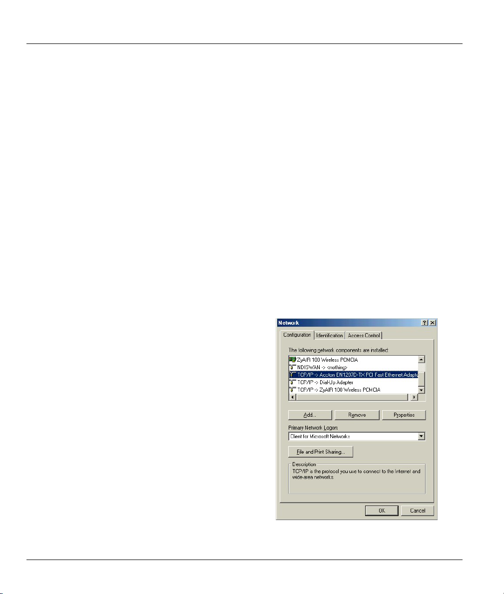
Prestige 650M ADSL Bridge
Appendix C
Setting up Your Computer’s IP Address
All computers must have a 10M or 100M Ethernet adapter card and TCP/IP installed.
Windows 95/98/Me/NT/2000/XP, Macintosh OS 7 and later operating systems and all versions of
UNIX/LINUX include the software components you need to install and use TCP/IP on your computer.
Windows 3.1 requires the purchase of a third-party TCP/IP application package.
TCP/IP should already be installed on computers using Windows NT/2000/XP, Macintosh OS 7 and later
operating systems.
After the appropriate TCP/IP components are installed, configure the TCP/IP settings in order to
"communicate" with your network.
If you manually assign IP information instead of using dynamic assignment, make sure that your computers
have IP addresses that place them in the same subnet as the Prestige's LAN port.
Windows 95/98/Me
Click Start, Settings, Control Panel and double-click the
Network icon to open the Network window.
D Setting up Your Computer’s IP Address

Prestige 650M ADSL Bridge
The Network window Configuration tab displays a list of installed components. You need a network
adapter, the TCP/IP protocol and Client for Microsoft Networks.
If you need the adapter:
In the Network window, click Add.
a.
Select Adapter and then click Add.
b.
Select the manufacturer and model of your network adapter and then click OK.
c.
If you need TCP/IP:
In the Network window, click Add.
a.
Select Protocol and then click Add.
b.
Select Microsoft from the list of manufacturers.
c.
Select TCP/IP from the list of network protocols and then click OK.
d.
If you need Client for Microsoft Networks:
Click Add.
a.
Select Client and then click Add.
b.
Select Microsoft from the list of manufacturers.
c.
Select Client for Microsoft Networks from the list of network clients and then click OK.
d.
e. Restart your computer so the changes you made take effect.
In the Network window Configuration tab, select your network adapter's TCP/IP entry and click
Properties.
Setting up Your Computer’s IP Address E
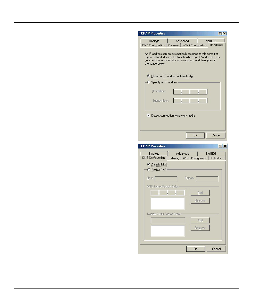
Prestige 650M ADSL Bridge
Click the IP Address tab.
1.
-If your IP address is dynamic, select Obtain an
IP address automatically.
-If you have a static IP address, select Specify
an IP address and type your information into
the IP Address and Subnet Mask fields.
Click the DNS Configuration tab.
2.
-If you do not know your DNS information, select
Disable DNS.
-If you know your DNS information, select
Enable DNS and type the information in the
fields below (you may not need to fill them all
in).
F Setting up Your Computer’s IP Address
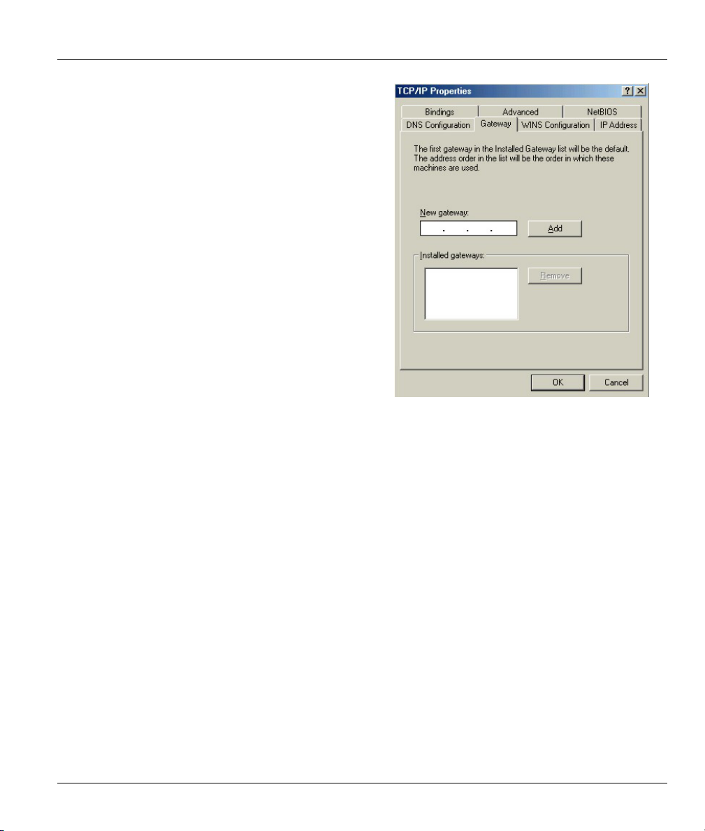
Click the Gateway tab.
3.
-If you do not know your gateway’s IP address,
remove previously installed gateways.
-If you have a gateway IP address, type it in the
New gateway field and click Add.
Click OK to save and close the TCP/IP Properties window.
4.
Click OK to close the Network window. Insert the Windows CD if prompted.
5.
Prestige 650M ADSL Bridge
6. Turn on your Prestige and restart your computer when prompted.
Verifying Your Computer’s IP Address
Click Start and then Run.
1.
In the Run window, type "winipcfg" and then click OK to open the IP Configuration window.
2.
3. Select your network adapter. You should see your computer's IP address, subnet mask and default
gateway.
Windows 2000/NT/XP
Setting up Your Computer’s IP Address G
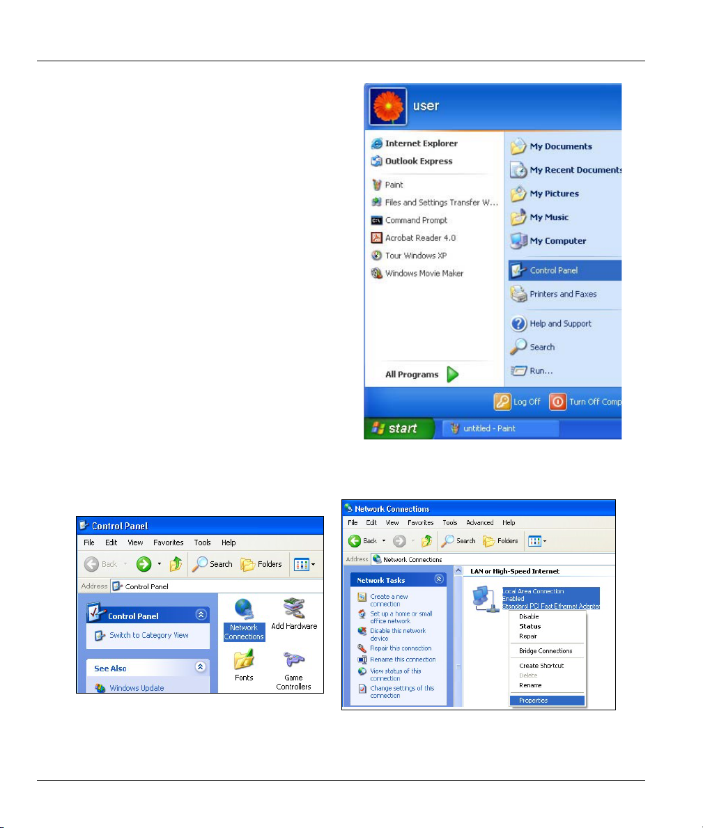
Prestige 650M ADSL Bridge
For Windows XP, click start, Control Panel. In
1.
Windows 2000/NT, click Start, Settings, Control
Panel.
For Windows XP, click Network
2.
Connections. For Windows 2000/NT, click
Network and Dial-up Connections.
Right-click Local Area Connection and
3.
then click Properties.
H Setting up Your Computer’s IP Address
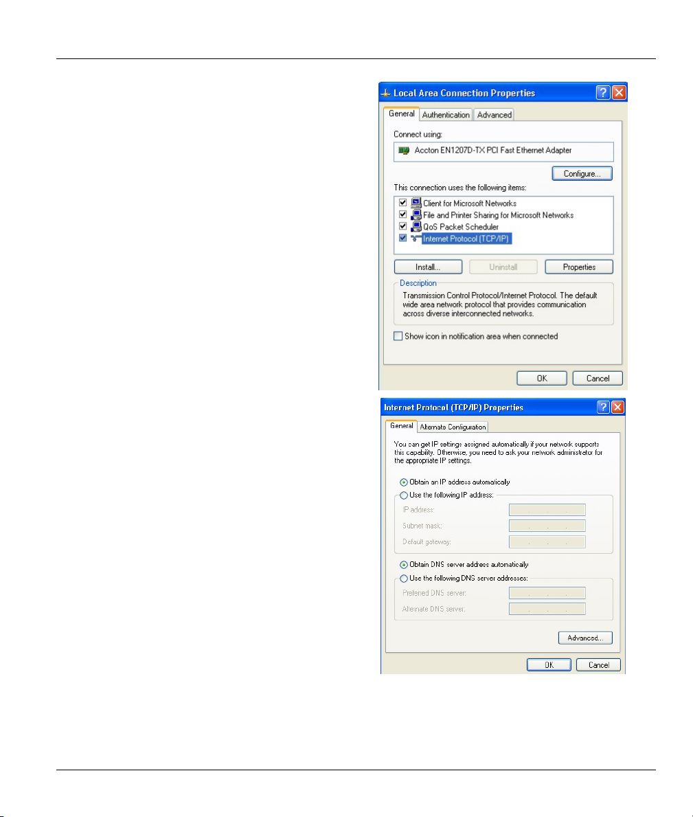
Select Internet Protocol (TCP/IP) (under the
4.
General tab in Win XP) and click Properties.
The Internet Protocol TCP/IP Properties
5.
window opens (the General tab in Windows XP).
-If you have a dynamic IP address click Obtain
an IP address automatically.
-If you have a static IP address click Use the
following IP Address and fill in the IP address,
Subnet mask, and Default gateway fields.
Click Advanced.
Prestige 650M ADSL Bridge
Setting up Your Computer’s IP Address I
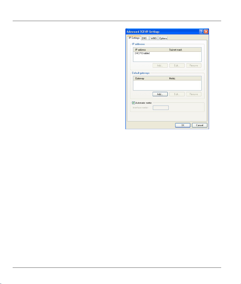
Prestige 650M ADSL Bridge
6. -If you do not know your gateway's IP address,
remove any previously installed gateways in the
IP Settings tab and click OK.
Do one or more of the following if you want to
configure additional IP addresses:
-In the IP Settings tab, in IP addresses, click
Add.
-In TCP/IP Address, type an IP address in IP
address and a subnet mask in Subnet mask,
and then click Add.
-Repeat the above two steps for each IP address
you want to add.
-Configure additional default gateways in the IP
Settings tab by clicking Add in Default
gateways.
-In TCP/IP Gateway Address, type the IP
address of the default gateway in Gateway. To
manually configure a default metric (the number
of transmission hops), clear the Automatic
metric check box and type a metric in Metric.
-Click Add.
-Repeat the previous three steps for each default gateway you want to add.
-Click OK when finished.
J Setting up Your Computer’s IP Address
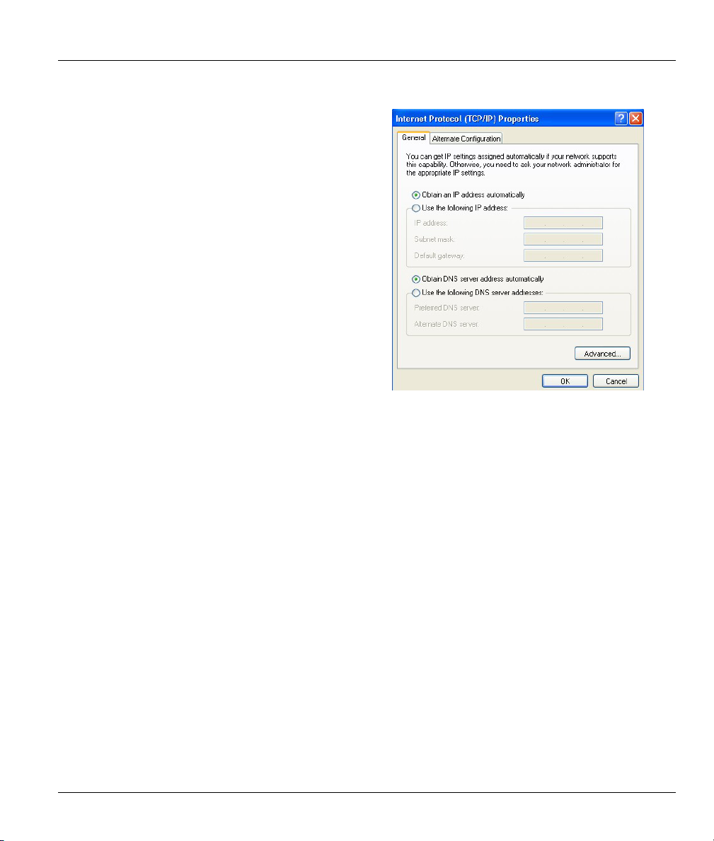
In the Internet Protocol TCP/IP Properties
7.
window (the General tab in Windows XP):
-Click Obtain DNS server address
automatically if you do not know your DNS
server IP address(es).
-If you know your DNS server IP address(es),
click Use the following DNS server addresses,
and type them in the Preferred DNS server and
Alternate DNS server fields.
If you have previously configured DNS servers,
click Advanced and then the DNS tab to order
them.
Click OK to close the Internet Protocol (TCP/IP) Properties window.
8.
Click OK to close the Local Area Connection Properties window.
9.
10. Turn on your Prestige and restart your computer (if prompted).
Prestige 650M ADSL Bridge
Verifying Your Computer’s IP Address
Click Start, All Programs, Accessories and then Command Prompt.
1.
In the Command Prompt window, type "ipconfig" and then press [ENTER]. You can also open
2.
Network Connections, right-click a network connection, click Status and then click the Support tab.
Macintosh OS 8/9
Setting up Your Computer’s IP Address K
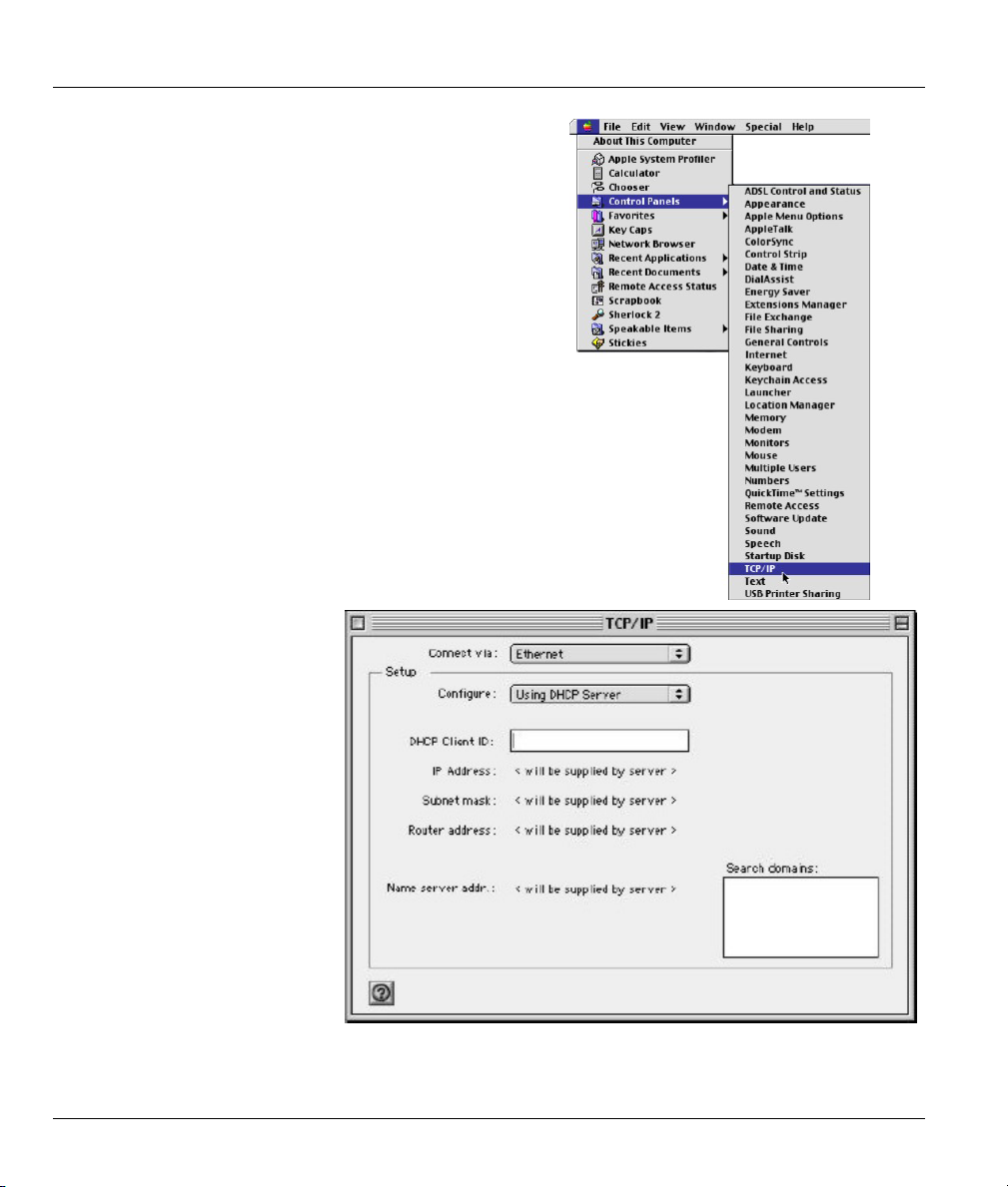
Prestige 650M ADSL Bridge
Click the Apple menu, Control Panel and double-click
1.
TCP/IP to open the TCP/IP Control Panel.
Select Ethernet built-in
2.
from the Connect via list.
For dynamically assigned settings, select Using DHCP Server from the Configure: list.
3.
L Setting up Your Computer’s IP Address
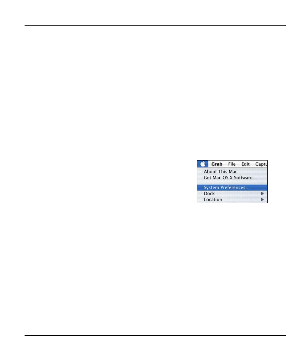
4. For statically assigned settings, do the following:
-From the Configure box, select Manually.
-Type your IP address in the IP Address box.
-Type your subnet mask in the Subnet mask box.
-Type the IP address of your Prestige in the Router address box.
Close the TCP/IP Control Panel.
5.
Click Save if prompted, to save changes to your configuration.
6.
7. Turn on your Prestige and restart your computer (if prompted).
Verifying Your Computer’s IP Address
Check your TCP/IP properties in the TCP/IP Control Panel window.
Macintosh OS X
Click the Apple menu, and click System Preferences
1.
to open the System Preferences window.
Prestige 650M ADSL Bridge
Setting up Your Computer’s IP Address M

Prestige 650M ADSL Bridge
2.
Click Network in the icon bar.
- Select Automatic from the Location list.
- Select Built-in Ethernet from the Show list.
- Click the TCP/IP tab.
3.
For dynamically assigned settings, select Using DHCP from the Configure list.
4. For statically assigned settings, do the following:
-From the Configure box, select Manually.
-Type your IP address in the IP Address box.
-Type your subnet mask in the Subnet mask box.
-Type the IP address of your Prestige in the Router address box.
Click Apply Now and close the window.
5.
6. Turn on your Prestige and restart your computer (if prompted).
Verifying Your Computer’s IP Address
Check your TCP/IP properties in the Network window.
N Setting up Your Computer’s IP Address

Index
A
ADSL, what is it?............................................. xv
Authentication................................................. 5-3
Auto-Negotiation ............................................1-1
B
Back Panel
Connections Description ............................. 2-2
Backup ............................................................ 8-2
C
CHAP.............................................................. 5-3
Collision.......................................................... 7-2
Command Interpreter Mode............................ 7-6
Command Mode..............................................7-7
Computer’s IP Address ..................................... D
Connections
ADSL Line.................................................. 2-2
Power Adapter ............................................2-3
Console Port Speed......................................... 7-3
Copyright ........................................................... ii
CPU Load........................................................7-3
Customer Support .............................................. v
D
F
FCC................................................................... iii
Filename Conventions .................................... 8-1
Filter ............................................................... 6-1
Applying Filters.......................................... 6-7
Example...................................................... 6-6
Filter Rules ................................................. 6-4
Generic Filter Rule ..................................... 6-5
Remote Node Filters ................................... 6-7
Filter Rule Process.......................................... 6-2
Filter Rule Setup............................................. 6-4
Filter Rules Summary
Sample ........................................................ 6-7
Filter Set Configuration .................................. 6-3
Filtering .......................................................... 6-1
Frame Relay.................................................... 1-3
FTP File Transfer............................................ 8-8
G
General Setup ................................................. 3-6
H
Hidden Menus................................................. 3-3
I
DHCP.............................................................. 7-4
Diagnostic ....................................................... 7-5
Digital Subscriber Line Access Multiplexer ... 1-3
DSL (Digital Subscriber Line)......................... xv
DSL, what is it?................................................ xv
DSLAM ....... See Digital Subscriber Line Access
Multiplexer
E
Encapsulation................................... 1-2, 4-2, 4-5
PPPoA......................................................... 4-2
RFC 1483.................................................... 4-2
Ethernet Bridge ............................................... xiii
Index O
IANA .............................................................. 3-7
Initialization.................................................... 3-1
Internet Access.....xiii, 1-1, 1-3, 3-4, 4-1, 4-4, 4-5
IP Address................................................ 3-8, 7-4
IP Network Number........................................ 3-7
IP Packet......................................................... 6-4
L
LAN......................................................... 7-2, 7-3
Link type......................................................... 7-2
Logging Option............................................... 6-6
Login............................................................... 5-2

M
Main Menu ..................................................... 3-3
MBS (Maximum Burst Size) .................. 4-3, 4-5.
Multiplexing
LLC-based .................................................. 4-2
VC-based .................................................... 4-2
Multiplexing .....................................1-2, 4-2, 4-5
Multiprotocol Encapsulation........................... 4-2
N
Network Management .................................... 1-2
NIC ................................................................. 2-3
P
Packet
Error............................................................ 7-2
Received ..................................................... 7-3
Transmitted................................................. 7-3
Packets............................................................ 7-2
PAP................................................................. 5-3
Password............................ 2-3, 3-1, 3-4, 5-2, 5-3
Point-to-Point....................................................xv
PPPoA............................................................. 4-3
PVC Connection
Fail.............................................................. 9-2
RFC-2364 ................................................ 4-3, 5-2
S
SCR See Sustain Cell Rate. See Sustain Cell Rate
Service...............................................................iv
Splitters............................................................2-4
STP..................................................................2-3
Subnet Mask..................................... 3-7, 3-8, 7-4
Support Disk....................................................xiii
Syntax Conventions.........................................xiv
System
Console Port Speed......................................7-5
Diagnostic....................................................7-5
System Information .....................................7-4
System Status ..............................................7-1
System Information .........................................7-3
System Information and Diagnosis..................7-1
System Maintenance. 7-1, 7-3, 7-6, 8-2, 8-5, 8-10
System Management Terminal........................3-2
T
TFTP File Transfer........................................8-10
To avoid damage to the Prestige......................2-3
Transmission Rates.................................. xiii, 1-1
U
R
RAS ................................................................ 7-4
Rate
Receiving .................................................... 7-2
Transmission............................................... 7-2
Related Documentation................................... xiii
Remote Node ........................................... 5-1, 7-2
Remote Node Index Number ...................... 7-2
Remote Node Setup ............................. 5-1, 5-2
Remote Node Traffic ...................................... 6-8
Required fields................................................ 3-3
RESET Button ................................................ 2-3
Restore Configuration..................................... 8-6
RFC-1483 ....................................................... 4-3
Upload Firmware.............................................8-8
V
VC-based Multiplexing ...................................4-3
VPI and VCI....................................................4-1
X
XMODEM Protocol ........................................8-2
Z
ZyNOS ............................................................8-2
ZyNOS F/W Version.......................................8-2
ZyXEL Limited Warranty
Note ...............................................................iv
P Index
 Loading...