


Prestige 642M Series
ADSL Bridge
User's Guide
Version 2.50
February 2001

Prestige 642M Series ADSL Bridge
Copyright
Copyright ©2000 by ZyXEL Communications Corporation.
The contents of this publication may not be reproduced in any part or as a whole, transcribed, stored in a
retrieval system, translated into any language, or transmitted in any form or by any means, electronic,
mechanical, magnetic, optical, chemical, photocopying, manual, or otherwise, without the prior written
permission of ZyXEL Communications Corporation.
Published by ZyXEL Communications Corporation. All rights reserved.
Disclaimer
ZyXEL does not assume any liability arising out of the application or use of any products, or software
described herein. Neither does it convey any license under its patent rights nor the patents' rights of others.
ZyXEL further reserves the right to make changes in any products described herein without notice. This
publication is subject to change without notice.
Trademarks
Trademarks mentioned in this publication are used for identification purposes only and may be properties of
their respective owners. ZyNOS is a registered trademark of ZyXEL Communications Corporation.
ii Copyright

Prestige 642M Series ADSL Bridge
FCC iii

Prestige 642M Series ADSL Bridge
iv CE

Prestige 642M Series ADSL Bridge
ZyXEL Limited Warranty
ZyXEL warrants to the original end user (purchaser) that this product is free from any defects in materials
or workmanship for a period of up to two (2) years from the date of purchase. During the warranty period
and upon proof of purchase, should the product have indications of failure due to faulty workmanship
and/or materials, ZyXEL will, at its discretion, repair or replace the defective products or components
without charge for either parts or labor and to whatever extent it shall deem necessary to restore the product
or components to proper operating condition. Any replacement will consist of a new or re-manufactured
functionally equivalent product of equal value, and will be solely at the discretion of ZyXEL. This warranty
shall not apply if the product is modified, misused, tampered with, damaged by an act of God, or subjected
to abnormal working conditions.
Note
Repair or replacement, as provided under this warranty, is the exclusive remedy of the purchaser. This
warranty is in lieu of all other warranties, express or implied, including any implied warranty of
merchantability or fitness for a particular use or purpose. ZyXEL shall in no event be held liable for indirect
or consequential damages of any kind of character to the purchaser.
To obtain the services of this warranty, contact ZyXEL's Service Center for your Return Material
Authorization number (RMA). Products must be returned Postage Prepaid. It is recommended that the unit
be insured when shipped. Any returned products without proof of purchase or those with an out-dated
warranty will be repaired or replaced (at the discretion of ZyXEL) and the customer will be billed for parts
and labor. All repaired or replaced products will be shipped by ZyXEL to the corresponding return address,
Postage Paid. This warranty gives you specific legal rights, and you may also have other rights that vary
from country to country.
Online Registration
Don’t forget to register your ZyXEL product (fast, easy online registration at
www.zyxel.com) for free future product updates and information.
ZyXEL Limited Warranty v
Prestige 642M Series ADSL Bridge
Customer Support
When you contact your customer support representative have the following information ready:
♦ Prestige Model and serial number.
♦ Information in Menu 24.2.1 –System Information.
♦ Warranty Information.
♦ Date you received your Prestige.
♦ Brief description of the problem and the steps you took to solve it.
METHOD
REGION
WORLDWIDE
NORTH
AMERIC A
SCANDINAVIA
AUSTRIA
GERMANY
EMAIL – SUPPORT
EMAIL – SALES
support@zyxel.com.tw
support@europe.zyxel.com
sales@zyxel.com.tw
support@zyxel.com +1-714-632-0882
sales@zyxel.com
support@zyxel.dk
sales@zyxel.dk
support@zyxel.at
sales@zyxel.at +43-1-4948678 ftp.zyxel.at
support@zyxel.de
sales@zyxel.de
TELEPHONE WEB SITE
FAX FTP SITE
+886-3-578-3942 www.zyxel.com
+886-3-578-2439
800-255-4101
+1-714-632-0858
+45-3955-0700
+45-3955-0707
+43-1-4948677-0
0810-1-ZyXEL
0810-1-99935
+49-2405-6909-0
0180-5213247
Tech Support
hotline
0180-5099935
RMA/Repair
hotline
+49-2405-690999
www.europe.zyxel.com
ftp.europe.zyxel.com
www.zyxel.com
ftp.zyxel.com
www.zyxel.dk
ftp.zyxel.dk
www.zyxel.at
NOTE:
for Austrian
users with *.at domain
only!
www.zyxel.de
ftp.europe.zyxel.com
REGULAR MAIL
Communications
Corp., 6 Innovation
Road II, Science-
Based Industrial Park,
HsinChu, Taiwan.
Communications Inc.,
1650 Miraloma
Avenue, Placentia, CA
92870, U.S.A.
Communications A/S,
Columbusvej 5, 2860
Soeborg, Denmark.
Communications
Services GmbH.,
Thaliastrasse
125a/2/2/4, A-1160
Vienna, Austria.
ZyXEL Deutschland
GmbH., Adenauerstr.
20/A4, D-52146
Wuerselen, Germany.
ZyXEL
ZyXEL
ZyXEL
ZyXEL
vi Customer Support

Prestige 642M Series ADSL Bridge
Table of Contents
Copyright......................................................................................................................................................................... ii
Warranty ...........................................................................................................................................................................v
List of Figures ..................................................................................................................................................................x
List of Tables................................................................................................................................................................. xii
Preface .......................................................................................................................................................................... xiii
Structure of this Manual .............................................................................................................................................. xiv
What is ADSL? ..............................................................................................................................................................xv
Chapter 1 Getting to Know Your ADSL Bridge....................................................................................................... 1-1
1.1 The Prestige 642M Series ADSL Bridge ........................................................................................1-1
1.2 Features of the Prestige 642M Series..............................................................................................1-1
1.3 Applications for the Prestige 642M.................................................................................................1-2
1.3.1 Internet Access .......................................................................................................................1-2
1.3.2 LAN to LAN Application.......................................................................................................1-2
Chapter 2 Hardware Installation & Initial Setup....................................................................................................... 2-1
2.1 Front Panel LEDs of the P642M....................................................................................................2-1
2.2 Rear Panel and Connections of the P642M.....................................................................................2-1
2.3 Additional Installation Requirements..............................................................................................2-2
2.4 Connecting a POTS Splitter ............................................................................................................2-2
2.5 Telephone Microfilters....................................................................................................................2-3
2.6 Special Note for P642M ISDN Users..............................................................................................2-4
2.7 Power Up Your Prestige..................................................................................................................2-5
2.7.1 Prestige 642M SMT Menu Overview.....................................................................................2-6
2.8 Navigating the SMT Interface.........................................................................................................2-7
2.8.1 System Management Terminal Interface Summary ...............................................................2-8
2.9 Changing the System Password ......................................................................................................2-8
2.10 General Setup..............................................................................................................................2-9
Chapter 3 Internet Access ........................................................................................................................................... 3-1
Table of Contents vii

Prestige 642M Series ADSL Bridge
3.1 Factory Ethernet Defaults ...............................................................................................................3-1
3.2 TCP/IP Parameters..........................................................................................................................3-1
3.2.1 IP Address and Subnet Mask..................................................................................................3-1
3.2.2 Private IP Addresses............................................................................................................... 3-1
3.3 TCP/IP Ethernet Setup....................................................................................................................3-2
3.4 LANs & WANs...............................................................................................................................3-3
3.4.1 LANs, WANs and the Prestige............................................................................................... 3-3
3.5 VPI & VCI......................................................................................................................................3-4
3.6 Multiplexing....................................................................................................................................3-4
3.6.1 VC-based multiplexing .......................................................................................................... 3-4
3.6.2 LLC-based multiplexing ........................................................................................................3-4
3.7 Encapsulation..................................................................................................................................3-4
3.7.1 PPP......................................................................................................................................... 3-4
3.7.2 RFC 1483 ............................................................................................................................... 3-4
3.8 Internet Access Configuration.........................................................................................................3-4
Chapter 4 Remote Node Configuration ......................................................................................................................4-1
4.1 Remote Node Setup ........................................................................................................................4-1
4.1.1 Remote Node Profile.............................................................................................................. 4-1
4.1.2 Encapsulation & Multiplexing Scenarios............................................................................... 4-1
Chapter 5 Filter Configuration .................................................................................................................................... 5-1
5.1 About Filtering................................................................................................................................5-1
5.2 Configuring a Filter Set...................................................................................................................5-3
5.2.1 Filter Rules Summary Menu ..................................................................................................5-4
5.3 Configuring a Filter Rule................................................................................................................5-5
5.3.1 Generic Filter Rule................................................................................................................. 5-5
5.4 Example Filter.................................................................................................................................5-7
5.5 Applying a Filter.............................................................................................................................5-9
5.5.1 Remote Node Filters............................................................................................................... 5-9
Chapter 6 System Maintenance...................................................................................................................................6-1
6.1 System Status..................................................................................................................................6-1
6.2 System Information and Console Port Speed..................................................................................6-3
6.2.1 System Information................................................................................................................ 6-4
6.2.2 Console Port Speed ................................................................................................................ 6-5
viii Table of Contents

Prestige 642M Series ADSL Bridge
6.3 Diagnostic .......................................................................................................................................6-5
6.4 A Note about Filenames..................................................................................................................6-6
6.4.1 Firmware Development .......................................................................................................... 6-8
6.5 Backup Configuration .....................................................................................................................6-8
6.5.1 Backup using the Console Port...............................................................................................6-8
Backup using FTP ...............................................................................................................................6-9
6.5.3 Backup using TFTP................................................................................................................6-9
6.6 Restore Configuration ...................................................................................................................6-10
6.6.1 Restore using the Console Port.............................................................................................6-10
6.6.2 Restore using FTP ................................................................................................................6-11
6.6.3 Restore using TFTP..............................................................................................................6-12
6.7 Upload Firmware...........................................................................................................................6-12
6.7.1 Upload System Firmware via the Console Port....................................................................6-13
6.7.2 Upload System Firmware using FTP....................................................................................6-14
Using the FTP Command from the DOS Prompt .............................................................................. 6-14
6.7.3 Upload System Firmware using TFTP .................................................................................6-15
6.8 Upload System Configuration File................................................................................................6-16
6.8.1 Upload System Configuration File using the Console Port.................................................. 6-16
6.8.2 Upload System Configuration File using FTP......................................................................6-17
6.8.3 Upload System Configuration File using TFTP ................................................................... 6-18
6.9 Command Interpreter Mode..........................................................................................................6-18
6.10 Boot module commands ...........................................................................................................6-19
Chapter 7 Troubleshooting.......................................................................................................................................... 7-1
7.1 Problems Starting Up the Prestige...................................................................................................7-1
7.2 Problems With the WAN Interface .................................................................................................7-1
7.3 Problems with the LAN Interface ...................................................................................................7-2
7.4 Problems Connecting to a Remote Node or ISP .............................................................................7-2
Glossary ...........................................................................................................................................................................A
Appendix A VPI & VCI.................................................................................................................................................G
Appendix B Configure Your PPPoE Modem...............................................................................................................H
Appendix C Configure Your Computer for PPPoE ......................................................................................................J
Index ...............................................................................................................................................................................M
Table of Contents ix

Prestige 642M Series ADSL Bridge
List of Figures
Figure 1-1 Internet Access Application .......................................................................................................1-2
Figure 1-2 LAN-to-LAN Application..........................................................................................................1-3
Figure 2-1 Front Panel of the P642M...........................................................................................................2-1
Figure 2-2 Rear Panel and Connections of the P642M................................................................................2-1
Figure 2-3 Connecting a POTS Splitter .......................................................................................................2-3
Figure 2-4 Connecting a Microfilter ............................................................................................................2-4
Figure 2-5 P642M with ISDN......................................................................................................................2-4
Figure 2-6 Power-On Display ......................................................................................................................2-5
Figure 2-7 Login Screen...............................................................................................................................2-5
Figure 2-8 Prestige 642M SMT Menu Overview.........................................................................................2-6
Figure 2-9 SMT Main Menu........................................................................................................................2-8
Figure 2-10 Menu 23.1 - System Password .................................................................................................2-9
Figure 2-11 Menu 1 - General Setup............................................................................................................2-9
Figure 3-1 Menu 3 - TCP/IP Ethernet Setup................................................................................................3-2
Figure 3-2 LAN & WAN.............................................................................................................................3-3
Figure 3-3 Internet Access Setup .................................................................................................................3-5
Figure 4-1 Menu 11- Remote Node Setup ...................................................................................................4-1
Figure 4-2 Menu 11.1 - Remote Node Profile..............................................................................................4-2
Figure 5-1 Filter Rule Process......................................................................................................................5-2
Figure 5-2 Menu 21 - Filter Set Configuration ............................................................................................5-3
Figure 5-3 Filter Rules Summary.................................................................................................................5-4
Figure 5-4 Menu 21.1.2 - Generic Filter Rule..............................................................................................5-6
Figure 5-5 Example Filter - Menu 21.1.1.....................................................................................................5-8
Figure 5-6 Example Filter Rules Summary - Menu 21.1.............................................................................5-9
Figure 5-7 Filtering Remote Node Traffic ................................................................................................. 5-10
Figure 6-1 Menu 24 - System Maintenance.................................................................................................6-1
Figure 6-2 Menu 24.1 - System Maintenance - Status.................................................................................6-2
Figure 6-3 System Information and Console Port Speed.............................................................................6-4
Figure 6-4 System Maintenance - Information ............................................................................................6-4
Figure 6-5 Menu 24.2.2 - System Maintenance - Console Port Speed ........................................................6-5
Figure 6-6 Menu 24.4 - System Maintenance - Diagnostic..........................................................................6-5
Figure 6-7 External and Internal Filenames.................................................................................................6-7
Figure 6-8 Menu 24.5 - Menu 24.5 as seen using the Console Port.............................................................6-8
Figure 6-9 Backup Example Using HyperTerminal.....................................................................................6-8
Figure 6-10 Successful Backup Confirmation Screen..................................................................................6-9
Figure 6-11 FTP Session Example as seen Using Telnet.............................................................................6-9
Figure 6-12 Menu 24.6 as seen using the Console Port .............................................................................6-10
Figure 6-13 Restore Example Using HyperTerminal.................................................................................6-11
Figure 6-14 Successful Restoration Confirmation Screen .........................................................................6-11
x List of Figures

Prestige 642M Series ADSL Bridge
Figure 6-15 Menu 24.6 as seen using Telnet..............................................................................................6-11
Figure 6-16 Menu 24.7 - System Maintenance - Upload Firmware...........................................................6-12
Figure 6-17 Menu 24.7.1 as seen using the Console Port. .........................................................................6-13
Figure 6-18 Upload BIN File Example Using HyperTerminal ..................................................................6-13
Figure 6-19 Menu 24.7.1 as seen using Telnet...........................................................................................6-14
Figure 6-20 FTP Session Example.............................................................................................................6-14
Figure 6-21 Menu 24.7.2 as seen using the Console Port ..........................................................................6-16
Figure 6-22 Upload ROM File Example Using HyperTerminal................................................................6-17
Figure 6-23 Menu 24.7.2 as seen using Telnet...........................................................................................6-17
Figure 6-24 Command mode......................................................................................................................6-18
Figure 6-25 Boot module commands .........................................................................................................6-20
List of Figures xi

Prestige 642M Series ADSL Bridge
List of Tables
Table 2-1 Front Panel LED Description ......................................................................................................2-1
Table 2-2 Main Menu Commands ...............................................................................................................2-7
Table 2-3 Main Menu Summary..................................................................................................................2-8
Table 2-4 General Setup Menu Fields........................................................................................................2-10
Table 3-1 TCP/IP Ethernet Setup Menu Fields............................................................................................3-2
Table 3-2 Internet Account Information ......................................................................................................3-5
Table 3-3 Internet Access Setup Menu Fields..............................................................................................3-6
Table 4-1 Remote Node Profile Menu Fields ..............................................................................................4-3
Table 5-1 Abbreviations Used in the Filter Rules Summary Menu ............................................................. 5-4
Table 5-2 Abbreviations Used If Filter Type is GEN ..................................................................................5-5
Table 5-3 Generic Filter Rule Menu Fields..................................................................................................5-6
Table 6-1 System Maintenance - Status Menu Fields..................................................................................6-3
Table 6-2 Fields in System Maintenance - Information...............................................................................6-4
Table 6-3 System Maintenance Menu Diagnostic .......................................................................................6-6
Table 6-4 Filenames.....................................................................................................................................6-7
Table 6-5 Third Party TFTP Clients - General fields.................................................................................6-15
Table 7-1 Troubleshooting the Start-Up of your Prestige ............................................................................ 7-1
Table 7-2 Troubleshooting the ADSL connection ....................................................................................... 7-1
Table 7-3 Troubleshooting the LAN Interface.............................................................................................7-2
Table 7-4 Troubleshooting a Connection to a Remote Node or ISP ............................................................ 7-2
xii List of Tables

Prestige 642M Series ADSL Bridge
Preface
About Your ADSL Bridge
Congratulations on your purchase of the Prestige 642M Series ADSL Bridge.
The Prestige 642M is an ADSL bridge used for Internet access via an ADSL line. It can run upstream
maximum rate at 640kbps and downstream rate at 8Mbps. The rate selection depends on the copper
category, distance and central side configuration. We will refer to the Prestige 642M as the P642 or simply
the Prestige from now on.
The P642's 10/100M auto-negotiating LAN interface enables fast data transfer of either 10Mbps or
100Mbps in either half-duplex or full-duplex mode depending on your Ethernet network.
Your Prestige is easy to install and configure. All functions of the Prestige are software configurable via the
SMT (System Management Terminal) Interface. PPPoE Modem firmware for your P642M will be
available by October 2000.
About This Guide
This guide covers all aspects of the Prestige 642 operations and shows you how to get the best out of the
multiple advanced features of your ADSL Internet Access Router using the SMT. It is designed to guide
you through the correct configuration of your Prestige 642 for various applications.
Syntax Conventions
• “Enter” means for you to type one or more characters and press the carriage return. “Select” or
“Choose” means for you to select one from the predefined choices.
• The SMT menu titles and labels are in Bold Times font. The choices of a menu item are in Bold Arial
font. A single keystroke is in Arial font and enclosed in square brackets, for instance, [ENTER] means
the Enter, or carriage return key; [ESC] means the Escape key.
• For brevity’s sake, we will use “e.g.” as a shorthand for “for instance”, and “i.e.” as a shorthand for
“that is” or “in other words” throughout this manual.
Preface xiii
Prestige 642M Series ADSL Bridge
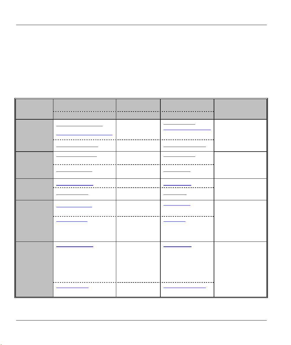
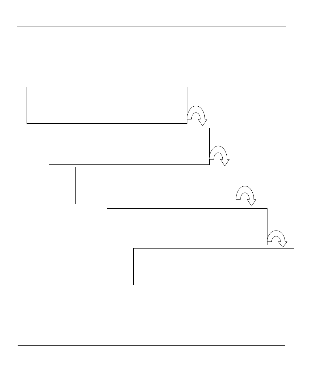
Structure of this Manual
The following section offers some background information on ADSL. Skip to Chapter 1 if you wish to
begin working with your router right away.
Getting Started (Chapters 1-2)
This helps you connect, install and setup your Prestige to
operate on your network.
The Internet (Chapter 3)
This shows you how to configure your Prestige for Internet
access.
Remote Node (Chapters 4)
This shows you how to configure the remote nodes.
Management & Maintenance (Chapters 5-6)
This shows you how to create/apply filters and manage/maintain
your system.
Troubleshooting (Chapter 7)
This provides information about solving common problems
xiv Structure of this Manual
.

Prestige 642M Series ADSL Bridge
What is DSL?
DSL (Digital Subscriber Line) enhances the data capacity of the existing twisted-pair wire that runs
between the local telephone company switching offices, most homes and offices. While the wire itself can
handle higher frequencies, the telephone switching equipment is designed to cut off signals above 4,000 Hz
to filter noise off the voice line. Now, however, everybody is searching for ways to get more bandwidth to
improve access to the Web - hence DSL technologies!
There are actually seven types of DSL service, ranging in speeds from 16 Kbits/sec to 52 Mbits/sec. The
services are either symmetrical (traffic flows at the same speed in both directions), or asymmetrical (the
downstream capacity is higher than the upstream capacity). Asymmetrical services (ADSL) are suitable for
Internet users because more information is usually downloaded than uploaded. For example, a simple
button click in a web browser can start an extended download that includes graphics and text.
As data rates increase, the carrying distance decreases. In other words, if your computer is beyond a certain
distance, from the central office of a telephone company, then you may not be able to obtain the higher
speeds. A DSL connection is a point-to-point dedicated circuit, meaning that the link is always up and that
there is no dialing required.
What is ADSL?
It is an asymmetrical technology, meaning that the downstream data rate is much higher than the upstream
data rate. As mentioned, this works well for a typical Internet session in which more information is
downloaded, e.g., from Web servers, than is uploaded. ADSL operates in a frequency range that is above
the frequency range of voice services, so the two systems can operate over the same cable.
What is DSL? xv


Prestige 642M Series ADSL Bridge
Chapter 1
Getting to Know Your ADSL Bridge
This chapter describes the key features and applications of the Prestige 642M.
1.1 The Prestige 642M Series ADSL Bridge
Your Prestige integrates a high-speed 10/100Mbps LAN interface and one high-speed ADSL port into a
single package. The Prestige is ideal for high-speed Internet browsing and making LAN-to-LAN
connections to remote networks.
1.2 Features of the Prestige 642M Series
Your Prestige is packed with a number of features that give it the flexibility to provide a complete
networking solution for almost anyone.
z Ease of Installation
Your Prestige is designed for quick, intuitive and easy installation. Your Prestige weighs very little and is
extremely compact making it easy to position anywhere in your busy office.
z High Speed Internet Access
The Prestige can support downstream transmission rates of up to 8Mbps and upstream transmission rates of
832 Kbps. The Prestige also supports rate management. Rate management allows ADSL subscribers to
select an Internet access speed that best suit their needs and budget.
z 10/100Mbps Fast Ethernet LAN Interface
The Prestige's 10/100M auto-negotiating LAN interface enables fast data transfer of either 10Mbps or
100Mbps, in either half-duplex or full-duplex mode, depending on your Ethernet network.
z Protocols Supported
PPP (Point-to-Point Protocol) Bridge link layer protocol.
Transparently bridging for unsupported network layer protocols.
z Networking Compatibility
Your Prestige is compatible with the major ADSL DSLAM (Digital Subscriber Line Access Multiplexer)
providers making configuration extremely simple.
z Multiplexing
The Prestige supports VC-based and LLC-based multiplexing.
z Encapsulation
The Prestige supports PPP (RFC 2364 - PPP over ATM Adaptation Layer 5) and RFC 1483 encapsulation
over ATM.
z Full Network Management
♦ Access SMT (System Management Terminal) through a telnet connection.
Getting to Know Your ADSL Bridge 1-1
Prestige 642M Series ADSL Bridge
z PAP and CHAP Security
The Prestige supports PAP (Password Authentication Protocol) and CHAP (Challenge Handshake
Authentication Protocol). CHAP is more secure than PAP because the password is scrambled prior to
transmission. PAP, on the other hand, is readily available on more platforms.
z Filters
The Prestige has filtering functions that allow added network security and management.
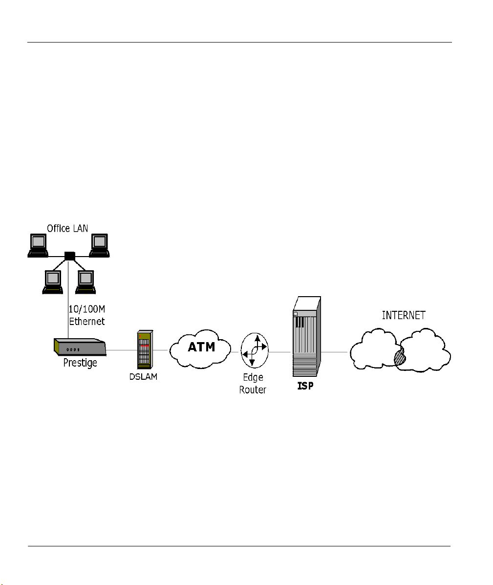
1.3 Applications for the Prestige 642M
1.3.1 Internet Access
The Prestige is the ideal high-speed Internet access solution. Your Prestige supports the TCP/IP protocol,
which the Internet uses exclusively. It is compatible with all major ADSL DSLAM (Digital Subscriber
Line Access Multiplexer) providers. A DSLAM is a rack of ADSL line cards with data multiplexed into a
backbone network interface/connection (e.g., T1, OC3, DS3, ATM or Frame Relay). Think of it as the
equivalent of a modem rack for ADSL. A typical Internet Access application is shown below.
Figure 1-1 Internet Access Application
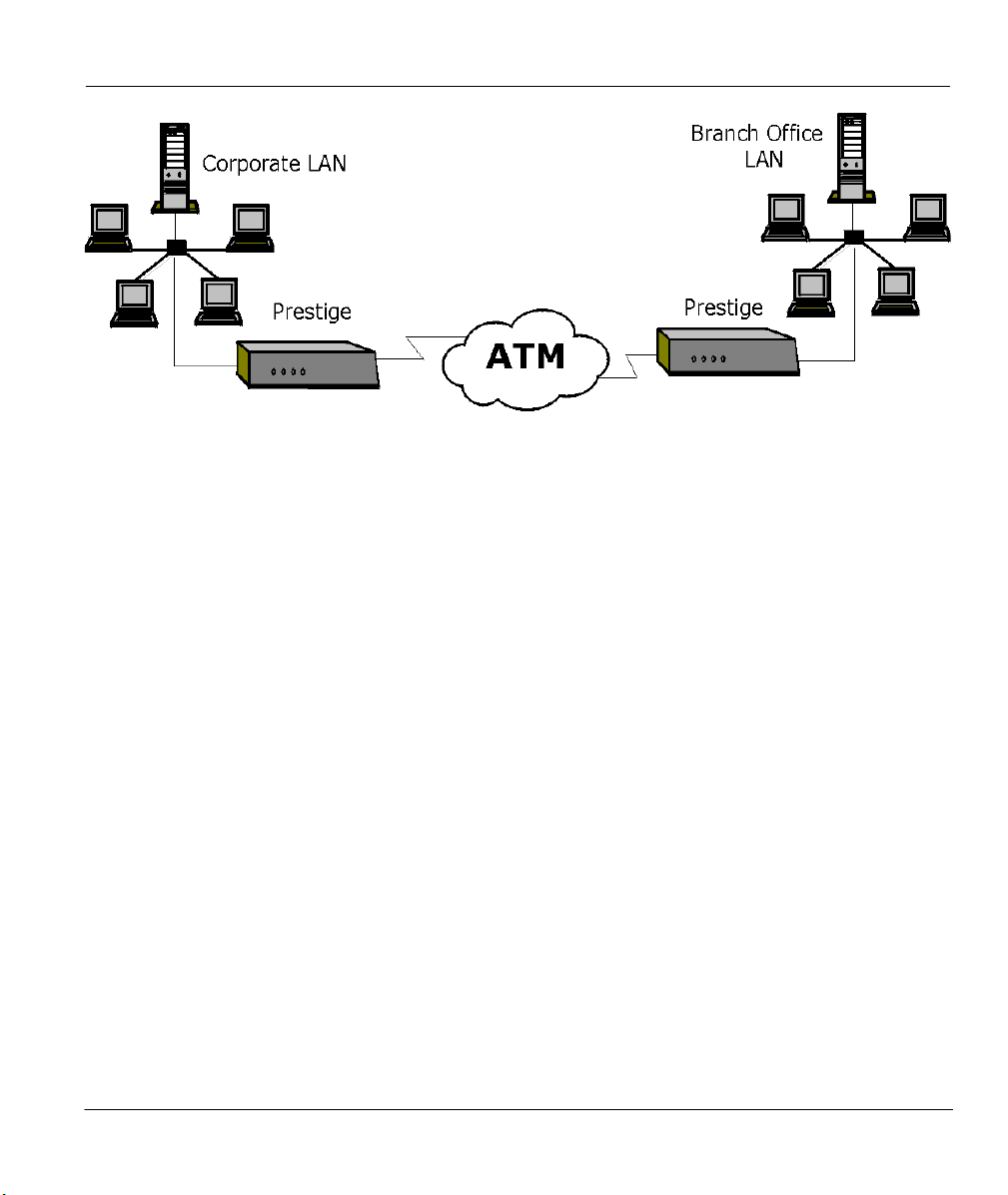
1.3.2 LAN to LAN Application
You can use the Prestige to connect two geographically dispersed networks over the ADSL line. A typical
LAN-to-LAN application for your Prestige is shown as follows.
1-2 Getting to Know Your ADSL Bridge
Prestige 642M Series ADSL Bridge
Figure 1-2 LAN-to-LAN Application
Getting to Know Your ADSL Bridge 1-3

Prestige 642M Series ADSL Bridge
Chapter 2
Hardware Installation & Initial Setup
This chapter describes the physical features of the Prestige
and how to make the cable connections
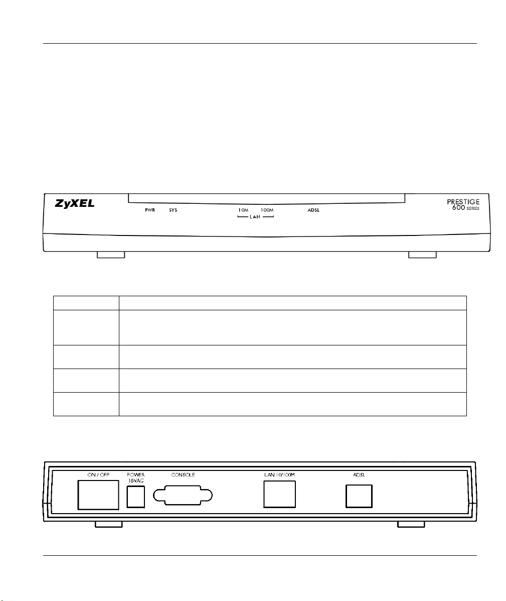
2.1 Front Panel LEDs of the P642M
The LED indicators on the front panel indicate the operational status of the Prestige. The table below the
figure describes the LED functions:
Figure 2-1 Front Panel of the P642M
Table 2-1 Front Panel LED Description
PWR
SYS
LAN 10M
LAN 100M
ADSL
The PWR (power) LED is on when power is applied to the Prestige.
A steady on SYS (system) LED indicates the Prestige is on and functioning
properly while an off SYS LED indicates that the system is not ready or has
malfunctioned. The system is rebooting when the SYS LED is blinking.
A steady light indicates a 10Mb Ethernet connection. The LED will blink when
data is sent/received.
A steady light indicates a 100Mb Ethernet connection. The LED will blink when
data is sent/received.
The ADSL LED is on when the Prestige is connected successfully to a DSLAM.
The LED blinks when data is sent/received. The LED is off when the link is down.
.
2.2 Rear Panel and Connections of the P642M
The following figure shows the rear panel connectors of your Prestige.
Figure 2-2 Rear Panel and Connections of the P642M
Hardware Installation & Initial Setup 2-1

Prestige 642M Series ADSL Bridge
Step 1.
Connect the Prestige directly to the wall jack using the included ADSL cable. Connect a microfilter(s) (see
Figure 2-4 Connecting a Microfilter) between the wall jack and your telephone(s). Microfilter(s) act as low
pass filters (voice transmission takes place in the 0 to 4KHz bandwidth). A Mircrofilter is an optional
purchase.
Step 2.
Ethernet 10Base-T/100Base-T networks use Shielded Twisted Pair (STP) cable with RJ-45 connectors that
look like a bigger telephone plug with 8 pins. Use the crossover cable (red tag) to connect your Prestige to a
computer directly. Use straight through Ethernet cable (white tag) to connect to an external hub and then
connect one end of a straight through Ethernet cable (white tag) from the hub to the NIC on the workstation.
Connecting the ADSL Line
Connecting a Workstation to the Prestige 10/100M LAN port
Step 3. Connecting the Power Adapter to your Prestige
Connect the power adapter to the port labeled POWER on the rear panel of your Prestige.
Step 4.
For the initial configuration of your Prestige, you need to use terminal emulator software on a workstation
and connect it to the Prestige through the console port. Connect the 9-pin end of the console cable (9-pin to
25-pin console cable supplied) to the console port of the Prestige and the 25-pin end to a serial port (COM1,
COM2 or other COM port) of your workstation. You can use an extension RS-232 cable if the enclosed
one is too short.
Connecting the Console Port
2.3 Additional Installation Requirements
In addition to the contents of your package, there are other hardware and software requirements you need
before you can install and use your Prestige. These requirements include:
z A computer with Ethernet 10Base-T/100Base-T NIC (Network Interface Card).
z A computer equipped with communications software (for example, Hyper Terminal in Win95)
configured to the following parameters:
¾ VT100 terminal emulation.
¾ 9600 Baud rate.
¾ No parity, 8 Data bits, 1 Stop bit.
¾ Flow Control set to None
After the Prestige has been successfully connected to your network, you can make future changes to the
configuration through telnet application.
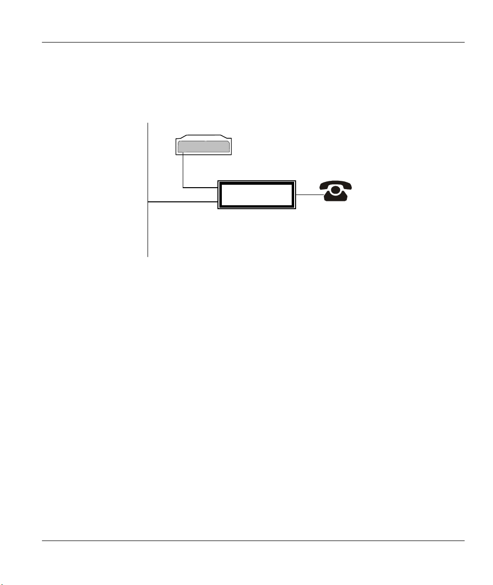
2.4 Connecting a POTS Splitter
This is for the Prestige following the Full Rate (G.dmt) standard only. One major difference between
ADSL and dial-up modems is the optional telephone splitter. This device keeps the telephone and ADSL
signals separated, giving them the capability to provide simultaneous Internet access and telephone service
on the same line. Splitters also eliminate the destructive interference conditions caused by telephone sets.
The purchase of a POTS splitter is optional.
Noise generated from a telephone in the same frequency range as the ADSL signal can be disruptive to the
ADSL signal. In addition the impedance of a telephone when off-hook may be so low that it shunts the
2-2 Hardware Installation & Initial Setup
Prestige 642M Series ADSL Bridge
ode
e
e
strength of the ADSL signal. A POTS splitter will filter the telephone signals before combining the ADSL
and telephone signals transmitted and received. The issues of noise and impedance are eliminated with a
single POTS splitter installation.
A telephone splitter is easy to install as shown in the following figure.
Prestige
M
m
Wall
Jack
POTS Splitter
Lin
Phon
Figure 2-3 Connecting a POTS Splitter
Step 1. Connect the side labeled “Phone” to your telephone.
Step 2. Connect the side labeled “Modem” to your Prestige.
Step 3. Connect the side labeled “Line” to the telephone wall jack.
2.5 Telephone Microfilters
Telephone voice transmissions take place in the lower frequency range, 0 - 4KHz, while ADSL
transmissions take place in the higher bandwidth range, above 4KHz. A microfilter acts as a low-pass filter,
for your telephone, to ensure that ADSL transmissions do not interfere with your telephone voice
transmissions. . The purchase of a telephone microfilter is optional.
Step 1. Connect a phone cable from the wall jack to the single jack end of the Y- Connector.
Step 2. Connect a cable from the double jack end of the Y-Connector to the “wall side” of the
microfilter.
Step 3. Connect another cable from the double jack end of the Y-Connector to the Prestige.
Step 4. Connect the “phone side” of the microfilter to your telephone as shown in the following figure.
Hardware Installation & Initial Setup 2-3
Prestige 642M Series ADSL Bridge
Prestige
Wall
Jack
Y -CONNECTOR
Microfilter
Wall
Side
Phone
Side
Figure 2-4 Connecting a Microfilter
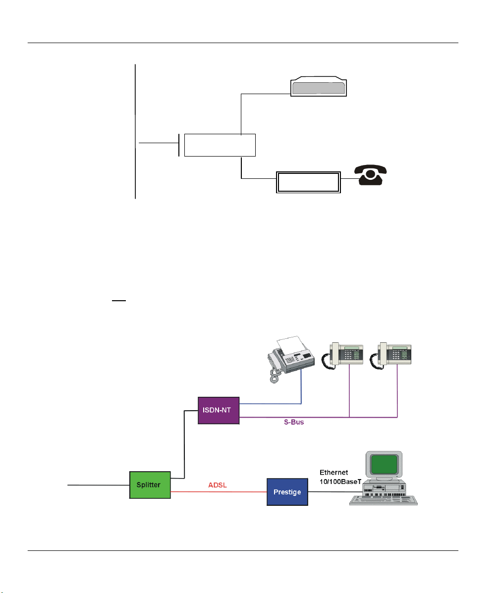
2.6 Special Note for P642M ISDN Users.
Please note that section 2.4 “Connecting a POTS Splitter” and sections 2.5 “Telephone Microfilters” of
this User’s Guide do not apply for P642M ISDN users.
The following is an example installation for the Prestige with ISDN.
Figure 2-5 P642M with ISDN
2-4 Hardware Installation & Initial Setup

Prestige 642M Series ADSL Bridge
2.7 Power Up Your Prestige
At this point, you should have connected the console port, the ADSL line, the Ethernet port and the power
port to the appropriate devices or lines. You can now apply power to the Prestige by turning the switch on.
Step 1.
When you power on your Prestige, it performs several internal tests as well as line initialization. After the
initialization, the Prestige asks you to press [Enter] to continue, as shown below.
Step 2.
The login screen appears after you press [Enter], prompting you to type in your password, as shown below.
For your first login, enter the default password 1234. As you type the password, the screen displays a (X)
for each character you type.
Please note that if there is no activity for longer than 5 minutes after you log in, your Prestige will
automatically log you out and will display a blank screen. If you see a blank screen, press [Enter] to bring
up the login screen again.
Initial Screen
Copyright (c) 1994 - 2000 ZyXEL Communications Corp.
initialize ch =0, ethernet address: 00:a0:c5:01:23:45
HWSAR (FPGA) : programming (11969) ... done
HWSAR (FPGA) : testing ... done
Wan Channel init ........ done
Loading ADSL modem F/W
.……………………………………………………………………………………………………done
Press ENTER to continue...
Figure 2-6 Power-On Display
Entering Password
Enter Password : XXXX
Figure 2-7 Login Screen
Hardware Installation & Initial Setup 2-5
Prestige 642M Series ADSL Bridge
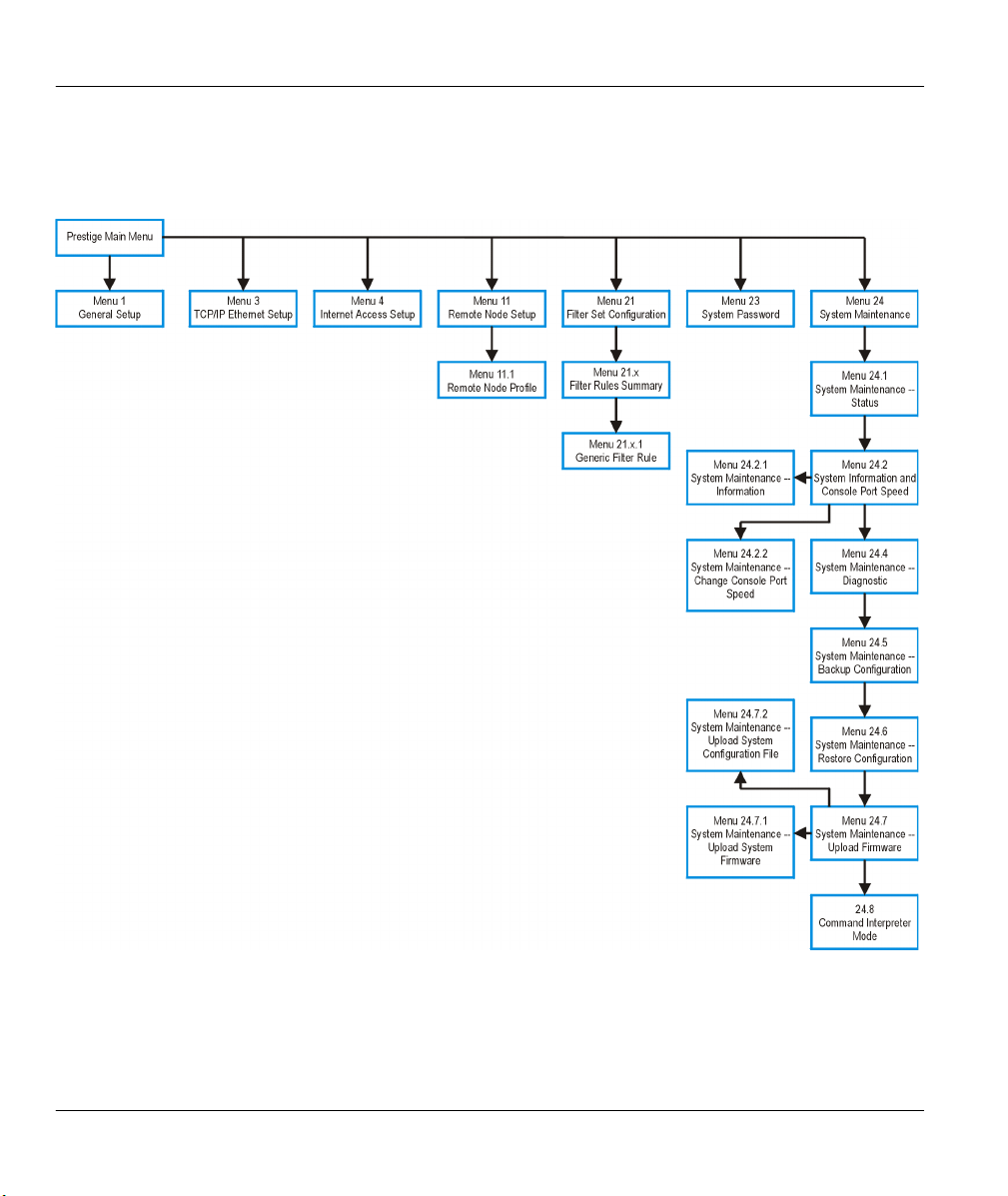
2.7.1 Prestige 642M SMT Menu Overview
The following figure gives you an overview of the various SMT menu screens of your Prestige.
Figure 2-8 Prestige 642M SMT Menu Overview
2-6 Hardware Installation & Initial Setup

Prestige 642M Series ADSL Bridge
2.8 Navigating the SMT Interface
The SMT (System Management Terminal) is the interface that you use to configure your Prestige.
Several operations that you should be familiar with before you attempt to modify the configuration are
listed in the table below.
Table 2-2 Main Menu Commands
Operation Press/Read Description
Move down to
another menu
Move up to a
previous menu
Move to a
“hidden” menu
Move the cursor
Enter information Fill in, or
Required fields
N/A fields <N/A> Some of the fields in the SMT will show a <N/A>. This symbol
Save your
configuration
[Enter] To move forward to a sub-menu, type in the number of the
desired sub-menu and press [Enter].
[Esc] Press the [Esc] key to move back to the previous menu.
Press the [Space
bar] to change No
to Yes then press
[ENTER].
[Enter,] or
[Up]/[Down]
arrow keys
Press the [Space
bar] to toggle
?
<
>
[Enter] Save your configuration by pressing [Enter] at the message
Fields beginning with “Edit” lead to hidden menus and have a
default setting of No. Press the [SPACE BAR] to change No to
Yes, then press [ENTER] to view a “hidden” menu.
Within a menu, press [Enter] to move to the next field. You can
also use the [Up]/[Down] arrow keys to view the previous and
the next field, respectively.
You need to fill in two types of fields. The first requires you to
type in the appropriate information. The second allows you to
cycle through the available choices by pressing the [Space] bar.
All fields with the symbol <?> must be filled in order be able to
save the new configuration.
refers to an option that is Not Applicable.
[Press ENTER to confirm or ESC to cancel]. Saving the data on
the screen will take you, in most cases, to the previous menu.
Exit the SMT
After you enter the password, the SMT displays the Main Menu, as shown below.
Hardware Installation & Initial Setup 2-7
Type 99, then
press [Enter].
Type 99 at the Main Menu prompt and press [Enter] to exit the
SMT interface.

Prestige 642M Series ADSL Bridge
Copyright (c) 1994 - 2000 ZyXEL Communications Corp.
Getting Started
1. General Setup
3. TCP/IP Ethernet Setup
4. Internet Access Setup
Advanced Applications
11. Remote Node Setup
Prestige 642 Main Menu
Advanced Management
21. Filter Set Configuration
23. System Password
24. System Maintenance
99. Exit
Enter Menu Selection Number:
Figure 2-9 SMT Main Menu
2.8.1 System Management Terminal Interface Summary
Table 2-3 Main Menu Summary
# Menu Title Description
1 General Setup Use this information to set up your general information.
3 TCP/IP Ethernet Setup Use this menu to set up your LAN connection.
4 Internet Access Setup A quick and easy way to set up an Internet connection.
11 Remote Node Setup Use this menu to set up the Remote Node for LAN-to-LAN
connection, including Internet connection.
21 Filter Set Configuration Use this menu to set up filters to provide security, etc.
23 System Password Use this menu to change your password.
24 System Maintenance This menu provides system status, diagnostics, software upload, etc.
99 Exit To exit from SMT and return to a blank screen.
2.9 Changing the System Password
The first thing you should do before anything else is to change the default system password by following
the steps below.
Step 1. Enter 23 in the Main Menu to open Menu 23 - System Password as shown below.
Step 2. When the Submenu 23 System Password appears, type in your existing system password, i.e.,
1234, and press [Enter].
2-8 Hardware Installation & Initial Setup

Prestige 642M Series ADSL Bridge
Menu 23 – System Password
Old Password= ****
Retype to confirm= ****
New Password= ****
Enter here to CONFIRM or ESC to CANCEL:
Figure 2-10 Menu 23.1 - System Password
Step 3. Enter your new system password (up to 30 characters) and press [Enter].
Step 4. Re-type your new system password for confirmation and press [Enter].
Note that as you type a password, the screen displays a (*) for each character you
type.
2.10 General Setup
Menu 1 - General Setup contains administrative and system-related information.
To enter Menu 1 and fill in the required information, follow the steps below:
Step 1. Enter 1 in the Main Menu to open Menu 1 – General Setup.
Step 2. The Menu 1 - General Setup screen appears, as shown below. Fill in the required fields marked
[?] and turn on the individual protocols for your applications, as explained in the following table.
Menu 1 - General Setup
System Name= ChangeMe
Location=
Contact Person's Name=
PPPoE Bridge= No
Press ENTER to Confirm or ESC to Cancel:
Press
ENTER to Confirm
or ESC to Cancel:
Figure 2-11 Menu 1 - General Setup
Hardware Installation & Initial Setup 2-9

Prestige 642M Series ADSL Bridge
Table 2-4 General Setup Menu Fields
Field Description Example
System Name Choose a descriptive name for identification purposes. This name
can be up to 30 alphanumeric characters long. Spaces are not
allowed; dashes “-” and underscores "_" are accepted.
Location
(optional)
Contact Person's
Name (optional)
PPPoE Bridge Enable PPPoE by setting PPPoE Bridge= Yes.
Enter the geographic location (up to 31 characters) of your Prestige. MyHouse
Enter the name (up to 30 characters) of the person in charge of this
Prestige.
Note: when PPPoE Bridge= Yes then, in Menu 3, the DHCP=
Server.
Disable PPPoE by setting PPPoE Bridge= No. (this is the default
setting). When PPPoE Bridge= No then, in Menu 3, the default for
DHCP= Server Inact.
P642M
JohnDoe
Yes
No
(default)
2-10 Hardware Installation & Initial Setup

Prestige 642M Series ADSL Bridge
Chapter 3
Internet Access
This chapter shows you how to configure the LAN as well as the WAN
of your Prestige for Internet access
3.1 Factory Ethernet Defaults
The Ethernet parameters of the Prestige are preset in the factory with the following values:
1. IP address of 192.168.1.1 with subnet mask of 255.255.255.0 (24 bits).
These parameters should work for the majority of installations. If you wish to change the factory defaults or
to learn more about TCP/IP then please read on.
3.2 TCP/IP Parameters
3.2.1 IP Address and Subnet Mask
Just as houses on the same street share a common street name so too do computers on the same LAN share
a common network number.
Where you obtain your network number depends on your particular situation. If the ISP or your network
administrator assigns you a block of registered IP addresses, follow their instructions in selecting the IP
addresses and the subnet mask.
The subnet mask specifies the network number portion of an IP address. Your Prestige automatically
computes the subnet mask based on the IP address that you entered. You do not need to change the subnet
mask computed by the Prestige unless you are instructed to do so.
.
3.2.2 Private IP Addresses
Every machine on the Internet must have a unique address. If your networks are isolated from the Internet,
e.g., only between your two branch offices, you can assign any IP addresses to the hosts without problems.
However, the Internet Assigned Numbers Authority (IANA) has reserved the following three blocks of IP
addresses specifically for private networks:
10.0.0.0 - 10.255.255.255
172.16.0.0 - 172.31.255.255
192.168.0.0 - 192.168.255.255
You can obtain your IP address from the IANA, from an ISP or assigned from a private network. If you
belong to a small organization and your Internet access is through an ISP then ISP can provide you with the
Internet addresses for your local networks. On the other hand, if you are part of a much larger organization
then you should consult your network administrator for the appropriate IP addresses.
Note: Regardless of your particular situation, do not create an arbitrary IP address; always follow the
guidelines above. For more information on address assignment, please refer to RFC 1597, Address
Allocation for Private Internets and RFC 1466, Guidelines for Management of IP Address Space.
Internet Access 3-1

Prestige 642M Series ADSL Bridge
p
3.3 TCP/IP Ethernet Setup
You will now use Menu 3 to configure your Prestige for TCP/IP.
To edit Menu 3, enter 3 to open the Menu 3 - TCP/IP Setup from the Main Menu.
Menu 3 – Ethernet TCP/IP & DHCP Setup
DHCP= Server Inact.
Configuration:
Client IP Pool Starting Address= 192.168.1.33
Size of Client IP Pool= 5
Primary DNS Server= 0.0.0.0
Secondary DNS Server= 0.0.0.0
TCP/IP Setup:
IP Address= 192.168.1.1
IP Subnet Mask= 255.255.255.0
Press ENTER to Confirm or ESC to Cancel:
Press S
Follow the instructions in the following table to configure TCP/IP parameters for the Ethernet port.
ace Bar to Toggle.
Figure 3-1 Menu 3 - TCP/IP Ethernet Setup
Table 3-1 TCP/IP Ethernet Setup Menu Fields
Field Description Example
DHCP If the DHCP field is set to
Server
then your Prestige can assign IP
Server
addresses, an IP default gateway and DNS servers to Windows 95,
Windows NT and other systems that support the DHCP client.
Server is the default when, in menu 1, PPPOE=Yes.
If set to None, the DHCP server will be disabled.
Server Inact. inactivates the server. This option is available only
None
Server Inact.
when, in menu 1, the setting for PPPoE Bridge= No. You cannot
toggle this field to Server Inact. directly from Menu 3.
Server Inact. is the default when, in menu 1, PPPoE=No.
When DHCP = Server Inact. then the Client IP Pool Starting
Address, Size of Client IP Pool, Primary DNS Server and
Secondary DNS Server have N/A fields.
Configuration:
When DHCP is used, that is DHCP= Server, the following items
need to be set:
Client IP Pool
Starting
This field specifies the first of the contiguous addresses in the IP
address pool.
192.168.1.33
Address
3-2 Internet Access

Prestige 642M Series ADSL Bridge
Size of Client
IP Pool
Primary DNS
Secondary
DNS Server
TCP/IP Setup
IP Address Enter the (LAN) IP address of your Prestige in dotted decimal
IP Subnet Mask Your Prestige will automatically calculate the subnet mask based on
When you have completed this menu, press [Enter] at the prompt [Press ENTER to Confirm…] to
save your configuration, or press [Esc] at any time to cancel.
This field specifies the size or count of the IP address pool.
Enter the IP addresses of the DNS servers. The DNS servers are
Server
passed to the DHCP clients along with the IP address and the subnet
mask.
notation.
the IP address that you assign. Unless you are implementing
subnetting, use the subnet mask computed by the Prestige.
5
0.0.0.0
0.0.0.0
192.168.1.1
(default)
255.255.255.0
3.4 LANs & WANs
A LAN (Local Area Network) is a computer network limited to the immediate area, usually the same
building or floor of a building. A WAN (Wide Area Network), on the other hand is an outside connection to
another network or the Internet.
3.4.1 LANs, WANs and the Prestige
The actual physical connection determines whether the Prestige ports are LAN or WAN ports. There are
two separate IP networks, one inside, the LAN network; the other outside, the WAN network as shown
next.
Figure 3-2 LAN & WAN
Internet Access 3-3

Prestige 642M Series ADSL Bridge
3.5 VPI & VCI
Be sure to use the correct Virtual Path Identifier (VPI) and Virtual Channel Identifier (VCI) numbers
supplied by the telephone company. The valid range for the VPI is 1 to 255 and for the VCI is 32 to 65535
(0 to 31 is reserved for local management of ATM traffic). Please see the VPI & VCI Appendix for more
information.
3.6 Multiplexing
There are two conventions to identify what protocols the virtual circuit (VC) is carrying. Be sure to use the
multiplexing method required by your ISP.
3.6.1 VC-based multiplexing
In this case, by prior mutual agreement, each protocol is assigned to a specific virtual circuit, e.g., VC1
carries IP, VC2 carries IPX, etc. VC-based multiplexing may be dominant in environments where dynamic
creation of large numbers of ATM VCs is fast and economical.
3.6.2 LLC-based multiplexing
In this case one VC carries multiple protocols with protocol identifying information being contained in each
packet header. Despite the extra bandwidth and processing overhead, this method may be advantageous if it
is not practical to have a separate VC for each carried protocol, e.g., if charging heavily depends on the
number of simultaneous VCs.
3.7 Encapsulation
Be sure to use the encapsulation method required by your ISP. The Prestige supports the following
methods.
3.7.1 PPP
Please refer to RFC 2364 for more information on PPP over ATM Adaptation Layer 5 (AAL5). Refer to
RFC 1661 for more information on PPP.
3.7.2 RFC 1483
RFC 1483 describes two methods for Multiprotocol Encapsulation over ATM Adaptation Layer 5 (AAL5).
The first method allows multiplexing of multiple protocols over a single ATM virtual circuit (LLC-based
multiplexing) and the second method assumes that each protocol is carried over a separate ATM virtual
circuit (VC-based multiplexing). Please refer to the RFC for more detailed information.
3.8 Internet Access Configuration
Menu 4 allows you to enter the Internet Access information in one screen. Menu 4 is actually a simplified
setup for one of the remote nodes that you can access in Menu 11. Before you configure your Prestige for
Internet access, you need to collect your Internet account information from your ISP and telephone
company.
Use the following table to record your Internet Account Information. Note that if you are using PPP then
the only ISP information you need is a login name and password.
3-4 Internet Access

Prestige 642M Series ADSL Bridge
Table 3-2 Internet Account Information
Internet Account Information Write your account information here
Telephone Company Information
VPI (Virtual Path Identifier)
−
VCI (Virtual Channel Identifier)
Login Name
Password for ISP authentication
Type of Multiplexing
Type of Encapsulation
From the Main Menu, enter 4 to go to Menu 4 - Internet Access Setup, as displayed below. The following
table contains instructions on how to configure your Prestige for Internet access.
Menu 4 - Internet Access Setup
ISP's Name= ChangeMe
Encapsulation= RFC 1483
Multiplexing= LLC-based
Get this information from
the telephone company. Get
the other information from
your ISP.
VPI #= 8
VCI #= 35
My Login= N/A
My Password= N/A
Press ENTER to confirm or ESC to cancel:
Press ENTER to Confirm or ESC to Cancel:
−
ISP Information
−
−
−
−
Figure 3-3 Internet Access Setup
Internet Access 3-5

Prestige 642M Series ADSL Bridge
Table 3-3 Internet Access Setup Menu Fields
Field
Enter the name of your Internet Service Provider, e.g.,
ISP’s Name
myISP. This information is for identification purposes
only.
Press the [spacebar] to select the method of encapsulation
Encapsulation
used by your ISP. Please see section 3.7 for related
information.
Press the [Space Bar] to select the method of multiplexing
Multiplexing
used by your ISP - either VC-based or LLC-based.
Description Options/E.G.
e.g., MyISP
PPP
RFC 1483
VC-based
LLC-based
VPI #
VCI #
My Login
My Password
Enter the Virtual Path Identifier (VPI) that the telephone
company gives you.
Enter the Virtual Channel Identifier (VCI) that the
telephone company gives you.
Enter the login name that your ISP gives you.
Enter the password associated with the login name above.
e.g., 0
e.g., 33
e.g., tarbuck
*******
3-6 Internet Access

Prestige 642M Series ADSL Bridge
Chapter 4
Remote Node Configuration
This chapter shows you how to configure a remote node.
A remote node is required for placing calls to a remote gateway. A remote node represents both the remote
gateway and the network behind it across a WAN connection. Note that when you use Menu 4 to set up
Internet access, you are actually configuring one of the remote nodes.
4.1 Remote Node Setup
This section describes the protocol-independent parameters for a remote node.
4.1.1 Remote Node Profile
To configure a remote node, follow these steps:
Step 1. From the Main Menu, select Menu 11 – Remote Node Setup.
Step 2. When Menu 11 appears, as shown below, enter the number of the remote node that you wish to
configure.
Menu 11 - Remote Node Setup
1. ChangeMe (ISP)
2. ________
3. ________
4. ________
5. ________
6. ________
7. ________
8. ________
Enter Node # to Edit:
Figure 4-1 Menu 11- Remote Node Setup
When Menu 11.1 - Remote Node Profile appears fill in the fields as described in the table that follows to
define this remote profile. The Remote Node Profile Menu Fields table shows you how to configure the
Remote Node Menu.
4.1.2 Encapsulation & Multiplexing Scenarios
For Internet Access you should use the encapsulation and multiplexing methods used by your ISP. For a
LAN-to-LAN application, e.g., branch office and corporate headquarters, prior mutual agreement on
methods used is necessary because there is no mechanism to automatically determine
encapsulation/multiplexing. Selection of which encapsulation and multiplexing methods to use depends on
Remote Node Configuration 4-1

Prestige 642M Series ADSL Bridge
how many VCs you have and how many different network protocols you need. Here are some examples of
combinations.
Scenario 1. One VC, Multiple Protocols
PPP (RFC 2364) encapsulation with VC-based multiplexing is the best combination because the extra
protocol identifying headers that LLC-based multiplexing uses is unneeded. The PPP protocol already
contains this information.
Scenario 2. One VC, One Protocol (IP)
Select RFC-1483 encapsulation with VC-based multiplexing requires the least amount of overhead (0
octets). However, if there is a potential need for multiple protocol support in the future, it may be safer to
select PPP encapsulation instead of RFC-1483, so you don’t need to reconfigure either machine when the
time comes.
Scenario 3. Multiple VCs
If you have an equal number (or more) of VCs than the number of protocols, then select RFC-1483
encapsulation and VC-based multiplexing.
Menu 11.1 - Remote Node Profile
Node Name= ChangeMe
Active= Yes
Encapsulation= RFC 1483
Multiplexing= LLC-based
Incoming:
Rem Login= N/A
Rem Password= N/A
Outgoing:
My Login= N/A
My Password= N/A
Authen= N/A
Press ENTER to Confirm or ESC to Cancel:
Bridge:
Ethernet Addr Timeout(min)= 0
VPI #= 8
VCI #= 35
Filter Sets:
Input Device Filters=
Output Device Filters=
Enter a
unique name
of less than 8
characters for
the remote
name.
Figure 4-2 Menu 11.1 - Remote Node Profile
4-2 Remote Node Configuration

Prestige 642M Series ADSL Bridge
Table 4-1 Remote Node Profile Menu Fields
Field Description Options
Rem Node Name
Active
Encapsulation=
Multiplexing= Press the spacebar to the select the multiplexing method.
Incoming:
Rem Login Name Enter the login name that this remote node will use when it
Rem Password Enter the password used when this remote node calls your
Outgoing:
My Login
My Password
Authen
This is a required field ([?]). Enter a descriptive name for the
remote node, for example, Corp. This field can be up to eight
characters. This name must be unique from any other remote
node name.
Press the spacebar to toggle between Yes and No. Inactive
nodes are displayed with a minus sign (-) at the beginning of
the name in Menu 11.
PPP refers to RFC 2364, "PPP Encapsulation over ATM
Adaptation Layer 5". If RFC 1483 ("Multiprotocol
Encapsulation over ATM Adaptation Layer 5") is selected,
then the Rem Login, Rem Password, My Login, My
Password, Edit PPP Options and Authen fields will not be
applicable (N/A).
calls your Prestige.
The login name in this field combined with the Rem Node
Password will be used to authenticate this node.
Prestige.
Enter the login name for your Prestige when it calls this
remote node.
Enter the password for your Prestige when it calls this
remote node.
This field sets the authentication protocol used for outgoing
calls.
z CHAP/PAP - Your Prestige will accept either CHAP
or PAP when requested by this remote node.
z CHAP - accept CHAP only.
z PAP - accept PAP only.
Yes/No
PPP,
RFC 1483
VC-based
LLC-based
CHAP/PAP
CHAP
PAP
Remote Node Configuration 4-3

Prestige 642M Series ADSL Bridge
Field Description Options
Bridge
Ethernet Addr
Timeout (min)
VPI#
VCI#
Filter Sets:
Input Device Filters= Specify the incoming filter sets here.
Output Device Filters= Specify the outgoing filter sets here.
Once you have completed filling in Menu 11.1 – Remote Node Profile, press [Enter] at the message
[Press ENTER to Confirm…] to save your configuration or press [Esc] at any time to cancel.
In this field, enter the time (number of minutes) that you
wish your Prestige 642 to retain the Ethernet Addr
information in its internal tables while the line is down. If
this information is retained, your Prestige 642 will not have
to recompile the tables when the line is brought back up.
Select a different PVC by changing the VPI, VCI numbers.
Enter the Virtual Path Identifier (VPI) number for this PVC.
Enter the Virtual Channel Identifier (VCI) number for this
PVC.
Specify the filter set(s) to apply to the incoming and
outgoing traffic between this remote node and the Prestige.
You can specify up to 4 filter sets separated by comma, e.g.,
1, 5, 9, 12, in each filter field. The default is no filters. Note
that spaces are accepted in this field. For more information
on defining the filters, see the chapter on Filter
Configuration.
4-4 Remote Node Configuration

Prestige 642M Series ADSL Bridge
Chapter 5
Filter Configuration
This chapter shows you how to create and apply filter(s).
5.1 About Filtering
Your Prestige uses filters to decide whether or not to allow passage of a packet. Data filters are divided
into incoming and outgoing filters, depending on the direction of the packet relative to a port. These filters
are further subdivided into device and protocol filters, which are discussed later. The Prestige 642M
ADSL Bridge has device filters only. Device filters are applied to raw packets that appear on the wire.
They are applied at the point when the Prestige is receives and sends packets; i.e. the interface. The
interface can be an Ethernet, or any other hardware port.
The following sections describe how to configure filter sets.
The Filter Structure of the Prestige
A filter set consists of one or more filter rules. Usually, you would group related rules. The Prestige allows
you to configure up to twelve filter sets with six rules in each set, for a total of 72 filter rules in the system.
The following diagram illustrates the logic flow when executing a filter rule.
Filter Configuration 5-1

Prestige 642M Series ADSL Bridge
Filter Set
Start
Packet into
filter
Fetch First
Filter Set
Fetch Next
Filter Set
Yes
Next Filter Set
Available?
No
Fetch Next
Filter Rule
Yes
Next filter
Rule
Available?
No
Fetch First
Filter Rule
Active?
Yes
Execute
No
Check
Next
Rule
Figure 5-1 Filter Rule Process
You can apply up to four filter sets to a particular port to block multiple types of packets. With each filter
set having up to six rules, you can have a maximum of 24 rules active for a single port.
Filter Rule
Forward
Drop
Accept PacketDrop Packet
5-2 Filter Configuration

Prestige 642M Series ADSL Bridge
5.2 Configuring a Filter Set
To configure filter sets or a filter set, follow the procedure below.
Step 1. Enter 21 from the Main Menu to open Menu 21 - Filter Set Configuration.
Menu 21 - Filter Set Configuration
Filter
Set #
----- 1
2
3
4
5
6
Comments
-----------------test
______________
______________
______________
Enter Filter Set Number to Configure= 0
Edit Comments= N/A
Press ENTER to Confirm or ESC to Cancel:
Figure 5-2 Menu 21 - Filter Set Configuration
Step 2. Enter the index of the filter set you wish to configure (no. 1-12) and press [Enter].
Step 3. Enter a descriptive name or comment in the Edit Comments field and press [Enter].
Step 4. Press [Enter] at the message “Press ENTER to Confirm or ESC to Cancel” to open Menu 21.1
- Filter Rules Summary.
Filter
Set #
-----7
8
9
10
11
12
Comments
-----------------______________
______________
______________
______________
______________
______________
Filter Configuration 5-3

Prestige 642M Series ADSL Bridge
Menu 21.1 - Filter Rules Summary
# A Type Filter Rules M m n
- - ---- ----------------------------------------------------------------- - - -
1 Y Off=128, Len=4, Mask=789abcde, Value=789abcde N D F
2 N
3 N
4 N
5 N
6 N
21
Enter Filter Rule Number (1-6) to Configure:
Figure 5-3 Filter Rules Summary
5.2.1 Filter Rules Summary Menu
This screen shows a summary of the existing rules in an example filter set. The following tables contain a
brief description of the abbreviations used in Menu 21.1.
Table 5-1 Abbreviations Used in the Filter Rules Summary Menu
Abbreviations Description Display
# Refers to the filter rule number (1-6).
A Refers to Active. [Y] means the filter rule is active.
[N] means the filter rule is inactive.
Type Refers to the type of filter rule.
This shows GEN for generic, meaning
device filter rule.
Filter Rules
The filter rule parameters are displayed
here (see below).
M Refers to More.
[Y] means an action can not yet be taken
as there are more rules to check, which
are concatenated with the present rule to
form a rule chain. When the rule chain is
complete an action can be taken.
[GEN] for Generic.
[Y]
[N]
5-4 Filter Configuration

Prestige 642M Series ADSL Bridge
Abbreviations Description Display
[N] means you can now specify an
action to be taken i.e., forward the
packet, drop the packet or check the next
rule. For the latter, the next rule is
independent of the rule just checked.
If More is Yes, then Action Matched
and Action Not Matched will be N/A.
m Refers to Action Matched.
[F] means to forward the packet
immediately and skip checking the
remaining rules.
n Refers to Action Not Matched.
[F] means to forward the packet
immediately and skip checking the
remaining rules.
The protocol dependent filter rules abbreviations are listed as follows:
z If the filter type is GEN (generic, i.e., device), then the abbreviations listed in the following table are
used.
[F] means to forward the packet.
[D] means to drop the packet.
[N] means check the next rule.
[F] means to forward the packet.
[D] means to drop the packet.
[N] means check the next rule.
Table 5-2 Abbreviations Used if Filter Type Is GEN
Abbreviation Description
Off Offset
Len Length
Refer to the next section for information on configuring filter rules.
5.3 Configuring a Filter Rule
To configure a filter rule, enter its number in Menu 21.1 - Filter Rules Summary and press [Enter].
There is one type of filter rule, Device for the P642M ADSL Bridge.
5.3.1 Generic Filter Rule
This section shows you how to configure a generic filter rule.
For generic rules, the Prestige treats a packet as a byte stream. You specify the portion of the packet to
check with the Offset (from 0) and the Length fields, both in bytes. The Prestige applies the Mask (bitwise ANDing) to the data portion before comparing the result against the Value to determine a match. The
Mask and Value are specified in hexadecimal numbers. Note that it takes two hexadecimal digits to
Filter Configuration 5-5

Prestige 642M Series ADSL Bridge
represent a byte. If the length is four, for example, then the value in either field will take 8 digits (e.g.,
FFFFFFFF).
To configure a generic rule, select Generic Filter Rule in the Filter Type field and press [Enter] to open
Menu 21.1.2 - Device Filter Rule, as shown next.
Menu 21.1.2 - Generic Filter Rule
Filter #: 1,2
Active= No
Offset= 0
Length= 0
Mask= N/A
Value= N/A
More= No Log= None
Action Matched= Check Next Rule
Action Not Matched= Check Next Rule
Press ENTER to Confirm or ESC to Cancel:
Press Space Bar to Toggle.
Figure 5-4 Menu 21.1.2 - Generic Filter Rule
The following table describes the fields in the Generic Filter Rule Menu.
Table 5-3 Generic Filter Rule Menu Fields
Field Description Option
Filter #
This is the filter set, filter rule co-ordinates, i.e., 2,3 refers to the second
filter set and the third filter rule of that set.
Active Select Yes to turn on the filter rule.
Offset Enter the starting byte of the data portion in the packet that you wish to
Yes/No
Default = 0
compare. The range for this field is from 0 to 255.
Length Enter the byte count of the data portion in the packet that you wish to
Default = 0
compare. The range for this field is 0 to 8.
Mask Enter the mask (in Hexadecimal) to apply to the data portion before
comparison.
Value Enter the value (in Hexadecimal) to compare with the data portion.
More
If yes, a matching packet is passed to the next filter rule before an action is
Yes / N/A
taken; else the packet is disposed of according to the action fields.
If More is Yes, then Action Matched and Action Not Matched will be
N/A.
5-6 Filter Configuration

Prestige 642M Series ADSL Bridge
Field Description Option
Log Select the logging option from the following:
z None – No packets will be logged.
z Action Matched - Only packets that match the rule parameters will
be logged.
z Action Not Matched - Only packets that do not match the rule
parameters will be logged.
z Both – All packets will be logged.
Action
Matched
Action
Not
Matched
Once you have completed filling in Menu 21.1.2 - Generic Filter Rule, press [Enter] at the message
[Press Enter to Confirm] to save your configuration or press [Esc] to cancel. This data will now be
displayed on Menu 21.1 - Filter Rules Summary.
Select the action for a matching packet.
Select the action for a packet not matching the rule.
None
Action
Matched
Action Not
Matched
Both
Check Next
Rule
Forward
Drop
Check Next
Rule
Forward
Drop
5.4 Example Filter
Let’s look at an example filter. Please see our supporting disk for more example filters.
Step 1. Enter 21 from the Main Menu to open Menu 21 - Filter Set Configuration.
Step 2. Enter the index of the filter set you wish to configure (in this case, 1) and press [ENTER]
Step 3. Enter a descriptive name or comment in the Edit Comments field (in this case test) and press
[ENTER].
Step 4. Press [ENTER] at the message: [Press ENTER to confirm] and to open Menu 21.1 - Filter
Rules Summary.
Step 5. Enter 1 to configure the first filter rule (the only filter rule of this set). Make the entries in this
menu as shown in the following figure.
Filter Configuration 5-7
.

Prestige 642M Series ADSL Bridge
This is the length (in bytes) of the data portion in the packet that you want to compare.
The Mask is applied to the data portion before comparing the result against the Value to determine a match.
It is specified in hexadecimal, and it takes two hexadecimal digits to represent a byte i.e., Length is 4,
therefore there are 8 hex numbers.
Filter #: 1,1
Active= Yes
Offset= 128
Length= 4
Mask= 789abcde
Value= 789abcde
More= No Log= Action Matched
Action Matched= Forward
Action Not Matched= Drop
Press Space Bar to Toggle.
Menu 21.1.1 - Generic Filter Rule
Press ENTER to Confirm or ESC to Cancel:
There are no more rules
to check in this filter set.
Select Drop here
Select Forward here so
that the packet will be
forwarded if the action is
matched.
so that the packet
will be dropped
if the action is
not matched.
Select Yes to make the rule
active.
This is the first byte of the
data portion in the packet that
you.
This is the length (in bytes) of
the data portion in the packet
that you want to compare.
The Mask is applied to the
data portion before comparing
the result against the Value to
determine a match. It is
specified in hexadecimal, and
it takes two hexadecimal
digits to represent a byte i.e.,
Length is 4, therefore there
are 8 hex numbers.
Enter the value (in hex) to
compare with the data
portion.
This setting logs all packets
that match these rule
parameters.
Figure 5-5 Example Filter - Menu 21.1.1
Press [ENTER] to confirm and you will see the following screen. Note that there is only one filter rule in
this set.
5-8 Filter Configuration

Prestige 642M Series ADSL Bridge
Menu 21.1 - Filter Rules Summary
# A Type Filter Rules M m n
- - ---- --------------------------------------------------------------- - - 1 Y Gen Off=128, Len=4, Mask=789abcde, Value=789abcde N D F
2 N
3 N
4 N
5 N
6 N
Enter Filter Rule Number (1-6) to Configure: 1
This shows you what you
configured in the previous
menu.
M = N means an action can be taken
immediately. The action is to drop the
packet (m = D) if the action is matched and
to forward the packet immediately (n = F) if
the action is not matched no matter whether
there are more rules to be checked (there
aren’t in this example).
Figure 5-6 Example Filter Rules Summary - Menu 21.1
After you create the filter set you must apply it.
5.5 Applying a Filter
This section shows you where to apply the filter(s) after you design it (them).
5.5.1 Remote Node Filters
Go to Menu 11.1 (shown next) and enter the number(s) of the filter set(s) as appropriate. You can cascade
up to four filter sets by entering their numbers separated by commas.
Filter Configuration 5-9

Prestige 642M Series ADSL Bridge
Menu 11.1 - Remote Node Profile
Rem Node Name= nodename
Active= Yes
Encapsulation= RFC 1483
Multiplexing= LLC-based
Incoming:
Rem Login= N/A
Rem Password= N/A
Outgoing:
My Login= N/A
My Password= N/A
Authen= N/A
Enter here to CONFIRM or ESC to CANCEL:
Figure 5-7 Filtering Remote Node Traffic
Bridge:
Ethernet Addr Timeout(min)= 0
VPI #= 8
VCI #= 35
Filter Sets:
Input Device Filters=
Output Device Filters=
Apply a filter
by entering
the filter set
number here.
5-10 Filter Configuration

Prestige 642M Series ADSL Bridge
Chapter 6
System Maintenance
This chapter covers the diagnostic tools that help you to maintain your Prestige.
The diagnostic tools include updates on system status, port status, log and trace capabilities and upgrades
for the system software. This chapter describes how to use these tools in detail.
[Enter} 24 in the main menu to open Menu 24 - System Maintenance, as shown below.
Menu 24 - System Maintenance
1. System Status
2. System Information and Console Port Speed
4. Diagnostic
5. Backup Configuration
6. Restore Configuration
7. Upload Firmware
8. Command Interpreter Mode
Enter Menu Selection Number:
Figure 6-1 Menu 24 - System Maintenance
6.1 System Status
The first selection, System Status, gives you information on the status and statistics of the ports, as shown
below. System Status is a tool that can be used to monitor your Prestige. Specifically, it gives you
information on your ADSL line status, number of packets sent and received.
To get to the System Status, enter number 24 view Menu 24 - System Maintenance. From this menu,
select number 1, System Status. There are two commands in Menu 24.1 - System Maintenance - Status.
Entering 1 resets the counters and ESC takes you back to the previous screen.
The table below describes the fields present in Menu 24.1 - System Maintenance - Status. It should be
noted that these fields are READ-ONLY and are for diagnostic purposes.
Please note that displaying this screen degrades system performance.
System Maintenance 6-1

Prestige 642M Series ADSL Bridge
Menu 24.1 -- System Maintenance – Status
Node-Lnk
1-1483
2
3
4
5
6
7
8
Status
Up
N/A
N/A
N/A
N/A
N/A
N/A
N/A
TxPkts
211
0
0
0
0
0
0
0
RxPkts
Errors
0
0
0
0
0
0
0
0
Tx B/s
0
0
0
0
0
0
0
0
222
Rx B/s
0
0
0
0
0
0
0
Up Time
2:15:16
0
0:00:00
0
0:00:00
0
0:00:00
0
0:00:00
0
0:00:00
0
0:00:00
0
0:00:00
0
Ethernet:
Status: 10M/Full Duplex
Collisions: 0
CPU Load = 4.25%
Tx Pkts: 1583
Rx Pkts: 1521
COMMANDS: 1-Reset Counters ESC-Exit
Press Command:
WAN:
Line Status: Up
Upstream Speed: 608 kbps
Downstream Speed: 4000 kbps
Figure 6-2 Menu 24.1 - System Maintenance - Status
The following table describes the fields present in Menu 24.1 - System Maintenance - Status.
6-2 System Maintenance

Prestige 642M Series ADSL Bridge
Table 6-1 System Maintenance - Status Menu Fields
Field Description
This is the remote node index number and link type. Link types are :Node-Lnk
PPP and 1483
Status Shows the status of the remote node.
TxPkts The number of packets transmitted to this remote node.
RxPkts The number of packets received from this remote node.
Errors The number of error packets on this connection.
Tx B/s Shows the transmission rate in bytes per second.
Rx B/s Shows the receiving rate in bytes per second.
Up Time Time this channel has been connected to the remote node.
Ethernet
Status Shows the current status of the LAN.
Tx Pkts The number of transmitted packets to the LAN.
Rx Pkts The number of received packets from the LAN.
Collision Number of collisions.
WAN
Line Status
Upstream Speed Shows the ADSL line upstream speed.
Downstream Speed Shows the ADSL line downstream speed.
CPU Load Specifies the percentage of CPU utilization.
Press Command
1 - Reset Counters Press 1 to reset all the above statistics to 0.
ESC - Exit Press ESC to go back to Menu 24.
Shows the current status of the ADSL line which can be Up, Down,
Wait for Init or Initializing.
6.2 System Information and Console Port Speed
Select option 2 to reach Menu 24.2 System Information and Console Port Speed as shown below:
System Maintenance 6-3

Prestige 642M Series ADSL Bridge
Menu 24.2 - System Information and Console Port Speed
1. System Information
2. Console Port Speed
Please enter selection:
Figure 6-3 System Information and Console Port Speed
6.2.1 System Information
Press 1 to display the next screen, Menu 24.2.1 - System Maintenance - Information. This menu details
current information as it relates to your Prestige.
Menu 24.2.1 – System Maintenance - Information
Name: ChangeMe
Routing:BRIDGE
ZyNOS S/W Version: V2.50(AR.0) | 11/16/2000
ADSL Chipset Vendor: Alcatel, Version 3.6.70
Standard: Multi-Mode
LAN
Press ESC or RETURN to Exit:
Figure 6-4 System Maintenance - Information
Ethernet Address:00:a0:c5:01:23:45
IP Address: 192.168.1.1
IP Mask: 255.255.255.0
DHCP: Server Inact.
Table 6-2 Fields in System Maintenance - Information
Field Description
Name Displays the system name of your Prestige. This information can be
modified in Menu 1 - General Setup.
ZyNOS S/W
Version
ADSL Chipset
Vendor
Refers to the ZyNOS (ZyXEL Network Operating System) software
version and date created. Note that M refers to Modem. ZyNOS is a
registered trademark of ZyXEL Communications Corporation.
Displays the vendor of the ADSL chipset and ADSL bridge
software version.
Standard: Displays the Standard.
Ethernet Address Refers to the Ethernet MAC (Media Access Control) of your
Prestige.
IP Address This is the IP address of the Prestige in dotted decimal notation.
IP Mask This shows the subnet mask of the Prestige.
DHCP This default field is Server Inact. for this model.
6-4 System Maintenance

Prestige 642M Series ADSL Bridge
6.2.2 Console Port Speed
You can change the speed of the console port through Menu 24.2.2 - Console Port Speed. Your Prestige
supports 9600 (default), 19200, 38400, 57600, and 115200 bps for the console port. Use the space bar to
select the desired speed in Menu 24.2.2, as shown in the following figure.
Menu 24.2.2 – System Maintenance – Change Console Port Speed
Console Port Speed: 9600
Press ENTER to Confirm or ESC to Cancel:
Press Space Bar to Toggle.
Figure 6-5 Menu 24.2.2 - System Maintenance - Console Port Speed
6.3 Diagnostic
The diagnostic facility allows you to test the different aspects of your Prestige to determine if it is working
properly. Menu 24.4 allows you to choose among various types of diagnostic tests to evaluate your system,
as shown.
Menu 24.4 - System Maintenance - Diagnostic
ADSL
1. Reset ADSL
TCP/IP
12. Ping Host
System
21. Reboot System
22. Command Mode
Enter Menu Selection Number:
Host IP Address= N/A
Figure 6-6 Menu 24.4 - System Maintenance - Diagnostic
Follow the procedure below to get to Diagnostic.
Step 1. From the Main Menu, enter 24 to open Menu 24 - System Maintenance.
Step 2. From this menu, enter 4 to open Menu 24.4 - System Maintenance - Diagnostic.
The following table describes the diagnostic tests available in Menu 24.4 for your Prestige and the
connections.
System Maintenance 6-5

Prestige 642M Series ADSL Bridge
Table 6-3 System Maintenance Menu Diagnostic
Field
Reset ADSL This command re-initializes the ADSL link to the telephone company.
Ping Host This diagnostic test pings the host, which determines the functionality of the
Reboot System This option reboots the Prestige.
Command Mode
Description
TCP/IP protocol on both systems and the links in between.
This option allows you to enter the command mode. This mode allows you
to diagnose and test your Prestige using a specified set of commands.
6.4 A Note about Filenames
The configuration file (often called the romfile or romfile-0) contains the factory default settings in the
menus such as password, DHCP Setup, TCP/IP Setup etc. It arrives from ZyXEL with a name of
P642M.rom or something similar. Once you have customized the Prestige's setting, they can be saved back
to your computer under a filename of your choosing. Choose something meaningful, e.g. “MyP642M.cfg”.
The ZyNOS firmware file (sometimes referred to as the ras file) is the file that contains the ZyXEL
Network Operating System firmware and usually is the router model name with a *.bin extension, e.g.,
P642M.bin.
With serial (Xmodem) transfer and many ftp and tftp clients (see next), the filenames on the PC are your
choice.
ftp> put P642M.bin ras
This is a sample ftp session showing the transfer of the your computer "P642M.bin" to the Prestige.
ftp> get rom-0 MyP642M.cfg
This is a sample ftp session saving the current configuration to the file MyP642M.cfg on your computer.
If your [t]ftp client does not allow you to have a destination filename different from the source, you will
need to rename them, as the Prestige only recognizes "rom-0" and "ras". Be sure you keep unaltered copies
of both files for later use.
The following table is a summary. Please note that the internal filename refers to the filename on the
Prestige and the external filename refers to the filename not on the Prestige, i.e., on your workstation, local
network or ftp site and so the name (but not the extension) will vary. The AT command is the command
you enter after you press “Y” when prompted in the SMT menu to go into debug mode.
6-6 System Maintenance

Prestige 642M Series ADSL Bridge
Internal Filename Description External
Filename
ras This is the firmware filename for
*.bin put P642M.bin ras
all Prestige models.
rom-0 The rom-0 configuration file is
*.rom put P642M.rom rom-0
the entire factory configuration
file. It includes rom-0, default
settings, file system, log, etc.
Uploading the rom-0 file replaces
the entire ROM file system,
including your Prestige
configurations, system-related
data (including the baud rate and
default password), the error log
and the trace log.
Table 6-4 Filenames
Connected to 202.a.b.c
220 P642M FTP version 1.0 ready at Thu Jan 8 18:00:02 1970
User (202.a.b.c:(none)):
331 Enter PASS command
Password:
230 Logged in
ftp> dir
200 Port command okay
150 Opening data connection for LIST
--w--w--w- 1 owner group 885146 Jul 01 12:00 ras
--w--w--w- 1 owner group 327680 Jul 01 12:00 rom-0
226 File sent OK
ftp: 325 bytes received in 0.00Seconds 325000.00Kbytes/sec.
ftp> put p642M.rom rom-0
200 Port command okay
150 Opening data connection for STOR rom-0
226 File received OK
ftp: 327680 bytes sent in 1.10Seconds 297.89Kbytes/sec.
ftp quit
FTP Command
Example
External
Filename.
Internal
Filename.
Figure 6-7 External and Internal Filenames
Note: Always refer to the ZyNOS F/W Version field in Menu 24.2.1 to verify your
current firmware version.
System Maintenance 6-7

Prestige 642M Series ADSL Bridge
6.4.1 Firmware Development
It is important to upgrade your firmware regularly, especially if there are problems. If you discover an
unexpected behavior, or bug, see if your problem is mentioned in the release notes. Load it according to
instructions (e.g., see if the default configuration file is needed also). If the problem still exists, e-mail or
call tech support.
6.5 Backup Configuration
6.5.1 Backup using the Console Port
Option 5 from Menu 24 – System Maintenance allows you to save the current Prestige configuration file
to your workstation. Backup is highly recommended once your Prestige is functioning properly.
You can perform the backup either through an FTP or TFTP client program (preferred method) or through
the RS-232 console port (in the event of the network being down). Backup via the console port under
normal conditions
should work fine; however, you must use the XMODEM protocol to perform the download/upload.
Step 1. Go to menu 24.5.
Ready to backup Configuration via Xmodem.
Do you want to continue (y/n):
Step 2. Press “Y” to indicate that you want to continue. The following procedure is for the
Step 3. Click “Transfer” in the HyperTerminal menu bar, then “Receive File” from the drop-down menu
is not recommended since FTP or TFTP is faster. Any serial communications program
Figure 6-8 Menu 24.5 - Menu 24.5 as seen using the Console Port
HyperTerminal program. The procedure for other serial communications programs should be
similar.
to display the following screen. Follow the instructions as shown.
Enter where you want to
place the rom configuration
file on your computer.
Finally, click
Receive.
Choose the
Xmodem
Protocol.
Figure 6-9 Backup Example Using HyperTerminal
Step 4. After a successful backup you will see the following screen. Press any key to return to the SMT
menu.
6-8 System Maintenance

Prestige 642M Series ADSL Bridge
** Backup Configuration completed. OK.
### Hit any key to continue.###
Figure 6-10 Successful Backup Confirmation Screen
6.5.2 Backup using FTP
To transfer the configuration file, follow the instructions as shown in the following screen. For details on
FTP commands, please consult the documentation of your FTP client program.
To transfer the configuration file to your workstation, follow the procedure
below:
1. Launch the FTP client on your workstation.
1. Type “open” and the IP address of your system. Then type “root” and
SMT password as requested.
3. Locate the “rom-0” file.
3. Type “get rom-0” to back up the current system configuration to your
workstation.
For details on FTP commands, please consult the documentation of your FTP
client program. For details on backup using TFTP (note that you must remain
in this menu to back up using TFTP), please see your user manual.
Press ENTER to Exit:
Menu 24.5 – Backup Configuration
Figure 6-11 FTP Session Example as seen Using Telnet
6.5.3 Backup using TFTP
Even though TFTP should work over WAN as well, it is not recommended.
To use TFTP, your workstation must have both telnet and TFTP clients.
To transfer the configuration file, follow the procedure below:
System Maintenance 6-9

Prestige 642M Series ADSL Bridge
Step 1. Use telnet from your workstation to connect to the Prestige and log in. Because TFTP does not
have any security checks, the Prestige records the IP address of the telnet client and accepts
TFTP requests only from this address.
Step 2. Put the SMT in Command Interpreter (CI) mode by entering 8 in Menu 24 – System
Maintenance.
Step 3. Enter command “sys stdio 0” to disable the SMT timeout, so the TFTP transfer will not be
interrupted. Enter command “sys stdio 5” to restore the five-minute SMT timeout (default)
when the file transfer is complete.
Step 4. Launch the TFTP client on your workstation and connect to the Prestige.
Step 5. Go to SMT menu 24.5. Note that you must remain in this menu until backup is complete.
Step 6. Use the TFTP client to transfer files between the Prestige and the workstation. The file name for
the configuration file is “rom-0”.
Note that the telnet connection must be active and the SMT in CI mode before and
during the TFTP transfer.
For details on TFTP commands, please consult the documentation of your TFTP client program. For
UNIX, use “get” to transfer from the Prestige to the workstation, and “binary” to set binary transfer mode.
6.6 Restore Configuration
Option 6 from Menu 24 – System Maintenance allows you to restore the current workstation backup
configuration to your Prestige.
6.6.1 Restore using the Console Port
You can restore the configuration either through an FTP or TFTP client program (preferred method) or
through the RS-232 console port (in the event of the network being down). Restoring via the console port
under normal conditions is not recommended since FTP or TFTP is faster. Any serial communications
program should work fine; however, you must use the XMODEM protocol to perform the
download/upload.
Please note that the system reboots automatically after the file transfer process is complete.
Ready to restore Configuration via Xmodem.
Do you want to continue (y/n):
Figure 6-12 Menu 24.6 as seen using the Console Port
Step 1. Go to menu 24.6.
Step 2. Press “Y” to indicate that you want to continue. The following procedure is for the
HyperTerminal program. The procedure for other serial communications programs should be
similar.
Step 3. Click “Transfer” in the HyperTerminal menu bar, then “Send File” from the drop-down menu to
display the following screen. Follow the instructions below as shown.
6-10 System Maintenance

Prestige 642M Series ADSL Bridge
Enter the location of the
rom configuration file on
your computer.
Finally,
click Send.
Choose the
Xmodem
Protocol.
Figure 6-13 Restore Example Using HyperTerminal
After a successful restoration you will see the following screen. Press any key to return to reboot the
system.
Save to ROM
Hit any key to start system reboot.
Figure 6-14 Successful Restoration Confirmation Screen
6.6.2 Restore using FTP
Even though FTP should work over WAN as well, it is not recommended.
To transfer your current workstation configuration to your Prestige, follow the instructions as shown in the
following screen. See also the FTP example near the end of this chapter. For details on FTP commands,
please consult the documentation of your FTP client program.
Menu 24.6 – Restore Configuration
To transfer the firmware and the configuration file, follow the procedure
below:
1. Launch the FTP client on your workstation.
1. Type “open” and the IP address of your system. Then type “root”
and SMT password as requested.
3. Type “put backupfilename rom-0” where “backupfilename” is the name of
your backup configuration file on your workstation and “rom-0” is the
remote file name on the system. This restores the configuration to
your system.
3. The system reboots automatically after a successful file transfer.
For details on FTP commands, please consult the documentation of your FTP
client program. For details on restoring using TFTP (note that you must
remain on this menu to restore using TFTP), please see your user manual.
Press ENTER to Exit:
Figure 6-15 Menu 24.6 as seen using Telnet
System Maintenance 6-11

Prestige 642M Series ADSL Bridge
6.6.3 Restore using TFTP
Even though TFTP should work over WAN as well, it is not recommended. To use TFTP, your workstation
must have both telnet and TFTP clients. To transfer the configuration file, follow the procedure below. See
also the TFTP example earlier in this chapter.
Step 1. Use telnet from your workstation to connect to the Prestige and log in. Because TFTP does not
have any security checks, the Prestige records the IP address of the telnet client and accepts
TFTP requests only from this address.
Step 2. Put the SMT in Command Interpreter (CI) mode by entering 8 in Menu 24 – System
Maintenance.
Step 3. Enter command “sys stdio 0” to disable the SMT timeout, so the TFTP transfer will not be
interrupted. Enter command “sys stdio 5” to restore the five-minute SMT timeout (default)
when the file transfer is complete.
Step 4. Launch the TFTP client on your workstation and connect to the Prestige.
Step 5. Go to SMT menu 24.6. Note that you must remain in this menu until file transfer is complete.
Step 6. Use the TFTP client to transfer files between the Prestige and the workstation. The remote file
name on the Prestige is “rom-0”.
Step 7. The system reboots automatically after the file transfer process is complete.
Note that the telnet connection must be active and the SMT in CI mode before and
during the TFTP transfer.
For details on TFTP commands, please consult the documentation of your TFTP client program. For
UNIX, use “put” to transfer from the workstation to the Prestige, and “binary” to set binary transfer mode.
6.7 Upload Firmware
Option 7 from Menu 24 – System Maintenance takes you to Menu 24.7 – System Maintenance –
Upload Firmware which allows you to upgrade the firmware or default configuration. You can upgrade
the firmware either through an FTP or TFTP client program (preferred method) or through the RS-232
console port (in the event of the network being down). Updating the firmware via the console port under
normal conditions is not recommended since FTP or TFTP is faster. Please note that the system reboots
automatically after the file transfer process is complete.
Menu 24.7 - System Maintenance - Upload Firmware
1. Upload System Firmware
1. Upload System Configuration File
Enter Menu Selection Number:
Figure 6-16 Menu 24.7 - System Maintenance - Upload Firmware
6-12 System Maintenance

Prestige 642M Series ADSL Bridge
6.7.1 Upload System Firmware via the Console Port
FTP or TFTP are the preferred methods for uploading firmware to your Prestige. However in the event of
your network being down, uploading firmware is only possible with a direct connection to your Prestige via
the console port. Uploading system firmware via the console port under normal conditions is not
recommended since FTP or TFTP is faster. Any serial communications program should work fine;
however, you must use the XMODEM protocol to perform the download/upload.
Select 1 from Menu 24.7 – System Maintenance – Upload Firmware to go to Menu 24.7.1 - System
Maintenance – Upload System Firmware, then follow the instructions as shown in the following screen.
Menu 24.7.1 - System Maintenance - Upload System Firmware
To upload system firmware:
1. Enter "y" at the prompt below to go into debug mode.
2. Enter "atur" after "Enter Debug Mode" message.
3. Wait for "Starting XMODEM upload" message before activating
Xmodem upload on your terminal.
4. After successful firmware upload, enter "atgo" to restart the
system.
Warning: Proceeding with the upload will erase the current system
firmware.
Do You Wish To Proceed? (Y/N)
Figure 6-17 Menu 24.7.1 as seen using the Console Port.
After the "Starting XMODEM upload" message appears, activate the Xmodem protocol on your computer.
The following procedure is for the HyperTerminal program. The procedure for other serial communications
programs should be similar.
Click “Transfer” in the HyperTerminal menu bar, then “Send File” from the drop-down menu to display
the following screen. Follow the instructions as shown.
Enter the path and name
of the firmware file (*.bin
extension) on your
computer.
Finally, click
Send.
Choose the
Xmodem
Protocol.
Figure 6-18 Upload BIN File Example Using HyperTerminal
The system reboots automatically after a successful firmware upload.
System Maintenance 6-13

Prestige 642M Series ADSL Bridge
6.7.2 Upload System Firmware using FTP
To transfer the firmware, follow the instructions as shown in the following screen (Menu 24.7.1 using
Telnet). See also the FTP example that follows.
Menu 24.7.1 – System Maintenance – Upload System Firmware
To upload the system firmware, follow the procedure below:
1. Launch the FTP client on your workstation.
1. Type “open” and the IP address of your system. Then type “root” and
your SMT password as requested.
3. Type “put firmwarefilename ras” where “firmwarefilename” is the name
of your firmware upgrade file on your workstation and “ras” is the
remote file name on the system.
3. The system reboots automatically after a successful firmware upload.
For details on FTP commands, please consult the documentation of your FTP
client program. For details on uploading system firmware using TFTP (note
that you must remain on this menu to upload system firmware using TFTP),
please see your manual.
Press ENTER to Exit:
Figure 6-19 Menu 24.7.1 as seen using Telnet
Using the FTP Command from the DOS Prompt
Use put to transfer files from the workstation to the Prestige. E.g., put p642M.bin ras transfers the
firmware on your computer (p642M.bin) to the Prestige and renames it “ras”. Similarly put p642M.rom
transfers the configuration file on your computer (p642M.rom) to the Prestige and renames it “rom”.
rom
Type quit
to exit the ftp prompt.
Connected to 642M.x.x.x
220 P642 FTP version 1.0 ready at Thu Jan 20 18:00:02 2000
User (642M.x.x.x:(none)): <Enter>
331 Enter PASS command
Password:
230 Logged in
ftp> bin
200 Type I OK
ftp> put p642M.bin ras
200 Port command okay
150 Opening data connection for STOR ras
226 File received OK
ftp: 327680 bytes sent in 1.10Seconds 297.89Kbytes/sec.
ftp> quit
Figure 6-20 FTP Session Example
The system reboots after a successful upload
6-14 System Maintenance

Prestige 642M Series ADSL Bridge
6.7.3 Upload System Firmware using TFTP
Even though TFTP should work over WAN as well, it is not recommended.
To use TFTP, your workstation must have both telnet and TFTP clients. To update your firmware, follow
the procedure below. See also the TFTP example earlier in this chapter.
Step 1. Use telnet from your workstation to connect to the Prestige and log in. Because TFTP does not
have any security checks, the Prestige records the IP address of the telnet client and accepts
TFTP requests only from this address.
Step 2. Put the SMT in Command Interpreter (CI) mode by entering 8 in Menu 24 – System
Maintenance.
Step 3. Enter command “sys stdio 0” to disable the SMT timeout, so the TFTP transfer will not be
interrupted. Enter command “sys stdio 5” to restore the five-minute SMT timeout (default)
when the file transfer is complete.
Step 4. Launch the TFTP client on your workstation and connect to the Prestige.
Step 5. Go to SMT menu 24.7.1. Note that you must remain in this menu until file transfer is complete.
Step 6. Use the TFTP client to transfer files between the Prestige and the workstation.
Step 7. Specify “ras” as the remote filename if you want to upload firmware from your workstation.
Step 8. The system reboots automatically after a successful firmware upload.
Note that the telnet connection must be active and the SMT in CI mode before and
For details on TFTP commands, please consult the documentation of your TFTP client program. For
UNIX, use “put” to transfer from the workstation to the Prestige, and “binary” to set binary transfer mode.
during the TFTP transfer.
Example TFTP Command
The following is an example tftp command:
TFTP [-i] host put p642M.bin ras
where “i” specifies binary image transfer mode (use this mode when transferring binary files), “host” is the
Prestige IP address, “put” transfers the file source on the workstation (p642M.bin – name of the firmware
on the workstation) to the file destination on the remote host (ras - name of the firmware on the Prestige).
The following table describes some of the fields that you may see in third party TFTP clients.
Table 6-5 Third Party TFTP Clients - General fields
Host
Send/Fetch
Local File
Remote File
System Maintenance 6-15
Enter the IP address of the Prestige. 192.168.1.1 is the Prestige
default IP address when shipped.
Press “Send” to upload the file to the Prestige and “Fetch” to back
up the file on your computer.
Enter the path and name of the firmware file (*.bin extension) or
configuration file (*.rom extension) on your computer.
This is the filename on the Prestige. The filename for the firmware
is “ras” and for the configuration file, is “rom-0”.

Prestige 642M Series ADSL Bridge
(Y/N)
Binary
Abort
Transfer the file in binary mode.
Stop transfer of the file.
6.8 Upload System Configuration File
The configuration data, system-related data, the error log and the trace log are all stored in the configuration
file. Please be aware that uploading the configuration file replaces all previous configurations. You can
upgrade the configuration file either through an FTP or TFTP client program (preferred method) or through
the RS-232 console port (in the event of the network being down). Updating the configuration file via the
console port under normal conditions is not recommended since FTP or TFTP is faster. Please note that you
need to reboot the system after the configuration file update process is complete. Note that if you replace
the current configuration with the default configuration file, i.e.. P642M.rom, you will lose all
configurations that you had before and the speed of the console port will be reset to the default of 9600 bps
with 8 data bit, no parity and 1 stop bit(8n1). You will need to change your serial communication software
to the default before you can connect to the Prestige again. The password will be reset to the default of
1234.
6.8.1 Upload System Configuration File using the Console Port
Select 2 from Menu 24.7 – System Maintenance – Upload Firmware to go to Menu 24.7.2 - System
Maintenance - Upload Router Configuration File. Follow the instructions as shown in the following
screen.
Menu 24.7.2 - System Maintenance - Upload System Configuration File
To upload system configuration file:
1. Enter "y" at the prompt below to go into debug mode.
2. Enter "atlc" after "Enter Debug Mode" message.
3. Wait for "Starting XMODEM upload" message before activating
Xmodem upload on your terminal.
4. After successful firmware upload, enter "atgo" to restart the
system.
Warning:
1. Proceeding with the upload will erase the current
configuration file.
2. The system's console port speed (Menu 24.2.2) may change
when it is restarted; please adjust your terminal's speed
accordingly. The password may change (menu 23), also.
3. When uploading the DEFAULT configuration file, the console
port speed will be reset to 9600 bps and the password to
"1234".
Do You Wish To Proceed?
Figure 6-21 Menu 24.7.2 as seen using the Console Port
6-16 System Maintenance

Prestige 642M Series ADSL Bridge
After the "Starting XMODEM upload" message appears, activate the Xmodem protocol on your computer.
The following procedure is for the HyperTerminal program. The procedure for other serial communications
programs should be similar.
Click “Transfer” in the HyperTerminal menu bar, then “Send File” from the drop-down menu to display the
following screen. Follow the instructions as shown.
Enter the location of the
rom configuration file on
your computer.
Finally, click
Send.
Choose the
Xmodem Protocol.
Figure 6-22 Upload ROM File Example Using HyperTerminal
6.8.2 Upload System Configuration File using FTP
To upload the configuration file, follow the instructions as shown in the following screen. See also the FTP
example at the beginning of this chapter.
enu 24.7.2 – System Maintenance - Upload System Configuration File
M
To upload the system configuration file, follow the procedure below:
1. Launch the FTP client on your workstation.
1. Type “open” and the IP address of your system. Then type “root” and
your SMT password as requested.
1. Type “put configurationfilename rom-0” where “configurationfilename”
is the name of your system configuration file on your workstation, which
will be transferred to the “rom-0” file on the system.
1. The system reboots automatically after the upload system configuration
file process is complete.
For details on FTP commands, please consult the documentation of your FTP
client program. For details on uploading system firmware using TFTP (note
that you must remain on this menu to upload system firmware using TFTP),
please see your manual.
Press ENTER to Exit:
Figure 6-23 Menu 24.7.2 as seen using Telnet
System Maintenance 6-17

Prestige 642M Series ADSL Bridge
6.8.3 Upload System Configuration File using TFTP
Even though TFTP should work over WAN as well, it is not recommended.
To use TFTP, your workstation must have both telnet and TFTP clients. To transfer the configuration file,
follow the procedure below. See also the TFTP example earlier in this chapter.
Step 1. Use telnet from your workstation to connect to the Prestige and log in. Because TFTP does not
have any security checks, the Prestige records the IP address of the telnet client and accepts
TFTP requests only from this address.
Step 2. Launch the TFTP client on your workstation and connect to the Prestige. Set the transfer mode
to binary before starting data transfer.
Step 3. Put the SMT in Command Interpreter (CI) mode by entering 8 in Menu 24 – System
Maintenance.
Step 4. Enter command “sys stdio 0” to disable the SMT timeout, so the TFTP transfer will not be
interrupted. Enter command “sys stdio 5” to restore the five-minute SMT timeout (default)
when the file transfer is complete.
Step 5. Go to SMT menu 24.7.2. Note that you must remain in this menu until file transfer is complete.
Step 6. Use the TFTP client to transfer files between the Prestige and the workstation.
Step 7. Specify “rom-0” as the remote file name on the Prestige.
Step 8. The system reboots automatically after the upload router configuration file process is complete.
Note that the telnet connection must be active and the SMT mode in CI mode before
For details on TFTP commands, please consult the documentation of your TFTP client program. For
UNIX, use “put” to transfer from the workstation to the Prestige, and “binary” to set binary transfer mode.
With serial (XMODEM) transfer, the filenames on the PC are your choice. Names with many ftp and tftp
clients are seen next.
and during the TFTP transfer.
6.9 Command Interpreter Mode
This option allows you to enter the command interpreter mode. A list of valid commands are available by
typing [help] at the command prompt. For more detailed information, check the ZyXEL Web site or send email to the ZyXEL Support Group.
Enter Menu Selection Number: 8
Copyright (c) 1994 - 2000 ZyXEL Communications Corp.
ChangeMe> ?
Valid commands are:
sys exit device ether
wan poe pptp ip
ppp bridge hdap
ChangeMe>
Figure 6-24 Command mode
6-18 System Maintenance

Prestige 642M Series ADSL Bridge
6.10 Boot module commands
Prestige boot module commands with accompanying explanations are shown in the following table. For
ATBAx, x denotes the number preceding the colon to give the console port speed following the colon in the
list of numbers that follows; e.g. ATBA3 will give a console port speed of 9.6 Kbps. ATSE displays the
seed that is used to generate a password to turn on the debug flag in the firmware. The ATSH command
shows product related information such as boot module version, vendor name, product model, RAS code
revision, etc.
======= Debug Command Listing =======
AT just answer OK
ATHE print help
ATBAx change baudrate. 1:38.4k, 2:19.2k, 3:9.6k 4:57.6k 5:115.2k
ATENx,(y) set BootExtension Debug Flag (y=password)
ATSE show the seed of password generator
ATTI(h,m,s) change system time to hour:min:sec or show current time
ATDA(y,m,d) change system date to year/month/day or show current date
ATDS dump RAS stack
ATDT dump Boot Module Common Area
ATDUx,y dump memory contents from address x for length y
ATWBx,y write address x with 8-bit value y
ATWWx,y write address x with 16-bit value y
ATWLx,y write address x with 32-bit value y
ATRBx display the 8-bit value of address x
ATRWx display the 16-bit value of address x
ATRLx display the 32-bit value of address x
ATGO(x) run program at addr x or boot router
ATGR boot router
ATGT run Hardware Test Program
AT%Tx Enable Hardware Test Program at boot up
ATBTx block0 write enable (1=enable, other=disable)
ATLC upload router configuration file to flash ROM
< press any key to continue >
ATUXx(,y) xmodem upload from flash block x to y
ATERx,y erase flash rom from block x to y
ATWFx,y,z copy data from addr x to flash addr y, length z
ATXSx xmodem select: x=0: CRC mode(default); x=1: checksum mode
ATLOa,b,c,d Int/Trap Log Cmd
< press any key to continue >
ATRTw,x,y(,z) RAM test level w, from address x to y (z iterations)
ATWEa(,b,c,d) write MAC addr, Country code, EngDbgFlag, FeatureBit to flash ROM
ATCUx write Country code to flash ROM
ATCB copy from FLASH ROM to working buffer
ATCL clear working buffer
ATSB save working buffer to FLASH ROM
ATBU dump manufacturer related data in working buffer
ATSH dump manufacturer related data in ROM
ATWMx set MAC address in working buffer
ATCOx set country code in working buffer
ATFLx set EngDebugFlag in working buffer
ATSTx set ROMRAS address in working buffer
ATSYx set system type in working buffer
ATVDx set vendor name in working buffer
ATPNx set product name in working buffer
ATFEx,y,... set feature bits in working buffer
ATMP check & dump memMapTab
System Maintenance 6-19

Prestige 642M Series ADSL Bridge
ATDOx,y download from address x for length y to PC via XMODEM
ATTD download router configuration to PC via XMODEM
ATUPx,y upload to RAM address x for length y from PC via XMODEM
ATUR upload router firmware to flash ROM
Figure 6-25 Boot module commands
6-20 System Maintenance

Prestige 642M Series ADSL Bridge
Chapter 7
Troubleshooting
This chapter covers potential problems and possible remedies.
After each problem description, corrective instructions are provided to help you diagnose and solve the
correlating problem.
7.1 Problems Starting Up the Prestige
Table 7-1 Troubleshooting the Start-Up of your Prestige
Problem Corrective Action
None of the LEDs are on when
you power on the Prestige.
Cannot access the Prestige via the
console port.
1. Check the connection between the AC adapter and the Prestige.
2. If the error persists, you may have a hardware problem. In this
case you should contact technical support.
1. Check to see if the Prestige is connected to your computer’s serial
port.
2. Check to see if the
communications program is
configured correctly. The
communications software should
be configured as follows:
7.2 Problems With the WAN Interface
Table 7-2 Troubleshooting the ADSL connection
Problem Corrective Action
Initialization of the PVC
connection failed.
Ensure that the cable is connected properly from the ADSL port to
the wall jack. The ADSL LED on the front panel of the Prestige
should be on. Check that your VPI, VCI, type of encapsulation and
type of multiplexing settings are the same as what you collected
from your telephone company and ISP. Reboot the Prestige. If you
still have problems then you may need to verify these variables with
the telephone company and/or ISP.
VT100 terminal emulation.
9600 bps.
No parity, 8 Data bits, 1 Stop
bit.
Troubleshooting 7-1

Prestige 642M Series ADSL Bridge
7.3 Problems with the LAN Interface
Table 7-3 Troubleshooting the LAN Interface
Problem Corrective Action
Cannot ping any station on the
LAN.
Check the Ethernet LEDs on the front panel. The LED should be
on for a port that has a station connected. If it is off, check the
cables between your Prestige and the station.
Verify that the IP address and the subnet mask are consistent
between the Prestige and the workstations.
7.4 Problems Connecting to a Remote Node or ISP
Table 7-4 Troubleshooting a Connection to a Remote Node or ISP
Problem Corrective Action
Cannot connect to a remote node
or ISP.
Check Menu 24.1 to verify the line status. If it indicates [down],
then refer to the section on the line problems.
In Menu 11.1, verify your login name and password for the remote
node.
7-2 Troubleshooting

Prestige 642M Series ADSL Bridge
Glossary
10BaseT
100Base-T
ADSL
ARP
Backbone
Bandwidth
Bit
Byte
CDR
CHAP
Client
Crossover
Ethernet Cable
CSU/DSU
The 10-Mbps baseband Ethernet specification that uses two pairs of twisted-pair cabling
(Category 3 or 5): one pair for transmitting data and the other for receiving data.
Uses two pairs of twisted-pair wire with a maximum distance of 100 meters between the hub and
the workstation.
Asymmetrical Digital Subscriber Line is an asymmetrical technology which means that the
downstream data rate of the line is much higher than the upstream data rate. ADSL operates in a
frequency range that is above the frequency range of voice services, so the two systems can
operate over the same cable.
Address Resolution Protocol is a protocol for mapping an Internet Protocol address (IP address)
to a physical machine address that is recognized in the local network.
A high-speed line or series of connections that forms a major pathway within a network.
This is the capacity on a link usually measured in bits-per-second (bps).
Binary Digit. A single digit number in base-2 that is, in other words, either a one or a zero. A
Bit is the smallest unit of computerized data.
A set of bits that represent a single character. There are eight bits in a Byte.
Call Detail Record. This is a name used by telephone companies for call-related information.
Challenge Handshake Authentication Protocol is an alternative protocol that avoids sending
passwords over the wire by using a challenge/response technique.
A software program that is used to contact and obtain data from a Server software program on
another computer. Each Client program is designed to work with one or more specific kinds of
Server programs and each Server requires a specific kind of Client. A Web Browser, for
example, is a specific kind of Client.
A cable that wires a pin to its opposite pin, for example, RX+ is wired to TX+. This cable
connects two similar devices, for example, two data terminal equipment (DTE) or data
communications equipment (DCE) devices.
Channel Service Unit/Data Service Unit. CSUs (channel service units) and DSUs (data service
units) are actually two separate devices that are used in conjunction with each other and often
combined into the same box. These devices are part of the hardware you need to connect
computer equipment to digital transmission lines. The Channel Service Unit device connects
with the digital communication line and provides a termination for the digital signal. The Data
Service Unit device, sometimes called a digital service unit, is the hardware component you need
to transmit digital data over the hardware channel. The device converts signals from bridges,
routers and multiplexors into bipolar digital signals used by digital lines. Multiplexors mix voice
signals and data on the same line.
Glossary A

Prestige 642M Series ADSL Bridge
DCE
DHCP
DNS
Domain Name
DRAM
DSL
DSLAM
DTE
EMI
Ethernet
FAQ
FCC
Data Communications Equipment is typically a modem or other type of (data) communication
device. The DCE sits between the DTE (data terminal equipment) and a transmission circuit
such as a phone line.
Dynamic Host Configuration Protocol automatically assigns IP addresses to clients when they
log on. DHCP centralizes IP address management on central computers that run the DHCP
server program. DHCP leases addresses, for a period of time, which means that past addresses
are “recycled” and made available for future reassignment to other systems.
Domain Name System links names to IP addresses. When you access Web sites on the Internet
you can type the IP address of the site or the DNS name. When you type a domain name in a
Web browser a query is sent to the primary DNS server defined in your Web browser’s
configuration dialog box. The DNS server converts the name you specified to an IP address and
returns this address to your system. Thereafter, the IP address is used in all subsequent
communications.
The unique name that identifies an Internet site. Domain Names always have two or more parts
that are separated by dots. The part on the left is the most specific and the part on the right is the
most general.
Dynamic RAM (Random Access Memory) stores information in capacitors that must be
refreshed periodically.
Digital Subscriber Line technologies enhances the data capacity of the existing twisted-pair wire
that runs between the local telephone company switching offices and most homes and offices.
There are actually seven types of DSL service, ranging in speeds from 16 Kbits/sec to 52
Mbits/sec. The services are either symmetrical (traffic flows at the same speed in both
directions), or asymmetrical (the downstream capacity is higher than the upstream capacity).
DSL connections are point-to-point dedicated circuits, meaning that they are always connected
There is no dial-up. There is also no switching, which means that the line is a direct connection
into the carrier’s frame relay, ATM (Asynchronous Transfer Mode) or Internet-connect system.
A Digital Subscriber Line Access Multiplexor (DSLAM) is a network device, usually at a
telephone company central office, that receives signals from multiple customer Digital
Subscriber Line connections and puts the signals on a high-speed backbone line using
multiplexing techniques. Depending on the product, DSLAM multiplexers connect DSL lines
with some combination of asynchronous transfer mode ATM, frame relay or IP networks.
Originally, the DTE (data terminal equipment) was a dumb terminal or printer, but today it is a
computer, bridge or router that interconnects local area networks.
ElectroMagnetic Interference. Interference by electromagnetic signals that can cause reduced
data integrity and increased error rates on transmission channels.
A very common method of networking computers in a LAN. There are a number of adaptations
to the IEEE 802.3 Ethernet standard, including adaptations with data rates of 10 Mbits/sec and
100 Mbits/sec over coaxial cable, twisted-pair cable and fiber-optic cable.. The latest version of
Ethernet, Gigabit Ethernet, has a data rate of 1 Gbit/sec.
Frequently Asked Questions. FAQs are documents that list and answer the most common
questions on a particular subject.
The FCC (Federal Communications Commission) has the authority to allocate the
electromagnetic spectrum and thus the bandwidth of various communication systems.
B Glossary

Prestige 642M Series ADSL Bridge
Flash memory
Gateway
Host
IANA
ICMP
Internet
Internet
Intranet
IP
IPCP (PPP)
The nonvolatile storage device that can be electrically erased and reprogrammed so that data can
be stored, booted and rewritten as necessary.
A gateway is a computer system or other device that acts as a translator between two systems
that do not use the same communication protocols, data formatting structures, languages, and/or
architecture.
Any computer on a network that is a repository for services available to other computers on the
network. It is quite common to have one host machine provide several services, such as WWW
and USENET.
Internet Assigned Number Authority acts as the clearinghouse to assign and coordinate the use
of numerous Internet protocol parameters such as Internet addresses, domain names, protocol
numbers, and more. Use a search engine to find the current IANA web site.
Internet Control Message Protocol is a message control and error-reporting protocol between a
host server and a gateway to the Internet ICMP uses Internet Protocol (IP) datagrams, but the
messages are processed by the TCP/IP software and are not directly apparent to the application
user.
(Lower case “i”"). Any time you connect two or more networks together, you have an internet.
(Upper case “I”). The vast collection of inter-connected networks that all use the TCP/IP
protocols and that evolved from the ARPANET of the late 60’s and early 70’s. The Internet now
(July 1995) connects roughly 60,000 independent networks into a vast global Internet.
A private network inside a company or organization that uses the same kinds of software that
you would find on the public Internet, but that is only for internal use.
Internet Protocol. (Currently IP version 4 or IPv4). The underlying protocol for routing packets
on the Internet and other TCP/IP-based networks.
IP Control Protocol allows changes to IP parameters such as the IP address.
IPX
ISP
LAN
MAC
Internetwork Packet eXchange. The native NetWare internetworking protocol is IPX
(Internetwork Packet Exchange). Like IP (Internet Protocol), IPX is an internetworking protocol
that provides datagram services.
Internet Service Providers provide connections into the Internet for home users and businesses.
There are local, regional, national, and global ISPs. You can think of local ISPs as the
gatekeepers into the Internet.
Local Area Network is a shared communication system to which many computers are attached.
A LAN, as its name implies, is limited to a local area. This has to do more with the electrical
characteristics of the medium than the fact that many early LANs were designed for
departments, although the latter accurately describes a LAN as well. LANs have different
topologies, the most common being the linear bus and the star configuration.
On a local area network (LAN) or other network, the MAC (Media Access Control) address is a
computer's unique hardware number. (On an Ethernet LAN, it's the same as your Ethernet
address). The MAC layer frames data for transmission over the network, then passes the frame
to the physical layer interface where it is transmitted as a stream of bits.
Glossary C

Prestige 642M Series ADSL Bridge
Multiplexor
NAT
Network
NIC
Node
PAP
PNC
Port
POTS
PPP
PSTN
PVC
RFC
Multiplexors or MUXs, as they are often called, are devices that combine signals from various
sources such as PBX (Private Branch Exchange), asynchronous terminals or a bridge connected
to a Wan. A multiplexor transmits these signals as a single data stream over a digital line.
Multiplexors, among other tasks, conserve bandwidth.
Network Address Translation is the translation of an Internet Protocol address used within one
network to a different IP address known within another network.
Any time you connect two or more computers together, allowing them to share resources, you
have a computer network. Connect two or more networks together and you have an internet.
Network Interface Card. A board that provides network communication capabilities to and from
a computer system. Also called an adapter.
Any single computer connected to a network.
Password Authentication Protocol is a security protocol that requires users to enter a password
before accessing a secure system The user’s name and password are sent over the wire to a
server where they are compared with a database of user account names and passwords. This
technique is vulnerable to wiretapping (eavesdropping) because the password can be captured
and used by someone to log onto the system.
Prestige Network Commander. A Windows-based setup wizard for some Prestige routers.
An Internet port refers to a number that is part of a URL, appearing after a colon (:), directly
following the domain name. Every service on an Internet server listens on a particular port
number on that server. Most services have standard port numbers, e.g. Web servers normally
listen on port 80.
Plain Old Telephone Service is the analog telephone service that runs over copper twisted-pair
wires and is based on the original Bell telephone system. Twisted-pair wires connect homes and
businesses to a neighborhood central office. This is called the local loop. The central office is
connected to other central offices and long-distance facilities.
Point to Point Protocol. PPP encapsulates and transmits IP (Internet Protocol) datagrams over
serial point-to-point links PPP works with other protocols such as IPX (Internetwork Packet
Exchange). The protocol is defined in IETF (Internet Engineering Task Force) RFC 1661
through 1663. PPP provides router-to-router, host-to-router and host-to-host connections.
Public Switched Telephone Network was put into place many years ago as a voice telephone
call-switching system. The system transmits voice calls as analog signals across copper twisted
cables from homes and businesses to neighborhood COs (central offices); this is often called the
local loop. The PSTN is a circuit-switched system, meaning that an end-to-end private circuit is
established between caller and callee.
Permanent Virtual Circuit. A PVC is a logical point-to-point circuit between customer sites.
PVCs are low-delay circuits because routing decisions do not need to be made along the way.
Permanent means that the circuit is preprogrammed by the carrier as a path through the network.
It does not need to be set up or torn down for each session.
An RFC (Request for Comments) is an Internet formal document or standard that is the result of
committee drafting and subsequent review by interested parties. Some RFCs are informational
in nature. Of those that are intended to become Internet standards, the final version of the RFC
D Glossary

RIP
SAP
Server
SNMP
STP
Straight
Through
Ethernet Cable
Prestige 642M Series ADSL Bridge
becomes the standard and no further comments or changes are permitted. Change can occur,
however, through subsequent RFCs.
Routing Information Protocol is an interior or intra-domain routing protocol that uses the
distance-vector routing algorithms. RIP is used on the Internet and is common in the NetWare
environment as a method for exchanging routing information between routers.
In NetWare, the SAP (Service Advertising Protocol) broadcasts information about available
services on the network that other network devices can listen to. A server sends out SAP
messages every 60 seconds. A server also sends out SAP messages to inform other devices that
it is closing down. Workstations use SAP to find services they need on the network.
A computer, or a software package, that provides a specific kind of service to client software
running on other computers.
System Network Management Protocol is a popular management protocol defined by the
Internet community for TCP/IP networks. It is a communication protocol for collecting
information from devices on the network.
Shielded Twisted-Pair cable consists of copper-core wires surrounded by an insulator. Two
wires are twisted together to form a pair; the pair form a balanced circuit. The twisting prevents
interference problems STP provides protection against external crosstalk.
A cable that wires a pin to its equivalent pin. This cable connects two dissimilar devices, for
example, a data terminal equipment (DTE) and a data communications equipment (DCE) device.
A straight through Ethernet cable is the most common cable used.
SUA
TCP
Telnet
Terminal
Terminal
Single User Account. The Prestige's SUA feature allows multiple user Internet access for the
cost of a single ISP account - see also NAT.
Transmission Control Protocol handles flow control, packet recovery and IPs that providing
basic addressing and packet-forwarding services.
Telnet is the login and terminal emulation protocol common on the Internet and in UNIX
environments. It operates over TCP/IP networks. Its primary function is to allow users to log
into remote host systems.
A device that allows you to send commands to a computer somewhere else. At a minimum, this
usually means a keyboard and a display screen and some simple circuitry.
Software that pretends to be (emulates) a physical terminal and allows you to type commands to
a computer somewhere else.
Software
TFTP
UDP
Trivial File Transfer Protocol is an Internet file transfer protocol similar to FTP (File Transfer
Protocol), but it is scaled back in functionality so that it requires fewer resources to run. TFTP
uses the UDP (User Datagram Protocol) rather than TCP (Transmission Control Protocol).
User Datagram Protocol. DP is a connectionless transport service that dispenses with the
reliability services provided by TCP. UDP gives applications a direct interface with IP and the
ability to address a particular application process running on a host via a port number without
setting up a connection session.
Glossary E

Prestige 642M Series ADSL Bridge
URL
VCI
VPI
WAN
WWW
Uniform Resource Locator. URL is an object on the Internet or an intranet that resides on a host
system. Objects include directories and an assortment of file types, including text files, graphics,
video and audio. A URL is the address of an object that is normally typed in the Address field of
a Web browser. A URL is basically a pointer to the location of an object.
A Virtual Channel Identifier identifies virtual channels between users or between users and
networks.
A Virtual Path Identifier identifies virtual paths between users or between users and networks.
Wide Area Networks link geographically dispersed offices in other cities or around the globe.
Just about any long-distance communication medium can serve as a WAN link including
switched and permanent telephone circuits, terrestrial radio systems and satellite systems.
World Wide Web. Frequently used (incorrectly) when referring to "The Internet". WWW has
two major definitions. One, the whole constellation of resources that can be accessed using
Gopher, FTP, HTTP, telnet, USENET, WAIS and other tools. Two, the universe of hypertext
servers (HTTP servers).
F Glossary

Prestige 642M Series ADSL Bridge
AppendixA
VPI & VCI
This appendix describes VPI and VCI.
VPI & VCI
ATM is a connection-oriented technology, meaning that it sets up virtual circuits over which end systems
communicate. The terminology for virtual circuits is as follows:
z VC (virtual channel) Logical connections between end stations
z VP (virtual path) A bundle of VCs
Think of a VP as a cable that contains a bundle of wires. The cable connects two points, and wires within
the cable provide individual circuits between the two points. In an ATM cell header, a VPI (Virtual Path
Identifier) identifies a link formed by a virtual path and a VCI (Virtual Channel Identifier) identifies a
channel within a virtual path. The VPI and VCI are identified and correspond to termination points at ATM
switches as shown. Your telephone company should supply you with these numbers.
Diagram 1 VPI's & VCI's.
Appendix G
Prestige 642M Series ADSL Bridge
Appendix B
Configure Your PPPoE Modem
This appendix shows you how to configure your modem.
Step 1. Get your VPI and VCI numbers from your service provider. Write them in the table below.
VPI number VCI number
Step 2. Open the SMT (System Management Terminal) Main Menu.
Step 3. Type 1 to display Menu 1 – General Setup.
Menu 1 - General Setup
System Name= ChangeMe
Location=
Contact Person's Name=
PPPoE Bridge= Yes
Press ENTER to Confirm or ESC to Cancel:
H Appendix
Make sure
this field
reads Yes.
Press
[ENTER]
to confirm
or [ESC]
to cancel.

Prestige 642M Series ADSL Bridge
Step 4. From the Main Menu, type 3 to display Menu 3 – Ethernet TCP/IP & DHCP Setup.
Press Space
Menu 3 - Ethernet TCP/IP & DHCP Setup
DHCP= Server
Configuration:
Client IP Pool Starting Address= 192.168.1.33
Size of Client IP Pool= 5
Primary DNS Server= 0.0.0.0
Secondary DNS Server= 0.0.0.0
TCP/IP Setup:
IP Address= 192.168.1.1
IP Subnet Mask= 255.255.255.0
Press ENTER to Confirm or ESC to Cancel:
Bar to Toggle.
Make sure
this field
reads
Server.
Press
[ENTER]
to confirm
or [ESC]
to cancel.
Step 5. From the Main Menu, type 4 to display Menu 4 – Internet Access Setup.
Menu 4 - Internet Access Setup
ISP's Name= ChangeMe
Encapsulation= RFC 1483
Multiplexing= LLC-based
VPI #= 8
VCI #= 35
My Login= N/A
My Password= N/A
Press ENTER to Confirm or ESC to Cancel:
If you have problems enabling PPPoE, make sure that it is enabled by your service
provider.
Configuration for your PPPoE Modem is complete.
Make sure the VPI
and VCI numbers
are the same as
what your service
provider gave you.
Press [ENTER] to
confirm or [ESC]
to cancel.
Appendix I

Prestige 642M Series ADSL Bridge
Appendix C
Configure your Computer for PPPoE
This appendix gives instructions on how to manually configure or automatically assign an IP address, install
a VPN Adapter, create a new PPPoE connection and connect to your ISP.
If you have Windows 95 then download MSDUN13.EXE and VPNUPD95EXE from the
Manually Configure or Automatically Assign an IP Address.
Step 1. Make sure your Prestige is on and properly connected to your computer. In the Control Panel,
on your computer, double-click on the Network icon, highlight a TCP/IP Adapter and click
Properties. Click O
click Specify an IP address. Click OK. Click OK again in the Network window. Close all
applications. Follow the prompts of your computer, if any.
Step 2. Click Start. Click Run. Type “winipcfg” in the O
highlight an Adapter. Click Renew. Click OK. Follow the prompts of your computer (if any).
Install a VPN Adapter from your Windows files.
Step 1. In the Control Panel, on your computer, double-click the Network icon. Click “Add…”,
Adapter and then “Add…”. Scroll down and highlight Microsoft. Highlight Virtual Private
Networking Adapter. Click OK. Click OK again. Follow the prompts of your computer.
If you have Windows 98 then update your VPN adapter, by downloading the file
Microsoft web site to your computer.
btain an IP address automatically (default) or, only at your ISP’s request,
pen field and click OK. Scroll down and
VPNUPD98.EXE, from the Microsoft Web site.
Create a New PPPoE Connection
Step 1. Obtain the following information from your ISP.
User Name Password
Servicename Host name/IP address
Step 2. Double-click My Computer icon, double-click the Dial-Up Networking icon and double-click
the Make New Connection icon.
Step 3. Enter a name, for identification purposes, in the Type a name for the computer you are
dialing field. Scroll down and highlight Microsoft VPN Adapter in the Select a device field
and click Next>.
Step 4. In the Host name or IP Address field enter: 192.168.1.1 s:servicename, where 192.168.1.1 is
your Host name/IP address (default setting of the Prestige); “s:” is the notation that tells the
Prestige that a PPPoE call is requested; and servicename is your ISP assigned servicename.
Click Next>. Click Finish.
J Appendix

Prestige 642M Series ADSL Bridge
Using the “s:” notation tells the Prestige that a PPPoE call is requested. This notation
is required even if you do not have a servicename.
Connect to your ISP
Step 1. Double-click on your recently created icon in Dial-Up Networking and enter the information
required in the Connect to window. Be sure the VPN server field mirrors the information and
format of the Host name or IP Address field used in Section 1.1.3, Step 4 above. Click
Connect.
Test your connection by visiting www.zyxel.com.
Appendix K


Prestige 642M Series ADSL Bridge
Index
A
AT command...........................................................6-6
ATBAx .................................................................. 6-19
Authentication .........................................................4-3
C
CHAP ......................................................................4-3
Configure Your PPPoE Modem................................. H
Connecting the Prestige...........................................2-2
Connections
Additional Requirements.....................................2-2
ADSL Line..........................................................2-2
Console Port........................................................2-2
LAN Port............................................................. 2-2
Power Adapter.....................................................2-2
Rear Panel ...........................................................2-1
Copyright.................................................................... ii
D
Diagnostic Tools...............................................6-1, 6-5
Boot Module Commands...................................6-19
Command Interpreter Mode..............................6-19
Reset ADSL.........................................................6-6
Digital Subscriber Line Access Multiplexer ............ 1-2
DNS.........................................................................3-3
DOS Prompt ..........................................................6-15
DSL (Digital Subscriber Line).................................. xv
DSLAMSee Digital Subscriber Line Access
Multiplexer
E
Encapsulation .............................1-1, 3-4, 3-6, 3-7, 4-3
PPP......................................................................3-4
RFC 1483 ............................................................ 3-4
external firmware filename......................................6-7
F
Filename Conventions .............................................6-6
Filter
About...................................................................5-1
Applying..............................................................5-9
Remote Node ..................................................5-9
Configuring a Filter Set.......................................5-2
Generic Rule........................................................5-5
Remote Node.......................................................4-4
Rules....................................................................5-4
Structure ..............................................................5-1
Filters
Executing a Filter Rule........................................5-1
Firmware Development ...........................................6-8
Frame Relay.............................................................1-2
FTP Command.......................................................6-15
Full Rate ..................................................................2-3
G
General Setup ..........................................................2-9
H
HyperTerminal.........................................................6-8
I
IANA .......................................................................3-1
Initialization.............................................................2-5
Internal Filename.....................................................6-7
See
3-1
IANA
Internet access........................................................
Internet Access.... xiii, 1-1, 1-2, 2-8,
Internet Assigned Numbers Authority ..........
IP Address................................................................3-3
ISDN Users..............................................................2-4
, 3-4, 3-6, 3-7
3-1
L
LAN......................................................................... 6-3
Index M

Prestige 642M Series ADSL Bridge
LED Indicators........................................................ 2-1
M
Main Menu.............................................................. 2-7
Microfilter, how to connect.............................. 2-2, 2-4
Multiplexing
LLC-based .......................................................... 3-4
VC-based............................................................ 3-4
Multiplexing................................1-1, 3-4, 3-6, 3-7, 4-3
Multiprotocol Encapsulation................................... 3-4
N
NIC ......................................................................... 2-2
P
PAP......................................................................... 4-4
Password.......................................................... 2-5, 2-8
Ping......................................................................... 6-6
Point-to-Point............................................................ xv
POTS Splitter, how to connect................................ 2-3
PPPoE Modem Configuration.................................... H
R
ras............................................................................ 6-7
Remote Node ................................................... 4-1, 6-3
Profile ................................................................. 4-1
Setup................................................................... 4-1
rom-0....................................................................... 6-7
S
Security................................................................... 1-2
Splitters................................................................... 2-3
STP ......................................................................... 2-2
Submenus................................................................ 2-7
Subnet Mask .................................................... 3-1, 3-3
Syntax Conventions ................................................ xiii
sys stdio 0 .................................................. 6-15
System Maintenance
Backup................................................................ 6-8
Console Port................................................... 6-8
Restore.............................................................. 6-10
Console Port................................................. 6-10
FTP............................................................... 6-11
TFTP ............................................................ 6-12
System Management Terminal................................ 2-7
System Status.......................................................... 6-1
T
TCP/IP .................................................................... 6-6
TCP/IP Parameters.................................................. 3-1
Telephone Microfilters............................................ 2-3
Terminal Speed....................................................... 6-5
TFTP ..................................................................... 6-16
Transmission Rates ................................................. 1-1
Troubleshooting...................................................... 7-1
ADSL.................................................................. 7-1
LAN.................................................................... 7-2
Remote Node...................................................... 7-2
U
Upload Firmware .................................................. 6-13
Console Port ..................................................... 6-13
FTP ................................................................... 6-14
TFTP................................................................. 6-15
Upload Router Configuration File......................... 6-16
FTP ................................................................... 6-18
TFTP................................................................. 6-18
V
VPI & VCI..........................................................3-4, G
N Index
 Loading...