

ZyXEL P-2812HNU-51c, P-2812HNU-F1, P-2812HNU-F3, P-2812HNU-Fx, P-2812HNUL-Fx User Manual
P-2812HNU(L)-Fx Series
802.11n Wireless VDSL2 VoIP Combo WAN IAD
Default Login Details
IP Address http://192.168.1.1
User Name Admin account: admin
User account: user
Password Admin account: 1234
User account: 1234
Firmware Version 3.10
Edition 1, 3/2011
www.zyxel.com
www.zyxel.com
Copyright © 2011
ZyXEL Communications Corporation


About This User's Guide
About This User's Guide
Intended Audience
This manual is intended for people who want to configure the Device using the web configurator.
Tips for Reading User’s Guides On-Screen
When reading a ZyXEL User’s Guide On-Screen, keep the following in mind:
• If you don’t already have the latest version of Adobe Reader, you can download it from http://
www.adobe.com.
• Use the PDF’s bookmarks to quickly navigate to the areas that interest you. Adobe Reader’s
bookmarks pane opens by default in all ZyXEL User’s Guide PDFs.
• If you know the page number or know vaguely which page-range you want to view, you can
enter a number in the toolbar in Reader, then press [ENTER] to jump directly to that page.
• Type [CTRL]+[F] to open the Adobe Reader search utility and enter a word or phrase. This can
help you quickly pinpoint the information you require. You can also enter text directly into the
toolbar in Reader.
• To quickly move around within a page, press the [SPACE] bar. This turns your cursor into a
“hand” with which you can grab the page and move it around freely on your screen.
• Embedded hyperlinks are actually cross-references to related text. Click them to jump to the
corresponding section of the User’s Guide PDF.
Related Documentation
•Quick Start Guide
The Quick Start Guide is designed to help you get up and running right away. It contains
information on setting up your network and configuring for Internet access.
Documentation Feedback
Send your comments, questions or suggestions to: techwriters@zyxel.com.tw
Thank you!
The Technical Writing Team, ZyXEL Communications Corp.,
6 Innovation Road II, Science-Based Industrial Park, Hsinchu, 30099, Taiwan.
P-2812HNU(L)-Fx Series User’s Guide
3
About This User's Guide
Need More Help?
More help is available at www.zyxel.com.
• Download Library
Search for the latest product updates and documentation from this link. Read the Tech Doc
Overview to find out how to efficiently use the User Guide, Quick Start Guide and Command Line
Interface Reference Guide in order to better understand how to use your product.
•Knowledge Base
If you have a specific question about your product, the answer may be here. This is a collection
of answers to previously asked questions about ZyXEL products.
•Forum
This contains discussions on ZyXEL products. Learn from others who use ZyXEL products and
share your experiences as well.
Customer Support
Should problems arise that cannot be solved by the methods listed above, you should contact your
vendor. If you cannot contact your vendor, then contact a ZyXEL office for the region in which you
bought the device.
See http://www.zyxel.com/web/contact_us.php for contact information. Please have the following
information ready when you contact an office.
• Product model and serial number.
• Warrant y Information.
• Date that you received your device.
• Brief description of the problem and the steps you took to solve it.
4
P-2812HNU(L)-Fx Series User’s Guide

Document Conventions
Document Conventions
Warnings and Notes
These are how warnings and notes are shown in this User’s Guide.
Warnings tell you about things that could harm you or your device.
Note: Notes tell you other important information (for example, other things you may
need to configure or helpful tips) or recommendations.
Syntax Conventions
• The P-2812HNU(L)-Fx Series may be referred to as the “Device”, the “device”, the “system” or
the “product” in this User’s Guide.
• Product labels, screen names, field labels and field choices are all in bold font.
• A key stroke is denoted by square brackets and uppercase text, for example, [ENTER] means the
“enter” or “return” key on your keyboard.
• “Enter” means for you to type one or more characters and then press the [ENTER] key. “Select”
or “choose” means for you to use one of the predefined choices.
• A right angle bracket ( > ) within a screen name denotes a mouse click. For example,
Maintenance > Log > Log Setting means you first click Maintenance in the navigation panel,
then the Log sub menu and finally the Log Setting tab to get to that screen.
• Units of measurement may denote the “metric” value or the “scientific” value. For example, “k”
for kilo may denote “1000” or “1024”, “M” for mega may denote “1000000” or “1048576” and so
on.
• “e.g.,” is a shorthand for “for instance”, and “i.e.,” means “that is” or “in other words”.
P-2812HNU(L)-Fx Series User’s Guide
5
Document Conventions
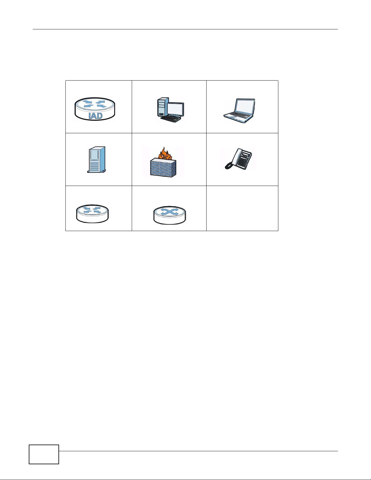
Icons Used in Figures
Figures in this User’s Guide may use the following generic icons. The Device icon is not an exact
representation of your device.
Device Computer Notebook computer
Server Firewall Telephone
Router Switch
6
P-2812HNU(L)-Fx Series User’s Guide

Safety Warnings
Safety Warnings
• Do NOT use this product near water, for example, in a wet basement or near a swimming pool.
• Do NOT expose your device to dampness, dust or corrosive liquids .
• Do NOT store things on the device.
• Do NOT install, use, or service this device during a thunderstorm. There is a remote risk of electric shock
from lightning.
• Connect ONLY suitable accessories to the device.
• Do NOT open the device or unit. Opening or removing covers can expose you to dangerous high voltage
points or other risks. ONLY qualified service personnel should serv ice or disassemble this device. Please
contact your vendor for further information.
• Make sure to connect the cables to the correct ports.
• Place connecting cables carefully so that no one will step on them or stumble over them.
• Always disconnect all cables from this device before servicing or disassembling.
• Use ONLY an appropriate power adaptor or cord for your device.
• Connect the power adaptor or cord to the right supply voltage (for example, 110V AC in North America or
230V AC in Europe).
• Do NOT remove the plug and connect it to a power outlet by itself; always attach the plug to the power
adaptor first before connecting it to a power outlet.
• Do NOT allow anything to rest on the power adaptor or cord and do NOT place the pro duct where an yone can
walk on the power adaptor or cord.
• Do NOT use the devi ce if the power adaptor or cord is damaged as it might cause electrocution.
• If the power adaptor or cord is damaged, remove it from the device and the power source.
• Do NOT attempt to repair the power adaptor or cord. Contact your local vendor to order a new one.
• Do no t use the device outside, and make sure all the connections are indoors. There i s a remote risk of
electric shock from lightning.
• Do NOT obstruct the devi ce ventilation slots, as insufficient airflow may harm your device.
• Use only No. 26 AWG (American Wire Gauge) or larger telecommunication line cord.
• If you wall mount your device, make sure that no electrical lines, gas or water pipes will be damaged.
• This product is for indoor use only (utilisation intérieure exclusivement).
Your product is marked with this symbol, which is known as the WEEE mark. WEEE stands for Waste
Electronics and Electrical Equipment. It means that used electrical and electronic products should not be
mixed with general waste. Used electrical and electronic equipment should be treated separately.
P-2812HNU(L)-Fx Series User’s Guide
7

Safety Warnings
8
P-2812HNU(L)-Fx Series User’s Guide

Contents Overview
Contents Overview
User’s Guide ...........................................................................................................................19
Introduction ................................................................................................................................21
Introducing the Web Configurator ..............................................................................................27
Tutorials .....................................................................................................................................33
Technical Reference ..............................................................................................................79
Connection Status and System Info ...........................................................................................81
Broadband ....................................... ... .... ... ... ... ...........................................................................87
Wireless ...................................................................................................................................123
Home Networking .....................................................................................................................149
Routing .................................. ................................. ................................ ..................................173
Quality of Service (QoS) ................................................. .... ... ... ... .... ... ... ... ... .... ... ... ..................177
Network Address Translation (NAT) ................ ....................................... .................................. 189
Dynamic DNS ...........................................................................................................................197
Firewall ...................................... ................................ ................................... ............................199
MAC Filter ................................................................................................................................205
Parental Control .......................................................................................................................207
Certificates ...............................................................................................................................211
VoIP ..........................................................................................................................................219
Logs ........................................................................................................................................243
Traffic Status ................................ ... ... .... ... ... ... ............................................. .... ... ... ... ...............247
User Account ................................... ... .... ............................................. ... ... ... .... ... ... ..................253
Remote MGMT .........................................................................................................................255
System .....................................................................................................................................257
Time Setting .............................................................................................................................259
Log Setting ..............................................................................................................................261
Firmware Upgrade ...................................................................................................................263
Backup/Restore .................................. .... ... ... ... ... ......................................................................265
Diagnostic ................................................................................................................................269
Troubleshooting .......................................................................................................................273
Product Specifications ..............................................................................................................281
P-2812HNU(L)-Fx Series User’s Guide
9

Contents Overview
10
P-2812HNU(L)-Fx Series User’s Guide

Table of Contents
Table of Contents
About This User's Guide..........................................................................................................3
Document Conventions ...........................................................................................................5
Safety Warnings........................................................................................................................7
Contents Overview...................................................................................................................9
Table of Contents ................................................................................................................... 11
Part I: User’s Guide ................................................................................19
Chapter 1
Introduction.............................................................................................................................21
1.1 Overview ...................................... .... ............................................. ... ... ... .... ... ... ....................21
1.2 Applications for the Device ..................... ... ... .... ... ............................................. ... .... ... ... .......21
1.2.1 Internet Access ....................... ... ... ... ... .............................................. ... ... ... .... ... .......... 21
1.2.2 VoIP Features ........ .... ... ... ... .... ............................................. ... ... ... .... ... ... .................... 22
1.2.3 Wireless Connection ........ ... .... ... ............................................. ... ... .... ... ... ... .... ... ... ... .... 22
1.3 The WLAN Button ........................................ .... ... ... ... .... ... ....................................................23
1.4 Ways to Manage the Device ............................... ... ... .... ... ... ... ............................................. .24
1.5 Good Habits for Managing the Device .................................................................................24
1.6 LEDs (Lights) ..... .... ... ... ... .... ... ... ............................................. .... ... ... ... ... .... ..........................24
1.7 The RESET Button ........................... ... ... ... ... .... ... ... ... .............................................. ... ... .......26
Chapter 2
Introducing the Web Configurator ........................................................................................27
2.1 Overview ...................................... .... ............................................. ... ... ... .... ... ... ....................27
2.1.1 Accessing the Web Configurator ................................................................................27
2.2 The Web Configurator Layout .......... ... ... ... ... .... ... .................................................................29
2.2.1 Title Bar .............. ... .... ... ... ... .............................................. ... ... ... .................................29
2.2.2 Main Window ................................................... .... ... ............................................. ... ....29
2.2.3 Navigation Panel .................................... ....................................................................30
Chapter 3
Tutorials...................................................................................................................................33
3.1 Overview ...................................... .... ............................................. ... ... ... .... ... ... ....................33
3.2 Setting Up Your DSL Connection .................................................. ... ... ... ..............................33
3.3 How to Set up a Wireless Network ............... .... ...... ....... ...... ....... ...... ...... ....... ...... ....... ...... ....36
P-2812HNU(L)-Fx Series User’s Guide
11

Table of Contents
3.3.1 Example Parameters .................................................... ..............................................36
3.3.2 Configuring the AP ............................. .... ... ... ..............................................................36
3.3.3 Configuring the Wireless Client ..................................................................................38
3.4 Setting Up NAT Port Forwarding .. .............................................. .......................................... 43
3.5 How to Make a VoIP Call .....................................................................................................44
3.5.1 VoIP Calls With a Registered SIP Account .................................................................45
3.6 Using the File Sharing Feature .............. ... ... .... ... ... ................................................. ... ... ... ... .47
3.6.1 Set Up File Sharing ....................................................................................................48
3.6.2 Access Your Shared Files From a Computer .............................................................49
3.7 Using the Media Server Feature .........................................................................................49
3.7.1 Configuring the Device ................. ............................................. ... .... ... ... ... .... ... ... ... ... .50
3.7.2 Using Windows Media Player ................. ... ... ... .... ... ... ... .... ..........................................50
3.7.3 Using a Digital Media Adapter ...................................................... .... ... ... ... .... ... ... ... ... .53
3.8 Using the Print Server Feature ............................ ...... ....... ... ....... ...... ...... ....... ...... ....... ...... ....55
3.9 Configuring the MAC Address Filter .....................................................................................70
3.10 Configuring Static Route for Routing to Another Network ..................................................71
3.11 Configuring QoS Queue and Class Setup ..........................................................................73
3.12 Access the Device Using DDNS ........................................................................................76
3.12.1 Registering a DDNS Account on www.dyndns.org ...................................................77
3.12.2 Configuring DDNS on Your Device ...........................................................................77
3.12.3 Testing the DDNS Setting .........................................................................................77
Part II: Technical Reference...................................................................79
Chapter 4
Connection Status and System Info .....................................................................................81
4.1 Overview ...................................... .... ............................................. ... ... ... .... ... ... ....................81
4.2 The Connection Status Screen ............................................................................................81
4.3 The System Info Screen ...................................................................................... .... ... ... ... ....83
Chapter 5
Broadband...............................................................................................................................87
5.1 Overview ...................................... .... ............................................. ... ... ... .... ... ... ....................87
5.1.1 What Yo u Can Do in this Chapter ...............................................................................88
5.1.2 What You Need to Know .. ... .... ... ... ... ... .... ....................................................................88
5.1.3 Before You Begin .................... ....................................................................................91
5.2 The Broadband Screen ........................................................................................................91
5.2.1 Add/Edit Internet Connection ........... ... .... ... ... ................................................. ... ... ... .... 93
5.3 The 3G Backup Screen ... .... ... ... ............................................. .... ... ... ... ... .... ... ... ..................115
5.4 Technical Reference ..................... .... ... ... ... ... .... ................................................ ... .... ...........117
12
P-2812HNU(L)-Fx Series User’s Guide

Table of Contents
Chapter 6
Wireless.................................................................................................................................123
6.1 Overview ...................................... .... ............................................. ... ... ... .... ... ... ..................123
6.1.1 What Yo u Can Do in this Chapter .............................................................................123
6.1.2 Wireless Network Overview .... ... ... ... ... .... ... ... ............................................................123
6.1.3 Before You Begin .................... ... ... ... ... ................................................. ... ... .... ... ........125
6.2 The Wireless General Screen ................................................................... ... ... ... .... ... ... ... ..125
6.2.1 No Security ................................................... ... .... ............................................. ... .....127
6.2.2 Basic (Static WEP/Shared WEP Encryption) .................................................... ........ 127
6.2.3 More Secure (WPA(2)-PSK) .....................................................................................129
6.2.4 WPA(2) Authentication .................................................................. .... ... ... ... .... ... ... ... ..130
6.3 The More AP Screen .................................... .... ... ... ... .... ... ... ... .... ... ... ... ...............................131
6.3.1 Edit More AP ............................. ... ... ............................................. .... ... ... ... .... ... ........132
6.4 The WPS Screen ................ ... ... ... .... ................................................ ... ... ............................133
6.5 The WMM Screen ..............................................................................................................135
6.6 Scheduling Screen ............................................................................................................137
6.7 Technical Reference ..................... .... ... ... ... ... .... ................................................ ... .... ...........137
6.7.1 Additional Wireless Terms ........................................................................................138
6.7.2 Wireless Security Overview ......................................................................................138
6.7.3 Signal Problems .............................. ... .... ... ... ... .... ... ... ... ............................................140
6.7.4 BSS ..........................................................................................................................141
6.7.5 MBSSID ................. .... ... ... ... .... ............................................. ... ... ... .... ........................141
6.7.6 WiFi Protected Setup (WPS) ....................................................................................142
Chapter 7
Home Networking.................................................................................................................149
7.1 Overview ...................................... .... ............................................. ... ... ... .... ... ... ..................149
7.1.1 What Yo u Can Do in this Chapter .............................................................................149
7.1.2 What You Need To Know ................................. .... ... ... ... .... ... ... ... ...............................149
7.2 The LAN Setup Screen ......................................................................................................152
7.3 The Static DHCP Screen .................................................................. ... ... .... ... ... ... .... ... ........153
7.3.1 Before You Begin .................... ... ... ... ................................................. ... ... ..................153
7.4 The UPnP Screen ..............................................................................................................155
7.5 The File Sharing Screen .................. ... ... ... ... .... ... ... ... .... ................................................ ... ..155
7.5.1 Before You Begin .................... ... ... ... ................................................. ... ... ..................156
7.5.2 Add/Edit File Sharing .......................... ................................................. ... ... .... ...........157
7.6 The Media Server Screen ..................................................................................................158
7.7 The Printer Server Screen .................................................................................................159
7.7.1 Before You Begin .................... ... ... ... ................................................. ... ... ..................159
7.8 Technical Reference ..................... .... ... ... ... ... .... ................................................ ... .... ...........160
7.9 Installing UPnP in Windows Example ................................................................................164
7.10 Using UPnP in Windows XP Example .... ... .... ... ... ... .... ... ... ... .... ... ... ... ... .... ... ... ..................167
P-2812HNU(L)-Fx Series User’s Guide
13

Table of Contents
Chapter 8
Routing ..................................................................................................................................173
8.1 Overview ......................................... ... ............................................. ... ... .... ... ... ... .... ...........173
8.2 Configuring Static Route ..................................... ... ... .........................................................174
8.2.1 Add/Edit Static Route ..............................................................................................175
Chapter 9
Quality of Service (QoS).......................................................................................................177
9.1 Overview ...................................... .... ............................................. ... ... ... .... ... ... ..................177
9.1.1 What Yo u Can Do in this Chapter .............................................................................177
9.1.2 What You Need to Know .. ... .... ... ... ... ... .... ... ... ... ................................................. ... ... ..177
9.2 The QoS General Screen ................................... ... ... .... ... ... ... .... ........................................178
9.3 The Queue Setup Screen ..................................................................................................180
9.3.1 Add/Edit a QoS Queue ............................................................................................181
9.4 The Class Setup Screen ..................................................................................................181
9.4.1 Add/Edit QoS Class ........................... .... ... ... ... .........................................................183
9.5 The QoS Monitor Screen ..................................................................................................186
9.6 QoS Technical Reference ..................................................................................................187
9.6.1 IEEE 802.1Q Tag ......................................................................................................187
9.6.2 IP Precedence ................................................. .... ... ... ... ............................................187
9.6.3 DiffServ ........................ ............................................. ... .... ... ... ..................................187
Chapter 10
Network Address Translation (NAT).................................................................................... 189
10.1 Overview .........................................................................................................................189
10.1.1 What You Can Do in this Chapter ...........................................................................189
10.1.2 What You Need To Know ................................................................ ........................ 189
10.2 The Port Forwarding Screen ...........................................................................................190
10.2.1 The Port Forwarding Screen ..................................................................................190
10.2.2 The Port Forwarding Edit Screen ...........................................................................192
10.3 The Sessions Screen ................. .... ... ... ... ... .... ... ... ... ................................................. ... ... ..193
10.4 Technical Reference ................... ....... ...... ....... ...... ... ....... ...... ....... ...... ....... ...... ....... ...... .....193
10.4.1 NAT Definitions .......................................................................................................193
10.4.2 What NAT Does ......................................................................................................194
10.4.3 How NAT Works .....................................................................................................194
Chapter 11
Dynamic DNS ........................................................................................................................197
11.1 Overview .........................................................................................................................197
11.1.1 What You Need To Know ........................................................................................197
11.2 The Dynamic DNS Screen ...............................................................................................197
14
P-2812HNU(L)-Fx Series User’s Guide

Table of Contents
Chapter 12
Firewall .................................................................................................................................. 199
12.1 Overview ..........................................................................................................................199
12.1.1 What You Can Do in this Chapter ...........................................................................199
12.1.2 What You Need to Know ....... ............ ............. ............. ............. ............. .......... ........199
12.2 The General Screen ............ ... ... .... ..................................................................................200
12.3 The Services Screen ......... ... ... ................................................. ... ... ..................................201
12.4 Firewall Technical Reference ........................................................................................... 202
12.4.1 Guidelines For Enhancing Security With Your Firewall ..........................................202
12.4.2 Security Considerations ........................... ....................... ...................... ..................202
Chapter 13
MAC Filter..............................................................................................................................205
13.1 Overview ..........................................................................................................................205
13.1.1 What You Need to Know ....... ............ ............. ............. ............. ............. .......... ........205
13.2 The MAC Filter Screen .....................................................................................................205
Chapter 14
Parental Control.................................................................................................................... 207
14.1 Overview ..........................................................................................................................207
14.2 The Parental Control Screen ............................. ............. ............. ............. ............. ...........207
14.2.1 Add/Edit a Parental Control Rule ............................................................................208
Chapter 15
Certificates............................................................................................................................211
15.1 Overview ..........................................................................................................................211
15.1.1 What You Can Do in this Chapter ...........................................................................211
15.1.2 What You Need to Know ....... ............ ............. ............. ............. ............. .......... ........ 211
15.1.3 Verifying a Certificate ..............................................................................................212
15.2 Local Certificates ..................................... ... .... ... ... ... .... ... ... ... .... ........................................213
15.3 Trusted CA .....................................................................................................................215
15.4 Trusted CA Import ..........................................................................................................215
15.5 View Certificate ................................................................................................................216
Chapter 16
VoIP ........................................................................................................................................219
16.1 Overview ..........................................................................................................................219
16.1.1 What You Can Do in this Chapter ...........................................................................219
16.1.2 What You Need to Know ....... ............ ............. ............. ............. ............. .......... ........219
16.1.3 Before You Begin ....................................................................................................221
16.2 The SIP Service Provider Screen ...................................................................................221
16.3 The SIP Account Screen ..................................................................................................224
16.3.1 Add/Edit SIP Account .............................................................................................226
P-2812HNU(L)-Fx Series User’s Guide
15

Table of Contents
16.4 Multiple SIP Accounts ......................................................................................................228
16.5 The Common Screen .......................................................................................................228
16.6 Phone Screen .................................................................................................................229
16.6.1 Edit Phone Device ..................................................................................................230
16.7 The Phone Region Screen ......... .... ... ... ... ................................................. ... ... ... .... ... ... ... ..231
16.8 The Call Rule Screen .......................................................................................................231
16.9 The FXO Screen (“L” Models Only) .................................................................................233
16.10 Technical Reference ........................ ... ................................................ .... ... ... ... .... ... ... .....233
16.10.1 VoIP ......................................................................................................................234
16.10.2 SIP .......................................................................................................................234
16.10.3 Quality of Service (QoS) .................................. ... ... ... .... ... ... ... ... .... ... ... ... .... ... ... ... ..238
16.10.4 Phone Services Overview ............................... ... ... ... .... ... ... ... ... .... ... ... ... .... ... ... ..... 239
Chapter 17
Logs ......................................................................................................................................243
17.1 Overview .........................................................................................................................243
17.1.1 What You Can Do in this Chapter ...........................................................................243
17.1.2 What You Need To Know ................................................................ ........................ 243
17.2 The System Log Screen ...................................................................................................244
17.3 The Phone Log Screen ............................................... ... ... ... .... ... ... ... ... .... ... ... ..................245
17.4 The VoIP Call History Screen ...........................................................................................245
Chapter 18
Traffic Status .........................................................................................................................247
18.1 Overview ..........................................................................................................................247
18.1.1 What You Can Do in this Chapter ...........................................................................247
18.2 The WAN Status Screen ..................................................................................................247
18.3 The LAN Status Screen ....................................................................................................248
18.4 The NAT Status Screen .................................................................. ... ... .... ... ... ... .... ... ... ... ..249
18.5 The 3G Backup Status Screen ....................................................... .................................. 250
18.6 The VoIP Status Screen ...................................................................................................251
Chapter 19
User Account ........................................................................................................................253
19.1 Overview ..........................................................................................................................253
19.2 The User Account Screen ................. ... ... ... .... ... ... ... .... ... ... ... .... ... ... ... ... .... ........................253
Chapter 20
Remote MGMT.......................................................................................................................255
20.1 Overview ..........................................................................................................................255
20.1.1 What You Need to Know ....... ............ ............. ............. ............. ............. .......... ........255
20.2 The Remote MGMT Screen ....................... .................................................................... ..256
16
P-2812HNU(L)-Fx Series User’s Guide

Table of Contents
Chapter 21
System...................................................................................................................................257
21.1 Overview ..........................................................................................................................257
21.1.1 What You Need to Know ....... ............ ............. ............. ............. ............. .......... ........257
21.2 The System Screen .................... .... ... ... ............................................. ... .... ... .....................257
Chapter 22
Time Setting..........................................................................................................................259
22.1 Overview ..........................................................................................................................259
22.2 The Time Setting Screen ................................................................................................259
Chapter 23
Log Setting ...........................................................................................................................261
23.1 Overview .........................................................................................................................261
23.2 The Log Setting Screen ...................................................................................................261
Chapter 24
Firmware Upgrade ................................................................................................................263
24.1 Overview ..........................................................................................................................263
24.2 The Firmware Upgrade Screen ............................ .................................... ........................ 263
Chapter 25
Backup/Restore ....................................................................................................................265
25.1 Overview ..........................................................................................................................265
25.2 The Backup/Restore Screen ............................................................................................265
25.3 The Reboot Screen ..........................................................................................................267
Chapter 26
Diagnostic ............................................................................................................................. 269
26.1 Overview ..........................................................................................................................269
26.2 The Ping/TraceRoute Screen ..................... .... ............................................. ... ... .... ... ... ... ..269
26.3 The DSL Line Screen .......................................................................................................270
Chapter 27
Troubleshooting.................................................................................................................... 273
27.1 Overview ..........................................................................................................................273
27.2 Power, Hardware Connections, and LEDs ............................... ........................................273
27.3 Device Access and Login .................................................................................................274
27.4 Internet Access ................................................................................................................276
27.5 Wireless Internet Access ..................................................................................................278
27.6 Phone Calls and VoIP ......................................................................................................279
27.7 USB Device Connection ...................................................................................................279
27.8 UPnP ................................................................................................................................279
P-2812HNU(L)-Fx Series User’s Guide
17

Table of Contents
Chapter 28
Product Specifications.........................................................................................................281
Appendix A IP Addresses and Subnetting...........................................................................289
Appendix B Setting Up Your Computer’s IP Address ..........................................................299
Appendix C Pop-up Windows, JavaScript and Java Permissions.......................................329
Appendix D Wireless LANs..................................................................................................339
Appendix E Common Services............................................................................................359
Appendix F IPv6...................................................................................................................363
Appendix G Open Software Announcements......................................................................375
Appendix H Legal Information .............................................................................................411
Index ...................................................................................................................................... 415
18
P-2812HNU(L)-Fx Series User’s Guide

PART I
User’s Guide
19

20

1.1 Overview
The Device is a VDSL, ADSL and Ethernet WAN router, which also includes Voice over IP (VoIP)
communication capabilities to allow you to use a traditional analog telephone to make Internet
calls. By integrating all of these features, you are provided with ease of installation and high-speed,
shared Internet access. The Device is also a complete security solution with a robust firewall based
on Stateful Packet Inspection (SPI) technology and Denial of Service (DoS).
Please refer to the following description of the product name format.
• “H” denotes an integrated 4-port hub (switch).
• “N” denotes wireless functionality, including 802.11n mode. There is an embedded mini-PCI
module for IEEE 802.11 b/g/n wireless LAN connectivity.
• “U” denotes a USB port used to set up a 3G WAN connection via a 3G wireless card or share files
via a USB memory stick or a USB hard drive. The Device can function as a print server with an
USB printer connected.
• “L” denotes the PSTN (Public Switched Telephone Network) line feature. The PSTN line lets you
have VoIP phone service and PSTN phone service at the same time. All PSTN line features
documented in this user’s guide refer to the “L” models only.
CHAPTER 1
Introduction
When the Device does not have power, only the phone connected to the
PHONE port 1 can be used for making calls. Ensure you know which
phone this is, so that in case of emergency you can make outgoing calls.
• Models ending in “1” , for example P-2812HNU(L)-F1, denote a device that works over the analog
telephone system, POTS (Plain Old Telephone Service). Models ending in “3”, for example P2812HNU(L)-F3, denote a device that works over ISDN (Integrated Services Digital Network) or
T-ISDN (UR- 2).
See the chapter on product specifications for a full list of features.
1.2 Applications for the Device
Here are some example uses for which the Device is well suited.
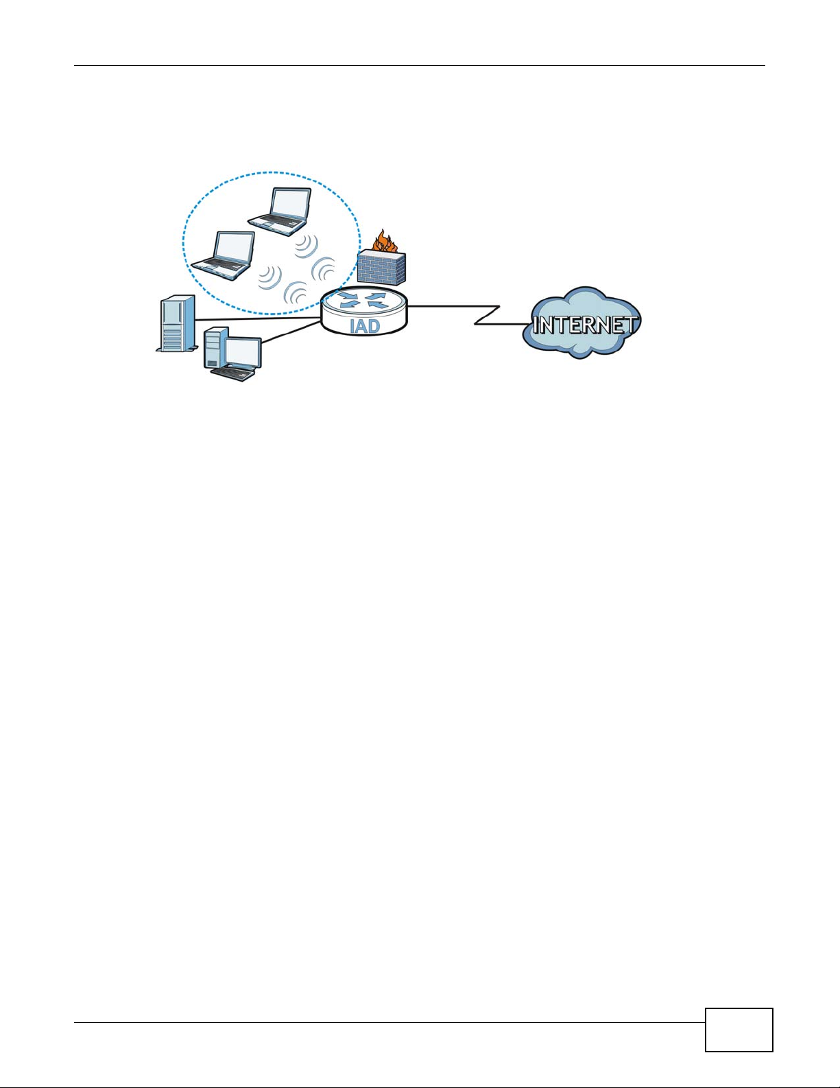
1.2.1 Internet Access
Your Device provides shared Internet access by connecting the DSL port to the DSL or MODEM
jack on a splitter or your telephone jack. If you prefer not to use a DSL line and you have another
broadband modem or router (such as ADSL) available, you can set the WAN mode to EtherWAN in
P-2812HNU(L)-Fx Series User’s Guide 21
Chapter 1 Introduction
the Broadband screen (see Chapter 5 on page 91 for more information) and connect the WAN
port to the broadband modem or router. This way, you can access the Internet via an Ethernet
connection and still use the QoS, Firewall and VoIP functions on the Device.
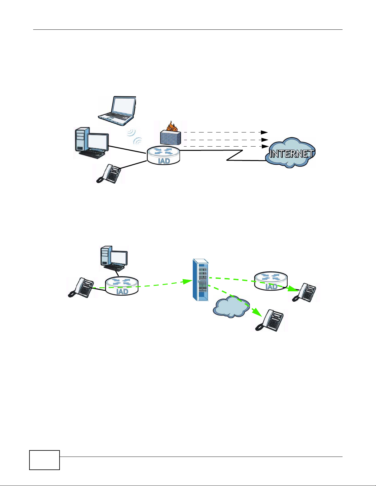
Computers can connect to the Device’s LAN ports (or wirelessly).
Figure 1 Device’s Internet Access Application
LAN
1.2.2 VoIP Features
You can register 1 SIP (Session Initiation Protocol) profile (2 accounts for that profile) and use the
Device to make and receive VoIP telephone calls:
Figure 2 Device’s VoIP Application
WAN
Bridging
IPoE
PPPoE/PPPoA
DSL/Ethernet
The Device sends your call to a VoIP service provider’s SIP server which forwards your calls to
either VoIP or PSTN phones.
1.2.3 Wireless Connection
By default, the wireless LAN (WLAN) is enabled on the Device. Once Wireless is enabled, IEEE
802.11b/g/n compliant clients can wirelessly connect to the Device to access network resources.
22
PSTN
P-2812HNU(L)-Fx Series User’s Guide
Chapter 1 Introduction
You can set up a wireless network with WPS (WiFi Protected Setup) or manually add a client to your
wireless network.
Figure 3 Wireless Connection Application
WLAN
WAN
LAN
1.3 The WLAN Button
You can use the WLAN ON/OFF button on top of the device to turn the wireless LAN on or off. You
can also use it to activate WPS in order to quickly set up a wireless network with strong security.
Turn the Wireless LAN On or Off
1 Make sure the POWER LED is on (not blinking).
2 Press the WLAN ON/OFF button for one second and release it. The WLAN/WPS LED should change
from on to off or vice versa.
Activate WPS
1 Make sure the POWER LED is on (not blinking).
2 Press the WLAN ON/OFF button for more than five seconds and release it. Press the WPS button on
another WPS -enabled device within range of the Device. The WLAN/WPS LED should flash while
the Device sets up a WPS connection with the wireless device.
Note: You must activate WPS in the Device and in another wireless devi c e wi thin two
minutes of each other. See Chapter 6 on page 142 for more information.
P-2812HNU(L)-Fx Series User’s Guide
23
Chapter 1 Introduction
1.4 Ways to Manage the Device
Use any of the following methods to manage the Device.
• Web Configurator. This is recommended for everyday management of the Device using a
(supported) web browser.
• FTP for firmware upgrades and configuration backup/restore.
1.5 Good Habits for Managing the Device
Do the following things regularly to make the Device more secure and to manage the Device more
effectively.
• Change the password. Use a password that’s not easy to guess and that consists of different
types of characters, such as numbers and letters.
• Write down the password and put it in a safe place.
• Back up the configuration (and make sure you know how to restore it). Restoring an earlier
working configuration may be useful if the device becomes unstable or even crashes. If you
forget your password to access the Web Configurator, you will have to reset the Device to its
factory default settings. If you backed up an earlier configuration file, you would not have to
totally re-configure the Device. You could simply restore your last configuration. Keep in mind
that backing up a configuration file will not back up passwords used to set up PPPoE and VoIP.
Write down any information your ISP provides you.
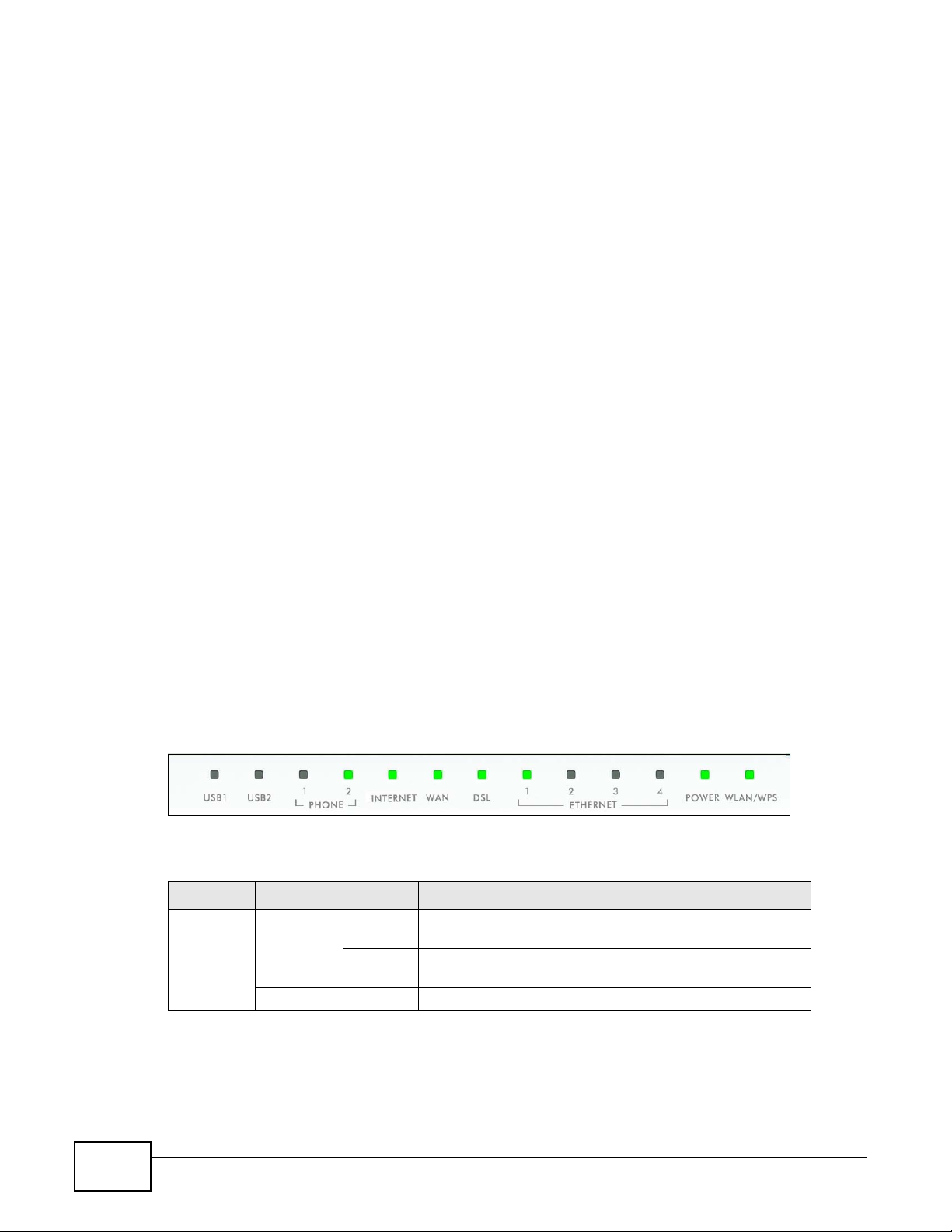
1.6 LEDs (Lights)
The following graphic displays the labels of the LEDs.
Figure 4 LEDs on the Top of the Device
None of the LEDs are on if the Device is not receiving power.
Ta ble 1 LED Descriptions
LED COLOR STATUS DESCRIPTION
USB1-2 Green On The Device recognizes a USB connection but there is no
Off The Device does not detect a USB connection.
traffic.
Blinking The Device is sending/receiving data to /from the USB
device connected to it.
24
P-2812HNU(L)-Fx Series User’s Guide

Chapter 1 Introduction
Ta ble 1 LED Descriptions (continued)
LED COLOR STATUS DESCRIPTION
PHONE1-2 Green On A SIP account is registered for the phone port.
Blinking A telephone connected to the phone port has its receiver off
of the hook or there is an incoming call.
Orange On A SIP account is registered for the phone port and there is a
voice message in the corresponding SIP account.
Blinking A telephone connected to the phone port has its receiver off
Off The phone port does not have a SIP account registered.
INTERNET Green On The Device has an IP connection but no traffic.
Blinking The Device is sending or receiving IP traffic.
Off The Device does not have an IP connection.
Red On The Device attempted to make an IP connection but failed.
WAN Green On This light applies when the Device is in Ethernet WAN mode.
Blinking The Device is sending or receiving data to/from the Ethernet
Off The Device does not have an Ethernet connection with the
DSL Green On The VDSL line is up.
Blinking The Device is initializing the VDSL line.
Orange On The ADSL line is up.
Blinking The Device is initializing the ADSL line.
Off The DSL line is down.
ETHERNET1-4Green
(Giga
Ethernet)
Orange
(Fast
Ethernet)
Off The Device does not have an Ethernet connect ion with the
POWER Green On The Device is receiving power and ready for use.
Red On The Device detected an error while self-testing, or there is a
Off The Device is not receiving power.
On The Device has a successful 1000 Mbps Ethernet connection
Blinking The Device is sending or receiving data to/from the LAN at
On The Device has a successful 10/100 Mbps Ethernet
Blinking The Device is sending or receiving data to/from the LAN at
Blinking The Device is self-testing.
of the hook and there is a voice message in the
corresponding SIP account.
Your device has a WAN IP address (either static or assigned
by a DHCP server), PPP negotiation was successfully
completed (if used).
Possible causes are no response from a DHCP server, no
PPPoE response, PPPoE authentication failed.
The Device has an Ethernet connection with a device on the
WAN.
WAN.
WAN.
with a device on the Local Area Network (LAN).
1000 Mbps.
connection with a device on the Local Area Network (LAN).
10/100 Mbps.
LAN.
device malfunction.
P-2812HNU(L)-Fx Series User’s Guide
25

Chapter 1 Introduction
Ta ble 1 LED Descriptions (continued)
LED COLOR STATUS DESCRIPTION
WLAN/WPS Green On The wireless network is activated and is operating in IEEE
Blinking The Device is communicating with other wireless clients.
Orange On The WPS is configured.
Blinking The Device is setting up a WPS connection.
Off The wireless network is not activated.
Refer to the Quick Start Guide for information on hardware connections.
1.7 The RESET Button
If you forget your password or cannot access the web configurator, you will need to use the RESET
button at the back of the device to reload the factory-default configuration file. This means that y ou
will lose all configurations that you had previously and the passwords will be reset to the defaults.
1 Make sure the POWER LED is on (not blinking).
802.11 “b”, “g” or “n” mode.
2 T o set the device back to the factory default settings, press the RESET button for 5 seconds or until
the POWER LED begins to blink and then release it. When the POWER LED begins to blink, the
defaults have been restored and the device restarts.
26
P-2812HNU(L)-Fx Series User’s Guide

2.1 Overview
The web configurator is an HTML-based management interface that allows easy device setup and
management via Internet browser. Use Internet Explorer 6.0 and later versions, Mozilla Firefox 3
and later versions, or Safari 2.0 and later versions. The recommended screen resolution is 1024 by
768 pixels.
In order to use the web configurator you need to allow:
• Web browser pop-up windows from your device. Web pop-up blocking is enabled by default in
Windows XP SP (Service Pack) 2.
• JavaScript (enabled by default).
• Java permissions (enabled by default).
CHAPTER 2
Introducing the Web Configurator
See Appendix C on page 329 if you need to make sure these functions are allowed in Internet
Explorer.
2.1.1 Accessing the Web Configurator
1 Make sure your Device hardware is properly connected (refer to the Quick Start Guide).
2 Launch your web browser.
3 Type "192.168.1.1" as the URL.
4 A password screen displays. Type “admin” as the default Username and “1234” as the default
password to access the device’s W eb Configur ator. Click Login. If you have changed the password,
enter your password and click Login.
Figure 5 Password Screen
P-2812HNU(L)-Fx Series User’s Guide 27
Chapter 2 Introducing the Web Configurator
Note: For security reasons, the Device automatically logs you out if you do not use the
web configurator for five minutes (default). If this happens, log in again.
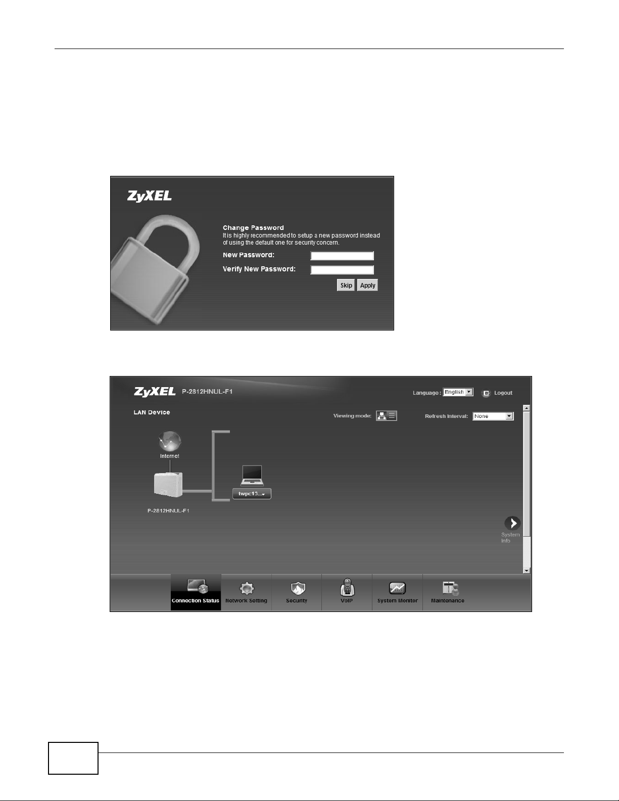
5 The following screen displays if you have not yet changed your password. It is strongly
recommended you change the default password. Enter a new password, retype it to confirm and
click Apply; alternatively click Skip to proceed to the main menu if you do not want to change the
password now.
Figure 6 Change Password Screen
6 The Connection Status screen appears.
Figure 7 Connection Status
7 Click System Info to display the System Info screen, where you can view the Device’s interface
and system information.
28
P-2812HNU(L)-Fx Series User’s Guide
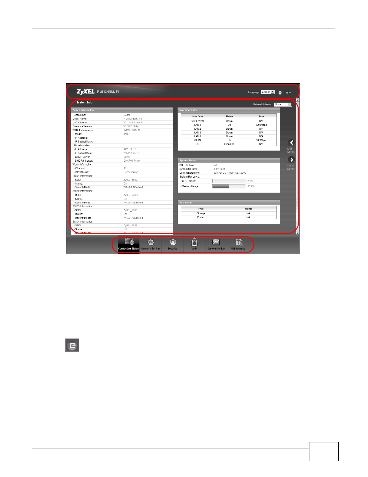
2.2 The Web Configurator Layout
Click Connection Status > System Info to show the following screen.
Figure 8 Web Configurator Layout
A
B
Chapter 2 Introducing the Web Configurator
a
b
C
As illustrated above, the main screen is divided into these parts:
• A - title bar
• B - main window
• C - navigation panel
2.2.1 Title Bar
The title bar shows the following icon in the upper right corner.
Click this icon to log out of the web configurator.
2.2.2 Main Window
The main window displays information and configuration fields. It is discussed in the rest of this
document.
After you click System Info on the Connection Status screen, the System Info screen is
displayed. See Chapter 4 on page 83 for more information about the System Info screen.
P-2812HNU(L)-Fx Series User’s Guide
29
Chapter 2 Introducing the Web Configurator
If you click LAN Device on the System Info screen (a in Figure 8 on page 29), the Connection
Status screen appears. See Chapter 4 on page 81 for more information about the Connection
Status screen.
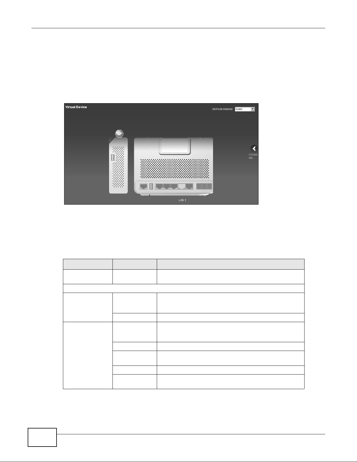
If you click Virtual Device on the System Info screen (b in Figure 8 on page 29), a visual graphic
appears, showing the connection status of the Device’s ports. The connected ports are in color and
disconnected ports are gray.
Figure 9 Virtual Device
2.2.3 Navigation Panel
Use the menu items on the navigation panel to open screens to configure Device features. The
following table describes each menu ite m.
Ta ble 2 Navigation Panel Summary
LINK TAB FUNCTION
Connection Status This screen shows the network status of the Device and
Network Setting
Broadband Broadband Use this screen to view and modify your WAN interface. You
3G Backup Use this screen to configure the 3G WAN connection.
Wireless General Use this screen to turn the wireless connection on or off,
More AP Use this screen to configure multiple BSSs on the Device.
WPS Use this screen to use WPS (Wi-Fi Protected Setup) to
WMM Use this screen to enable or disable Wi-Fi MultiMedia (WMM).
Scheduling Use this screen to configure when the Device enables or
computers/devices connected to it.
can also configure ISP parameters, WAN IP address
assignment, DNS servers and other advanced properties.
specify the SSID(s) and configure the wireless LAN settings
and WLAN authentication/security settings.
establish a wireless connection.
disables the wireless LAN.
30
P-2812HNU(L)-Fx Series User’s Guide
 Loading...