

Page 1
P-2601HN(L)-F1 Series
Firmware Version 3.10
Edition 1, 10/2010
ADSL2+ IAD with 802.11n Wireless
Default Login Details
IP Address http://192.168.1.1
User Name admin
Password 1234
www.zyxel.com
www.zyxel.com
Copyright © 2010
ZyXEL Communications Corporation
Page 2

Page 3
About This User's Guide
About This User's Guide
Intended Audience
This manual is intended for people who want to configure the Zy XEL Device using
the web configurator.
Related Documentation
•Quick Start Guide
The Quick Start Guide is designed to help you get up and running right away. It
contains information on setting up your network and configuring for Internet
access.
• Support Disc
Refer to the included CD for support documents.
Documentation Feedback
Send your comments, questions or suggestions to: techwriters@zyxel.com.tw
Thank you!
The Technical Writing Team, ZyXEL Communications Corp.,
6 Innovation Road II, Science-Based Industrial Park, Hsinchu, 30099, Taiwan.
Need More Help?
More help is available at www.zyx el.com.
P-2601HN(L)-F1 Series User’s Guide
3
Page 4

About This User's Guide
• Download Library
Search for the latest product updates and documentation from this link. Read
the Tech Doc Overview to find out how to efficiently use the User Guide, Quick
Start Guide and Command Line Interface Reference Guide in order to better
understand how to use your product.
• Knowledge Base
If you have a specific question about your product, the answer may be here.
This is a collection of answers to previously asked questions about ZyXEL
products.
•Forum
This contains discussions on ZyXEL prod ucts. Learn from others who use ZyXEL
products and share your experiences as well.
Customer Support
Should problems arise that cannot be solved by the methods listed above, you
should conta ct your vendor. If you ca nnot contact your vendor, then cont act a
ZyXEL office for the region in which you bought the device.
See http://www.zyxel.com/web/contact_us.php for contact information. Please
have the following informatio n ready when you contact an office.
• Product model and serial number.
•Warranty Information.
• Date that you received your device.
• Brief description of the problem and the steps you took to solve it.
4
P-2601HN(L)-F1 Series User’s Guide
Page 5

Document Conventions
Document Conventions
Warnings and Notes
These are how warnings and notes are shown in this User’s Guide.
Warnings tell you about things that could harm you or your device.
Note: Notes tell you other important information (for example, other things you may
need to configure or helpful tips) or recommendations.
Syntax Conventions
• The P-2601HN(L)-F1 series may be referred to as the “ZyXEL Device”, the
“device”, the “system” or the “product” in this User’s Guide.
• Product labels, screen names, field labels and field choices are all in bold font.
• A key stroke is denoted by square brackets and uppercase text, for example,
[ENTER] means the “enter” or “ret urn” key on your keyboard.
• “Enter” means for you to type one or more characters and then press the
[ENTER] key. “Select” or “choose” means for you to use one of the predefined
choices.
• A right angle bracket ( > ) within a screen name denotes a mouse click. For
example, Maintenance > Log > Log Setting means you first click
Maintenance in the navigation panel, then the Log sub menu and finally the
Log Setting tab to get to that screen.
• Units of measurement may denote the “metric” value or the “scientific” value.
For example, “k” for kilo may denote “1000” or “1024”, “M” for mega may
denote “1000000” or “1048576” and so on.
• “e.g.,” is a shorthand for “for instance”, and “i.e.,” means “that is” or “in other
words”.
P-2601HN(L)-F1 Series User’s Guide
5
Page 6
Document Conventions
Icons Used in Figures
Figures in this User’s Guide may use the following generic icons. The Z yXEL Device
icon is not an exact representation of your device.
ZyXEL Device Computer Notebook computer
Server Telephone Firewall
Switch Router
6
P-2601HN(L)-F1 Series User’s Guide
Page 7

Safety Warnings
Safety Warnings
• Do NOT use this product near water, for example, in a wet basement or near a swimming
pool.
• Do NOT expose your device to dampness, dust or corrosive liquids.
• Do NOT store things on the device.
• Do NOT install, use, or service this device during a thunderstorm. There is a remote risk
of electric shock from lightning.
• Connect ONLY suitable accessories to the device.
• Do NOT open the device or unit. Opening or removing covers can expose you to
dangerous high voltage points or other risks. ONLY qualified service personnel should
service or disassemble this device. Please contact your vendor for further information.
• Make sure to connect the cables to the correct ports.
• Place connecting cables carefully so that no one will step on them or stumble over them.
• Always disconnect all cables from this device before servicing or disassembling.
• Use ONLY an appropriate power adaptor or cord for your device.
• Connect the power adaptor or cord to the right supply voltage (for example, 110V AC in
North America or 230V AC in Europe).
• Do NOT allow anything to rest on the power adaptor or cord and do NOT place the
product where anyone can walk on the power adaptor or cord.
• Do NOT use the device if the power adaptor or cord is damaged as it might cause
electrocution.
• If the power adaptor or cord is damaged, remove it from the device and the power
source.
• Do NOT attempt to repair the power adaptor or cord. Contact your local vendor to order a
new one.
• Do not use the device outside, and make sure all the connections are indoors. There is a
remote risk of electric shock from lightning.
• Do NOT obstruct the device ventilation slots, as insufficient airflow may harm your
device.
• Use only No. 26 AWG (American Wire Gauge) or larger telecommunication line cord.
• Antenna Warning! This device meets ETSI and FCC certification requirements when using
the included antenna(s). Only use the included antenna(s).
• This CPE is indoor use only. (Utilisation intérieure exclusivement.)
Your product is marked with this symbol, which is known as the WEEE mark. WEEE
stands for Waste Electronics and Electrical Equipment. It means that used electrical
and electronic products should not be mixed with general waste. Used electrical and
electronic equipment should be treated separately.
P-2601HN(L)-F1 Series User’s Guide
7
Page 8

Safety Warnings
8
P-2601HN(L)-F1 Series User’s Guide
Page 9

Contents Overview
Contents Overview
User’s Guide ........................................................................................................ ...................19
Introducing the ZyXEL Device ...................................................................................................21
Introducing the Web Configurator .............................................................................................. 27
Tutorials ..................................................................................................................................... 35
Technical Reference ..............................................................................................................59
Connection Status and System Info Screens ............................................................................ 61
Broadband ................................................................................................................................. 67
Wireless .................................... ....................................................... .......................................... 81
Home Networking .....................................................................................................................111
Routing ....................................................................................................................................127
DNS Route ............................................ ... ... .... ............................................. ... ... .... ... ... ........... 131
Quality of Service (QoS) ............................................................................ ... ... ... ..................... 135
Network Address Translation (NAT) ........................................................................................ 149
Dynamic DNS .......................................................................................................................... 157
Firewall .................................................................................................................................... 159
MAC Filter ................................................................................................................................ 165
Certificates ................................... ....................... ....................... ...................... ........................ 167
VoIP ......................................................................................................................................... 175
Logs ........................................................................................................................................203
System Monitor .................. ... ... ............................................. .... ... ... ... ... .... ... ... ... .... .................207
User Account ...................................... ... ... ............................................. .... ... ... ... .... ... ..............213
Remote MGMT ........................................................................................................................ 215
SNMP ...................................................................................................................................... 217
System ................................... ...................... ....................... ....................... .............................. 221
Time Setting ............................................................................................................................. 223
Log Setting ............................................................................................................................. 225
Firmware Upgrade ................................................................................................................... 227
Backup/Restore ....................................................................................................................... 229
Diagnostic .................................... ....................................................... ..................................... 233
Troubleshooting ..................................................... .................................................................. 237
Product Specifications ............................................................................................................. 243
P-2601HN(L)-F1 Series User’s Guide
9
Page 10

Contents Overview
10
P-2601HN(L)-F1 Series User’s Guide
Page 11

Table of Contents
Table of Contents
About This User's Guide..........................................................................................................3
Document Conventions............................................................................................................5
Safety Warnings ........................................................................................................................7
Contents Overview ...................................................................................................................9
Table of Contents....................................................................................................................11
Part I: User’s Guide................................................................................ 19
Chapter 1
Introducing the ZyXEL Device...............................................................................................21
1.1 Overview ............. ............................................. ... .... ... ... ... .... ................................................ 21
1.2 Applications for the ZyXEL Device ...................................................................................... 22
1.2.1 Internet Access ................................................ ... ... .... ............................................. ...22
1.2.2 Internet Calls (VoIP) ................................................................................................... 22
1.2.3 Wireless Connection ........... ... ... ... .............................................. ... ... ... .... ... ... ... ... .... ... 23
1.3 Ways to Manage the ZyXEL Device ................... .... ... ... ... .... ... ............................................. 23
1.4 Good Habits for Managing the ZyXEL Device .....................................................................24
1.5 LEDs (Lights) ......................... .... ... ... ............................................. ... .... ... ... ... .... ... ................ 24
1.6 The RESET Button ............................. ... .... ... ... ............................................. .... ... ... ... ... ....... 25
1.7 The WIRELESS ON/OFF Button ......................................................................................... 26
Chapter 2
Introducing the Web Configurator ........................................................................................27
2.1 Overview ............. ............................................. ... .... ... ... ... .... ................................................ 27
2.1.1 Accessing the Web Configurator ................................................................................ 27
2.2 The Web Configurator Layout .............................................. ... ... ... ... .... ... ... ... .... ... ... ............. 30
2.2.1 Title Bar .................................. ... ............................................. .... ... ... .......................... 31
2.2.2 Main Window .......................... ... ............................................. .... ... ... ... .... ... ... .............31
2.2.3 Navigation Panel .......... .... ... ... ... ................................................................................. 31
2.2.4 Status Bar ............................................... ... .............................................. ... ................ 34
Chapter 3
Tutorials...................................................................................................................................35
3.1 Overview ............. ............................................. ... .... ... ... ... .... ................................................ 35
P-2601HN(L)-F1 Series User’s Guide
11
Page 12

Table of Contents
3.2 Setting Up Your DSL Connection ................................. ................................................ .... ... 35
3.3 How to Set up a Wireless Network ...................................................................................... 38
3.3.1 Example Parameters ........................... ... ... .... ... ... ... .... ... ............................................. 38
3.3.2 Configuring the AP ....... .... ... ... ... ... .... .......................................................................... 38
3.3.3 Configuring the Wireless Client .................................................................................. 40
3.4 Setting Up NAT Port Forwarding ......................................................................................... 45
3.5 How to Make a VoIP Call .....................................................................................................47
3.5.1 VoIP Calls With a Registered SIP Account ................................................................ 47
3.6 Configuring the MAC Address Filter .................................................................................... 50
3.7 Configuring Static Route for Routing to Another Network ................................................... 51
3.8 Configuring QoS Queue and Class Setup ...........................................................................53
3.9 Access the ZyXEL Device Using DDNS .............................................................................. 56
3.9.1 Registering a DDNS Account on www.dyndns.org .................................................... 57
3.9.2 Configuring DDNS on Your ZyXEL Device ................................................................. 57
3.9.3 Testing the DDNS Setting ................................... ... ............................................. .... ... 58
Part II: Technical Reference.................................................................. 59
Chapter 4
Connection Status and System Info Screens.......................................................................61
4.1 Overview ............. ............................................. ... .... ... ... ... .... ................................................ 61
4.2 The Connection Status Screen ............................................................................................ 61
4.3 The System Info Screen .. ... ... .... ... ... ... ... .... ... ... ... .... ................................................ ... ... .... ... 63
Chapter 5
Broadband...............................................................................................................................67
5.1 Overview ............. ............................................. ... .... ... ... ... .... ................................................ 67
5.1.1 What You Need to Know ..... ... ... ... .... .......................................................................... 67
5.1.2 Before You Begin ............................................. ... ... .... ... ... ... ... .... ... ... .......................... 68
5.2 The Broadband Screen .......................................................................................................69
5.2.1 Add/Edit Broadband ......... ... ... ... ... .... ... ... ... .... ... ................................................ ... .... ... 70
5.3 Technical Reference ..................... ... ... ... .... .......................................................................... 76
5.3.1 Encapsulation ................... ... ... ... ... .............................................. ... ... ... .... ... ... .............76
5.3.2 Multiplexing ......... ... ... ... .... ... ... ... ............................................. .... ... ... ... .... ... ................77
5.3.3 VPI and VCI ........................................................ ... .... ... ... .......................................... 77
5.3.4 IP Address Assignment .......................................... .... ... ... .......................................... 77
5.3.5 NAT .............................................. .... ... ............................................. ... ....................... 78
5.4 Traffic Shaping ....................................... .... ... ... ... .... ... ... ... .................................................... 78
5.4.1 ATM Traffic Classes ...................................................................................................79
Chapter 6
Wireless...................................................................................................................................81
12
P-2601HN(L)-F1 Series User’s Guide
Page 13

Table of Contents
6.1 Overview ............. ............................................. ... .... ... ... ... .... ................................................ 81
6.1.1 What Yo u Can Do in this Chapter .............................................................................. 81
6.1.2 Wireless Network Overview ... ... ... .... ... ... ... .... ... ... ............................................. ... .... ... 81
6.1.3 Before You Begin ............................................. ... ... .... ... ... ... ... .... ... ... .......................... 83
6.2 The Wireless General Screen .................................................. ... ... .................................... 83
6.2.1 No Security .......................... ... ............................................. ... .... ... ... ... .... ................... 85
6.2.2 Basic (Static WEP/Shared WEP Encryption) ............................................................. 86
6.2.3 More Secure (WPA(2)-PSK) ......................................................................................88
6.2.4 WPA(2) Authentication .............................. .... ... ... ... .... ... ... ... ... .................................... 89
6.3 The More AP Screen ....................................... ... .... ... ... ... .... ... ... ... ... .... ... ............................. 91
6.3.1 Edit More AP ....... ... ... ... .... ... ............................................. ... ... .... ... ... ... .... ................... 92
6.4 The WPS Screen ................................... .... ................................................ ... .... ................... 93
6.5 The WMM Screen ................................................................................................................95
6.6 Scheduling Screen ............................................................................................................. 97
6.7 Technical Reference ..................... ... ... ... .... ... ....................................................................... 97
6.7.1 Additional Wireless Terms .......................................................................................... 98
6.7.2 Wireless Security Overview ....................................................................................... 98
6.7.3 Signal Problems ........ ... .... ... ... ... ... .... ........................................................................ 101
6.7.4 BSS ..........................................................................................................................101
6.7.5 MBSSID .............................................. ... ... .............................................. ... ... ... ........102
6.7.6 WiFi Protected Setup (WPS) .................................................................................... 103
Chapter 7
Home Networking .................................................................................................................111
7.1 Overview ............. ............................................. ... .... ... ... ... .... ...............................................111
7.1.1 What Yo u Can Do in this Chapter .............................................................................111
7.1.2 What You Need To Know ................................. ... ... ................................................... 111
7.2 The LAN Setup Screen .......................................................................................................113
7.3 The Static DHCP Screen .............................. ... ... .... ... ... ... ................................................. ..114
7.3.1 Before You Begin ............................................. ... ... .... ... ... ... ... .... ... ... .........................115
7.4 The UPnP Screen ...............................................................................................................116
7.5 Technical Reference ..................... ... ... ... .... ... ......................................................................117
7.6 Installing UPnP in Windows Example .................................................................................119
7.7 Using UPnP in Windows XP Example ............................................................................... 122
Chapter 8
Routing ..................................................................................................................................127
8.1 Overview ............... ............................................. .... ... ... ... .... ... ........................................... 127
8.2 Configuring Static Route .................................................. .... ... ... ... ... .... ... ... ... .... .................128
8.2.1 Add/Edit Static Route ............................................................................................. 129
Chapter 9
DNS Route.............................................................................................................................131
P-2601HN(L)-F1 Series User’s Guide
13
Page 14

Table of Contents
9.1 Overview ............. ............................................. ... .... ... ... ... .... .............................................. 131
9.2 The DNS Route Screen .....................................................................................................132
9.2.1 Add/Edit DNS Route Edit ................... ... ... .... ... ... ................................................ .... . 132
Chapter 10
Quality of Service (QoS).......................................................................................................135
10.1 Overview .......................................................................................................................... 135
10.1.1 What You Can Do in this Chapter .......................................................................... 135
10.1.2 What You Need to Know ........................................................................................ 136
10.2 The QoS General Screen ............................................................................................... 136
10.3 The Queue Setup Screen ................................................................................................ 138
10.3.1 Add/Edit a QoS Queue .......................................................................................... 139
10.4 The Class Setup Screen ................................................................................................ 140
10.4.1 Add/Edit QoS Class ..............................................................................................142
10.5 The QoS Monitor Screen ................................................................................................ 145
10.6 QoS Technical Reference ................................................................................................146
10.6.1 IEEE 802.1Q Tag ................................................................................................... 146
10.6.2 IP Precedence ........................................................................................................ 147
10.6.3 DiffServ ................................................................................................................. 147
Chapter 11
Network Address Translation (NAT)....................................................................................149
11.1 Overview .........................................................................................................................149
11.1.1 What You Can Do in this Chapter ......................................... .................................. 149
11.1.2 What You Need To Know ........................................................................................ 149
11.2 The Port Forwarding Screen ........................................................................................... 150
11.2.1 The Port Forwarding Screen .................................................................................. 151
11.2.2 The Port Forwarding Edit Screen ........................................................................... 152
11.3 The Sessions Screen .......................................................................................................153
11.4 Technical Reference ........................................................................................................ 154
11.4.1 NAT Definitions .......................................................................................................154
11.4.2 What NAT Does ......................................................................................................155
11.4.3 How NAT Works ..................................................................................................... 155
Chapter 12
Dynamic DNS ........................................................................................................................157
12.1 Overview ......................................................................................................................... 157
12.1.1 What You Need To Know ....................................................................................... 157
12.2 The Dynamic DNS Screen ................................................ ... ... ... ... .... ... ... ... .... ... ... ........... 1 58
Chapter 13
Firewall...................................................................................................................................159
13.1 Overview .......................................................................................................................... 159
14
P-2601HN(L)-F1 Series User’s Guide
Page 15

Table of Contents
13.1.1 What You Can Do in this Chapter .......................................................................... 159
13.1.2 What You Need to Know ........................................................................................ 160
13.2 The General Screen ............... ...... ... ...............................................................................161
13.3 The Services Screen ........... .... ... ................................................ ... .... ..............................161
13.4 Firewall Technical Reference ................... .......................... ......................... ..................... 163
13.4.1 Guidelines For Enhancing Security With Your Firewall .......................................... 163
13.4.2 Security Considerations ......................................................................................... 163
Chapter 14
MAC Filter..............................................................................................................................165
14.1 Overview .......................................................................................................................... 165
14.1.1 What You Need to Know ........................................................................................ 165
14.2 The MAC Filter Screen .................................................................................................... 166
Chapter 15
Certificates ............................................................................................................................167
15.1 Overview .......................................................................................................................... 167
15.1.1 What You Can Do in this Chapter .......................................................................... 167
15.1.2 What You Need to Know ........................................................................................ 167
15.1.3 Verifying a Certificate ............................................................................................. 169
15.2 Local Certificates ............................................................................................................. 170
15.3 Trusted CA ..................................................................................................................... 172
15.4 Trusted CA Import ......................................................................................................... 173
15.5 View Certificate ................................................................................................................ 173
Chapter 16
VoIP ........................................................................................................................................175
16.1 Overview .......................................................................................................................... 175
16.1.1 What You Can Do in this Chapter .......................................................................... 175
16.1.2 What You Need to Know ........................................................................................ 176
16.1.3 Before You Begin ................................................................................................... 177
16.2 The SIP Service Provider Screen ................................................................................... 177
16.3 The SIP Account Screen ................................................................................................. 181
16.3.1 Add/Edit SIP Account .............................................................................................183
16.4 The SIP Common Screen ................................................................................................186
16.5 The Phone Device Screen .............................................................................................. 187
16.5.1 Edit Phone Device .................................................................................................. 187
16.6 The Region Screen ....................... ... ... .... ... ... ................................................. ... ... ...........188
16.7 The Call Rule Screen ......................................................................................................189
16.8 The FXO Screen (“L” Models Only) ................................................................................. 190
16.9 Technical Reference ........................................................................................................ 191
16.9.1 VoIP ........................................................................................................................ 191
16.9.2 SIP ........................................................................................................................ 192
P-2601HN(L)-F1 Series User’s Guide
15
Page 16

Table of Contents
16.9.3 Quality of Service (QoS) ........................................................................................ 197
16.9.4 Phone Services Overview ...................................................................................... 198
Chapter 17
Logs ......................................................................................................................................203
17.1 Overview ......................................................................................................................... 203
17.1.1 What You Can Do in this Chapter .......................................................................... 203
17.2 The Phone Log Screen ..................... ... .... ... ... ... ................................................. ... ... ........203
17.3 The VoIP Call History Screen .......................................................................................... 204
Chapter 18
System Monitor ....................................................................................................................207
18.1 Overview .......................................................................................................................... 207
18.1.1 What You Can Do in this Chapter .......................................................................... 207
18.2 The WAN Status Screen .................................................................................................. 207
18.3 The LAN Status Screen ................................................................................................... 208
18.4 The NAT Status Screen ................................................................................................... 209
18.5 The VoIP Status Screen .................................................................................................. 210
Chapter 19
User Account.........................................................................................................................213
19.1 Overview .......................................................................................................................... 213
19.2 The User Account Screen ................................................. ... ... ... ... .... ... ... ... .... ... ... ........... 2 13
Chapter 20
Remote MGMT.......................................................................................................................215
20.1 Overview .......................................................................................................................... 215
20.1.1 What You Need to Know ........................................................................................ 215
20.2 The Remote MGMT Screen ............................................................................................ 216
Chapter 21
SNMP......................................................................................................................................217
21.1 Overview .......................................................................................................................... 217
21.2 The SNMP Screen ...........................................................................................................217
Chapter 22
System...................................................................................................................................221
22.1 Overview .......................................................................................................................... 221
22.1.1 What You Need to Know ........................................................................................ 221
22.2 The System Screen .........................................................................................................221
Chapter 23
Time Setting ..........................................................................................................................223
16
P-2601HN(L)-F1 Series User’s Guide
Page 17

Table of Contents
23.1 Overview .......................................................................................................................... 223
23.2 The Time Setting Screen ................................................................................................ 223
Chapter 24
Log Setting ...........................................................................................................................225
24.1 Overview ......................................................................................................................... 225
24.2 The Log Setting Screen ................................................................................................... 225
Chapter 25
Firmware Upgrade ................................................................................................................227
25.1 Overview .......................................................................................................................... 227
25.2 The Firmware Upgrade Screen ....................................................................................... 227
Chapter 26
Backup/Restore.....................................................................................................................229
26.1 Overview .......................................................................................................................... 229
26.2 The Backup/Restore Screen ........................................................................................... 229
26.3 The Reboot Screen .........................................................................................................231
Chapter 27
Diagnostic..............................................................................................................................233
27.1 Overview .......................................................................................................................... 233
27.1.1 What You Can Do in this Chapter .......................................................................... 233
27.2 The Ping Screen ..............................................................................................................233
27.3 The DSL Line Screen ......................................................................................................234
Chapter 28
Troubleshooting....................................................................................................................237
28.1 Overview .......................................................................................................................... 237
28.2 Power, Hardware Connections, and LEDs .............................. ... ... .... ... ... ... .... ... ... ... ........237
28.3 ZyXEL Device Access and Login .................................................................................... 238
28.4 Internet Access ................................................................................................................ 240
28.5 Phone Calls and VoIP ......................................................................................................241
28.6 Wireless LAN Troubleshooting ........................................................................................ 242
Chapter 29
Product Specifications.........................................................................................................243
Appendix A IP Addresses and Subnetting ...........................................................................253
Appendix B Setting Up Your Computer’s IP Address...........................................................265
Appendix C Pop-up Windows, JavaScript and Java Permissions........................................291
Appendix D Wireless LANs..................................................................................................299
P-2601HN(L)-F1 Series User’s Guide
17
Page 18

Table of Contents
Appendix E Common Services.............................................................................................323
Appendix F Open Software Announcements.......................................................................327
Appendix G Legal Information..............................................................................................333
Index.......................................................................................................................................337
18
P-2601HN(L)-F1 Series User’s Guide
Page 19

PART I
User’s Guide
19
Page 20

20
Page 21

CHAPTER 1
Introducing the ZyXEL Device
1.1 Overview
The ZyXEL Device is an ADSL2+ Integrated Access Device (IAD) that combines an
ADSL2+ router with Voice over IP (VoIP) communication capabilities to allow you
to use a traditional analog telephone to make Internet calls. By integrating DSL
and NAT, you are provided with ease of installation and high- speed, shared
Internet access. The ZyXEL Device is also a c om p l et e security solution with a
robust firewall and content filtering.
You can use Quality of Service (QoS) to ef ficiently manage tr affic on your network
by giving priority to certain types of traffic and/or to particular computers.
Please refer to the following description of the product name format.
• “H” denotes an integrated 4-port hu b (switch).
• “N” denotes wireless functionality, including 802.11n mode. There is an
embedded USB module for IEEE 802.11b/g/n wireless LAN connectivity.
Only use firmware for your ZyXEL Device’s specific model. Refer
to the label on the bottom of your ZyXEL Device.
• “L” denotes the PSTN (Public Switched Telephone Network) line feature. The
PSTN line lets you have V oIP phone service and PSTN phone service at the same
time. All PSTN line features documented in this user’s guide refer to the “L”
models only.
When the ZyXEL Device does not have power, only the phone with
lifeline connected to the FXO port can be used for making calls.
• Models ending in “1” denote a device that works over the analog telephone
system, POTS (Plain Old Telephone Service).
See the chapter on product specifications for a full list of features.
P-2601HN(L)-F1 Series User’s Guide
21
Page 22
Chapter 1 Introducing the ZyXEL Device
LAN
PPPoE
IPoE
Bridging
WAN
ADSL
1.2 Applications for the ZyXEL Device
Here are some example uses for which the ZyXEL Device is well suited.
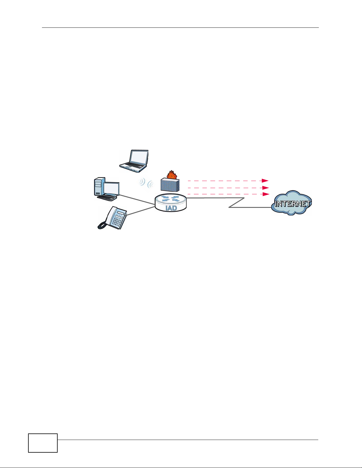
1.2.1 Internet Access
Your ZyXEL Device provides shared Internet access by connecting the DSL port to
the DSL or MODEM jack on a splitter or your telephone jack. Computers can
connect to the ZyXEL Device’s LAN ports (or wirelessly).
Figure 1 ZyXEL Device’s Internet Access Application
You can also configure firewall on the ZyXEL Device for secure Internet access.
When the firewall is on, all inc o m ing traffic from the Internet to your network is
blocked unless it is initia t e d fr om your network. This means that probes from the
outside to your network are not allowed, but you can safely browse the Internet
and download files.
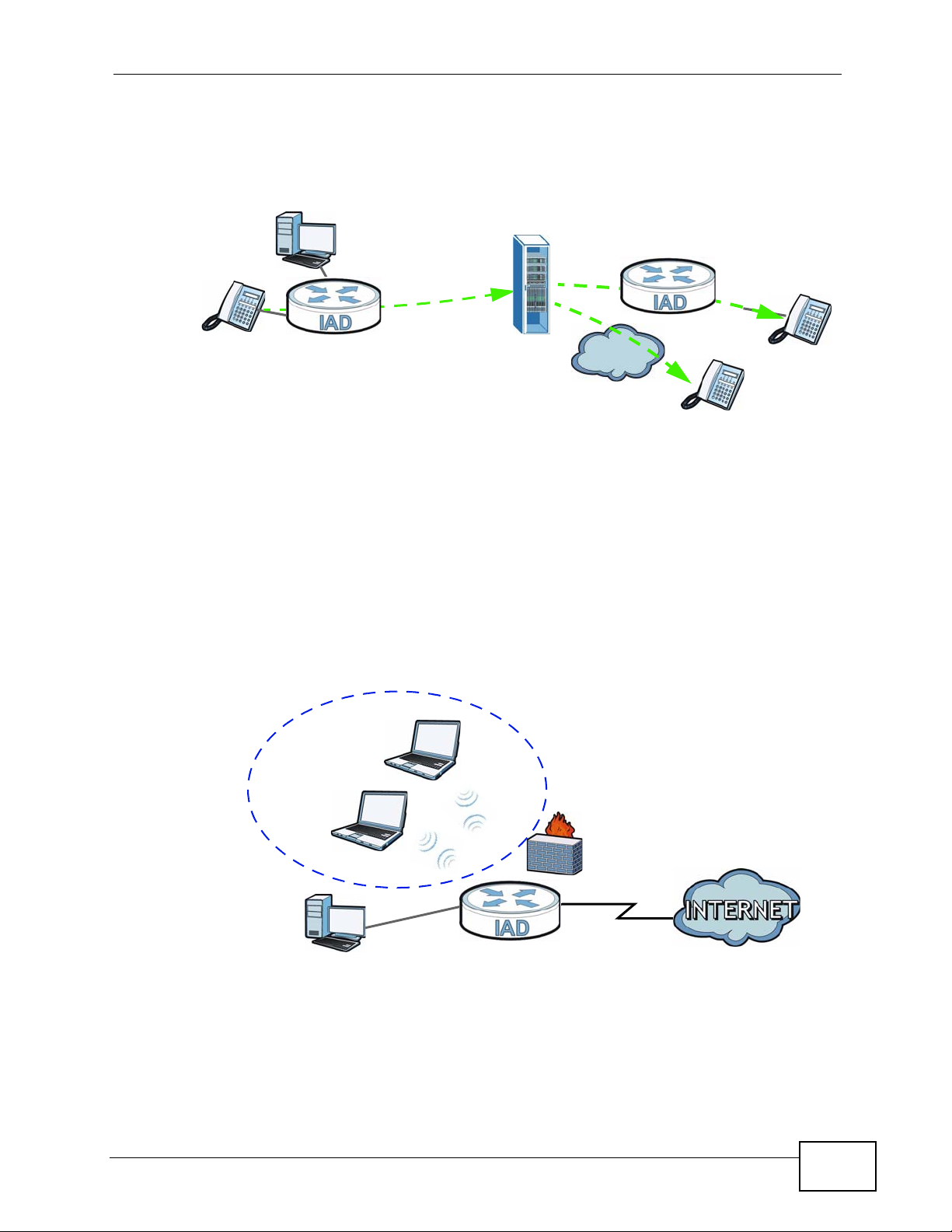
1.2.2 Internet Calls (VoIP)
You can register a SIP (Session Initiation Protocol) account and use the ZyXEL
Device to make and receive VoIP telephone calls: You can register a SIP (Session
22
P-2601HN(L)-F1 Series User’s Guide
Page 23
Chapter 1 Introducing the ZyXEL Device
PSTN
LAN
WLAN
WAN
Initiation Protocol) account and use the ZyXEL Device to make and receive VoIP
telephone calls:
Figure 2 ZyXEL Device’s VoIP Application
• Calls via a VoIP service provider - The ZyXEL Device sends your call to a VoIP
service provider’s SIP server which forwards your calls to either VoIP or PSTN
phones.
1.2.3 Wireless Connection
By default, the wireless LAN (WLAN) is enabled on the ZyXEL Device. IEEE
802.11b/g/n compliant clients can wirelessly connect to the ZyXEL Device to
access network resources. You can set up a wireless network with WP S (WiFi
Protected Setup) or manually add a client to your wireless network.
Figure 3 Wireless Connection Application
1.3 Ways to Manage the ZyXEL Device
Use any of the following methods to manage the ZyXEL Device.
P-2601HN(L)-F1 Series User’s Guide
23
Page 24
Chapter 1 Introducing the ZyXEL Device
• Web Configur ator. This is recommended for everyday management of the ZyXEL
Device using a (supported) web browser.
• Command Line Interface (administrator account only). Line commands are
mostly used for troubleshooting by service engineers.
• FTP for firmware upgrades and configuration backup/restore.
1.4 Good Habits for Managing the ZyXEL Device
Do the following things regularly to make the ZyXEL Device more secure and to
manage the ZyXEL Device more effectively.
• Change the password. Use a password that’s not easy to guess and that consists
of different types of characters, such as numbers and letters.
• Write down the password and put it in a safe place.
• Back up the configuration (and make sure you know how to restore it).
Restoring an earlier working configuration may be useful if the device becomes
unstable or even crashes. If you forget y our password, you will hav e to reset the
ZyXEL Device to its factory default settings . If yo u backed up an earlier
configuration file, you would not have to totally re-configure the ZyXEL Device.
You could simply restore your last configuration.
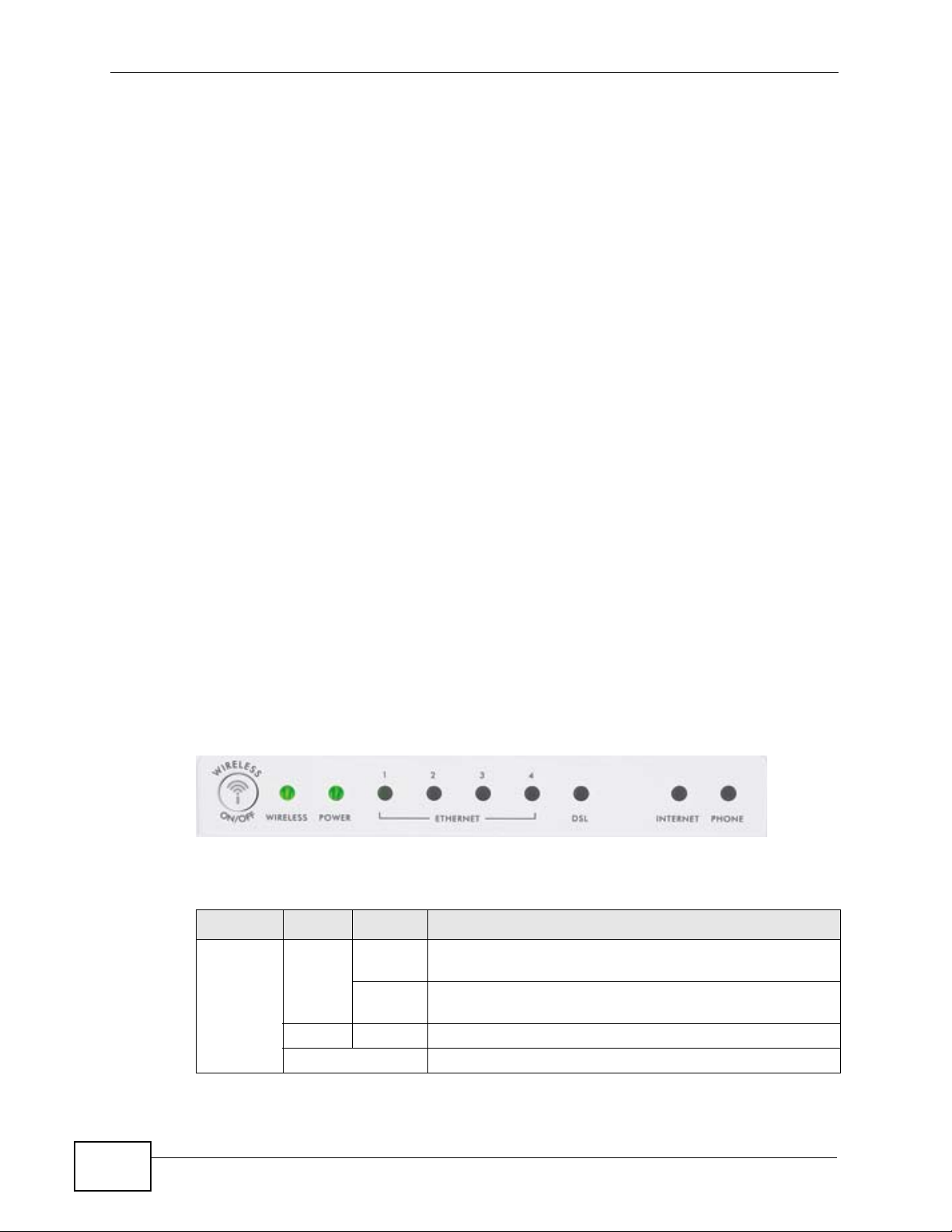
1.5 LEDs (Lights)
The following graphic displays the labels of the LEDs.
Figure 4 LEDs on the Top of the Device
None of the LEDs are on if the ZyXEL Device is not receiving power.
Table 1 LED Descriptions
LED COLOR STATUS DESCRIPTION
WIRELESS Green On The wireless network is activated and is operating in
Blinking The ZyXEL Device is communicating with other wireless
Orange Blinking The ZyXEL Device is setting up a WPS connection.
Off The wireless network is not activated.
IEEE 802.11b/g/n mode.
clients.
24
P-2601HN(L)-F1 Series User’s Guide
Page 25

Chapter 1 Introducing the ZyXEL Device
Table 1 LED Descriptions
LED COLOR STATUS DESCRIPTION
POWER Green On The ZyXEL Device is receiving power and ready for use.
Blinking The ZyXEL Device is performing Power On Self Test
(POST).
Red On The Z yXEL Device detected an error while self-testing, or
there is a device malfunction.
Off The ZyXEL Device is not receiving power.
ETHERNET
1-4
DSL Green On The DSL line is up.
INTERNET Green On The ZyXEL Device has an IP connection but no traffic.
Green On The ZyXEL Device has an Ethernet conne ction with a
device on the Local Area Network (LAN).
Blinking The ZyXEL Device is sending/receiving data to/from the
LAN.
Off The ZyXEL Device does no t hav e an Ethernet conn ection
with the LAN.
Blinking The ZyXEL Device is initializing the DSL line.
Off The DSL line is down.
Your device has a WAN IP address (either static or
assigned by a DHCP server), PPP negotiation was
successfully completed (if used) and the DSL connection
is up.
Blinking The ZyXEL Device is sending or receiving IP traffic.
Red On The ZyXEL Device attempted to make an IP connection
but failed. Possible causes are no response from a DHCP
server, no PPPoE response, PPPoE authentication failed.
Off The ZyXEL Device does not have an IP connection.
PHONE Green On A SIP account is registered for the phone port.
Blinking A telephone connected to the phone port has its receiver
off of the hook or there is an incoming call.
Orange On A SIP account is registered for the phone port and there
is a voice message in the corresponding SIP account.
Blinking A telephone connected to the phone port has its receiver
off of the hook and there is a voice message in the
corresponding SIP account.
Off The phone port does not have a SIP account registered.
Refer to the Quick Start Guide for information on hardware connections.
1.6 The RESET Button
If you forget your password or cannot access the web configurator, you will need
to use the RESET button at the back of the device to reload the factory-default
P-2601HN(L)-F1 Series User’s Guide
25
Page 26

Chapter 1 Introducing the ZyXEL Device
configuration file. This means that you will lose all configurations that you had
previously and the passwords will be reset to the defaults.
1 Make sure the POWER LED is on (not blinking).
2 To set the device back to the factory default settings, press the RESET button for
5 seconds or until the POWER LED begins to blink and then release it. When the
POWER LED begins to blink, the defaults have been restored and the device
restarts.
1.7 The WIRELESS ON/OFF Button
Use the WIRELESS ON/OFF button ( ) on the top of the device to turn the
wireless LAN off or on. You can also use it to activate WPS in ord er to q ui c kl y set
up a wireless network with strong security. Make sure the POWER LED is on (not
blinking) before using the WIRELESS ON/OFF button.
•Press the WIRELESS ON/OFF button for one to five (1 - 5) second/s and
release it. The WIRELESS LED should change from on to off or vice versa.
•Press the WIRELESS ON/OFF button for more than five seconds to turn on
WPS. See Section 6.4 on page 93 for more on using WPS to configure your
wireless clients.
26
P-2601HN(L)-F1 Series User’s Guide
Page 27

CHAPTER 2
Introducing the Web
Configurator
2.1 Overview
The web configurator is an HTML-based management interface that allows easy
device setup and management via Internet browser. Use Internet Explorer 6.0 and
later versions, Mozilla Firefox 3 and later versions, or Safari 2.0 and later versions.
The recommended screen resolution is 1024 by 768 pixels.
In order to use the web configurator you need to allow:
• Web browser pop -up windows from your device. W eb pop-up blocking is enabl ed
by default in Windows XP SP (Service Pack) 2.
• JavaScript (enabled by default).
• Java permissions (enabled by default).
See Appendix C on page 291 if you need to make sure these functions are allowed
in Internet Explorer.
2.1.1 Accessing the Web Configurator
1 Make sure your ZyXEL Device hardware is properly connected (refer to the Quick
Start Guide).
2 Launch your web browser.
3 Type "192.168.1.1" as the URL.
P-2601HN(L)-F1 Series User’s Guide
27
Page 28
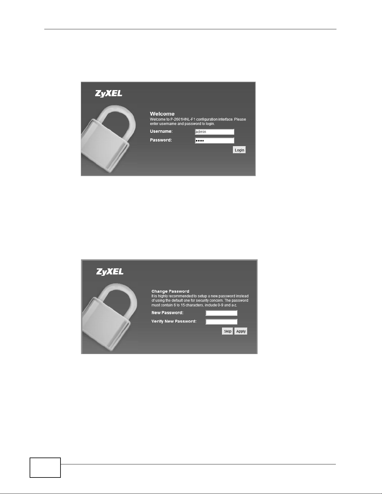
Chapter 2 Introducing the Web Configurator
4 A password screen displays. Type “admin” (default) as the username and “1234”
as the password, and click Login. If you have changed the pa ssword, enter your
password and click Login.
Figure 5 Password Screen
Note: For security reasons, the ZyXEL Device automatically logs you out if you d o not
use the web configurator for five minutes (default). If this happens, log in again.
5 The following screen displays if you have not yet changed your password. It is
strongly recommended you change the default password. Enter a new password,
retype it to confirm and click Apply; alternatively click Skip to proceed to the
main menu if you do not want to change the password now.
Figure 6 Change Password Screen
28
P-2601HN(L)-F1 Series User’s Guide
Page 29
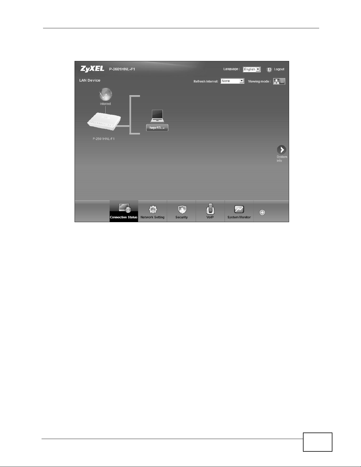
6 The Connection Status screen appears.
Figure 7 Connection Status
Chapter 2 Introducing the Web Configurator
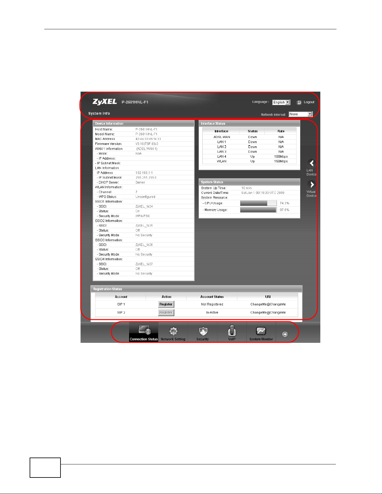
7 Click System Info to display the System Info screen, where you can view the
ZyXEL Device’s interface and system information.
P-2601HN(L)-F1 Series User’s Guide
29
Page 30
Chapter 2 Introducing the Web Configurator
B
C
A
2.2 The Web Configurator Layout
Click Connection Status > System Info to show the following screen.
Figure 8 Web Configurator Layout
As illustrated above, the main screen is divided into these parts:
• A - title bar
• B - main window
• C - navigation panel
30
P-2601HN(L)-F1 Series User’s Guide
Page 31

2.2.1 Title Bar
The title bar shows the following icon in the upper right co rner.
Click this icon to log out of the web configurator.
2.2.2 Main Window
The main window displays information and configuration fields. It is discussed in
the rest of this document.
After you click System Info on the Connection Status screen, the System Info
screen is displayed. See Chapter 4 on page 63 for more information about the
System Info screen.
If you click LAN Device on the System Info screen, the Connection Status
screen appears. See Chapter 4 on page 61 for more information about the
Connection Status screen.
Chapter 2 Introducing the Web Configurator
If you click Virtual Device on the System Info screen, a visual graphic appears,
showing the connection status of the ZyXEL Device’s ports. The connected ports
are in color and disconnected ports are gray.
2.2.3 Navigation Panel
Use the menu items on the navigation panel to open screens to configure ZyXEL
Device features. The following table describes each menu item.
Table 2 Navigation Panel Summary
LINK TAB FUNCTION
Connection
Status
Network Setting
Broadband Broadband Use this screen to configure Internet mode and
This screen shows the network status of the ZyXEL
Device and computers/devices connected to it.
encapsulation, IP address assignment, DNS servers
and other advanced properties.
P-2601HN(L)-F1 Series User’s Guide
31
Page 32

Chapter 2 Introducing the Web Configurator
Table 2 Navigation Panel Summary (continued)
LINK TAB FUNCTION
Wireless General Use this screen to turn the wireless connection on or
More AP Use this screen to configure multiple BSSs on the
WPS Use this screen to use WPS (Wi-Fi Protected Setup) to
WMM Use this screen to enable or disable Wi-Fi MultiMedia
Scheduling Use this screen to configure when the ZyXEL Device
Home
Networking
Static Route Static Route Use this screen to view and set up static routes on the
DNS Route DNS Route Use this screen to view and configure DNS routes.
QoS General Use this screen to enable QoS and decide allowable
NAT Port
Dynamic DNS Dynamic DNS Use this screen to allow a static hostname alias for a
Security
Firewall General Use this screen to activate/deactivate the firewall.
MAC Filter MAC Filter Use this screen to allow specific devices to access the
Certificates Local
VoIP
LAN Setup Use this screen to configure LAN TCP/IP settings, and
Static DHCP Use this screen to assign specific IP addresses to
UPnP Use this screen to enable the UPnP function.
Queue Setup Use this screen to configure QoS queue assignment.
Class Setup
Monitor
Forwarding
Sessions Use this screen to limit the number of NAT sessions a
Services Use this screen to set the default action to take on
Certificates
Trusted CA Use this screen to save CA certificates to the ZyXEL
off, specify the SSID(s) and configure the wireless
LAN settings and WLAN authentication/security
settings.
ZyXEL Device.
establish a wireless connection.
(WMM).
enables or disables the wireless LAN.
other advanced properties.
individual MAC addresses.
ZyXEL Device.
bandwidth using QoS.
Use this screen to set up classifiers to sort traffic into
different flows and assign priority and define actions
to be performed for a classified traffic flow.
Use this screen to view each queue’s statistics.
Use this screen to make your local servers visible to
the outside world.
single client can establish.
dynamic IP address.
network traffic going in specific directions.
ZyXEL Device.
Use this screen to generate and export self-signed
certificates or certification requests and import the
ZyXEL Device’s CA-signed certificates.
Device.
32
P-2601HN(L)-F1 Series User’s Guide
Page 33

Chapter 2 Introducing the Web Configurator
Table 2 Navigation Panel Summary (continued)
LINK TAB FUNCTION
SIP SIP Service
Provider
SIP Account Use this screen to set up information about your SIP
Common Use this screen to configure RFC3262 support and
Phone Phone Device Use this screen to set which phone ports use which
Region Use this screen to select your location.
Call Rule Call Rule Use this screen to configure speed dial for SIP phone
FXO FXO Use this screen to set up the PSTN line you use to
System Monitor
Log Phone Log Use this screen to view the ZyXEL Device’s phone
VoIP Call
History
Traffic Status WAN Use this screen to view the status of all network traffic
LAN Use this screen to view the status of all network traffic
NAT Use this screen to view the status of NAT sessions on
VoIP Status VoIP Status Use this screen to view the SIP, phone, and call status
Maintenance
Users
Account
Remote
MGMT
SNMP SNMP Use this screen to configure through which
System System Use this screen to configure the Zy XEL Device’s name,
Time Setting Time Setting Use this screen to change your ZyXEL Device’s time
Log Setting Log Setting Use this screen to select which logs and/or immediate
Firmware
Upgrade
Users Account Use this screen to configure the passwords your user
Remote MGMT Use this screen to enable specific traffic directions for
Firmware
Upgrade
Use this screen to configure your ZyXEL Device’s
Voice over IP settings.
account and configure audio settings such as volume
levels for the phones connected to the ZyXEL Device.
bind interfaces on the ZyXEL Device.
SIP accounts.
numbers that you call often.
make regular phone calls.
logs.
Use this screen to view the ZyXEL Device’s VoIP call
history.
going through the WAN port of the ZyXEL Device.
going through the LAN ports of the ZyXEL Device.
the ZyXEL Device.
of the ZyXEL Device.
accounts.
network services.
interface(s) and from which IP address(es) users can
access the SNMP agent on the ZyXEL Device.
domain name, management inactivity time-out.
and date.
alerts your device is to record.
Use this screen to upload firmware to your device.
P-2601HN(L)-F1 Series User’s Guide
33
Page 34

Chapter 2 Introducing the Web Configurator
Table 2 Navigation Panel Summary (continued)
LINK TAB FUNCTION
Backup/
Restore
Reboot Reboot Use this screen to reboot the ZyXEL Device without
Diagnostic Ping Use this screen to test the connections to other
Backup/
Restore
DSL Line Use this screen to identify problems with the DSL
2.2.4 Status Bar
Check the status bar when you click Apply or OK to verify that the configuration
has been updated.
Use this screen to backup and restore your device’s
configuration (settings) or reset the factory default
settings.
turning the power off.
devices.
connection.
34
P-2601HN(L)-F1 Series User’s Guide
Page 35

CHAPTER 3
Tutorials
3.1 Overview
This chapter contains the following tutorials:
• Setting Up Your DSL Connecti on
• How to Set up a Wireless Network
• Setting Up NAT Port Forwarding
• How to Make a VoIP Call
• Configuring the MAC Address Filter
• Configuring Static Route for Routing to Another Network
• Configuring QoS Queue and Class Setup
• Access the ZyXEL Device Using DDNS
3.2 Setting Up Your DSL Connection
This tutorial shows you how to set up your Internet connection using the web
configurator.
If you connect to the Internet through a DSL connection, use the information from
your Internet Service Provider (ISP) to configure the ZyXEL Device. Do the
following steps:
1 Connect the ZyXEL Device properly. Refer to the Quick Start Guide for details on
the ZyXEL Device’s hardware connection.
2 Check the back panel of your device where the Ethernet ports are located and
make sure the DSL/WAN switch is pointing up to DSL.
3 Connect one end of a DSL cable to the DSL port of your ZyXEL Device. The other
end should be connected to the DSL port in your house or a DSL router/modem
provided by your ISP.
P-2601HN(L)-F1 Series User’s Guide
35
Page 36

Chapter 3 Tutorials
4 Connect one end of Ethernet cable to an Ethernet port on the ZyXEL Device and
the other end to a computer that you will use to access the web configurator.
5 Connect the ZyXEL Device to a power source, turn it on and wait for the POWER
LED to become a steady green. Turn on the modem provided by your ISP as well
as the computer.
Account Configuration
1 Click Network Setting > Broadband to open the following screen. Click Add
new WAN Interface.
2 For this example, the interface type is ADSL and the connection has the following
information.
General
Name MyDSLConnection
Type ADSL
Mode Routing
WAN Service
Type
ATM PVC Configuration
VPI/VCI 36/48
Encapsulation
Mode
Service
Category
PPP Information
PPP User Name 1234@DSL-Ex.com
PPP Password ABCDEF!
PPPoE Service
Name
Authentication
Method
PPPoE
LLC/SNAP-Bridging
UBR without PCR
My DSL
Auto
36
P-2601HN(L)-F1 Series User’s Guide
Page 37

Chapter 3 Tutorials
Static IP
Address
Others PPPoE Passthrough: Disabled
192.168.1.32
NAT: Enabled
IGMP Multicast Proxy: Enabled
Apply as Default Gateway: Enable
DNS Server: Static DNS IP Address (Primary:
192.168.1.254 Secondary: 192.168.1.253)
Enter or select these values and click Apply.
This completes your DSL WAN connection setting.
P-2601HN(L)-F1 Series User’s Guide
37
Page 38

Chapter 3 Tutorials
3 You should see a summary of your new DSL connection setup in the Broadband
screen as follows.
Try to connect to a website, such as “www. zyxel.com” to see if you have correctly
set up your Internet connection. Be sure to contact your service provider for any
information you need to configur e the WAN screens.
3.3 How to Set up a Wireless Network
This section gives you examples of how to set up an access point and wireless
client for wireless communication using the following parameters. The wireless
clients can access the Internet through the ZyXEL Device wirelessly.
3.3.1 Example Parameters
SSID SSID_Example3
802.11 mode 802.11b/g
Channel auto
Security WPA-PSK
(Pre-Shared Key: ThisismyWPA-PSKpre-sharedkey)
An access point (AP) or wireless router is referred to as the “AP” and a comp ut er
with a wireless network card or USB adapter is referred to as the “wireless client”
here.
We use the [Model #] web screens and M-302 utility screens as an example. The
screens may vary slightly for different models.
3.3.2 Configuring the AP
Follow the steps below to configure the wireless settings on your AP.
38
P-2601HN(L)-F1 Series User’s Guide
Page 39

Chapter 3 Tutorials
1 Open the Network Setting > Wireless > General screen in the AP’s web
configurator.
Tutorial: Network > Wireless LAN > General
2 Make sure Enable Wireless LAN is selected.
3 Enter “SSID_Example3” as the SSID and select Auto in the Channel Selection
field to have the device search for an available channel.
4 Select 802.11b/g in the Mode Select field.
5 Select More Secure as your security level and set security mode to WPA-PSK
and enter “ThisismyWPA-PSKpre-sharedkey” in the Pre-Shared Key field. Click
Apply.
P-2601HN(L)-F1 Series User’s Guide
39
Page 40

Chapter 3 Tutorials
C
AP
6 Click Connection Status > System Info.Verify your wireless and wireless
security settings under Device Information and check if the WLAN connection is
up under Interface Status.
Tutorial: Network > Wireless LAN > Sec uritOpen the Status screen. Verify your wireless and w ireless security settings under Devi ce Information and check if the WLAN conn ec ti on is up under Interface Status
Tutorial: Status
This finishes the configuration of the AP.
3.3.3 Configuring the Wireless Client
This section describes how to connect the wireless client to a network.
3.3.3.1 Connecting to a Wireless LAN
The following sections show you how to join a wireless network using the ZyXEL
utility, as in the following diagram. The wireless client is labeled C and the access
point is labeled AP.
There are three ways to connect the client to an access point.
40
• Configure nothing and leave the wireless client to automatically scan for and
connect to any available network that has no wireless security configured.
• Manually connect to a network.
• Configure a profile to have the wireless client automatically connect to a specific
network or peer computer.
P-2601HN(L)-F1 Series User’s Guide
Page 41

Chapter 3 Tutorials
This example illustrates how to manually connect your wireless cli ent to an access
point (AP) which is configured for WPA-PSK security and connected to the
Internet. Before you connect to the access point, you must know its Service Set
IDentity (SSID) and WPA-PSK pre-shared key. In this example, the SSID is
“SSID_Example3” and the pre-shared key is “ThisismyWPA-PSKpre-sharedkey”.
After you install the ZyXEL utility and then insert the wireless client, follow the
steps below to connect to a network using the Site Survey screen.
1 Open the ZyXEL utility and click the Site Survey tab to open the screen shown
next.
Tutorial: Site Survey
2 The wireless client automatically searches for available wireless networks. Click
Scan if you want to search again. If no entry displays in the Available Network
List, that means there is no wireless network available with i n range. Make su re
the AP or peer computer is turned on or move the wireless client closer to the AP
or peer computer.
3 When you try to connect to an AP with security configur ed , a window will po p up
prompting you to specify the security settings. Enter the pre-shared k ey and leave
the encryption type at the default setting.
Use the Next button to move on to the next screen. You can use the Back button
at any time to return to the previous screen, or the Exit button to return to the
Site Survey screen.
Tutorial: Security Settings
P-2601HN(L)-F1 Series User’s Guide
41
Page 42

Chapter 3 Tutorials
4 The Confirm Save window appears. Check your settings and click Save to
continue.
Tutorial: Confirm Save
5 The ZyXEL utility returns to the Link Info screen while it connects to the wireless
network using your settings. When the wireless link is established, the ZyXEL
utility icon in the system tray turns green and the Link Info screen displays
details of the active connection. Check the network information in the Link Info
screen to verify that you have successfully connected to the selected network. If
the wireless client is not connected to a network, the fields in this screen remain
blank.
Tutorial: Link Info
6 Open your Internet browser and enter http://www.zyxel.com or the URL of any
other web site in the address bar. If you are able to access the web site, your
wireless connection is successfully configured.
If you cannot access the web site, try changing the encryption type in the
Security Settings screen, check the Troubleshooting section of this User's Guide
or contact your network administrator.
3.3.3.2 Creating and Using a Profile
A profile lets you easily connect to the same wireless network again later. You can
also configure different profiles for different networks, for example if you connect
a notebook computer to wireless networks at home and at work.
This example illustrates how to set up a profile and connect the wireless client to
an AP configured for WPA-PSK security. In this example, the SSID is
42
P-2601HN(L)-F1 Series User’s Guide
Page 43

Chapter 3 Tutorials
“SSID_Example3”, the profile name is “PN_Example3” and the pre-shared key is
“ThisismyWPA-PSKpre-sharedkey”. You have chosen the profile name
“PN_Example3”.
1 Open the ZyXEL utility and click the Profile tab to open the screen shown next.
Click Add to configure a new profile.
Tutorial: Profile
2 The Add New Profile screen appears. The wireless client automatically searches
for available wireless networks, and displa ys them in the Scan Info box. Click
Scan if you want to search again. Y ou can also configure your profile for a wireless
network that is not in the list.
Tutorial: Add New Profile
3 Give the profile a descriptive name (of up to 32 printable ASCII char acters). Select
Infrastructure and either manually enter or select the AP's SSID in the Scan
Info table and click Select.
4 Choose the same encryption method as the AP to which you want to connect (In
this example, WPA-PSK).
Tutorial: Profile Securit y
P-2601HN(L)-F1 Series User’s Guide
43
Page 44

Chapter 3 Tutorials
5 This screen varies depending on the encryption method you selected in the
previous screen. Enter the pre-shared key and leave the encryption type at the
default setting.
Tutorial: Profile Encryp tion
6 In the next screen, leave both boxes selected.
Tutorial: Wireless Protocol Settings.
7 Verify the profile s ettings in the read-only screen. Click Save to save and go to the
next screen.
Tutorial: Confirm Save
8 Click Activate Now to use the new profile immediately. Otherwise, click the
Activate Later button.
If you clicked Activate Later, you can select the profile from the list in the Profile
screen and click Connect to activate it.
44
P-2601HN(L)-F1 Series User’s Guide
Page 45

Chapter 3 Tutorials
D=192.168.1.34
WAN
LAN
port 666
A
Note: Only one profile can be activated and used at any given time.
Tutorial: Activate
9 When you activate the new profile, the ZyXEL utility returns to the Link Info
screen while it connects to the AP using your settings. When the wireless link is
established, the ZyXEL utility icon in the system tray turns gr een and the Link
Info screen displays details of the active connection.
10 Open your Internet browser, enter http://www.zyxel.com or the URL of any other
web site in the address bar and press ENTER. If you are able to access the web
site, your new profile is successfully configured.
If you cannot access the Internet go back to the Profile screen, select the profile
you are using and click Edit. Check the details you entered previously. Also, refer
to the Troubleshooting section of this User's Guide or contact your network
administrator if necessary.
3.4 Setting Up NAT Port Forwarding
In this tutorial, you manage the Doom server on a computer behind the ZyXEL
Device. In order for players on the Internet (like A in the figure below) to
communicate with the Doom server, you need to configure the port settings and IP
address on the ZyXEL Device. Traffic should be forwarded to the port 666 of the
Doom server computer which has an IP address of 192.168.1.34.
Tutorial: NAT Port Forwarding Setup
You may set up the port settings by configuring the port settings for the Doom
server computer (see Chapter 11 on page 150 for more information).
P-2601HN(L)-F1 Series User’s Guide
45
Page 46

Chapter 3 Tutorials
1 Click Network Setting > NAT > Port Forwarding. Click Add new rule.
2 Enter the following values:
Service Name Sele ct User Defined.
WAN Interface Select the WAN interface through which the Doom service is
Start/End Ports 666
Translation Start/End
Ports
Server IP Address Enter the IP address of the Doom server. This is 192.168.1.34
Protocol Select TCP/UDP. This should be the protocol supported by the
forwarded. This is the default interface for this example, which is
MyDSLConnection.
666
for this example.
Doom server.
46
3 Click Apply.
4 The port forwarding settings you configured should appear in the table. Make sure
the Status check box for this rule is selected. Click Apply to have the ZyXEL
Device start forwarding port 666 traffic to the computer with IP address
192.168.1.34.
Players on the Internet then can have access to your Doom server.
P-2601HN(L)-F1 Series User’s Guide
Page 47

3.5 How to Make a VoIP Call
You can register a SIP account with the SIP server and make voice calls over the
Internet to another VoIP device.
The following parameters are used in this example:
SIP Service Provider Name ServiceProvider1
SIP Account Number 12345678
Username ChangeMe
Password ThisIsMySIP
3.5.1 VoIP Calls With a Registered SIP Account
T o use a registered SIP account, you should configure the SIP service provider and
applied for a SIP account.
Chapter 3 Tutorials
3.5.1.1 SIP Service Provider Configuration
Follow the steps below to configure your SIP service provider.
1 Make sure your ZyXEL Device is connected to the Internet.
2 Open the web configurator.
3 Click VoIP > SIP to open the SIP Service Provider screen. Select Add New
from the Service Provider Selection drop-down list box.
4 Select the Enable check box of SIP Service Provider and enter the SIP Service
Provider Name.
P-2601HN(L)-F1 Series User’s Guide
47
Page 48

Chapter 3 Tutorials
5 Go to the SIP Account screen, click the Edit icon of SIP 3.
6 Select the Active SIP Account check box, then enter the SIP Account Number,
Username, and Password. Leave other settings as default.
7 Click Apply to save your settings.
3.5.1.2 SIP Account Registration
Follow the steps below to register and activate your SIP account.
1 Click Connection Status > System Info to check if your SIP account has been
registered successfully. If the status is Not Registered, check your Internet
connection and click Register to register your SIP account.
Tutorial: Registration Status
48
P-2601HN(L)-F1 Series User’s Guide
Page 49

3.5.1.3 Analog Phone Configuration
1 Click VoIP > Phone to open the Phone Device screen. Click the Edit icon next
to Analog Phone 1 to configure the first phone port.
2 Select SIP 3 from the SIP Account in the SIP Account to Make Outgoing Call
section to have the phone (connected to the first phone port) use the registered
SIP 3 account to make outgoing calls.
3 Select the SIP 3 check box in the SIP Account(s) to Receive Incoming Call
section to have the phone (connected to the first phone port) receive phone calls
for the SIP 3 account.
4 Click Apply to save your changes.
Tutorial: VoIP > Phone
Chapter 3 Tutorials
3.5.1.4 Making a VoIP Call
1 Make sure you connect a telephone to th e first phone port on the ZyXEL Device.
2 Make sure the ZyXEL Device is on and connected to the Internet.
3 Pick up the phone receiver.
4 Dial the VoIP phone number you want to call.
P-2601HN(L)-F1 Series User’s Guide
49
Page 50

Chapter 3 Tutorials
Thomas
Josephine
3.6 Configuring the MAC Address Filter
Thomas noticed that his daughter Josephine spends too m uch time surfing the
web and downloading media files. He decided to prevent Josephine from accessing
the Internet so that she can concentrate on preparing for her final exams.
Josephine’s computer connects wirelessly to the Internet through the ZyXEL
Device. Thomas decides to use the Security > MAC Filter screen to grant
wireless network access to his computer but not to Josephine’s computer.
1 Click Security > MAC Filter to open the MAC Filter screen. Select the Enable
check box to activate MAC filter function.
2 Find the MAC address of Thomas’ computer in this screen. Select Allow. Click
Apply.
Thomas can also grant access to the computers of other members of his family
and friends. However, Josephine and others not listed in this screen will no longer
be able to access the Internet through the ZyXEL Device.
50
P-2601HN(L)-F1 Series User’s Guide
Page 51

Chapter 3 Tutorials
N2
B
N1
A
R
3.7 Configuring Static Route for Routing to Another Network
In order to extend your Intranet and control traffic flowing directions, you may
connect a router to the ZyXEL Device’s LAN. The router may be used to separate
two department networks. This tutorial shows how to configure a static routing
rule for two network routings.
In the following figure, router R is connected to the ZyXEL Device’s LAN. R
connects to two networks, N1 (192.168.1.x/24) and N2 (192.168.10.x/24). If
you want to send traffic from computer A (in N1 network) to com puter B (in N2
network), the traffic is sent to the ZyXEL Device’s WAN default gateway by
default. In this case, B will never receive the traffic.
You need to specify a static routing rule on the ZyXEL Device to specify R as the
router in charge of forwarding traffic to N2. In this case, the ZyXEL Device routes
P-2601HN(L)-F1 Series User’s Guide
51
Page 52

Chapter 3 Tutorials
N2
B
N1
A
R
traffic from A to R and then R routes the traffic to B.Th is tu torial uses the
following example IP settings:
Table 3 IP Settings in this Tutorial
DEVICE / COMPUTER IP ADDRESS
The ZyXEL Device’s WAN 172.16.1.1
The ZyXEL Device’s LAN 192.168.1.1
A 192.168.1.34
R’s N1 192.168.1.253
R’s N2 192.168.10.2
B 192.168.10.33
To configure a static route to route traffic from N1 to N2:
1 Click Network Setting > Routing. Click Add New Static Route.
2 Configure the Static Route Setup screen using the following settings:
• Select Active.
• Specify a descriptive name for this routing rule.
•Type 192.168.10.0 and subnet mask 255.255.255.0 for the destination, N2.
52
P-2601HN(L)-F1 Series User’s Guide
Page 53

Chapter 3 Tutorials
•Type 192.168.1.253 (R’s N1 address) in the Gateway IP Address field.
Click Apply. The Routing screen should display the route you just added.
Now B should be able to receive traffic from A. You may need to additionally
configure B’s firewall settings to allow specific traffic to pass through.
3.8 Configuring QoS Queue and Class Setup
This section contains tutorials on how you can configure the QoS screen.
Note: V oice traffic will not be affected by the user-defined QoS settings on the ZyXEL
Device. It always gets the highest priority.
Let’s say you are a team leader of a small sales branch office. You want to
prioritize e-mail traffic because your task includes sending urgent updates to
clients at least twice every hour. You also upload data files (such as logs and email archives) to the FTP server throughout the day. Your colleagues use the
Internet for research, as well as chat applications for communicating with other
branch offices.
In the following figure, your Internet connection has an upstream transmission
bandwidth of 10,000 kbps. For this exampl e, y ou want to configure QoS so that email traffic gets the highest priority with at least 5,000 kbps. You can do the
following:
• Configure a queue to assign the highest priority queue (7) to e-mail traffic from
the LAN interface, so that e-mail traffic would not get delayed when there is
network congestion.
• Note the IP address (192.168.1.23 for example) and/or MAC address
(AA:FF:AA:FF:AA:FF for example) of your computer and map it to queue 7.
P-2601HN(L)-F1 Series User’s Guide
53
Page 54

Chapter 3 Tutorials
10,000 kbps
DSL
E-mail: Queue 7
Your computer
IP=192.168.1.23
A colleague’s computer
Other traffic: Automatic classifier
and/or
MAC=AA:FF:AA:FF:AA:FF
Note: QoS is applied to traffic flowing out of the ZyXEL Device.
Traffic that does not match this class is assigned a priority queue based on the
internal QoS mapping table on the ZyXEL Device.
1 Click Network Setting > QoS > General and check Active. Set your WAN
Managed Upstream Bandwidth to 10,000 kbps (or leave this blank to have the
ZyXEL Device automatically determine this figure). Click Apply to save your
settings.
Tutorial: Advanced > QoS
2 Go to Network Setting > QoS > Queue Setup. Click Add new Queue to create
54
a new queue. In the screen that opens, check Active and enter or select the
following values, then click Apply.
• Name: Email
• Priority: 7 (High)
• Weight: 15
P-2601HN(L)-F1 Series User’s Guide
Page 55

Chapter 3 Tutorials
• Rate Limit: 5,000 (kbps)
Tutorial: Advanced > QoS > Queue Setup
3 Go to Network Setting > QoS > Class Setup. Click Add new Classifier to
create a new class. Check Active and follow the settings as shown in the screen
below. Then click Apply.
Tutorial: Advanced > QoS > Class Setup
Class Name Give a class name to this traffic, such as Email in this
example.
To Queue Link this to a queue created in the QoS > Queue
Setup screen, which is the Email queue created in
this example.
P-2601HN(L)-F1 Series User’s Guide
55
Page 56

Chapter 3 Tutorials
w.x.y.z
a.b.c.d
http://zyxelrouter.dyndns.org
A
From Interface This is the interface from which the traffic will be
Ether Type Select IP to identify the traffic source by its IP
MAC Address Type the MAC address of your computer -
IP Address Type the IP address of your computer -
This maps e-mail traffic to queue 7 created in the previous screen (see the IP
Protocol field). This also maps your computer’s IP address and MAC address to
queue 7 (see the Source fields).
4 Verify that the queue setup works by checking Network Setting > QoS >
Monitor. This shows the bandwidth allotted to e-mail traffic compared to other
network traffic.
Tutorial: Advanced > QoS > Monitor
coming from. Select Lan.
address or MAC address.
AA:FF:AA:FF:AA:FF. Type the MAC Mask if you
know it.
192.168.1.23. Type the IP Subnet Mask if you
know it.
3.9 Access the ZyXEL Device Using DDNS
If you connect your ZyXEL Devi ce to the Internet and it uses a dynamic WAN IP
address, it is inconvenient for you to manage the device from the Internet. The
ZyXEL Device’s WAN IP address changes dynamically. Dynamic DNS (DDNS)
allows you to access the ZyXEL Device using a domain name.
To use this feature, you have to apply for DDNS service at www.dyndns.org.
56
P-2601HN(L)-F1 Series User’s Guide
Page 57

Chapter 3 Tutorials
This tutorial shows you how to:
• Registering a DDNS Account on www.dyndns.org
• Configuring DDNS on Your ZyXEL Device
• Testing the DDNS Setting
Note: If you have a private WAN IP address, then you cannot use DDNS.
3.9.1 Registering a DDNS Account on www.dyndns.org
1 Open a browser and type http://www.dyndns.org.
2 Apply for a user account. This tutorial uses UserName1 and 12345 as the
username and password.
3 Log into www.dyndns.org using your account.
4 Add a new DDNS host name. This tutorial uses the following settings as an
example.
• Hostname: zyxelrouter.dyndns.org
•Service Type: Host with IP address
• IP Address: Enter the WAN IP address that your ZyXEL Devi ce is currently using.
You can find the IP address on the ZyXEL Device’s web configurator Status
page.
Then you will need to configure the same account and host name on the ZyXEL
Device later.
3.9.2 Configuring DDNS on Your ZyXEL Device
Configure the following settings in the Network Setting > DNS screen.
• Select Active Dynamic DNS.
• Select Dynamic DNS for the DDNS type.
•Type zyxelrouter.dyndns.org in the Host Name field.
P-2601HN(L)-F1 Series User’s Guide
57
Page 58

Chapter 3 Tutorials
• Enter the user name (UserName1) and password (12345).
Click Apply.
3.9.3 Testing the DDNS Setting
Now you should be able to access the ZyXEL Device from the Internet. To test
this:
1 Open a web browser on the computer (using the IP address a.b.c.d) that is
connected to the Internet.
2 Type http://zyxelrouter.dyndns.org and press [Enter].
3 The ZyXEL Device’s login page should appear. You can then log into the ZyXEL
Device and manage it.
58
P-2601HN(L)-F1 Series User’s Guide
Page 59

PART II
Technical Reference
59
Page 60

60
Page 61

CHAPTER 4
Connection Status and System
Info Screens
4.1 Overview
After you log into the web configurator, the Connection Status screen appears.
This shows the network connection status of the ZyXEL Device and clients
connected to it.
Use the System Info screen to look at the current status of the device, system
resources, interfaces (LAN, WAN and WLAN), and SIP accounts. You can also
register and unregister SIP accounts.
4.2 The Connection Status Screen
Use this screen to view the network connection status of the device and its clients.
A warning message appears if there is a connection problem.
P-2601HN(L)-F1 Series User’s Guide
61
Page 62

Chapter 4 Connection Status and System Info Screens
If you prefer to view the status in a list, click List View in the Viewing mode
selection box. You can configure how often you want
this screen in Refresh Interval.
Figure 9 Connection Status: Icon View
the ZyXEL Device to update
Figure 10 Connection Status: List View
In Icon View, if you want to view informatio n about a client, click the client’s
name and Info. Click the IP address if you want to change it. If you want to
change the name or icon of the client, click Change name/icon.
In List View, you can also view the client’s information.
62
P-2601HN(L)-F1 Series User’s Guide
Page 63

Chapter 4 Connection Status and System Info Screens
4.3 The System Info Screen
Click Connection Status > System Info to open this screen.
Figure 11 System Info Screen
Each field is described in the following table.
Table 4 System Info Screen
LABEL DESCRIPTION
Language Select the web configurator language from the drop-down list box.
Refresh Interval Select how often you want th e Z yXEL Device to update this screen from
the drop-down list box.
Device Information
Host Name This field displays the ZyXEL Device system name. It is used for
identification. You can change this in the Maintenance > System
screen’s Host Name field.
Model Name This is the model name of your device.
P-2601HN(L)-F1 Series User’s Guide
63
Page 64

Chapter 4 Connection Status and System Info Screens
LABEL DESCRIPTION
MAC
Address
Firmware
Version
WAN Information
Mode This is the method of encapsulation used by your ISP.
IP Address This field displays the current IP address of the ZyXEL Device in the
IP Subnet
Mask
LAN Information
IP Address This field displays the current IP address of the ZyXEL Device in the
IP Subnet
Mask
DHCP Server This field displays what DHCP services the ZyXEL Device is providing to
This is the MAC (Media Access Control) or Ethernet address unique to
your ZyXEL Device.
This field displays the current version of the firmware inside the device.
It also shows the date the firmware version was created. Go to the
Maintenance > Firmware Upgrade screen to change it.
WAN.
This field displays the current subnet mask in the WAN.
LAN.
This field displays the current subnet mask in the LAN.
the LAN. Choices are:
Server - The ZyXEL Device is a DHCP server in the LAN. It assigns IP
addresses to other computers in the LAN.
Relay - The ZyXEL Device acts as a surrogate DHCP server and relays
DHCP requests and responses between the remote server and the
clients.
None - The ZyXEL Device is not providing any DHCP services to the
LAN.
WLAN Information
Channel This is the channel number used by the ZyXEL Device now.
WPS Status Configured displays when a wireless client has connected to the ZyXEL
Device or WPS is enabled and wireless or wireless security settings have
been configured. Unconfigured displays if WPS is disabled or wireless
security settings have not been configured.
SSID (1~4)
Information
SSID This is the descriptive name used to identify the ZyXEL Device in the
wireless LAN.
Status This shows whether or not the SSID is enabled (on).
Security
Mode
Interface Status
Interface This column displays each interface the ZyXEL Device has.
This displays the type of security the ZyXEL Device is using in the
wireless LAN.
64
P-2601HN(L)-F1 Series User’s Guide
Page 65

Chapter 4 Connection Status and System Info Screens
LABEL DESCRIPTION
Status This field indicates whether or not the ZyXEL Device is using the
interface.
For the DSL interface, this field displays Down (line is down), Up (line
is up or connected) if you're using Ethernet encapsulation and Down
(line is down), Up (line is up or connected), Idle (line (ppp) idle), Dial
(starting to trigger a call) and Drop (dropping a call) if you're using
PPPoE encapsulation.
For the WAN interface, this field displays Up when the ZyXEL Device is
using the interface and Down when the ZyXEL Device is not using the
interface.
For the LAN interface, this field displays Up when the ZyXEL Device is
using the interface and Down when the ZyXEL Device is not using the
interface.
For the WLAN interface, it displays Up when WLAN is enabled or Down
when WLAN is disabled.
Rate For the LAN interface, this displays the port speed.
For the WAN interface, this displays the port speed.
For the DSL interface, it displays the downstream and upstream
transmission rate.
For the WLAN interface, it displays the maximum transmission rate
when WLAN is enabled or N/A when WLAN is disabled.
System Status
System Up
Time
Current
Date/Time
System Resource
CPU Usage This field displays what percentage of the ZyXEL Device’s processing
Memory
Usage
Registration St atus
Account This column displays each SIP account in the ZyXEL Device.
This field displays how long the ZyXEL Device has been running since it
last started up. The ZyXEL Device starts up when you plug it in, when
you restart it (Maintenance > Reboot), or when you reset it (see
Chapter 1 on page 25).
This field displays the current date and time in the ZyXEL Device. You
can change this in Maintenance > Time Setting.
ability is currently used. When this percentage is close to 100%, the
ZyXEL Device is running at full load, and the throughput is not going to
improve anymore. If you want some applications to have more
throughput, you should turn off other applications.
This field displays what percentage of the ZyXEL Device’s memory is
currently used. Usually, this percentage should not increase much. If
memory usage does get close to 100%, the ZyXEL Device is probably
becoming unstable, and you should restart the device. See Chapter 26
on page 231, or turn off the device (unplug the power) for a few
seconds.
P-2601HN(L)-F1 Series User’s Guide
65
Page 66

Chapter 4 Connection Status and System Info Screens
LABEL DESCRIPTION
Action This field displa ys the current registration status of the SIP account. Y ou
have to register SIP accounts with a SIP server to use VoIP.
If the SIP account is already registered with the SIP server,
• Click Unregister to delete the SIP account’s registration in the SIP
server. This does not cancel your SIP account, but it deletes the
mapping between your SIP identity and your IP address or domain
name.
• The second field displays Registered.
If the SIP account is not registered with the SIP server,
• Click Register to have the Z yXEL Device attempt to register the SIP
account with the SIP server.
• The second field displays the reason the account is not registered.
Inactive - The SIP account is not active. You can activate it in VoIP >
SIP > SIP Settings.
Register Fail - The last time the ZyXEL Device tried to register the SIP
account with the SIP server, the attempt failed. The ZyXEL Device
automatically tries to register the SIP account when you turn on the
ZyXEL Device or when you activate it.
Account
Status
URI This field displays the account number and service domain of the SIP
This shows Active when the SIP account has been registered and ready
for use or In-Active when the SIP account is not yet registered.
account. You can change these in VoIP > SIP > SIP Settings.
66
P-2601HN(L)-F1 Series User’s Guide
Page 67

CHAPTER 5
WAN
LAN
Broadband
5.1 Overview
This chapter describes how to configure WAN settings from the Broadband
screen. Use this screen to configure your ZyXEL Device for Internet access.
A WAN (Wide Area Network) connection is an outside connection to another
network or the Internet. It connects your private networks (such as a LAN (Local
Area Network) and other networks, so that a computer in one location can
communicate with computers in other locations.
Figure 12 LAN and WAN
5.1.1 What You Need to Know
Encapsulation Method
Encapsulation is used to include data from an upper layer protocol into a lower
layer protocol. To set up a WAN connection to the Internet, you need to use the
same encapsulation method used by your ISP (Internet Service Provider). If your
ISP offers a dial-up Internet connection using PPPoE (PPP over Ethernet) or PPPoA,
they should also provide a username and password (and service name) for user
authentication.
P-2601HN(L)-F1 Series User’s Guide
67
Page 68

Chapter 5 Broadband
WAN IP Address
The WAN IP address is an IP address for the ZyXEL Device, which makes it
accessible from an outside network. It is used by the ZyXEL Device to
communicate with other devices in other networks. It can be static (fixed) or
dynamically assigned by the ISP each time the ZyXEL Device tries to access the
Internet.
If your ISP assigns you a static WAN IP address, they should also assign you the
subnet mask and DNS server IP address(es) (and a gateway IP add ress if you use
the Ethernet encapsulation method).
Multicast
Traditionally, IP packets are transmitted in one of either two ways - Unicast (1
sender - 1 recipient) or Broadcast (1 sender - everybody on the network).
Multicast delivers IP packets to a group of hosts on the network - not everybody
and not just one.
IGMP
IGMP (Internet Group Multicast Protocol) is a network-layer protocol used to
establish membership in a Multicast group - it is not used to carry user data.
There are three versions of IGMP. IGMP version 2 and 3 are improvements over
version 1, but IGMP version 1 is still in wide use.
Finding Out More
See Section 5.3 on page 76 for technical background information on WAN.
5.1.2 Before You Begin
You need to know your Internet access settings such as encapsulation and W AN IP
address. Get this information from your ISP.
68
P-2601HN(L)-F1 Series User’s Guide
Page 69

5.2 The Broadband Screen
Use this screen to change your ZyXEL Device ’s Internet access settings. Click
Network Setting> Broadband from the menu. The summary table shows you
the configured WAN services (connections) on the ZyXEL D evice.
Figure 13 Network Setting > Broadband
The following table describes the labels in this screen.
Table 5 Network Setting > Broadband
LABEL DESCRIPTION
Add new WAN
interface
# This is the index number of the entry.
Status This is the status of the connection.
Name This is the service name of the connection.
Type This shows the type of interface used by this connection.
Mode This shows whether the connection is in routing mode or bridge mode.
Encapsulation This is the method of encapsulation used by this connection.
VPI/VCI This is the Virtual Path Identifier (VPI).
VCI This is the Virtual Channel Identifier (VCI).
Vlan8021p This indicates the 802.1P priority level assigned to traffic sent through
VlanMuxId This indicates the VLAN ID number assigned to traffic sent through
ATM QoS This is the type of ATM QoS of the connection.
IGMP Proxy This shows whether the ZyXEL Device act as an IGMP proxy on this
NAT This shows whether NAT is activated or not for this connection.
Default Gateway This shows whether the ZyXEL Device use the WAN interface of this
Modify Click the Edit icon to configure the connection.
Click this button to create a new connection.
this connection. This displays N/A when there is no priority level
assigned.
this connection. This displays N/A when there is no VLAN ID number
assigned.
connection.
connection as the system default gateway.
Chapter 5 Broadband
Click the Delete icon to remove the connection.
P-2601HN(L)-F1 Series User’s Guide
69
Page 70

Chapter 5 Broadband
5.2.1 Add/Edit Broadband
Click Add new WAN interface in the Broadband screen or the Edit icon next to
an existing WAN interface to configure a WAN connection. The screen differs
according to the mode and encapsulation you choose.
This screen displays when you select the Routing mode and PPPoE
encapsulation. The fields in the screen may differ depending on the type of
encapsulation you use.
Figure 14 Broadband: Add/Edit: Routing Mode
70
P-2601HN(L)-F1 Series User’s Guide
Page 71

Chapter 5 Broadband
The following table describes the labels in this screen.
Table 6 Broadband: Add/Edit: Routing Mode
LABEL DESCRIPTION
General
Name Enter a service name of the connection.
Type The interface type used by the ZyXEL Device is ADSL. The ZyXEL
Device uses the ADSL technology for data transmission over the DSL
port.
Mode Select Routing (default) from the drop-down list box if your ISP give
you one IP address only and you want multiple computers to share an
Internet account.
WAN Service
Type
ATM PVC
Configuration
VPI The valid range for the VPI is 0 to 255. Enter the VPI assigned to you.
VCI The valid range for the VCI is 32 to 65535 (0 to 31 is reserved for local
DSL Link Type If your WAN Service Type is PPPoE or IPoE, the DSL link type is set
Select the method of encapsulation used by your ISP from the dropdown list box. This option is available only when you select Routing in
the Mode field.
The choices are PPPoE, PPPoA, and IPoE.
VPI (Virtual Path Identifier) and VCI (Virtual Channel Identifier) define
a virtual circuit.
management of ATM traffic). Enter the VCI assigned to you.
to EoA (Ethernet over ATM) to have an Ethernet header in the packet,
so that you can have multiple services/connections over one PVC. You
can set each connection to have its own MAC address or all connections
share one MAC address but use different VLAN IDs for different
services. EoA supports IPoE, PPPoE and RFC1483/2684 bridging
encapsulation methods.
Encapsulation
Mode
If your WAN Service Type is PPPoA, the DSL link type is set to
PPPoA (PPP over ATM) to allow just one PPPoA connection over a PVC.
Select the method of multiplexing used by your ISP from the dropdown list box. Choices are:
• LLC/SNAP-BRIDGING: In LCC encapsulation, bridged PDUs are
encapsulated by identifying the type of the bridged media in the
SNAP header.
• VC/MUX: In VC multiplexing, each protocol is carried on a single
ATM virtual circuit (VC). To transport multiple protocols, the ZyXEL
Device needs separate VCs. There is a binding between a VC and
the type of the network protocol carried on the VC. This reduces
payload overhead since there is no need to carry protocol
information in each Protocol Data Unit (PDU) payload.
P-2601HN(L)-F1 Series User’s Guide
71
Page 72

Chapter 5 Broadband
Table 6 Broadband: Add/Edit: Routing Mode (continued)
LABEL DESCRIPTION
Service
Category
Peak Cell
Rate
Sustainable
Cell Rate
Select UBR Without PCR for applications that are non-time sensitive,
such as e-mail.
Select CBR (Constant Bit Rate) to specify fixed (always-on) bandwidth
for voice or data traffic.
Select Non Realtime VBR (non real-time Variable Bit Rate) for
connections that do not require closely controlled delay and delay
variation.
Select Realtime VBR (real-time V ariable Bit Rate) for applications with
bursty connections that require closely controlled delay and delay
variation.
Divide the DSL line rate (bps) by 424 (the size of an ATM cell) to find
the Peak Cell Rate (PCR). This is the maximum rate at wh ich the sender
can send cells. Type the PCR here.
This field is not available when you select UBR Without PCR.
The Sustain Cell Rate (SCR) sets the average cell rate (long-term) that
can be transmitted. Type the SCR, which must be less than the PCR.
Note that system default is 0 cells/sec.
This field is available only when you select Non Realtime VBR or
Realtime VBR.
Maximum
Burst Size
PPP Information This section is available only when you select Routing in the Mode
PPP User Name Enter the user name exactly as your ISP assigned. If assigned a name
PPP Password Enter the password associated with the user name above.
PPPoE Service
Name
Authentication
Mode
Maximum Burst Size (MBS) refers to the maximum number of cells that
can be sent at the peak rate. Type the MBS, which is less than 65535.
This field is available only when you select Non Realtime VBR or
Realtime VBR.
field and PPPoE or PPPoA in the WAN Service Type field.
in the form user@domain where domain identifies a service name, then
enter both components exactly as given.
Type the name of your PPPoE service here. This field is available only
when you select PPPoE in the WAN Service Type field.
The ZyXEL Device supports PAP (P assword Authentication Protocol) and
CHAP (Challenge Handshake Authentication Protocol). CHAP is more
secure than PAP; however, PAP is readily available on more platforms.
Use the drop-down list box to select an authentication protocol for
outgoing calls. Options are:
AUTO: Your ZyXEL Device accepts either CHAP or PAP when requested
by this remote node.
72
PAP: Your ZyXEL Device accepts PAP only.
CHAP: Your ZyXEL Device accepts CHAP only.
MS-CHAP: Your ZyXEL Device accepts MSCHAP only. MS-CHAP is the
Microsoft version of the CHAP.
P-2601HN(L)-F1 Series User’s Guide
Page 73

Chapter 5 Broadband
Table 6 Broadband: Add/Edit: Routing Mode (continued)
LABEL DESCRIPTION
Use Static IP
Address
IP Address Enter the static IP address provided by your ISP.
PPPoE
Passthrough
IP Address This section is available only when you select Routing in the Mode
Obtain an IP
Address
Automatically
Enable DHCP
Option 60
Vendor Class
Identifier
Static IP
Address
IP Address Enter the static IP address provided by your ISP.
Subnet Mask Enter the subnet mask provided by your ISP.
Gateway IP
Address
Routing Feature
NAT Enable Select this option to activate NAT on this connection.
IGMP Proxy
Enable
A static IP address is a fixed IP that your ISP gives you. A dynamic IP
address is not fixed; the ISP assigns you a different one each time you
connect to the Internet. Select this if you want to get a dynamic IP
address from the ISP.
In addition to the ZyXEL Device’s built-in PPPoE client, you can enable
PPPoE pass through to allow up to ten hosts on the LAN to use PPPoE
client software on their computers to connect to the ISP via the ZyXEL
Device. Each host can have a separate account and a public WAN IP
address.
PPPoE pass through is an alternative to NAT for application where NAT
is not appropriate.
Disable PPPoE pass through if you do not need to allow hosts on the
LAN to use PPPoE client software on their computers to connect to the
ISP.
This field is available only when you select PPPoE in the WAN Service
Type field.
field and IPoE in the WAN Service Type field.
A static IP address is a fixed IP that your ISP gives you. A dynamic IP
address is not fixed; the ISP assigns you a different one each time you
connect to the Internet. Select this if you have a dynamic IP address.
Select this to identify the vendor and functionality of the ZyXEL Device
in DHCP requests that the ZyXEL Device sends to a DHCP server when
getting a WAN IP address.
Enter the Vendor Class Identifier (Option 60), such as the type of the
hardware or firmware.
Select this option If the ISP assigned a fixed IP address.
Enter the gateway IP address provided by your ISP.
Internet Group Multicast Protocol (IGMP) is a network-layer protocol
used to establish membership in a Multicast group - it is not used to
carry user data.
Select this option to have the ZyXEL Device act as an IGMP proxy on
this connection. This allows the ZyXEL Device to get subscribing
information and maintain a joined member list for each multicast
group. It can reduce multicast traffic significantly.
Apply as Default
Gateway
DNS Server The section is not available when you select Bridge in the WAN
Select this option to have the ZyXEL Device use the WAN interface of
this connection as the system default gateway.
Service Type field.
P-2601HN(L)-F1 Series User’s Guide
73
Page 74

Chapter 5 Broadband
Table 6 Broadband: Add/Edit: Routing Mode (continued)
LABEL DESCRIPTION
Obtain DNS info
Automatically
Use the
following Static
DNS IP Address
Primary DNS
Server
Secondary
DNS Server
Apply Click Apply to save your changes.
Back Click Back to return to the previous screen.
5.2.1.1 Bridge
This screen displays when you select the Bridge mode.
Figure 15 Broadband: Add/Edit: Bridge Mode
Select this to have the ZyXEL Device get the DNS server addresses
from the ISP automatically.
Select this to have the ZyXEL Device use the DNS server addresses you
configure manually.
Enter the first DNS server address assigned by the ISP.
Enter the second DNS server address assigned by the ISP.
74
The following table describes the labels in this screen.
Table 7 Broadband: Add/Edit: Bridge Mode
LABEL DESCRIPTION
General
Name Specify a descriptive name of up to 15 alphanumeric characters for this
connection.
Type The interface type used by the ZyXEL Device is ADSL. The ZyXEL
Device uses the ADSL technology for data transmission over the DSL
port.
P-2601HN(L)-F1 Series User’s Guide
Page 75

Chapter 5 Broadband
Table 7 Broadband: Add/Edit: Bridge Mode (continued)
LABEL DESCRIPTION
Mode Select Bridge when your ISP provides you more than one IP address
and you want the connected computers to get individual IP address
from ISP’s DHCP server directly. If you select Bridge, you cannot use
routing functions, such as Firewall, DHCP server and NAT on traffic
from the selected LAN port(s).
Encapsulation This field is not available if you select Bridge mode.
Bridge Group Select the LAN/WLAN port(s) from which traffic will be forw arded to the
WAN interface directly.
Select a port from the Available LAN/WLAN Port(s) list and click
Add >> to add it to the Bridged LAN/WLAN Port(s) list.
If you want to remove a port from the Bridged LAN/WLAN Port(s)
list, select it and click Remove <<.
You cannot configure a QoS class for traffic from the LAN port which is
selected here.
ATM PVC Configuration
VPI The valid range for the VPI is 0 to 255. Enter the VPI assigned to you.
VCI The valid range for the VCI is 32 to 65535 (0 to 31 is reserved for local
management of ATM traffic). Enter the VCI assigned to you.
Encapsulation
Mode
Select the method of multiplexing used by your ISP from the drop-
down list box. Choices are:
• LLC/SNAP-BRIDGING: In LCC encapsulation, bridged PDUs are
encapsulated by identifying the type of the bridged media in the
SNAP header.
• VC/MUX: In VC multiplexing, each protocol is carried on a single
ATM virtual circuit (VC). To transport multiple protocols, the ZyXEL
Device needs separate VCs. There is a binding between a VC and
the type of the network protocol carried on the VC. This reduces
payload overhead since there is no need to carry protocol
information in each Protocol Data Unit (PDU) payload.
Service
Category
Peak Cell Rate Divide the DSL line rate (bps) by 424 (the size of an ATM cell) to find
Select UBR Without PCR or UBR With PCR for applications that are
non-time sensitive, such as e-mail.
Select CBR (Continuous Bit Rate) to specify fixed (always-on)
bandwidth for voice or data traffic.
Select Non Realtime VBR (non real-time Variable Bit Rate) for
connections that do not require closely controlled delay and delay
variation.
Select Realtime VBR (real-time V ariable Bit Rate) for applications with
bursty connections that require closely controlled delay and delay
variation.
the Peak Cell Rate (PCR). This is the maximum rate at wh ich the sender
can send cells. Type the PCR here.This field is not available when you
select UBR Without PCR.
P-2601HN(L)-F1 Series User’s Guide
75
Page 76

Chapter 5 Broadband
Table 7 Broadband: Add/Edit: Bridge Mode (continued)
LABEL DESCRIPTION
Sustain Cell
Rate
Maximum Burst
Size
Apply Click Apply to save your changes back to the ZyXEL Device.
Back Click Back to exit this screen without saving.
The Sustain Cell Rate (SCR) sets the average cell rate (long-term) that
can be transmitted. Type the SCR, which must be less than the PCR.
Note that system default is 0 cells/sec.
This field is available only when you select Non Realtime VBR or
Realtime VBR.
Maximum Burst Size (MBS) refers to the maximum number of cells that
can be sent at the peak rate. Type the MBS, which is less than 65535.
This field is available only when you select Non Realtime VBR or
Realtime VBR.
5.3 Technical Reference
This section provides some technical background information about the topics
covered in this chapter.
5.3.1 Encapsulation
Be sure to use the encapsulation method required by your ISP. The ZyXEL Device
supports the following methods.
5.3.1.1 PPP over Ethernet
The ZyXEL Device supports PPPoE (Point-to-Point Protocol over Ethernet). PPPoE is
an IETF Draft standard (RFC 2516) specifying how a personal computer (PC)
interacts with a broadband modem (DSL, cable, wireless, etc.) connection. The
PPPoE option is for a dial-up connection using PPPoE.
For the service provider, PPPoE offers an access and authentication method that
works with existing access control systems (for example RADIUS).
One of the benefits of PPPoE is the ability to let you access one of multiple network
services, a function known as dynamic servic e selection. This enables the service
provider to easily create and offer new IP services for individuals.
76
Operationally, PPPoE saves significant effort for both yo u and the ISP or carrier, as
it requires no specific configuration of the broadband modem at the customer site .
By implementing PPPoE directly on the ZyXEL Device (rather than individual
computers), the computers on the LAN do not need PPPoE software installed,
P-2601HN(L)-F1 Series User’s Guide
Page 77

since the ZyXEL Device does that part of the task. Furthermore, with NAT, all of
the LANs’ computers will have access.
5.3.1.2 PPPoA
PPPoA stands for Point to Point Protocol over ATM Adaptation Layer 5 (AAL5). A
PPPoA connection functions like a dial-up Internet connection. The ZyXEL Device
encapsulates the PPP session based on RFC1483 and sends it through an ATM PVC
(Permanent Virtual Circuit) to the Internet Service Provider’s (ISP) DSLAM (Digital
Subscriber Line (DSL) Access Multiplexer). Please refer to RFC 2364 for more
information on PPPoA. Refer to RFC 1661 for more information on PPP.
5.3.2 Multiplexing
There are two conventions to identify what protocols the virtual circuit (VC) is
carrying. Be sure to use the multiplexing method required by your ISP.
VC-based Multiplexing
Chapter 5 Broadband
In this case, by prior mutual agreement, each protocol is assigned to a specific
virtual circuit; for example, VC1 carries IP, etc. VC-based multiplexing may be
dominant in environments where dynamic creation of large numbers of ATM VCs is
fast and economical.
LLC-based Multiplexing
In this case one VC carries multiple protocols with protocol identifying information
being contained in each packet header. Despite the extra bandwidth and
processing overhead, this method may be advantageous if it is not practical to
have a separate VC for each carried protocol, for example, if charging heavily
depends on the number of simultaneous VCs.
5.3.3 VPI and VCI
Be sure to use the correct Virtual Path Identifier (VPI) and Virtual Channel
Identifier (VCI) numbers assigned to you. The valid range for the VPI is 0 to 255
and for the VCI is 32 to 65535 (0 to 31 is reserved for local management of ATM
traffic). Please see the appendix for more information.
5.3.4 IP Address Assignment
A static IP is a fixed IP that your ISP gives y ou. A dynamic IP is not fix e d; the ISP
assigns you a different one each time. The Single User Account feature can be
enabled or disabled if you have either a dynamic or static IP.
P-2601HN(L)-F1 Series User’s Guide
77
Page 78

Chapter 5 Broadband
IP Assignment with PPPoA or PPPoE Encapsulation
If you have a dynamic IP, then the IP Address and Gateway IP Address fields
are not applicable (N/A). If you have a static IP, then you only need to fill in the IP
Address field and not the Gateway IP Address field.
5.3.5 NAT
NAT (Network Address Translation - NAT, RFC 1631) is the translation of the IP
address of a host in a packet, for example, the source address of an outgoing
packet, used within one network to a different IP address known within another
network.
5.4 Traffic Shaping
T r affic Shaping is an agreement between the carrier and the subscriber to regulate
the average rate and fluctuations of data transmission over an ATM network. This
agreement helps eliminate congestion, which is important for transmission of real
time data such as audio and video connections.
Peak Cell Rate (PCR) is the maximum rate at which the sender can send cells. This
parameter may be lower (but not higher) than the maximum line speed. 1 ATM
cell is 53 bytes (424 bits), so a maximum speed of 832Kbps gives a maximum
PCR of 1962 cells/sec. This rate is not guaranteed because it is dependent on the
line speed.
Sustained Cell Rate (SCR) is the mean cell rate of each bursty traffic source. It
specifies the maximum average rate at which cells can be sent over the virtual
connection. SCR may not be greater than the PCR.
Maximum Burst Size (MBS) is the maximum number of cells that can be sent at
the PCR. After MBS is reached, cell rates fall below SCR until cell rate averages to
the SCR again. At this time, more cells (up to the MBS) can be sent at the PCR
again.
If the PCR, SCR or MBS is set to the default of "0", the system will assign a
maximum value that correlates to your upstream line rate.
78
P-2601HN(L)-F1 Series User’s Guide
Page 79

The following figure illustrates the relationship between PCR, SCR and MBS.
Figure 16 Example of Traffic Shaping
5.4.1 ATM Traffic Classes
These are the basic ATM traffic classes defined by the ATM Forum Traffic
Management 4.0 Specification.
Chapter 5 Broadband
Constant Bit Rate (CBR)
Constant Bit Rate (CBR) provides fixed bandwidth that is always available even if
no data is being sent. CBR traffic is generally time-sensitive (doesn't tolerate
delay). CBR is used for connections that continuously require a specific amount of
bandwidth. A PCR is specified and if traffic exceeds this rate, cells may be
dropped. Examples of connections that need CBR would be high-resolution video
and voice.
Variable Bit Rate (VBR)
The Variable Bit Rate (VBR) ATM traffic class is used with bursty connections.
Connections that use the Variable Bit Rate (VBR) traffic class can be grouped into
real time (VBR-RT) or non-real time (VBR-nRT) connections.
The VBR-R T (real-time V ariable Bit Rate) type is used with burst y connections that
require closely controlled delay and delay variation. It also provides a fixed
amount of bandwidth (a PCR is specified) but is only available when data is being
sent. An example of an VBR-RT connection would be video conferencing. Video
conferencing requires real-time data transfers and the bandwidth requirement
varies in proportion to the video image's changing dynamics.
The VBR-nRT (non real-time Variable Bit Rate) type is used with bursty
connections that do not require closely controlled delay and delay variation. It is
commonly used for "bursty" traffic typical on LANs. PCR and MBS define the burst
levels, SCR defines the minimum level. An example of an VBR-nRT connection
would be non-time sensitive data file transfers.
P-2601HN(L)-F1 Series User’s Guide
79
Page 80

Chapter 5 Broadband
Unspecified Bit Rate (UBR)
The Unspecified Bit Rate (UBR) ATM traffic class is for bursty data transfers .
However, UBR doesn't guarantee any bandwidth and only delivers traffic when the
network has spare bandwidth. An example application is background file transfer.
80
P-2601HN(L)-F1 Series User’s Guide
Page 81

CHAPTER 6
Wireless
6.1 Overview
This chapter describes the ZyXEL Device’ s Network Setting > Wirel ess screens.
Use these screens to set up your ZyXEL Device’s wireless connection.
6.1.1 What You Can Do in this Chapter
•Use the General screen to enable the Wireless LAN, enter the SSID and select
the wireless security mode (Section 6.2 on page 83).
•Use the More AP screen to set up multiple wireless networks on your ZyXEL
Device (Section 6.3 on page 91).
•Use the WPS screen to enable or disable WPS, view or generate a security PIN
(Personal Identification Number) (Section 6.4 on page 93).
•Use the WMM screen to enable Wi-Fi MultiMedia (WMM) to ensure quality of
service in wireless networks for multimedia applications (Section 6.5 on page
95).
•Use the Scheduling screen to schedule a time period for the wireless LAN to
operate each day (Section 6.6 on page 97).
You don’t necessarily need to use all these screens to set up your wireless
connection. For example, you may just want to set up a network name, a wireless
radio channel and some security in the General screen.
6.1.2 Wireless Network Overview
Wireless networks consist of wireless clients, access points and bridges.
• A wireless client is a radio connected to a user ’s computer.
• An access point is a radio with a wired connection to a network, which can
connect with numerous wireless clients and let them access the network.
• A bridge is a radio that relays communications between access points and
wireless clients, extending a network’s range.
Traditionally, a wireless network operates in one of two ways.
P-2601HN(L)-F1 Series User’s Guide
81
Page 82

Chapter 6 Wireless
• An “infrastructure” type of network has one or more access points and one or
more wireless clients. The wireless clients connect to the access points.
• An “ad-hoc” type of network is one in which there is no access point. Wireless
clients connect to one another in order to exchange information.
The following figure provides an example of a wireless network.
Figure 17 Example of a Wireless Network
82
The wireless network is the part in the blue circle. In this wireless network,
devices A and B use the access point (AP) to interact with the other devices (such
as the printer) or with the Internet. Your ZyXEL Device is the AP.
Every wireless network must follow these basic guidelines.
• Every device in the same wireless network must use the same SSID.
The SSID is the name of the wireless network. It stands for Service Set
IDentifier.
• If two wireless networks overlap, they should use a different channel.
Like radio stations or television channels, each wireless network uses a specific
channel, or frequency, to send and receive information.
• Every device in the same wireless network must use security compatible with
the AP.
• Security stops unauthorized devices from using the wireless network. It can als o
protect the information that is sent in the wireless network.
P-2601HN(L)-F1 Series User’s Guide
Page 83

Radio Channels
In the radio spectrum, there are certain frequency bands allocated for unlicensed,
civilian use. For the purposes of wireless networking, t hese bands are divided into
numerous channels. This allows a variety of networks to exist in the same place
without interfering with one another. When you create a network, you must select
a channel to use.
Since the available unlicensed spectrum varies from one country to another, the
number of available channels also varies.
6.1.3 Before You Begin
Before you start using these screens, ask yourself the following questions. See
Section 6.7 on page 97 if some of the terms used here do not make sense to you.
• What wireless standards do the other wireless devices support (IEEE 802.11g,
for example)? What is the most appropriate standard to use?
Chapter 6 Wireless
• What security options do the other wireless devices support (WPA-PSK, for
example)? What is the best one to use?
• Do the other wireless devices support WPS (Wi-Fi Protected Setup)? If so, you
can set up a well-secured network very easily.
Even if some of your devices support WPS and some do not, you can use WPS to
set up your network and then add the non-WPS devices manually, although this
is somewhat more complicated to do.
• What advanced options do you want to configure, if any? If you want to
configure advanced options, ensure that you know precisely what you want to
do. If you do not want to configure advanced options, leav e them alone.
6.2 The Wireless General Screen
Use this screen to enable the Wireless LAN, enter the SSID and select the wireless
security mode.
Note: If you are configuring the ZyXEL Device from a computer connected to the
wireless LAN and you change the ZyXEL Device’s SSID or security settings,
you will lose your wireless connection when you press Apply to confirm. You
must then change the wireless settings of your computer to match the ZyXEL
Device’s new settings.
P-2601HN(L)-F1 Series User’s Guide
83
Page 84

Chapter 6 Wireless
Click Network Setting > Wireless to open the General screen.
Figure 18 Network Setting > Wireless > General
The following table describes the labels in this screen.
Table 8 Network > Wireless LAN > General
LABEL DESCRIPTION
Wireless Network Setup
Wireless Select the Enable Wireless LAN check box to activate the wireless LAN.
Wireless Network Settings
Wireless
Network
Name (SSID)
Hide SSID Select this check box to hide the SSID in the outgoing beacon frame so a
BSSID This shows the MAC address of the wireless interface on the ZyXEL Device
The SSID (Service Set IDentity) identifies the service set with which a
wireless device is associated. Wireless devices associating to the access
point (AP) must have the same SSID.
Enter a descriptive name (up to 32 English keyboard characters) for the
wireless LAN.
station cannot obtain the SSID through scanning using a site survey tool.
when wireless LAN is enabled.
84
P-2601HN(L)-F1 Series User’s Guide
Page 85

Chapter 6 Wireless
Table 8 Network > Wireless LAN > General (continued)
LABEL DESCRIPTION
Mode Select This makes sure that only compliant WLAN devices can associate with the
ZyXEL Device.
Select 802.11b/g/n to allow IEEE802.11b, IEEE802.11g and
IEEE802.11n compliant WLAN devices to associate with the ZyXEL Device.
The transmission rate of your ZyXEL Device might be reduced.
Select 802.11b/g to allow both IEEE802.11b and IEEE802.11g compliant
WLAN devices to associate with the ZyXEL Device. The transmission rate
of your ZyXEL Device might be reduced.
Select 802.11g Only to allow only IEEE 802.11g compliant WLAN devices
to associate with the ZyXEL Device.
Channel
Selection
Scan Click this button to have the ZyXEL Device immediately scan for and select
Operating
Channel
Security Level
Security
Mode
Set the channel depending on your particular region.
Select a channel or use Auto to have the ZyXEL Device automatically
determine a channel to use. If you are having problems with wireless
interference, changing the channel may help. Try to use a channel that is
as many channels away from any channels used by neighboring APs as
possible. The channel number which the ZyXEL Device is currently using
then displays in the Operating Channel field.
a channel (which is not used by another device) whenever the device
reboots or the wireless setting is changed.
This is the channel currently being used by your AP.
Select Basic or More Secure to add security on this wireless network.
The wireless clients which want to associate to this network must have
same wireless security settings as the ZyXEL Device. When you select to
use a security, additional options appears in this screen.
Or you can select No Security to allow any client to associate this
network without any data encryption or authentication.
See the following sections for more details about wireless security modes.
Apply Click Apply to save your changes back to the ZyXEL Device.
Cancel Click Cancel to restore your previously saved settings.
6.2.1 No Security
Select No Security to allow wireless stations to communicate with the access
points without any data encryption or authentication.
P-2601HN(L)-F1 Series User’s Guide
85
Page 86

Chapter 6 Wireless
Note: If you do not enable any wireless security on your ZyXEL Device, your network
Figure 19 Wireless > General: No Security
The following table describes the labels in this screen.
Table 9 Wireless > General: No Security
LABEL DESCRIPTION
Security
Level
is accessible to any wireless networking device that is within range.
Choose No Security from the sliding bar.
6.2.2 Basic (Static WEP/Shared WEP Encryption)
WEP encryption scrambles the data transmitted bet ween the wireless stations and
the access points (AP) to keep network communications privat e. Both the wirele ss
stations and the access points must use the same WEP key.
There are two types of WEP authentication namely, Open System (Static WEP)
and Shared Key (Shared WEP).
Open system is implemented for ease-of-use and when security is not an issue.
The wireless station and the AP or peer computer do not share a secret key. Thus
the wireless stations can associate with any AP or peer computer and listen to any
transmitted data that is not encrypted.
Shared key mode involves a shared secret key to authenticate the wireless station
to the AP or peer computer. This requires you to enable the wireless LAN security
and use same settings on both the wireless station and the AP or peer computer.
86
P-2601HN(L)-F1 Series User’s Guide
Page 87

Chapter 6 Wireless
In order to configure and enable WEP encryption, click Network Settings >
Wireless to display the General screen. Select Basic as the security level. Then
select Static WEP or Shared WEP from the Security Mode list.
Figure 20 Wireless > General: Basic (Static WEP/Shared WEP)
The following table describes the labels in this screen.
Table 10 Wireless > General: Basic (Static WEP/Shared WEP)
LABEL DESCRIPTION
Security
Mode
WEP Key Enter a WEP key that will be used to encrypt data. Both the ZyXEL Device
Choose Static WEP or Shared WEP from the drop-down list box.
•Select Static WEP to have the ZyXEL Device allow association with
wireless clients that use Open System mode. Data transfer is encrypted
as long as the wireless client has the correct WEP key for encryption.
The ZyXEL Device authenticates wireless clients using Shared Key
mode that have the correct WEP key.
•Select Shared WEP to have the ZyXEL Device authenticate only those
wireless clients that use Shared Key mode and have the correct WEP
key.
and the wireless stations must use the same WEP key for data
transmission.
If you want to manually set the WEP key, enter any 5 or 13 characters
(ASCII string) or 10 or 26 hexadecimal characters ("0-9", "A-F") for a 64bit or 128-bit WEP key respectively.
P-2601HN(L)-F1 Series User’s Guide
87
Page 88

Chapter 6 Wireless
6.2.3 More Secure (WPA(2)-PSK)
The WPA-PSK security mode provides both improved data encryption and user
authentication over WEP. Using a Pre-Shared Key (PSK), both the ZyXEL Device
and the connecting client share a common password in order to validate the
connection. This type of encryption, while robust, is not as strong as WPA, WPA2
or even WPA2-PSK. The WP A2-PSK security mode is a newer, more robust version
of the WPA encryption standard. It offers slightly better security, although the use
of PSK makes it less robust than it could be.
Click Network Settings > Wireless to display t he General screen. Select More
Secure as the security level. Then select WPA-PSK or WPA2-PSK from the
Security Mode list.
Figure 21 Wireless > General: More Secure: WPA(2)-PSK
88
The following table describes the labels in this screen.
Table 11 Wireless > General: WPA(2)-PSK
LABEL DESCRIPTION
Security Level Select More Secure to enable WPA(2)-PSK data encryption.
Security Mode Select WPA-PSK or WPA2-PSK from the drop-down list box.
Pre-Shared Key The encryption mechanisms used for WPA/WPA2 and WPA-PSK/
WPA2-PSK are the same. The only difference between the two is that
WPA-PSK/WPA2-PSK uses a simple common password, instead of
user-specific credentials.
Type a pre-shared key from 8 to 63 case-sensitive ASCII characters or
64 hexidecimal digits.
more.../hide
more
Click more... to show more fields in this section. Click hide more to
hide them.
P-2601HN(L)-F1 Series User’s Guide
Page 89

Table 11 Wireless > General: WPA(2)-PSK (continued)
LABEL DESCRIPTION
WPA-PSK
Compatible
Encryption If the security mode is WPA-PSK, the encryption mode is set to TKIP
This field appears when you choos e WPA-PSK2 as the Security Mode.
Check this field to allow wireless devices using WPA-PSK security
mode to connect to your ZyXEL Device. The ZyXEL Device supports
WPA-PSK and WPA2-PSK simultaneously.
to enable Temporal Key Integrity Protocol (TKIP) security on your
wireless network.
If the security mode is WPA-PSK2 and WPA-PSK Compatible is
disabled, the encryption mode is set to AES to enable Advanced
Encryption System (AES) security on your wireless network. AES
provides superior security to TKIP.
If the security mode is WPA-PSK2 and WPA-PSK Compatible is
enabled, the encryption mode is set to TKIPAES MIX to allow both
TKIP and AES types of security in your wireless network.
6.2.4 WPA(2) Authentication
Chapter 6 Wireless
The WPA2 security mode is currently the most robust form of encryption for
wireless networks. It requires a RADIUS server to authenticate user credentials
and is a full implementation the security protocol. Use this security option for
maximum protection of your network. However, it is the least backwards
compatible with older devices.
The WPA security mode is a security subset of WPA2. It requires the presence of a
RADIUS server on your network in order to validate user credentials. This
encryption standard is slightly older than WPA2 and therefore is more compatible
with older devices.
P-2601HN(L)-F1 Series User’s Guide
89
Page 90

Chapter 6 Wireless
Click Network Settings > Wireless to display t he General screen. Select More
Secure as the security level. Then select WPA or WPA2 from the Security Mode
list.
Figure 22 Wireless > General: More Secure: WPA(2)
The following table describes the labels in this screen.
Table 12 Wireless > General: More Secure: WPA(2)
LABEL DESCRIPTION
Security Level Select More Secure to enable WPA(2)-PSK data encryption.
Security Mode Choose WPA or WPA2 from the drop-down list box.
Authentication Server
IP Address Enter the IP address of the external authentication server in dotted
decimal notation.
Port Number Enter the port number of the external authentication server. The
default port number is 1812.
You need not change this value unless your network administrator
instructs you to do so with additional information.
Shared Secret Enter a password (up to 31 alphanumeric char acter s) as the key to be
shared between the external authentication server and the ZyXEL
Device.
The key must be the same on the external authentication server and
your ZyXEL Device. The key is not sent over the network.
more.../hide
more
WPA Compatible This field is only available for WPA2. Select this if you want the ZyXEL
Click more... to show more fields in this section. Click hide more to
hide them.
Device to support WPA and WPA2 simultaneously.
90
P-2601HN(L)-F1 Series User’s Guide
Page 91

Table 12 Wireless > General: More Secure: WPA(2) (continued)
LABEL DESCRIPTION
Group Key
Update Timer
Encryption If the security mode is WPA, the encryption mode is set to TKIP to
The Group Key Upd ate Timer is the rate at which the RADIUS server
sends a new group key out to all clients.
enable Temporal Key Integrity Protocol (TKIP) security on your
wireless network.
If the security mode is WPA2 and WPA Compatible is disabled, the
encryption mode is set to AES to enable Adv anced Encryption System
(AES) security on your wireless network. AES provides superior
security to TKIP.
If the security mode is WPA2 and WPA Compatible is enabled, the
encryption mode is set to TKIPAES MIX to allow the wireless clients
to use either TKIP or AES.
6.3 The More AP Screen
Chapter 6 Wireless
The ZyXEL Device can broadcast up to four wireless network names at the same
time. This means that users can connect to the ZyXEL Device using different
SSIDs. Y ou can secure the connection on each S SID profile so that wireless clients
connecting to the ZyXEL Device using different SSIDs cannot communicate with
each other.
This screen allows you to enable and configure multiple Basi c Service Sets (BS Ss)
on the ZyXEL Device.
Click Network Settings > Wireless > More AP. The following screen displays.
Figure 23 Network Settings > Wireless > More AP
The following table describes the labels in this screen.
Table 13 Network Settings > Wireless > More AP
LABEL DESCRIPTION
# This is the index number of the entry.
Active This field indicates whether this SSID is active. A yellow bulb signifies
that this SSID is active. A gray bulb signifies that this SSID is not active.
P-2601HN(L)-F1 Series User’s Guide
91
Page 92

Chapter 6 Wireless
Table 13 Network Settings > Wireless > More AP (continued)
LABEL DESCRIPTION
SSID An SSID profile is the set of parameters relating to one of the ZyXEL
Security This field indicates the security mode of the SSID profile.
Modify Click the Edit icon to configure the SSID profile.
6.3.1 Edit More AP
Use this screen to edit an SSID profile. Click the Edit icon next to an SSID in the
More AP screen. The following screen displays.
Figure 24 Wireless > More AP: Edit
Device’s BSSs. The SSID (Service Set IDentifier) identifies the Service
Set with which a wireless device is associated.
This field displays the name of the wireless profile on the network. When
a wireless client scans for an AP to associate with, this is the name that
is broadcast and seen in the wireless client utility.
92
The following table describes the fields in this screen.
Table 14 Wireless > More AP: Edit
LABEL DESCRIPTION
Wireless Network Setup
Wireless Select the Enable Wireless LAN check box to activate the wireless
LAN.
Wireless Network Settings
P-2601HN(L)-F1 Series User’s Guide
Page 93

Chapter 6 Wireless
Table 14 Wireless > More AP: Edit (continued)
LABEL DESCRIPTION
Wireless Network
Name (SSID)
Hide SSID Select this check box to hide the SSID in the outgoing beacon frame
BSSID This shows the MAC address of the wireless interface on the ZyXEL
Security Level
Security Mode Select Basic (WEP) or More Secure (WPA(2)-PSK, WPA (2) ) to
The SSID (Service Set IDentity) identifies the service set with which
a wireless device is associated. Wireless devices associating to the
access point (AP) must have the same SSID.
Enter a descriptive name (up to 32 English keyboard characters) for
the wireless LAN.
so a station cannot obtain the SSID through scanning using a site
survey tool.
Device when wireless LAN is enabled.
add security on this wireless network. The wireless clients which
want to associate to this network must have same wireless security
settings as the ZyXEL Device. After you select to use a security,
additional options appears in this screen.
Or you can select No Security to allow any client to associate this
network without any data encryption or authentication.
See Section 6.2.1 on page 85 for more details about this field.
Apply Click Apply to save your changes.
Back Click Back to exit this screen without saving.
6.4 The WPS Screen
Use this screen to configure WiFi Protected Setup (WPS) on your ZyXEL Device.
WPS allows you to quickly set up a wireless network with strong security, without
having to configure security setti ng s manually. Set up each WPS connection
between two devices. Both devices must support WPS. See Section 6.7.6.3 on
page 105 for more information about WPS.
Note: The ZyXEL Device applies the security settings of the SSID1 profile (see
Section 6.2 on page 83). If you want to use the WPS feature, make sure you
have set the security mode of SSID1 to WPA-PSK, WPA2-PSK or No Security.
P-2601HN(L)-F1 Series User’s Guide
93
Page 94

Chapter 6 Wireless
Click Network Setting > Wireless > WPS. The following sc reen displays. Select
Enable and click Apply to activate the WPS function. You can configure the WPS
settings in this screen.
Figure 25 Network Setting > Wireless > WPS
94
The following table describes the labels in this screen.
Table 15 Network Setting > Wireless > WPS
LABEL DESCRIPTION
Enable WPS Select Enable to activate WPS on the ZyXEL Device.
Add a new device with WPS Method
Method 1PBC Use this section to set up a WPS wireless network using Push Button
Configuration (PBC).
WPS Click this button to add another WPS-enabled wireless device (within
wireless range of the ZyXEL Device) to your wireless network. This
button may either be a physical button on the outside of device, or a
menu button similar to the WPS button on this screen.
Note: You must press the other wireless device’s WPS button
within two minutes of pressing this button.
Method 2 PIN Use this section to set up a WPS wireless network by entering the PIN
(Personal Identification Number) of the client into the ZyXEL Device.
P-2601HN(L)-F1 Series User’s Guide
Page 95

Chapter 6 Wireless
Table 15 Network Setting > Wireless > WPS (continued)
LABEL DESCRIPTION
Register Enter the PIN of the device that you are setting up a WPS connection
with and click Register to authenticate and add the wireless device to
your wireless network.
You can find the PIN either on the outside of the device, or by checking
the device’s settings.
Note: You must also activate WPS on that device within two
minutes to have it present its PIN to the ZyXEL Device.
WPS Configuration Summary
AP PIN The PIN of the ZyXEL Device is shown here. Enter this PIN in the
configuration utility of the device you want to connect to using WPS.
The PIN is not necessary when you use WPS push-button method.
Click the Generate New PIN button to have the ZyXEL Device create
a new PIN.
Status This displays Configured when the ZyXEL Device has connected to a
wireless network using WPS or Enable WPS is selected and wireless or
wireless security settings have been changed. The current wireless and
wireless security settings also appear in the screen.
This displays Not Configured when there is no wireless or wireless
security changes on the ZyXEL Device or you click Release
Configuration to remove the configured wireless and wireless security
settings.
Release
Configuration
802.11 Mode This is the 802.11 mode used. Only compliant WLAN devices can
SSID This is the name of the wireless network.
Security This is the type of wireless security employed by the network.
Apply Click Apply to save your changes.
This button is available when the WPS status is Configured.
Click this button to remove all configured wireless and wireless security
settings for WPS connections on the ZyXEL Device.
associate with the ZyXEL Device.
6.5 The WMM Screen
Use this screen to enable or disable Wi-Fi MultiMedia (WMM) wireless networks for
multimedia applications.
P-2601HN(L)-F1 Series User’s Guide
95
Page 96

Chapter 6 Wireless
Click Network Setting > Wireless > WMM. The following screen displays.
Figure 26 Network Setting > Wireless > WMM
The following table describes the labels in this screen.
Table 16 Network Setting > Wireless > WMM
LABEL DESCRIPTION
Enable WMM of
SSID1~4
Enable WMM
Automatic
Power Save
Deliver (APSD)
Apply Click Apply to save your changes.
Cancel Click Cancel to restore your previously saved settings.
This enables the ZyXEL Device to automatically give a service a priority
level according to the ToS value in the IP header of packets it sends.
WMM QoS (Wifi MultiMedia Quality of Service) gives high priority to voice
and video, which makes them run more smoothly.
Click this to increase battery life for battery-powered wireless clients.
APSD uses a longer beacon interval when transmitting traffic that does
not require a short packet exchange interval.
96
P-2601HN(L)-F1 Series User’s Guide
Page 97

6.6 Scheduling Screen
Click Network Setting > Wireless > Scheduling to open the Wireless LAN
Scheduling screen. Use this screen to configure when the ZyXEL Device enables
or disables the wireless LAN.
Figure 27 Network Setting > Wireless > Scheduling
Chapter 6 Wireless
The following table describes the labels in this screen.
Table 17 Network Setting > Wireless > Scheduling
LABEL DESCRIPTION
Wireless LAN
Scheduling
WLAN status Select On or Off to enable or disable the wireless LAN.
Day Select the day(s) you want to turn the wireless LAN on or off.
Except for the
following times
Apply Click Apply to save your changes.
Cancel Click Cancel to restore your previously saved settings.
Select Enable to activate wireless LAN scheduling on your ZyXEL
Device.
Specify the time period during which to apply the schedule.
For example, you want the wireless network to be only available during
work hours. Check Mon ~ Fri in the day column, and specify 8:00 ~
18:00 in the time table.
6.7 Technical Reference
This section discusses wireless LANs in depth. For more information, see the
appendix.
P-2601HN(L)-F1 Series User’s Guide
97
Page 98

Chapter 6 Wireless
6.7.1 Additional Wireless Terms
The following table describes some wireless network terms and acronyms used in
the ZyXEL Device’s web configurator.
Table 18 Additional Wireless Terms
TERM DESCRIPTION
RTS/CTS Threshold In a wireless network which covers a large area, wireless devices
are sometimes not aware of each other’s presence. This may cause
them to send information to the AP at the same time and result in
information colliding and not getting through.
By setting this value lower than the default value, the wireless
devices must sometimes get permission to send information to the
ZyXEL Device. The lower the value, the more often the devices must
get permission.
If this value is greater than the fragmentation threshold value (see
below), then wireless devices never have to get permission to send
information to the ZyXEL Device.
Preamble A preamble affects the timing in your wireless network. There are
two preamble modes: long and short. If a device uses a different
preamble mode than the ZyXEL Device does, it cannot communicate
with the ZyXEL Device.
Authentication The process of verifying whether a wireless device is allowed to use
the wireless network.
Fragmentation
Threshold
A small fragmentation threshold is recommended for busy networks,
while a larger threshold provides faster performance if the network
is not very busy.
6.7.2 Wireless Security Overview
By their nature, radio communications are simple to intercept. For wireless data
networks, this means that anyone within range of a wireless network without
security can not only read the data passing over the airwaves, but also join the
network. Once an unauthorized person has access to the network, he or she can
steal information or introduce malware (malicious software) intended to
compromise the network. For these reasons, a variety of security systems have
been developed to ensure that only authorized people can use a wireless data
network, or understand the data carried on it.
These security standards do two things. First, they authenticate. This means that
only people presenting the right credentials (often a username and password, or a
“key” phrase) can access the network. Second, they encrypt. This means that the
information sent over the air is encoded. Only people with the code key can
understand the information, and only people who have been authenticated are
given the code key.
98
P-2601HN(L)-F1 Series User’s Guide
Page 99

Chapter 6 Wireless
These security standards vary in effectiveness. Some can be broken, such as the
old Wired Equivalent Protocol (WEP). Using WEP is better than using no security at
all, but it will not keep a determined attacker out. Other security standards are
secure in themselves but can be broken if a user does not use them properly. For
example, the WPA-PSK security standard is very secure if you use a long key
which is difficult for an attacker’s softw are to gues s - f or example, a twenty-letter
long string of apparently random numbers and letters - but it is not very secure if
you use a short key which is very easy to guess - for example, a three-letter word
from the dictionary.
Because of the damage that can be done by a malicious attacker, it’s not just
people who have sensitive information on their network who should use security.
Everybody who uses any wireless network should ensure that effective security is
in place.
A good way to come up with effective security keys , passwords and so on is to use
obscure information that you personally will easily remember, and to enter it in a
way that appears random and does not include real words. For example, if your
mother owns a 1970 Dodge Challenger and her favorite movie is Vanishing Point
(which you know was made in 1971) you could use “70dodchal71vanpoi” as your
security key.
The following sections introduce different types of wireless s ecurity you can set up
in the wireless network.
6.7.2.1 SSID
Normally, the ZyXEL Device acts like a beacon and regularly broadcasts the SSID
in the area. You can hide the SSID instead, in which case the ZyXEL Device does
not broadcast the SSID. In addition, you should change the default SSID to
something that is difficult to guess.
This type of security is fairly weak, however, because there are ways for
unauthorized wireless devices to get the SSID. In addition , un a ut h orized wireless
devices can still see the in formation that is sent in the wireless network.
6.7.2.2 MAC Address Filter
Every device that can use a wireless network has a unique identification number,
called a MAC address.
characters
address for each device in the wireless network, see the device’s User’s Guide or
other documentation.
2
; for example, 00A0C5000002 or 00:A0:C5:00:00:02. To get the MAC
1
A MAC address is usually written using twelve hexadecimal
1. Some wireless devices, such as scanners, can detect wireless networks but cannot use wireless networks.
These kinds of wireless devices might not have MAC addresses.
2. Hexadecimal characters are 0, 1, 2, 3, 4, 5, 6, 7, 8, 9, A, B, C, D, E, and F.
P-2601HN(L)-F1 Series User’s Guide
99
Page 100

Chapter 6 Wireless
You can use the MAC address filter to tell the ZyXEL Device which devices are
allowed or not allowed to use the wireless network. If a device is allowed to use
the wireless network, it still has to have the correct information (SSID, channel,
and security). If a device is not allowed to use the wireless network, it does not
matter if it has the correct information.
This type of security does not protect the inf o rm at ion that is sent in the wireless
network. Furthermore, there are ways f or unauthorized wireless devices to get the
MAC address of an authorized device. Then, they can use that MAC address to use
the wireless network.
6.7.2.3 User Authentication
Authentication is the process of verifying whether a wireless device is allowed to
use the wireless network. Y ou can make every user log in to the wireless network
before using it. However, every device in the wireless network has to support IEEE
802.1x to do this.
For wireless networks, you can store the user names and passwords for each user
in a RADIUS server . This is a server used in businesses more than in homes. If you
do not have a RADIUS server, you cannot set up user names and passwords for
your users.
Unauthorized wireless devices can still see the information that is sent in the
wireless network, even if they cannot use the wireless network. Furthermore,
there are ways for unauthorized wireless users to get a valid user name and
password. Then, they can use that user name and password to use the wireless
network.
6.7.2.4 Encryption
Wireless networks can use encryption to protect the informat ion that is sent in the
wireless network. Encryption is like a secret code. If you do not know the secret
code, you cannot understand the message.
The types of encryption you can choose depend on the type of authentication.
(See Section 6.7.2.3 on page 100 for information about this.)
Table 19 Types of Encryption for Each Type of Authentication
Weakest No Security WPA
NO AUTHENTICATION RADIUS SERVER
Static WEP
WPA-PSK
100
Strongest WPA2-PSK WPA2
P-2601HN(L)-F1 Series User’s Guide
 Loading...