

Page 1

MX250
Enterprise Media Exchange
Hardware Manual
Manual Part Number 90-18300
Zultys Technologies
771 Vaqueros Avenue
Sunnyvale, CA 94085
USA
tel: +1-408-328-0450
fax: +1-408-328-0451
http://www.zultys.com
Page 2

Notice
The information contained in this document is subject to change without notice.
Zultys Technologies makes no warranty of any kind with regard to this material, including, but
not limited to, the implied warranties of merchantability and fitness for a particular purpose.
Zultys Technologies shall not be liable for errors contained herein or for incidental or consequential
damages in connection with the furnishing, performance, or use of this material.
Zultys Technologies assumes no responsibility for the use or reliability of interconnected
equipment that is not furnished by Zultys Technologies.
This document contains proprietary information which is protected by copyright. The contents of
this manual and the associated software are the property of Zultys Technologies, and all rights are
reserved. No part of this document may be photocopied, reproduced, stored in any computer
format, translated to another language, or publicly displayed without the prior written consent of
Zultys Technologies.
The information contained herein has been prepared by Zultys Technologies solely for use by
Zultys’ employees, agents, and customers. Dissemination or use of the information or concepts
contained herein to or by other parties is prohibited without prior written consent from Zultys
Te c h n o l o g i e s .
Zultys, the Zultys logo, and model names of Zultys products are trademarks of Zultys
Technologies and may be registered trademarks in certain countries. All other names may be
trademarks or registered trademarks of their respective owners.
Revision History
Release Release Date
0.1.1 06 May 2003
1.2.C 20 October 2003
1.2.N 26 December 2003
2.0.0 10 July 2004
2.2.1 16 December 2005
2.2.4 04 March 2005
2.2.5 05 May 2005
2.4.1 25 May 2005
2.4.3 29 July 2005
Page 3

Contents
Chapter 1 Introduction . . . . . . . . . . . . . . . . . . . . . . . . . . . . . . . . . . . . . . . . . . . . . . . . . 1
1.1 Scope. . . . . . . . . . . . . . . . . . . . . . . . . . . . . . . . . . . . . . . . . . . . . . . . . . . . . . . . . 1
1.2 Product Function . . . . . . . . . . . . . . . . . . . . . . . . . . . . . . . . . . . . . . . . . . . . . . 2
1.3 Documentation Overview. . . . . . . . . . . . . . . . . . . . . . . . . . . . . . . . . . . . . . . 3
1.4 Forms of Documentation. . . . . . . . . . . . . . . . . . . . . . . . . . . . . . . . . . . . . . . . 4
1.5 Colophon . . . . . . . . . . . . . . . . . . . . . . . . . . . . . . . . . . . . . . . . . . . . . . . . . . . . . 4
1.6 Related Documents . . . . . . . . . . . . . . . . . . . . . . . . . . . . . . . . . . . . . . . . . . . . 5
1.7 Documentation Feedback . . . . . . . . . . . . . . . . . . . . . . . . . . . . . . . . . . . . . . . 5
Chapter 2 Receiving the Equipment. . . . . . . . . . . . . . . . . . . . . . . . . . . . . . . . . . . . . . . 7
2.1 Initial Inspection . . . . . . . . . . . . . . . . . . . . . . . . . . . . . . . . . . . . . . . . . . . . . . . 7
2.2 Shipment Contents. . . . . . . . . . . . . . . . . . . . . . . . . . . . . . . . . . . . . . . . . . . . . 7
2.3 In Case of Damage or Malfunction . . . . . . . . . . . . . . . . . . . . . . . . . . . . . . . 8
2.4 Returning Items for Repair or Replacement . . . . . . . . . . . . . . . . . . . . . . . 9
Chapter 3 Hardware . . . . . . . . . . . . . . . . . . . . . . . . . . . . . . . . . . . . . . . . . . . . . . . . . . 11
3.1 Introduction. . . . . . . . . . . . . . . . . . . . . . . . . . . . . . . . . . . . . . . . . . . . . . . . . . 11
3.2 Front Side of MX250. . . . . . . . . . . . . . . . . . . . . . . . . . . . . . . . . . . . . . . . . . . 11
3.3 Rear Side of MX250. . . . . . . . . . . . . . . . . . . . . . . . . . . . . . . . . . . . . . . . . . . . 12
3.4 MX250 Circuits . . . . . . . . . . . . . . . . . . . . . . . . . . . . . . . . . . . . . . . . . . . . . . . 13
3.5 Console Mode . . . . . . . . . . . . . . . . . . . . . . . . . . . . . . . . . . . . . . . . . . . . . . . . 18
Chapter 4 Preparation . . . . . . . . . . . . . . . . . . . . . . . . . . . . . . . . . . . . . . . . . . . . . . . . . 21
4.1 Introduction. . . . . . . . . . . . . . . . . . . . . . . . . . . . . . . . . . . . . . . . . . . . . . . . . . 21
4.2 Selecting a Site. . . . . . . . . . . . . . . . . . . . . . . . . . . . . . . . . . . . . . . . . . . . . . . . 21
4.3 Power Requirements . . . . . . . . . . . . . . . . . . . . . . . . . . . . . . . . . . . . . . . . . . 23
4.4 Electrostatic Discharge (ESD) Precautions . . . . . . . . . . . . . . . . . . . . . . . . 24
Chapter 5 Mounting the MX250 . . . . . . . . . . . . . . . . . . . . . . . . . . . . . . . . . . . . . . . . . 25
5.1 Introduction. . . . . . . . . . . . . . . . . . . . . . . . . . . . . . . . . . . . . . . . . . . . . . . . . . 25
5.2 Equipment Rack . . . . . . . . . . . . . . . . . . . . . . . . . . . . . . . . . . . . . . . . . . . . . . 25
5.3 Tools Required . . . . . . . . . . . . . . . . . . . . . . . . . . . . . . . . . . . . . . . . . . . . . . . 25
5.4 Installing Brackets for Cable Management. . . . . . . . . . . . . . . . . . . . . . . . 26
5.5 Installing Mounting Brackets on Chassis . . . . . . . . . . . . . . . . . . . . . . . . . 27
5.6 Installing the Chassis into the Equipment Rack . . . . . . . . . . . . . . . . . . . 29
Chapter 6 Connecting, Wiring, and Configuring . . . . . . . . . . . . . . . . . . . . . . . . . . . . 31
6.1 Introduction. . . . . . . . . . . . . . . . . . . . . . . . . . . . . . . . . . . . . . . . . . . . . . . . . . 31
6.2 Installing Batteries for Real Time Clock . . . . . . . . . . . . . . . . . . . . . . . . . . 31
6.3 Setting the IP Addresses . . . . . . . . . . . . . . . . . . . . . . . . . . . . . . . . . . . . . . . 32
MX250 Hardware Manual i
Page 4

Contents
6.4 Connecting the MX250 to the Networks . . . . . . . . . . . . . . . . . . . . . . . . . 33
6.5 Configuring the MX250 . . . . . . . . . . . . . . . . . . . . . . . . . . . . . . . . . . . . . . . . 35
Chapter 7 LEDs . . . . . . . . . . . . . . . . . . . . . . . . . . . . . . . . . . . . . . . . . . . . . . . . . . . . . . 37
7.1 Introduction. . . . . . . . . . . . . . . . . . . . . . . . . . . . . . . . . . . . . . . . . . . . . . . . . . 37
7.2 During Startup . . . . . . . . . . . . . . . . . . . . . . . . . . . . . . . . . . . . . . . . . . . . . . . 37
7.3 Operational System . . . . . . . . . . . . . . . . . . . . . . . . . . . . . . . . . . . . . . . . . . . 38
7.4 Cluster LEDs . . . . . . . . . . . . . . . . . . . . . . . . . . . . . . . . . . . . . . . . . . . . . . . . . 38
7.5 System Shut Down . . . . . . . . . . . . . . . . . . . . . . . . . . . . . . . . . . . . . . . . . . . . 40
Chapter 8 Maintenance and Use . . . . . . . . . . . . . . . . . . . . . . . . . . . . . . . . . . . . . . . . 41
8.1 Introduction. . . . . . . . . . . . . . . . . . . . . . . . . . . . . . . . . . . . . . . . . . . . . . . . . . 41
8.2 Usage . . . . . . . . . . . . . . . . . . . . . . . . . . . . . . . . . . . . . . . . . . . . . . . . . . . . . . . 41
8.3 Servicing. . . . . . . . . . . . . . . . . . . . . . . . . . . . . . . . . . . . . . . . . . . . . . . . . . . . . 41
8.4 Disposal . . . . . . . . . . . . . . . . . . . . . . . . . . . . . . . . . . . . . . . . . . . . . . . . . . . . . 41
Appendix A Acronyms . . . . . . . . . . . . . . . . . . . . . . . . . . . . . . . . . . . . . . . . . . . . . . . . . . 43
Appendix B Glossary . . . . . . . . . . . . . . . . . . . . . . . . . . . . . . . . . . . . . . . . . . . . . . . . . . . 47
Appendix C Regulatory and Safety Compliance. . . . . . . . . . . . . . . . . . . . . . . . . . . . . . 53
C.1 Usage . . . . . . . . . . . . . . . . . . . . . . . . . . . . . . . . . . . . . . . . . . . . . . . . . . . . . . . 53
C.2 Safety . . . . . . . . . . . . . . . . . . . . . . . . . . . . . . . . . . . . . . . . . . . . . . . . . . . . . . . 53
C.3 Electromagnetic Compatibility (EMC) Emissions . . . . . . . . . . . . . . . . . . 53
C.4 Electromagnetic Compatibility (EMC) Immunity . . . . . . . . . . . . . . . . . . 54
C.5 Telecom . . . . . . . . . . . . . . . . . . . . . . . . . . . . . . . . . . . . . . . . . . . . . . . . . . . . . 54
C.6 FCC Information. . . . . . . . . . . . . . . . . . . . . . . . . . . . . . . . . . . . . . . . . . . . . . 54
Index . . . . . . . . . . . . . . . . . . . . . . . . . . . . . . . . . . . . . . . . . . . . . . . . . . . . . . 57
ii MX250 Hardware Manual
Page 5

Introduction
1.1 Scope
1.1.1 Audience
This manual is intended for properly trained service personnel and technicians who need to
install an MX250 system. The manual assumes you are familiar with electronic circuitry and
wiring practices.
Chapter 1
1.1.2 Installation and Use
1. Unpack the product and verify the items as described in chapter 2, starting on page 7.
2. Prepare the site as described in chapter 4, starting on page 21.
Warning The MX250 is designed to be installed by qualified personnel only. Installation by
unqualified individuals may result in injury and damage to the MX250 and
surrounding equipment.
Warning This equipment is to be installed and maintained by service personnel only as
defined by AS/NZS 3260 Clause 1.2.14.3 Service Personnel.
Warning The MX250 must be installed in a secure location that has access restricted to
qualified personnel only. Placing the MX250 in a location accessible by unqualified
individuals may result in bodily injury and damage to the MX250 and surrounding
equipment.
3. Install the MX250 as described in chapter 5, starting on page 25.
4. Install the battery and other accessories as described in the BPS12 Hardware Manual.
1
Page 6

MX250 Hardware Manual
Warning Read and understand the installation instructions before you install the equipment
or connect it to its power source.
5. Tu rn on t h e p ow er.
6. Provision the system as described the MX Administrator’s Manual.
1.1.3 What this Manual Includes
This manual provides detailed information and instructions on the hardware and proper
installation of the MX250 enterprise media exchange. It provides ordering numbers and
descriptions for parts that are sold directly by Zultys.
The manual describes how you should receive the product, what you should do so if there is an
error, and how to obtain warranty and service.
1.1.4 What this Manual Does Not Include
This manual does not describe the features and functionality of the MX250, nor does it describe
how you should provision or use these products. The manual does not discuss technology details,
pricing, names of sales representatives, or names of distribution channels.
Access the Zultys web sites for all further information. Zultys is very open about its products and
most of the manuals are available on line at http://www.Zultys.com
1.2 Product Function
1.2.1 Interfaces
Figure 1-1 shows the available interfaces on the MX250.
No. of Ports Interface
2 10/100 Ethernet circuits for IP-enabled communication devices. No support for in-line
power.
2 FXS analog circuits to connect to telephones, fax machines, overhead pagers, door openers,
or other accessories. Both circuits operate as lifeline circuits in case of power failure to the
unit.
2 or 4
(optional)
4
(optional)
8, 16, or 24
(optional)
8, 16, or 24
(optional)
1 3.5 mm audio input for music on hold
T1 (1.544 Mb/s) or E1 (2.048 Mb/s) circuits any one of which can support voice (TDM) or
data.
Basic Rate S/T circuits for connecting system devices to PSTN (CO)
FXO analog circuits to connect to the PSTN (CO)
FXS analog circuits to connect to telephones, fax machines, overhead pagers, door openers,
or other accessories.
Figure 1-1 Available Interfaces on MX250
2
Page 7

1.2.2 Protocols
Figure 1-2 shows the supported protocols on the MX250.
Interface Supported Protocols
T1 (1.544 Mb/s) voice loop start, ground start, E&M wink start, E&M immediate
E1 (2.048 Mb/s) voice ETSI ISDN PRA, ETSI ISDN with overlap receiving
T1 (1.544 Mb/s) data PPP, Frame Relay
E1 (2.048 Mb/s) data PPP, Frame Relay
10/100 Ethernet circuits TCP/IP, Relative QoS, VLAN
FXS analog circuits loop start
FXO analog circuits loop start, ground start, Japanese DID
ISDN S/T Circuits ETSI ISDN BRA, DSS1, Japanese ISDN
Figure 1-2 Supported Protocols on MX250
1.3 Documentation Overview
1. Introduction
start, ISDN PRA (Nortel, Lucent, National, Japanese ISDN)
1.3.1 Organization
This user’s manual describes:
• how to select a site for the MX250
• how to unpack the equipment
• how to mount the equipment in a rack
• how to wire the system to your LAN and to the service providers
1.3.2 Nomenclature
1.3.2.1 Acronyms
This manual often uses acronyms specific to the industry of telecommunications and data
communications. Because the sections (and, to a certain extent, the subsections) can be read in any
sequence, acronyms are not defined in the text. For a complete list of acronyms used in this
manual, see appendix A, starting on page 43.
1.3.2.2 Jargon
This manual often uses technical terms specific to the industry of telecommunications and data
communications. Very specialized terms are sparsely used, and their meanings are clearly
explained where they are used. For a complete definition of all unique terms used in this manual,
see the glossary in appendix B, starting on page 47.
3
Page 8

MX250 Hardware Manual
1.3.3 Special Paragraph Styles
The following are the notices that are used to attract special attention to certain items. They set
text off from the main body of the manual. These notices also appear in other languages where
required by certain regulatory bodies:
Important This notice contains special information that should not be ignored.
Caution This notice calls attention to a condition or procedure which, if not observed, could
result in damage to the MX250 or the loss of data.
Warning This notice indicates that if a specific procedure or practice is not correctly
followed, permanent damage to the MX250 and personal injury may result.
Danger This notice warns you of imminent hazard to yourself and others if proper
procedures are not followed.
1.4 Forms of Documentation
1.4.1 Printed
The printed version of this manual is updated as required.
1.4.2 PDF
This manual is available in PDF format. You can download the PDF file from the MX250 web site
at:
http://www.zultys.com
You can obtain old versions of the manual that may describe the hardware that you have, the
manual that was used to produce the most recently printed manual, or the latest manual that
describes all the latest features of the product. You can identify the version of the manual from
the title page, opposite the table of contents (page 2 of the PDF file).
When you use the PDF file, you can click on any reference in the text. This powerful feature
allows you to follow the references in the text very easily. Using Acrobat, you can then return to
the page you were previously reading. This is a huge benefit to you if you want to study a small
area of the product.
1.5 Colophon
This document was produced on personal computers using Adobe’s FrameMaker for Windows.
The printed book is printed by an offset process.
4
Page 9

The headings are set in Swiss 721, Bitstream’s version of the Helvetica™ typeface; the copy is set
in Zapf Calligraphic, Bitstream’s version of the Palatino™ typeface; notices are set in Swiss 721 or
News Gothic, Bitstream’s version of the Kingsley-ATF Type Corporation typeface. The drawings
were produced using Adobe Photoshop, Adobe Illustrator, and Microsoft Visio.
1.6 Related Documents
Figure 1-3 shows documents related to the use of the MX250.
Description
MX Administrators Manual
Using the administration software for configuration and maintenance of the MX250
MXIE User’s Manual
Complete manual on the configuration and use of the client software for the MX250
MXIE User’s Guide
Quick reference on the use of the client software for the MX250
Voice Mail User’s Manual
Complete manual on the configuration and use of voice mail on the MX250
Voice Mail User’s Guide
Quick reference on the use of voice mail on the MX250
BPS12 Hardware Manual
Complete manual on the installation of the BPS12 Battery Power Supply
XRS12 Hardware Manual
Complete manual on the installation of the XRS12 Exchange Redundancy Switch
Figure 1-3 Related Documents for the MX250
1. Introduction
1.7 Documentation Feedback
Zultys appreciates any constructive feedback on all our documentation. If you have comments or
error reports on any Zultys documentation, please submit your feedback to:
Technical Publications Department
Zultys Technologies
771 Vaqueros Avenue
Sunnyvale, California 94085 USA
5
Page 10

MX250 Hardware Manual
6
Page 11

Receiving the Equipment
2.1 Initial Inspection
When the shipment of your MX250 system arrives, inspect the shipping boxes for external
damage, and record any discrepancies. Save the boxes and packing material in case you need to
ship the system to another facility. Always retain the packing materials if you suspect that part of
the shipment is damaged—the carrier may need to inspect them.
Warning Do not attempt to use the equipment if it appears damaged. Immediately report
the damage to Zultys or a local Zultys sales representative.
Chapter 2
2.2 Shipment Contents
2.2.1 Unpacking Boxes
If the boxes have not been damaged in transit, unpack them carefully. Ensure that you do not
discard any accessories that may be packaged in the same box as the main unit. Take care when
handling the MX250.
Caution Do not drop or jolt the MX250. The hard disc inside the MX250 is designed for
continuous operation, but is fragile until installed. If you allow the MX250 to receive
a hard knock, you can cause irreversible damage to the hard disc.
2.2.2 Verify Content
Upon delivery of your system, inspect the packing list, and confirm that all items listed on that
note were received. You may not be able to verify delivery of firmware options until after you
install your system. Compare the packing slip with your purchase order.
Ensure that the accessories listed in figure 2-1 are present in the shipment.
Ensure that there are no discrepancies in the shipment and then prepare the site as described in
chapter 4, starting on page 21.
7
Page 12

MX250 Hardware Manual
Qty Description
10 Screw, imperial, 12-24 x ½”, for mounting chassis to equipment rack.
10 Screw, metric, M6x10, for mounting chassis to equipment rack.
10 Screw, metric, M4x6, for fastening one bracket to the MX250.
10 Screw, metric, M4x10, for fastening two brackets to the MX250.
2 Mounting bracket, for mounting chassis to equipment rack.
2 Brackets for cable management
1 Spare fuse, 5x20mm, 6.3 A, 250 V, time lag type, for –48Vdc input
1 Compact disc containing software and documentation for the MX250
AC power cord for the MX250
Figure 2-1 Accessories for MX250 Base System
Important If you suspect that there are discrepancies or that the equipment is not fully
functional, contact Zultys or your Zultys sales representative immediately.
Retain all packing materials and the shipping note for Zultys or its representative
to inspect. ZULTYS CANNOT BE HELD RESPONSIBLE IF YOU CLAIM THAT
AN ITEM IS MISSING, AND YOU HAVE NOT INFORMED ZULTYS WITHIN
THREE DAYS OF RECEIPT, OR IF YOU HAVE NOT RETAINED ALL PACKING
MATERIALS FOR INSPECTION.
2.2.3 Serial Numbers
Verify the serial numbers of each item and compare them with the serial numbers on the packing
lists. The serial number is a five digit alphanumeric code printed on a white barcode label. See
figure 3-2 to locate the serial number on the back of the MX250.
2.3 In Case of Damage or Malfunction
Notify your Zultys sales or service representative under any of the following conditions:
• the shipping container or any of the contents appear damaged
• an item is missing
• there is a discrepancy between the packing slip and the equipment received
• the equipment does not function correctly
Your supplier will arrange for repair or replacement, at Zultys’ discretion. In certain cases, Zultys
may require a claim settlement.
8
Page 13

2.4 Returning Items for Repair or Replacement
2.4.1 Warranty Coverage
Zultys provides a warranty only through distribution channels. If you are an end user, consult the
reseller or distributor who has sold you the product for complete terms of the product that you
have purchased. Zultys requires that its distributors provide a standard warranty that is one year
in duration, and that complies with the local laws and expectations of the country in which you
reside.
Before returning merchandise for repair or replacement, you must ensure that the items are
under warranty. If you are unsure about the warranty of your merchandise, call your supplier or
a local Zultys sales representative for clarification. Contact your supplier for a return merchandise
authorization (RMA) number before returning any merchandise; this includes equipment
covered under warranty.
For merchandise not under warranty, you will be charged for a repair if the item is returned to
the factory. Call your supplier for pricing on an extended warranty for your merchandise.
2.4.2 Describing the Problem
If you are returning equipment for service, attach a tag or sheet of paper to the equipment giving
the following details:
2. Receiving the Equipment
• your company or institution’s name, address, and phone number
• the main person to contact, an alternative contact, and their phone numbers if different from
the main phone number
• the return shipping address and any special shipping instructions
• the model number and serial number of the equipment being returned
• a description of the failure (If failure is intermittent, describe its frequency and special
conditions that initiate the failure.)
• any additional comments
2.4.3 Accessories
Do not return any of the accessories with the equipment unless you suspect that it is faulty. If you
return an accessory, place a tag on it that clearly identifies it as yours, and briefly explain the
problem.
2.4.4 Packing
Wherever possible, use the original packing materials to ship the equipment. If these are not
available, containers and cushioning material similar to those originally used are available from
Zultys.
If it is inconvenient to obtain supplies from Zultys, use a strong, double-walled shipping carton.
Place about 70 mm (3 in) of cushioning material around all sides of the equipment.
Zultys is not responsible for any damage that occurs during shipment back to your supplier or to
the factory.
9
Page 14

MX250 Hardware Manual
2.4.5 Shipping
Obtain from your nearest Zultys sales or service representative the correct address to which you
should return the equipment. Clearly mark the container with Zultys’ address and your own
address. Ship the package prepaid and insured to Zultys.
The method of shipment which Zultys will return repaired merchandise back to your facility will
be the same method by which you shipped the merchandise to Zultys. For example, if you
shipped merchandise to Zultys by ground shipment, Zultys will return the merchandise to you
by ground shipment. If the merchandise must be repaired and returned to you as soon as
possible, you must arrange for the merchandise to be shipped to Zultys by overnight shipment.
2.4.6 Correspondence
In any correspondence subsequent to the return of equipment, always refer to the equipment by
model number, serial number, and the RMA number assigned.
10
Page 15
Hardware
3.1 Introduction
This chapter describes the MX250 hardware along with the telecommunications and data
communications interfaces.
3.2 Front Side of MX250
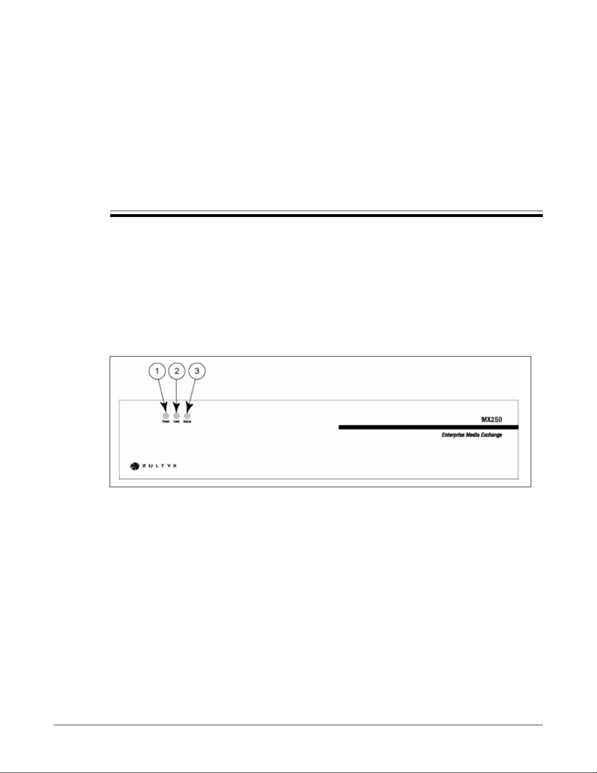
The front panel side of the MX250, as is shown in figure 3-1, has no wiring connectors. Chapter 7,
starting on page 37, describes the LED indicators.
Chapter 3
Figure 3-1 Front Side of MX250
The numbers in figure 3-1 correspond to the following components:
1. Power LED – During normal operation, the Power LED indicates the status of ac power and
battery applied to the MX250.
2. Load LED – During normal operation, the Load LED indicates system service accesses and
storage availability for applications, reports, and voice mail.
3. Status LED – During normal operation, the Status LED indicates the status of firmware
update, fan failure, temperature, console mode, and exceptions.
During system start up and shut down, the MX250 uses all LEDs to indicate procedure
completion. See Chapter 7, starting on page 37, for a description of MX250 LEDs.
11
Page 16
MX250 Hardware Manual
3.3 Rear Side of MX250
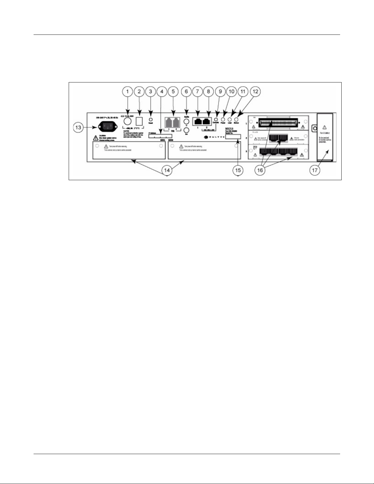
The rear side of the MX250, as shown in figure 3-2, contains the power and communication
interface connectors.
Figure 3-2 Rear Side of MX250
The numbers in figure 3-2 correspond to the following components:
1. Fuse – Provides access to a 6A, 5 x20 mm, time lag fuse, which is in series with the –48V
battery. Replace this fuse only with a fuse of the same rating.
2. DC power input – When this input is connected to an external –48 Vdc battery supply, the
system remains powered when the ac supply is off. See section 4.3 on page 23.
Zultys recommends using the BPS12 as the external supply. Read the BPS12 Hardware
Manual for details on its installation and operation.
3. Reset button – When power to the MX250 is off, pressing this button will turn on the unit.
When power is on, pressing this button for one second initiates a system shut down.
4. IP address – An area to enter the configured IP address assigned to the MX250 with a label or
permanent marker.
5. Analog FXS – Two RJ11 connectors provide two analog FXS ports for connecting fax
machines, analog phones, or modems to the MX250. During a power failure on the MX250,
these circuits connect directly to the first two circuits on the FXO card of the first slot. See
section 3.4.2 on page 14.
6. 3.5 mm audio jacks – The port marked IN provides a 3.5 mm unbalanced input for music on
hold. The source can be stereo or mono with an output impedance of less than 120 Ω and a
level of 5 Vrms (as recommended by IEC 61938). The port marked OUT provides a 3.5 mm
output for connecting to an external speaker system such as an analog paging unit.
7. First Ethernet port – A 10/100Base-T circuit for connecting to any IP device, such as a LAN
switch, router, or IP phone. No in-line power is provided on this circuit. See section 3.4.1 on
page 13.
12
8. Second Ethernet port – A 10/100Base-T circuit for connecting to any IP device, such as a LAN
switch, router, or IP phone. No in-line power is provided on this circuit. See section 3.4.1 on
page 13. This circuit also serves as the console port as defined in section 3.5 on page 18.
Page 17

3. Hardware
9. Console button – Pressing this button during boot up causes the Second Ethernet Port to
become the console port assigned the fixed IP address of 192.168.1.100. Read section 3.5 on
page 18 for instructions on using the console port.
10. Power LED – See section 3.2 and Chapter 7, starting on page 37, for a description of the Power
LED.
11. Load LED – See section 3.2 and Chapter 7, starting on page 37, for a description of the Load
LED.
12. Status LED – See section 3.2 and Chapter 7, starting on page 37, for a description of the Status
LED.
13. AC Input – Provides a universal fused input for ac power. You can insert 100 Vac to 240 Vac
at 47 Hz to 63 Hz. When the dc power input is connected to a –48 V battery, the system
remains powered when the ac power is off. See section 4.3 on page 23.
14. Hard Discs – Two slots which hold the SCSI hard disc drives. The MX250 requires one to
operate. The other serves as a redundant hard disk drive that is mirrored with the first one
in a RAID1 configuration. The system is shipped with one hard disc; a software license is
required to enable RAID1 redundancy of the second disc.
15. Serial Number – This number identifies the main chassis. Refer to this number to identify the
system to a technical support representative or when returning the system for repair or
replacement.
16. Interface slots – Each slot can accommodate one interface card for connection to the PSTN or
an ISP. There are four available types of interface cards:
• FXS: 8 analog subscriber-side circuits using loop start. See section 3.4.2.
• FXO: 8 analog exchange-side circuits using loop start or ground start. See section 3.4.2.
• PCM: 2 full-duplex PCM circuits which support T1 or E1 functionality. See section 3.4.3.
• BRA: 4 full-duplex ISDN BRA S/T circuits. See section 3.4.4.
17. Fan Tray – This removable tray contains two fans and the holder for two AAA batteries used
to power the system’s real time clock. See section 6.2 on page 31.
3.4 MX250 Circuits
The MX250 supports the following circuits:
3.4.1 10/100Base-T
3.4.1.1 Usage
The MX250 has two 10/100Base-T Ethernet circuits. Power over Ethernet is not provided on either
circuit.
• Circuit 1 connects to your LAN and provides data connectivity for the enterprise. You can
then use the MX250 firewall capabilities.
• Circuit 2 can be used as an additional circuit to connect to your LAN or as the console circuit
for initial provisioning, as described in section 3.5.
13
Page 18
MX250 Hardware Manual
3.4.1.2 RJ45 Pin Assignment
All 10/100Base-T Ethernet ports can be routed to a patch panel or to a punch down block for
fanning out to the proper destination. All ports use the RJ-45 connectors. Each circuit can
auto-detect CAT5 cable configuration (straight or crossover) and adapting accordingly.
Ethernet cable wiring must comply with EIA/TIA 568A for the CAT5 10/100Base-T Ethernet. Some
cable suppliers reference EIA/TIA 568A and others reference 568B. The difference is that the green
and orange pairs are terminated to different pins, however, the assignment of pin to signal are
exactly the same on both references. Crossover cables comply with EIA/TIA 568A in all aspects
except signals on pins 1 and 3 at one end appear on pins 2 and 6 at the other end.
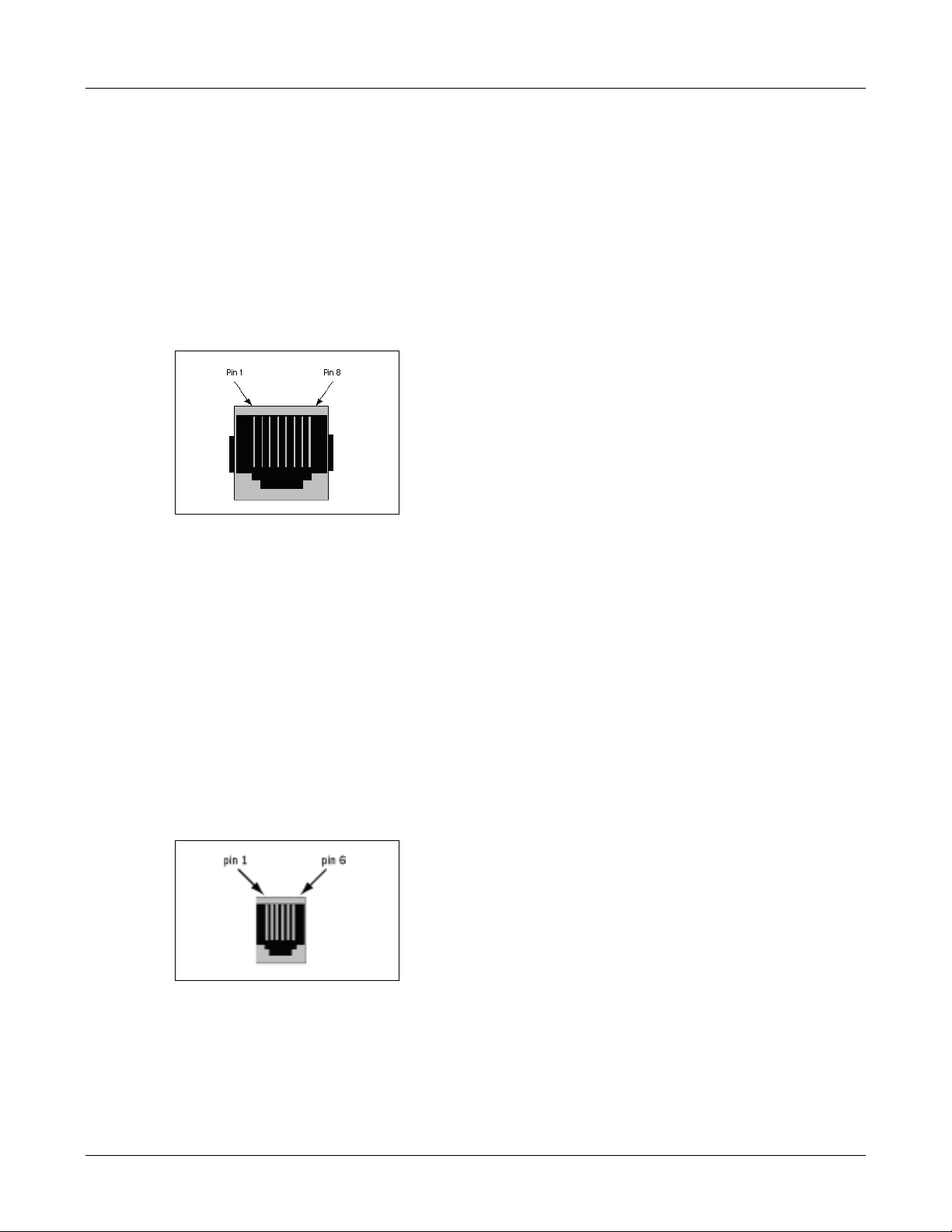
Figure 3-8 shows the pin assignment on an RJ45 connector.
Figure 3-3 Pin Placement of a 10/100 Ethernet Circuit
3.4.2 Analog Circuits
3.4.2.1 Usage
The MX250 supports up to three analog FXO or FXS cards through the interface slots. Each analog
card provides eight analog circuits. FXO circuits support Loop Start and Ground Start protocols;
FXS circuits support Loop Start. Analog circuit protocols are configured through the MX
Administrator software.
3.4.2.2 Analog RJ12 Pin Assignment
Two RJ12 ports on the MX250 connect analog subscriber circuits to the MX250. Figure 3-4 shows
the pin placement of the analog RJ12 connector. Figure 3-5 lists function of each pin.
Figure 3-4 Pin Placement of the Analog Circuit RJ12 Connector
14
Page 19
Pin Signal Name Abbreviation
1 (not connected) —
2 (not connected) —
3Ring 1 R1
4Tip 1 T1
5 (not connected) —
6 (not connected) —
Figure 3-5 Pin Description of the Analog RJ12 Connector
3.4.2.3 Analog 50-Pin Telco Pin Assignment
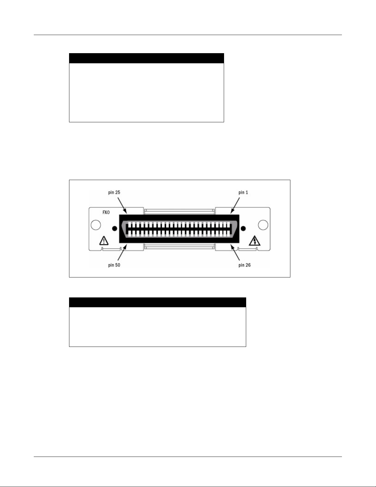
The FXO and FXS interface boards have a 50-pin telco receptacle (female) for connecting analog
circuits to the MX250. Figure 3-6 shows the pin placement on the telco connector of the FXS and
FXO cards. Figure 3-7 shows the function assignment of each pin.
3. Hardware
Figure 3-6 Pin Assignment of a 50-pin Telco Connector on FXO or FXS Card
Pin Signal Name Abbreviation
1 to 8 Tips for circuit 1 to 8 T1 to T8
26 to 33 Ring for circuit 1 to 8 R1 to R8
9 to 25 Unconnected
34 to 50 Unconnected
Figure 3-7 Pin Description of 50-pin Telco Connector
3.4.3 PCM (T1 and E1)
3.4.3.1 Usage
The MX250 supports up to two PCM cards through the interface slots. Each card has two
full-duplex circuits which can be configured for either T1 (1.544 Mb/s) or E1 (2.048 Mb/s). Each
circuit uses one of several supported PSTN or IP WAN protocols. The circuit type and protocol
for each circuit are configured through the MX Administrator software.
15
Page 20
MX250 Hardware Manual
3.4.3.2 PCM RJ45 Pin Assignments
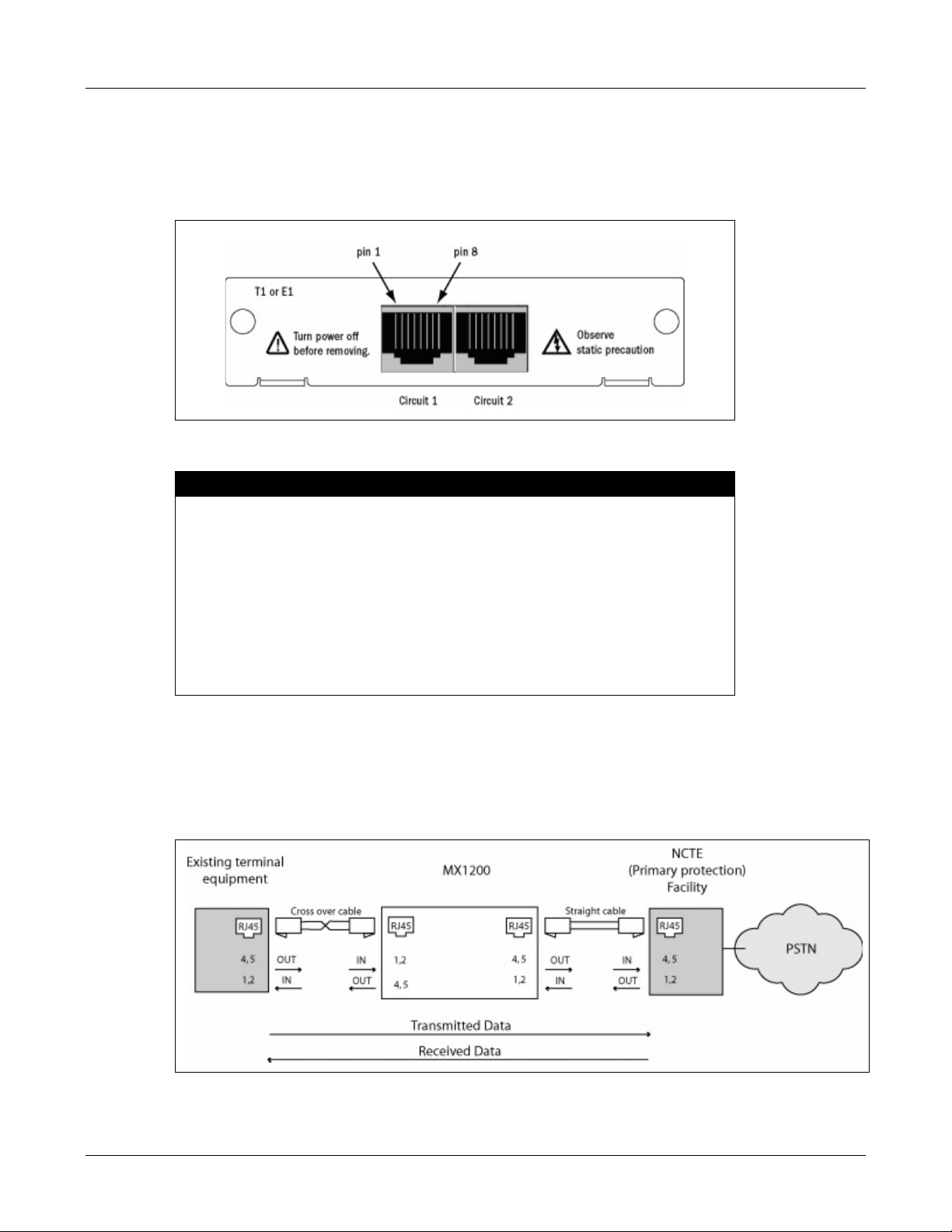
Each circuit on the PCM card terminates on an RJ45 connector. Figure 3-8 shows the pin
placement of each pin of the PCM. Both circuits have the same pin assignment. Figure 3-9 shows
the function assignment of each pin.
Figure 3-8 Pin Assignment of PCM Circuits on PCM Card
Pin Signal Name Circuit Source
3NC AA common
6NC AA common
7NC AA common
8NC AA common
1 Received Data, ring BAa Facility
2 Received Data, tip BAb Facility
4 Transmitted Data, ring BBa MX250
5 Transmitted Data, tip BBb MX250
Figure 3-9 Pin Description of a PCM Circuit
16
Figure 3-10 displays the connection of PCM circuits to the network or other equipment. Use a
straight cable to connect the MX250 to the network jack. Use a crossover cable to connect the
MX250 to an existing terminal system (such as an existing PBX). Figure 3-10 also displays MX250
pinouts and pinouts typically used for terminal and network equipment. Consult the
documentation for specific devices to confirm the pin assignment.
Figure 3-10 Wiring the PCM Circuits to the Network or Other Equipment
Page 21
Important Do not use Ethernet cables for connecting the PCM circuits. The cables that are
used for PCM are different from those used for Ethernet. Ensure that the cable
you use are properly wired as shown in figure 3-9.
3.4.4 ISDN BRA (S/T Interface)
3.4.4.1 Usage
The MX250 supports up to three BRA cards through the interface slots. Each card has four S/T
circuits. The protocol for each circuit is configured through the MX Administrator software.
3.4.4.2 BRA RJ45 Pin Assignments
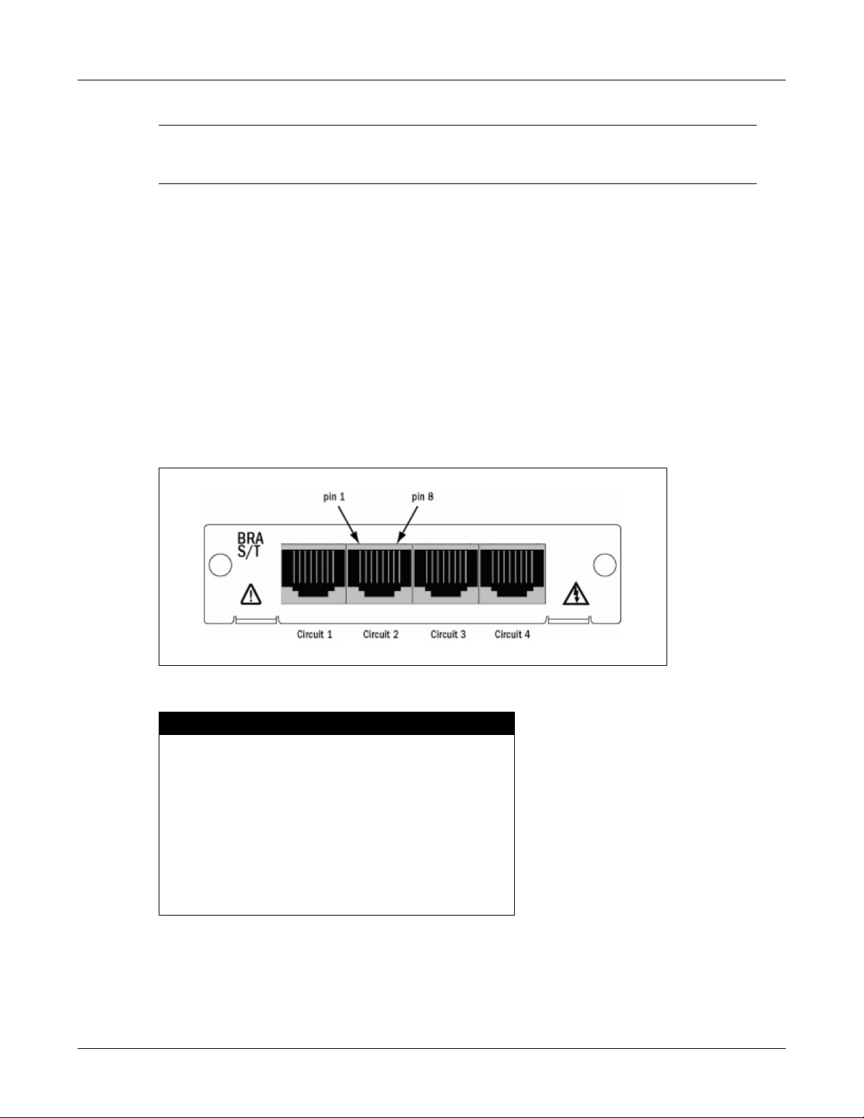
Each ISDN BRA circuit terminates on an RJ45 connector. Figure 3-11 shows the pin assignment
for the RJ45 connectors on the BRA card. Each circuit on the BRA card has the same pin
assignment. Each connector has the same pin assignment. Figure 3-12 shows the function
assignment of each pin.
3. Hardware
Figure 3-11 Pin Assignment of the ISDN BRA (S/T) Circuits on BRA Interface Card
Pin Signal Name Circuit
1not connected NC
2not connected NC
3Transmit + (tip) Tx+
4Receive + (tip) Rx+
5 Receive – (ring) Rx–
6 Transmit – (ring) Tx–
7not connected NC
8not connected NC
Figure 3-12 Pin Description of the ISDN BRA (S/T) Circuit
17
Page 22

MX250 Hardware Manual
3.5 Console Mode
Console mode provides a method of to accessing the MX250 in a known, predefined state.
Console mode is used to initially configure the IP address of the system or to recover a lost or
unknown IP address. Putting the MX250 in console mode during power up.
Before putting the MX250 into console mode, you should disconnect the Ethernet ports from your
system. This will ensure that there are no conflicts with other devices on your network.
Important Ensure that the Ethernet cables are disconnected from the MX250 before entering
console mode. Failure to do so may disturb other devices on the LAN.
When the MX250 is in console mode, you can connect a computer to the Second Ethernet Port
(item 8 in figure 3-2 on page 12). The IP address used to access the MX250 depends whether the
MX250 was placed in console mode during normal operation or during power up.
3.5.1 Console Mode Activated During Power Up
Pressing the Console button during power up sets the console port to a known fixed IP address
so you can communicate with the MX250.
To put the MX250 into console mode from power up:
1. Disconnect the Ethernet ports from your system.
2. Ensure power to the MX250 is turned off.
3. Press and hold the Console button.
4. Turn power on the MX250.
5. Keep the Console button held for about 60 seconds.
The MX250 indicates it has entered console mode with the Status LED as shown in figure 7-5.
To communicate with the MX250 in console mode, connect your PC directly to the Second
Ethernet Port (item 8 in figure 3-2 on page 12). To access the MX250, configure your PC’s network
interface with an IP address of 192.168.1.111 with a subnet mask of 255.255.255.0.
Access the MX250 at IP address 192.168.1.100 using an HTML browser or the MX250
administration software if you already have it installed on the computer. For details on how to
configure the MX250, see the MX Administration User’s Manual.
To exit the console mode you must shut down and power cycle the MX250. To turn the power off,
either use the shutdown command from the MX administration software or press the reset button
(item 3 in figure 3-2 on page 12).
3.5.2 Console Mode Activated During Normal Operation
If you are unable to access your system through the User Interface, you can allow Zultys Technical
Support to access your system by entering Run Time Console Mode during normal MX operation.
You should enter Run Time Console Mode only as instructed by a member of Zultys Technical
Support.
18
Pressing the Console button during normal operation puts the MX250 into console mode without
changing its IP addresses.
Page 23

3. Hardware
To put the MX250 into console mode during normal operation:
1. Disconnect the Ethernet ports from your system.
2. Press and hold the console button for about two seconds.
The MX250 indicates it has entered Console mode with the Status LED as shown figure 7-5.
Once the MX250 is in console mode, you can access it at the assigned IP address.
To exit the console mode press and hold the console button for two seconds. The MX250 exits the
console mode and restores the status of the LEDs.
19
Page 24

MX250 Hardware Manual
20
Page 25

Preparation
4.1 Introduction
This chapter explains:
• guidelines for selecting a site
• the tools required for installation
• types of cables for the voice and data circuits
The MX250 is designed to be permanently installed within a network room in a 19" equipment
rack. You must carefully install the MX250 system to ensure its proper operation.
Chapter 4
Warning The MX250 is designed to be installed by qualified personnel only. Installation by
unqualified individuals may result in bodily injury and damage to the MX250 and
surrounding equipment.
Warning This equipment is to be installed and maintained by service personnel only as
defined by AS/NZS 3260 Clause 1.2.14.3 Service Personnel.
Warning The MX250 must be installed in a secure location that has access restricted to
qualified personnel only. Placing the MX250 in a location accessible by unqualified
individuals may result in bodily injury and damage to the MX250 and surrounding
equipment.
4.2 Selecting a Site
The following criteria must be considered when selecting a site for your MX250 system:
21
Page 26

MX250 Hardware Manual
4.2.1 Earth Ground
The resistance between the equipment frame and earth ground (per UL 60950, paragraph 2.6.3.3)
should be less than 0.1 Ω. An adequate earth ground is normally implemented with a copper rod
(about 15 mm or 0.6" diameter) driven at least 4 m (12 ft) into moist soil. Improve conductivity by
adding salt or magnesium sulphate to the soil surrounding the rod to a depth of 200 mm (0.6 ft);
periodic replenishing may be required.
4.2.2 Temperature
Install the MX250 where the temperature remains between 0°C and 40°C.
Warning If you install the MX250 in an environment where the temperature is outside the
range 0°C ~ 40°C, this may result in bodily injury and damage to the MX250 or
surrounding equipment. You will also void your warranty.
4.2.3 Ventilation
The MX250 requires space on both sides for ample air flow. The internal fans move the air from
left to right as you look at the front of the equipment.
Important Do not cover the slots and openings on the equipment. These are provided for
ventilation and protection against overheating.
4.2.4 Cable Lengths
Cable placement to associated equipment is an important site criteria. Figure 4-1 shows the
minimum and maximum length of any cables that you connect to the MX250.
Circuit Connector Minimum Distance Maximum Distance
T1 or E1 RJ45 0 1.8 km (6000 ft.)
Analog RJ11 0 1 km (3000 ft)
BRA S/T RJ45 5 m (15 ft) 25 m (75 ft)
10/100BaseT RJ45 0 100 m (300 ft)
48 V battery Molex Mini Fit 0 3 m (10 ft)
Audio 3.5 mm 0 3 m (10 ft)
Figure 4-1 Minimum and Maximum Cable Lengths
The distance listed in the table for the T1 or E1 circuits is the maximum distance between the
MX250 chassis and the nearest T1 or E1 signal repeater. The actual cable used to connect to the
demarcation point may be significantly shorter.
The battery input to the MX250 uses a special connector. Zultys supplies a cable to connect to it,
the length of which is shown in the table.
22
Page 27

4.2.5 Other Site Requirements
Select a site where liquids or objects will not fall onto the equipment and that foreign objects will
not be drawn into the ventilation holes.
4.3 Power Requirements
The MX250 uses ac power as its primary power source. You can connect the BPS12 to the MX250
to provide continued operation in the event of loss of ac power.
Warning The MX250 is inoperable when ac power fails and you have not installed a battery
backup system, or when the power of the battery backup system is exhausted.
4.3.1 AC input
The total ac power input on the MX250 is 100 W, which includes power for ringing and battery
feed to analog telephones and fax machines.
The MX250 has a universal ac input that you can connect to a standard electric outlet (100 Vac to
240 Vac, 47 Hz to 63 Hz).
4. Preparation
4.3.2 –48 V Battery
Connecting a BPS12 battery power supply to the MX250 continues operation in the absence of ac.
Zultys recommends using the BPS12 as the external supply in addition to connecting to the ac
power source. Connect to the BPS12 as described in the BPS12 Hardware Manual. The BPS12
battery unit sold by Zultys requires 3 RU of rack space and a separate ac source.
Warning You must use the BPS12 battery system provided by Zultys, or use a battery source
that is supplied by a Listed or Certified power supply providing SELV power. This
is required because the –48 Vdc directly powers the SELV of the system.
The BPS12 battery unit sold by Zultys requires 3 RU of rack space and a separate ac supply.
Important Zultys strongly recommends use of the BPS12 for all installations of the MX250.
During power outages, this provides a dc source from which the MX250 can
detect capacitive levels. This allows the MX250 time to initiate a proper shutdown
of its database.
4.3.3 Uninterruptable Power Supply (UPS)
Although connecting the ac input to a UPS allows the system to operate during a power outage,
Zultys does not recommend this solution since most UPS devices do not provide the longevity
demanded by telecommunications applications. Most UPS devices are scaled too small and can
only providing a short standby duration.
23
Page 28

MX250 Hardware Manual
The MX250 monitors the battery voltage, which allows the system to provide an alert or shut
down the system when battery voltage declines below a specified value. The MX250 has no
provision for monitoring the voltage of the component batteries of an external UPS.
4.4 Electrostatic Discharge (ESD) Precautions
Almost all electronic components can be damaged by ESD during handling. Component damage
can occur at ESD voltages as low as 50 V. A person walking across a nylon carpet can easily
generate voltages in excess of 5,000 V.
Observe the following guidelines to help prevent ESD damage when installing or servicing the
MX250 system or any other electronic device.
• Assemble or disassemble equipment only in a static-free work area.
• Use a conductive work surfaces (such as an antistatic mat) to dissipate static charge.
• Wear a conductive wrist strap and lab coat to dissipate static charge accumulation.
• Minimize handling of assemblies and components.
• Keep replacement parts in their original static-free packaging.
• Remove all plastic, foam, vinyl, paper, and other static-generating materials from the
immediate work area.
• Use tools that do not create ESD.
In addition to these precautions, do not handle connector pins or touch onboard components to
avoid contamination.
Caution You can easily damage the MX250 by failing to follow these instructions. You may
delay installation, or cause the equipment to prematurely fail. Such failure may lead
to a disruption of the service provided by the equipment. You may also void your
warranty.
24
Page 29

Mounting the MX250
5.1 Introduction
This chapter explains the method for mounting the MX250 into the equipment rack.
Important You must read the section on site selection and preparation before starting to
install the MX250. Refer to chapter 4, starting on page 21.
Chapter 5
5.2 Equipment Rack
Zultys recommends installing the MX250 in the same secured wiring closet as the networking
equipment to which it connects. Devices typically connected to the MX250 include the firewall,
the LAN switch, the battery power system, and the provisioning computer.
All connections to the MX250 system are made at the rear panel. Leave space next to the rear
panel for cables and for personnel installing the system.
Warning The MX250 system must be properly grounded (earthed). When the equipment is
mounted in an equipment rack, the rack must be connected to ground (earth). See
section 4.2.1 on page 22 for details on the proper grounding technique.
Warning Ensure that the rack is properly mounted to the floor or has properly fitted
stabilizers so that it cannot move and will not tip over. If the rack tips over, it may
cause you bodily injury and may damage the equipment.
When mounting equipment in the equipment rack, place the equipment at the bottom of the rack
if it is the only equipment in the rack. If you mount the equipment in a partially filled rack, load
the rack from the bottom to the top with the heaviest equipment at the bottom of the rack.
5.3 Tools Required
Figure 5-1 shows the required tools for mounting the MX250 into the equipment rack.
25
Page 30
MX250 Hardware Manual
Tool Purpose
manual screwdriver, Phillips or crosshead,
sized to fit M3 screwhead
manual screwdriver, Phillips or crosshead,
sized to fit M4 screwhead
manual screwdriver, Phillips or flat-head,
sized to fit 12-24 screws
power screwdriver, Phillips or flat-head,
sized to fit 12-24 screws
manual screwdriver, Phillips or flat-head,
sized to fit M6 screws
power screwdriver, Phillips or flat-head,
sized to fit M6 screws
ESD-preventative wrist strap to prevent harmful electrostatic discharge onto
Figure 5-1 Required Tools for Installation
to fasten the modules into the MX250
to fasten the mounting brackets and cable
management brackets to the sides of MX250 chassis
to loosely screw in place mounting screws of chassis
to rack
to tighten mounting screws of chassis to rack
to loosely screw in place mounting screws of chassis
to rack
to tighten mounting screws of chassis to rack
electronic equipment during installation
5.4 Installing Brackets for Cable Management
The MX250 main chassis is supplied with two optional plastic brackets for cable management.
Cable management on the MX250, requires the installation of the plastic brackets on the rear side
of the chassis. The plastic brackets cannot be installed on the front side of the MX250 chassis.
Follow these instructions for proper installation of the plastic brackets for cable management:
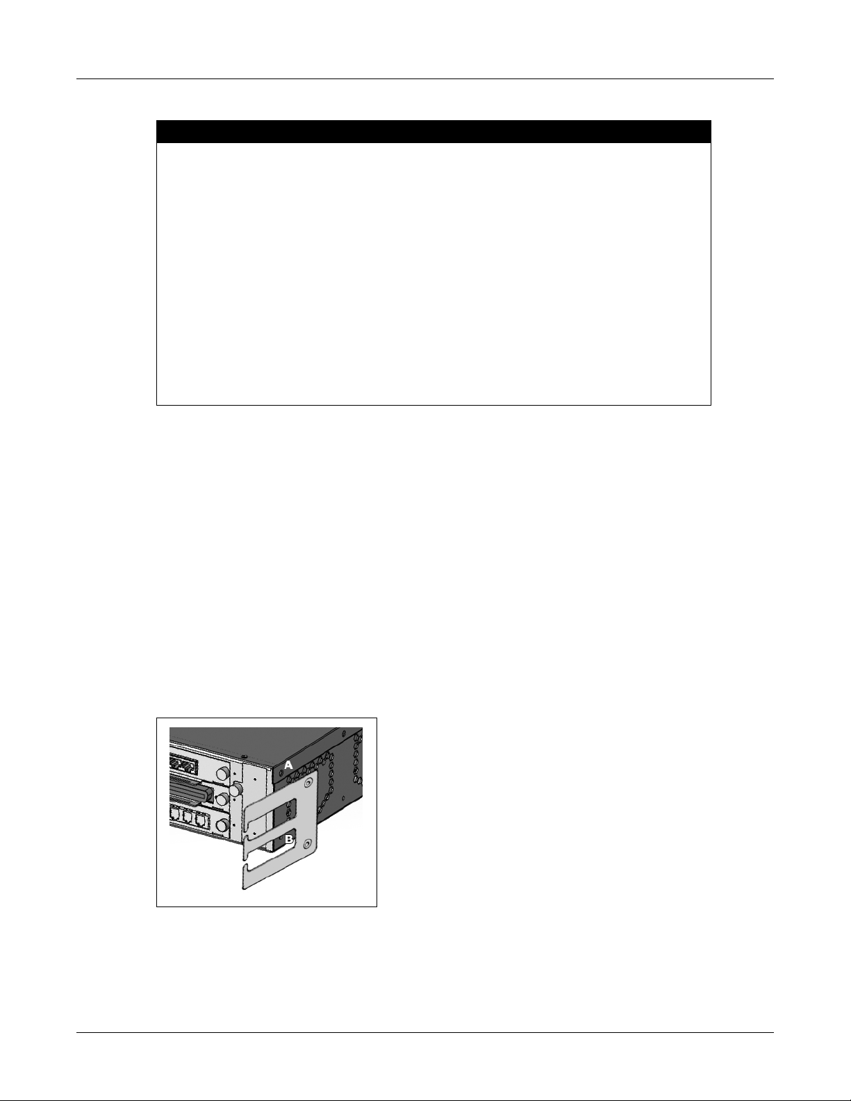
1. From the right side of the rear face, remove the M4 screw from position A in figure 5-2.
2. Hold a plastic bracket for cable management against the chassis with the plastic fingers
pointing away from the chassis and the countersunk holes on the outside. Ensure the holes
on the plastic bracket are aligned with the holes at positions A and B on the chassis.
3. Screw the plastic bracket into place using two M4x6 screws (58-20002-00) at positions A and
B on the chassis.
4. Install the other plastic bracket by repeating steps 1 to 3 for the left side of the rear panel.
Figure 5-2 Cable Management for Mounting from Front or Middle
26
Page 31
Warning Use only the M4x6 screws (58-20002-00) to secure the plastic bracket to the chassis.
Using a longer length screw may protrude too far into the chassis and cause
internal damage to the boards.
5.5 Installing Mounting Brackets on Chassis
The MX250 main chassis is supplied with two mounting brackets that you must fasten onto the
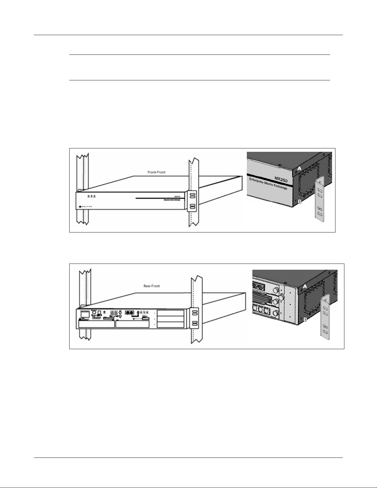
chassis prior to installing it into a 19" equipment rack. The system can be mounted into one of the
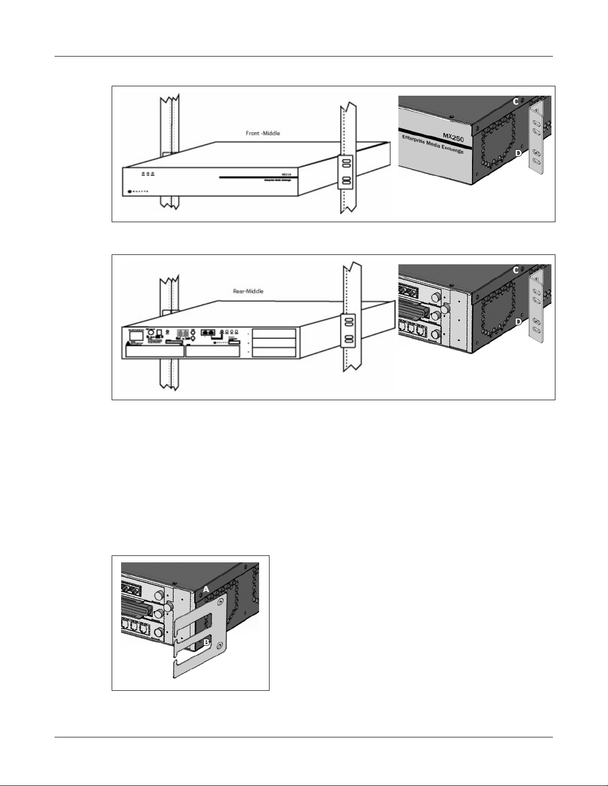
four following positions:
• Mounting the chassis from the front side, as shown in figure 5-3.
5. Mounting the MX250
Figure 5-3 Mounting Brackets in the Front Side of Chassis
• Mounting the chassis from the rear side, as shown in figure 5-4.
Figure 5-4 Mounting Brackets in the Rear Side of Chassis
• Mounting the chassis from the middle of the front side, as shown in figure 5-5.
• Mounting the chassis from the middle of the front side, as shown in figure 5-6.
Follow these instructions to install the mounting brackets on the MX250 chassis:
1. Select the bracket position from the list of four mounting options. Identify the figure that
depicts the preferred bracket position and refer to that figure during the mounting
procedure.
27
Page 32
MX250 Hardware Manual
Figure 5-5 Mounting Brackets in the Middle of Front Side of Chassis
Figure 5-6 Mounting Brackets in Middle of Rear Side of Chassis
2. Remove the M4 screw from position A (front side installation) or position C (middle of the
front side or middle of the rear side installation). For a rear side installation, remove screws
from position A and position B. This step removes the plastic Cable Management bracket
from the chassis.
3. Hold a mounting bracket against the chassis so the holes on the mounting bracket are
aligned with positions A and B (front side) or positions C and D (middle of the front side or
middle of the rear side installation).
For a rear side installation, hold the plastic bracket against the chassis and the mounting
bracket next to the plastic bracket, as shown in figure 5-7.
28
Figure 5-7 Cable Management for Mounting from Front or Middle
Page 33

4. Fasten a mounting bracket using two M4x6 screws (58-20002-00) at positions A and B (front
side) or positions C and D (middle of the front side or middle of the rear side installation).
For a rear side installation, fasten the mounting and plastic bracket using two M4x10 screws
(58-2005-00) at positions A and B.
Warning Use only the M4x10 screws (58-20005-00) to secure the plastic bracket and
mounting bracket for a rear side installation. Use only M4x6 screws (58-20002-00)
to secure the mounting bracket for all other installation configurations. Using a
longer length screw may protrude too far into the chassis and damage the internal
boards. Using a shorter length screw may not securely fasten the mounting bracket
to the chassis and cause the chassis to fall after mounting to the equipment rack.
5. Repeat step 2 through step 4 for the other side of the chassis.
5.6 Installing the Chassis into the Equipment Rack
1. Ensure that the two mounting brackets have been fastened to the chassis as described in
section 5.5 on page 27.
5. Mounting the MX250
2. Hold the main chassis in place on a 19
brackets aligned against the holes in the front of the rack.
" equipment rack, with the flanges of the mounting
Warning You need two people to lift and install the MX250. Grasp the chassis underneath
the lower edge and lift with both hands. To prevent injury, keep your back straight
and lift with your legs, not your back.
3. While holding the chassis in place, use a hand screwdriver to screw the four 12-24 mounting
screws into place on the flanges.
4. Once mounted in position with the screws in place, use a power screwdriver to tighten all
four screws.
1
Do not tighten the screws.
1. The MX250 is supplied with four 12-24 mounting (imperial) screws and M6x10 mounting (metric) screws for conventional 19” equipment racks. Use either the 12-24 mounting screws or the M6x10 mounting screws, depending on the
thread pattern of equipment rack.
29
Page 34

MX250 Hardware Manual
30
Page 35
Connecting, Wiring, and Configuring
6.1 Introduction
This chapter describes the following procedures:
• installing the batteries that power the real time clock
• configuring the IP addresses on the MX250
• connecting the MX250 to your networks
• configuring the MX250
Chapter 6
6.2 Installing Batteries for Real Time Clock
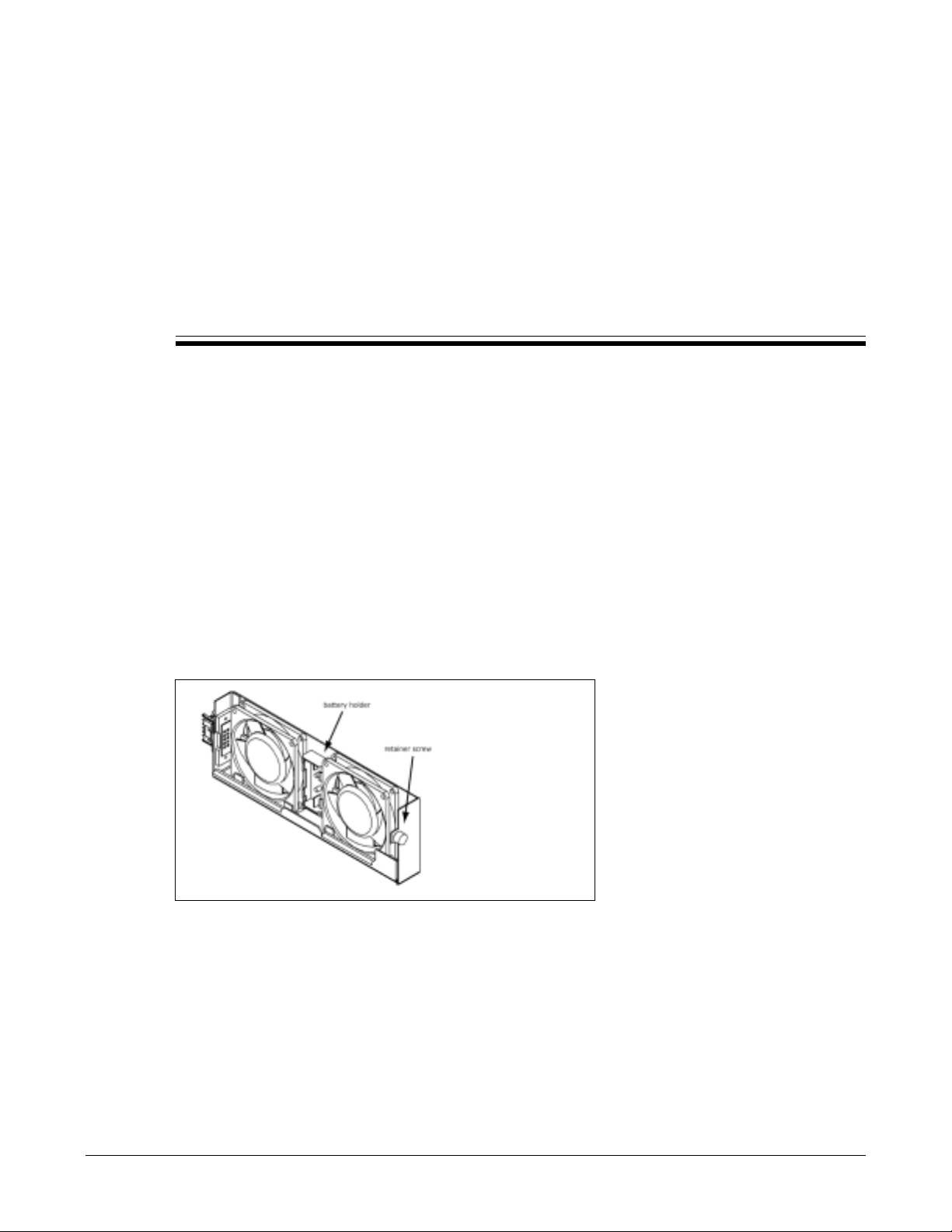
Before installing the MX250 chassis into the network rack, you must install two AAA batteries into
the fan tray to power the real time clock on the MX250. The position for these batteries is on the
fan tray shown in figure 6-1. To install the batteries:
Figure 6-1 Fan Tray on MX250
1. Ensure power is not applied to the MX250.
2. Locate the removable fan tray (item 17 in figure 3-2) on the rear side of the MX250.
3. Unscrew with a screwdriver the captive retaining screw on the face plate.
4. Gently slide the fan tray out of the MX250 chassis.
5. Locate the plastic battery slots between the fans. Identify the battery polarity markings.
31
Page 36

MX250 Hardware Manual
6. Insert two AAA batteries into the battery slots as indicated by the polarity markings.
7. Gently re-insert the fan tray into the MX250 chassis.
8. Tighten the captive retaining screw on the face plate.
6.3 Setting the IP Addresses
The external IP address of the MX250 when it is shipped from the factory is 192.168.27.254. The
internal IP addresses of the MX250 when it is shipped from the factory start at 172.16.0.1.
For most applications, you should change these IP addresses before connecting the MX250 to
your network. Then configure the system through the MX Administrator software as described
in the MX Administration User’s Manual.
6.3.1 Activating Console Mode
Pressing the Console button during power up sets the console port to the fixed IP address of
192.168.1.100 so you can communicate with the MX250. To activate console mode:
1. Disconnect the Ethernet ports from your system. This prevents the MX250 from conflicting
with other network devices.
2. Ensure power to the MX250 is turned off.
3. Press and hold the Console button.
4. Turn power on the MX250 by using the ac cord to connect the ac input port to the wall outlet.
5. Keep the Console button held for about 60 seconds.
The MX250 indicates it has entered console mode with the Status LED as shown in figure 7-5.
6.3.2 Accessing the User Interface
1. Connect your PC to the console port (item 8 in figure 3-2). Configure your PC’s network
interface with an IP address of 192.168.1.111 and a subnet mask of 255.255.255.0.
2. Access the MX250 Download page by opening your HTML browser and entering the IP
address 192.168.1.100.
3. Click on Download Administration UI, then open the file to install the software.
This should open the Zultys MX Administrator Login display; if the display does not appear,
double click the MX Admin icon.
4. Enter the following values in the Login panel (logins and passwords are case sensitive):
• Login: Administrator
• Password: zultys
• URL: 192.168.1.100
32
Page 37

6. Connecting, Wiring, and Configuring
6.3.3 Changing the IP Addresses
1. Select Provision | System Settings from the main menu, then click on the IP Addresses tab.
Enter the desired IP addresses in the Ethernet LAN section. Press the Apply button to save
the panel contents
2. UI will display panel stating that a reboot is required to save IP address changes. Press
Reboot button to apply changes and restart system.
User Interface will lose connection with the MX250 as it shuts down and then restarts. When
system restarts, it will not be in console mode.
3. Disconnect the PC from the console port.
4. Reconfigure PC to obtain TCP/IP address automatically.
5. Connect PC to the network to which the MX250 will be connected.
6.4 Connecting the MX250 to the Networks
6.4.1 Cables Required for Installation
The number and types of cables required for your the system depends on the enabled system
options and your network configuration. Figure 6-2 lists the cables which may be required.
Cable
50-pin telco 3 Analog FXO or FXS circuits
RJ45, BRA S/T wiring, Cat 5 12 ISDN BRA ports to PSTN or the IP WAN
RJ45, USOC wiring, Cat 5 4 T1 and E1 ports to PSTN or the IP WAN
RJ11 cables 2 Analog circuits to telephones, fax machines, or other accessories
RJ45, 258A wiring, Cat 5 2 Ethernet to an IP-enabled device, firewall, or provisioning console
DC power 1 Battery circuit to an external battery source
3.5 mm audio 1 Music on hold input
Figure 6-2 Maximum Number of Cables for MX250
For T1 and E1 circuits, Tx must be wired to Rx. This may require straight or crossover cables.
Warning To reduce the risk of fire, use only 0.4 mm² (26 AWG) or larger wire for all
telecommunications circuits.
Contact your sales representative for ordering numbers for cables on the MX250.
6.4.2 Connecting Procedure
Refer to figure 3-2 to locate and identify all MX250 ports.
Max
Qty Used to connect
1. Connect the MX250 to the LAN through Ethernet Port 1.
33
Page 38
MX250 Hardware Manual
2. Connect all subscriber stations.
• If you have IP phones or devices enabled with softphones, connect a LAN switch to an
Ethernet port, then connect the IP phones or devices with softphones to the switch.
• Connect analog telephones, fax machines, or modems through the FXS ports (item 5 of
figure 3-2) or ports on the FXS interface card.
3. Connect voice lines to the PSTN.
• Connect T1 or E1 circuits through the PCM card’s RJ45 connectors. Configure circuit type
and protocol for each circuit using the MX Administrator software.
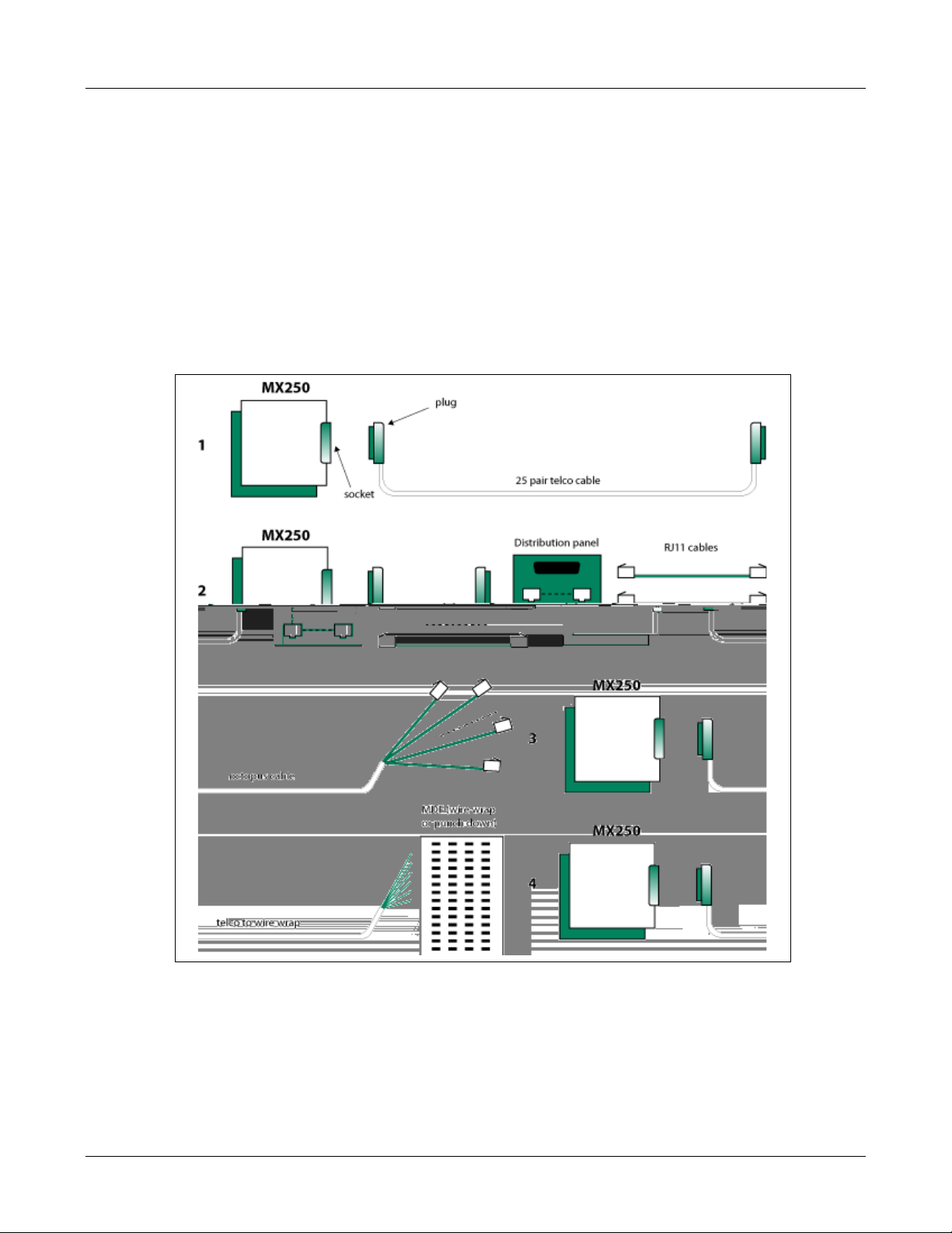
• If you have analog PSTN lines, use the telco connector on the FXO interface card. Figure
6-3 shows the several options in which you can connect to the PSTN using this connector.
34
Figure 6-3 Wiring options for FXO on MX250
4. Connect data lines to the IP WAN.
• Connect the MX250 to T1 or E1 circuits through the RJ45 ports on the PCM card.
Configure circuit type and protocol for each circuit using the MX Administrator software.
Page 39

6. Connecting, Wiring, and Configuring
• To connect to the WAN using external equipment, connect the external equipment to the
MX250 through one of the two Ethernet ports.
5. If Music on Hold is provided by an external source, connect that source to the audio input
(item 6 of figure 3-2).
6. Ensure that power is not provided to the system.
7. Plug the ac cord into ac input. See figure 3-2 to identify the ac input.
Danger Always use the provided power cord to power the MX250; contact your Zultys
representative if this is unsuitable. The provided power cord has a separate ground
(earth) connector and must be inserted in a power socket that provides a protective
ground (earth) contact. Do not negate this protection by using an extension cord
(power cable) that does not carry the protective grounding conductor.
Warning The power supply cord is used as the main disconnect device. Ensure the power
socket is located or installed near the equipment and is easily accessible.
Warning Zur sicheren Trennung des Gerätes vom Netz ist der Netzstecker zu ziehen.
Vergewissern Sie sich, daß die Steckdose leicht zugänglich ist.
Warning Le cordon d’alimentation est utilisé comme interrupteur général. La prise de
courant doit être située ou installée à proximité du matériel et être facile d’accés.
Danger The power cord provides the safety ground for the MX250. Keep this cord properly
connected at all times, even if the equipment is not powered by the ac mains.
Caution Do not place objects on the power cord. Run the power cord so people cannot step
on or trip on the power cord.
8. Plug the ac power cord into the wall outlet.
Warning Do not overload wall outlets as this might result in electric shock.
9. If you purchased the battery option, plug in the –48Vdc supply into the dc power input (see
item 2 of figure 3-2). Ensure that power to the battery is off before making this connection.
6.5 Configuring the MX250
1. Open the UI by double clicking the MX Admin icon.
35
Page 40

MX250 Hardware Manual
2. Enter the following values in the Login panel:
• Login: Administrator
• Password: zultys
• URL: Enter the configured IP address
For details on configuring the MX250, see the MX Administration User ’s Manual.
36
Page 41

LEDs
7.1 Introduction
This chapter describes how the various indications for each LED on the MX250. The three LEDs
on the front have the same indication as the three LEDs on the rear of the MX250. All LEDs are
controlled by the same PCB.
7.2 During Startup
During startup, the LEDs indicate the progression of the startup process, as indicated in figure
7-1. None of the LEDs shows any red during any portion of this startup phase.
Chapter 7
State Power Load Status
Power Off Off Off Off
Boot code running Orange Off Off
Linux running on SC Flash Green Off Off
Disk mirroring and
maintenance
SC application running Green Orange Off
All boards operational Off Green Orange
Applications loaded Green Green Orange
Configurations loaded Green Green Flash Green
System Ready
Figure 7-1 Conditions For LEDs on MX250 During Normal Startup
a.
Immediately after your system is ready, the Power LED will begin blinking red and green if your MX250
is not connected to a BPS12 power supply.
If there is an error during startup, the LEDs indicate the nature of the problem, as indicated in
figure 7-2. At least one of the LEDs is off, at least one of the LEDs is red, and at least one LED is
flashing.
a
Flash Green Flash Orange Off
Green Green Green
37
Page 42

MX250 Hardware Manual
State Power Load Status
Boot code failure undefined undefined undefined
Linux failure on SC Flash red Off Off
Configuration failure Red Flash red Off
Disc failure Off Red Flash red
Telecom board failure Red Off Flash red
Internal software fault see figure 7-3 Flash red Flash red
Figure 7-2 Conditions For LEDs on MX250 During Abnormal Startup
7.3 Operational System
There are three LEDs on the front of the chassis and three LEDs on the rear of the chassis. The
meanings of the LEDs is described in figure 7-3, figure 7-4, and figure 7-5.
The MX250 indicates that the battery is low if the magnitude of the voltage falls below 46 V ±5%.
The MX250 indicates that the battery is very low if the magnitude of the voltage falls below 44 V
±5%.
When the MX250 is running normally and connected to a BPS12 power supply, all LEDs are
green. Also, when the MX250 is operational, none of the LEDs is off.
Status Colors
AC power off, battery off clear
AC power on, battery normal, system connected to BPS12 power supply green
AC power on, battery normal, system is not connected to BPS12 power supply green flash red
AC power on, battery low or very low green flash orange
AC power off, battery OK orange
AC power off, battery low orange flash red
AC power off, battery very low fast flash red
Figure 7-3 Power LED Pattern Interpretation – Startup is Completed
7.4 Cluster LEDs
MX Clusters is a software option that allows you to connect multiple MX250 systems to operate
as a single MX unit. Each MX250 system that is a member of an MX cluster is referred to as a node.
An MX system that is a component of a cluster is configured as one of three types of cluster nodes:
master, member, or standby. Refer to the MX Administrator’s Manual for more information on
MX Clusters.
7.4.1 Master System LEDs
Under normal operating conditions, the LEDs on the master system of a cluster operate
identically to a standalone MX system. If the cluster is licensed and configured for redundancy,
the Status LED flashes orange (250 ms) and off (250 ms) when the cluster redundancy state is
Redundancy Failed. Refer to the MX Administrators Manual for information on configuring
Clusters.
38
Page 43

Status Colors
System load is light with all of these conditions:
— access to system services < 80%
— application and report storage < 80%
— voice mail storage < 80%
Load is medium because of at least one of these conditions:
— access to system services > 80% and < 90%
— application and report storage > 80% and < 90%
— voice mail storage > 80% and < 90%
Load is heavy because of at least one of these conditions:
— access to system services > 90%
— application and report storage > 90%
— voice mail storage > 90%
Figure 7-4 Load LED Pattern Interpretation – Startup is Completed
Status Colors
Firmware update in progress green flash orange
Firmware update failure orange
Fan failure flash red orange
Temperature too high flash red off
Redundancy (Clusters) fails after being enabled. fast flash orange
Fan failure and temperature too high flash red, off, orange, off
Console Mode is active flash green, red, orange, off
Error in entering Console Mode fast flash red
Syslog event threshold exceeded red
Normal green
Figure 7-5 Status LED Pattern Interpretation – Startup is Completed
green
orange
red
7. LEDs
7.4.2 Member System LEDs
The Load LED of each member MX250 system always flashes green (250 ms) and off (250 ms).
7.4.3 Standby System LEDs
In normal mode:
• The Load LED of the standby MX250 system flashes green (250 ms) and off (250 ms) when the
standby is fully operational.
• The Load LED is off when the MX system is initializing. During this time, the hard drive of the
standby node is copying the contents of the master node.
In switchover mode, the Load LED flashes green (250 ms) and orange (250 ms).
39
Page 44

MX250 Hardware Manual
7.5 System Shut Down
You can initiate a shutdown of the MX250 from the Administrative UI as described in the MX
Administrators Manual. On the MX250 you can also shut down the system with the power
button.
When you shut down the MX250, all applications are gracefully shutdown and Linux is
terminated properly. The stages of this shut down are shown by the LEDs as described in figure
7-6.
The MX250 will shut down automatically.
State Power Load Status
Normal see figure 7-3 Green Green
Shut down initiated Green Green Flash Orange
Applications shut down Green Off Off
Linux shut down Flash Green Off Off
Power off Off Off Off
Figure 7-6 Conditions For LEDs on MX250 During Shut Down
40
Page 45

Maintenance and Use
8.1 Introduction
This chapter describes how you should ensure that the MX250 continues to operate.
Warning Only trained and qualified personnel should be allowed to maintain the MX250.
Chapter 8
8.2 Usage
Warning Do not use the MX250 to report a gas leak when in the vicinity of the gas leak.
8.3 Servicing
To ensure the operation of the real time clock when the system is off, you should replace the AAA
batteries in the fan tray at least once per year. See section 6.2 on page 31 for instructions on
replacing these batteries.
Caution The fan tray batteries are the only parts inside the MX250 that you can repair or
replace yourself. Refer servicing to only qualified service personnel.
For proper servicing of these products, return them to the distributor from whom you purchased
them or to Zultys.
8.4 Disposal
When the system is no longer of any use, you may return it to Zultys, or the Zultys distributor
from whom you purchased the equipment, for proper disposal.
41
Page 46

MX250 Hardware Manual
42
Page 47

Acronyms
A Ampere
ac alternating current
ANSI American National Standards Institute
B8ZS bipolar with 8 zeroes substitution
b/s bits per second
BRA Basic Rate Access to ISDN
CAS channel associated signaling
Appendix A
CCITT International Telegraph and Telephone Consultative Committee
CCS common channel signalling
CO central office
CPE customer premises equipment
CSU channel services unit
dc direct current
DCE data circuit terminating equipment
DMM digital multimeter
DS1 digital signal level 1 (1.544 Mb/s)
DSU digital services unit
DTE data terminal equipment
E1 digital signal, level 1, specified by ITU-T (2.048 Mb/s)
ESD electrostatic discharge
ESF extended superframe format for t1, comprising 24 frames in a superframe
ETSI European Telecommunication Standards Institute
FCC Federal Communications Commission
FDL facility data link
FSK frequency shift keying
ft feet
43
Page 48

MX250 Hardware Manual
FE1 fractional E1
FT1 fractional T1
FXO foreign exchange office (analog subscriber side interface)
FXS foreign exchange subscriber (analog exchange side interface)
GND ground
h hour(s)
HDLC high level datalink control
HDB3 high density bipolar 3 zero substitution
Hz Hertz
IEC International electrotechnical commission
IEEE Institute of electrical and electronic engineers
in inch
IP Internet protocol
IPv4 Internet protocol version 4
IPv6 Internet protocol version 6
ISDN integrated services digital network
ISO International Organization for Standardization
ISP Internet service provider
ITTS ITU Telecommunications Standardization Sector (formerly the CCITT)
ITU International Telecommunication Union
K 1024
k kilo (1000)
KB kilo-byte (1024 bytes)
kb/s kilo-bits per second
kHz kilo-Hertz
km kilometer
kW kilo-Watt
LAN local area network
LED light emitting diode
LOF loss of frame
LOS loss of signal
44
LRE long reach Ethernet
LS loop start
LSB least significant bit
m meter
Page 49

mA milli-Ampere
MB mega-byte (1,048,576 bytes)
Mb/s million bits per second
MF multi frequency
MFR1 multi frequency R1
MHz mega-Hertz
mm millimeter
ms milli-second
MSB most significant bit
mW milli-Watt
MX media exchange (MX250)
n/a not applicable
NCTE network circuit-terminating equipment
NEBS network equipment building system
A . Acronyms
ns nanosecond
NT network termination
NTE network terminal equipment
NVRAM non-volatile random access memory
OSI open systems interconnection
PA BX private automatic branch exchange
PBX private branch exchange
PC personal computer
PCB printed circuit board
PCM pulse code modulation
PDF portable document format
POTS plain old telephone service
PPP point to point protocol
PRA primary rate access
PRI primary rate interface
PSTN public switched telephone network
PSU power supply unit
RAM random access memory
RMA return material authorization
ROM read only memory
ROW rest of the world
45
Page 50

MX250 Hardware Manual
RTC real time clock
RU rack unit (1.75 in, 44.45 mm)
Rx receive
RxD receive data (or received data)
s second
SC system controller
SF superframe format for T1, comprising 12 frames in a superframe (D4)
SPT spanning tree protocol
SRAM static random access memory
T1 T-carrier for digital signal level 1 (1.544 Mb/s)
TDM time division multiplexing
TIA Telecommunications Industries Association
Tx transmit
TxD transmit data (or transmitted data)
U see RU
UI user interface
UL Underwriter’s Laboratory
UPS uninterruptible power supply
URL universal reference locator
V Vo l t
Va c Volts with alternating current
Vdc Volts with direct current
VF voice frequency
Vpp Volts peak to peak
W Wat t
WAN wide area network
46
Page 51

Appendix B
Glossary
10/100Base-T. A physical media that can operate as 10Base-T or 100Base-T.
10Base-T. A physical media specified by the IEEE 802.3 standard for supporting Ethernet with a
maximum transmission rate of 10 Mb/s. 10BaseT consists of copper twisted-pair cable normally
used for wiring ordinary telephones. Ethernet is a common technology used for connecting
computers into a local area network (LAN).
100Base-T. A local area network transmission standard that supports a data rate of 100 Mbps. Also
known as Fast Ethernet; similar in function to 10BaseT.
Authorization. The process of verifying the identity of a person or device. Authentication is
commonly performed through logon passwords; knowledge of the password is assumed to
guarantee that the user authenticity. Internet business and many other transactions may require
a more stringent authentication process, such as the use of digital certificates issued and verified
by a Certificate Authority as part of a public key infrastructure. Logically, authentication precedes
authorization, although they may often seem to be combined.
Bridge. A device that connects network segments that use the same protocol, such as Ethernet. A
bridge forwards traffic between network segments on the basis of datalink layer information;
these segments would require a common network layer address.
Ethernet. The most widely-installed local area network (LAN) technology. Originally developed
at the Xerox Corporation Palo Alto Research Center, Ethernet is specified in the IEEE 802.3
standard. Ethernet is a best-effort delivery system that uses CSMA/CD technology. Ethernet can
be run over a variety of physical media, including coaxial, twisted pair, and fiber optics.
Firewall. A device, located at a network gateway server, that protects the resources of a private
network from external entities. Typically comprises a set of related programs or a dedicated
computer equipped with such security features as logging, reporting, alarms, and a control
mechanism.
Foreign Exchange Office (FXO). An analog interface that connects to the Public Switched
Telephone Network (PSTN) central office and is the interface offered on a standard telephone.
Foreign Exchange Station (FXS). An analog interface that connects directly to a standard
telephone and supplies ring, voltage, and dial tone.
Frame R elay. A telecommunication service designed for cost-efficient data transmission of
intermittent traffic between local area networks (LANs) and between end-points in a wide area
network (WAN). Frame relay places data into in variable-size units called frames and speeds up
the overall data transmission by leaving all necessary error correction (data retransmission) up to
the end-points.
47
Page 52

MX250 Hardware Manual
Gateway. A network point that serves as an entrance to another network. Computers that control
traffic within an enterprise’s network or at the local Internet Service Provider (ISP) are gateways.
IP datagrams are transferred from network to network through gateways until it reaches its final
destination. See Router.
Hub. A hub network topology consists of a backbone (main circuit) to which a number of
outgoing lines can be attached, each providing at least one connection port for attaching devices.
As a network product, a hub may include a group of modem cards for dial-in users, a gateway
card for connections to a local area network, and a line connection.
Hypertext Transfer Protocol (HTTP). An application layer protocol that defines a set of rules for
exchanging files (text, images, sound, video, and other multimedia files) on the Internet.
Described by RFC 2068.
Incoming call. A call originated by a source that is external to the enterprise.
Internet. A worldwide computer network system in which users at any one computer can, with
permission, exchange information from any other computer and sometimes talk directly to users
at other computers; also known as the “Net.” Originally designed by the Advanced Research
Projects Agency (ARPA) of the U.S. Defense Department in 1969 so that a communication signal
could withstand a nuclear war and serve military institutions worldwide. First known as the
ARPAnet, the internet has evolved into public, cooperative, and self-sustaining facility accessible
to billions of people worldwide.
Internet Engineering Task Force (IETF). The organization that defines standard Internet operating
protocols such as TCP/IP. The IETF is supervised by the Internet Society Internet Architecture
Board (IAB). IETF members are drawn from the Internet Society's individual and organization
membership. Standards are expressed in the form of Requests for Comments (RFCs).
Internet Protocol (IP). A network layer protocol that sends datagram packets between Internet
nodes. IP is a connectionless protocol, implying that there is no continuing connection between
communicating endpoints. IP provides addressing, type-of-service (ToS) specification, security,
fragmentation and reassembly features. The most widely used IP version is Internet Protocol
Version 4 (IPv4). The ZIP 4x4 phone supports IP as defined in RFC 791.
Internet Protocol Version 6 (IPv6). The latest level of the IP that is included in many projects,
including the major computer operating systems. The most obvious improvement in IPv6 over
IPv4 is the lengthening of IP addresses from 32 bits to 128 bits. All servers that support IPv6 will
also support Internet Protocol Version 4.
Intranet. A restricted-access network that works like the Web, but isn't on it. Usually owned and
managed by a corporation, an intranet enables a company to share its resources with its
employees without making available confidential information to everyone with Internet access.
IP Address (version 4). A 32-bit number that identifies each sender or receiver of information sent
across the internet. An IP address has two parts: the network identifier and the identifier of a
specific device on the network. On the Internet itself – between the router that moves packets
between points along the route – only the network part of the address is examined.
IP Security (IPSec). Security standard produced by the Internet Engineering Task Force (IETF); a
protocol suite that provides all necessary elements for secure communications-authentication,
integrity, and confidentiality-and makes key exchange practical even in larger networks.
48
Jitter. Jitter is the deviation in some aspect of the pulses in a high-frequency digital signal or the
period frequency displacement of the signal from its ideal location. The MX250 utilizes Jitter
Buffers to compensate for jitter.
Page 53

Local Area Network (LAN). A group of computers and associated devices that share a common
communications line and the resources of a single processor or server within a limited geographic
area, such as an office building. 10BaseT Ethernet is the most commonly used form of LAN. A
hardware device called a hub serves as the common wiring point, enabling data to be sent from
one machine to another over the network. LANs are typically limited to distances of less than 500
meters and provide low-cost, high-bandwidth networking capabilities within a small
geographical area.
Media Access Control (MAC) Address. A hardware number that uniquely identifies a computer or
other device. Within an Ethernet configuration, the MAC address is a 6-octet address assigned to
the network interface card. When your computer is connected to the Internet, a correspondence
table relates your IP address to your computer's physical (MAC) address on the LAN. The MAC
address is used by the Media Access Control sublayer of the Datalink Control (DLC) protocol
layer. Each physical device type has a different MAC sublayer.
Network Interface Card (NIC). A circuit board or card that is installed in a computer for the
purpose of connecting the computer to a network. Personal computers on a LAN usually contain
a NIC designed for a specific LAN transmission technology, such as Ethernet.
Network Time Protocol (NTP). A protocol that synchronizes computer clocks on an IP network.
Described by RFC 1305.
Per-Hop Behavio r. The differential treatment an individual packet receives while being routed
through a network, as implemented by queue service or queue management disciplines. These
per-hop behaviors are useful and required in network nodes to deliver differentiated treatment
of packets regardless of end-to-end construction or intra-domain services. Per-Hop behavior is
discussed in RFC 2474 and Per-Hop Identification codes are defined in RFC 3140.
B.
Point-to-Point Protocol (PPP). A protocol that defines a communication method between two
computers using a serial interface. Typically used to connect a personal computer to a server
through a phone line.
Proxy Server. A server that acts as an intermediary between a workstation and the Internet to
provide a caching service and ensure security and administrative control for the enterprise. The
proxy server is invisible to the workstation; all Internet requests and returned responses
involving the workstation appear to be directly with the addressed Internet server.
Public Switched Telephone Network (PSTN). The world-wide collection of voice-oriented public
telephone networks. Also referred to as Plain Old Telephone Service (POTS).
Quality of Service (QoS). The concept that transmission rates, error rate, and other characteristics
over a network or the Internet can be quantified, improved, and guaranteed (to a certain extent)
in advance. QoS is particularly concerned with the continuous transmission of high-bandwidth
video and multimedia data.
Real-Time Transport Control Protocol (RTCP). The protocol companion to RTP that provides
error, session control, and identification data about a transport session. Described by RFC 1889.
Real-Time Transport Protocol (RTP). An Internet protocol standard that specifies a method for
programs to manage the real-time transmission of multimedia data over unicast or multicast
network services. RTP combines its data transport with an control protocol (RTCP), which makes
it possible to monitor data delivery for large multicast networks. The ZIP 4x4 phone supports RTP
as a media channel for voice and video applications as described in RFC 1889.
49
Page 54

MX250 Hardware Manual
Repeater. A device that receives a digital signal on a transmission medium and regenerates the
signal for the next leg of the medium. Repeaters overcome attenuation losses caused by free-space
electromagnetic-field divergence or cable loss over electromagnetic media. A series of repeaters
facilitates the extension of a signal over long distances.
Request for Comments (RFC). A formal document issued by the Internet Engineering Task Force.
Some RFCs are informational in natural while others become Internet standards. RFCs are the
result of committee drafting and subsequent review by interested parties. No further comments
or changes to an RFC are permitted once it becomes an Internet standard; changes to internet
standards are enacted through subsequent RFCs that supersede or elaborate on all or parts of
existing RFCs.
Reverse Address Resolution Protocol (RARP). A protocol by which a physical machine in a local
area network can request its IP address from a gateway server’s Address Resolution Protocol table
or cache. RARP is described in RFC 903.
RJ-45. A single-line digital transmission interface. Resembling a standard phone connector, an
RJ-45 connector is twice as wide (with eight wires) and is used for connecting computers to local
area networks (LANs) or phones with multiple lines.
Router. A device that determines the next network point to which a data packet should be sent on
the to its final destination. Routers also act as traffic cops, allowing only authorized machines to
transmit data into the local network so that private information can remain secure. In addition to
supporting these dial-in and leased connections, routers also handle errors, maintain network
usage statistics, and handle security issues.
Security Parameters Index (SPI). A hexadecimal value which uniquely identifies each tunnel.
Server. A computer program or device that provides services to other computers.
Server Farm. A network where clients install their own computers to run Web servers, email, or
any other TCP/IP based services they require, making use of leased permanent Internet
connections with 24-hour worldwide access. Instead of using expensive dedicated-line
connections to various offices, servers can be placed on server farm networks to provide
high-speed Internet access for a fraction of the cost of a leased line.
Session Description Protocol (SDP). An ASCII-based protocol that describes multimedia sessions
and their related scheduling information, including information transport session participant
port numbers and contact addresses. The ZIP 4x4 phone uses SDP for session descriptions as
documented in RFC 2327.
Session Initiated Protocol (SIP). An Internet standard protocol that defines a method of initiating
an interactive user session involving multimedia elements, such as voice, chat, gaming, video,
and virtual reality. SIP is a request-response protocol that deals with requests from clients and
responses from servers through any transport protocol, such as UDP or TCP. Described by RFC
3261, SIP can establish, modify, or terminate multimedia sessions or Internet telephony calls.
Simple Network Time Protocol (SNTP). A protocol that synchronizes computer clocks on an IP
network. Similar to NTP with fewer features. Some IP phones use SNTP for their date and time
synchronization functions. Described by RFC 2030.
SIP Endpoint. An internet host that understands the SIP protocol.
SIP Registrar. A SIP Registrar is a UAS that responds to REGISTER requests and maintains a list
of bindings that are accessible to proxy servers and redirect servers within its administrative
domain.
50
Page 55

SIP Server. A network device that performs special functions at the request of SIP endpoints.
Servers typically act in response to SIP endpoint requests, but can also initiate functions on their
own. RFC 3261 defines three types of SIP servers: SIP Proxy servers, Redirect servers, and
Registrar servers.
Spanning Tree Protocol (STP). When constructing a network, a second bridge between two
network segments is often installed as a backup. The Spanning Tree Protocol allows these bridges
to exchange information so that only one of them will handle a given message sent between two
computers within a network. Described by RFC 2878, the Spanning Tree Protocol prevents the
condition known as bridge loop.
Subnet Mask. A number that, when applied to an IP address, can identify the subnetwork where
the address resides. For example, within a class B network, a subnet mask of 255.255.255.0
specifies that the first two portions of the decimal dot format are the network number, while the
third portion is a subnet number. The fourth portion is the host number. A subnet mask of
255.255.0.0 species a class B network that does not have a subnet.
Switch. A network device that selects a path or circuit for sending a unit of data to its next
destination. A switch may also include the function of the router. A switch is generally a simpler
and faster mechanism than a router, which requires knowledge about the network and how to
determine the route. A switch is usually associated with layer 2 of the OSI communications
model.
B.
System Controller (SC). One of the boards inside the MX20. It is connected to a hard disc that
stores all of the application software for the MX250 and upon power on, forwards the software to
the other boards in the system. This board also has the console port directly connected to it so that
you can always communicate with the system. The board also controls the LEDs at the rear of the
system that indicate the nature of a problem if the MX250 is unable to start up.
Three-Way Handshake. A triple-exchange of data packets that establishes a TCP connection. The
Three-Way Handshake transpires as follows:
1. The initiator sends a SYN (synchronize/start) packet.
2. The recipient replies with a SYN/ACK (synchronize/acknowledge) packet.
3. The initiator responds with an ACK (acknowledge) packet.
At this point, the connection endpoints are established and data transmission can commence.
Transmission Control Protocol (TCP). A set of communications protocols that, when used with
Internet Protocol (IP), support peer-to-peer connectivity functions for both local and wide area
networks. TCP/IP is a communications protocol which allows computers with different operating
systems to communicate with each other and controls how data is transferred between
computers on the Internet.While IP handles the actual delivery of data, TCP tracks the data
packets into which a message is divided for efficient routing through the internet. The ZIP 4x4
phone supports TCP as described by RFC 793.
Tr us ted Net wor k. Networks inside your network security perimeter. Only known and approved
sources are allowed access to a trusted network.
Tu n n e l in g . The transmission of data intended for use only within a private network through a
public network in such a way that the routing nodes in the public network are unaware that the
transmission is part of a private network. Tunneling is generally done by encapsulating the
private network data and protocol information within the public network transmission units so
that the private network protocol information appears to the public network as data. Tunneling
allows the use of the Internet, which is a public network, to convey data on behalf of a private
network.
51
Page 56

MX250 Hardware Manual
Universal Resource Locator (URL). A standard method of specifying the location of an internet
resource. Also referred to as a location or address, URLs specify the location of files on servers. A
general URL has the syntax protocol://address. For example, http://www.zultys.org/index.html
specifies that the protocol is http and the address is www.zultys.org/ index.html.
Unshielded Twisted Pair (UTP). Also known as 10BaseT. This is the standard cabling used for
telephone lines. It is also used for Ethernet connections.
Untrusted Network. Networks that are outside of your security perimeter; Private and shared
networks over which you have no control over the administration or security policies. Firewalls
deal with the problem of communicating with these networks while protecting your trusted
network.
User Agent. A SIP logical entity that can act as both a user agent client (UAC) and user agent server
(UAS). The role of UAC and UAS, as well as proxy and redirect servers, are defined on a
transaction-by-transaction basis. For example, the user agent initiating a call acts as a UAC when
sending the initial INVITE request and as a UAS when receiving a BYE request from the calling
station. Similarly, the same software can act as a proxy server for one request and as a redirect
server for the next request.
User Agent Client. A SIP logical entity that creates a new request, and then uses the client
transaction state machinery to send it. The role of UAC lasts only for the duration of that
transaction; if a piece of software initiates a request, it acts as a UAC for the duration of that
transaction. If it receives a request at a later time, it assumes the role of a user agent server to
process that transaction.
User Agent Server. A SIP logical entity that generates a response to a SIP request. The response
accepts, rejects, or redirects the request. This role lasts only for the duration of that transaction; if
a piece of software responds to a request, it acts as a UAS for the duration of that transaction. If it
generates a request later, it assumes the role of a user agent client to process that transaction.
User Datagram Protocol (UDP). A communications protocol that offers a limited amount of
service when messages are exchanged between computers in a network that uses IP. An
alternative to TCP, UDP uses the IP to transfer a data unit between computers without dividing it
into packets and reassembling it at the other end. Because UDP does not provide the sequencing
of packets, the application program that uses UDP must be able to verify that the entire message
has arrived in the proper order. UDP is in the Transport Layer (or Layer 4) of the OSI
communication model. The ZIP 4x4 phone supports UDP as defined in RFC 768 for SIP signalling.
Virtual Local Area Network (VLAN). A Local Area Network that maps workstations on a logical
basis (such as department or primary application) rather than by physical location. VLAN
members are not identified by their location on a physical subnetwork but through the use of tags
in the frame headers of their transmitted data. VLANs are described in the IEEE 802.1Q standard.
Virtual Private Network (VPN). A method of using the Internet to provide remote offices or
individual users with secure access to their organization's network. A virtual private network can
be contrasted with an expensive system of owned or leased lines that can only be used by one
organization. The goal of a VPN is to provide an organization with the same capabilities, but at a
much lower cost. VPNs are possible because of technologies and standards such as tunneling,
screening, encryption, and IPSec.
Wide Area Network (WAN). A geographically dispersed telecom network. Although a WAN may
be privately owned, the term usually implies the inclusion of public networks.
52
Page 57

Regulatory and Safety Compliance
C.1 Usage
The MX250 complies with the following agency approvals and standards. The MX250 is therefore
approved for business use and connection to the PSTN in the following countries:
• Argentina
• Australia
• Canada
Appendix C
• China
• Europe
• Hong Kong
• Japan
• Korea
• Mexico
• New Zealand
• South Africa
• USA
C.2 Safety
• CSA-C22.2 60950 Safety of Information Technology Equipment
• AS/NZ 60950:2000 Safety of Information Technology Equipment
• UL60950: Safety of Information Technology Equipment
• IEC60950: Safety of Information Technology Equipment
C.3 Electromagnetic Compatibility (EMC) Emissions
• FCC part 15 Class A
• ICES-003 Radiated and Conducted Emission from digital apparatus Class A
53
Page 58

MX250 Hardware Manual
• AS/NZS 3548/CISPR 22/EN 55022 Emission Class A
• EN61000-3-2 Harmonics current to public supply system
• EN61000-3-3 Voltage fluctuations to public low-voltage system
• EN55022 Class A
C.4 Electromagnetic Compatibility (EMC) Immunity
• IEC61000-4-2 ESD
• IEC61000-4-3 Radiated RF electromagnetic field immunity
• IEC61000-4-4 Electrical Fast Transient/Burst
• IEC61000-4-5 Surge
• IEC61000-4-6 Conducted disturbances, induced by radio-frequency fields
• IEC61000-4-11 Voltage Dips, Variations and Short Interruptions
• EN55024
C.5 Telecom
• FCC part 68 T1
• AS/ACIFS002 PSTN
• AS/ACIFS031 ISDN BRA
• AS/ACIFS038 ISDN PRI
• PTC 220
• CTR-12/13 E1
• CTR 3/4 ISDN BRI
• CTR 21 Analog
C.6 FCC Information
C.6.1 Class A Statement
This equipment has been tested and found to comply with the limits for a Class A digital device,
pursuant to part 15 of the FCC rules. These limits are designed to provide reasonable protection
against harmful interference when the equipment is operated in a commercial environment. This
equipment generates, uses, and can radiate radio-frequency energy and, if not installed and used
in accordance with the instruction manual, may cause harmful interference to radio
communications. Operation of this equipment in a residential area is likely to cause harmful
interference, in which case users will be required to correct the interference at their own expense.
54
Page 59

C.6.2 Registration Numbers
• (FCC) US:ZULISNANMX250
• (Canada) IC:4478AMX250
C.6.3 Use with the Phone Network
This equipment cannot be used on telephone company-provided coin service. Connection to
party line service is subject to state tariffs.
If this equipment causes harm to the telephone network, the telephone company will notify you
in advance that temporary discontinuance of service may be required. If advance notice isn't
practical, the telephone company will notify the customer as soon as possible. Also, you will be
advised of your right to file a complaint with the FCC if you believe it is necessary.
The telephone company may make changes in its facilities, equipment, operations, or procedures
that could affect the operation of the equipment. If this happens, the telephone company will
provide advance notice in order for you to make the necessary modifications in order to maintain
uninterrupted service.
If trouble is experienced with this equipment, please contact Zultys for repair and warranty
information. If the trouble is causing harm to the telephone network, the telephone company
may request you remove the equipment from the network until the problem is resolved.
C.
When programing the emergency numbers you should make test calls to verify correct operation.
1. Remain on the line and explain to the operator the reason for the call before hanging up.
2. Perform such activities infrequently and during off peak hours such as early in the morning.
55
Page 60

MX250 Hardware Manual
56
Page 61

Index
Numerics
–48 Vdc . . . . . . . . . . . . . . . . . . . . . . . . . . 23
A
ac input . . . . . . . . . . . . . . . . . . . . . . . . . 23
acronyms
analog telco, pin assignments
analog wiring options
audio
. . . . . . . . . . . . . . . . . . . . .43–46
. . . . . . 15
. . . . . . . . . . . . . 34
. . . . . . . . . . . . . . . . . . . . . . . . . . . . 12
cable length
function
. . . . . . . . . . . . . . . . . 22
. . . . . . . . . . . . . . . . . . . . . . 2
B
battery
description
indication on MX250
installing for real time clock
BPS12
. . . . . . . . . . . . . . . . . . . . . . . .23, 41
BRA
pin assignments
. . . . . . . . . . . . . . . . . . 23
. . . . . . . . . . 38
. . . 31
. . . . . . . . . . . . . . 17
C
cable lengths . . . . . . . . . . . . . . . . . . . . . 22
cables types
caution, definition
colophon
compliance
console
Countries
. . . . . . . . . . . . . . . . . . . . . . 33
. . . . . . . . . . . . . . . . . 4
. . . . . . . . . . . . . . . . . . . . . . . . . 4
. . . . . . . . . . . . . . . . . . . . . . 53
. . . . . . . . . . . . . . . . . . . . . . . . . . 31
activating
. . . . . . . . . . . . . . . .18, 32
. . . . . . . . . . . . . . . . . . . . . . . . 53
D
danger, definition . . . . . . . . . . . . . . . . . . 4
dc power
disposal
. . . . . . . . . . . . . . . . . . . . . . . . 12
. . . . . . . . . . . . . . . . . . . . . . . . . 41
E
E&M . . . . . . . . . . . . . . . . . . . . . . . . . . . . . 3
E1
cable length
protocols
earth ground
electrostatic discharge
EMC Emissions
EMC Immunity
ESD
. . . . . . . . . . . . . . . . . . . . . . . . . . . . . 24
Ethernet
Ethernet connection
extensions
. . . . . . . . . . . . . . . . . . . . . . . . . 12
cable length
protocols
. . . . . . . . . . . . . . . . . 22
. . . . . . . . . . . . . . . . . . . . . 3
. . . . . . . . . . . . . . . . . . . . . 22
. . . . . . . . . . . . . 24
. . . . . . . . . . . . . . . . . . . 53
. . . . . . . . . . . . . . . . . . . 54
. . . . . . . . . . . . . . . . . 22
. . . . . . . . . . . . . . . . . . . . . 3
. . . . . . . . . . . . . . . 35
. . . . . . . . . . . . . . . . . . . . . . . 34
F
fan tray
description
FCC information
front side
fuse
. . . . . . . . . . . . . . . . . . . . . . . . . . . . . 12
FXO
connection
pin assignments
protocols
FXS
function
pin assignments
ports
protocols
. . . . . . . . . . . . . . . . . . 13
. . . . . . . . . . . . . . . . . . 54
. . . . . . . . . . . . . . . . . . . . . . . . 11
. . . . . . . . . . . . . . . . . . 34
. . . . . . . . . . . . . . 15
. . . . . . . . . . . . . . . . . . . . . 3
. . . . . . . . . . . . . . . . . . . . . . 2
. . . . . . . . . . . . . . 15
. . . . . . . . . . . . . . . . . . . . . . . . 12
. . . . . . . . . . . . . . . . . . . . . 3
G
ground . . . . . . . . . . . . . . . . . . . . . . . . . . 22
ground start
. . . . . . . . . . . . . . . . . . . . . . . 3
I
important, definition . . . . . . . . . . . . . . . 4
installation, precaution
installing chassis
interface slots
interfaces
IP address
IP addresses
IP phone, connecting
ISDN
. . . . . . . . . . . . . . . . . . . . 13
. . . . . . . . . . . . . . . . . . . . . . . . . 2
. . . . . . . . . . . . . . . . . . . . . . . 12
. . . . . . . . . . . . . . . . . . . . . . 31
. . . . . . . . . . . . . . . . . . . . . . . . . . . . . 3
. . . . . . . . . . . . . 1
. . . . . . . . . . . . . . . . . . 29
. . . . . . . . . . . . . . 34
L
LEDs . . . . . . . . . . . . . . . . . . . . . . . . . . . . 13
battery indication
description, MX
. . . . . . . . . . . . 38
. . . . . . . . . . . 37–40
M
manual
acronyms
feedback
special paragraph styles
Molex Mini Fit
. . . . . . . . . . . . . . . .43–46
. . . . . . . . . . . . . . . . . . . . . 5
. . . . . . . . 4
. . . . . . . . . . . . . . . . . . . . 22
P
PCM
function
pin assignments
PCM card connection
. . . . . . . . . . . . . . . . . . . . . . 2
. . . . . . . . . . . . . . 16
. . . . . . . . . . . . . 34
pin assignment
BRA
. . . . . . . . . . . . . . . . . . . . . . . . 17
Ethernet
FXS or FXO card
PCM (T1 and E1)
power requirements
precautions
installation
power cord
protocols
PSTN connection
. . . . . . . . . . . . . . . . . . . . 14
. . . . . . . . . . . . . 15
. . . . . . . . . . . . . 16
. . . . . . . . . . . . . . 23
. . . . . . . . . . . . . . . . . . . 1
. . . . . . . . . . . . . . . . . . 35
. . . . . . . . . . . . . . . . . . . . . . . . . 3
. . . . . . . . . . . . . . . . . 34
Q
qualified personnel . . . . . . . . . . . . . . . . 1
R
RAID . . . . . . . . . . . . . . . . . . . . . . . . . . . . 13
rear side
. . . . . . . . . . . . . . . . . . . . . . . . . 12
receiving equipment
in case of damage
inspection
procedures
shipment contents
Redundant Hard Disc
regulatory and safety compliance
reset button
RJ11
RJ45
RMA, obtaining
. . . . . . . . . . . . . . . . . . . . . . 12
. . . . . . . . . . . . . . . . . . . . . . . . . . 12, 22
. . . . . . . . . . . . . . . . . . . . . . . . . . . . . 22
. . . . . . . . . . . . . 8
. . . . . . . . . . . . . . . . . . . . 7
. . . . . . . . . . . . . . . .7–10
. . . . . . . . . . . . 7
. . . . . . . . . . . . . 13
. . . 53
. . . . . . . . . . . . . . . . . . . 9
S
safety compliance . . . . . . . . . . . . . . . . . 53
SCSI Hard Disc
description
selecting site
serial number
servicing
shipments
contents
damaged
inspection
returning to Zultys
subscribers
. . . . . . . . . . . . . . . . . . 13
. . . . . . . . . . . . . . . . . . . . . 21
. . . . . . . . . . . . . . . . . . 8, 13
. . . . . . . . . . . . . . . . . . . . . . . . . 41
. . . . . . . . . . . . . . . . . . . . . 7
. . . . . . . . . . . . . . . . . . . . . 8
. . . . . . . . . . . . . . . . . . . . 7
. . . . . . . . . . . . 9
. . . . . . . . . . . . . . . . . . . . . . . 34
T
T1
cable length
protocols
telecom compliance
temperature
. . . . . . . . . . . . . . . . . 22
. . . . . . . . . . . . . . . . . . . . . 3
. . . . . . . . . . . . . . . 54
. . . . . . . . . . . . . . . . . . . . . . 22
MX250 Hardware Manual 57
Page 62

Index
U
UPS . . . . . . . . . . . . . . . . . . . . . . . . . . . . . 23
V
ventilation . . . . . . . . . . . . . . . . . . . . . . . 22
W
WAN connection . . . . . . . . . . . . . . . . . 34
warning, definition in manual
. . . . . . . 4
58 MX250 Hardware Manual
 Loading...