

Zte ZXR10 8912E, ZXR10 8908E, ZXR10 8905E Product Description

Operator Logo
ZXR10 8900E
series Core
Switch Product Description


ZXR10 8900E series Core Switch Product Description
ZTE Confidential Proprietary
© 2013 ZTE CORPORATION. All rights reserved.
I
ZXR10 8900E series Core Switch Product Description
Version Date Author Approved By Remarks
V1.00 2011-03-25 Li Ying Shen Chunsheng Not open to the Third Party
V1.01 2012-6-13 Li Ying Huang HongRu Dele te wro ng description
V1.02 2012-10-10 Li Ying Huang HongRu
Add new function in version
3.00.02 including VSC、L2PT、
MFF and so on. Modif y the
description about main control
board and interface board.
Update IPv6 function.
2012-11-16 Li Ying Huang HongRu Update:The description error
2013-02-19 Li Ying Huang HongRu
Update:The description about
software load and unload
© 2013 ZTE Corporation. All rights reserved.
ZTE CONFIDENTIAL: This document contains proprietary information of ZTE and is not to be
disclosed or used without the prior written permission of ZTE.
Due to update and improvement of ZTE products and technologies, information in this document is
subjected to change without notice.

ZXR10 8900E series Core Switch Product Description
II
©2013ZTE CORPORATION. All rights reserved.
ZTE Confidential Proprietary
TABLE OF CONTENTS
1 Overview ......................................................................................................... 1
2 Highlights ........................................................................................................ 3
2.1 Super Big capacity/ High Density Interfaces ..................................................... 3
2.2 VSC Construct Solid Cloud Core ...................................................................... 3
2.3 Distributed Module Operating System ROS 5.0 ................................................ 3
2.4 Multi-service Bearing Capabilities ..................................................................... 4
2.5 Comprehensive IPv6 Features ......................................................................... 4
2.6 Multi-Dimensional Security & Reliability Mechanism Guarantees Ever-online
Services ........................................................................................................... 4
2.7 Environment-friendly Innovations ...................................................................... 5
3 Function introduction ..................................................................................... 6
3.1 L2 function ........................................................................................................ 6
3.1.1 Basic Ethernet features .................................................................................... 6
3.1.2 VLAN and relative features ............................................................................... 7
3.1.3 Link aggregation ............................................................................................. 11
3.1.4 Spanning tree ................................................................................................. 13
3.1.5 L2 multicast .................................................................................................... 15
3.1.6 L2PT ............................................................................................................... 16
3.2 L3 function ...................................................................................................... 17
3.2.1 IPv4 route protocol.......................................................................................... 17
3.2.2 Ipv6 Routing ................................................................................................... 20
3.2.3 IPv4/IPv6 Transition ........................................................................................ 20
3.2.4 L3 Multicast .................................................................................................... 21
3.2.5 Controllable Multicast ..................................................................................... 23
3.2.6 MCE ............................................................................................................... 25
3.3 MPLS VPN ..................................................................................................... 26
3.3.1 Basic Functions of MPLS ................................................................................ 26
3.3.2 MPLS TE ........................................................................................................ 29
3.3.3 MPLS L2 VPN ................................................................................................ 30
3.3.4 MPLS L3 VPN ................................................................................................ 34
3.4 QoS ................................................................................................................ 35
3.4.1 Basic QoS ...................................................................................................... 35
3.4.2 MPLS QoS ..................................................................................................... 40
3.5 OAM ............................................................................................................... 41
3.5.1 Ethernet OAM ................................................................................................. 41
3.6 Clock synchronization ..................................................................................... 42
3.6.1 Clock source ................................................................................................... 42
3.6.2 Synchronous Ethernet .................................................................................... 42
3.6.3 IEEE 1588 v2.................................................................................................. 43
3.6.4 Clock protection .............................................................................................. 44
3.7 Reliability protection ........................................................................................ 45
3.7.1 Equipment-level protection ............................................................................. 45
3.7.2 Network detection mechanism ........................................................................ 46
3.7.3 VSC ................................................................................................................ 48
3.7.4 Ethernet intelligent protection ......................................................................... 49

ZXR10 8900E series Core Switch Product Description
ZTE Confidential Proprietary
© 2013 ZTE CORPORATION. All rights reserved.
III
3.7.5 L3 route protection .......................................................................................... 52
3.7.6 VPN Protection ............................................................................................... 53
3.7.7 FRR Protection ............................................................................................... 56
3.8 Security and Authentication ............................................................................ 60
3.8.1 ACL ................................................................................................................ 60
3.8.2 Device Authentication ..................................................................................... 61
3.8.3 Access Security .............................................................................................. 63
3.8.4 MFF ................................................................................................................ 65
3.8.5 Network Security ............................................................................................ 66
3.9 Network Traffic Analysis ................................................................................. 68
3.9.1 Sflow .............................................................................................................. 68
4 System Architecture ..................................................................................... 70
4.1 Appearance .................................................................................................... 70
4.1.1 ZXR10 8912E Appearance ............................................................................. 70
4.1.2 ZXR10 8908E Appearance ............................................................................. 72
4.1.3 ZXR10 8905E Appearance ............................................................................. 74
4.1.4 ZXR10 8902E Appearance ............................................................................. 76
4.2 Hardware Architecture .................................................................................... 76
4.2.1 Overall Hardware Architecture ........................................................................ 77
4.2.2 Working Principles of Hardware System ......................................................... 79
4.3 Hardware Boards ............................................................................................ 81
4.3.1 Switching Main Control Board ......................................................................... 81
4.3.2 Power Module ................................................................................................. 88
4.3.3 Interface Module ............................................................................................. 89
4.4 Software Architecture ..................................................................................... 92
4.4.1 System Software Architecture ......................................................................... 92
4.4.2 Software Platform ........................................................................................... 94
5 Technical Specifications .............................................................................. 98
5.1 Basic features ................................................................................................. 98
5.2 Interface Specifications ................................................................................... 99
5.3 Functions ...................................................................................................... 101
5.3.1 L2 features ................................................................................................... 101
5.3.2 L3 features ................................................................................................... 102
5.3.3 Multicast features ......................................................................................... 102
5.3.4 MPLS ........................................................................................................... 102
5.3.5 QoS .............................................................................................................. 103
5.3.6 Service Management .................................................................................... 104
5.3.7 Reliability ...................................................................................................... 104
5.3.8 System security ............................................................................................ 105
5.3.9 Clock synchronization ................................................................................... 106
5.3.10 Operating and Maintenance .......................................................................... 106
6 Typical Networking Mode ........................................................................... 108
6.1 Application in Metro Ethernet ........................................................................ 108
6.2 Application in Data Center ............................................................................ 109
6.3 Application in Campus Network .................................................................... 110
6.4 Application in FTTx ....................................................................................... 111
6.5 Application in IP RAN ................................................................................... 112

ZXR10 8900E series Core Switch Product Description
IV
©2013ZTE CORPORATION. All rights reserved.
ZTE Confidential Proprietary
7 Operation and Maintenance ....................................................................... 113
7.1 NetNumen U31 Unified Network Management Platform ............................... 113
7.1.1 Network Management Networking Mode ...................................................... 113
7.1.2 NetNumen U31 Network Management System ............................................. 114
7.2 Maintenance and Management .................................................................... 116
7.2.1 Multiple Configuration Modes ....................................................................... 116
7.2.2 Monitoring and Maintenance ......................................................................... 117
7.2.3 Software Upgrade ......................................................................................... 118
7.2.4 File System Management ............................................................................. 118
8 Glossary ...................................................................................................... 120

ZXR10 8900E series Core Switch Product Description
ZTE Confidential Proprietary
© 2013 ZTE CORPORATION. All rights reserved.
V
FIGURES
Figure 1-1 ZXR10 8900E series product appearance ........................................................... 2
Figure 3-1 MC-ELAM structure........................................................................................... 13
Figure 3-2 L2TP Networking ............................................................................................. 16
Figure 3-3 Architecture of MCE .......................................................................................... 25
Figure 3-4 MPLS working principle ..................................................................................... 27
Figure 3-5 MPLS header structure ..................................................................................... 28
Figure 3-6 Basic VPWS network model .............................................................................. 30
Figure 3-7 Basic VPLS network model ............................................................................... 32
Figure 3-8 H-VPLS networking with U-PW access ............................................................. 32
Figure 3-9 H-VPLS networking with QinQ access .............................................................. 33
Figure 3-10 Basic BGP MPLS VPN network model ............................................................ 34
Figure 3-11 end to end MPLS QoS .................................................................................... 41
Figure 3-12 SyncE synchronization .................................................................................... 43
Figure 3-13 IEEE 1588 synchronization ............................................................................. 44
Figure 3-14 SQA association ............................................................................................. 48
Figure 3-15 VSC system logic connection diagram ............................................................ 48
Figure 3-15 ZESR break alarm........................................................................................... 49
Figure 3-16 ZESS protection mechanism ........................................................................... 51
Figure 3-17 ZESR+ working principle ................................................................................. 51
Figure 3-18 PW single-hop redundancy protection ............................................................. 54
Figure 3-19 PW multi-hop redundancy protection .............................................................. 54
Figure 3-20 CE dual-homing to PE ..................................................................................... 55
Figure 3-21 UPE dual-homing to NPE ................................................................................ 56
Figure 3-22 Route switching diagram ................................................................................. 56
Figure 3-23 Label switching diagram .................................................................................. 57
Figure 3-24 TE FRR local link and node protection ............................................................ 58
Figure 3-25 CE dual-homing model .................................................................................... 59
Figure 3-26 Multi-Level Processing Procedure ...................... Error! Bookmark not defined.
Figure 3-27 sFlow Multi-level Architecture .......................................................................... 69
Figure 4-1 ZXR10 8912E appearance ................................................................................ 71
Figure 4-2 ZXR10 8912E structure ..................................................................................... 72
Figure 4-3 ZXR10 8908E appearance ................................................................................ 73

ZXR10 8900E series Core Switch Product Description
VI
©2013ZTE CORPORATION. All rights reserved.
ZTE Confidential Proprietary
Figure 4-4 ZXR10 8908E structure ..................................................................................... 74
Figure 4-5 ZXR10 8905E appearance ................................................................................ 75
Figure 4-6 ZXR10 8905E structure ..................................................................................... 75
Figure 4-7 ZXR10 8902E appearance ................................................................................ 76
Figure 4-8 ZXR10 8902E structure ..................................................................................... 76
Figure 4-9 ZXR10 8912E/8908E/8905E hardware system architecture .............................. 77
Figure 4-10 ZXR10 8902E hardware system architecture .................................................. 77
Figure 4-11 ZXR10 8905E/8908E/8912Esystem hardware diagram .................................. 80
Figure 4-12 ZXR10 8902E system hardware diagram ........................................................ 80
Figure 4-13 Principle diagram of 8912E/8908E/8905E main control board ......................... 81
Figure 4-14 Principle diagram of 8902E main control board ............................................... 81
Figure 4-15 8912EMSC1D main control board panel diagram ........................................... 84
Figure 4-16 8912EMSC1A main control board panel diagram ............................................ 85
Figure 4-17 8908EMSC1D main control board panel diagram ........................................... 85
Figure 4-18 8905EMSC1D main control board panel diagram ........................................... 85
Figure 4-19 8902EMSC1D main control board panel diagram ........................................... 85
Figure 4-20 8902EMSC1A main control board panel diagram ............................................ 86
Figure 4-21 8912E/8908E/8905E DC power board diagram ............................................... 88
Figure 4-22 8912E/8908E/8905E AC power board diagram ............................................... 89
Figure 4-23 8902E DC power board diagram ..................................................................... 89
Figure 4-24 8902E AC power board diagram ..................................................................... 89
Figure 4-25 E1GF24A ........................................................................................................ 91
Figure 4-26 H2GF24D ........................................................................................................ 91
Figure 4-27 H2GF48D ........................................................................................................ 91
Figure 4-28 H2GT48D ........................................................................................................ 91
Figure 4-29 H2XF8D .......................................................................................................... 91
Figure 4-30 S1XF12A ........................................................................................................ 91
Figure 4-31 S2XF48A ........................................................................................................ 91
Figure 4-32 S2LQ6L2A ...................................................................................................... 92
Figure 4-33 8900E software system architecture ............................................................... 93
Figure 4-34 New-generation ZXROS V5.0 software platform system architecture .............. 95
Figure 6-1 Application in metro network ........................................................................... 108
Figure 6-2 Application of Data Center .............................................................................. 109
Figure 6-3 Enterprise network Application ........................................................................ 110
Figure 6-4 FTTx Application ............................................................................................. 111

ZXR10 8900E series Core Switch Product Description
ZTE Confidential Proprietary
© 2013 ZTE CORPORATION. All rights reserved.
VII
Figure 6-5 Application in IP RAN ...................................................................................... 112
TABLES
Table 4-1 Main control board panel interface features ........................................................ 86
Table 4-2 Main control board panel button function description .......................................... 87
Table 4-3 Main control board panel indicator function description ...................................... 87
Table 4-4 8900E interface board type ................................................................................ 90
Table 5-1 Basic features and performance ......................................................................... 98
Table 5-2 Interface Specifications ...................................................................................... 99
Table 5-3 L2 features ....................................................................................................... 101
Table 5-4 L3 features ....................................................................................................... 102
Table 5-5 Multicast features ............................................................................................. 102
Table 5-6 MPLS feature ................................................................................................... 102
Table 5-7 QoS .................................................................................................................. 103
Table 5-8 Service Management ....................................................................................... 104
Table 5-9 Reliability .......................................................................................................... 104
Table 5-10 System security .............................................................................................. 105
Table 5-11 Clock synchronization .................................................................................... 106
Table 5-12 Operating and Maintenance ........................................................................... 106
Table 8-1 Abbreviations ................................................................................................... 120


ZXR10 8900E series Core Switch Product Description
ZTE Confidential Proprietary
© 2013 ZTE CORPORATION. All rights reserved.
1
1 Overview
ZXR10 8900E switch is ZTE’s new generation enhanced core switch. With years of
experience in telecom network, ZTE des igns and develops 8 900E which has u ltra-large
system capacity, ultra-high port density and u ltra-strong service funct ions . It c a n a ddres s
immediate needs of metro network, data center network, campus network and enterprise
network for network core equipment.
Today, telecom netw ork tends to larger user br oadba nd, ser vice bearing over I P and f lat
network structure. Basic n e twor k is the unif orm, converged and ef f icient pla tf orm bearing
various services. Becaus e of large-scale growth of VO IP/IPTV/VIP access/3G services
and the introduction a nd deployment of IPv6 technolog y, there are higher re quirements
for core /convergence switch. And the network is more complex, CAPEX and
maintenance cost rem ains high, more devices are in use, secur ity and user experienc e
(UX) is difficult to im prove. H ow to get o ut of thes e tro ubles is a hard nut f or c arriers and
network administrators.
ZXR10 8900E core switch with large capacity adopts distributed design to provide
high-density FE, GE an d 4 0G/100G p or t, lo w-power-consumption c omponent, innovative
fan and power supply. With physical p ort i nte ll ige nt management mechanis m, it expands
network capacity, incr eases c onvergence rat e with low investm ent, reduces the c ost per
user, saves the space in equipment room, and drops energy consumption. It offers
reliable equipment/link/network-level protection, and supports independent supervision
plane. Adopting reconfigurable design, the software supports multiple switching
technologies, and guarantees E2E service experience with multilevel QoS, and improves
network reliability and quality to bring down user maintenance cost. It supports
multiservice bearing, several clock synchronization technologies, IPTV, IPv6, and
all-directional security. It can bear data, video and voice services, and integrates the
characteristics of multiple network equipments to meet the requirements of different
networks and reduce CAPEX. It offers excellent performance and features to h elp the
users to build efficient, intelligent and reliable network.
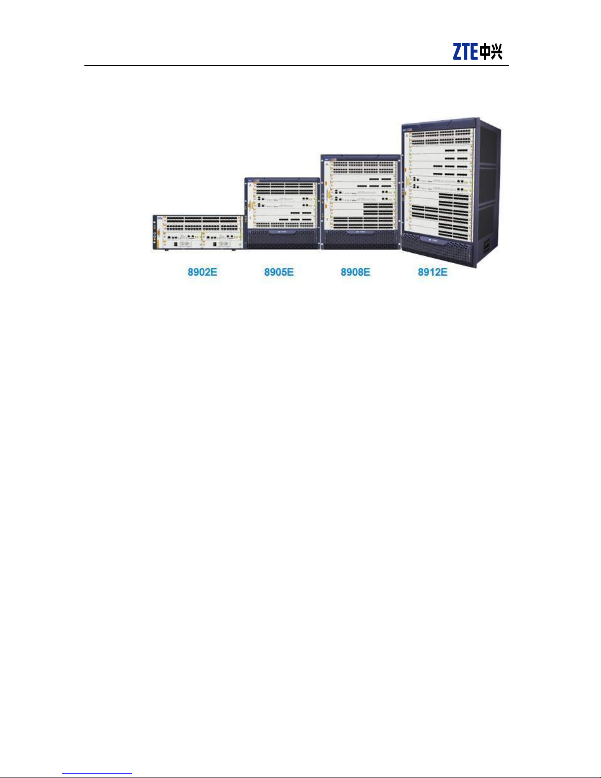
ZXR10 8900E series include Z XR10 8912E, ZXR10 8908E, ZXR10 8905 E and ZXR10
8902E, which have 1 2, 8, 5 and 2 s ervice slots respective ly. They have high-integration
interface boards and a wide variety of service f unctions. Their appearance is shown in
Figure 1-1.
ZXR10 8900E series Core Switch Product Description
2
© 2013ZTE CORPORATION. All rights reserved.
ZTE Confidential Proprietary
Figure 1-1 ZXR10 8900E series product appearance

ZXR10 8900E series Core Switch Product Description
ZTE Confidential Proprietary
© 2013 ZTE CORPORATION. All rights reserved.
3
2 Highlights
2.1 Super Big capacity/ High Densi ty Interfaces
With distributed modular design, non-blocking switching architecture, brand new
big-bandwidth fabric, ZXR10 8900E is an advanced core switch in the industry.
Each single slot of ZXR10 8900E c an pro vide m aximally 48* 10GE interfac es or 8*40G E
interfaces. In the future 8900E will be able to be smoothly upgraded to provide 100G
interfaces.
2.2 VSC Construc t Solid Cloud C ore
ZXR10 8900E supports Virtual Switch Clustering (VSC), which means the virtualization of
multiple physical switches into one logical switch. VSC enhances cluster system capacity
and port density, while at the same time simplifies simple topology and eases
administration.
Multiple physical switches can be interconnected through the normal line cards. The
80KM interconnection capability makes it possible to implement remote IDC backup.
The bandwidth of th e V SC interc onnec tion can r each 320Gb ps, eliminating any possible
bottleneck in the VSC system.
The forwarding inside VSC system is optimized so that there will be least amount of traffic
passing between VSC members.
Switchover between master and slave in VSC system is really fast and the switchover will
not cause any service interruption.
2.3 Distribute d Modul e Opera ting S ystem ROS 5.0
ZXR10 8900E adopts ful l-distributed m odular des ign: each proc ess enjo ys its dedicate d
resources alone; the coordination between processes is efficient and secure.
Each line card has its own CPU, while the m ain-control card is equippe d with a more
powerful CPU. Distributed protocol processing helps promote the overall computing
efficiency.
The expansion of management interfaces is flexible. Currently ZXR10 8900E is
compatible with management interfaces Netconf.

ZXR10 8900E series Core Switch Product Description
4
© 2013ZTE CORPORATION. All rights reserved.
ZTE Confidential Proprietary
2.4 Multi-service Bearing Ca pabilities
ZXR10 8900E supports rich features, including full L2/L3 features, multicast, MPLS L2/L3
VPN, etc.
ZXR10 8900E supports complete L2/L3 multicast technologies, including administratively
scoped multicast, MVR, IGMP Snooping, Filtering, Proxy, Fast Leave, IGMP,PIM-DM/SM,
PIM-SSM, DVMRP and MSDP. All these features help Enterprise user to deploy
multicast applications such as video conferencing and video surveillances.
2.5 Comprehensive IP v6 Features
ZXR10 8900E supports comprehensive IP v6 features, to f acilitate the migratio n to IPv6
network. For exam ple, ZXR10 8900E supports all b asic IPv6 featur es such as ICMPv6,
ND, SNMPv6, RADIUSv6; It also supports IPv6 routing protocols such as OSPFv3,
IS-ISv6, BGP4 +, PIM-SM for IPv6, MLD snooping; M ultiple tunnel t echnologies are also
supported including 6to4 tunnel, ISATAP tunnel, 6PE, etc.
2.6 Multi-Dimensional Securi ty & Reliability
Mechanism Guarante es Ever-online Services
Security/Reliabilit y related designs in ZXR10 8 900E fall into five categor ies, which
are secure architec tur e, s e c ure management and cont r ol, sec ur e op erati ng system,
secure calculation and reliable service.
Secure architecture: Redundant backup design has been put in place for the
forwarding control engines. Fast active/standby switchover is supported. Redundant
power supp ly module, fan module and clock module combined to m ake the swit ch
more robust. What’s more, ZXR10 8900E supports intelligent inspection, control,
warning and hot-swappable components.
Secure management an d control: Independent control, m onitoring and forwarding
planes guarantee superior equipment stability.
Secure operating system: ZXR10 8900E supports modular service, intelligent
function modules
Secure processing: Based upon multi-core CPU, ZXR10 8900E implements
multi-thread parallel high-performance processing to guarantee seamless
collaboration of multiple modules.
Reliable services: ZXR10 8900E supports multiple kinds of redundancy/backup
mechanisms including ZESR intelligent Ethernet smart ring, VRRP, LACP, FRR,
NSF and BFD. Service reliability can be well guaranteed.

ZXR10 8900E series Core Switch Product Description
ZTE Confidential Proprietary
© 2013 ZTE CORPORATION. All rights reserved.
5
2.7 Environment-friendly Inno vations
ZXR10 8900E supports multiple environmental-friendly innovations, including
centralized power manage ment, 5 level intelligent f an speed adjustment. A ll these
environmental friendly designs help cut the power consumption.
ZXR10 8900E supports d ying gasp, in case th ere is a power f ailure, 8 900E c an st ill
send out an alarm to the network OAM center, to inform about the reason of the
network break down. In th is way, the tim e to do the trouble-shooting on these kinds
of events could be minimized.

ZXR10 8900E series Core Switch Product Description
6
© 2013ZTE CORPORATION. All rights reserved.
ZTE Confidential Proprietary
3 Function introduction
3.1 L2 function
3.1.1 Basic Ethern et featu r es
3.1.1.1 MAC address management
As all forwarding tables of ZXR10 8900E are closely associated w ith MAC addresses,
MAC management is t he most basic and most im portant module of Ethernet sw itch. It
can maintain MAC address learning and synchronization and complete the following
management function:
MAC address binding: Bind specific MAC address to switc h port. After bind ing, do
not dynamic learn M AC, w hich wi ll lim it us er physical locatio n and pr ot ec t important
MAC address.
MAC address filtering: Afte r receiving the packets from source or destinati on MAC
address to specific MAC a ddress, the switch discard some pack ets to filter some
undesired users.
MAC address num ber limit: Limit MAC address number of some ports to control
user number of som e por ts, and pr eve nt s ystem resour ces of runnin g o ut whe n the
ports suffer from DOS attack.
MAC address freeze: Free ze some im portant ph ysical ports in s table net work, e.g.,
address of uplink port, so as to avoid network disconnection caused by the
infringement of key MAC address.
MAC address multi-angle display: Display and count VLAN table according to
VLAN, port, static an d dynamic aspects, prov ide network diagnosis, and maintain
network operation.
3.1.1.2 Port mirroring
Port mirroring can aut omatically copy the tr affic of one port to th e port so that network
administrator mak es real-time anal ysis on port traf fic when he jud ges network issues. It
provides network administrator with a monitoring means. For ZXR10 8900E, any port can
be configured to mirroring port; the ports at different rate can mirror to each other;
many-to-one, one-to-many and many-to-many port mirroring can also be done. The
equipment supports cross-card port mirroring, and simultaneous mirroring of several

ZXR10 8900E series Core Switch Product Description
ZTE Confidential Proprietary
© 2013 ZTE CORPORATION. All rights reserved.
7
mirroring group. It su pports port-based m irroring as well as flo w-based and ACL-based
one-to-many, many-to-one, and many-to-many mirroring.
ZXR10 8900E can perform port mirroring in the same equipment, and remote port
mirroring in RSPAN and ERSP AN. For RSP AN, mir roring port and m irrored port m ay be
in different switches . In s om e cases, m onitoring equipm ent and s witch ar e ph ysically far
away from each other, so a remote span technology is needed f or monitoring. RSPAN
monitoring principle is: set RSPAN source port at source switch, configure remote VLAN,
and send it out via Reflector port to reach destination switch via intermediate switch;
configure destination port at destination switch t o reach remote monitoring d estination.
ERSPAN (Encapsulated Remote SPAN), another remote port mirroring technology,
adopts GRE tunnel to encapsulate service stream of source port and transport it to
remote destination switch port. In the mirroring mode, data stream can fulfill the mirroring
across L3 interface, and ordinary SPAN a nd RSPAN can on ly fulfill the m irroring acr oss
L2 network.
3.1.1.3 Port security and protection
ZXR10 8900E supports port traffic control, broadcast storm suppression, whether to
allow jumbo fram e to pass, and rate negotiation to effective ly control por t data traffic,
avoiding network blocking and ensuring normal operation of network services.
ZXR10 8900E can anal yze line diagnosis, check whether line and line c onnection are
normal, and accurately locate line fault.
ZXR10 8900E can set som e or all port to loop check, and not check by default. The
function can check user or switch loop of port connection to process the port so as to
avoid switch broadcast storm and limit the effect to a certain port.
ZXR10 8900E supports VLAN-based loop check. The loop check can be perf ormed in
PVID VLAN or user-specified VLAN. One port supports the loop check of at most 8
VLANs at the same time.
The implementation pr incip le of port loop ch eck is that the por t s ends L2 m ulticas t ever y
15 seconds; if there is a l oop at a por t, L2 m ulticast pac k et is returned t o th e port, t hus it
can be judged that the loop is available.
3.1.2 VLAN and relative features
VLAN protocol, a basic pro tocol of L2 s witching equ ipm ent, enables the adm inistrator to
divide one physical LAN into several VLAN. Each VLAN has one VLAN ID which uniquely
identifies the VLAN. Se veral VLANs s hare the s witching eq uipment an d links of physical
LAN.

ZXR10 8900E series Core Switch Product Description
8
© 2013ZTE CORPORATION. All rights reserved.
ZTE Confidential Proprietary
Each VLAN is logically like one indep endent LAN. All fram e traff ic in one VLAN is lim ited
to the VLAN. Cross-VLAN access is made through L3 forwarding which will improve
network performance and reduce the entire traffic in physical LAN.
VLAN reduces network broadcast stor m and increas es network security and c entralized
management control.
ZXR10 8900E supports 802.1Q VLAN. The untagged pac ket can be added with VL AN
tag based on subnet, protocol and port to support a wide variety of VLAN features.
According to 802.1Q V LA N prot oco l, 12-bit VLAN is li mit to 4096 in number , whi c h af f ec t
some actual applications. 8900E has four extension modes: QinQ, PVLAN, VLAN
translation, and L3-related Super VLAN.
3.1.2.1 PVLAN
Private VLAN is a mechani sm that provides additional Layer 2 tr affic isolation between
ports within a regular VLAN. This feature places constrains on traffic flow between
specific ports in a VLAN. For instance, in an enterprise network, client ports can
communicate with server ports, but not among each other.
Private VLAN is port based and it can be enabled through PVLAN_ENABLE field in
PORT_TABLE for each port. There are three types of private VLAN ports:
Promiscuous port—a promiscuous port can communicate with all interfaces,
including the community and isolated ports within a private VLAN.
Isolated port—an isolated p ort has c om plete Layer 2 s eparatio n fr om all other por ts
within the same private VLAN except for the promiscuous ports. Private VLANs
block all traffic to isolated ports except traffic from promiscuous ports. Traffic
received from an isolated port is forwarded only to promiscuous ports.
Community port—Comm unity ports communicate among themselves and with the
promiscuous ports. These interfaces are isolated at Layer 2 from all other interfaces
in other communities or isolated ports within their private VLAN.
PVLAN can effectivel y ensure the communic ation security of network data. The user is
connected only to his default gateway. Without several VLAN and IP subnets, one
PVLAN can provide the connection with L2 data communic ation security. All users can
access PVLAN to connect default gateway without any access to other users in the
PVLAN. PVLAN ensure th at the ports in one VLA N do not communicate with e ach other,
but the services ca n go through T runk port. T hus, the users in one VLAN will not aff ect
each other because of service broadcast.
PVLAN does not need protocol message. It can be statically configure in ZXR10 8900E.

ZXR10 8900E series Core Switch Product Description
ZTE Confidential Proprietary
© 2013 ZTE CORPORATION. All rights reserved.
9
3.1.2.2 VL AN Translation
VLAN translation is an extension of VLAN function. If a port of the switch starts VLAN
translation, the data stream fr om the port m us t be tagg ed pac k et. VLAN tr anslat ion us es
PORT plus VLAN ID in tagged packet as the index to search in MAC – VLAN table and
get a new VID, then the traffic is switc hed in the new VLAN to translate data fr om one
VLAN to the other.
VLAN translation does not need protocol message. It can be statically configure in
ZXR10 8900E. It sho uld be noticed that if VLAN translation is started, VLAN c annot be
divided based on MAC address; if VLAN is divided based on MAC address, VLAN
translation cannot be started.
In addition single tag co nversion, 8900E us es VLAN translation and SVLAN to f ulfill the
following functions:
1. If the incoming packet is single tagged, be able to add outer tag according to policy,
and modify outer tag’s 8 02.1P value according t o inner tag’s 1P value, sup porting
policy-based mapping or one-to-one mapping;
2. If the incoming packet is single tagged, be able to modify inner tag and add outer tag
according to policy, and modify inner and outer tag’s 1P value according to incoming
tag’s 1P value, supporting polic y-based mapping or one-to-one mapping;
3. If the incoming pac ket is double tagged, be able to delete outer tag according t o
policy;
4. If the incoming pack et is double tagged, be able to delete outer tag, a nd modify
inner tag according to policy, and modify 1P value of the ne w inner tag ac c ord ing to
outer tag 1P value, supporting policy-based mapping or one-to-one mapping;
5. If the incoming pack et is double tagged, be able to m odify outer tag according to
policy, and modify 1P value of the new outer tag based on 1P value of the incoming
outer tag, supporting policy-based mapping or one-to-one mapping;
6. If the incoming pack et is double tagged, be abl e to modify inner tag accord ing to
policy, and modify 1P value of the new inner tag based on 1P value of the outer tag,
supporting policy-based mapping or one-to-one mapping;
7. If the incoming packet is double tagged, be able to modify inner and outer tag
according to policy, and modify 1P values of the new inner and outer tags according
to 1P value of the incoming outer tag, supporting policy-based mapping or
one-to-one mapping.
8. If the incoming packet is untagged, be able to add in ner and outer tag accord ing to
policy at one time.

ZXR10 8900E series Core Switch Product Description
10
© 2013ZTE CORPORATION. All rights reserved.
ZTE Confidential Proprietary
3.1.2.3 Super VLAN
Super VLAN can mak e the hosts, which are in the sam e physical switching equipment
but in different virtual broadcast domains, to locate in one IPv4 subnet and use one
default gateway. In one large-scale switching LAN, the mechanism has several
advantages over the traditional IPv4 addressing system. The biggest advantage is to
save address space occupanc y in IPv4 system.
Super VLAN and sub VLAN can be used to divide VLAN again. One or several sub
VLANs belong to one Super VLAN and use its default gateway IP address, namely,
aggregate several sub VLANs into one Super VLAN and use the same IP subnet an d
default gateway.
Super VLAN is a software f unc tio n. Et hern et A SIC c hi p is t rans pare nt to th e f unc tion a nd
switches data according t o software module VLAN s etting. Super VLAN does no t need
protocol message. It can be statically configure in ZXR10 8900E.
3.1.2.4 QinQ
QinQ with the m ultilayer VLAN tag stack, refers to tunnel protocol based on 802.1 Q
encapsulation. The core idea is to encapsulate private network VLAN tag to public
network VLAN tag; the message with double-layer tag goes through backbone network to
offer the user with a simple L2 VPN tunnel. Q inQ, a simple and manageable protocol,
does not need protocol message. It can be statically configure in ZXR10 8900E. It is
applied to converge nce-layer switch which can us e QinQ (with double tags) to increase
VLAN number in metro network.
In ZXR10 8900E sof tware s ystem , QinQ s oftwar e fun ctional m odul e sta ticall y conf igures
QinQ, and then correctly set the chip. QinQ VLAN consists of the following types:
SVLAN (Service VLAN): The VLAN defined in backbone network;
CVLAN (Customers VLAN): User-defined VLAN.
QinQ software functional module adds an attribute to the VLAN table. The attribute
indicates that the VLAN is SV LAN or CVLAN, and drive interface func tion at the lower
layer to set the QinQ function of the interface.
Ordinary QinQ only adds one outer t ag to the datagram of a port, which greatly limits
networking flexibilit y. For the flow received fr om one port, SVLAN (Se lective VLAN) can
selectively add different outer tag based on different inner tag according to user
demands.
With Selective VLAN, service providers can use a unique VLAN (called a service-provider
VLAN ID, or SP-VLAN ID) to support custom ers who have m ultiple VLANs, which offers
the multipoint-to-multipoint virtual LAN transparent transport and a simple L2 VPN tunnel.
Customer VLAN IDs (CE-VLAN IDs) are preserved and traffic from different customers is

ZXR10 8900E series Core Switch Product Description
ZTE Confidential Proprietary
© 2013 ZTE CORPORATION. All rights reserved.
11
segregated within the service-provider infrastructure even when they appear to be on the
same VLAN. Selective VLAN expand the VLAN space by using a VLAN-in-VLAN
hierarchy. The VLAN number can extend to 4094*4094. Another layer of 802.1Q tag
(SP-VLAN ID) is added to the 802.1Q-tagged (CE-VLAN ID) packets that enter the
service-provider network.
Some service stream s require SVLAN also sup ports the transparent tr ansport of VLAN
service that the pack et passes the switch without any interferenc e, namely, the number
and value of the tags remain unchanged.
SVLAN can work with VL A N trans la tio n to f lexib l y pro c es s both inner and out er t ags . For
details, refer to the cha pter “VLAN trans lation”. In ad dition, SVLAN c an fulfill the 802.1P
CoS priority mapping of outer tag and inner tag.
ZXR10 8900E supports traditional SVLAN configuration and VFP-based SVLAN
configuration. The latter can add the tags based on traffic type.
3.1.3 Link aggregation
Link aggregation means that physical links with the same transport medium and transport
rate are bound and logically look like a link. Link aggregation greatly increases the
bandwidth of peer physical links between switches or between switch and server.
Therefore, it is an important technology to increase link bandwidth and create link
transmission resilience and redundancy. Link aggregation can create
several-multiple-gigabit connection in GE, and logic link with faster transport in FE.
Meanwhile, link aggr egation has good protection. W hen a fault occurs, the traffic in the
trouble links will s witch quickly to norm al links of the aggregat ion. Link aggregati on can
increase the bandwidth and share traffic load.
ZXR10 8900E supports static and dynamic link aggregation of FE, GE, and 10G ports as
well as cross-card and cr oss-equipm ent link aggregation. Logic port from ZXR10 8900E
link aggregation is called smart group which can work as ordinary port.
3.1.3.1 St at i c aggregation
Static Trunk can manuall y add several ph ysical ports into T runk group to f orm one logic
port, but it is difficult to observe the status of link aggregation port.
ZXR10 8900E configur es link aggregation f unctions according to the following princ iple
which is also applied to LACP:
128 Trunk groups can be configured, and each Trunk group includes at most 8
member ports.
Support cross-interfac e board aggregation. Member ports ma y be in any interface
board, but the selected por t must work in the full-duplex mode, and working rates
must be consistent.

ZXR10 8900E series Core Switch Product Description
12
© 2013ZTE CORPORATION. All rights reserved.
ZTE Confidential Proprietary
Member port may adopt the access, trunk or hybrid mode, which must be
consistent.
3.1.3.2 LACP
LACP (Link Aggregation Control Protocol) follows IEEE 802.3ad. LACP dynamic
aggregates several physical ports to Trunk group for one smart group port. LACP
automatically aggregates to obtain the maximum bandwidth. LACP supports static
aggregation and d ynamic aggregati on. Static LAC P aggregatio n is manuall y configured,
and dynamic LACP aggregation dynamically adds the port to aggregation group.
ZXR10 8900E supports smart group parameter configuration, and share traffic load
according to the following modes (It can also be applied to static aggregation).
Source MAC address, VLAN, Ethernet type, and ingress port;
Destination MAC address, VLAN, Ethernet type, and ingress port;
Source and destination MAC address , VL AN, Eth er net type, and ingr es s port;
Source IP address, source TCP or UDP port;
Destination IP address, destination TCP or UDP port;
Source and destination IP address, and source and destination TCP or UDP port.
8900E also supports g lobal m ode, nam ely, share th e load in one sm art-group according
to the parameters of protocol messages of IPv4, IPv6, MPLS L2 VPN and MPLS L3 VPN
to distribute the traffic equably in the smart-group.
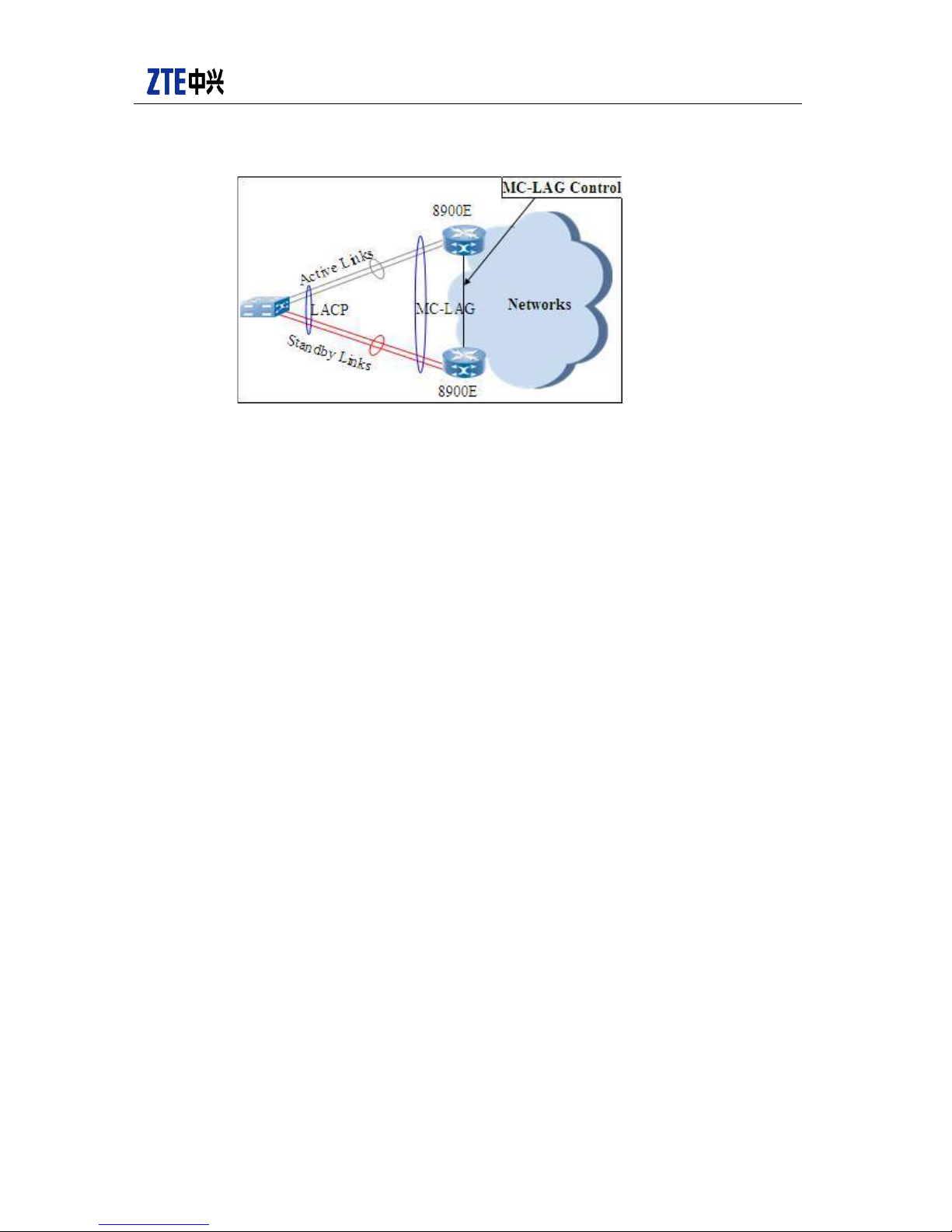
3.1.3.3 MC-ELAM
8900E support inter-card and intra-card link aggregation as well as MC-ELAM
(Multi-Chassis Ethernet Link Aggregation Manager) whose working principle is shown
as follows:
ZXR10 8900E series Core Switch Product Description
ZTE Confidential Proprietary
© 2013 ZTE CORPORATION. All rights reserved.
13
Figure 3-1 MC-ELAM structure
Normally, only half of the l i nk s fr om CE to PE1 an d P E2 are ag gr ega ted s uc ces s f ully. As
shown in the above figure, the successfully aggregated link from CE to PE1 is active link;
the non-aggregated link from CE to PE2 is standby link; data str eam is forwarded via
active link. W hen active aggregation equipment P E1 goes wrong, PE2 will re lease the
MC-ELAM control protocol signal of PE1 to proc ess the LACP for warding between P E2
and CE. When active equipment or active aggregation equipment returns to normal,
MC-ELAM control protocol will recover the forwarding process. MC-ELAM can access the
dual-uplink access network to increase network redundancy.
3.1.4 Spanning tree
3.1.4.1 STP
STP detects and clears the loop between L2 switching functional units, and provides
redundancy link to improve LAN performance and reliability.
STP module has the following major functions:
Avoid network loop, prevent LAN broadcast storm, and offer redundant path.
Detect topology change and reconfigure STP topology accordingly.
After the switch in one s ubnet executes STP algorithm, one ST P dynamic topology is
formed. The topolog y prevents the loop be tween any two work stations in LAN t o avoid
LAN broadcast storm . Meanwhile, STP algor ithm monitors topolog y change, create t he
new spanning tree after the change, and reco nfigure spanning tree topology wi th fault
tolerance. The switch m aintains and up dates M AC route t able acc ording to the status of
STP dynamic topology, and finally gains the MAC-layer route.
STP algorithm aim s to enable the s witch to d ynamicall y discover a n o-loop subs et (tree)
in topology and assure adequat e connectivity so that a path is available betwee n every
two LAN if the physical conditions allows. According to the principle in the figure, any line

ZXR10 8900E series Core Switch Product Description
14
© 2013ZTE CORPORATION. All rights reserved.
ZTE Confidential Proprietary
including node and conn ection node has one spanning tree which has good destinat ion
connectivity and can avoid network cycling. Therefore, spanning tree algorithm and
protocol can avoid network loop in any dynamic topology and clear the loop between any
two stations.
As IEEE802.1s-defined MSTP is compatible with existing IEEE802.1w-defined RSTP
and IEEE802.1D-defined or din ary STP, STP software module is only required t o suppor t
MSTP. When started, M STP can forcedly work as RSTP or STP to su pport STP and
RSTP mixed networking. And it can start STP in aggregation link and support port-based
enabling STP protocol.
ZXR10 8900E supports STP, RSTP and MSTP, and their mixed networking.
3.1.4.2 RSTP
RSTP (Rapid Spanning Tree Protocol), th e STP upgrade vers ion, follows IE EE 802.1w.
RSTP provide the fast port switching mechanism and shorten network convergence time.
RSTP has the following defects:
The entire switching netw ork has only one spanning tree. Lar ge network has slow
convergence and network topology change will have a great effect.
IEEE 802.1q is the switch connecti on stand ard protoc ol. In symm etrical connec tion
(in VLAN, the connected ports between switches has the same trunk), one spanning
tree has no influence on data forwarding between switches. However, in the
asymmetrical connection, the connected ports between switches are blocked by
RSTP, which will affect the connectiv it y and waste the band wid th.
3.1.4.3 MSTP
MSTP (Multiple-instance Spanning Tree Protocol), developed based on STP/RSTP,
follows IEEE 802.1s. MST P divides switching networ ks into several zones , and several
STP instances run in one zone. VLAN is translated to instance in M: 1 mode (bind several
VLANs to one instance) , th us eac h VLAN is tr ansfor med into a tr ee networ k to av oid the
loop.
MSTP has the following advantages:
In single VLAN, STP supports rapid convergence.
As MSTP structure spanning tree through VLAN and does not block inter-switch
connection port, the load will be shared.
M: 1 mapping reduces switch resource utilization rate.
MSTP is compatible with STP/RSTP to make network deployment simpler.

ZXR10 8900E series Core Switch Product Description
ZTE Confidential Proprietary
© 2013 ZTE CORPORATION. All rights reserved.
15
3.1.5 L2 multicast
After the router forwards multicast traffic, in the network, Ethernet switch forwards
multicast traffic to multicast user. Traditional switch usually broadcasts the multicast
traffic , which wastes network bandwidth, cause broadcast storm and affect normal
service. Therefore the switch needs to support L2 multicast so as to join and leave
multicast group according to multicast user status and dynamically maintain multicast
group.
3.1.5.1 I GM P Snoooping
ZXR10 8900E supports the L2 multicast technology IGMP Snooping to manage multicast
group members, suppres s L2 network multicas t flooding, an d prevent un authoriz ed user
from receiving multicast traffic. By snooping IGMP message in the communication
between user and router, IGMP Snooping maintains the correspondence relation
between multicast ad dress and VLAN correspondence table . It maps the members of
one multicast group to o ne VL AN, a nd forwards the rec eived multicast packet onl y to the
VLAN members of the multicast group. IGMP Snooping and IGMP protocol are both used
for multicast group managem ent and control, and bot h employ IGMP m essage. What is
different is that IGMP pr otocol runs on net work layer and IGMP Snoop ing on link la yer.
When the switch receives I GMP message, IGMP Snoopi ng analyzes the information of
IGMP message and create and maintain L2 MAC multicast address table.
When ZXR10 8900E starts IGMP Snooping, multicast m essage performs L2 multicast;
when 8900E does not start IG MP Snooping, multic ast message perform s L2 broadcast.
8900E also support MLDv1/v2 snooping for smooth transition from IPv4 to IPv6.
3.1.5.2 IGMP Proxy
In some network topologies, IGMP proxy technology does not run multicast route
protocol, but learns the multicast member and makes simple multicast forwarding
according to the register ed f or multicast distribution. IGMP pr oxy suppor ts host interface
and router interface. Host interface (also known as uplink interface) points to root node of
distribution tree, n amely, uplink to multicas t router. The interface runs the host function
rather than IGMP. When receiving IGMP query packet, host interface sends IGMP
member report. Multicas t joining or leavi ng packet is sent to t he connected rou ter when
member database chan ges. Host inter face also forwards the rec eived multicast packet
according to member database. Router interfac e (downlink interfac e) deviates from root
node and downlinks to user host. The interface runs IGMP protocol to register, query and
delete downlink user group members. It rec eives member reports, creates and modifies
one member form, sends query packet, queries whether the host le aves its group, and
uplinks and downlinks the forwarded and received multicast packet according to the
registered multicast member database.
IGMP Proxy and IGMP Snooping have the same function but different mechanism:
IGMP Snooping looks into IGMP message to get re lative information, and IGMP Prox y
ZXR10 8900E series Core Switch Product Description
16
© 2013ZTE CORPORATION. All rights reserved.
ZTE Confidential Proprietary
intercepts and processes IGMP request of terminal user and then forwards it to
upper-level router.
3.1.6 L2PT
In QinQ VPN mode, if VPN uses locating at different places want to initiate their L2
protocol f or exam ple, STP, LACP, ZD P, the y need to use cor e network to trans fer these
L2 protocol messages tr ansparently, and these m essages with preser ved MAC address
for bridge cannot process transparent transmission normally. L2PT (layer 2 protocol
transportation) solves this problem, so it is widely used to transfer user network L2
protocol message in QinQ VPN.
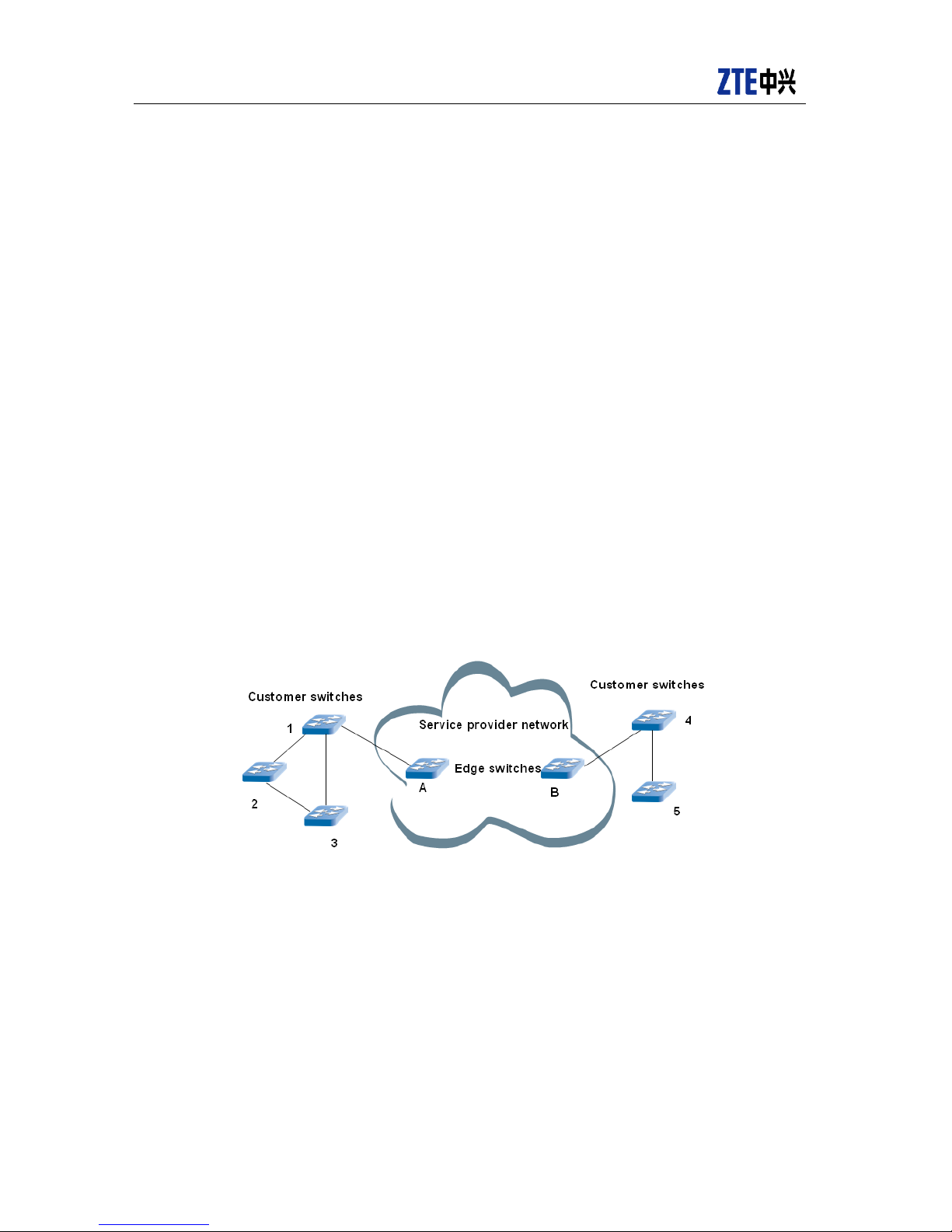
L2PT networking is as shown in the following figure.
Edge Switches: It locating at the edge of operator network connects customer
network equipment.
Layer 2 protocol transportation port: On port of Edge Switch. The enc apsulation of
L2 protocol message.
Transportation PDU: Encapsulated prot ocol message, for exam ple ZDP, STP and
LACP, etc.
Figure 3-2 L2TP Networking
On the port without initiated L2PT, L2 protocol messages (STP,ZDP,LACP)instead
of being forwarded is either discarded or sent up for protocol processing, which will cause
several blocked stp dom ains in customer network as per different locations, so that the
entire customer VPN cannot run an integrated STP topology. L2PT transfer BPDU
message transparently in VPN, which helps customers to supply the gap.
The received L2 protocol messages will be encapsulated at the transportation port of
edge switch, then broadca st the encapsulated messages . Initiate remote transportation
switch port to encapsulate these messages.

ZXR10 8900E series Core Switch Product Description
ZTE Confidential Proprietary
© 2013 ZTE CORPORATION. All rights reserved.
17
The message encapsulation and de-capsulation can be done by changing message MAC
address.
3.2 L3 function
3.2.1 IPv4 route protocol
3.2.1.1 RIP
RIP protocol is based on the vector distance routing algorithm of local network. It
employs UDP packet to switch RIP route information, and the protocol packet to be
transported is encapsulated into UDP packet. The route information in RIP message
includes the number of the nodes on the route, namely, hop number. Route node decides
the route to destination networks according to the hop number. RFC requires that the hop
number is not more than 16, which is applied to internal gateway in small-scale
autonomous system.
ZXR10 8900E RIP has the following functions:
Transmit and receive RIP message according to the protocol, check message
correctness and verify its identification.
Support RIPV1/V2, plain text authentication and MD5 authentication, and route
reallocation.
Route loop generatio n and route con vergence acceler ation adopt sp lit-horizon and
trigger updates technology.
Support protocol DEBUG.
3.2.1.2 OSPF
OSPF is the IET F-developed internal gate way protocol (IGP) based on link status and
SPF algorithm. OSPF can converge routing table in a short time, and prevent loop, which
is vital to mesh networks or different LANs connected via several bridges. Each
equipment running OSPF maintains one unified database describing autonomous system
topology structure. The database includes such information as partial status of each
equipment, e.g., available interfaces and neighbors, connected network status and
external route of autonom ous system. OSPF uses link status algorithm to c alculate the
shortest path from eac h ar ea to a ll des t ina tio ns . When the equipment w orks or any route
changes, the equipment configured with OSPF diffuses LSA to all equipments in one
area. LSA includes link status and ne ighbor association information of the equipment.
The information from LSA forms link status database. All equipments in the area use one
specific database to describe topology structure in the area.

ZXR10 8900E series Core Switch Product Description
18
© 2013ZTE CORPORATION. All rights reserved.
ZTE Confidential Proprietary
ZXR10 8900E OSPF has the following functions:
Adopt layered network topology structure which is suitable for enormous
interconnected network.
Use dynamic route algorithm. Route calculation adopts Dijiksra algorithm to
automatically follow network topology structure change at a quick rate;
Support display and configuration command from primary console as well as
SNMP-related command, display and MIB variable.
Support route protoc ol packet authe ntication, includin g simple password validation
and MD5 authentication, and prevent route protocol packet from illegal modification.
Adopt the retransmission and confirmation mechanism to assure the reliability of link
status synchronization.
Support different distance measurement solutions, e.g., physical distance, delay,
throughput, etc.
Support STUB AREA and NSSA functions.
Support domain boundary and autonomous system boundary router.
Support classless route and route aggregation.
Use Route-Map to control route reallocation and filtering.
3.2.1.3 IS-IS
IS-IS route protocol, the representation of router OSI model, is used for TCP/IP-based IP
network. It can easi ly perform the extens ion, mainly IPv6. IS-IS system c onsists of two
layers: backbone layer ( L2) and area layer (L1). One router is in only one area. L1 router
only knows the topology in its area. All traffic to other areas is sent to the near est L2
router. L2 router must form the backbone, similar to OSPF backbone area 0.
ZXR10 8900E IS-IS protocol has the following functions::
Support L1 and L2 address aggregation.
Support L1 and L2 hierarchical routes and ATT identity.
Support 3-area address and smooth area address migration.
Support load balance to one destination.
Support plain text authentication of interface and area.

ZXR10 8900E series Core Switch Product Description
ZTE Confidential Proprietary
© 2013 ZTE CORPORATION. All rights reserved.
19
3.2.1.4 BGP
BGP, an external gateway protocol, switches no-loop route information between
autonomous systems. The information has many attributes to create autonomous system
topology, carry out route policy based on autonomous system. The path reachable
information with autonomous system sequence attribute can clear route loop.
Autonomous system is the collection of routers and terminals which locate in one
management control domain, are treated as single entity, and control route table
extension through BGP classless inter-domain routing. BGP-4 also introduces the
mechanism to support route aggregation, including AS path aggregation. BGP is
designed to use autonomous system to provide one structural view of Internet. The
Internet is divided into several autonom ous systems to create one large network which
composed of small, eas ily m anageable net works. T hese small ne tworks adopt their ow n
rules and management policies.
ZXR10 8900E BGP has the following functions:
Suitable for enormous networks, e.g., backbone network.
Support EBGP and IBGP.
Support EBGP multi-hop technology.
Support group attributes and route reflector.
Support AS ally and route turbulence suppression.
Support MP-BGP;
Support MD5 authentication and route filtering;
Support route reallocation.
3.2.1.5 Policy routing
Traditional routing policy performs route forwarding according to the route table
generated by routing proto col or static route. However , in some applications, the users
have some special req uirements for routing. T raditional routing polic y can only perform
forwarding by destinat ion address. This indiscriminating f orwarding mechanism cannot
meet the requirements of increasingly complicated network services.
Compared with traditional routing, policy routing provides more flexible message
forwarding and route control capability. The network m anagement users can not only
perform route forwarding by destination address but also can select other forwarding
paths according to protocol type, message size, application, IP source address and other
conditions. Policy-based routing is more beneficial for network traffic distribution and QoS
improvement. Polic y routing means to match certain feature values in IP data packet
according to the policy set by the network management user. Those that match the

ZXR10 8900E series Core Switch Product Description
20
© 2013ZTE CORPORATION. All rights reserved.
ZTE Confidential Proprietary
condition are forwarde d according to the route spec ified by the policy; those t hat fail to
match are forwarded according to traditional route table.
ZXR10 8900E series realizes ACL-based policy routing.
In addition to policy ro uting, ZXR10 8900E series also provides policy routing backup
function.
The switch uses Redirec t comm and to realize policy routi ng function b ased on A CL. For
one ACL rule, the route can only be redirected to a next-hop address. When this next-hop
address has any problem, the corresponding policy routing will also fail. When the switch
has multiple egresses, policy routing backup (PBR BACKUP) function can be realized by
configuring Redirect to multiple next-hop addresses, so that when the active link is faulty,
the route can be automatically switched to the backup next-hop ad dr ess .
3.2.2 Ipv6 Routing
ZXR10 8900E supports the following IPv6 unicast route features:
Support IPv6 neighbor discovery protocol, which realizes the functions of router and
prefix discovery, address resolution, next-hop address determination, neighbor
unreachable test and repeated address test and which can better support the
mobility of nodes.
Support IPv6 path MTU discovery protocol, which can discover the maximum
transmission unit of the path so as to make sure the message size sent by the node
does not exceed the MTU value of the path.
Support IPv6 static route.
Support IPv6-based dynamic routing protocols RIPng, OSPFv3, ISISv6 and BGP4+.
3.2.3 IPv4/IPv6 Transition
ZXR10 8900E provides a num ber of transitional mechanisms for conversion from Ipv4
network to Ipv6 network, including double stack technology and various tunnel
technologies that are applicable to different environments:
Support IPv4/IPv6 do uble protocol stack . Double stack technolog y can completel y
solve the coexistence problem of IPv4/IPv6, but is only effective when the
equipment in the whole network supports double stack. Therefore, it has high
requirement for IPv4 network reform. It should be noted that the double stack
technology is the foundation of all the tunnel mechanisms below.
Support manually configured IPv6 tunnel. Manual tunnel technology is simple,
mature and stable, but has high management overhead and poor expandability. It is
 Loading...