

Zte NCN 2001-EPI/CE, NCN 2111E-EPI/BE, NCN 2211E-EPI/BE, NCN 2201-EPI/CE, NCN 2002-EPI/CE User Manual
...
NCN 2XXX-EP(B)(C)
Brick IP Camera
User Manual
ZTE Netview
4/F,W1-A,Bldg,Gaoxin S.1th Ave.,,
Hi-Tech Industrial Park,
Nanshan District, Shenzhen
P. R. China
518057
Tel: (86) 755 26525680-2503/400-8866755
Fax: (86) 755 26520574
URL: http://www.ztenv.com.cn
E-mail: wang.guofu@zte.com.cn
0049001000@zte.com.cn

LEGAL INFORMATION
Copyright © 2012 ZTE NETVIEW.
The contents of this document are protected by copyright laws and international
treaties. Any reproduction or distribution of this document or any portion of this
document, in any form by any means, without the prior written consent of ZTE
NETVIEW is prohibited. Additiona lly, the contents of this d ocument are protected by
contractual confidentiality obligations.
All company, brand and product names are trade or service marks, or registered trade
or service marks, of ZTE NETVIEW or of their respective owners.
This document is provided “a s is”, and all express, implied, or sta tutory warranties,
representations or condi tions are disclaimed, including withou t limitation any implied
warranty of merchantability, fitness for a particular purpose, title or non-infringement.
ZTE NETVI EW and its licensors shall not be liable for damages resulting from the use of
or reliance on the information contained herein.
ZTE NETVIEW or its licensors may have current or pending intellectual property rights
or applications covering the subject matter of this document. Except as expressly
provided in any written license between ZTE NETVIEW and its licensee, the user of this
document shall not acquire any lic e nse to the subject matter herein.
The contents of this document and all policies of ZTE NETVIEW, including without
limitation policies related to support or training are subject to cha nge without notice.
Revision History
Date Revision
No.
Serial No. Description
2012/06/21 R1.0 Version upgrade

ZTE NETVIEW
Values Your Comments & Suggestions!
Your opinion is of great value and will help us improve the quality of our product
documentation and offer better serv ic e s to our cus tomer s .
Please fill out the following questionnaire and fax to:
Please fax to (86) 755 26520574 or mail to ZTE Netview, 4/F,W1-A,Bldg,Gaoxin
S.1th Ave., Hi-Tech I ndustrial Park, Nanshan D istrict, Shenzhen, P. R. China
518057.
Thank you for your cooperation!

Your Comments & Suggestions
Document
Name
NCN 2XXX-EP(B)(C) Brick IP Camera User Manual
Product
Version
Document
Revision Number
R1.0
Equipment Installation Date
Your
evaluation of
this
document
Presentation:
(Introductions, Procedures, Illustrations, Completeness, Level of Detail, Organization,
Appearance)
Good Fair Average Poor Bad N/A
Accessibility:
(Contents, Index, Headings, Numbering, Glossary)
Good Fair Average Poor Bad N/A
Intelligibility:
(Language, Vocabulary, Readability & Clarity, Technical Accuracy, Content)
Good Fair Average Poor Bad N/A
Your
suggestions
for
improvement
of this
document
Please check the suggestions which you feel can improve this
documentation:
Improve the overview/introduction Make it more concise/brief
Improve the Contents Add more step-by-step procedures
Improve the organization Add more troubl eshoot i ng in f ormati on
Include more fi gures Make it less technical
Add more examples Add more/better quick reference aids
Add more detail Improve the index
Other suggestions
____________________________________________________________________
____________________________________________________________________
____________________________________________________________________
____________________________________________________________________
____________________________________________________________________
# Please feel free to write any comments on an attached sheet.
If you wish to be contacted regarding your comments, please complete the following:
Name Company
Postcode Address
Telephone E-mail

Contents
About this Manual .................................................................. i
Purpos e of th is Man ual ....................................................................... i
Typograph ical C onven tions ................................................................. i
Mouse O pera tion C onven tion s ........................................................... iii
Safety Signs .................................................................................... iv
Chapter 1 .............................................................................. 1
Product Overview ................................................................. 1
Introduction .................................................................................... 1
Main Features .................................................................................. 1
Basic .......................................................................................................... 1
Audio/Video Processing ................................................................................ 2
Remote Tran spo rtati on/A ccess ..................................................................... 2
Appearan ce and Dimen sions ............................................................. 3
Network ing D iagr am ........................................................................ 7
Chapter 2 .............................................................................. 9
Installation ........................................................................... 9
Precautions ..................................................................................... 9
Power and Grounding Requirements ............................................................. 9
Tools, Instruments and Documents ............................................................ 10
Install ation Meth od .......................................................................... 10
Wall Mounting ........................................................................................... 10
Ceiling Mounting ....................................................................................... 11
Preparat ion of Connec ting C ables ..................................................... 12

Preparation of Network Cable ..................................................................... 12
Preparation of RS232 Connecting Cable ....................................................... 14
Cabling .......................................................................................... 15
Cablin g Requi rem ents ................................................................................ 15
Protection Ground Cable ............................................................................. 16
Audio Ou tput Cable .................................................................................... 16
Audio Input Cable ...................................................................................... 17
Video Ca ble ............................................................................................... 17
Communication Cable ................................................................................ 18
RS422 Cable ............................................................................................. 19
Digital Quantity Collection Cable ................................................................. 19
Fiber Ca ble ................................................................................................ 20
Label Preparat ion ....................................................................................... 20
Chapter 3 ............................................................................ 23
Configuration and operation .............................................. 23
Configu rati on F low .......................................................................... 23
Login steps ............................................................................................... 24
Handling if Unable to Login ......................................................................... 26
Configuration .................................................................................. 28
IP Address Setting ..................................................................................... 28
PPPOE Dial Setting ..................................................................................... 31
Login and Restart the Camera Device .......................................................... 32
Setting Manage Host .................................................................................. 33
Setting Device ID ...................................................................................... 34
Setting Serial Parameter ............................................................................ 35
Configuring I/O ......................................................................................... 36
Operation ....................................................................................... 37
Viewing Video ............................................................................................ 37
PTZ Control ............................................................................................... 39
Video Qu ery .............................................................................................. 39

Preset P osition Setting ............................................................................... 42
Encoding Parameter Settings ..................................................................... 44
OSD Setting .............................................................................................. 45
Hide Area Setting ...................................................................................... 47
Storage Task Setting ................................................................................. 48
Video Loss Detection Setting ...................................................................... 51
Hide Detect Set ting ................................................................................... 52
Motion Detection Setting ............................................................................ 53
Alarm Application ...................................................................................... 54
System Managemen t ...................................................................... 56
Self-Diagnosis ........................................................................................... 57
Storage Medium Management .................................................................... 59
Time S ynch roniza tion ................................................................................ 60
User Management ..................................................................................... 60
Log Query ................................................................................................ 63
Device U pgrade .............................................................................. 64
Chapter 4 ............................................................................ 67
Routine Maintenance .......................................................... 67
Maintenance Test ............................................................................ 67
Preventive Maintenance ................................................................... 67
Safety Protection............................................................................. 67
Troubleshooting .............................................................................. 68
Appendix A .......................................................................... 71
Packing, Storage and Transportation ................................. 71
Packaging....................................................................................... 71
Transportation ................................................................................ 71
Storage .......................................................................................... 72
Appendix B .......................................................................... 73

Abbreviations ..................................................................... 73
Appendix C ......................................................................... 74
Connect into ZXVNMS Platform.......................................... 74
Creating E ncode r and C amer a on Mana gemen t Clien t ........................ 74
Write ZXVNMS Information into the Camera ..................................... 82
Appendix D ......................................................................... 87
Specification ....................................................................... 87

This page is intentionally blank.

Confidential and Proprietary Information of ZTE NETVIEW i
About this Manual
Purpose of this Manual
This guide provides the basic information about main functions, structure,
installation, operation, routine maintenance, package, transportation and
storage of NCN 2XXX-EP(B)(C) brick IP cameras.
This manual applies to these models of brick IP cameras: NCN 2101-EPI/CE,
NCN 2201-EPI/CE, NCN 2001-EPI/CE, NCN 2111E-EPI/BE, NCN 2211E-EPI/BE,
NCN 2002-EPI/CE, NCN 2102-EPI/CE, NCN 2202-EPI/BE, NCN 2003-EPI/CE,
NCN 2103-EPI/CE, NCN 2203-EPI/BE, and NCN 2205-EP/BE. Please mak e sure
the model is applicable before using this manua l.
Typographical Conven tions
ZTE docum ents employ the follow ing typograph ical conventions.
TABLE 1 TYPOGRAPHICAL CONVENTIONS
Typeface Meaning
Italics
References to other guides and documents; parameter values
“Quotes” Links on screens
Bold Menus , menu options, input fields , radio button names , check b oxes,
drop-down lists, dialog box names, w indow names
CAPS Keys on the keyboard and buttons on screens and company name
Constant
width
Text that you type, program code, files and directory names, and
function names
[ ] Optional parameters
{ }
Mandatory parameters
| Select one of the parameters that are delimited by it
Note: Provides additional informa tion about a certain topic

NCN 2XXX-EP(B)(C) Brick IP Camera User Manual
ii Confidential and Proprietary Info r m ation of ZTE NETVIEW
Typeface Meaning
Checkpoint: Indicates that a particular step needs to be checked
before proceeding further
Tip: Indicates a suggestion or hint to make things easier or more
productive for the reader

About This Manual
Confidential and Proprietary Information of ZTE NETVIEW iii
Mouse Operati on Convent ions
TABLE 2 MOUSE OPERATION CONVENTIONS
Typeface Meaning
Click Refers to clicking the primary mouse button (usually the left
mouse button) once.
Double-click Refers to quickly clicking the pr imary mouse button (usually the
left mouse button) twice.
Right-click Refers to clicking the secondary mouse button (usually the right
mouse button) once.
Drag Refers to pressing and holding a mouse button and moving the
mouse.
NCN 2XXX-EP(B)(C) Brick IP Camera User Manual
iv Confidential and Proprietary Info r m ation of ZTE NETVIEW
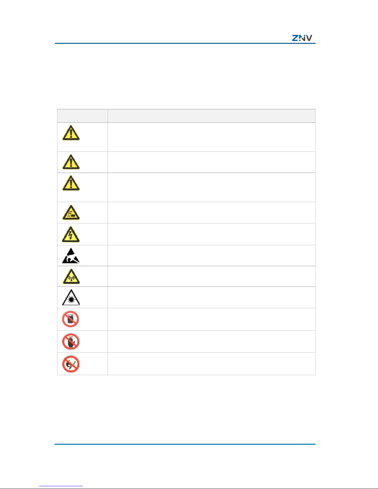
Safety Signs
TABLE 3 SAFETY SIGNS
Safety Signs Meaning
Danger: Indicates an imminently hazardous situation, which if not
avoided, will result in death or serious inj ury. This signal word should
be limited to only extreme situations.
Warning: Indicates a potentially hazardous situation, which if not
avoided, could result in death or serious injury.
Caution: Indicates a potentially hazardous situation, which if not
avoided, could result in minor or moderate injury. It may also be used
to alert against unsafe practices.
Erosion: Beware of erosion.
Electric shock: There is a r isk of electric shock.
Electrostatic: The device may be sensitive to static electricity.
Microwave: Beware of strong electromagnetic field.
Laser: Beware of strong laser beam.
No flammables: No flammables can be stored.
No touching: Do not touch.
No smoking: Smoking is forbidden.

Confidential and Proprietary Information of ZTE NETVIEW 1
Chapter 1
Product Overview
This cha pter int roduces th e model d escripti on, mai n features,
technical parameters and networking diagram of NCN
2XXX-EP(B)(C) brick IP camera s.
Introduction
Brick IP cam era is a kind of embedded digital monitor product
specially designed for remote video surveillance. It uses
audio/video compression/decompressing, TCP/IP network
technology, and with code burned in FLASH, makes it possible
for more stable running of the system.
Brick IP camera can be connected with other network
monitori ng equipments to form a powerful video survei llance
network. It can be widely applied to banks, telecommunications,
electric power, judicial procedure, transportation, residence,
factory, warehouse, resources, hydra ulic structure, and so on.
Main Features
Basic
PTZ control
RS485 or RS422 interface, support PTZ control and lens
adjustment, support multiple decoder protocols.
Heartbeat function

NCN 2XXX-EP(B)(C) Brick IP Camera User Manual
2 Confidential and Proprietary Information of ZTE NETVIEW
Through the heartbeat mechanism, the management and
control center can monitor the running status of IP cam era.
Alarm function
At least 1 channel of alarm input, 1 c hannel of alarm output,
motion detection and camera lens blocking alarm, and alarm
linkage
Voice talk function
Support two-way voice talk
User management
Multi-level user management, administrator and operator
have their own authority restriction, high safety coefficient.
Built-in WEB server, support IE visiting
Support local storage
Realize T-Flash card local storage
Audio/Video Processing
Support 1 channel o f PAL video s ignal and H.264 encoding so
that dual stream can be achieved, support variable frame rate
(up to 25 fps) and code rate (up to 2Mb/s ).
Support 4CIF, DCIF, 2CIF, CIF, and QCIF video format s.
Caption adder, date and time, English letter and Chinese
characters, etc. can be added on the screen.
Two-way voice talk, use G.711, AAC, and Speex audio
compression standard, field voice listening and remote
volume adjustment.
Remote Transportation/Access
Use 100M fibre interface
Chapter1 Product Overview
Confidential and Proprietary Information of ZTE NETVIEW 3
Use 10M/100M self-adaptive network port.
With NAT and auto reconnecting after network disconnected
Setting parameter via application software or IE browser,
real-time browsing video, viewing IP camera status, realize
alarm linkage.
Support remote downloading, achieve user software upgrade.
Formatting T-Flash card and resetting device.
Self-diagnosis, logs of alarm and exception events for
retrieving.
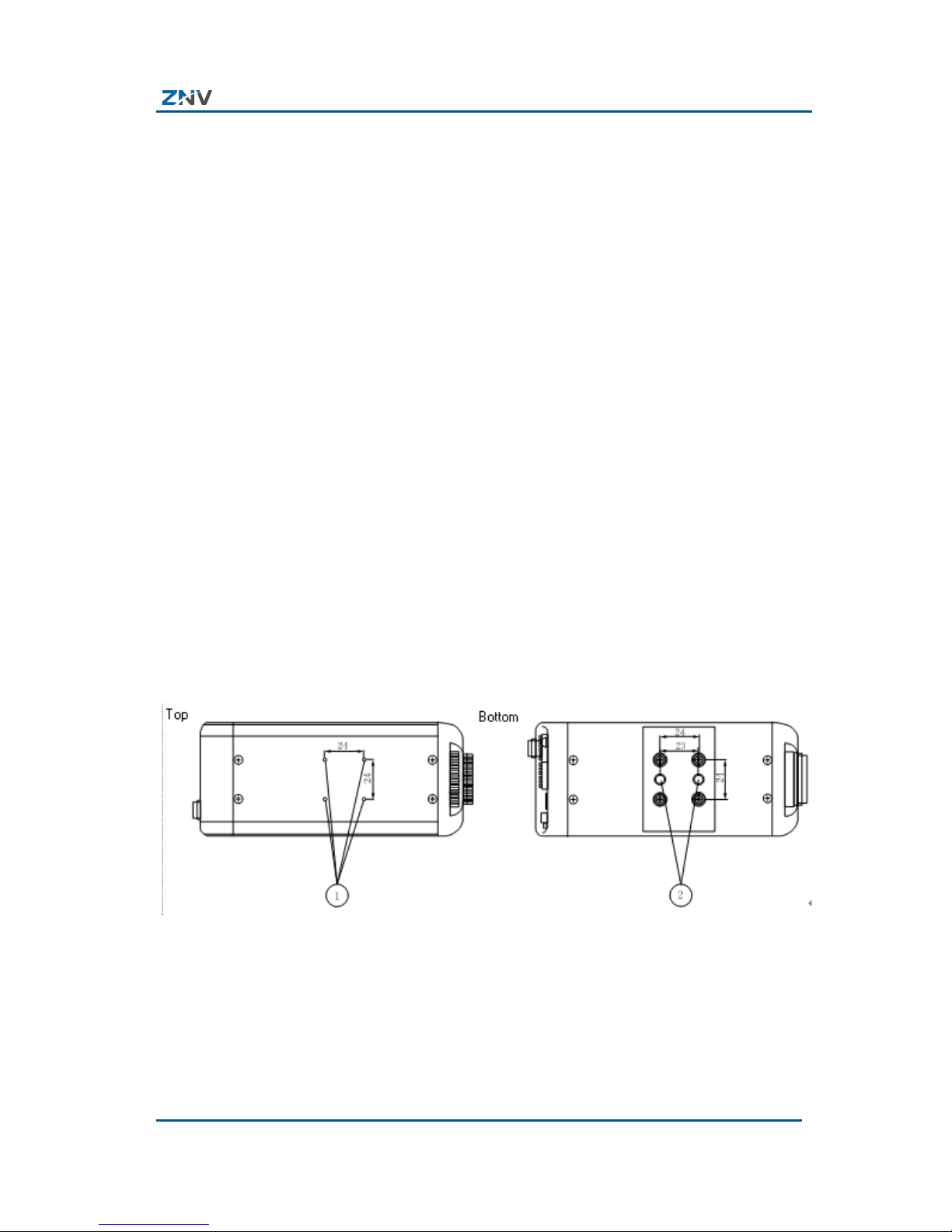
Appearance and Di mensions
The top and bottom view of NCN 2XXX-EP(B)(C) brick IP
camera is as shown in Figure 1, and front and side view of it is
as shown in Figure 2.
FIGURE 1 TOP AND BOTTOM VIEW OF NCN 2XXX-EP(B)(C) BRICK IP
CAMERA
NCN 2XXX-EP(B)(C) Brick IP Camera User Manual
4 Confidential and Proprietary Information of ZTE NETVIEW
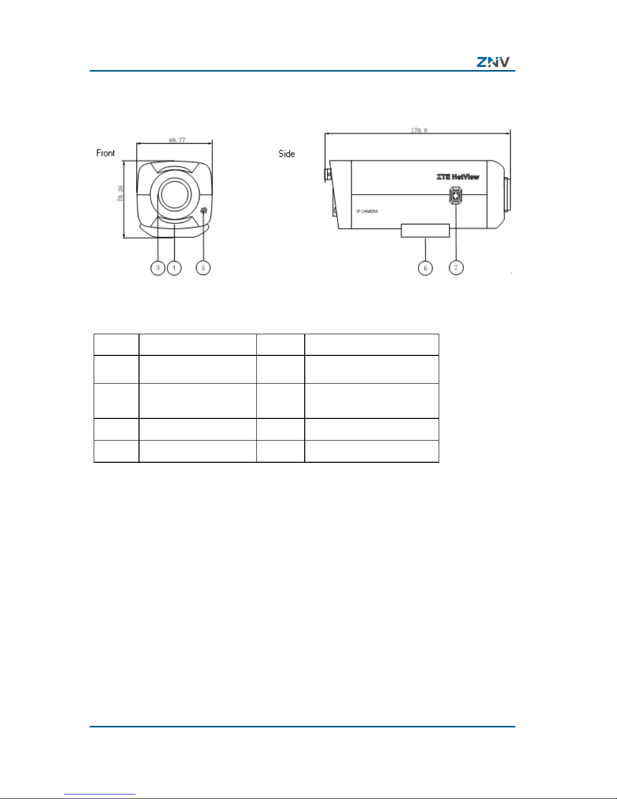
FIGURE 2 FRONT AND SIDE VIEW OF NCN 2XXX-EP(B)(C) BRICK IP
CAMERA
TABLE 4 DESCRIP TION ON THE FRONT AND SIDE VIEWS
No. Function No. Function
1 Mounting hole 2
U1/4〞20UNC
3 CS/C Lens mount 4
back focus length
adjusting ring
5 MIC 6 Mount set
7 ALC lens mount
The re ar pa nel view of the f ollow ing mod els of brick IP cameras
is as shown in Figure 3, and the description of the rear panel is
as listed in Table 5.
NCN 2001-EPI/CE, NCN 2111E-EPI/BE, NCN 2211E-EPI/BE,
NCN 2002-EPI/CE, NCN 2102-EPI/CE, NCN 2202-EPI/BE, NCN
2003-EPI/CE, NCN 2103-EPI/CE, NCN 2203-EPI/BE.
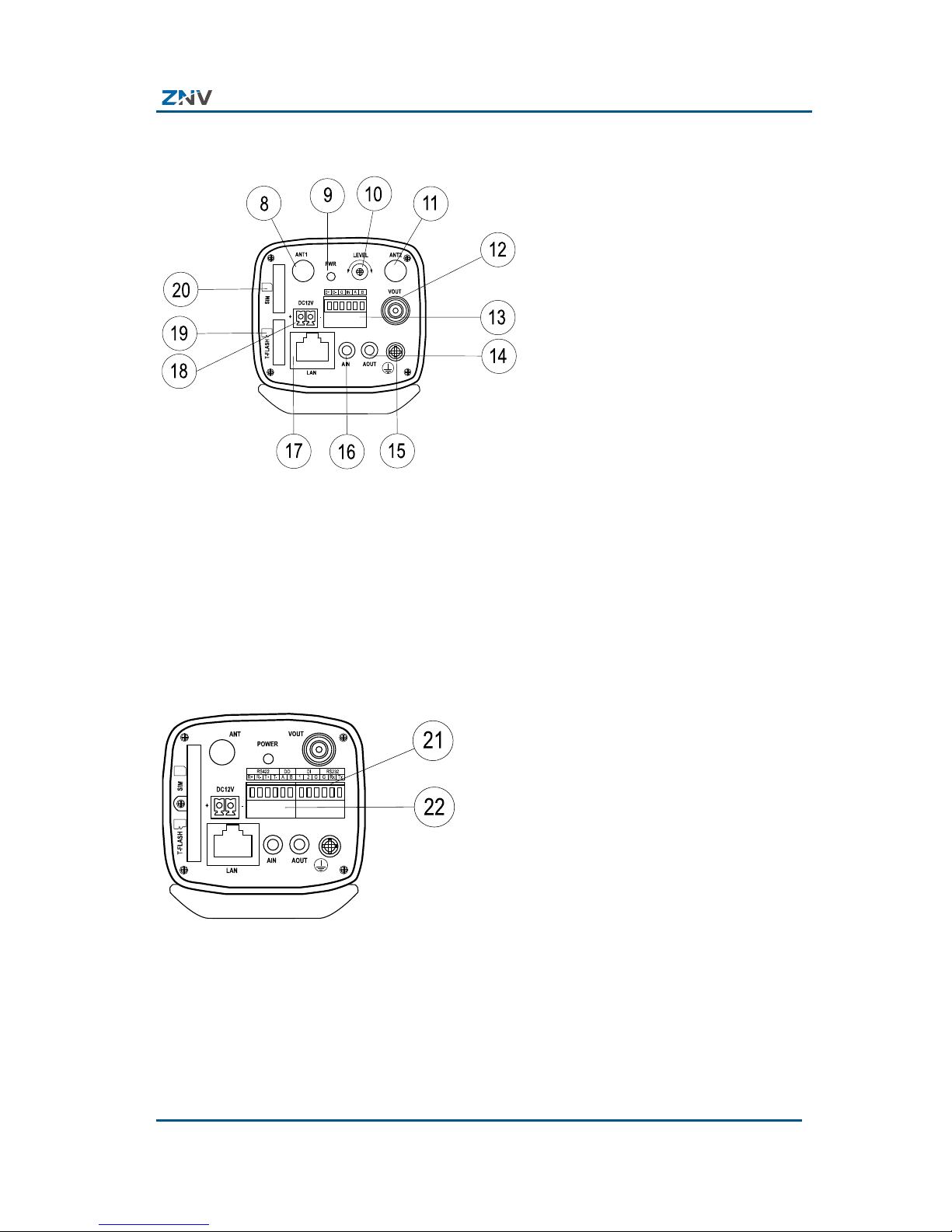
Chapter1 Product Overview
Confidential and Proprietary Information of ZTE NETVIEW 5
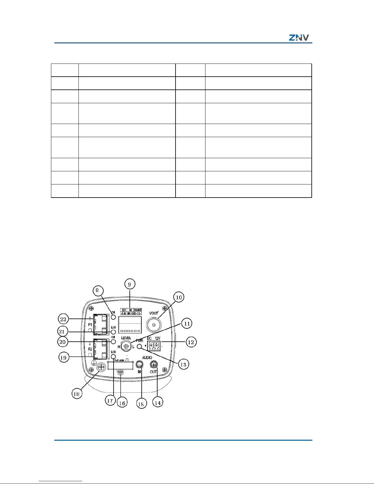
FIGURE 3 REAR PANEL VIEW OF NCN 2XXX-EP(B)(C) BRICK IP CAMERA
The rear panel view of the following models of brick IP cameras
is as shown in Figure 4, and the description of the rear panel is
as listed in Table 5.
NCN 2101-EPI/CE and NCN 2201-EPI/CE:
FIGURE 4 REAR PANEL VIEW OF NCN 2XXX-EP(B)(C) BRICK IP CAMERA
NCN 2XXX-EP(B)(C) Brick IP Camera User Manual
6 Confidential and Proprietary Information of ZTE NETVIEW
TABLE 5 DESCRIPTION OF INTERFACES ON REAR PANEL
No. Function No. Function
8 Antenna SMA interface 9 Power LED
10 Image brightness adjustment 11 Antenna SMA interface
12 VOUT analog composed video
output BNC connector
13 RS 422, DO, DI terminals
14
AOUT audio output interface
15
Grounding screw
16
AIN audio input interface
17
Network interface (RJ 45
connector)
18
12V power interface
19
T-Flash card socket
20
USIM card socket
21
RS 232, DI terminals
22
RS422, DO terminals
The rear panel of NCN 2205-EP/BE camera is as shown in Figure
5, and the description of the rear panel is as listed in Table 6.
FIGURE 5 REAR PANEL VIEW OF NCN 2205-EP/BE

Chapter1 Product Overview
Confidential and Proprietary Information of ZTE NETVIEW 7
TABLE 6 DESCRIP TION OF INTERFACES ON REAR PANEL OF NCN
2205-EP/BE
No. Function
No. Function
8 In-
position indicator of fiber
module 1
9 RS 485, DO, and DI terminals
10 BNC connector for VOUT analog
composite video output
11 Image brightness adjustment
12 12V power interface 13 Power indicator
14 AOUT audio output interface 15 AIN audio input interface
16 T-Flash card slot 17 Data transceiver indicator of fiber
module 2
18 Grounding screw 19 LC fiber interface 2
20 In-
position indicator of fiber
module 2
21 Data transceiver indicator of fiber
module 1
22 LC fiber interface 1
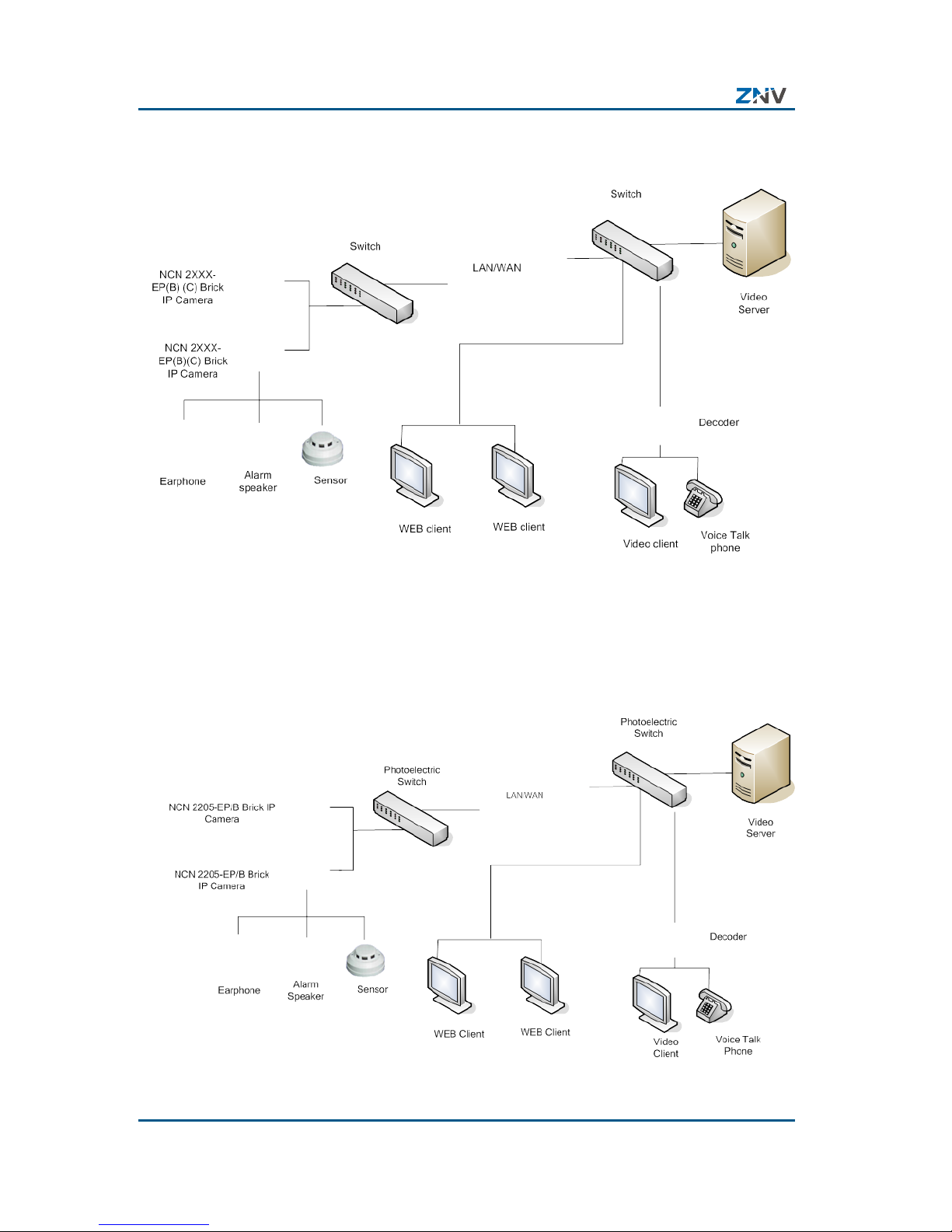
Networking Di agram
The typical networking diagram o f NCN 2XXX-EP(B)(C) brick IP
camera is as shown in Figure 6.
NCN 2XXX-EP(B)(C) Brick IP Camera User Manual
8 Confidential and Proprietary Information of ZTE NETVIEW
FIGURE 6 NETWORKING DIAGRAM OF NCN 2XXX-EP(B)(C) BRICK IP
CAMERA
The typical networking d iagram of NCN 2205-EP/B fiber brick IP
camera is as shown in Figure 7.
FIGURE 7 NETWORKING DIAGRAM OF NCN 2205-EP/B BRICK FIBER IP
CAMERA

Confidential and Proprietary Information of ZTE NETVIEW 9
Chapter 2
Installation
This chapter introduces the installation of NCN 2XXX-EP(B)(C)
brick IP camera, includin g in st a lla t ion pr e pa r at ion, preparation
of connecting cables, cabling requirement and installation
method.
Precautions
Please check complete articles against the packing list
carefully af t er unpacking.
Please read this chapter carefully before installation.
Please turn off the power of the device before you start
installation.
Please check the supply voltage to avoid device being
damaged due to unmatched voltage.
Do not use the device where it would be subject to extreme
temperature or humidity. Keep the device in a place with good
ventilat ion, and keep it away from liquid s plashing or violent
vibration.
If the device does not work normally, please contact your
dealer, instead of dismantling or repairing it. The company
will not be reliable for any damages resulted in unauthorized
repairing or maintenance.
Power and Grounding Requirements
Power requirement: DC12V±10%, 2.5A.

NCN 2XXX-EP(B)(C) Brick IP Camera User Manual
10 Confidential and Proprietary Information of Z TE NETVIEW
Grounding requirement: The case should have a protection
ground conne cted with the earth. The gro unding resistance of
the protection ground should be no more than 4 Ω.
Tools, Instruments and Documents
Prepare th e r equ i red en gi n eerin g d ocum ents an d u ser m anu al
for engineering. Before installation, please prepare the
following tools and instruments:
Minus s crew drive r, Multi meter, sci ssors, jaw vice, pe rcussion
drill, tape measure, marker pen, etc.
Accessories: indoor camera stand: 1pc, plastic/metal
expansion screw: 3pcs, tapping s crew: 3pcs.
Insta llation Method
NCN 2XXX-EP(B)(C) brick IP camera can be installed on wall or
ceiling. You can select a proper installation me thod according to
actual condition.
Wall Mounting
To install the device on wall, please follow these steps:
1. Unpack the camera and check if any appearance damage.
2. Install the bracket
i. For cemen t wall surface, expan sion screw s need to be
installed first. The location hol es for expansion screws
should be aligned with those on the bracket. Then insta ll
the bracket.
ii. For wooden wall surface, install the brac ket with tapping
screws directly.

Chapter2 Installation
Confidential and Proprietary Information of ZTE NETVIEW 11
Note:
The wall where you will mount the brick camera must be
strong enough to bear 3 tim es weight of the camera and its
accessories.
3. Install Camera
Rotate the camera into the bracket by using the mount set
at the top of the camera. Adjust the camera to proper place,
and then tighten the knob on the bracket to fix the camera.
Finally, mount the lens onto the camera. Please pay
attention to the selection of C or CS lens mount.
FIGURE 8 MO UNT ON WALL
Ceiling Mounting
To install the device on ceiling, please follow these steps:
1. Unpack the camera and check if any appearance damage.
2. Install the bracket;
i. For cemen t wall surface, expan sion screw s need to be
installed first. The location holes for expansi on screws
should be aligned with those on the bracket. Then insta ll
the bracket.
ii. For wooden wall surface, install the brac ket with tapping
screws directly. The wall where you will mount t he brick
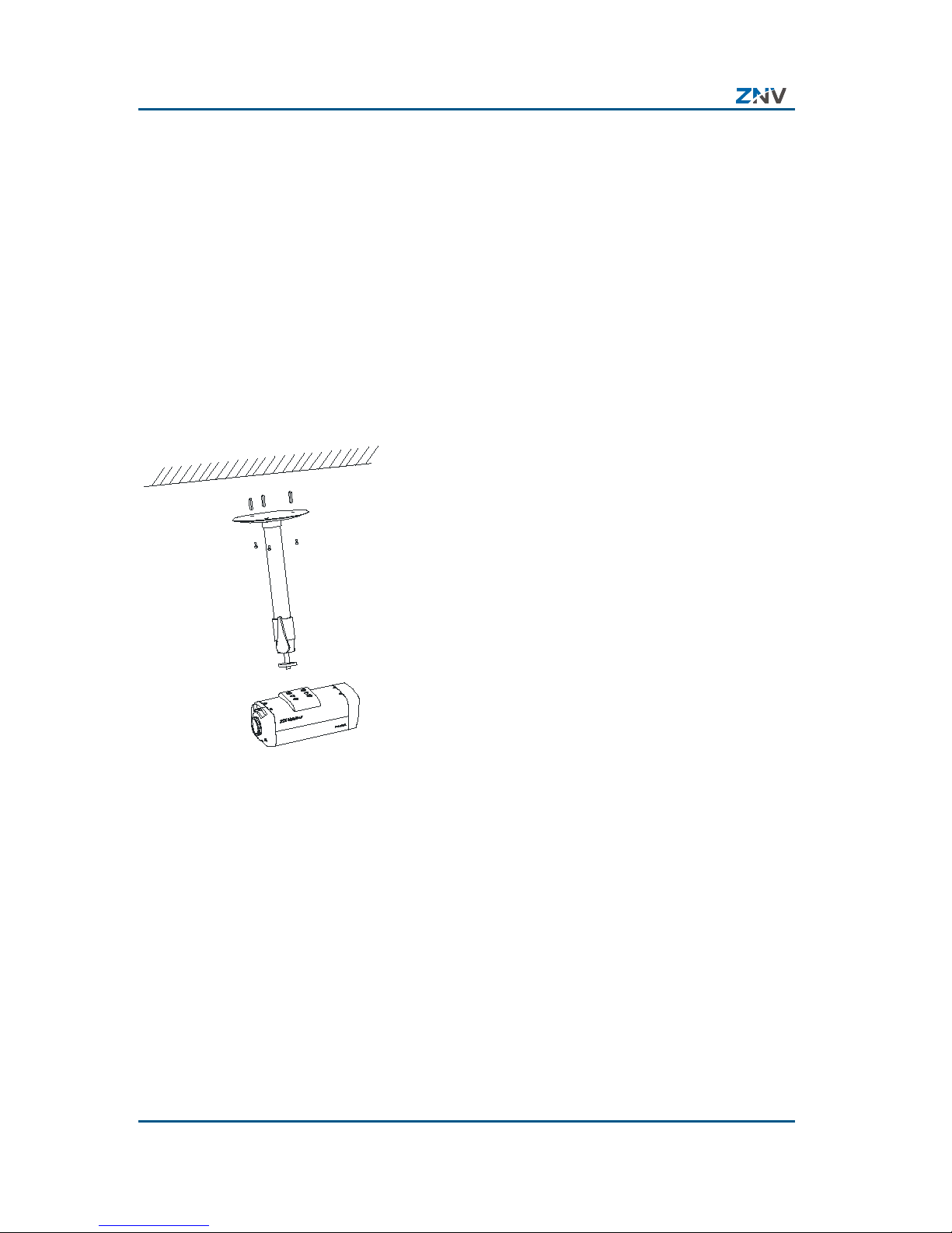
NCN 2XXX-EP(B)(C) Brick IP Camera User Manual
12 Confidential and Proprietary Information of Z TE NETVIEW
camera must be strong enough to be ar 3 times weight of
the camera and its accessories.
3. Install Camera
Rotate the camera into the br acke t by using the mo unt se t
at the top of the camera. Adjust the camera to proper place ,
and then tighten the kno b on the bracket to fix the camera.
Finally, mount the lens onto the camera. Please pay
attention to the selection of C or CS lens mount.
FIGURE 9 MO UNT ON CEILING
Preparation of Connect ing Cables
Preparation of Network Cable
The method of preparing network cable is as below:
1. Material and tool
One twisted pair cable (8 pins, the length can be defined as
to the actual demand, but must be within 100m), 2
standard RJ45 head, one RJ45crimping pliers.
2. Pin Definition

Chapter2 Installation
Confidential and Proprietary Information of ZTE NETVIEW 13
To make the network cable according to the actual
situation, there are two options:
i. Use the following method to make the network cable
when the NCN 2XXX-EP(B)(C) brick IP camera is
connected with network hub or switch, as shown in
Figure 10.
FIGURE 10 THE CORRESPONDING RELATIONSHIP OF THE STRAIGHT
THROUGH CABLE
1 White-orange
2 Orange
3 White-green
4 Blue
5 White-blue
6 Green
7 White-brown
8 Brown
White-orange 1
Orange 2
White-green 3
Blue 4
White-blue 5
Green 6
White-brown 7
Brown 8
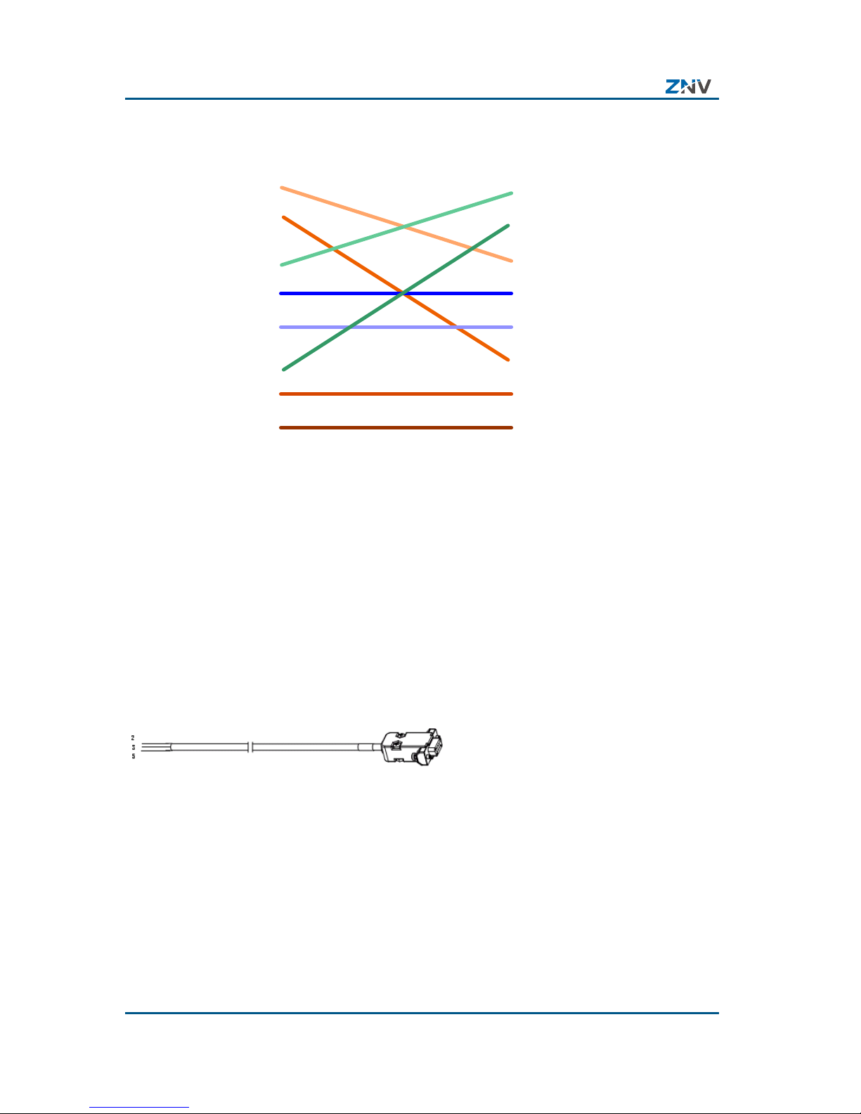
ii. Use the following method to make the crossover
network cable when NCN 2XXX-EP(B)(C) brick IP
camera is connected with client-end PC, as shown in
Figure 11.
NCN 2XXX-EP(B)(C) Brick IP Camera User Manual
14 Confidential and Proprietary Information of Z TE NETVIEW
FIGURE 11 THE CORRESPONDING RELATIONSHIP OF THE CROSSOVER
CABLE
1 White-orange
2 Orange
3 White-green
4 Blue
5 White-blue
6 Green
7 White-brown
8 Brown
White-green 1
Green 2
White-orange 3
Blue 4
White-blue 5
Orange 6
White-brown 7
Brown 8
Preparation of RS232 Connecting Cable
RS-232 connecting cable is required to be used when
connecting NCN 2XXX-EP(B)(C) brick IP camera with DTE
device with DB9 female connector (such as computer, alarm
equipment, access control ler, etc.). The cable i s as shown in
Figure 12.
FIGURE 12 RS-232 CONNECTING CABLE
The method of preparing RS-232 connecting cable is as below:
1. Material and tool
One twisted pair cable (8 pins), one DB9 female connector
2. Pin definition
To make the RJ45 connector according to the pin def initio n
in Table 7:

Chapter2 Installation
Confidential and Proprietary Information of ZTE NETVIEW 15
TABLE 7 PIN DEFINITION OF RJ45 CONNECTOR
Pin No. Name I/O Definition
1 RXD I Receive data
2 TXD O Transfer dat a
3 GND Ground
“I” means camera input, O means camera output.
Cabling
The extern al cables t o be connect ed involve DC power cabl e,
protection ground cab le, audio input cable, audio output cable,
video cable, straight though cable, communication cable and
digital quantity colle ct io n c a ble . During the on-site in sta lla tio n,
the cable connectors should be welded according to lengths of
the actually used external cables.
Cabling Requirements
1. The laid cables must be protected with sheaths, such as PVC
pipe, PVC troughs, metal tubes, serpentine pipes or
winding tubes.
2. The AC cab les and t he DC cab les must be lai d separatel y,
but DC cables can be laid together with signal cables , video
cables and network cables.
3. If there is the antistatic floor in the room, the cables should
be laid under the floor. If there is a cabling rack in the room,
the cables may be wired along the cabling rack. If neither
of them is available, the cables should be laid along the
wall foot or top.
4. If all the cables are laid on the cabling rack in the room,
observe the existing layout principle of customer. If the
original cable of customer is not added with the PVC tube
or trough, the tube and trough can be ignored generally.
NCN 2XXX-EP(B)(C) Brick IP Camera User Manual
16 Confidential and Proprietary Information of Z TE NETVIEW
Note: In layout of cables in conduits or troughs, do
not lay too many cables in it. Some 30% space
should be reserved.
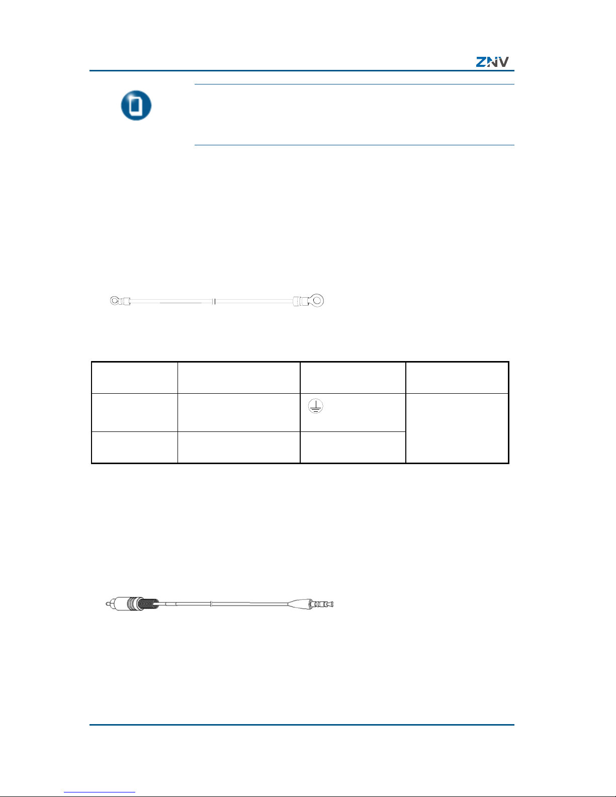
Protection Ground Cable
Connect chassis to protective grounding. The protective
grounding cable is a s shown in Figure 13 lists the wiring method
of the protective grounding cable.
FIGURE 13 PROTECTIVE GROUNDING CABLE DIAGRAM
A B
TABLE 8 WIRING LIST OF P ROTECTIVE GROUNDING CABLE
Connecting
End
To Where Connect to Remark
End A Brick IP Camera
grounding
screw
Number of cables:
1;
Length:
as per
configuration End B Grounding bar in the
equipment room
Grounding terminal
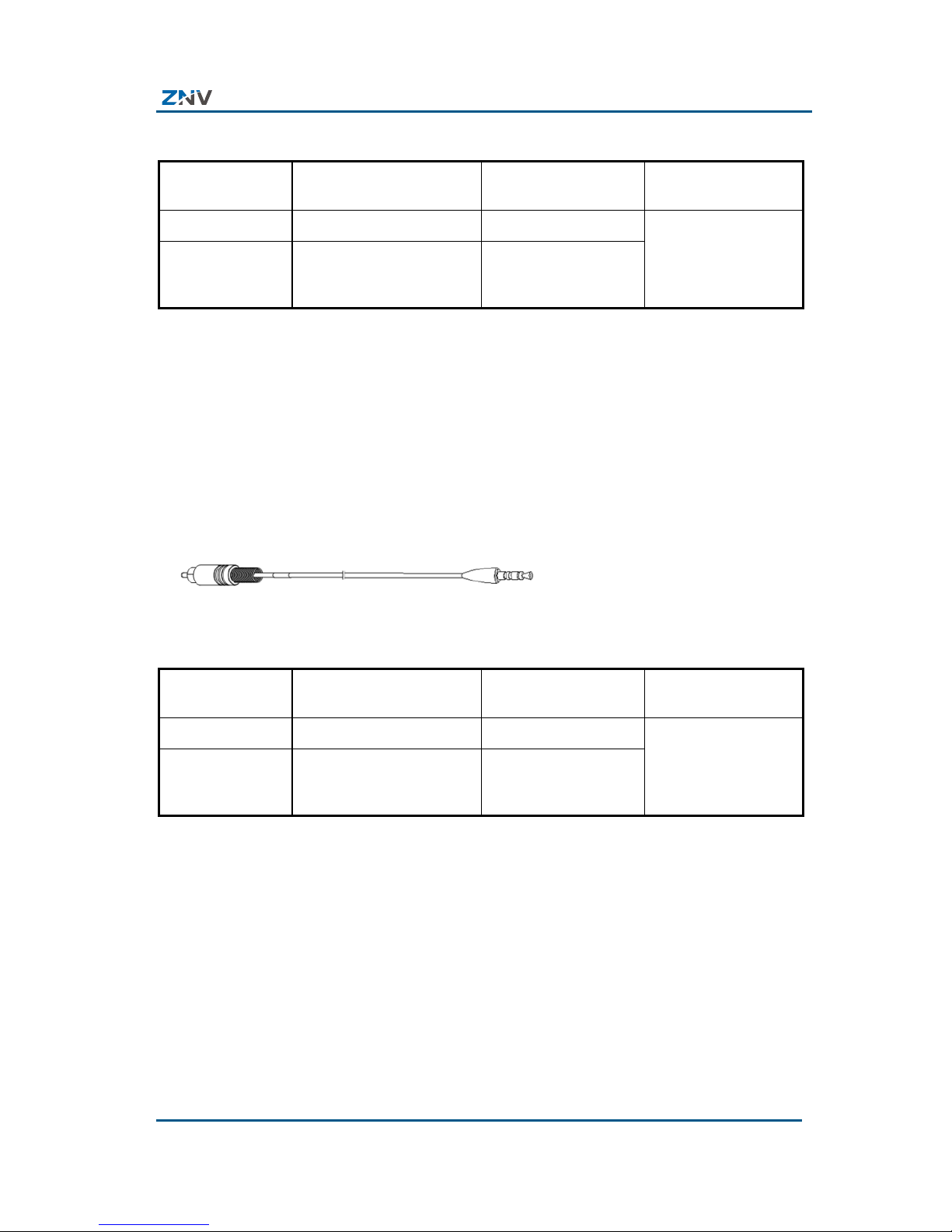
Audio Output Cable
Audio output cabl e is used t o output audio signal. It conne cts
with speaker. The audio output cable is as shown in Figure 14.
FIGURE 14 AUDIO O UTPUT C ABLE DIAGRAM
A B
Table 9 lists the wiring method of the audio output cable when
connecting to external speaker.
Chapter2 Installation
Confidential and Proprietary Information of ZTE NETVIEW 17
TABLE 9 WIRING LIST OF AUDIO OUTPUT CABLE
Connecting
End
To Where Connect to Remark
End A Speaker Mono (left / right ) Number of cables:
1;
Length: less than
3m
End B Rear panel of NCN
2XXX-EP(B)(C) brick
IP camera
AOUT
Audio Input Cable
Audio input cab le is used to input audio signal. It co nnects with
active micro phone or sound pickup. The audio output c able is as
shown in Fi gure 15. Ta ble 1 0 lists the wiring method of audio
input cable.
FIGURE 15 AUDIO INPUT CABLE DIAGRAM
A B
TABLE 10 WIRING LIST OF AUDIO I NPUT C ABLE
Connecting
End
To Where Connect to Remark
End A Microphone Audio output Number of cables:
1;
Length:
as per
configuration
End B Rear panel of NCN
2XXX-EP(B)(C) brick
IP camera
AIN
Video Cable
Video cable is used to transmit video input/output signal. The
video cable is as shown in Figure 16. Table 11 lists the
description of wiring method of the video cable. Select End A
connector according to the type of interface of the video
terminal device, and BNC connector for camera, and determine
the length of video cable as per co nfiguration.
 Loading...