

Page 1

ZXSDRR8854
MacroRadioRemoteUnit
HardwareInstallation
Version:1.0
ZTECORPORATION
No.55,Hi-techRoadSouth,ShenZhen,P .R.China
Postcode:518057
Tel:+86-755-26771900
Fax:+86-755-26770801
URL:http://support.zte.com.cn
E-mail:800@zte.com.cn
Page 2

LEGALINFORMATION
Copyright©2017ZTECORPORATION.
Thecontentsofthisdocumentareprotectedbycopyrightlawsandinternationaltreaties.Anyreproductionor
distributionofthisdocumentoranyportionofthisdocument,inanyformbyanymeans,withoutthepriorwritten
consentofZTECORPORATIONisprohibited.Additionally,thecontentsofthisdocumentareprotectedby
contractualcondentialityobligations.
Allcompany,brandandproductnamesaretradeorservicemarks,orregisteredtradeorservicemarks,ofZTE
CORPORATIONoroftheirrespectiveowners.
Thisdocumentisprovided“asis”,andallexpress,implied,orstatutorywarranties,representationsorconditions
aredisclaimed,includingwithoutlimitationanyimpliedwarrantyofmerchantability,tnessforaparticularpurpose,
titleornon-infringement.ZTECORPORATIONanditslicensorsshallnotbeliablefordamagesresultingfromthe
useoforrelianceontheinformationcontainedherein.
ZTECORPORA TIONoritslicensorsmayhavecurrentorpendingintellectualpropertyrightsorapplications
coveringthesubjectmatterofthisdocument.ExceptasexpresslyprovidedinanywrittenlicensebetweenZTE
CORPORATIONanditslicensee,theuserofthisdocumentshallnotacquireanylicensetothesubjectmatter
herein.
ZTECORPORA TIONreservestherighttoupgradeormaketechnicalchangetothisproductwithoutfurthernotice.
UsersmayvisittheZTEtechnicalsupportwebsitehttp://support.zte.com.cntoinquireforrelatedinformation.
TheultimaterighttointerpretthisproductresidesinZTECORPORATION.
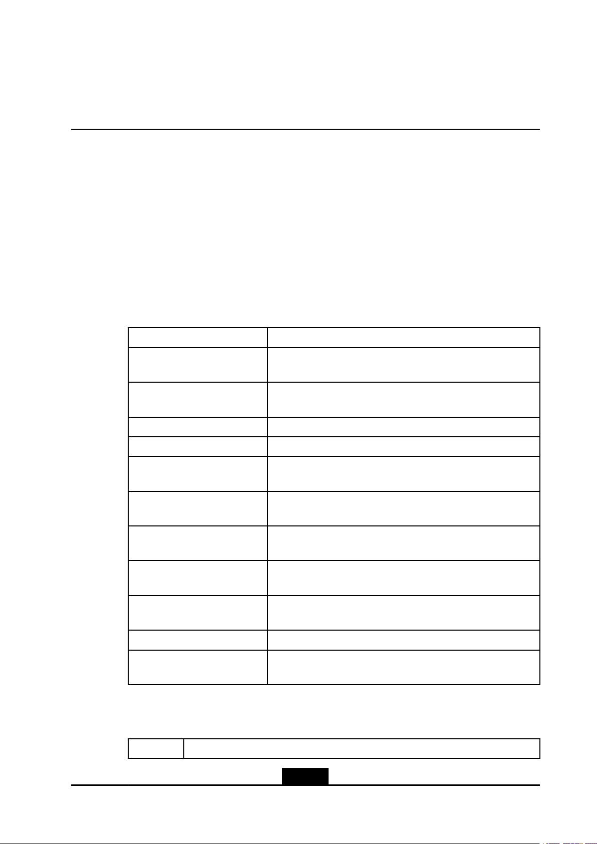
RevisionHistory
RevisionNo.RevisionDateRevisionReason
R1.32018–01–03lUpdatedthewaytobundletheRRUin2.2Precautionsfor
DeviceHoisting.
lUpdatedthefollowingsections:4RRUInstallation,4.1
InstallinganRRUonaWall,4.2InstallingaSingleRRUon
aPole,4.3InstallingTwoRRUsonaPole,4.5Installing
anRRUonaGantry ,4.6InstallinganRRUonaL-shape
Support.
lAddednewsection:4.4InstallingaSingleRRUinPole
Hoop-MountedMode.
R1.22016-07-30AddedscaldprotectioninformationinSection2.3Installation
Precautions
R1.12016-06-20lUpdated“5.2InstallingAntennaFeederCables”
lUpdated“5.5InstallingtheDCPowerInputCable”
lAdded“AppendixAInstallingtheDCJunctionBox”
R1.02016-04-06Firstedition
SerialNumber:SJ-20160405141455-003
PublishingDate:2018-01-03(R1.3)
SJ-20160405141455-003|2018-01-03(R1.3)ZTEProprietaryandCondential
Page 3

Contents
AboutThisManual.........................................................................................I
Chapter1InstallationFlow........................................................................1-1
Chapter2InstallationPreparations..........................................................
2.1PrecautionsforDeviceTransport.........................................................................2-1
2.2PrecautionsforDeviceHoisting...........................................................................
2.3InstallationPrecautions.......................................................................................2-4
2.4InstrumentsandMetersList................................................................................
2.5InstallationSpaceRequirement...........................................................................2-7
Chapter3UnpackingandInspection.......................................................3-1
Chapter4RRUInstallation........................................................................
4.1InstallinganRRUonaWall................................................................................4-5
4.2InstallingaSingleRRUonaPole.......................................................................4-11
4.3InstallingTwoRRUsonaPole..........................................................................4-17
4.4InstallingaSingleRRUinPoleHoop-MountedMode..........................................4-22
4.5InstallinganRRUonaGantry...........................................................................4-27
4.6InstallinganRRUonaL-shapeSupport............................................................4-32
Chapter5CableInstallation......................................................................
5.1InstallingtheProtectiveGroundingCable.............................................................5-3
2-1
2-1
2-6
4-1
5-1
5.2InstallingAntennaFeederCables........................................................................5-5
5.3InstallingaMonitoringCable...............................................................................5-7
5.4InstallingtheAISGCable....................................................................................5-8
5.5InstallingtheDCPowerInputCable..................................................................5-10
5.6InstallinganOpticalFiberCable........................................................................5-15
5.7UnusedInterfaceProtection..............................................................................5-18
Chapter6Post-InstallationCheck............................................................6-1
Chapter7Power-onInspection.................................................................
Chapter8Closure.......................................................................................8-1
Chapter9InstallingtheDCJunctionBox................................................9-1
Chapter10WaterproongOutdoorConnectors...................................10-1
Chapter11InstallingaGantry.................................................................11-1
Chapter12LabelingSpecications........................................................12-1
I
7-1
SJ-20160405141455-003|2018-01-03(R1.3)ZTEProprietaryandCondential
Page 4

Figures.............................................................................................................I
Tables.............................................................................................................V
Glossary.......................................................................................................VII
II
SJ-20160405141455-003|2018-01-03(R1.3)ZTEProprietaryandCondential
Page 5
AboutThisManual
Purpose
ThismanualdescribeshowtoinstalltheZXSDRR8854.
IntendedAudience
Thismanualisintendedfor:
lInstallationengineers
lMaintenanceengineers
WhatIsinThisManual
Thismanualcontainsthefollowingchapters.
Chapter1,InstallationFlowDescribestheinstallationowoftheZXSDRR8854.
Chapter2,Installation
Preparations
Chapter3,Unpackingand
Inspection
Chapter4,RRUInstallationDescribeshowtoinstalltheZXSDRR8854.
Chapter5,CableInstallationDescribeshowtoinstallexternalcablesfortheZXSDRR8854.
Chapter6,Post-Installation
Check
Chapter7,Power-onInspectionDescribeshowtoinspecttheoperationoftheZXSDRR8854after
Chapter8,ClosureDescribestheoperationsthatneedtobeimplementedafterall
Chapter9,InstallingtheDC
JunctionBox
Chapter10,Waterproong
OutdoorConnectors
Chapter11,InstallingaGantryDescribeshowtoinstallagantry.
Describespreparationsbeforeequipmentinstallation.
Describesprecautionsaboutequipmentunpackingandinspection.
Describeshowtoinspecthardwareinstallation.
theZXSDRR8854ispoweredon.
hardwarecomponentsareinstalled.
DescribeshowtoinstalltheDCjunctionbox.
Describestheprocedureforconnectingandwaterproongthe
outdoorconnectors.
Chapter12,Labeling
Specications
Describeshowtocorrectlyuseoutdoorandindoorlabels.
Conventions
Thismanualusesthefollowingconventions.
ItalicsVariablesincommands.Itmayalsorefertootherrelatedmanualsanddocuments.
I
SJ-20160405141455-003|2018-01-03(R1.3)ZTEProprietaryandCondential
Page 6
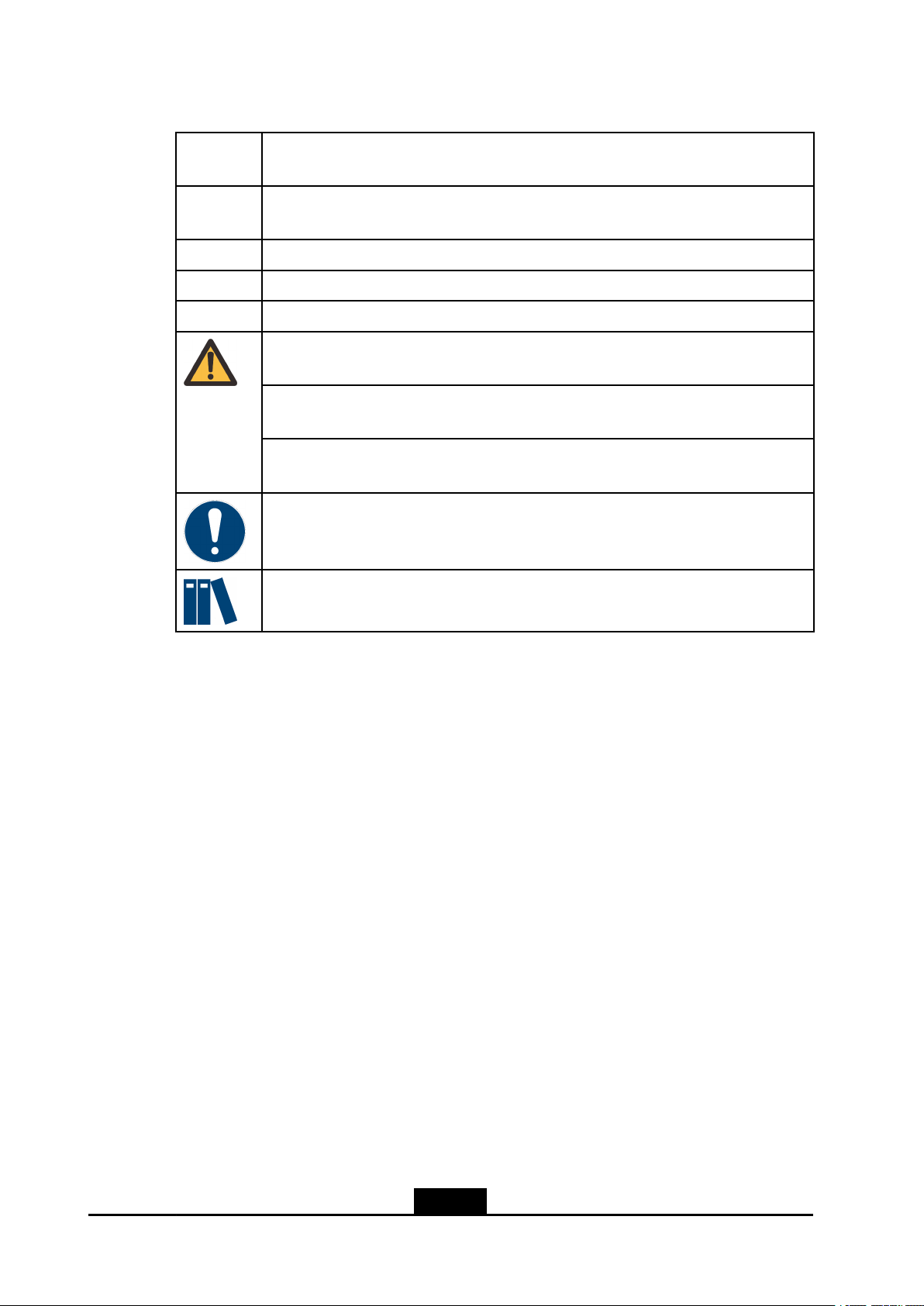
BoldMenus,menuoptions,functionnames,inputelds,optionbuttonnames,checkboxes,
drop-downlists,dialogboxnames,windownames,parameters,andcommands.
Constant
width
[]Optionalparameters.
{}Mandatoryparameters.
|Separatesindividualparametersinaseriesofparameters.
Textthatyoutype,programcodes,lenames,directorynames,andfunctionnames.
Danger:indicatesanimminentlyhazardoussituation.Failuretocomplywillresultin
deathorseriouspersonalinjury.
Warning:indicatesapotentiallyhazardoussituation.Failuretocomplycanresultin
deathorseriouspersonalinjury.
Caution:indicatesapotentiallyhazardoussituation.Failuretocomplycanresultin
moderateorminorpersonalinjury.
Notice:indicatesequipmentorenvironmentsafetyinformation.Failuretocomply
canresultinequipmentdamage,dataloss,equipmentperformancedegradation,
environmentalcontamination,orotherunpredictableresults.
Note:providesadditionalinformationaboutatopic.
II
SJ-20160405141455-003|2018-01-03(R1.3)ZTEProprietaryandCondential
Page 7
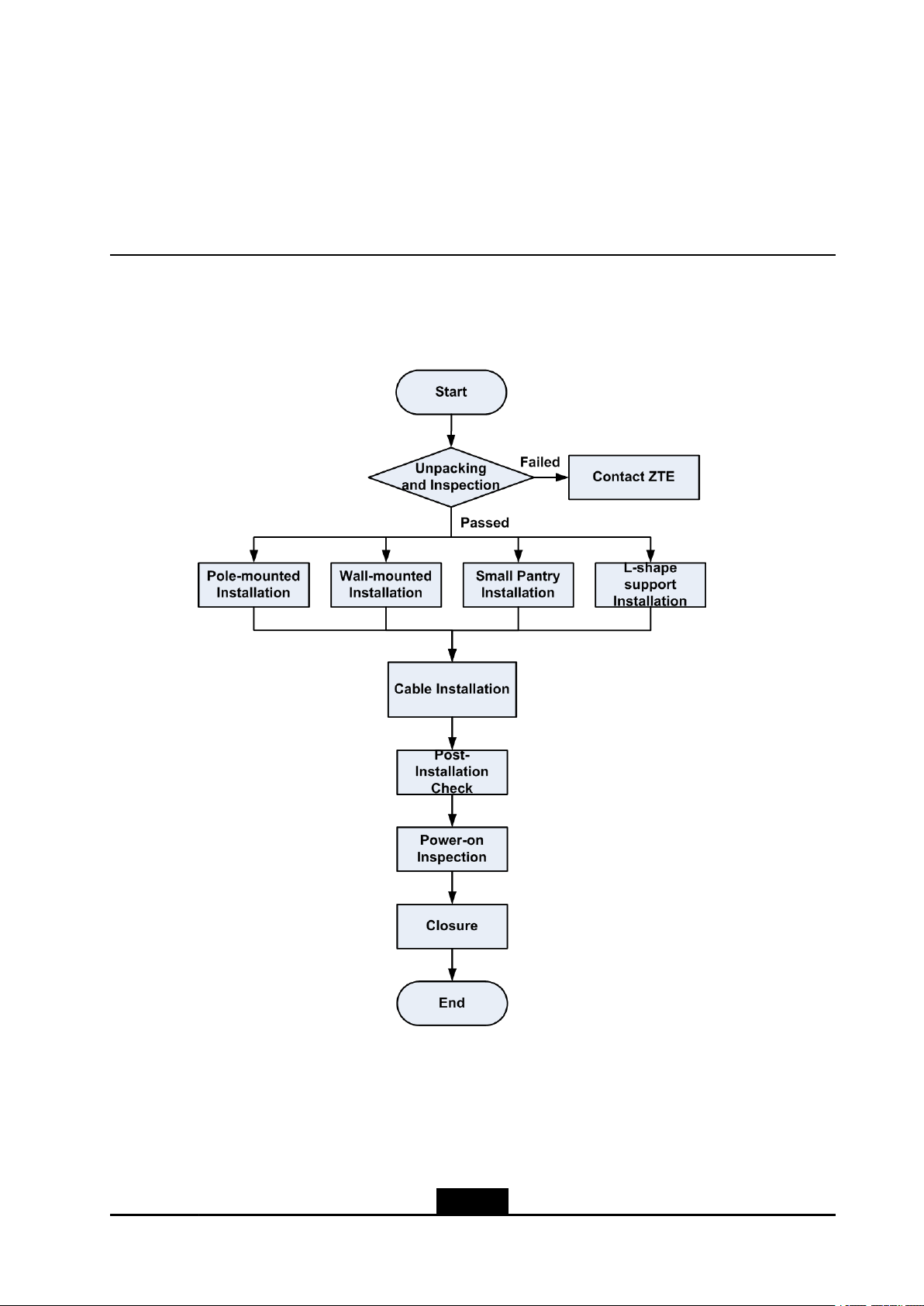
Chapter1
InstallationFlow
FortheinstallationowoftheZXSDRR8854,seeFigure1-1.
Figure1-1ZXSDRR8854InstallationFlow
1-1
SJ-20160405141455-003|2018-01-03(R1.3)ZTEProprietaryandCondential
Page 8

ZXSDRR8854HardwareInstallation
Thispageintentionallyleftblank.
1-2
SJ-20160405141455-003|2018-01-03(R1.3)ZTEProprietaryandCondential
Page 9
Chapter2
InstallationPreparations
BeforeinstallingtheZXSDRR8854,installationengineersshouldchecktheinstallation
environmentanddeliveranEnvironmentAcceptanceReport.
Installationparts,tools,andinstrumentsshouldbeavailablebeforeinstallation.
Caution!
TheZXSDRR8854mustbepoweredonwithin24hoursafteritisunpacked.
Thepower-offdurationoftheZXSDRR8854mustnotbegreaterthan24hoursduring
maintenance.
TableofContents
PrecautionsforDeviceTransport...............................................................................
PrecautionsforDeviceHoisting..................................................................................2-1
InstallationPrecautions..............................................................................................2-4
InstrumentsandMetersList.......................................................................................
InstallationSpaceRequirement..................................................................................2-7
2.1PrecautionsforDeviceTransport
lAdevicemustbetransportedwiththeouterpackingcontainertoprotectthedevice
fromscratches.
lAfterthepackingcontainerisremovedonsite,thedevicemustbeprotectedwhen
youmoveorstoreit.Forexample,whenadeviceisstoredtemporarily,cushioning
materialsmustbeputunderthebottomofthedevicetoavoiddirectcontactwiththe
groundandsurroundingobjects.
lWhenyoutransportadevice,cushioningmaterialssuchasfoamedplasticand
paperboardmustbeusedtoprotectthedevicefromscratches.Whenyoulifta
deviceup,thedevicemustbedraggedproperlytoavoidcollisionwithotherobjects.
2.2PrecautionsforDeviceHoisting
2-1
2-6
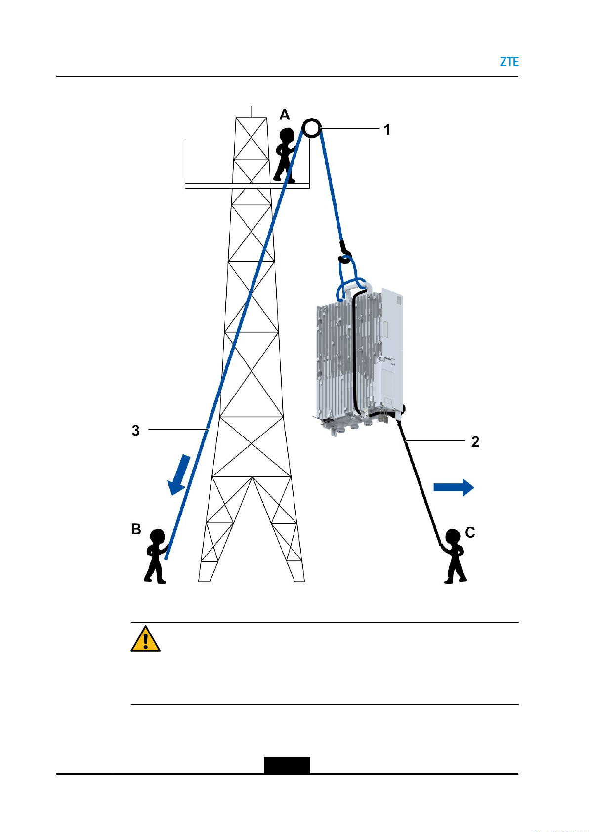
TheinformationprovidedisusedforreferencewhenitisnecessarytohoisttheRRU.
1.InstallerAonthetowersecuresthexedpulleytothetower,andpassesthehoisting
ropethroughthexedpulleydowntotheground,seeFigure2-1.
2-1
SJ-20160405141455-003|2018-01-03(R1.3)ZTEProprietaryandCondential
Page 10
ZXSDRR8854HardwareInstallation
Figure2-1DeviceHoisting
1.Fixedpulley2.Haulingrope3.Hoistingrope
Caution!
InstallerAonthetowercannotloosenthexedropeuntilheconrmsthatthedevice
issecurelyplacedonthetowerplatform.
2.InstallerConthegroundbindstheRRUtightly ,seeFigure2-2.
2-2
SJ-20160405141455-003|2018-01-03(R1.3)ZTEProprietaryandCondential
Page 11
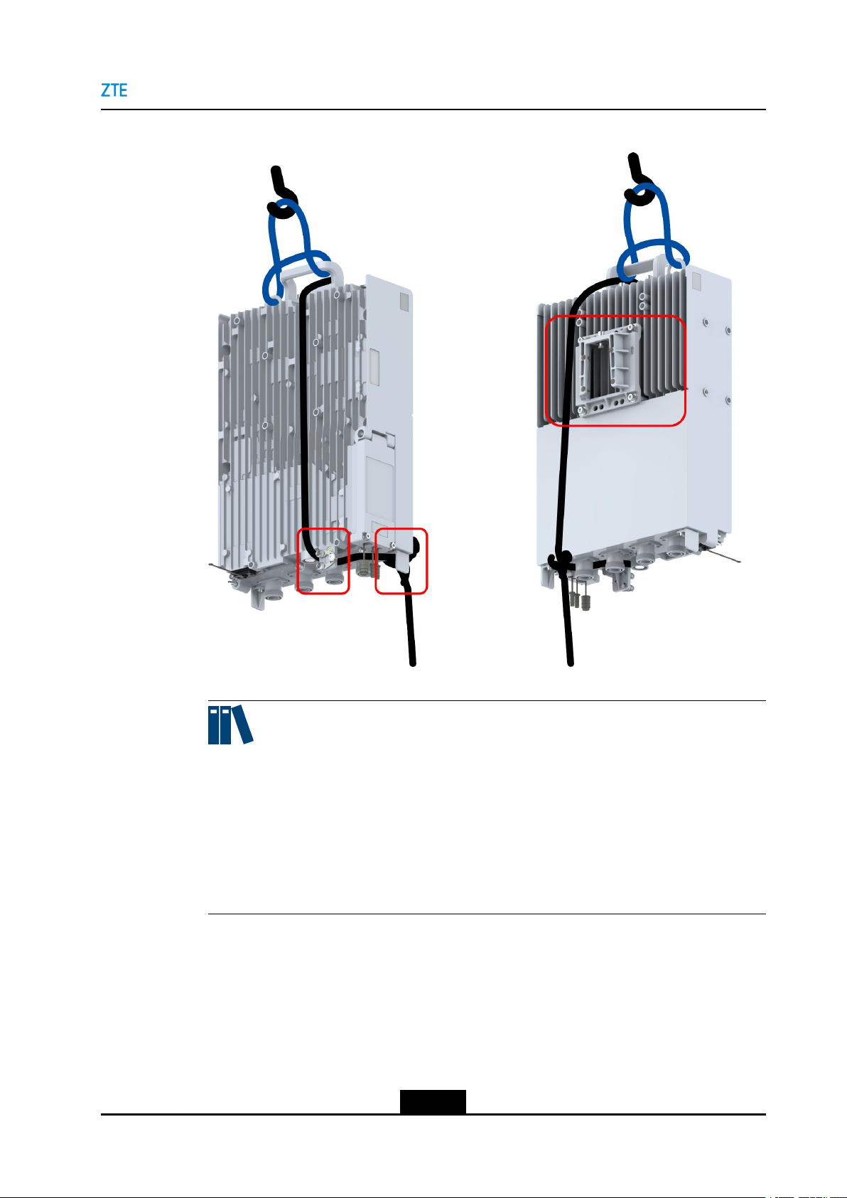
Figure2-2BindstheRRU
Chapter2InstallationPreparations
Note:
Passthehoistingropethroughthehandleandhoistinghole.
PassthehaulingropethroughthehandleonthetopoftheRRU,avoidingtheRRU
mountingbracket,andgettheropestuckbetweenthegroundingpointandthe
protectionblockatthebottomoftheRRU.BundletheRRUwiththeropebetween
thegroundingpointandtheprotectionblockatthebottomoftheRRU,ensuringthat
theRRUisbundledrmly.
3.InstallerBonthegrounddragsthehoistingropedownwards.Atthesametime,
installerCpullsthehaulingropeoutwardstoprotectthedevicefromcollidingwith
thetowerwhenthedevicereachesthemountingplatform,seeFigure2-1.
4.Lifttheproperly-packedengineeringmaterialsusedfortowermountingontothetower
inthemannermentionedabove.
2-3
SJ-20160405141455-003|2018-01-03(R1.3)ZTEProprietaryandCondential
Page 12
ZXSDRR8854HardwareInstallation
2.3InstallationPrecautions
Caution!
Neverlifttheengineeringmaterialsbybindingthemdirectlytothehoistingrepe.
1.Donotopentheequipment'sairtightpart,seeFigure2-3.
Figure2-3DoNotOpentheAirtightPart
2.TheRRUboxhasalayerofrustproofpaintthatprotectsitfrombeingscratchedduring
transportationandinstallation.
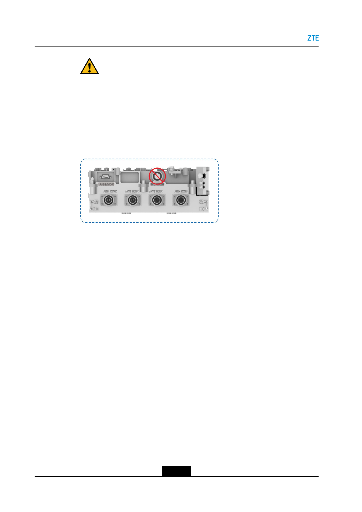
3.Donotinstallanyportupwards,seeFigure2-4.
2-4
SJ-20160405141455-003|2018-01-03(R1.3)ZTEProprietaryandCondential
Page 13
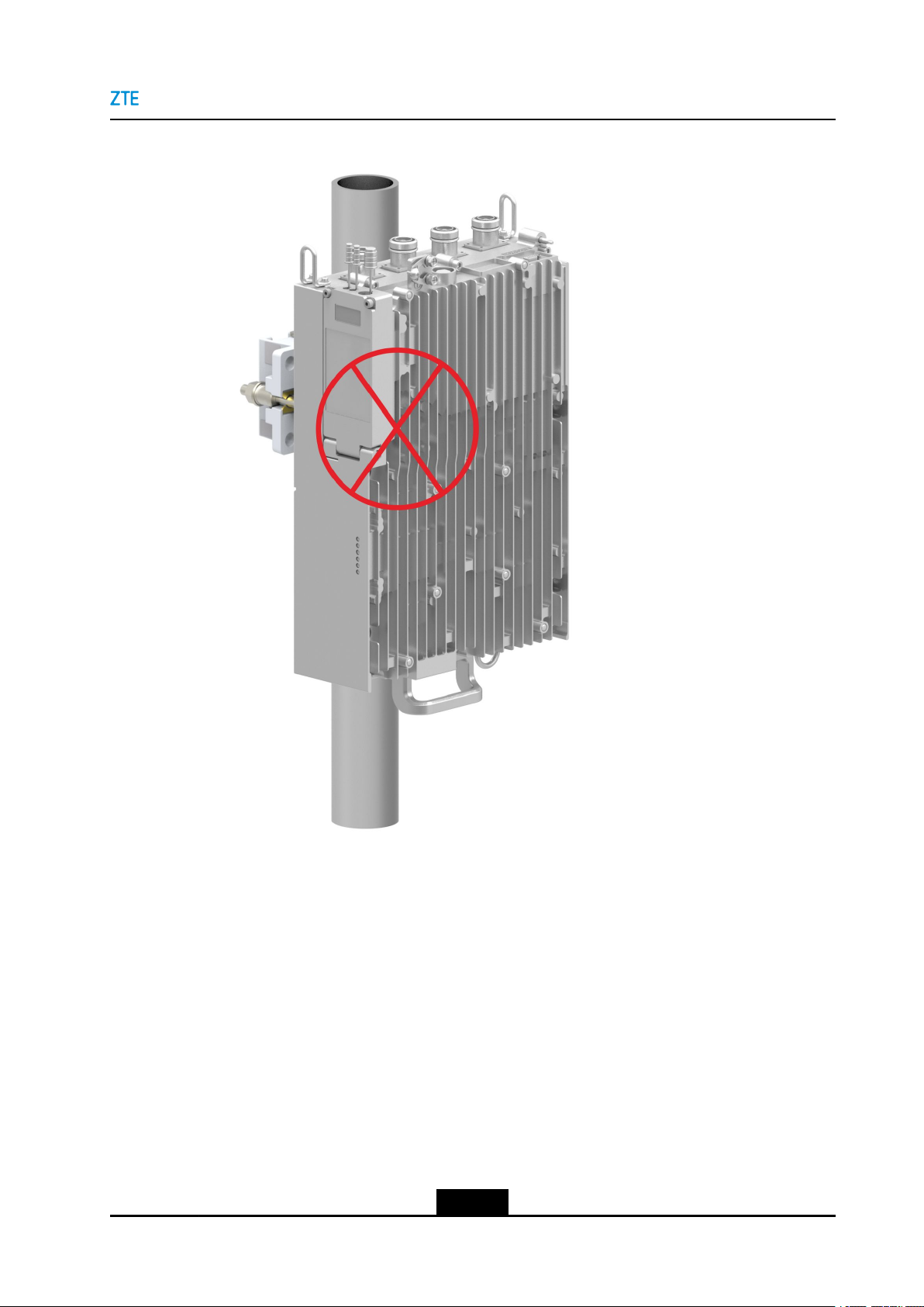
Figure2-4DoNotInstallAnyPortUpwards
Chapter2InstallationPreparations
4.Donotusethehorizontalinstallationmode,seeFigure2-5.
2-5
SJ-20160405141455-003|2018-01-03(R1.3)ZTEProprietaryandCondential
Page 14
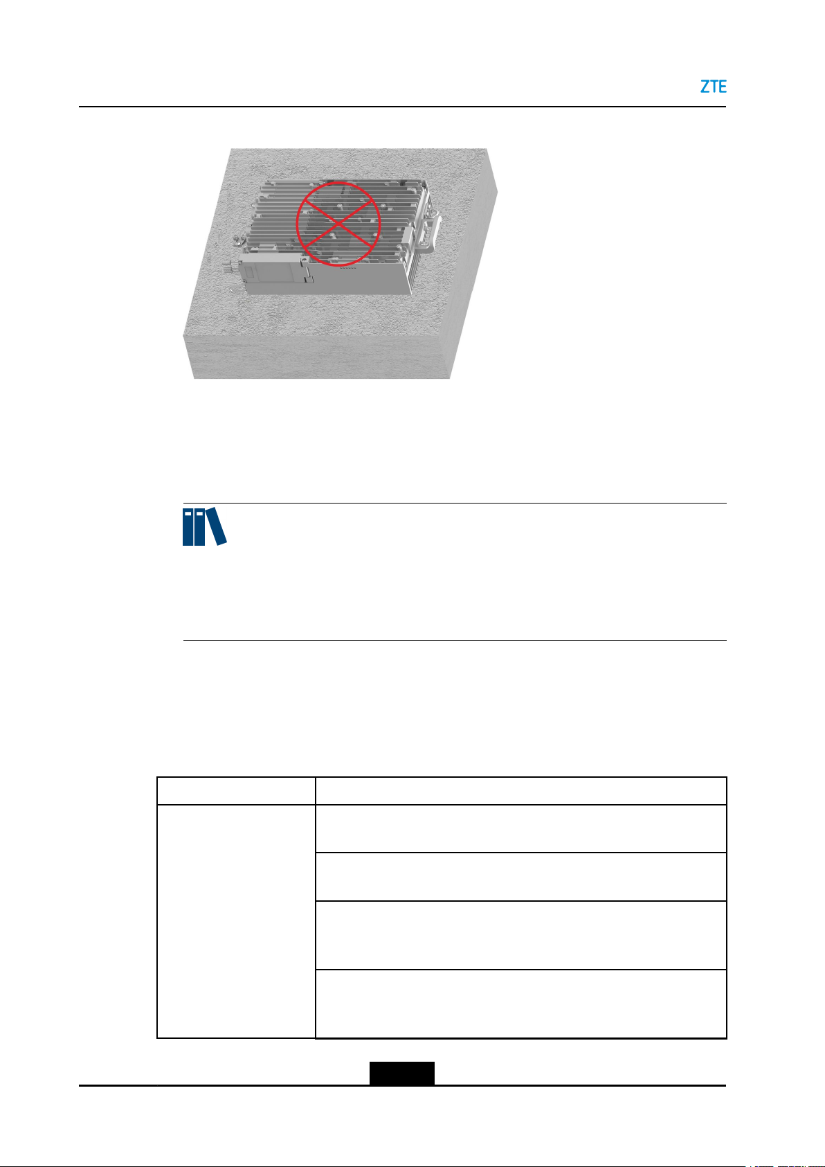
ZXSDRR8854HardwareInstallation
Figure2-5DoNotInstalltheRRUHorizontally
5.Thedevicemustbeinstalledinaspecialareawhereprotectionmeasuresaretaken
andonlymaintenancepersonnelunderthecontroloftheresponsibleunitcanenter.
6.Beforemaintainingthedevice,poweroffthedevicetocoolitdown.Thedevicecannot
beoperateduntilthecasetemperatureisbelow70°Ctoavoidscald.
Note:
Thedurationforcoolingthedevicedownafterpower-offcannotbelongerthanthe
maintenancetime.Thedurationforwaitingforthecooldownshouldbedetermined
throughtesting.
2.4InstrumentsandMetersList
Table2-1liststheinstrumentsandmetersrequiredforinstallingtheZXSDRR8854.
Table2-1InstrumentsandMetersList
ItemList
General-purpose
instruments
Measuringandrulinginstruments:
5msteeltape,1mruler,gradienter,marker,drillingtemplate
Drillinginstruments:
Electricpercussiondrill(auxiliarydrillbits)andvacuumcleaner
Tighteninginstruments:
Crossscrewdrivers(M3–M6),Allenkey(M5–M6),adjustablewrench
(M10),andtorquewrench
Smallinstruments:
Snipe-nosepliers,diagonalpliers,vices,le,hacksaw,andhydraulic
pressurepliers
2-6
SJ-20160405141455-003|2018-01-03(R1.3)ZTEProprietaryandCondential
Page 15
ItemList
Chapter2InstallationPreparations
Auxiliaryinstruments:
Chainwheel,Ladder,Rope,scissors,slip-proofgloves,safetyhelmet,
connectorcard,paintbrush,andhotairblower
Special-purpose
instruments
MetersDigitalmultimeter,VSWRtester,earthresistancetester,basestation
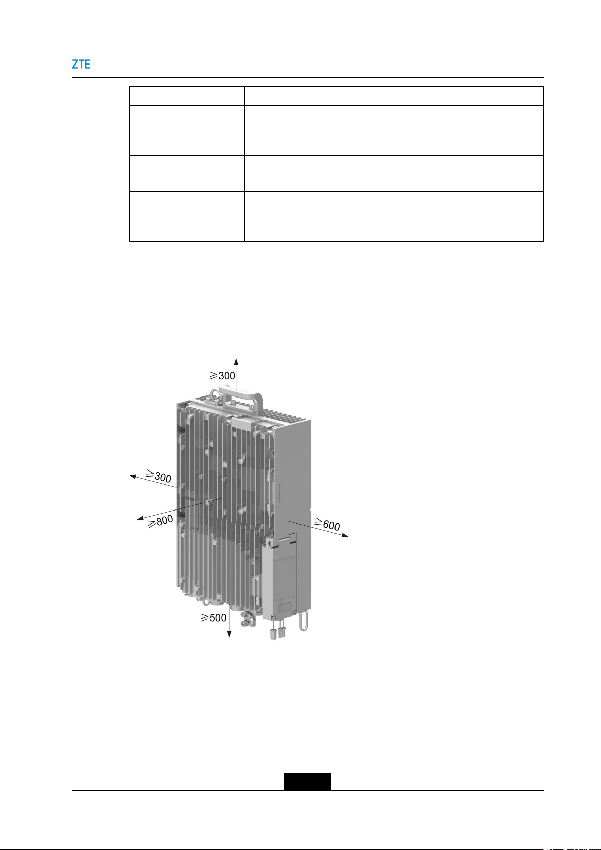
2.5InstallationSpaceRequirement
Figure2-6showstherecommendedspaceforinstallingZXSDRR8854.
Figure2-6RecommendedSpaceforInstallingZXSDRR8854(inmm)
Multi-functionalcrimpingpliersandfeederconnectorknife
tester,compass,eldstrengthtester(forspecialpurpose),andspectrum
analyzer(forspecialpurpose)
Figure2-7showstheminimumspaceforinstallingZXSDRR8854.
2-7
SJ-20160405141455-003|2018-01-03(R1.3)ZTEProprietaryandCondential
Page 16
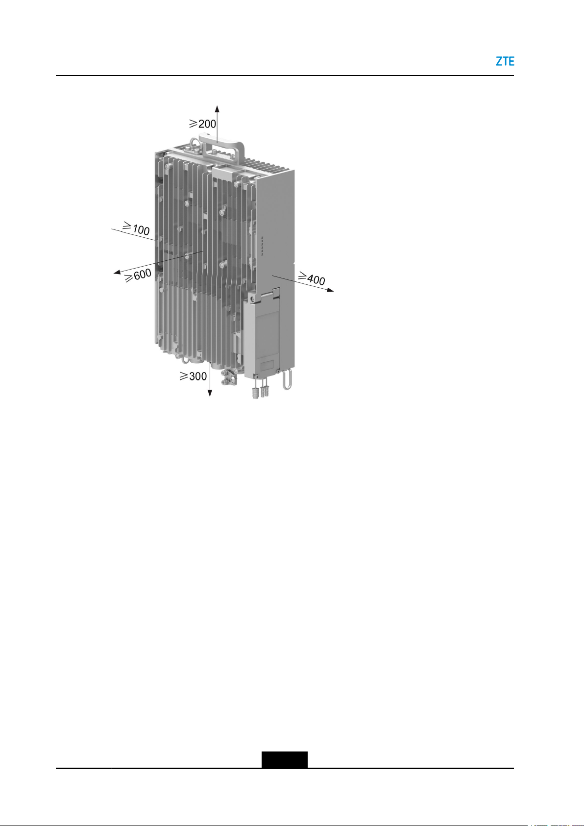
ZXSDRR8854HardwareInstallation
Figure2-7MinimumSpaceforInstallingZXSDRR8854(inmm)
2-8
SJ-20160405141455-003|2018-01-03(R1.3)ZTEProprietaryandCondential
Page 17

Chapter3
UnpackingandInspection
CountingGoods
lVerifythatthepackagingboxesareintact.Ifanydamageisfound,contactthe
transportcompanyimmediately.
lUnpacktheboxesandverifythatthegoodsareconsistentwiththeinspection
checklist.
lVerifythatthechassisisingoodconditionwithoutscratches,peelingpaint,blisters,
orstains.
lVerifythattheaccessoriesrequiredfortheinstallationarecorrectandcomplete.
EquipmentHandover
Aftertheexaminationofgoods,theengineeringsupervisorandtheoperator's
representativeshouldsigntheUnpackingAcceptanceReport.TheUnpackingAcceptance
Reportismadeinduplicate,andkeptbybothparties.Theengineeringsupervisormust
sendtheUnpackingAcceptanceReportbacktotherepresentativeofcewithinseven
daysforarchiving.
3-1
SJ-20160405141455-003|2018-01-03(R1.3)ZTEProprietaryandCondential
Page 18

ZXSDRR8854HardwareInstallation
Thispageintentionallyleftblank.
3-2
SJ-20160405141455-003|2018-01-03(R1.3)ZTEProprietaryandCondential
Page 19
Chapter4
RRUInstallation
TheZXSDRR8854canbeinstalledinthefollowingways:
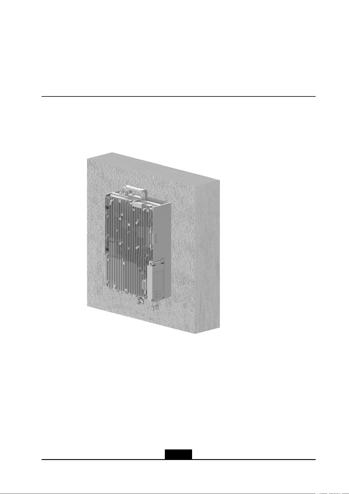
lWall-mountedinstallation,seeFigure4-1.
Figure4-1Wall-MountedInstallation
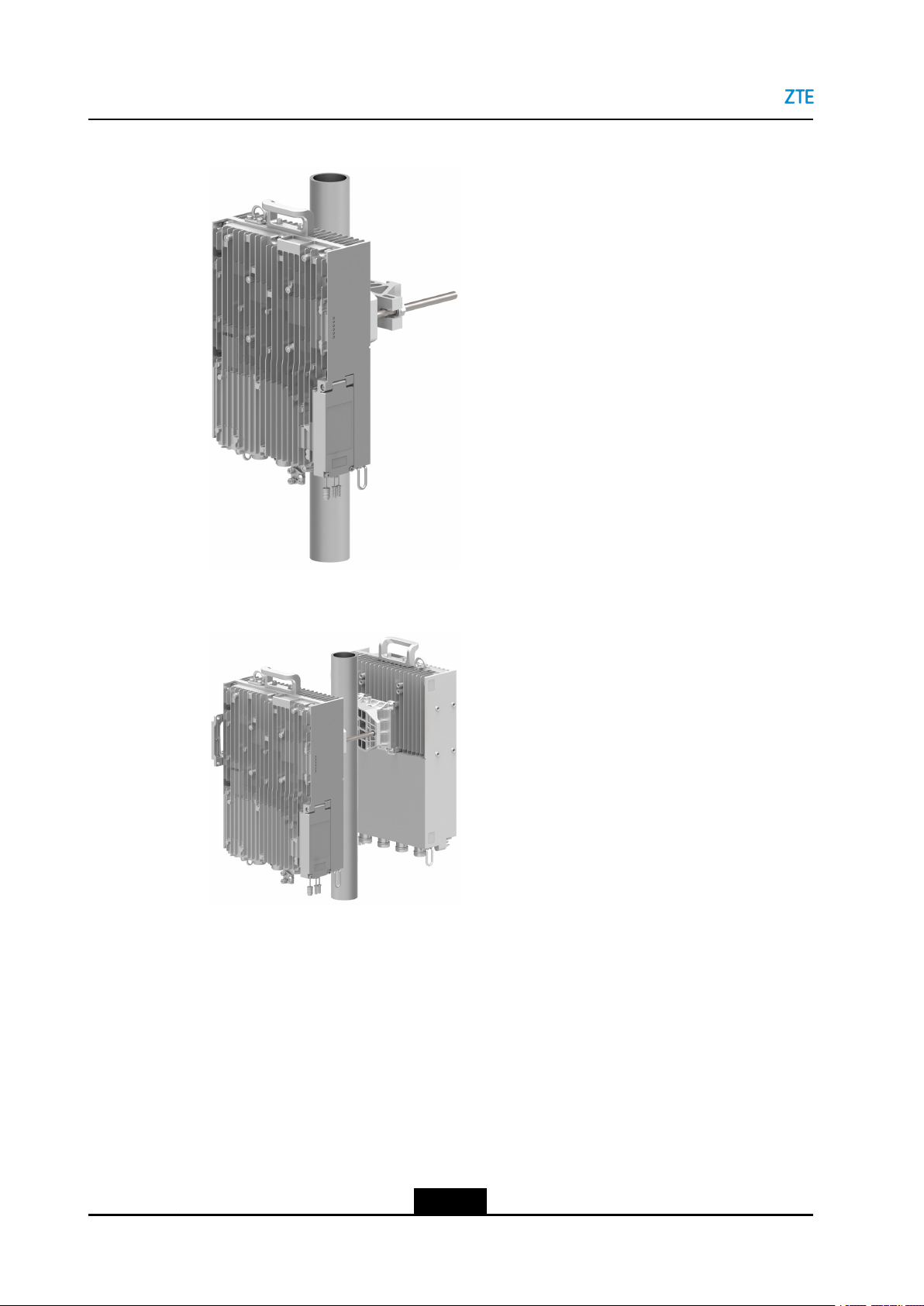
lPole-mountedinstallation,seeFigure4-2,Figure4-3andFigure4-4.
4-1
SJ-20160405141455-003|2018-01-03(R1.3)ZTEProprietaryandCondential
Page 20
ZXSDRR8854HardwareInstallation
Figure4-2Pole-MountedInstallationofaSingleRRU
Figure4-3Pole-MountedInstallationofT woRRUs
4-2
SJ-20160405141455-003|2018-01-03(R1.3)ZTEProprietaryandCondential
Page 21
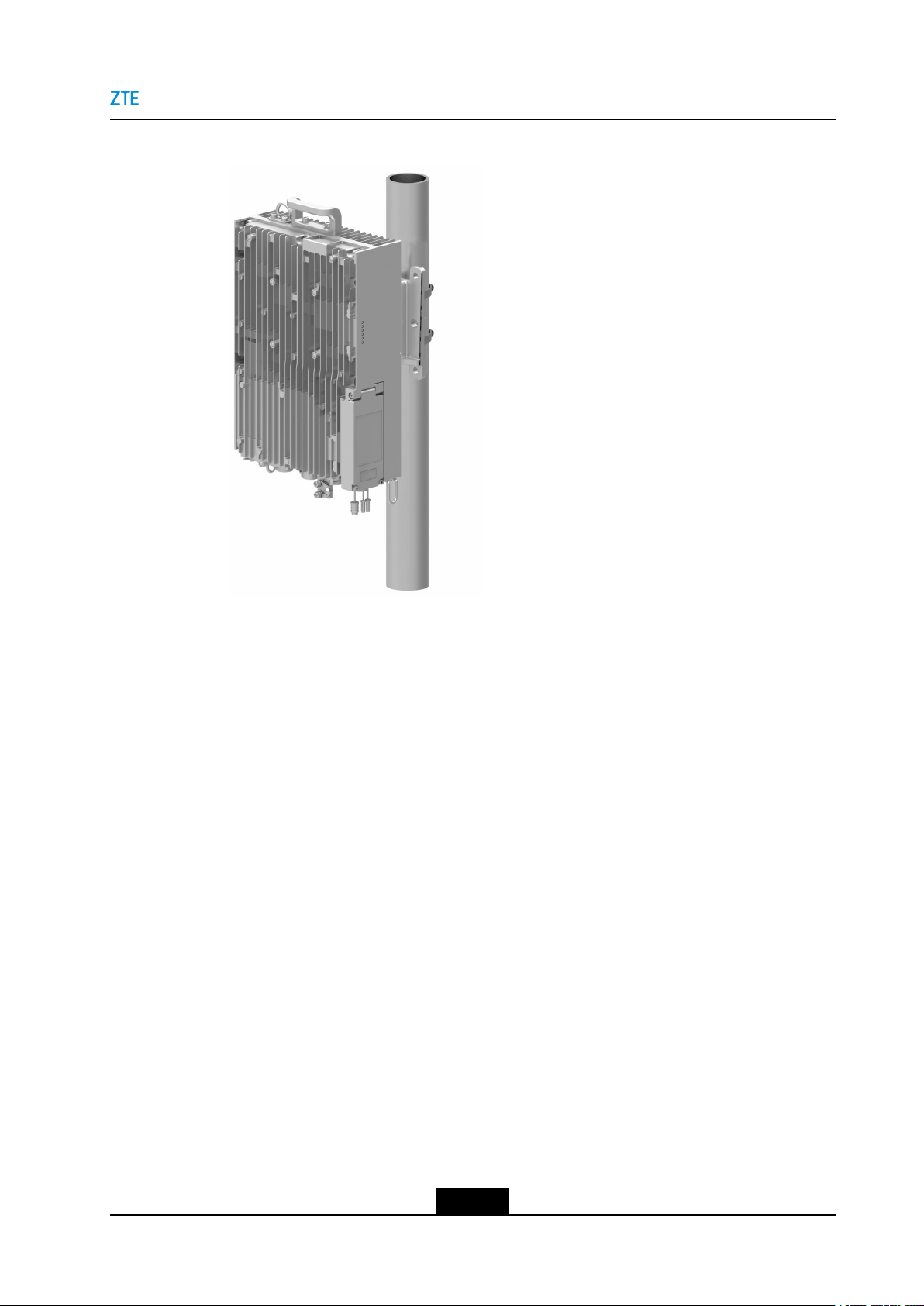
Figure4-4PoleHoop-MountedInstallationofaSingleRRU
Chapter4RRUInstallation
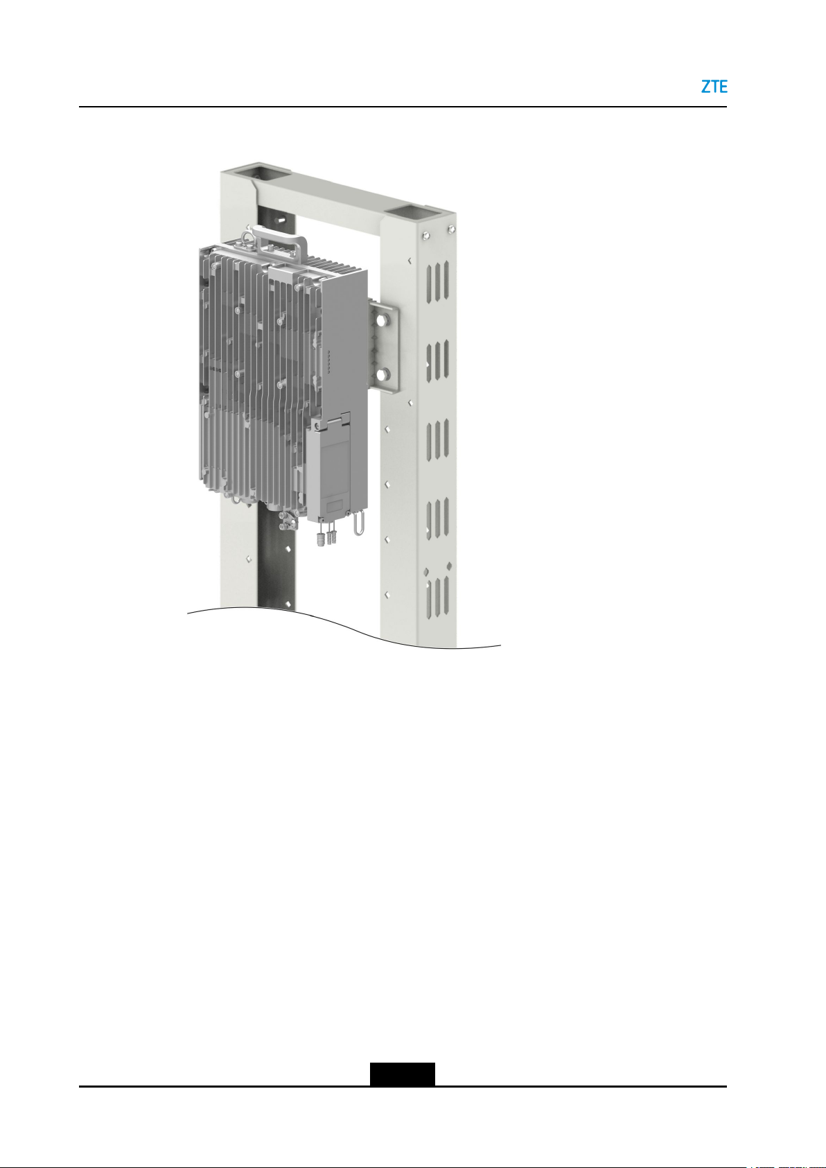
lGantry-mountedinstallation,seeFigure4-5.
4-3
SJ-20160405141455-003|2018-01-03(R1.3)ZTEProprietaryandCondential
Page 22
ZXSDRR8854HardwareInstallation
Figure4-5Gantry-MountedInstallation
lL-shapesupportinstallation,seeFigure4-6.
4-4
SJ-20160405141455-003|2018-01-03(R1.3)ZTEProprietaryandCondential
Page 23

Figure4-6L-shapeSupportInstallation
Chapter4RRUInstallation
TableofContents
InstallinganRRUonaWall........................................................................................4-5
InstallingaSingleRRUonaPole.............................................................................4-11
InstallingTwoRRUsonaPole.................................................................................4-17
InstallingaSingleRRUinPoleHoop-MountedMode...............................................4-22
InstallinganRRUonaGantry..................................................................................4-27
InstallinganRRUonaL-shapeSupport...................................................................4-32
4.1InstallinganRRUonaWall
AnRRUcanbeinstalledonawallwhenusedindoors,outdoors,orinahigh-speedrail
scenario.
ThisproceduredescribeshowtoinstalltheZXSDRR8854onawall.
Context
ForadescriptionoftheaccessoriesusedforinstallinganRRUonawall,refertoT able
4-1.
4-5
SJ-20160405141455-003|2018-01-03(R1.3)ZTEProprietaryandCondential
Page 24

ZXSDRR8854HardwareInstallation
Table4-1AccessoriesforWall-MountedInstallation
NameExternalView
Fixingclamp
RRUsupport
Steps
DrillingaHole
1.Marktheholepositionsonthewallwithadrillingtemplate,seeFigure4-7.
Figure4-7InstallationPositionsofExpansionBolts
4-6
SJ-20160405141455-003|2018-01-03(R1.3)ZTEProprietaryandCondential
Page 25

Chapter4RRUInstallation
2.Drillan80mm-deepholeinthemarkedpositionwithaφ12drillbit.Makesurethat
theholeisverticaltothewallandremovedustwithavacuumcleanerduringdrilling.
InstallinganExpansionBolt
3.Installanexpansionbolt,seeFigure4-9.
Figure4-8showsanexternalviewofanexpansionbolt.
Figure4-8ExternalViewofanExpansionBolt
1.Nut
2.Springwasher
3.Flatwasher
4.Bolt
5.Expansiontube
4-7
SJ-20160405141455-003|2018-01-03(R1.3)ZTEProprietaryandCondential
Page 26

ZXSDRR8854HardwareInstallation
Figure4-9InstallinganExpansionBolt
StepDescription
aSlightlyturntheexpansionboltclockwisetopreventitfrommovingfreely.
bBeforehammeringtheexpansionboltwithaclawhammer,takeanutwith
thesamespecicationsasthenutofthisexpansionboltandturnthenut
untilthetopofnutisushwiththatoftheexpansionbolttoavoiddamaging
thethreadduringhammering.
cHammertheexpansionboltintotheinstallationholewithaclawhammer.
dFastenthenutneartheexpansiontubeclockwisetoallowtheexpansionbolt
tofullyexpand.
eLoosenthenutcounterclockwiseandremovethenut,springwasher ,andat
washerinturnforuseduringsubsequentinstallation.
InstallingtheFixingClamp
4.Securethexingclamptothewallwithatorqueof40N•m,withthenuts,spring
washers,andatwashersremovedfromtheexpansionbolts,seeFigure4-10.
4-8
SJ-20160405141455-003|2018-01-03(R1.3)ZTEProprietaryandCondential
Page 27

Figure4-10SecuringtheFixingClamp
Chapter4RRUInstallation
1.Nut2.Springwasher3.Flatwasher
Note:
Theyellowarrowonthexingclampshouldpointupwardsduringinstallation.
SecuringtheRRU
5.FixtheRRUsupporttothebackoftheRRUwithfourM6screwswithatorqueof8
N•m,seeFigure4-11.
4-9
SJ-20160405141455-003|2018-01-03(R1.3)ZTEProprietaryandCondential
Page 28

ZXSDRR8854HardwareInstallation
Figure4-11InstallingtheRRUSupport
6.InstalltheRRUsupporttothexingclamp,seeFigure4-12.
Figure4-12InstallingtheRRUSupporttotheFixingClamp
7.TightenthecaptivescrewonthetopoftheRRUsupportwithanM6Allenhexwrench,
seeFigure4-13.
4-10
SJ-20160405141455-003|2018-01-03(R1.3)ZTEProprietaryandCondential
Page 29

Figure4-13SecuringtheRRU
Chapter4RRUInstallation
–EndofSteps–
4.2InstallingaSingleRRUonaPole
AsingleRRUcanbeinstalledonaroundpole(φ40–120mm),achannelsteelpole
(φ60–100mm),orananglesteelpole(φ63–100mm).
Thefollowingdescriptionandprocedurearebasedonroundpole-mountedinstallation.
Figure4-14andFigure4-15showchannelsteelpole-mountedinstallationandanglesteel
pole-mountedinstallationrespectively.
4-11
SJ-20160405141455-003|2018-01-03(R1.3)ZTEProprietaryandCondential
Page 30

ZXSDRR8854HardwareInstallation
Figure4-14ChannelSteelPole-MountedInstallation
Figure4-15AngleSteelPole-MountedInstallation
Context
ForadescriptionoftheaccessoriesusedforinstallingasingleRRUonapole,referto
Table4-2.
Table4-2AccessoriesforSingle-RRUPole-MountedInstallation
NameExternalView
Polecomponent
(pole-mountedmode
ofasingleRRU)
4-12
SJ-20160405141455-003|2018-01-03(R1.3)ZTEProprietaryandCondential
Page 31

Chapter4RRUInstallation
NameExternalView
RRUsupport
Steps
FixingthePoleMountAssembly
1.InsertanM10screwthroughtheinstallationholeontheonesideofthexingclip,and
installtheplatwasher,springwasher,andnutontheothersideofthehole,seeFigure
4-16.
Figure4-16AssemblingthePoleMountAssembly
1.Screw
2.Fixingclip
3.Installationbracket
4.Flatwasher
5.Springwasher
6.Nut
2.AssemblethepolecomponenttothepolethroughtheU-shapeopensideofthe
installationbracket,andtheninstallthescrewintotheU-shapeslot,seeFigure4-17.
4-13
SJ-20160405141455-003|2018-01-03(R1.3)ZTEProprietaryandCondential
Page 32

ZXSDRR8854HardwareInstallation
Figure4-17InstallingthePoleMountAssembly(1)
Note:
Wheninstallingthexingclip,ensurethattheyellowarrowofthexingclipisupward.
3.Tightenthenutsonbothsidesofthepolecomponentwithanadjustablewrenchtox
thepolecomponentonthepole,seeFigure4-18.
4-14
SJ-20160405141455-003|2018-01-03(R1.3)ZTEProprietaryandCondential
Page 33

Figure4-18InstallingthePoleMountAssembly(2)
Chapter4RRUInstallation
InstallingtheRRUSupport
4.FixtheRRUsupporttothebackoftheRRUwithfourM6screwswithatorqueof8
N•m,seeFigure4-19.
Figure4-19InstallingtheRRUSupport
SecuringtheRRU
4-15
SJ-20160405141455-003|2018-01-03(R1.3)ZTEProprietaryandCondential
Page 34

ZXSDRR8854HardwareInstallation
5.MounttheZXSDRR8854tothepolecomponentalongtherailofthexingclip,see
Figure4-20.
Figure4-20InstallingtheRRUonthePoleMountAssembly
6.TightenthecaptivescrewontheRRUsupportwithanM6inner-hexagonwrenchto
xtheZXSDRR8854,seeFigure4-21.
Figure4-21SecuringtheRRU
–EndofSteps–
4-16
SJ-20160405141455-003|2018-01-03(R1.3)ZTEProprietaryandCondential
Page 35

4.3InstallingTwoRRUsonaPole
ThisproceduredescribeshowtoinstalltwoRRUsonapole.Theprocedureforinstalling
twoRRUsonapoleissimilartothatforinstallingasingleone.
Context
ForadescriptionoftheaccessoriesusedforinstallingtwoRRUsonapole,refertoT able
4-3.
Table4-3AccessoriesforT wo-RRUPole-MountedInstallation
NameExternalView
Polecomponent
(pole-mountedmode
oftwoRRUs)
Chapter4RRUInstallation
RRUsupport
Steps
FixingthePoleMountAssembly
1.InsertanM10screwthroughtheinstallationholeontheonesideofthexingclip,and
installtheplatwasher,springwasher,andnutontheothersideofthehole,seeFigure
4-22.
4-17
SJ-20160405141455-003|2018-01-03(R1.3)ZTEProprietaryandCondential
Page 36

ZXSDRR8854HardwareInstallation
Figure4-22AssemblingthePoleComponent
1.Screw
2.Fixingclip
3.Flatwasher
4.Springwasher
5.Nut
2.Assemblethepolecomponenttothepole,andinstallthescrewontheothersideof
thexingclip,seeFigure4-23.
Figure4-23InstallingthePoleComponent(1)
3.Tightenthenutsonbothsidesofthepolecomponentwithanadjustablewrenchwith
atorqueof40Nmtoxthepolecomponentonthepole,seeFigure4-24.
4-18
SJ-20160405141455-003|2018-01-03(R1.3)ZTEProprietaryandCondential
Page 37

Figure4-24InstallingthePoleComponent(2)
Chapter4RRUInstallation
Note:
Whentighteningthenuts,youneedtoadjustthepositionofthescrewsandensure
thattheexposedlengthsofthescrewsonbothsidesofthexingcliparethesame.
Otherwise,RRUinstallationmaybeaffected.
InstallingtheRRUSupport
4.FixtheRRUsupporttothebackoftheRRUwithfourM6screwswithatorqueof8
N•m,seeFigure4-25.
4-19
SJ-20160405141455-003|2018-01-03(R1.3)ZTEProprietaryandCondential
Page 38

ZXSDRR8854HardwareInstallation
Figure4-25InstallingtheRRUSupport
SecuringtheRRUs
5.InstallthetwoRRUsonthepolemountassemblyalongtheguiderailsonthexing
clampsrespectively ,seeFigure4-26.
4-20
SJ-20160405141455-003|2018-01-03(R1.3)ZTEProprietaryandCondential
Page 39

Figure4-26InstallingtheRRUsonthePoleMountAssembly
Chapter4RRUInstallation
6.TightenthecaptivescrewsonthetopofalltheRRUsupportswithanM6Allenhex
wrenchrespectively ,seeFigure4-27.
4-21
SJ-20160405141455-003|2018-01-03(R1.3)ZTEProprietaryandCondential
Page 40

ZXSDRR8854HardwareInstallation
Figure4-27SecuringtheRRUs
–EndofSteps–
4.4InstallingaSingleRRUinPoleHoop-MountedMode
ThisproceduredescribeshowtoinstalltheZXSDRR8854throughpolehoops.This
installationmodeisapplicabletothepolewiththediameterof120mm-380mm.
Context
Fortherequiredinstallationaccessoriesofpolehoop-mountedmode,refertoTable4-4.
4-22
SJ-20160405141455-003|2018-01-03(R1.3)ZTEProprietaryandCondential
Page 41

Chapter4RRUInstallation
Table4-4InstallationAccessoriesofPoleHoop-MountedInstallationModeofaSingle
RRU
AccessoryOverview
Fixingclip
Polehoop
ZXSDRR8854support
Steps
1.InstalltheRRUsupporttotherearpaneloftheZXSDRR8854withfourM6screws,
seeFigure4-28.
4-23
SJ-20160405141455-003|2018-01-03(R1.3)ZTEProprietaryandCondential
Page 42

ZXSDRR8854HardwareInstallation
Figure4-28InstallingtheRRUSupport
2.Installthexingcliptothepole,seeFigure4-29.
a.Installpolehoopstothexingclip.
b.Fixthexingcliponthepolethroughthepolehoops.
4-24
SJ-20160405141455-003|2018-01-03(R1.3)ZTEProprietaryandCondential
Page 43

c.Tightenthescrewsonthepolehoops.
Chapter4RRUInstallation
4-25
SJ-20160405141455-003|2018-01-03(R1.3)ZTEProprietaryandCondential
Page 44

ZXSDRR8854HardwareInstallation
Figure4-29InstallingtheFixingCliptothePole
3.MounttheZXSDRR8854tothexingcliponthepolealongtherailofthexingclip,
seeFigure4-30.
Figure4-30MountingtheZXSDRR8854
4-26
SJ-20160405141455-003|2018-01-03(R1.3)ZTEProprietaryandCondential
Page 45

Chapter4RRUInstallation
4.TightenthecaptivescrewontheRRUsupportwithanM6inner-hexagonwrenchto
xtheZXSDRR8854,seeFigure4-31.
Figure4-31TighteningtheCaptiveScrew
–EndofSteps–
4.5InstallinganRRUonaGantry
ThisproceduredescribeshowtoinstallanRRUonagantry .
Context
ForadescriptionoftheaccessoriesusedforinstallinganRRUonagantry,refertoT able
4-5.
4-27
SJ-20160405141455-003|2018-01-03(R1.3)ZTEProprietaryandCondential
Page 46

ZXSDRR8854HardwareInstallation
Table4-5AccessoriesforGantry-MountedInstallation
NameExternalView
Gantry
Fixingclamp
Adapterplate
4-28
SJ-20160405141455-003|2018-01-03(R1.3)ZTEProprietaryandCondential
Page 47

Chapter4RRUInstallation
NameExternalView
RRUsupport
Steps
1.FixtheadapterplatetothegantrywithfourM8boltsandnutswithatorqueof20N•m,
seeFigure4-32.
Figure4-32InstallingtheAdapterPlate
1.Bolt
2.Adapterplate
3.Flatwasher
4.Springwasher
2.SecurethexingclamptotheadapterplatewithfourM10boltsandnutswithatorque
of40N•m,seeFigure4-33.
4-29
SJ-20160405141455-003|2018-01-03(R1.3)ZTEProprietaryandCondential
5.Nut
Page 48

ZXSDRR8854HardwareInstallation
Figure4-33SecuringtheFixingClamp
3.FixtheRRUsupporttothebackoftheRRUwithfourM6screwswithatorqueof8
N•m,seeFigure4-34.
4-30
SJ-20160405141455-003|2018-01-03(R1.3)ZTEProprietaryandCondential
Page 49

Figure4-34InstallingtheRRUSupport
Chapter4RRUInstallation
4.InstalltheRRUonthegantryalongtheguiderailofthexingclampandtightenthe
captivescrewonthetopoftheRRUsupportwithanM6Allenhexwrench,seeFigure
4-35.
Figure4-35InstallingtheRRUontheGantry
4-31
SJ-20160405141455-003|2018-01-03(R1.3)ZTEProprietaryandCondential
Page 50

ZXSDRR8854HardwareInstallation
–EndofSteps–
4.6InstallinganRRUonaL-shapeSupport
ThisproceduredescribeshowtoinstallanRRUonaL-shapesupport.
Context
ForadescriptionoftheaccessoriesusedforinstallinganRRUonaL-shapesupport,refer
toT able4-6.
4-32
SJ-20160405141455-003|2018-01-03(R1.3)ZTEProprietaryandCondential
Page 51

Table4-6AccessoriesforL-shapeSupportInstallation
NameExternalView
L-shapesupport
Chapter4RRUInstallation
Fixingclamp
RRUsupport
4-33
SJ-20160405141455-003|2018-01-03(R1.3)ZTEProprietaryandCondential
Page 52

ZXSDRR8854HardwareInstallation
Steps
1.SecurethexingclamptotheadapterplatewithfourM10boltsandnutswithatorque
of40N•m,seeFigure4-36.
Figure4-36SecuringtheFixingClamp
2.FixtheRRUsupporttothebackoftheRRUwithfourM6screwswithatorqueof8
N•m,seeFigure4-37.
4-34
SJ-20160405141455-003|2018-01-03(R1.3)ZTEProprietaryandCondential
Page 53

Figure4-37InstallingtheRRUSupport
Chapter4RRUInstallation
3.InstalltheRRUontheL-shapesupportalongtheguiderailofthexingclampand
tightenthecaptivescrewonthetopoftheRRUsupportwithanM6Allenhexwrench,
seeFigure4-38.
Figure4-38InstallingtheRRUontheL-shapeSupport
4-35
SJ-20160405141455-003|2018-01-03(R1.3)ZTEProprietaryandCondential
Page 54

ZXSDRR8854HardwareInstallation
–EndofSteps–
4-36
SJ-20160405141455-003|2018-01-03(R1.3)ZTEProprietaryandCondential
Page 55

Chapter5
CableInstallation
CableList
ItemLocalEquipmentInterconnectedEquipment
Ground-
ingCa-
ble
DC
Power
Cable
Optical
Cable
ExternalView
Connector
Type
Interconnected
Port
ExternalView
Connector
Type
Interconnected
Port
ExternalView
Connector
Type
Interconnected
Port(RRU-
BBU)
ExternalView
OTterminalOTterminal
LocalgroundingterminalofRRUGroundingbar
TubularterminalCold-pressedterminal
LocalpowerterminalofRRU,
madeonsite.
DLC,LCDLC,FC×2,LC,SC
Cable'sRRUendconnectedtothe
OPT1
UsedtoconnectDCPD,madeon
site.
Cable'sBBUendconnectedtothe
BBU
Connector
Type
Interconnected
Port(RRU-
RRU)
RF
Cable
SJ-20160405141455-003|2018-01-03(R1.3)ZTEProprietaryandCondential
ExternalView
Connector
Type
Interconnected
Port
DLC,LCDLC,LC
TheOPT2portoftheupper-layer
RRU
DIN-typemaleconnectorDIN-typemaleconnector
ANTportAntenna'sRFport
5-1
TheOPT1portofthelower-layer
RRU
Page 56

ZXSDRR8854HardwareInstallation
ItemLocalEquipmentInterconnectedEquipment
AISG
Cable
MON
Cable
CableConnectionDiagram
ExternalView
Connector
Type
Interconnected
Port
ExternalView
Connector
Type
Interconnected
Port
DB15connectorAISGconnector
LocalAISG/MONportofRRURCU'sAISGportofthetunable
antenna
DB15connectorNakedcables
LocalAISG/MONportofRRUExternalmonitoringdevice
5-2
SJ-20160405141455-003|2018-01-03(R1.3)ZTEProprietaryandCondential
Page 57

Figure5-1CableConnectionDiagram
Chapter5CableInstallation
1.DCpowercable
2.Opticalcable
3.Groundingcable
4.RFCable
TableofContents
InstallingtheProtectiveGroundingCable...................................................................
InstallingAntennaFeederCables...............................................................................
InstallingaMonitoringCable......................................................................................5-7
InstallingtheAISGCable...........................................................................................5-8
InstallingtheDCPowerInputCable.........................................................................5-10
InstallinganOpticalFiberCable...............................................................................5-15
UnusedInterfaceProtection.....................................................................................
5.1InstallingtheProtectiveGroundingCable
Thisproceduredescribeshowtoinstalltheprotectivegroundingcable.Theprotective
groundingcableisacopper-corecablewithacross-sectionalareaof16mm
5-3
5.AISG/MONCable
2
5-3
5-5
5-18
.
SJ-20160405141455-003|2018-01-03(R1.3)ZTEProprietaryandCondential
Page 58

ZXSDRR8854HardwareInstallation
Steps
1.Routetheprotectivegroundingcablefromtheindoororoutdoorgroundingbusbarto
theRRU.
2.CrimpanOTterminalattheRRUendoftheprotectivegroundingcable.
3.Fixoneendoftheprotectivegroundingcabletothegroundingscrewatthebottomof
theZXSDRR8854,seeFigure5-2.
Figure5-2ConnectingtheProtectiveGroundingCabletotheGroundingBusbar
(Directly)
Note:
About30cmofthecableshoulddroopfreelybeforethecableisroutedtothepoleor
cabletray.
4.RemovetherustonthegroundingbusbarandcrimpanOTterminalattheotherend
oftheprotectivegroundingcable.
5.Connecttheotherendoftheprotectivegroundingcabletothegroundingbusbarand
xittoabolt,seeFigure5-2.
5-4
SJ-20160405141455-003|2018-01-03(R1.3)ZTEProprietaryandCondential
Page 59

6.Bundleandlabelthecable.
7.Applyantirustpaintaroundthegroundingboltsonthegroundingbusbar.
–EndofSteps–
5.2InstallingAntennaFeederCables
Thisproceduredescribeshowtoinstallanantennafeedercable.
Therearetwotypesofantennafeedercables,antennafeedersandjumpers.Thedistance
betweentheRRUandtheantennadetermineshowtoinstallanantennafeedercable.For
details,refertoT able5-1.
Table5-1AntennaFeederCableInstallation
If...Then...
Chapter5CableInstallation
Thedistancebetweenthebasestationand
theantennaislessthanvemeters
Thedistancebetweenthebasestationand
theantennaisgreaterthanvemetersand
lessthan20meters
Afeederjumperisused.
A1/2"feederisused.
Steps
1.(Optional)Installaheat-shrinksleeveonthefeederconnectorifafeederconnector
needstobemadeonsite,seeFigure5-3.
Figure5-3MakingaFeederConnector
Note:
Ifthedistancebetweenthebasestationandtheantennaisgreaterthanvemeters,
bothfeedersandjumpersareusedforconnection.Inthiscase,feederconnectors
shouldbemadeonsite.
2.ConnectthefeedercabletotheantennafeederinterfaceontheRRUchassis,see
Figure5-4.
5-5
SJ-20160405141455-003|2018-01-03(R1.3)ZTEProprietaryandCondential
Page 60

ZXSDRR8854HardwareInstallation
Figure5-4InstallingAntennaFeederCables
3.Fastenthefeederconnectorclockwisewithaadjustablewrench.
4.Protectthecableconnectorsagainstwater.Fordetails,refertoChapter10
WaterproongOutdoorConnectors.
5.Laytheantennafeedercableontheantennasideandbinditwithblackcableties.
Thefeedershouldbelaidverticallyatleast200mmfromtheloweredgeofthedevice
whenitisledoutfromthebottomoftheRRUchassis.Itshouldnotbebent.The
minimumbendingradiusofthefeedershouldnotbelessthan20timesthefeeder's
radius.Itisprohibitedtocoilthefeeder.
5-6
SJ-20160405141455-003|2018-01-03(R1.3)ZTEProprietaryandCondential
Page 61

Chapter5CableInstallation
6.ConnecttheotherendofthefeedertotheANTinterfaceontheantenna.T ake
waterproofmeasures.
7.Labelthefeedercablewithplastic.
8.Repeatsteps1through7toinstallotherfeedercables,seeFigure5-5.
Figure5-5ZXSDRR8854AntennaFeederConnectionDiagram
–EndofSteps–
5.3InstallingaMonitoringCable
Thisproceduredescribeshowtoinstallamonitoring(MON)cable.
Amonitoringcableisusedtoconnectthedrycontactinterfaceofanexternalmonitoring
device.
Steps
1.ConnectoneendofthemonitoringcabletotheAISG/MONinterfaceatthebottomof
theZXSDRR8854chassis,seeFigure5-6.
5-7
SJ-20160405141455-003|2018-01-03(R1.3)ZTEProprietaryandCondential
Page 62

ZXSDRR8854HardwareInstallation
Figure5-6InstallingaMonitoringCable
2.Connecttheotherendofthemonitoringcabletothedrycontactinterfaceofthe
externalmonitoringdevice.
3.Bundleandlabelthecable.
–EndofSteps–
5.4InstallingtheAISGCable
AnAISGcablebetweentheRFmoduleandanRETantennaisusedtotransmitthesignals
toorfromtheRETantenna.
5-8
SJ-20160405141455-003|2018-01-03(R1.3)ZTEProprietaryandCondential
Page 63

Chapter5CableInstallation
Steps
1.ConnectoneendoftheAISGinterfacecabletotheAISG/MONportontheZXSDR
R8854,seeFigure5-7.
Figure5-7InstallingtheAISGCable
2.ConnecttheotherendtotheAISGportontheRETantenna.
3.Bundleandlabelthecable.
–EndofSteps–
5-9
SJ-20160405141455-003|2018-01-03(R1.3)ZTEProprietaryandCondential
Page 64

ZXSDRR8854HardwareInstallation
5.5InstallingtheDCPowerInputCable
ThisproceduredescribeshowtoinstalltheDCpowerinputcable.
Context
TheZXSDRR8854DCpowerconnectorsupportspowercableswiththesectionalareaof
2
4mm
or6mm
usedbecausethedistancebetweentheZXSDRR8854andanexternalpowersupplyis
toolong,aDCjunctionbox(ODCPD1)isneededtoconnectthepowercabletothatwith
thesectionareaof4mm
refertoChapter9InstallingtheDCJunctionBox.
Steps
Openthemaintenancewindow
1.OpenthemaintenancewindowatthesideoftheZXSDRR8854,seeFigure5-8.
Figure5-8Openthemaintenancewindow
2
.Ifthepowercablewiththesectionalareaof10mm
2
or6mm
2
.ForhowtoinstalltheDCjunctionbox(ODCPD1),
2
or16mm
2
mustbe
MakingthePowerCableConnector
2.Followthemaintenancewindowdiagramtotailorthenakedshieldinglayer,child
cables,andnakedcoppercores.Sheathethetailoredcoopercoreswithtubular
terminalsandusethecrimpingplierstocrimpthesetubularterminals,seeFigure5-9.
5-10
SJ-20160405141455-003|2018-01-03(R1.3)ZTEProprietaryandCondential
Page 65

Chapter5CableInstallation
Figure5-9Wirestrippingthepowercable
3.Passthetubularterminalroundthetrimmedbarecoppercoreandcrimpthetubular
terminalwiththecrimpingpliers.
4.Conrmthepolarityofthepowerconnector'ssocketconnectedtothepowercable.
5.Usethescrewdrivertopressthemandrilluntilitcannotreboundandstuffthetubular
terminalsintothecrimpingtube,seeFigure5-10.Itisrequiredthattheleadingends
ofconductorsbecompletelyinsertedandhaveaclosecontactwiththeinnerbottom
oftheconnector'splug.
Figure5-10Insertthecrimpedtubularterminal
1.Button
2.Pull-tabinsulator
3.Mandrill
4.Crimpingtube
5.Shell
Note:
Standardassemblyrequiresthattubularterminalscannotbepushedforwardany
more.
6.Presstheredandbluebuttons(youmayusetoolslikescrewdriverbutarenotallowed
touseheavytoolslikehammer,ortheplugmaybemanaged).Themandrillejects
automatically.Ifyoupulltheconductorwithyourhandbutitdoesnotfalldown,it
indicatestheconductorisinstalledsecurely.
ConnectingPowerCableontheRRU
5-11
SJ-20160405141455-003|2018-01-03(R1.3)ZTEProprietaryandCondential
Page 66

ZXSDRR8854HardwareInstallation
7.Inthemaintenancewindow,usethecrossscrewdrivertounscrewthecrimpingclip
andremovethewaterproofplug,seeFigure5-11.
Figure5-11Unscrewthecrimpingclip
8.Inserttheconductorplugintothepowerportinsidethemaintenancewindow,see
Figure5-12.Pushtheplugforwardunityouhearthesoundof"click".Ifyoushake
theplugshellbutitdoesnotloosenorfalldown(youarenotallowedtopulltheplug's
pull-tabatthistime),itindicatesthattheplugisinstalledsecurelyandlockedclosely.
Figure5-12Insertthepowercable
5-12
SJ-20160405141455-003|2018-01-03(R1.3)ZTEProprietaryandCondential
Page 67

Chapter5CableInstallation
9.Usethecrimpingcliptocrimpthenakedpartoftheshieldinglayer,securethepower
cableattheoriginalwaterproofplug,andensurethatthenakedparthasaclosecontact
withthecrimpingclip.
Note:
Thetopedgeofthepowercable'sblackoutersheathshallalignwiththebottomedge
ofthecrimpingclipandshallnotbelowerthanthetopedgeofthecardslot.
10.Wrapthepowercablealongthepoleorcabletryanduseblacktiestobundleand
secureit.
IftheDCJunctionBox(ODCPD1)isequipped,refertoChapter9InstallingtheDC
JunctionBox.
EarthingthePowerCable
11.Connectthepowercabletothegroundingbusbarthroughagroundingkitbasedon
thelocationofthebasebandcabinetconnectedtotheotherendofthepowercable,
seeFigure5-13.
If...Then...
Thebasebandcabinetis
installedoutdoors
Thebasebandcabinetis
installedindoors
Connectthepowercabletotheoutdoorgroundingbusbarthroughthe
groundingkitbeforethecableisledintothecableinletholeofthe
outdoorcabinet.
Connectthepowercabletothegroundingbusbarthroughthegrounding
kitbeforethecableisledintotheroomandnearthefeederwindow.
lProtectthegroundingkitagainstwaterwiththe"1+3+3"solutionif
thepowercableisearthedbeforebeingledintothefeederwindow,
refertoChapter10WaterproongOutdoorConnectors.
lWindthegroundingkitwithtwolayersofinsulatingtapeifthe
powercableisearthedafterbeingledintothefeederwindow.The
groundingcableisconnectedtotheoutdoorgroundingbusbar.
5-13
SJ-20160405141455-003|2018-01-03(R1.3)ZTEProprietaryandCondential
Page 68

ZXSDRR8854HardwareInstallation
Figure5-13ConnectingthePowerCabletotheGroundingKit
Note:
Whenagroundingkitisused,theanglebetweenthegroundingcableandthepower
cablecannotbeupwardorbegreaterthan15degrees.Ifthegroundingkitisawayfrom
thefeederwindow,thegroundingcableshouldberoutedtowardthefeederwindow
alongthedownwarddirectionofthepowercable.
ConnectingthePowercableofthePowerSupplyEquipment
12.UseatubularterminaltomaketheconnectoroftheACpowercableattheBBUside,
andthenconnecttheACpowercabletotheDCoutputportoftheDCPD,seeFigure
5-14.
Figure5-14ConnectingthePowerCabletotheDCPD
5-14
SJ-20160405141455-003|2018-01-03(R1.3)ZTEProprietaryandCondential
Page 69

WhenyoumaketheconnectoroftheDCpowercable,cutofftheexposedshielded
layerafterstrippingoffthecableendandbindtheconnectorwithaheatshrinktube
orinsulatingtape.
13.Labelthepowercableatbothends.
–EndofSteps–
5.6InstallinganOpticalFiberCable
Thisproceduredescribeshowtoinstallanopticalbercable.
Steps
InstallingOpticalFiber
1.Openthecrimpingclipattheleftsideofthemaintenancewindow,seeFigure5-15.
Figure5-15Openthecrimpingclip
Chapter5CableInstallation
2.Removethecabletieatoneendofthecorrugatedpipemarkedas"RRU"byusingthe
diagonalpliers.
3.Removethewhitedustcapoftheopticalcableconnector,seeFigure5-16.
Figure5-16Removethewhitedustcap
1.Whitedustcap
5-15
SJ-20160405141455-003|2018-01-03(R1.3)ZTEProprietaryandCondential
Page 70

ZXSDRR8854HardwareInstallation
Note:
Donotremovethedustcapduringthestorage,transportation,androutingbefore
installation.
4.InserttheopticalmoduleintotheportsOPT1andOPT2oftheRRU.Alignthe
connectorwiththeopticalinterfacemodule,andinsertit.Whenyouhearthesound
of"bang",itindicatesthattheopticalcableconnectorisinstalledproperly,seeFigure
5-17.
Figure5-17Inserttheopticalcable
Note:
InthecaseofcascadedconnectionwithRRUs,useanopticalberforcascading
connectiontoconnecttheOPT2portofupper-levelRRUandtheOPT1portof
lower-levelRRU.
5.Securetheopticalcableatthecrimpingclipinthewiringcavity ,seeFigure5-18.
Inthecaseofoneopticalcable,installittotheoutgoingslotattherightsideanduse
awaterproofrubberplugtoblocktheotherslot.
5-16
SJ-20160405141455-003|2018-01-03(R1.3)ZTEProprietaryandCondential
Page 71

Figure5-18Securetheopticalcable
Chapter5CableInstallation
Note:
Inthemaintenancewindow,thereshallbeacertainarcbetweentheopticalcable
connectorandtheopticalcable.Thebendingradiusshallbelargerthan40mm.
6.Bundleandxtheopticalbercable.
Theoutdooropticalbercableshouldbelaidverticallyatleast200mmfromthelower
edgeofthedevicewhenitisledoutfromthebottomoftheRRUchassis.Theoptical
bercableshouldnotbebent.Theopticalbercableisthenxedontothepoleor
cabletray .Coiltheexcesspartoftheopticalbercableinadiameterof300mmto
400mmandthenbindthebercoiltoanappropriateposition(forexample,thewire
spoolontheBBU)withblackcableties.
7.Removethecabletieatoneendofthecorrugatedpipemarkedas"BBU"byusingthe
diagonalpliersandinstallittotheopticaljunctionboxorBBU.
8.Hangtheplasticlabelofopticalcable.
Closethemaintenancewindow
5-17
SJ-20160405141455-003|2018-01-03(R1.3)ZTEProprietaryandCondential
Page 72

ZXSDRR8854HardwareInstallation
9.Puttheremainingwaterproofplugsbacktotheiroriginalpositionsafterinstallingall
powercablesandbers.Closethepanelofmaintenancewindowandinstallthe
screwssecurelytoavoidwaterpenetration.
Thescrewsmustbefastenedtopreventwaterintrusion.
–EndofSteps–
5.7UnusedInterfaceProtection
Afterinstallingallcables,youneedtoprotectallunusedinterfacesontheZXSDRR8854.
Steps
Caution!
1.Checkanunusedinterface.
Checkwhetheranunusedinterfaceiscoveredwithadustproofcap.Ifnot,coverit
withadustproofcap.
2.Waterproofadustproofcap.
Wrapitwithablackdouble-layerultraviolet-prooftape:therstlayerfromtopdown,
thesecondlayerfrombottomupaccordingtothedirectionoftighteningtheinterface.
Makesurethatthewrappedtapeisushwiththelowersurfaceofthecap.Tighten
theedgeofthetapewithacabletie.
–EndofSteps–
5-18
SJ-20160405141455-003|2018-01-03(R1.3)ZTEProprietaryandCondential
 Loading...