

Page 1
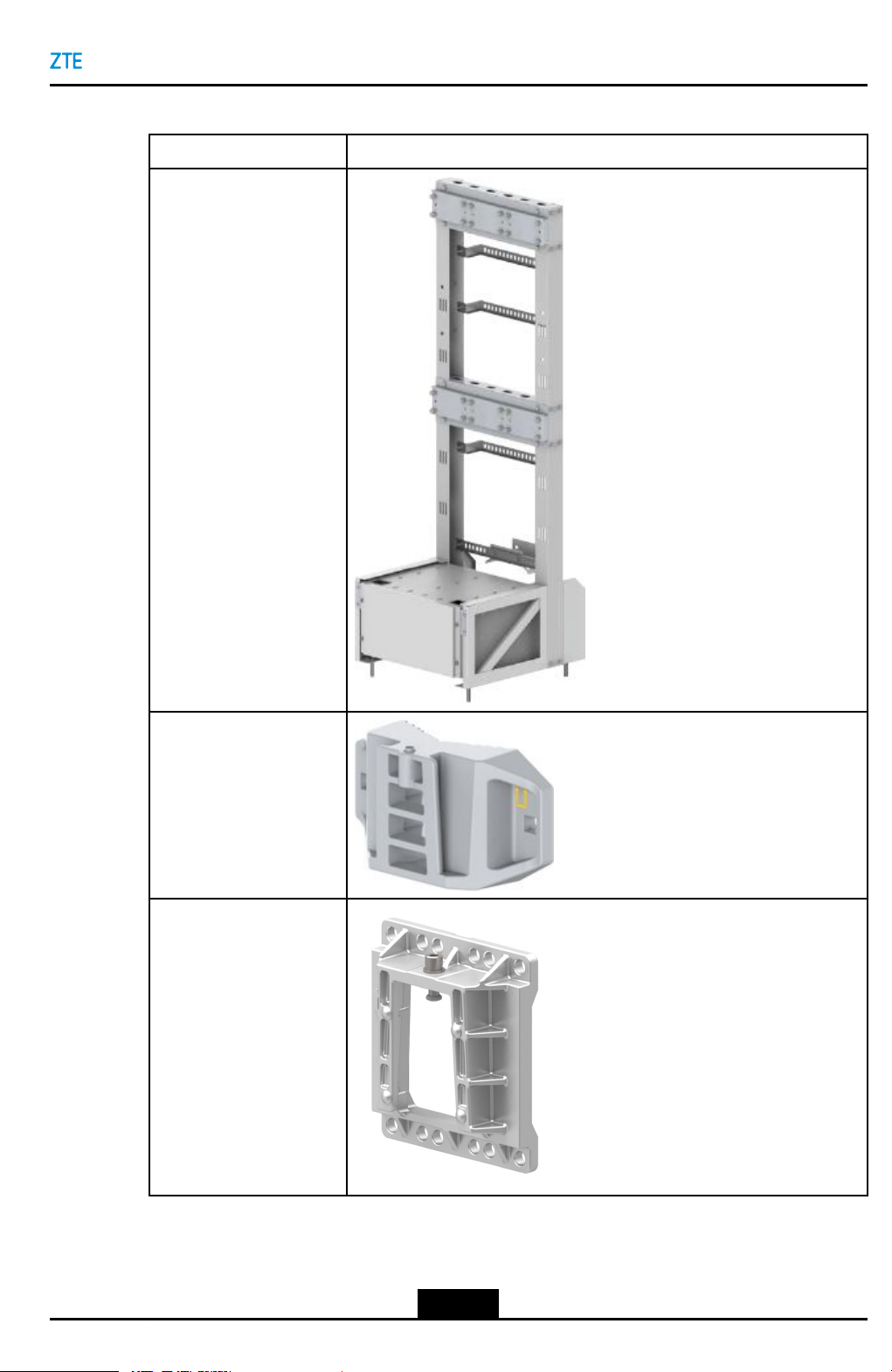
Table4-6AccessoriesforL-shapeSupportInstallation
NameExternalView
L-shapesupport
Chapter4RRUInstallation
Fixingclamp
RRUsupport
4-33
SJ-20160405141455-003|2018-01-03(R1.3)ZTEProprietaryandCondential
Page 2
ZXSDRR8854HardwareInstallation
Steps
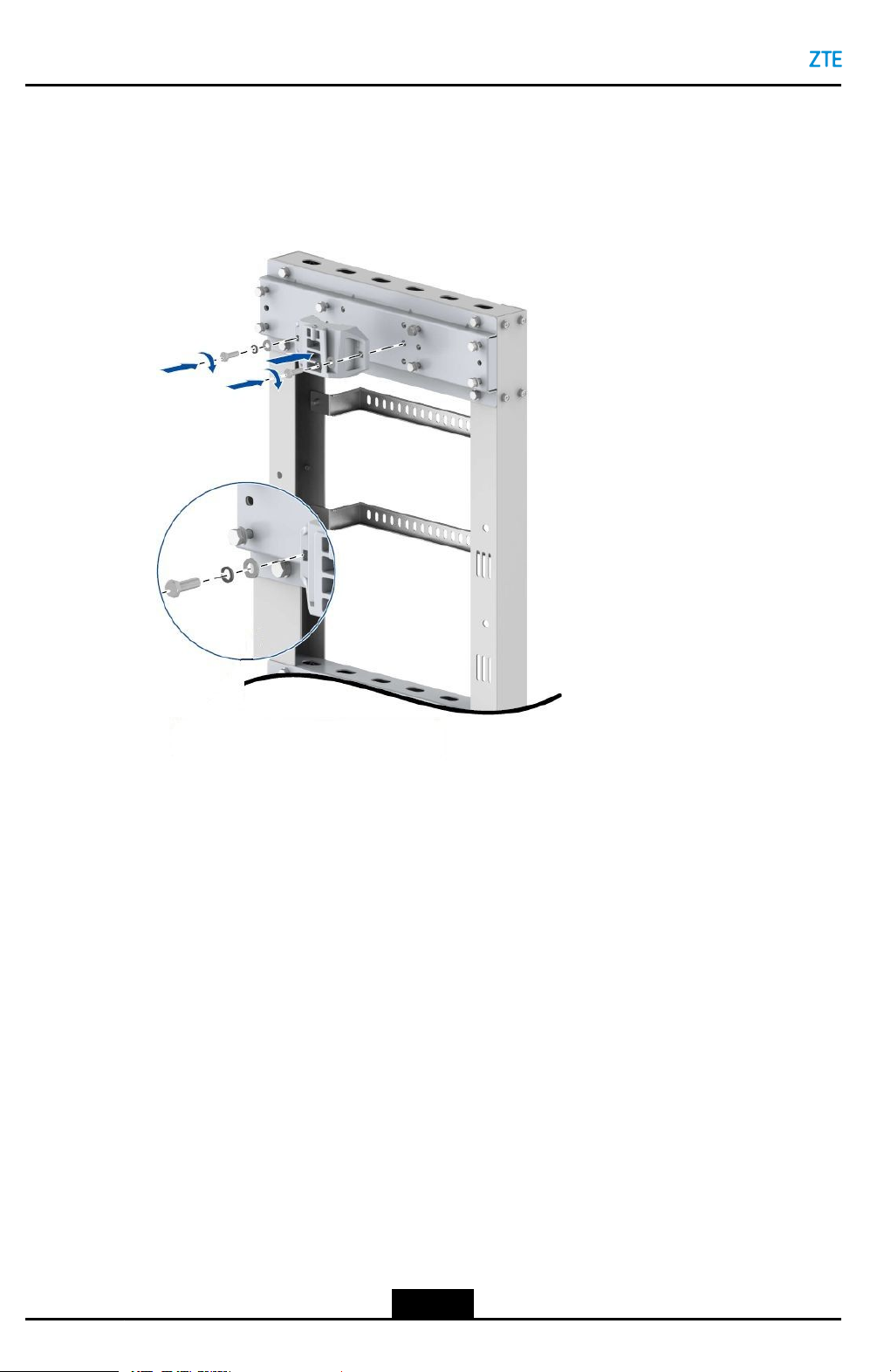
1.SecurethexingclamptotheadapterplatewithfourM10boltsandnutswithatorque
of40N•m,seeFigure4-36.
Figure4-36SecuringtheFixingClamp
2.FixtheRRUsupporttothebackoftheRRUwithfourM6screwswithatorqueof8
N•m,seeFigure4-37.
4-34
SJ-20160405141455-003|2018-01-03(R1.3)ZTEProprietaryandCondential
Page 3
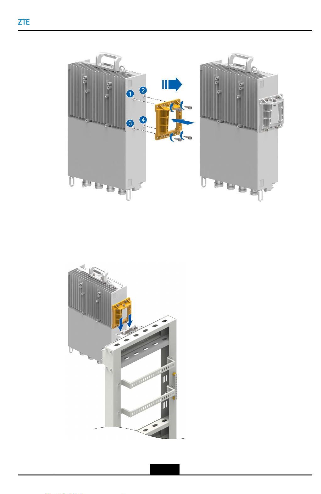
Figure4-37InstallingtheRRUSupport
Chapter4RRUInstallation
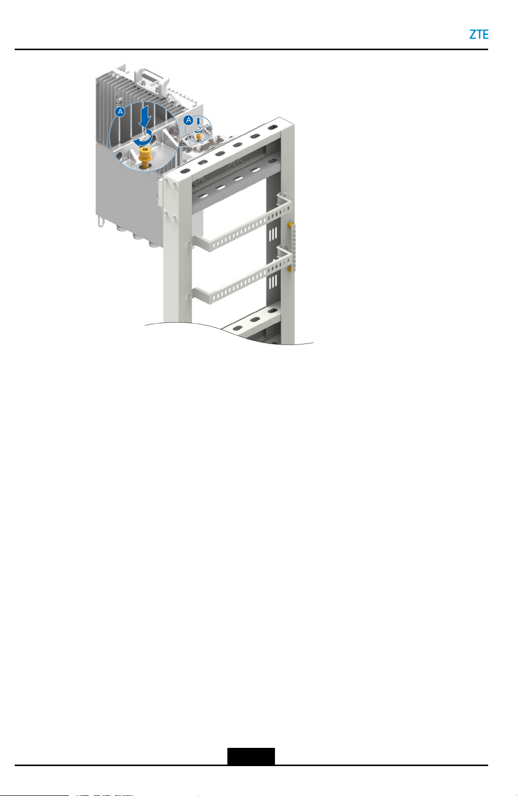
3.InstalltheRRUontheL-shapesupportalongtheguiderailofthexingclampand
tightenthecaptivescrewonthetopoftheRRUsupportwithanM6Allenhexwrench,
seeFigure4-38.
Figure4-38InstallingtheRRUontheL-shapeSupport
4-35
SJ-20160405141455-003|2018-01-03(R1.3)ZTEProprietaryandCondential
Page 4
ZXSDRR8854HardwareInstallation
–EndofSteps–
4-36
SJ-20160405141455-003|2018-01-03(R1.3)ZTEProprietaryandCondential
Page 5
Chapter5
CableInstallation
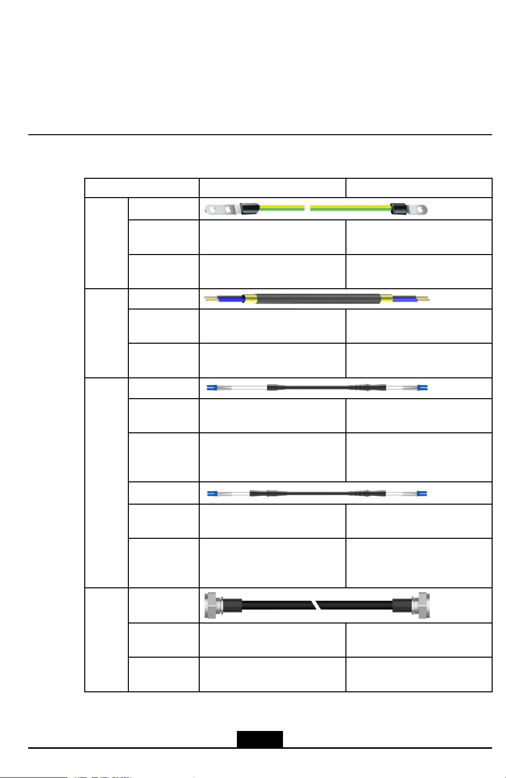
CableList
ItemLocalEquipmentInterconnectedEquipment
Ground-
ingCa-
ble
DC
Power
Cable
Optical
Cable
ExternalView
Connector
Type
Interconnected
Port
ExternalView
Connector
Type
Interconnected
Port
ExternalView
Connector
Type
Interconnected
Port(RRU-
BBU)
ExternalView
OTterminalOTterminal
LocalgroundingterminalofRRUGroundingbar
TubularterminalCold-pressedterminal
LocalpowerterminalofRRU,
madeonsite.
DLC,LCDLC,FC×2,LC,SC
Cable'sRRUendconnectedtothe
OPT1
UsedtoconnectDCPD,madeon
site.
Cable'sBBUendconnectedtothe
BBU
Connector
Type
Interconnected
Port(RRU-
RRU)
RF
Cable
SJ-20160405141455-003|2018-01-03(R1.3)ZTEProprietaryandCondential
ExternalView
Connector
Type
Interconnected
Port
DLC,LCDLC,LC
TheOPT2portoftheupper-layer
RRU
DIN-typemaleconnectorDIN-typemaleconnector
ANTportAntenna'sRFport
5-1
TheOPT1portofthelower-layer
RRU
Page 6
ZXSDRR8854HardwareInstallation
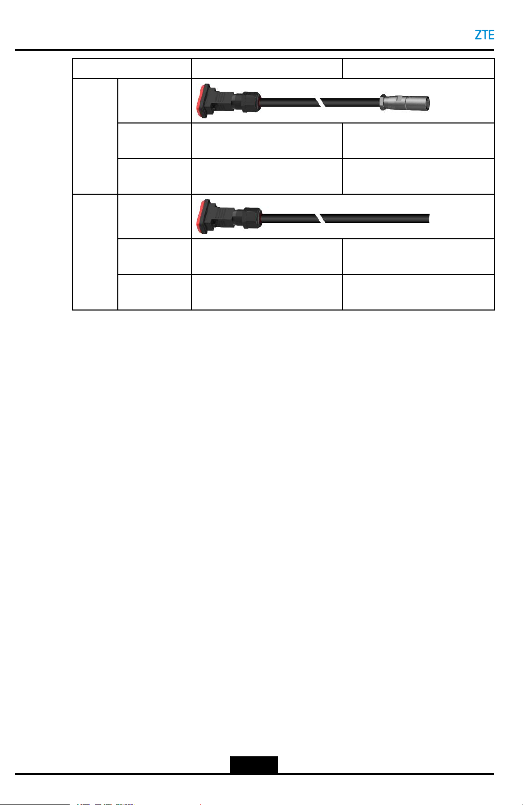
ItemLocalEquipmentInterconnectedEquipment
AISG
Cable
MON
Cable
CableConnectionDiagram
ExternalView
Connector
Type
Interconnected
Port
ExternalView
Connector
Type
Interconnected
Port
DB15connectorAISGconnector
LocalAISG/MONportofRRURCU'sAISGportofthetunable
antenna
DB15connectorNakedcables
LocalAISG/MONportofRRUExternalmonitoringdevice
5-2
SJ-20160405141455-003|2018-01-03(R1.3)ZTEProprietaryandCondential
Page 7
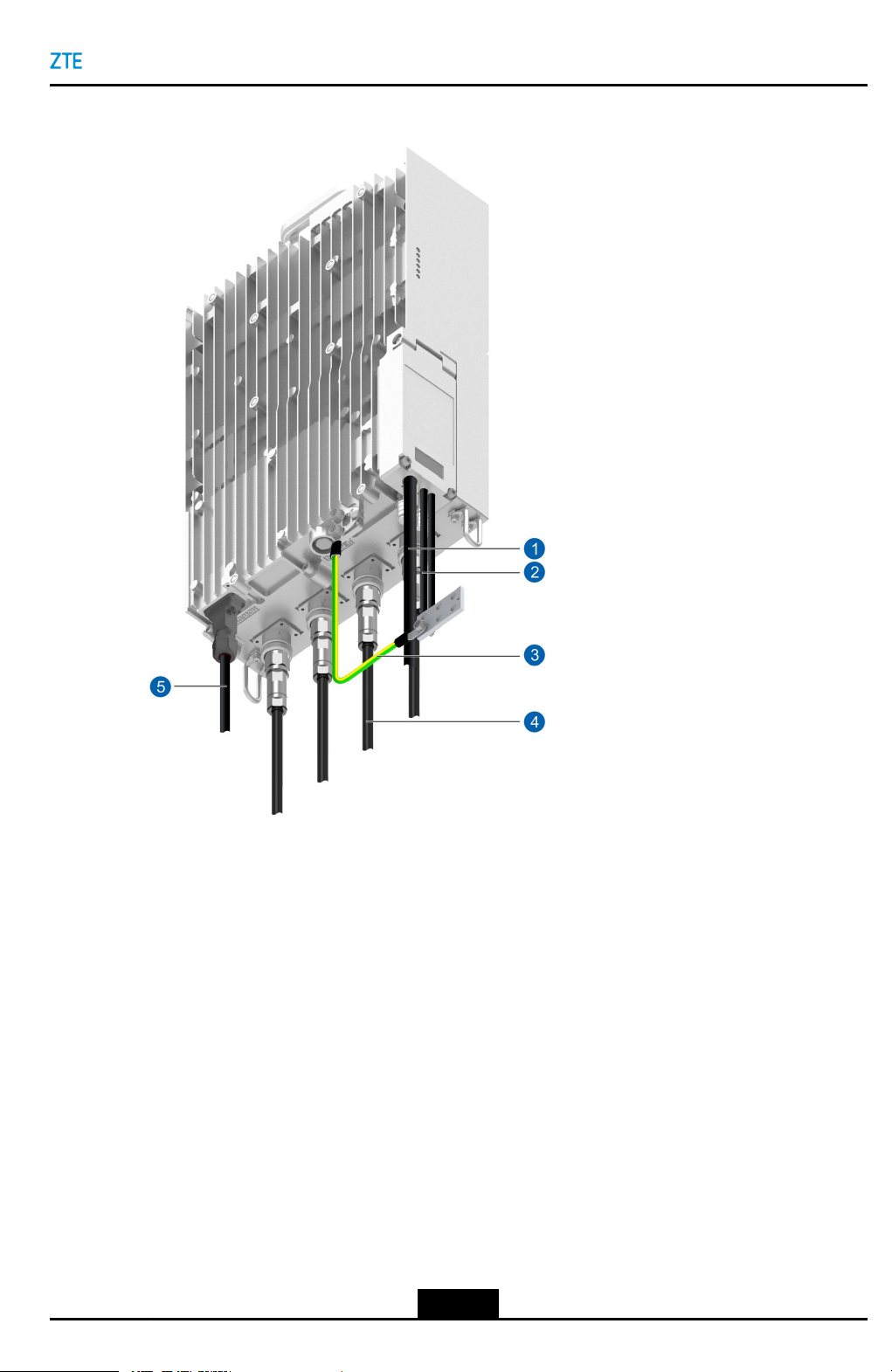
Figure5-1CableConnectionDiagram
Chapter5CableInstallation
1.DCpowercable
2.Opticalcable
3.Groundingcable
4.RFCable
TableofContents
InstallingtheProtectiveGroundingCable...................................................................
InstallingAntennaFeederCables...............................................................................
InstallingaMonitoringCable......................................................................................5-7
InstallingtheAISGCable...........................................................................................5-8
InstallingtheDCPowerInputCable.........................................................................5-10
InstallinganOpticalFiberCable...............................................................................5-15
UnusedInterfaceProtection.....................................................................................
5.1InstallingtheProtectiveGroundingCable
Thisproceduredescribeshowtoinstalltheprotectivegroundingcable.Theprotective
groundingcableisacopper-corecablewithacross-sectionalareaof16mm
5-3
5.AISG/MONCable
2
5-3
5-5
5-18
.
SJ-20160405141455-003|2018-01-03(R1.3)ZTEProprietaryandCondential
Page 8
ZXSDRR8854HardwareInstallation
Steps
1.Routetheprotectivegroundingcablefromtheindoororoutdoorgroundingbusbarto
theRRU.
2.CrimpanOTterminalattheRRUendoftheprotectivegroundingcable.
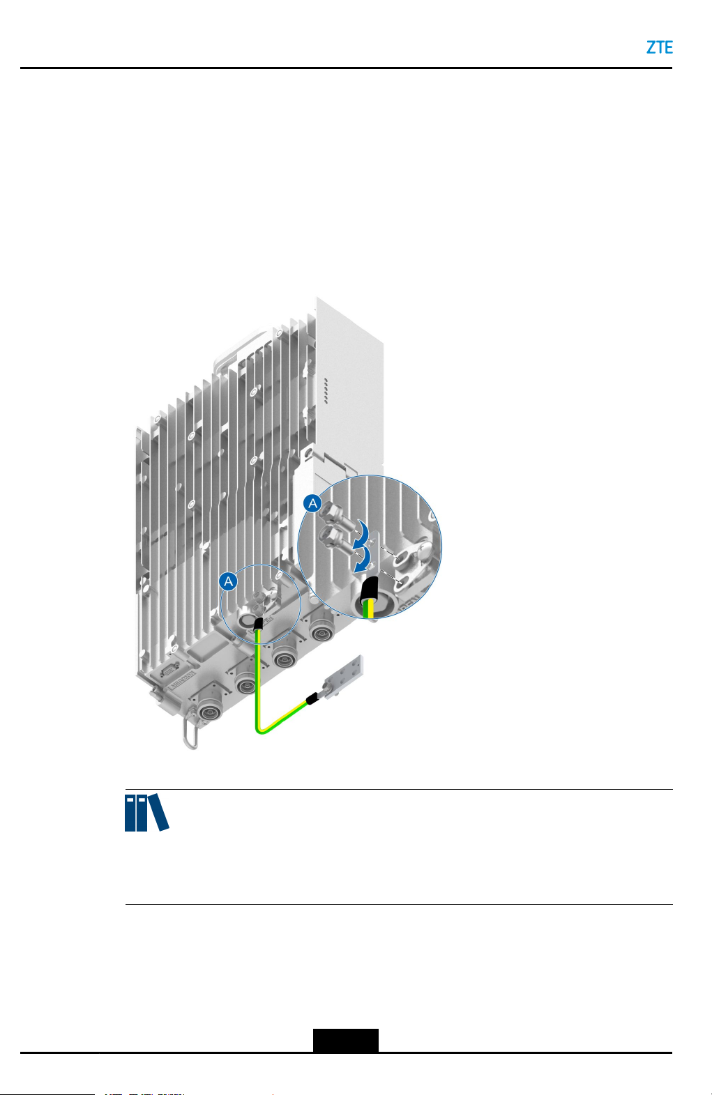
3.Fixoneendoftheprotectivegroundingcabletothegroundingscrewatthebottomof
theZXSDRR8854,seeFigure5-2.
Figure5-2ConnectingtheProtectiveGroundingCabletotheGroundingBusbar
(Directly)
Note:
About30cmofthecableshoulddroopfreelybeforethecableisroutedtothepoleor
cabletray.
4.RemovetherustonthegroundingbusbarandcrimpanOTterminalattheotherend
oftheprotectivegroundingcable.
5.Connecttheotherendoftheprotectivegroundingcabletothegroundingbusbarand
xittoabolt,seeFigure5-2.
5-4
SJ-20160405141455-003|2018-01-03(R1.3)ZTEProprietaryandCondential
Page 9
6.Bundleandlabelthecable.
7.Applyantirustpaintaroundthegroundingboltsonthegroundingbusbar.
–EndofSteps–
5.2InstallingAntennaFeederCables
Thisproceduredescribeshowtoinstallanantennafeedercable.
Therearetwotypesofantennafeedercables,antennafeedersandjumpers.Thedistance
betweentheRRUandtheantennadetermineshowtoinstallanantennafeedercable.For
details,refertoT able5-1.
Table5-1AntennaFeederCableInstallation
If...Then...
Chapter5CableInstallation
Thedistancebetweenthebasestationand
theantennaislessthanvemeters
Thedistancebetweenthebasestationand
theantennaisgreaterthanvemetersand
lessthan20meters
Afeederjumperisused.
A1/2"feederisused.
Steps
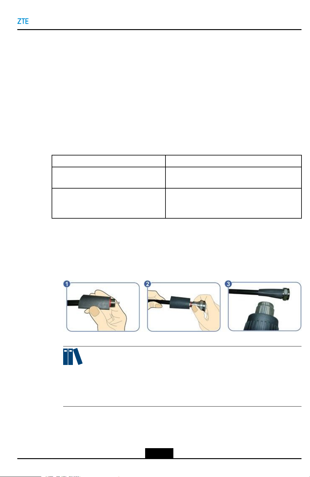
1.(Optional)Installaheat-shrinksleeveonthefeederconnectorifafeederconnector
needstobemadeonsite,seeFigure5-3.
Figure5-3MakingaFeederConnector
Note:
Ifthedistancebetweenthebasestationandtheantennaisgreaterthanvemeters,
bothfeedersandjumpersareusedforconnection.Inthiscase,feederconnectors
shouldbemadeonsite.
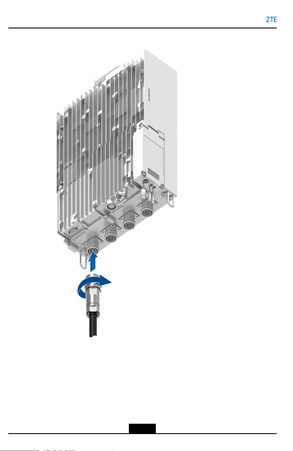
2.ConnectthefeedercabletotheantennafeederinterfaceontheRRUchassis,see
Figure5-4.
5-5
SJ-20160405141455-003|2018-01-03(R1.3)ZTEProprietaryandCondential
Page 10
ZXSDRR8854HardwareInstallation
Figure5-4InstallingAntennaFeederCables
3.Fastenthefeederconnectorclockwisewithaadjustablewrench.
4.Protectthecableconnectorsagainstwater.Fordetails,refertoChapter10
WaterproongOutdoorConnectors.
5.Laytheantennafeedercableontheantennasideandbinditwithblackcableties.
Thefeedershouldbelaidverticallyatleast200mmfromtheloweredgeofthedevice
whenitisledoutfromthebottomoftheRRUchassis.Itshouldnotbebent.The
minimumbendingradiusofthefeedershouldnotbelessthan20timesthefeeder's
radius.Itisprohibitedtocoilthefeeder.
5-6
SJ-20160405141455-003|2018-01-03(R1.3)ZTEProprietaryandCondential
Page 11
Chapter5CableInstallation
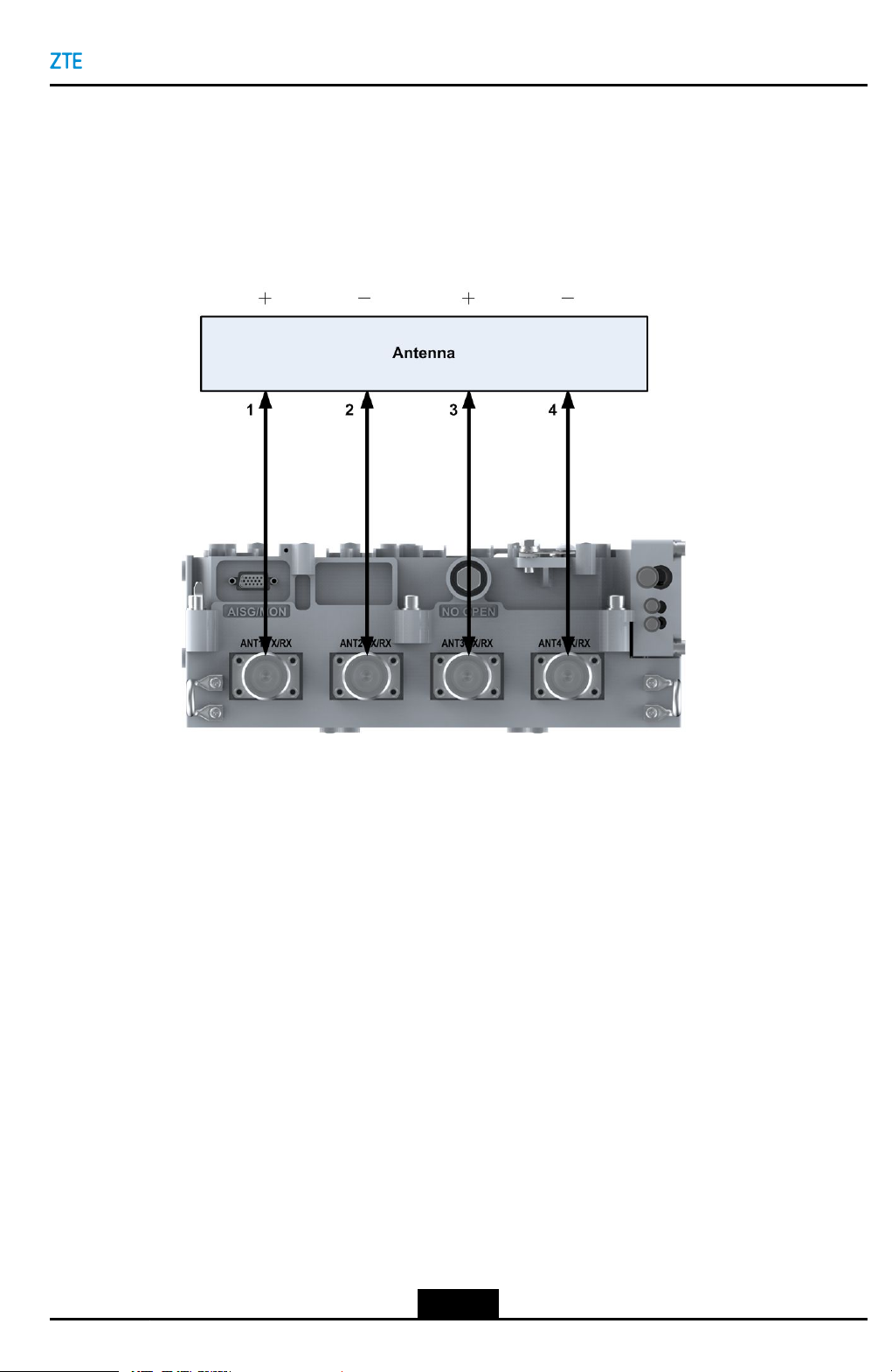
6.ConnecttheotherendofthefeedertotheANTinterfaceontheantenna.Take
waterproofmeasures.
7.Labelthefeedercablewithplastic.
8.Repeatsteps1through7toinstallotherfeedercables,seeFigure5-5.
Figure5-5ZXSDRR8854AntennaFeederConnectionDiagram
–EndofSteps–
5.3InstallingaMonitoringCable
Thisproceduredescribeshowtoinstallamonitoring(MON)cable.
Amonitoringcableisusedtoconnectthedrycontactinterfaceofanexternalmonitoring
device.
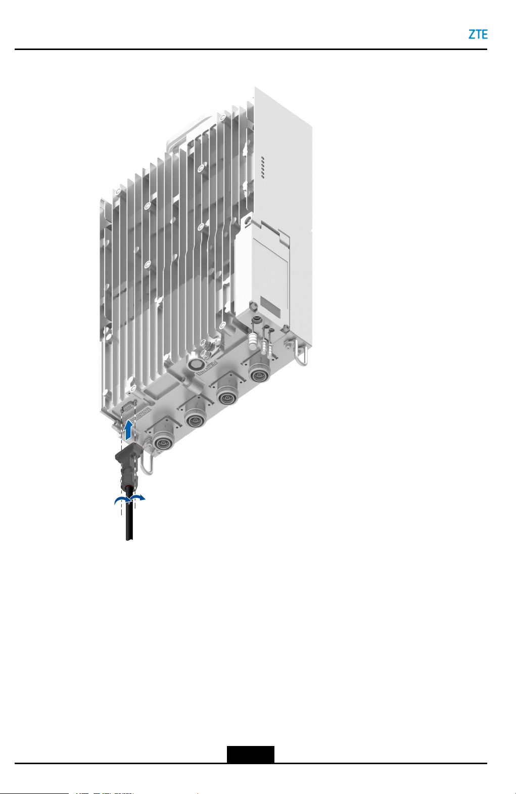
Steps
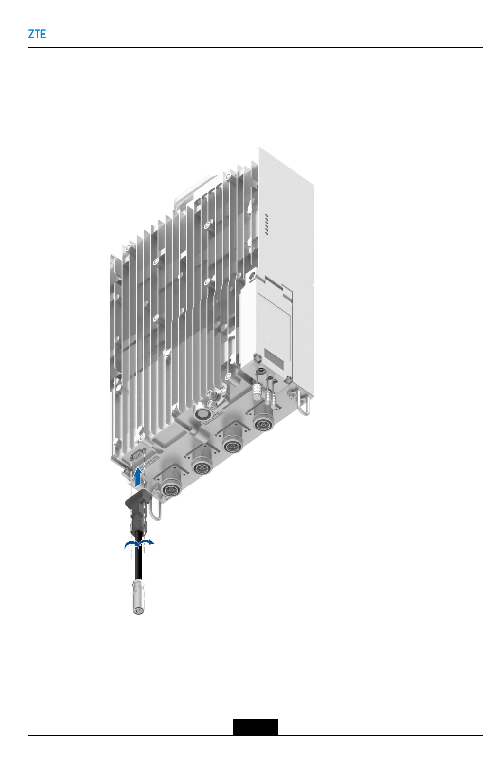
1.ConnectoneendofthemonitoringcabletotheAISG/MONinterfaceatthebottomof
theZXSDRR8854chassis,seeFigure5-6.
5-7
SJ-20160405141455-003|2018-01-03(R1.3)ZTEProprietaryandCondential
Page 12
ZXSDRR8854HardwareInstallation
Figure5-6InstallingaMonitoringCable
2.Connecttheotherendofthemonitoringcabletothedrycontactinterfaceofthe
externalmonitoringdevice.
3.Bundleandlabelthecable.
–EndofSteps–
5.4InstallingtheAISGCable
AnAISGcablebetweentheRFmoduleandanRETantennaisusedtotransmitthesignals
toorfromtheRETantenna.
5-8
SJ-20160405141455-003|2018-01-03(R1.3)ZTEProprietaryandCondential
Page 13
Chapter5CableInstallation
Steps
1.ConnectoneendoftheAISGinterfacecabletotheAISG/MONportontheZXSDR
R8854,seeFigure5-7.
Figure5-7InstallingtheAISGCable
2.ConnecttheotherendtotheAISGportontheRETantenna.
3.Bundleandlabelthecable.
–EndofSteps–
5-9
SJ-20160405141455-003|2018-01-03(R1.3)ZTEProprietaryandCondential
Page 14

ZXSDRR8854HardwareInstallation
5.5InstallingtheDCPowerInputCable
ThisproceduredescribeshowtoinstalltheDCpowerinputcable.
Context
TheZXSDRR8854DCpowerconnectorsupportspowercableswiththesectionalareaof
2
4mm
or6mm
usedbecausethedistancebetweentheZXSDRR8854andanexternalpowersupplyis
toolong,aDCjunctionbox(ODCPD1)isneededtoconnectthepowercabletothatwith
thesectionareaof4mm
refertoChapter9InstallingtheDCJunctionBox.
Steps
Openthemaintenancewindow
1.OpenthemaintenancewindowatthesideoftheZXSDRR8854,seeFigure5-8.
Figure5-8Openthemaintenancewindow
2
.Ifthepowercablewiththesectionalareaof10mm
2
or6mm
2
.ForhowtoinstalltheDCjunctionbox(ODCPD1),
2
or16mm
2
mustbe
MakingthePowerCableConnector
2.Followthemaintenancewindowdiagramtotailorthenakedshieldinglayer,child
cables,andnakedcoppercores.Sheathethetailoredcoopercoreswithtubular
terminalsandusethecrimpingplierstocrimpthesetubularterminals,seeFigure5-9.
5-10
SJ-20160405141455-003|2018-01-03(R1.3)ZTEProprietaryandCondential
Page 15

Chapter5CableInstallation
Figure5-9Wirestrippingthepowercable
3.Passthetubularterminalroundthetrimmedbarecoppercoreandcrimpthetubular
terminalwiththecrimpingpliers.
4.Conrmthepolarityofthepowerconnector'ssocketconnectedtothepowercable.
5.Usethescrewdrivertopressthemandrilluntilitcannotreboundandstuffthetubular
terminalsintothecrimpingtube,seeFigure5-10.Itisrequiredthattheleadingends
ofconductorsbecompletelyinsertedandhaveaclosecontactwiththeinnerbottom
oftheconnector'splug.
Figure5-10Insertthecrimpedtubularterminal
1.Button
2.Pull-tabinsulator
3.Mandrill
4.Crimpingtube
5.Shell
Note:
Standardassemblyrequiresthattubularterminalscannotbepushedforwardany
more.
6.Presstheredandbluebuttons(youmayusetoolslikescrewdriverbutarenotallowed
touseheavytoolslikehammer,ortheplugmaybemanaged).Themandrillejects
automatically.Ifyoupulltheconductorwithyourhandbutitdoesnotfalldown,it
indicatestheconductorisinstalledsecurely.
ConnectingPowerCableontheRRU
5-11
SJ-20160405141455-003|2018-01-03(R1.3)ZTEProprietaryandCondential
Page 16

ZXSDRR8854HardwareInstallation
7.Inthemaintenancewindow,usethecrossscrewdrivertounscrewthecrimpingclip
andremovethewaterproofplug,seeFigure5-11.
Figure5-1 1Unscrewthecrimpingclip
8.Inserttheconductorplugintothepowerportinsidethemaintenancewindow,see
Figure5-12.Pushtheplugforwardunityouhearthesoundof"click".Ifyoushake
theplugshellbutitdoesnotloosenorfalldown(youarenotallowedtopulltheplug's
pull-tabatthistime),itindicatesthattheplugisinstalledsecurelyandlockedclosely.
Figure5-12Insertthepowercable
5-12
SJ-20160405141455-003|2018-01-03(R1.3)ZTEProprietaryandCondential
Page 17

Chapter5CableInstallation
9.Usethecrimpingcliptocrimpthenakedpartoftheshieldinglayer,securethepower
cableattheoriginalwaterproofplug,andensurethatthenakedparthasaclosecontact
withthecrimpingclip.
Note:
Thetopedgeofthepowercable'sblackoutersheathshallalignwiththebottomedge
ofthecrimpingclipandshallnotbelowerthanthetopedgeofthecardslot.
10.Wrapthepowercablealongthepoleorcabletryanduseblacktiestobundleand
secureit.
IftheDCJunctionBox(ODCPD1)isequipped,refertoChapter9InstallingtheDC
JunctionBox.
EarthingthePowerCable
11.Connectthepowercabletothegroundingbusbarthroughagroundingkitbasedon
thelocationofthebasebandcabinetconnectedtotheotherendofthepowercable,
seeFigure5-13.
If...Then...
Thebasebandcabinetis
installedoutdoors
Thebasebandcabinetis
installedindoors
Connectthepowercabletotheoutdoorgroundingbusbarthroughthe
groundingkitbeforethecableisledintothecableinletholeofthe
outdoorcabinet.
Connectthepowercabletothegroundingbusbarthroughthegrounding
kitbeforethecableisledintotheroomandnearthefeederwindow.
lProtectthegroundingkitagainstwaterwiththe"1+3+3"solutionif
thepowercableisearthedbeforebeingledintothefeederwindow,
refertoChapter10WaterproongOutdoorConnectors.
lWindthegroundingkitwithtwolayersofinsulatingtapeifthe
powercableisearthedafterbeingledintothefeederwindow.The
groundingcableisconnectedtotheoutdoorgroundingbusbar.
5-13
SJ-20160405141455-003|2018-01-03(R1.3)ZTEProprietaryandCondential
Page 18

ZXSDRR8854HardwareInstallation
Figure5-13ConnectingthePowerCabletotheGroundingKit
Note:
Whenagroundingkitisused,theanglebetweenthegroundingcableandthepower
cablecannotbeupwardorbegreaterthan15degrees.Ifthegroundingkitisawayfrom
thefeederwindow,thegroundingcableshouldberoutedtowardthefeederwindow
alongthedownwarddirectionofthepowercable.
ConnectingthePowercableofthePowerSupplyEquipment
12.UseatubularterminaltomaketheconnectoroftheACpowercableattheBBUside,
andthenconnecttheACpowercabletotheDCoutputportoftheDCPD,seeFigure
5-14.
Figure5-14ConnectingthePowerCabletotheDCPD
5-14
SJ-20160405141455-003|2018-01-03(R1.3)ZTEProprietaryandCondential
Page 19

WhenyoumaketheconnectoroftheDCpowercable,cutofftheexposedshielded
layerafterstrippingoffthecableendandbindtheconnectorwithaheatshrinktube
orinsulatingtape.
13.Labelthepowercableatbothends.
–EndofSteps–
5.6InstallinganOpticalFiberCable
Thisproceduredescribeshowtoinstallanopticalbercable.
Steps
InstallingOpticalFiber
1.Openthecrimpingclipattheleftsideofthemaintenancewindow,seeFigure5-15.
Figure5-15Openthecrimpingclip
Chapter5CableInstallation
2.Removethecabletieatoneendofthecorrugatedpipemarkedas"RRU"byusingthe
diagonalpliers.
3.Removethewhitedustcapoftheopticalcableconnector,seeFigure5-16.
Figure5-16Removethewhitedustcap
1.Whitedustcap
5-15
SJ-20160405141455-003|2018-01-03(R1.3)ZTEProprietaryandCondential
Page 20

ZXSDRR8854HardwareInstallation
Note:
Donotremovethedustcapduringthestorage,transportation,androutingbefore
installation.
4.InserttheopticalmoduleintotheportsOPT1andOPT2oftheRRU.Alignthe
connectorwiththeopticalinterfacemodule,andinsertit.Whenyouhearthesound
of"bang",itindicatesthattheopticalcableconnectorisinstalledproperly,seeFigure
5-17.
Figure5-17Inserttheopticalcable
Note:
InthecaseofcascadedconnectionwithRRUs,useanopticalberforcascading
connectiontoconnecttheOPT2portofupper-levelRRUandtheOPT1portof
lower-levelRRU.
5.Securetheopticalcableatthecrimpingclipinthewiringcavity ,seeFigure5-18.
Inthecaseofoneopticalcable,installittotheoutgoingslotattherightsideanduse
awaterproofrubberplugtoblocktheotherslot.
5-16
SJ-20160405141455-003|2018-01-03(R1.3)ZTEProprietaryandCondential
Page 21

Figure5-18Securetheopticalcable
Chapter5CableInstallation
Note:
Inthemaintenancewindow,thereshallbeacertainarcbetweentheopticalcable
connectorandtheopticalcable.Thebendingradiusshallbelargerthan40mm.
6.Bundleandxtheopticalbercable.
Theoutdooropticalbercableshouldbelaidverticallyatleast200mmfromthelower
edgeofthedevicewhenitisledoutfromthebottomoftheRRUchassis.Theoptical
bercableshouldnotbebent.Theopticalbercableisthenxedontothepoleor
cabletray.Coiltheexcesspartoftheopticalbercableinadiameterof300mmto
400mmandthenbindthebercoiltoanappropriateposition(forexample,thewire
spoolontheBBU)withblackcableties.
7.Removethecabletieatoneendofthecorrugatedpipemarkedas"BBU"byusingthe
diagonalpliersandinstallittotheopticaljunctionboxorBBU.
8.Hangtheplasticlabelofopticalcable.
Closethemaintenancewindow
5-17
SJ-20160405141455-003|2018-01-03(R1.3)ZTEProprietaryandCondential
Page 22

ZXSDRR8854HardwareInstallation
9.Puttheremainingwaterproofplugsbacktotheiroriginalpositionsafterinstallingall
powercablesandbers.Closethepanelofmaintenancewindowandinstallthe
screwssecurelytoavoidwaterpenetration.
Thescrewsmustbefastenedtopreventwaterintrusion.
–EndofSteps–
5.7UnusedInterfaceProtection
Afterinstallingallcables,youneedtoprotectallunusedinterfacesontheZXSDRR8854.
Steps
Caution!
1.Checkanunusedinterface.
Checkwhetheranunusedinterfaceiscoveredwithadustproofcap.Ifnot,coverit
withadustproofcap.
2.Waterproofadustproofcap.
Wrapitwithablackdouble-layerultraviolet-prooftape:therstlayerfromtopdown,
thesecondlayerfrombottomupaccordingtothedirectionoftighteningtheinterface.
Makesurethatthewrappedtapeisushwiththelowersurfaceofthecap.Tighten
theedgeofthetapewithacabletie.
–EndofSteps–
5-18
SJ-20160405141455-003|2018-01-03(R1.3)ZTEProprietaryandCondential
Page 23

Chapter6
Post-InstallationCheck
ItemNo.Description
Equipment
Installation
Groundingand
Waterproong
CableRouting
1Installtheequipmentaccordingtothesitesurvey'sdesigndrawing
andensurethattheequipmentiswithin45°protectionofthe
lightningarrester.
2EnsurethattheinstallationsequenceofRRUpartsiscorrectand
installthemainequipmentsecurely.
3Ensurethatthecrimpingclipcloselypressesthenakedpartofthe
powercable'sshieldinglayerinthemaintenancewindow.
4EnsurethattheRRU,outdoorpowercable,andfeeder'sgrounding
pointcomplywithrelevantrequirements.
5Checktheantennafeeder's"1+3+3"waterproofprotectionand
ensurethatthemaintenancewindowissecurelyinstalledtoavoid
waterpenetration.
6Ensurethatthegroundingcard'scableisrouteddownwards,the
anglebetweenthegroundingleadandthefeederisnotlargerthan
15°.Removetherustontheterminalofthegroundingcablebefore
itisconnected.
7Ensurea20cmverticalcableroutingforRRUconnectorsand
antennaconnectors,andthattheprotectioncapsofallunusedRRU
connectorsaretightlyscrewed.
8Ensurethattheremainingantennafeedersarewoundinto"S"or"8"
shapeandtheremainingbersarewoundonthewirespooland
storedinaproperplace.
9Ensurethatawatertrapismadeforthecablethatisledintothe
equipmentroomandthelowestpointofthewatertrapis10to20cm
lowerthanthebottomedgeoftheinletportatthefeederwindow.
10Ensurethatoutdoorcablesarebundledbyusingblacktiesanda
sectionof2-3threads(3-5cm)isreserved.
11Ensurethatallcablesareconnectedsecurelyandlabelsarehanged
properlyatbothends.
12Ensurethatcablesareroutedproperlyandstraightly,withoutany
crossing,obviousups,downsandskews,orywire.
6-1
SJ-20160405141455-003|2018-01-03(R1.3)ZTEProprietaryandCondential
Page 24

Chapter7
Power-onInspection
TheZXSDRR8854ispoweredonafterinstallation.Ifanyerrorsarefound,youmust
troubleshoottheZXSDRR8854.
Context
Figure7-1showsthepower-oninspectionowoftheZXSDRR8854.
Figure7-1Power-onInspectionFlow
Steps
1.ConnectthepowersupplyequipmenttotheZXSDRR8854,orswitchontheaircircuit
breakerofthelightningprotectionbox.
7-1
SJ-20160405141455-003|2018-01-03(R1.3)ZTEProprietaryandCondential
Page 25

ZXSDRR8854HardwareInstallation
2.Powerthedeviceonat30-secondintervalsinorderofcellstoavoidcurrentsurge.
Checkwhetherornotthebercablesinacellareconnectedproperlythroughthe
indicatorsontheBBU.
–EndofSteps–
7-2
SJ-20160405141455-003|2018-01-03(R1.3)ZTEProprietaryandCondential
Page 26

Chapter8
Closure
Afterinstallation,performthefollowingoperations:
lPuttoolsinorder.
Putthetoolsusedduringtheinstallationbackinrightpositions.
lCollectunexpectedmaterials.
Collectunexpectedmaterialsandhandthemovertothecustomer.
lRemovewastematerials.
Removewastematerialsandcleantheenvironment.
lCompletetheinstallationreport.
Completetheinstallationreportandsubmittheinstallationreporttothepersonin
charge.
Ifthesiteisoperatingproperly ,notifytheoperationandmaintenanceengineersthat
theinstallationiscompleted.
8-1
SJ-20160405141455-003|2018-01-03(R1.3)ZTEProprietaryandCondential
Page 27

Chapter9
InstallingtheDCJunction
Box
ThisproceduredescribeshowtoinstalltheDCjunctionbox(ODCPD1).
TheZXSDRR8854DCpowerconnectorcannotbeconnectedtothepowercablewiththe
sectionalareaof10mm
2
mm
or16mm
externalpowersupplyistoolong,aDCjunctionbox(ODCPD1)isneededtoconnectthe
powercabletothatwiththesectionareaof4mm
2
mustbeusedbecausethedistancebetweentheZXSDRR8854andan
2
or16mm
Steps
InstallingtheODCPD1
1.FixthemountingbracketoftheODCPD1totheZXSDRR8854withfourscrews,see
Figure9-1.
2
.Ifthepowercablewiththesectionalareaof10
2
or6mm
2
.
Figure9-1FixingtheMountingBracketoftheODCPD1
9-1
SJ-20160405141455-003|2018-01-03(R1.3)ZTEProprietaryandCondential
Page 28

ZXSDRR8854HardwareInstallation
Caution!
TheODCPD1canbeinstalledbythebackortheside.Theinstallationpositionofit
shouldensurethatitcanbeopenedata90°angleatleastforeasymaintenance.
2.FixtheODCPD1tothemountingbracketwithtwoscrewsincludedwiththeODCPD1,
seeFigure9-2.
Figure9-2FixingtheODCPD1JunctionBox
InstallingthePowerCable
3.OpenthecoverplateoftheODCPD1,seeFigure9-3.
Figure9-3OpeningtheCoverPlateoftheODCPD1
9-2
SJ-20160405141455-003|2018-01-03(R1.3)ZTEProprietaryandCondential
Page 29

Chapter9InstallingtheDCJunctionBox
4.Maketheendsofthepowercableaccordingtothediagramontheinnersideofthe
coverplate,seeFigure9-4.CrimptheOTterminalsoftheexternalDCpowerinput
cableandtheDCpowercableconnectoroftheRRU.Thepartbetweentheshielded
layerandtheOTterminalmustbewrappedwithinsulationtape.
Figure9-4MakingaDCPowerCableConnector
5.PasstheDCpowercablethroughthewaterproofplugoftheODCPD1andxittothe
correctterminal,seeFigure9-5.
Figure9-5SecuringtheDCPowerCable
6.ClosethecoverplateoftheODCPD1andevenlytightenthesixwaterproofscrewson
thecoverplate,seeFigure9-6.
9-3
SJ-20160405141455-003|2018-01-03(R1.3)ZTEProprietaryandCondential
Page 30

ZXSDRR8854HardwareInstallation
Figure9-6ClosingtheCoverPlateoftheODCPD1
Caution!
Thescrewsmustbefastenedtopreventwaterintrusion.
7.ConnecttheotherendoftheDCpowercabletotheRRUandtheexternalpower
supplyequipmentrespectively.
8.Bundleandlabelthecable.
InstallingtheProtectiveGroundingCable
9.InstallthegroundingcablefromtheRRUtotheODCPD1,andthegroundingcable
fromtheODCPD1tothegroundingbar,seeFigure9-7.
9-4
SJ-20160405141455-003|2018-01-03(R1.3)ZTEProprietaryandCondential
Page 31

Chapter9InstallingtheDCJunctionBox
Figure9-7ConnectingtheProtectiveGroundingCabletotheGroundingBusbar
(ODCPD1)
–EndofSteps–
9-5
SJ-20160405141455-003|2018-01-03(R1.3)ZTEProprietaryandCondential
Page 32

Chapter10
WaterproongOutdoor
Connectors
Waterproongoutdoorconnectorsisa"1+3+3"process,thatis,wrappingonelayerof
PVCinsulatingtape,threelayersofwaterproofinsulatingtape,andthreelayersofPVC
insulatingtapearoundaconnector.
ThePVCinsulatingtapeisusedtopreventconnectorsfromdamage,ageing,andwater
ingress.
Steps
1.Cleanthecableconnectorandensurethatnodirtoroilstainexistsontheconnector.
2.Wrapalayerofelectricinsulationtape.
Afteracableconnectorisconnected,wraptheconnectorwiththeinsulationtape
downwardsinthedirectionthattheconnectoristightened,witheachroundcovering
halfofthepreviousround,seeFigure10-1.Ensurethatthepartabout10mmtothe
connectorendiswrappedwiththeinsulationtape.Whenwrappingtheconnector,
stretchthetapewithproperforce.
Figure10-1WrappingaLayerofElectricInsulationTape
3.Wrapthreelayersofwaterprooftape.
10-1
SJ-20160405141455-003|2018-01-03(R1.3)ZTEProprietaryandCondential
Page 33

ZXSDRR8854HardwareInstallation
Extendthewaterprooftapeuntilitswidthis50%to75%oftheoriginalwidth.
Wrapthreelayersofwaterprooftapeinthedirectionthattheconnectoristightened
topreventtheconnectorfromloosening.Wraptheconnectorupwardsfortherst
layer,downwardsforthesecondlayer,andthenupwardsagainforthethirdlayer ,
witheachroundcoveringaboutonethirdofthepreviousroundtopreventtheingress
ofrainwater,seeFigure10-2.Donotcutoffthetapebeforetheconnectorisfully
wrappedwiththreelayers.Ensurethatthepartwrappedwiththewaterprooftapeis
morethan20mminlength.
Afterwrappingtheconnectorwiththewaterprooftape,gripandpinchthewrappedpart
repeatedlywithbothhandstomakethewaterprooftapesecurelystucktothecable
andthecableconnector.
Figure10-2WrappingWaterproof/UVResistanceT ape
Caution!
Theoutermostlayeroftapeshallbeappliedfromthebottomuptoavoidwater
penetration.
4.WrapthreelayersofUVresistancetape.
WraptheconnectorwiththreelayersofUVresistancetapeinthesamedirection
ofwrappingwaterprooftape,seeFigure10-2.Payattentiontothefollowingwhen
wrappingacable:
lTheUVresistancetapeshouldbestretchedandwrappedwithproperforceto
preventitfrombeingstretchedtoomuch.
lTheupper-layertapecovers1/2thebottom-layertapeinlength.
lThewrappinglengthoftheUVresistancetapemustbe10mmlongerthanthat
ofthewaterprooftape.Wrapthreelayers.
Afterwrapthreelayers,gripandpinchboththeUVresistancetapeandwaterproof
tapetoensurethattheyaresecurelyadhered.
5.Securethetape'stwoends.
10-2
SJ-20160405141455-003|2018-01-03(R1.3)ZTEProprietaryandCondential
Page 34

Chapter10WaterproongOutdoorConnectors
Afterapplyingthetape,useblackultraviolet-prooftiestosecurelybundlethetape's
twoends,asshowninFigure10-3.Usethediagonalplierstocutofftheexcessive
tiesandreserveasectionof3mmatthemouth.Thisavoidstapeexpansionunder
hightemperature.
Figure10-3FixingBothEnds
–EndofSteps–
10-3
SJ-20160405141455-003|2018-01-03(R1.3)ZTEProprietaryandCondential
Page 35

Chapter11
InstallingaGantry
Thisproceduredescribeshowtoinstallagantry .
Steps
AssemblingaGantry
1.Fixtwopoststotwosidesofthebaseframewith12M5×16screws,seeFigure11-1.
Figure11-1AssemblingthePostandBaseFrame
2.FixthetopbeamtothepostswithfourM5×16screws,seeFigure1 1-2.
Figure11-2TighteningthePostandT opBeam
3.InstallthetwosupportingplateswithsixM5×16screwsrespectively ,seeFigure11-3.
11-1
SJ-20160405141455-003|2018-01-03(R1.3)ZTEProprietaryandCondential
Page 36

ZXSDRR8854HardwareInstallation
Figure11-3AssemblingtheSupportingPlate
DrillingHolesandInstallingExpansionBolts
4.Marktheholepositionswithadrillingtemplateandmarkerpen.
5.Drillholesatthemarkedpositionswithanelectricpercussiondrill(12mmindiameter)
andremovethechippingswithavacuumcleaner,seeFigure11-4.
Figure11-4DrillingHolesandInstallingExpansionBolts
FixingtheGantry
6.Fixthegantryinoneofthefollowingways:
If...Then...
InstallthegantryonaconcretebaseplateFixthegantrywithM10×100expansionbolts,seeFigure
11-5.
InstallthegantryinashelterFixthegantrywithM10×40self-tappingscrews,see
Figure11-6.
11-2
SJ-20160405141455-003|2018-01-03(R1.3)ZTEProprietaryandCondential
Page 37

Figure11-5FixingtheGantrytoaConcreteBaseplate
Chapter11InstallingaGantry
Figure11-6FixingtheGantrytoaShelter
–EndofSteps–
11-3
SJ-20160405141455-003|2018-01-03(R1.3)ZTEProprietaryandCondential
Page 38

Chapter12
LabelingSpecications
Labelsincludeindoorandoutdoorlabels.
lOutdoorlabelsarehangtagsthataredeliveredwiththedevice.
lIndoorlabelsaretheselfadhesivepaper-printedlabelsthatmayneedtobeproduced
atsiteifnecessary.
Labelsmustmeetthefollowingrequirements:
lThespecialpasterofZTECorporationmustbeusedforpaperlabels.
lContentsonrackrowlabelsandcolumnlabelsshouldmeettheengineeringdesign
requirements.
lBoardsshouldnotbelabeledandidentiersonaboardshouldnotbealtered.
lAlllabelsshouldbeattachedtofacethesamedirection.Thesidethatindicates
wherethecableisconnectedtoshouldfaceupwardortowardstheoperationand
maintenancepositionfortheconvenienceofbeingread.
lAllcablessuchasthepowercable,groundingcable,transmissioncable,andfeeder
shouldbelabeledatbothends.
lForopticalbers,networkcables,andtrunkcables,anindoorlabelshouldbepasted
20mmawayfromtheconnectoratbothendseach.
lOutdoorlabelsshouldbesecuredwithcabletiesatthesameheightanddirection.
12-1
SJ-20160405141455-003|2018-01-03(R1.3)ZTEProprietaryandCondential
Page 39

Figures
Figure1-1ZXSDRR8854InstallationFlow...............................................................1-1
Figure2-1DeviceHoisting........................................................................................
Figure2-2BindstheRRU.........................................................................................2-3
Figure2-3DoNotOpentheAirtightPart...................................................................2-4
Figure2-4DoNotInstallAnyPortUpwards..............................................................2-5
Figure2-5DoNotInstalltheRRUHorizontally.........................................................2-6
Figure2-6RecommendedSpaceforInstallingZXSDRR8854(inmm).....................2-7
Figure2-7MinimumSpaceforInstallingZXSDRR8854(inmm)..............................2-8
Figure4-1Wall-MountedInstallation.........................................................................
Figure4-2Pole-MountedInstallationofaSingleRRU..............................................4-2
Figure4-3Pole-MountedInstallationofTwoRRUs...................................................4-2
Figure4-4PoleHoop-MountedInstallationofaSingleRRU.....................................4-3
Figure4-5Gantry-MountedInstallation.....................................................................4-4
Figure4-6L-shapeSupportInstallation....................................................................4-5
Figure4-7InstallationPositionsofExpansionBolts..................................................
Figure4-8ExternalViewofanExpansionBolt..........................................................4-7
Figure4-9InstallinganExpansionBolt.....................................................................4-8
2-2
4-1
4-6
Figure4-10SecuringtheFixingClamp.....................................................................4-9
Figure4-11InstallingtheRRUSupport...................................................................4-10
Figure4-12InstallingtheRRUSupporttotheFixingClamp....................................4-10
Figure4-13SecuringtheRRU................................................................................
Figure4-14ChannelSteelPole-MountedInstallation..............................................4-12
Figure4-15AngleSteelPole-MountedInstallation..................................................4-12
Figure4-16AssemblingthePoleMountAssembly.................................................4-13
Figure4-17InstallingthePoleMountAssembly(1)................................................4-14
Figure4-18InstallingthePoleMountAssembly(2)................................................4-15
Figure4-19InstallingtheRRUSupport...................................................................4-15
Figure4-20InstallingtheRRUonthePoleMountAssembly..................................4-16
Figure4-21SecuringtheRRU................................................................................
Figure4-22AssemblingthePoleComponent........................................................4-18
Figure4-23InstallingthePoleComponent(1)........................................................4-18
Figure4-24InstallingthePoleComponent(2)........................................................4-19
4-11
4-16
I
SJ-20160405141455-003|2018-01-03(R1.3)ZTEProprietaryandCondential
Page 40

ZXSDRR8854HardwareInstallation
Figure4-25InstallingtheRRUSupport...................................................................4-20
Figure4-26InstallingtheRRUsonthePoleMountAssembly.................................
Figure4-27SecuringtheRRUs..............................................................................4-22
Figure4-28InstallingtheRRUSupport..................................................................4-24
Figure4-29InstallingtheFixingCliptothePole.....................................................4-26
Figure4-30MountingtheZXSDRR8854...............................................................4-26
Figure4-31TighteningtheCaptiveScrew..............................................................
Figure4-32InstallingtheAdapterPlate..................................................................4-29
Figure4-33SecuringtheFixingClamp...................................................................4-30
Figure4-34InstallingtheRRUSupport...................................................................4-31
Figure4-35InstallingtheRRUontheGantry..........................................................4-31
Figure4-36SecuringtheFixingClamp...................................................................4-34
Figure4-37InstallingtheRRUSupport...................................................................4-35
Figure4-38InstallingtheRRUontheL-shapeSupport..........................................
Figure5-1CableConnectionDiagram......................................................................5-3
Figure5-2ConnectingtheProtectiveGroundingCabletotheGroundingBusbar
(Directly).................................................................................................5-4
4-21
4-27
4-35
Figure5-3MakingaFeederConnector.....................................................................5-5
Figure5-4InstallingAntennaFeederCables............................................................5-6
Figure5-5ZXSDRR8854AntennaFeederConnectionDiagram..............................5-7
Figure5-6InstallingaMonitoringCable....................................................................5-8
Figure5-7InstallingtheAISGCable.........................................................................5-9
Figure5-8Openthemaintenancewindow..............................................................
5-10
Figure5-9Wirestrippingthepowercable...............................................................5-11
Figure5-10Insertthecrimpedtubularterminal.......................................................5-1 1
Figure5-11Unscrewthecrimpingclip....................................................................5-12
Figure5-12Insertthepowercable..........................................................................5-12
Figure5-13ConnectingthePowerCabletotheGroundingKit...............................5-14
Figure5-14ConnectingthePowerCabletotheDCPD...........................................5-14
Figure5-15Openthecrimpingclip.........................................................................5-15
Figure5-16Removethewhitedustcap..................................................................
5-15
Figure5-17Inserttheopticalcable.........................................................................5-16
Figure5-18Securetheopticalcable.......................................................................5-17
Figure7-1Power-onInspectionFlow........................................................................7-1
Figure9-1FixingtheMountingBracketoftheODCPD1...........................................9-1
Figure9-2FixingtheODCPD1JunctionBox............................................................9-2
II
SJ-20160405141455-003|2018-01-03(R1.3)ZTEProprietaryandCondential
Page 41

Figure9-3OpeningtheCoverPlateoftheODCPD1................................................9-2
Figures
Figure9-4MakingaDCPowerCableConnector......................................................
Figure9-5SecuringtheDCPowerCable.................................................................9-3
Figure9-6ClosingtheCoverPlateoftheODCPD1..................................................9-4
Figure9-7ConnectingtheProtectiveGroundingCabletotheGroundingBusbar
(ODCPD1)..............................................................................................9-5
Figure10-1WrappingaLayerofElectricInsulationT ape........................................10-1
Figure10-2WrappingWaterproof/UVResistanceT ape..........................................10-2
Figure10-3FixingBothEnds..................................................................................10-3
Figure11-1AssemblingthePostandBaseFrame..................................................11-1
Figure11-2TighteningthePostandT opBeam.......................................................
Figure11-3AssemblingtheSupportingPlate..........................................................11-2
Figure11-4DrillingHolesandInstallingExpansionBolts........................................11-2
Figure11-5FixingtheGantrytoaConcreteBaseplate...........................................11-3
Figure11-6FixingtheGantrytoaShelter...............................................................11-3
9-3
11-1
III
SJ-20160405141455-003|2018-01-03(R1.3)ZTEProprietaryandCondential
Page 42

Tables
Table2-1InstrumentsandMetersList......................................................................2-6
Table4-1AccessoriesforWall-MountedInstallation..................................................
Table4-2AccessoriesforSingle-RRUPole-MountedInstallation............................4-12
Table4-3AccessoriesforTwo-RRUPole-MountedInstallation...............................4-17
Table4-4InstallationAccessoriesofPoleHoop-MountedInstallationModeofa
SingleRRU...........................................................................................4-23
Table4-5AccessoriesforGantry-MountedInstallation............................................4-28
Table4-6AccessoriesforL-shapeSupportInstallation...........................................4-33
Table5-1AntennaFeederCableInstallation.............................................................5-5
4-6
V
SJ-20160405141455-003|2018-01-03(R1.3)ZTEProprietaryandCondential
Page 43

Glossary
AISG
-AntennaInterfaceStandardsGroup
BBU
-BaseBandUnit
DC
-DirectCurrent
MON
-Monitor
PVC
-PolyvinylChloride
RRU
-RemoteRadioUnit
VII
SJ-20160405141455-003|2018-01-03(R1.3)ZTEProprietaryandCondential
 Loading...