

Page 1

ZXSDRR8854
MacroRadioRemoteUnit
HardwareInstallation
Version:1.0
ZTECORPORATION
No.55,Hi-techRoadSouth,ShenZhen,P .R.China
Postcode:518057
Tel:+86-755-26771900
Fax:+86-755-26770801
URL:http://support.zte.com.cn
E-mail:800@zte.com.cn
Page 2

LEGALINFORMATION
Copyright©2017ZTECORPORATION.
Thecontentsofthisdocumentareprotectedbycopyrightlawsandinternationaltreaties.Anyreproductionor
distributionofthisdocumentoranyportionofthisdocument,inanyformbyanymeans,withoutthepriorwritten
consentofZTECORPORATIONisprohibited.Additionally,thecontentsofthisdocumentareprotectedby
contractualcondentialityobligations.
Allcompany,brandandproductnamesaretradeorservicemarks,orregisteredtradeorservicemarks,ofZTE
CORPORATIONoroftheirrespectiveowners.
Thisdocumentisprovided“asis”,andallexpress,implied,orstatutorywarranties,representationsorconditions
aredisclaimed,includingwithoutlimitationanyimpliedwarrantyofmerchantability,tnessforaparticularpurpose,
titleornon-infringement.ZTECORPORATIONanditslicensorsshallnotbeliablefordamagesresultingfromthe
useoforrelianceontheinformationcontainedherein.
ZTECORPORA TIONoritslicensorsmayhavecurrentorpendingintellectualpropertyrightsorapplications
coveringthesubjectmatterofthisdocument.ExceptasexpresslyprovidedinanywrittenlicensebetweenZTE
CORPORATIONanditslicensee,theuserofthisdocumentshallnotacquireanylicensetothesubjectmatter
herein.
ZTECORPORA TIONreservestherighttoupgradeormaketechnicalchangetothisproductwithoutfurthernotice.
UsersmayvisittheZTEtechnicalsupportwebsitehttp://support.zte.com.cntoinquireforrelatedinformation.
TheultimaterighttointerpretthisproductresidesinZTECORPORATION.
RevisionHistory
RevisionNo.RevisionDateRevisionReason
R1.32018–01–03lUpdatedthewaytobundletheRRUin2.2Precautionsfor
DeviceHoisting.
lUpdatedthefollowingsections:4RRUInstallation,4.1
InstallinganRRUonaWall,4.2InstallingaSingleRRUon
aPole,4.3InstallingTwoRRUsonaPole,4.5Installing
anRRUonaGantry ,4.6InstallinganRRUonaL-shape
Support.
lAddednewsection:4.4InstallingaSingleRRUinPole
Hoop-MountedMode.
R1.22016-07-30AddedscaldprotectioninformationinSection2.3Installation
Precautions
R1.12016-06-20lUpdated“5.2InstallingAntennaFeederCables”
lUpdated“5.5InstallingtheDCPowerInputCable”
lAdded“AppendixAInstallingtheDCJunctionBox”
R1.02016-04-06Firstedition
SerialNumber:SJ-20160405141455-003
PublishingDate:2018-01-03(R1.3)
SJ-20160405141455-003|2018-01-03(R1.3)ZTEProprietaryandCondential
Page 3

Contents
AboutThisManual.........................................................................................I
Chapter1InstallationFlow........................................................................1-1
Chapter2InstallationPreparations..........................................................
2.1PrecautionsforDeviceTransport.........................................................................2-1
2.2PrecautionsforDeviceHoisting...........................................................................
2.3InstallationPrecautions.......................................................................................2-4
2.4InstrumentsandMetersList................................................................................
2.5InstallationSpaceRequirement...........................................................................2-7
Chapter3UnpackingandInspection.......................................................3-1
Chapter4RRUInstallation........................................................................
4.1InstallinganRRUonaWall................................................................................4-5
4.2InstallingaSingleRRUonaPole.......................................................................4-11
4.3InstallingTwoRRUsonaPole..........................................................................4-17
4.4InstallingaSingleRRUinPoleHoop-MountedMode..........................................4-22
4.5InstallinganRRUonaGantry...........................................................................4-27
4.6InstallinganRRUonaL-shapeSupport............................................................4-32
Chapter5CableInstallation......................................................................
5.1InstallingtheProtectiveGroundingCable.............................................................5-3
2-1
2-1
2-6
4-1
5-1
5.2InstallingAntennaFeederCables........................................................................5-5
5.3InstallingaMonitoringCable...............................................................................5-7
5.4InstallingtheAISGCable....................................................................................5-8
5.5InstallingtheDCPowerInputCable..................................................................5-10
5.6InstallinganOpticalFiberCable........................................................................5-15
5.7UnusedInterfaceProtection..............................................................................5-18
Chapter6Post-InstallationCheck............................................................6-1
Chapter7Power-onInspection.................................................................
Chapter8Closure.......................................................................................8-1
Chapter9InstallingtheDCJunctionBox................................................9-1
Chapter10WaterproongOutdoorConnectors...................................10-1
Chapter11InstallingaGantry.................................................................11-1
Chapter12LabelingSpecications........................................................12-1
I
7-1
SJ-20160405141455-003|2018-01-03(R1.3)ZTEProprietaryandCondential
Page 4

Figures.............................................................................................................I
Tables.............................................................................................................V
Glossary.......................................................................................................VII
II
SJ-20160405141455-003|2018-01-03(R1.3)ZTEProprietaryandCondential
Page 5

AboutThisManual
Purpose
ThismanualdescribeshowtoinstalltheZXSDRR8854.
IntendedAudience
Thismanualisintendedfor:
lInstallationengineers
lMaintenanceengineers
WhatIsinThisManual
Thismanualcontainsthefollowingchapters.
Chapter1,InstallationFlowDescribestheinstallationowoftheZXSDRR8854.
Chapter2,Installation
Preparations
Chapter3,Unpackingand
Inspection
Chapter4,RRUInstallationDescribeshowtoinstalltheZXSDRR8854.
Chapter5,CableInstallationDescribeshowtoinstallexternalcablesfortheZXSDRR8854.
Chapter6,Post-Installation
Check
Chapter7,Power-onInspectionDescribeshowtoinspecttheoperationoftheZXSDRR8854after
Chapter8,ClosureDescribestheoperationsthatneedtobeimplementedafterall
Chapter9,InstallingtheDC
JunctionBox
Chapter10,Waterproong
OutdoorConnectors
Chapter11,InstallingaGantryDescribeshowtoinstallagantry.
Describespreparationsbeforeequipmentinstallation.
Describesprecautionsaboutequipmentunpackingandinspection.
Describeshowtoinspecthardwareinstallation.
theZXSDRR8854ispoweredon.
hardwarecomponentsareinstalled.
DescribeshowtoinstalltheDCjunctionbox.
Describestheprocedureforconnectingandwaterproongthe
outdoorconnectors.
Chapter12,Labeling
Specications
Describeshowtocorrectlyuseoutdoorandindoorlabels.
Conventions
Thismanualusesthefollowingconventions.
ItalicsVariablesincommands.Itmayalsorefertootherrelatedmanualsanddocuments.
I
SJ-20160405141455-003|2018-01-03(R1.3)ZTEProprietaryandCondential
Page 6

BoldMenus,menuoptions,functionnames,inputelds,optionbuttonnames,checkboxes,
drop-downlists,dialogboxnames,windownames,parameters,andcommands.
Constant
width
[]Optionalparameters.
{}Mandatoryparameters.
|Separatesindividualparametersinaseriesofparameters.
Textthatyoutype,programcodes,lenames,directorynames,andfunctionnames.
Danger:indicatesanimminentlyhazardoussituation.Failuretocomplywillresultin
deathorseriouspersonalinjury.
Warning:indicatesapotentiallyhazardoussituation.Failuretocomplycanresultin
deathorseriouspersonalinjury.
Caution:indicatesapotentiallyhazardoussituation.Failuretocomplycanresultin
moderateorminorpersonalinjury.
Notice:indicatesequipmentorenvironmentsafetyinformation.Failuretocomply
canresultinequipmentdamage,dataloss,equipmentperformancedegradation,
environmentalcontamination,orotherunpredictableresults.
Note:providesadditionalinformationaboutatopic.
II
SJ-20160405141455-003|2018-01-03(R1.3)ZTEProprietaryandCondential
Page 7

Chapter1
InstallationFlow
FortheinstallationowoftheZXSDRR8854,seeFigure1-1.
Figure1-1ZXSDRR8854InstallationFlow
1-1
SJ-20160405141455-003|2018-01-03(R1.3)ZTEProprietaryandCondential
Page 8

Chapter2
InstallationPreparations
BeforeinstallingtheZXSDRR8854,installationengineersshouldchecktheinstallation
environmentanddeliveranEnvironmentAcceptanceReport.
Installationparts,tools,andinstrumentsshouldbeavailablebeforeinstallation.
Caution!
TheZXSDRR8854mustbepoweredonwithin24hoursafteritisunpacked.
Thepower-offdurationoftheZXSDRR8854mustnotbegreaterthan24hoursduring
maintenance.
TableofContents
PrecautionsforDeviceTransport...............................................................................
PrecautionsforDeviceHoisting..................................................................................2-1
InstallationPrecautions..............................................................................................2-4
InstrumentsandMetersList.......................................................................................
InstallationSpaceRequirement..................................................................................2-7
2.1PrecautionsforDeviceTransport
lAdevicemustbetransportedwiththeouterpackingcontainertoprotectthedevice
fromscratches.
lAfterthepackingcontainerisremovedonsite,thedevicemustbeprotectedwhen
youmoveorstoreit.Forexample,whenadeviceisstoredtemporarily,cushioning
materialsmustbeputunderthebottomofthedevicetoavoiddirectcontactwiththe
groundandsurroundingobjects.
lWhenyoutransportadevice,cushioningmaterialssuchasfoamedplasticand
paperboardmustbeusedtoprotectthedevicefromscratches.Whenyoulifta
deviceup,thedevicemustbedraggedproperlytoavoidcollisionwithotherobjects.
2.2PrecautionsforDeviceHoisting
2-1
2-6
TheinformationprovidedisusedforreferencewhenitisnecessarytohoisttheRRU.
1.InstallerAonthetowersecuresthexedpulleytothetower,andpassesthehoisting
ropethroughthexedpulleydowntotheground,seeFigure2-1.
2-1
SJ-20160405141455-003|2018-01-03(R1.3)ZTEProprietaryandCondential
Page 9

ZXSDRR8854HardwareInstallation
Figure2-1DeviceHoisting
1.Fixedpulley2.Haulingrope3.Hoistingrope
Caution!
InstallerAonthetowercannotloosenthexedropeuntilheconrmsthatthedevice
issecurelyplacedonthetowerplatform.
2.InstallerConthegroundbindstheRRUtightly ,seeFigure2-2.
2-2
SJ-20160405141455-003|2018-01-03(R1.3)ZTEProprietaryandCondential
Page 10

Figure2-2BindstheRRU
Chapter2InstallationPreparations
Note:
Passthehoistingropethroughthehandleandhoistinghole.
PassthehaulingropethroughthehandleonthetopoftheRRU,avoidingtheRRU
mountingbracket,andgettheropestuckbetweenthegroundingpointandthe
protectionblockatthebottomoftheRRU.BundletheRRUwiththeropebetween
thegroundingpointandtheprotectionblockatthebottomoftheRRU,ensuringthat
theRRUisbundledrmly.
3.InstallerBonthegrounddragsthehoistingropedownwards.Atthesametime,
installerCpullsthehaulingropeoutwardstoprotectthedevicefromcollidingwith
thetowerwhenthedevicereachesthemountingplatform,seeFigure2-1.
4.Lifttheproperly-packedengineeringmaterialsusedfortowermountingontothetower
inthemannermentionedabove.
2-3
SJ-20160405141455-003|2018-01-03(R1.3)ZTEProprietaryandCondential
Page 11

ZXSDRR8854HardwareInstallation
2.3InstallationPrecautions
Caution!
Neverlifttheengineeringmaterialsbybindingthemdirectlytothehoistingrepe.
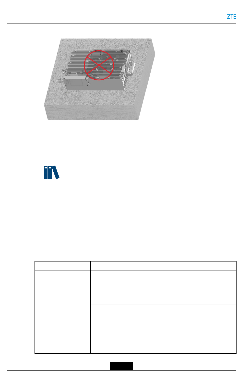
1.Donotopentheequipment'sairtightpart,seeFigure2-3.
Figure2-3DoNotOpentheAirtightPart
2.TheRRUboxhasalayerofrustproofpaintthatprotectsitfrombeingscratchedduring
transportationandinstallation.
3.Donotinstallanyportupwards,seeFigure2-4.
2-4
SJ-20160405141455-003|2018-01-03(R1.3)ZTEProprietaryandCondential
Page 12

Figure2-4DoNotInstallAnyPortUpwards
Chapter2InstallationPreparations
4.Donotusethehorizontalinstallationmode,seeFigure2-5.
2-5
SJ-20160405141455-003|2018-01-03(R1.3)ZTEProprietaryandCondential
Page 13
ZXSDRR8854HardwareInstallation
Figure2-5DoNotInstalltheRRUHorizontally
5.Thedevicemustbeinstalledinaspecialareawhereprotectionmeasuresaretaken
andonlymaintenancepersonnelunderthecontroloftheresponsibleunitcanenter.
6.Beforemaintainingthedevice,poweroffthedevicetocoolitdown.Thedevicecannot
beoperateduntilthecasetemperatureisbelow70°Ctoavoidscald.
Note:
Thedurationforcoolingthedevicedownafterpower-offcannotbelongerthanthe
maintenancetime.Thedurationforwaitingforthecooldownshouldbedetermined
throughtesting.
2.4InstrumentsandMetersList
Table2-1liststheinstrumentsandmetersrequiredforinstallingtheZXSDRR8854.
Table2-1InstrumentsandMetersList
ItemList
General-purpose
instruments
Measuringandrulinginstruments:
5msteeltape,1mruler,gradienter,marker,drillingtemplate
Drillinginstruments:
Electricpercussiondrill(auxiliarydrillbits)andvacuumcleaner
Tighteninginstruments:
Crossscrewdrivers(M3–M6),Allenkey(M5–M6),adjustablewrench
(M10),andtorquewrench
Smallinstruments:
Snipe-nosepliers,diagonalpliers,vices,le,hacksaw,andhydraulic
pressurepliers
2-6
SJ-20160405141455-003|2018-01-03(R1.3)ZTEProprietaryandCondential
Page 14

ItemList
Chapter2InstallationPreparations
Auxiliaryinstruments:
Chainwheel,Ladder,Rope,scissors,slip-proofgloves,safetyhelmet,
connectorcard,paintbrush,andhotairblower
Special-purpose
instruments
MetersDigitalmultimeter,VSWRtester,earthresistancetester,basestation
2.5InstallationSpaceRequirement
Figure2-6showstherecommendedspaceforinstallingZXSDRR8854.
Figure2-6RecommendedSpaceforInstallingZXSDRR8854(inmm)
Multi-functionalcrimpingpliersandfeederconnectorknife
tester,compass,eldstrengthtester(forspecialpurpose),andspectrum
analyzer(forspecialpurpose)
Figure2-7showstheminimumspaceforinstallingZXSDRR8854.
2-7
SJ-20160405141455-003|2018-01-03(R1.3)ZTEProprietaryandCondential
Page 15

ZXSDRR8854HardwareInstallation
Figure2-7MinimumSpaceforInstallingZXSDRR8854(inmm)
2-8
SJ-20160405141455-003|2018-01-03(R1.3)ZTEProprietaryandCondential
Page 16

Chapter3
UnpackingandInspection
CountingGoods
lVerifythatthepackagingboxesareintact.Ifanydamageisfound,contactthe
transportcompanyimmediately.
lUnpacktheboxesandverifythatthegoodsareconsistentwiththeinspection
checklist.
lVerifythatthechassisisingoodconditionwithoutscratches,peelingpaint,blisters,
orstains.
lVerifythattheaccessoriesrequiredfortheinstallationarecorrectandcomplete.
EquipmentHandover
Aftertheexaminationofgoods,theengineeringsupervisorandtheoperator's
representativeshouldsigntheUnpackingAcceptanceReport.TheUnpackingAcceptance
Reportismadeinduplicate,andkeptbybothparties.Theengineeringsupervisormust
sendtheUnpackingAcceptanceReportbacktotherepresentativeofcewithinseven
daysforarchiving.
3-1
SJ-20160405141455-003|2018-01-03(R1.3)ZTEProprietaryandCondential
Page 17
Chapter4
RRUInstallation
TheZXSDRR8854canbeinstalledinthefollowingways:
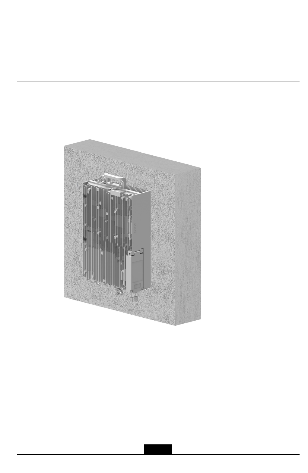
lWall-mountedinstallation,seeFigure4-1.
Figure4-1Wall-MountedInstallation
lPole-mountedinstallation,seeFigure4-2,Figure4-3andFigure4-4.
4-1
SJ-20160405141455-003|2018-01-03(R1.3)ZTEProprietaryandCondential
Page 18

ZXSDRR8854HardwareInstallation
Figure4-2Pole-MountedInstallationofaSingleRRU
Figure4-3Pole-MountedInstallationofT woRRUs
4-2
SJ-20160405141455-003|2018-01-03(R1.3)ZTEProprietaryandCondential
Page 19

Figure4-4PoleHoop-MountedInstallationofaSingleRRU
Chapter4RRUInstallation
lGantry-mountedinstallation,seeFigure4-5.
4-3
SJ-20160405141455-003|2018-01-03(R1.3)ZTEProprietaryandCondential
Page 20

ZXSDRR8854HardwareInstallation
Figure4-5Gantry-MountedInstallation
lL-shapesupportinstallation,seeFigure4-6.
4-4
SJ-20160405141455-003|2018-01-03(R1.3)ZTEProprietaryandCondential
Page 21

Figure4-6L-shapeSupportInstallation
Chapter4RRUInstallation
TableofContents
InstallinganRRUonaWall........................................................................................4-5
InstallingaSingleRRUonaPole.............................................................................4-11
InstallingTwoRRUsonaPole.................................................................................4-17
InstallingaSingleRRUinPoleHoop-MountedMode...............................................4-22
InstallinganRRUonaGantry..................................................................................4-27
InstallinganRRUonaL-shapeSupport...................................................................4-32
4.1InstallinganRRUonaWall
AnRRUcanbeinstalledonawallwhenusedindoors,outdoors,orinahigh-speedrail
scenario.
ThisproceduredescribeshowtoinstalltheZXSDRR8854onawall.
Context
ForadescriptionoftheaccessoriesusedforinstallinganRRUonawall,refertoT able
4-1.
4-5
SJ-20160405141455-003|2018-01-03(R1.3)ZTEProprietaryandCondential
Page 22

ZXSDRR8854HardwareInstallation
Table4-1AccessoriesforWall-MountedInstallation
NameExternalView
Fixingclamp
RRUsupport
Steps
DrillingaHole
1.Marktheholepositionsonthewallwithadrillingtemplate,seeFigure4-7.
Figure4-7InstallationPositionsofExpansionBolts
4-6
SJ-20160405141455-003|2018-01-03(R1.3)ZTEProprietaryandCondential
Page 23

Chapter4RRUInstallation
2.Drillan80mm-deepholeinthemarkedpositionwithaφ12drillbit.Makesurethat
theholeisverticaltothewallandremovedustwithavacuumcleanerduringdrilling.
InstallinganExpansionBolt
3.Installanexpansionbolt,seeFigure4-9.
Figure4-8showsanexternalviewofanexpansionbolt.
Figure4-8ExternalViewofanExpansionBolt
1.Nut
2.Springwasher
3.Flatwasher
4.Bolt
5.Expansiontube
4-7
SJ-20160405141455-003|2018-01-03(R1.3)ZTEProprietaryandCondential
Page 24

ZXSDRR8854HardwareInstallation
Figure4-9InstallinganExpansionBolt
StepDescription
aSlightlyturntheexpansionboltclockwisetopreventitfrommovingfreely.
bBeforehammeringtheexpansionboltwithaclawhammer,takeanutwith
thesamespecicationsasthenutofthisexpansionboltandturnthenut
untilthetopofnutisushwiththatoftheexpansionbolttoavoiddamaging
thethreadduringhammering.
cHammertheexpansionboltintotheinstallationholewithaclawhammer.
dFastenthenutneartheexpansiontubeclockwisetoallowtheexpansionbolt
tofullyexpand.
eLoosenthenutcounterclockwiseandremovethenut,springwasher ,andat
washerinturnforuseduringsubsequentinstallation.
InstallingtheFixingClamp
4.Securethexingclamptothewallwithatorqueof40N•m,withthenuts,spring
washers,andatwashersremovedfromtheexpansionbolts,seeFigure4-10.
4-8
SJ-20160405141455-003|2018-01-03(R1.3)ZTEProprietaryandCondential
Page 25

Figure4-10SecuringtheFixingClamp
Chapter4RRUInstallation
1.Nut2.Springwasher3.Flatwasher
Note:
Theyellowarrowonthexingclampshouldpointupwardsduringinstallation.
SecuringtheRRU
5.FixtheRRUsupporttothebackoftheRRUwithfourM6screwswithatorqueof8
N•m,seeFigure4-11.
4-9
SJ-20160405141455-003|2018-01-03(R1.3)ZTEProprietaryandCondential
Page 26

ZXSDRR8854HardwareInstallation
Figure4-11InstallingtheRRUSupport
6.InstalltheRRUsupporttothexingclamp,seeFigure4-12.
Figure4-12InstallingtheRRUSupporttotheFixingClamp
7.TightenthecaptivescrewonthetopoftheRRUsupportwithanM6Allenhexwrench,
seeFigure4-13.
4-10
SJ-20160405141455-003|2018-01-03(R1.3)ZTEProprietaryandCondential
Page 27

Figure4-13SecuringtheRRU
Chapter4RRUInstallation
–EndofSteps–
4.2InstallingaSingleRRUonaPole
AsingleRRUcanbeinstalledonaroundpole(φ40–120mm),achannelsteelpole
(φ60–100mm),orananglesteelpole(φ63–100mm).
Thefollowingdescriptionandprocedurearebasedonroundpole-mountedinstallation.
Figure4-14andFigure4-15showchannelsteelpole-mountedinstallationandanglesteel
pole-mountedinstallationrespectively.
4-11
SJ-20160405141455-003|2018-01-03(R1.3)ZTEProprietaryandCondential
Page 28

ZXSDRR8854HardwareInstallation
Figure4-14ChannelSteelPole-MountedInstallation
Figure4-15AngleSteelPole-MountedInstallation
Context
ForadescriptionoftheaccessoriesusedforinstallingasingleRRUonapole,referto
Table4-2.
Table4-2AccessoriesforSingle-RRUPole-MountedInstallation
NameExternalView
Polecomponent
(pole-mountedmode
ofasingleRRU)
4-12
SJ-20160405141455-003|2018-01-03(R1.3)ZTEProprietaryandCondential
Page 29

Chapter4RRUInstallation
NameExternalView
RRUsupport
Steps
FixingthePoleMountAssembly
1.InsertanM10screwthroughtheinstallationholeontheonesideofthexingclip,and
installtheplatwasher,springwasher,andnutontheothersideofthehole,seeFigure
4-16.
Figure4-16AssemblingthePoleMountAssembly
1.Screw
2.Fixingclip
3.Installationbracket
4.Flatwasher
5.Springwasher
6.Nut
2.AssemblethepolecomponenttothepolethroughtheU-shapeopensideofthe
installationbracket,andtheninstallthescrewintotheU-shapeslot,seeFigure4-17.
4-13
SJ-20160405141455-003|2018-01-03(R1.3)ZTEProprietaryandCondential
Page 30

ZXSDRR8854HardwareInstallation
Figure4-17InstallingthePoleMountAssembly(1)
Note:
Wheninstallingthexingclip,ensurethattheyellowarrowofthexingclipisupward.
3.Tightenthenutsonbothsidesofthepolecomponentwithanadjustablewrenchtox
thepolecomponentonthepole,seeFigure4-18.
4-14
SJ-20160405141455-003|2018-01-03(R1.3)ZTEProprietaryandCondential
Page 31

Figure4-18InstallingthePoleMountAssembly(2)
Chapter4RRUInstallation
InstallingtheRRUSupport
4.FixtheRRUsupporttothebackoftheRRUwithfourM6screwswithatorqueof8
N•m,seeFigure4-19.
Figure4-19InstallingtheRRUSupport
SecuringtheRRU
4-15
SJ-20160405141455-003|2018-01-03(R1.3)ZTEProprietaryandCondential
Page 32

ZXSDRR8854HardwareInstallation
5.MounttheZXSDRR8854tothepolecomponentalongtherailofthexingclip,see
Figure4-20.
Figure4-20InstallingtheRRUonthePoleMountAssembly
6.TightenthecaptivescrewontheRRUsupportwithanM6inner-hexagonwrenchto
xtheZXSDRR8854,seeFigure4-21.
Figure4-21SecuringtheRRU
–EndofSteps–
4-16
SJ-20160405141455-003|2018-01-03(R1.3)ZTEProprietaryandCondential
Page 33

4.3InstallingTwoRRUsonaPole
ThisproceduredescribeshowtoinstalltwoRRUsonapole.Theprocedureforinstalling
twoRRUsonapoleissimilartothatforinstallingasingleone.
Context
ForadescriptionoftheaccessoriesusedforinstallingtwoRRUsonapole,refertoT able
4-3.
Table4-3AccessoriesforT wo-RRUPole-MountedInstallation
NameExternalView
Polecomponent
(pole-mountedmode
oftwoRRUs)
Chapter4RRUInstallation
RRUsupport
Steps
FixingthePoleMountAssembly
1.InsertanM10screwthroughtheinstallationholeontheonesideofthexingclip,and
installtheplatwasher,springwasher,andnutontheothersideofthehole,seeFigure
4-22.
4-17
SJ-20160405141455-003|2018-01-03(R1.3)ZTEProprietaryandCondential
Page 34

ZXSDRR8854HardwareInstallation
Figure4-22AssemblingthePoleComponent
1.Screw
2.Fixingclip
3.Flatwasher
4.Springwasher
5.Nut
2.Assemblethepolecomponenttothepole,andinstallthescrewontheothersideof
thexingclip,seeFigure4-23.
Figure4-23InstallingthePoleComponent(1)
3.Tightenthenutsonbothsidesofthepolecomponentwithanadjustablewrenchwith
atorqueof40Nmtoxthepolecomponentonthepole,seeFigure4-24.
4-18
SJ-20160405141455-003|2018-01-03(R1.3)ZTEProprietaryandCondential
Page 35

Figure4-24InstallingthePoleComponent(2)
Chapter4RRUInstallation
Note:
Whentighteningthenuts,youneedtoadjustthepositionofthescrewsandensure
thattheexposedlengthsofthescrewsonbothsidesofthexingcliparethesame.
Otherwise,RRUinstallationmaybeaffected.
InstallingtheRRUSupport
4.FixtheRRUsupporttothebackoftheRRUwithfourM6screwswithatorqueof8
N•m,seeFigure4-25.
4-19
SJ-20160405141455-003|2018-01-03(R1.3)ZTEProprietaryandCondential
Page 36

ZXSDRR8854HardwareInstallation
Figure4-25InstallingtheRRUSupport
SecuringtheRRUs
5.InstallthetwoRRUsonthepolemountassemblyalongtheguiderailsonthexing
clampsrespectively ,seeFigure4-26.
4-20
SJ-20160405141455-003|2018-01-03(R1.3)ZTEProprietaryandCondential
Page 37

Figure4-26InstallingtheRRUsonthePoleMountAssembly
Chapter4RRUInstallation
6.TightenthecaptivescrewsonthetopofalltheRRUsupportswithanM6Allenhex
wrenchrespectively ,seeFigure4-27.
4-21
SJ-20160405141455-003|2018-01-03(R1.3)ZTEProprietaryandCondential
Page 38

ZXSDRR8854HardwareInstallation
Figure4-27SecuringtheRRUs
–EndofSteps–
4.4InstallingaSingleRRUinPoleHoop-MountedMode
ThisproceduredescribeshowtoinstalltheZXSDRR8854throughpolehoops.This
installationmodeisapplicabletothepolewiththediameterof120mm-380mm.
Context
Fortherequiredinstallationaccessoriesofpolehoop-mountedmode,refertoTable4-4.
4-22
SJ-20160405141455-003|2018-01-03(R1.3)ZTEProprietaryandCondential
Page 39

Chapter4RRUInstallation
Table4-4InstallationAccessoriesofPoleHoop-MountedInstallationModeofaSingle
RRU
AccessoryOverview
Fixingclip
Polehoop
ZXSDRR8854support
Steps
1.InstalltheRRUsupporttotherearpaneloftheZXSDRR8854withfourM6screws,
seeFigure4-28.
4-23
SJ-20160405141455-003|2018-01-03(R1.3)ZTEProprietaryandCondential
Page 40

ZXSDRR8854HardwareInstallation
Figure4-28InstallingtheRRUSupport
2.Installthexingcliptothepole,seeFigure4-29.
a.Installpolehoopstothexingclip.
b.Fixthexingcliponthepolethroughthepolehoops.
4-24
SJ-20160405141455-003|2018-01-03(R1.3)ZTEProprietaryandCondential
Page 41

c.Tightenthescrewsonthepolehoops.
Chapter4RRUInstallation
4-25
SJ-20160405141455-003|2018-01-03(R1.3)ZTEProprietaryandCondential
Page 42

ZXSDRR8854HardwareInstallation
Figure4-29InstallingtheFixingCliptothePole
3.MounttheZXSDRR8854tothexingcliponthepolealongtherailofthexingclip,
seeFigure4-30.
Figure4-30MountingtheZXSDRR8854
4-26
SJ-20160405141455-003|2018-01-03(R1.3)ZTEProprietaryandCondential
Page 43

Chapter4RRUInstallation
4.TightenthecaptivescrewontheRRUsupportwithanM6inner-hexagonwrenchto
xtheZXSDRR8854,seeFigure4-31.
Figure4-31TighteningtheCaptiveScrew
–EndofSteps–
4.5InstallinganRRUonaGantry
ThisproceduredescribeshowtoinstallanRRUonagantry .
Context
ForadescriptionoftheaccessoriesusedforinstallinganRRUonagantry,refertoT able
4-5.
4-27
SJ-20160405141455-003|2018-01-03(R1.3)ZTEProprietaryandCondential
Page 44

ZXSDRR8854HardwareInstallation
Table4-5AccessoriesforGantry-MountedInstallation
NameExternalView
Gantry
Fixingclamp
Adapterplate
4-28
SJ-20160405141455-003|2018-01-03(R1.3)ZTEProprietaryandCondential
Page 45

Chapter4RRUInstallation
NameExternalView
RRUsupport
Steps
1.FixtheadapterplatetothegantrywithfourM8boltsandnutswithatorqueof20N•m,
seeFigure4-32.
Figure4-32InstallingtheAdapterPlate
1.Bolt
2.Adapterplate
3.Flatwasher
4.Springwasher
2.SecurethexingclamptotheadapterplatewithfourM10boltsandnutswithatorque
of40N•m,seeFigure4-33.
4-29
SJ-20160405141455-003|2018-01-03(R1.3)ZTEProprietaryandCondential
5.Nut
Page 46

ZXSDRR8854HardwareInstallation
Figure4-33SecuringtheFixingClamp
3.FixtheRRUsupporttothebackoftheRRUwithfourM6screwswithatorqueof8
N•m,seeFigure4-34.
4-30
SJ-20160405141455-003|2018-01-03(R1.3)ZTEProprietaryandCondential
Page 47

Figure4-34InstallingtheRRUSupport
Chapter4RRUInstallation
4.InstalltheRRUonthegantryalongtheguiderailofthexingclampandtightenthe
captivescrewonthetopoftheRRUsupportwithanM6Allenhexwrench,seeFigure
4-35.
Figure4-35InstallingtheRRUontheGantry
4-31
SJ-20160405141455-003|2018-01-03(R1.3)ZTEProprietaryandCondential
Page 48

ZXSDRR8854HardwareInstallation
–EndofSteps–
4.6InstallinganRRUonaL-shapeSupport
ThisproceduredescribeshowtoinstallanRRUonaL-shapesupport.
Context
ForadescriptionoftheaccessoriesusedforinstallinganRRUonaL-shapesupport,refer
toT able4-6.
4-32
SJ-20160405141455-003|2018-01-03(R1.3)ZTEProprietaryandCondential
 Loading...