

Page 1

USER MANUAL
VF Series
Version: 1.0
Date: March, 2018
Page 2

About This Manual
This manual introduces the operation of user interfaces and menu functions of VF series
products.
Not all the devices have the function with , the real product prevails.
The pictures in this manual may not be exactly consistent with those of your product; the
actual product's display shall prevail.
Page 3

Table of Contents
1. Instruction for Use ....................................................................................................................................................... 1
1.1 The distance, Facial Expression and Standing Pose .............................................................................. 1
1.2 Enrollment and Verification Pose ................................................................................................................. 2
1.3 Verification Modes ............................................................................................................................................ 2
1.3.1 Password Verification ............................................................................................................................. 2
1.3.2 Badge Verification .................................................................................................................................... 3
1.3.3 1:N face verification ................................................................................................................................. 3
1.3.4 1:1 face verification ................................................................................................................................. 4
2. Main Menu ..................................................................................................................................................................... 6
3. User Management ...................................................................................................................................................... 7
3.1 Adding User ......................................................................................................................................................... 7
3.1.1 Enter User ID and Name ........................................................................................................................ 7
3.1.2 Select User Role and Verification Mode ........................................................................................... 7
3.1.3 Enroll a Face ............................................................................................................................................... 8
3.1.4 Enroll a Badge Number .......................................................................................................................... 8
3.1.5 Enroll a Password ..................................................................................................................................... 9
3.1.6 Enroll Photo ................................................................................................................................................ 9
3.2 Searching for a User .......................................................................................................................................... 9
3.3 Editing User ........................................................................................................................................................ 10
3.4 Deleting User ..................................................................................................................................................... 10
3.5 User Display Style ............................................................................................................................................. 11
4. User Role ....................................................................................................................................................................... 12
4.1 Enabling User Role ........................................................................................................................................... 12
4.2 Rights Allocation .............................................................................................................................................. 12
5. Communication Settings ........................................................................................................................................ 14
5.1 Ethernet Settings .............................................................................................................................................. 14
5.2 Serial Comm. Settings .................................................................................................................................... 14
5.3 PC Connection ................................................................................................................................................... 15
5.4 Wireless Network .............................................................................................................................................. 15
5.5 Cloud Server Setting ....................................................................................................................................... 17
6. System Settings .......................................................................................................................................................... 18
6.1 Date/Time Settings .......................................................................................................................................... 18
6.1.1 Daylight Saving Time ............................................................................................................................ 18
6.2 Attendance Parameters ................................................................................................................................. 19
6.3 Face Parameters ................................................................................................................................................ 20
6.4 Reset to Factory Settings ............................................................................................................................... 21
6.5 USB Upgrade ...................................................................................................................................................... 21
7. Personalize Settings .................................................................................................................................................. 22
Page 4

7.1 User Interface Settings ................................................................................................................................... 22
7.2 Voice Settings .................................................................................................................................................... 22
7.3 Bells Settings ...................................................................................................................................................... 23
7.3.1 Add a Bell ................................................................................................................................................... 23
7.3.2 Edit a Bell ................................................................................................................................................... 23
7.3.3 Delete a Bell .............................................................................................................................................. 24
7.4 Punch States Settings ..................................................................................................................................... 24
7.5 Shortcut Keys Settings ................................................................................................................................... 25
8. Data Management ..................................................................................................................................................... 27
8.1 Delete Data ......................................................................................................................................................... 27
8.2 Data Backup ....................................................................................................................................................... 27
8.3 Data Restoration ............................................................................................................................................... 28
9. Access Control ............................................................................................................................................................. 29
9.1 Access Control Options Settings ................................................................................................................ 29
10. USB Manager .......................................................................................................................................................... 30
10.1 USB Download .................................................................................................................................................. 30
10.2 USB Upload ......................................................................................................................................................... 30
10.3 Download Options Settings ......................................................................................................................... 31
11. Attendance Search ............................................................................................................................................... 33
12. Print Settings ..................................................................................................................................................... 34
13. Short Message ........................................................................................................................................................ 35
13.1 Add a New Message ........................................................................................................................................ 35
13.2 Edit and Delete Message ............................................................................................................................... 36
13.3 Message Options .............................................................................................................................................. 36
13.4 View the Public Messages and Personal Message ............................................................................... 37
14. Work Code ............................................................................................................................................................... 38
14.1 Add a Work Code .............................................................................................................................................. 38
14.2 All Work Codes List........................................................................................................................................... 38
14.3 Work Code Options ......................................................................................................................................... 39
15. Autotest .................................................................................................................................................................... 40
16. System Information .............................................................................................................................................. 41
Page 5
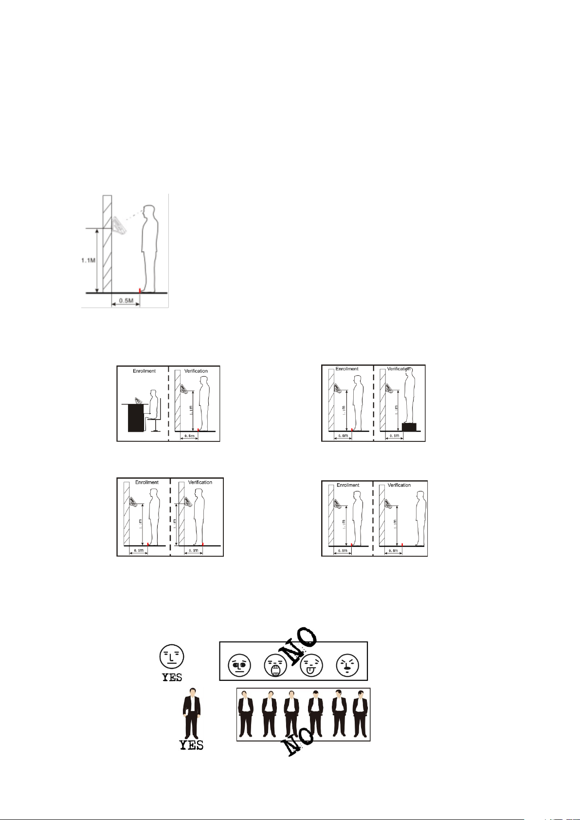
The recommended distance between person and device
n the face image is
1. Instruction for Use
1.1 The distance, Facial Expression and Standing Pose
Recommended distance:
should be 0.5m (applicable to a height range of 1.5~1.85m).
According to the obtained face image from device to adjust,
when the face image is comparatively bright, please move
backwards appropriately; whe
comparatively dark, please move forwards appropriately.
Some improper ways for Enrollment and Verification:
Different posture Different height
Too close Too far
Recommended facial expression and standing position:
VF Series User Manual Page | 1
Page 6
Note: During enrollment and verification, try to have a relaxed face expression and stand upright.
1.2 Enrollment and Verification Pose
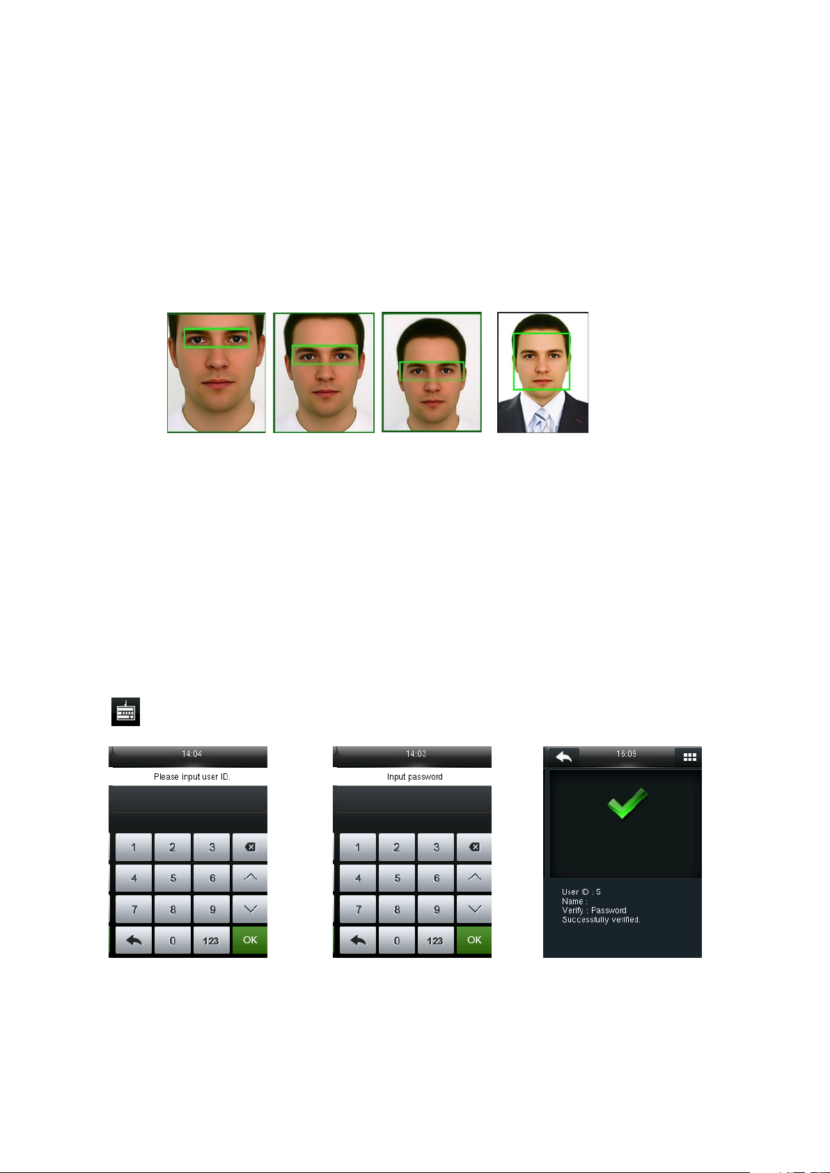
During enrollment, you need to move forward or backward to ensure that your eyes are within the
green frame.
During verification, ensure that the face is displayed at the center of the screen and is within the
green frame.
It is recommended that the face should be at the middle of the screen, and focus eyes inside the
green box according to the to the device’s voice prompts.
1.3 Verification Modes
1.3.1 Password Verification
In this verification method, the entered password is verified with the password of the entered user
ID.
Tap on the initial face to enter 1:1 verification mode.
Input user ID and press [OK]. Input password and press [OK]. Verification succeeds.
If you have registered multiple verification modes, the following interface appears after you enter
your ID and press [OK].
VF Series User Manual Page | 2
Page 7
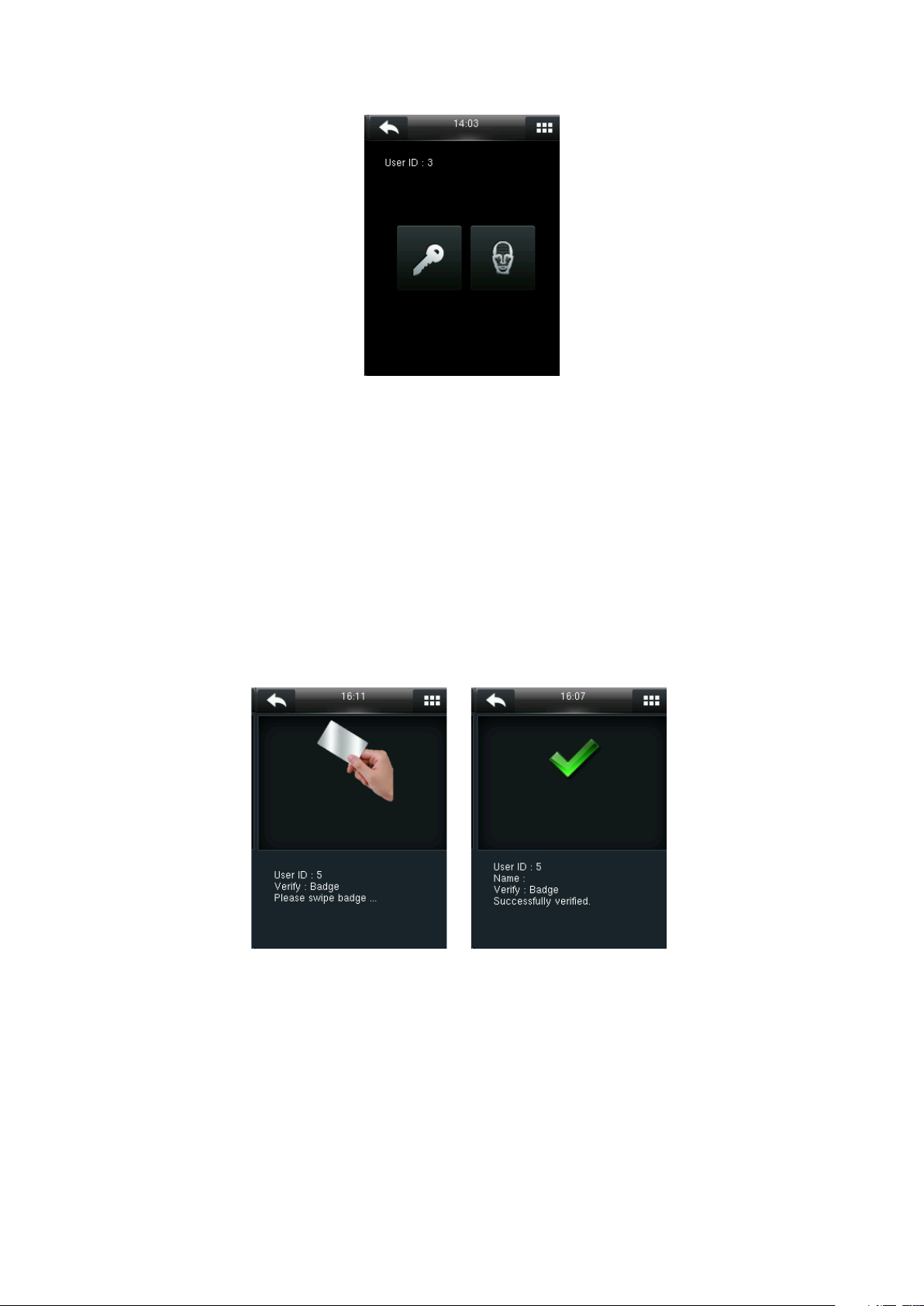
Tap the Key icon to access password verification.
Note: If you have registered only the password, you will access the password verification interface
directly after entering your ID. If you have registered multiple verification modes, the icons of
registered verification modes are displayed, just as the above figure showing that Password and Face
have been registered.
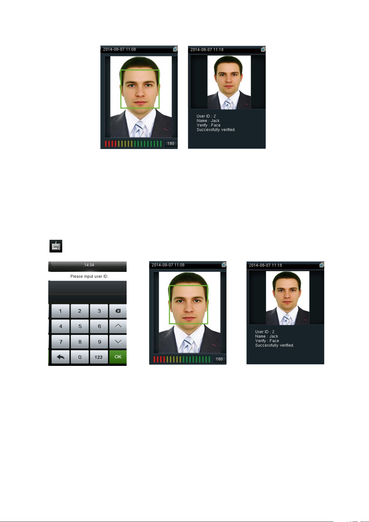
1.3.2 Badge Verification
Swipe your registered badge around the camera area in standby mode. The device prompts “Ou-Ou”
when the badge is unregistered. The device prompts ”Duplicated Punch” when you swipe badge
successfully twice.
1.3.3 1:N face verification
The terminal compares current face image collected by the camera with all face data on the
terminal.
VF Series User Manual Page | 3
Page 8
In initial interface, compares face, Verification succeeds in a proper way.
1.3.4 1:1 face verification
In the 1:1 face verification mode, the device compares current face collected by the camera with
that in relation to the user ID entered through the keyboard. Adopt this mode only when it is
difficult to recognize the face.
Tap on the initial face to enter 1:1 verification mode.
Input user ID and press [OK]. Compare the face in a proper way. Verification Succeeds.
If you have registered multiple verification modes, the following interface appears after you enter
your ID and press [OK].
VF Series User Manual Page | 4
Page 9

Tap the Face icon to access face verification.
Note: If you have registered only your face, you will access the face verification interface directly after
entering your ID. If you have registered multiple verification modes, the icons of registered
verification modes are displayed, as shown in the above figure with Password and Face displayed.
VF Series User Manual Page | 5
Page 10
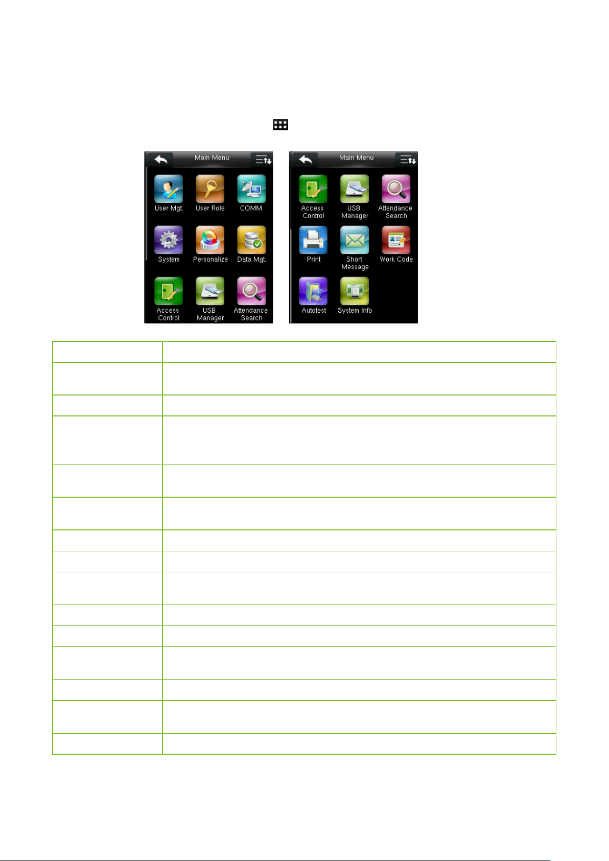
2. Main Menu
When the device is in standby mode, press to open the main menu.
Menu Item Description
User Mgt.
User Role
Comm.
System
Personalize
Data Mgt.
Access Control
USB Manager
Attendance Search
Print★
Basic information of registered users, including user ID, name, user role, verification
mode, face, badge, password and user photo.
To set user roles for accessing into the menu and modifying settings.
To set the related parameters of the communication between the device and PC,
including Ethernet parameters such as IP Address etc., Serial Comm., PC Connection,
Wireless Network and Cloud Sever Setting.
To set related parameters of the system and upgrade firmware, including setting date
& time, attendance, face parameters, resetting to factory settings and USB upgrade.
This includes interface display, voice, bell, punch state key mode and shortcut key
settings.
Manage data in the device, such as delete data, backup data and restore data.
This includes setting the parameters of the lock.
To transfer data such as user data and attendance logs from the USB disk to the
supporting software or other devices.
To search for the records stored in the device after successful verification.
To set printing information and functions (if printer is connected to the device).
Short Message
Work Code
Auto test
System Info
VF Series User Manual Page | 6
To set public or private short messages, which are read by specified person within the
specified time after attendance, facilitating information transmission.
To mark different work categories, facilitating user attendance check.
To automatically test different module’s functions, including the LCD, voice, face and
clock RTC test.
To check device capacity, device and firmware information.
Page 11
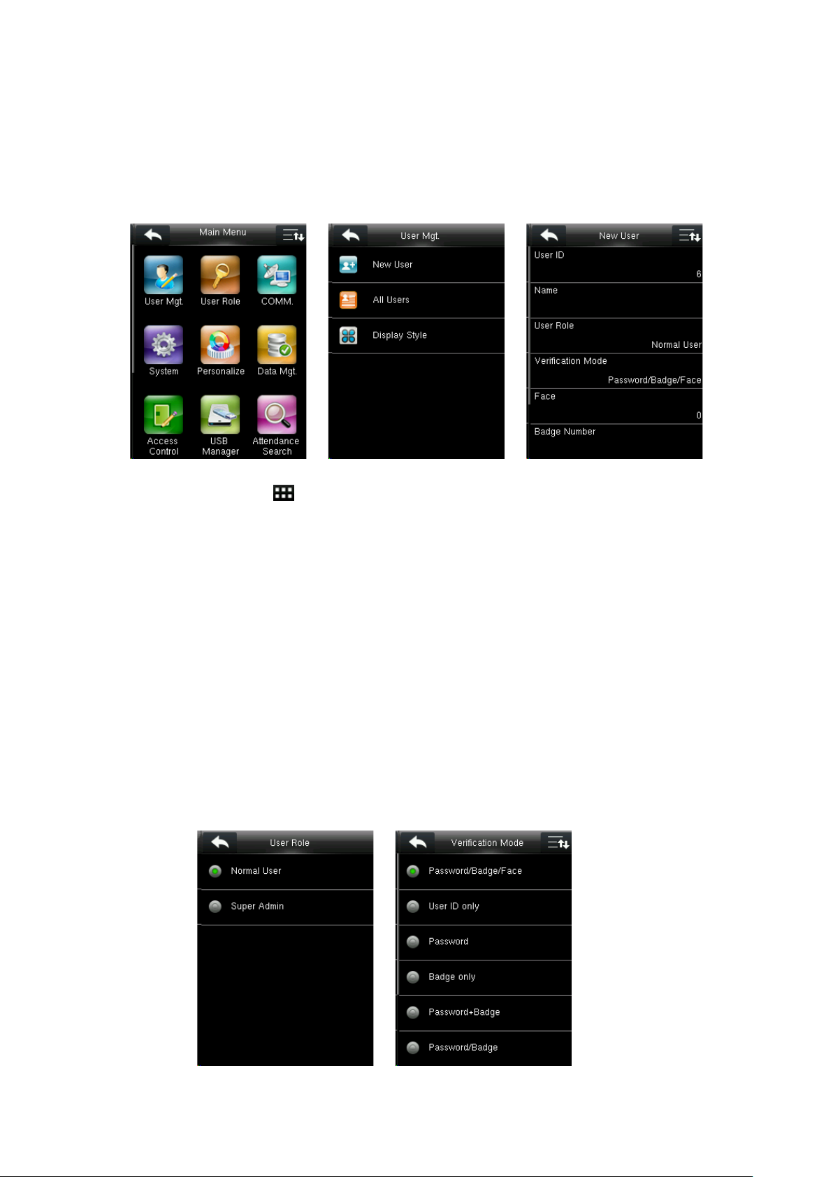
3. User Management
3.1 Adding User
In the initial interface, press > User Mgt. > New User to enter New User setting interface. It
includes inputting User ID and Name, choosing User Role and Verification Mode, registering Face,
Badge Number and User Photo, setting Password.
3.1.1 Enter User ID and Name
Device automatically allocates an ID starting from 1 for every user in sequence. You can also
manually input an ID.
Notes:
1) The device supports user ID ranging from 1 to 9 digits.
2) “Name” field supports maximum of 24 characters.
3.1.2 Select User Role and Verification Mode
VF Series User Manual Page | 7
Page 12
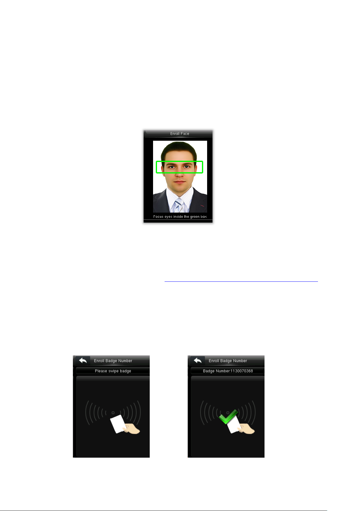
Add a Super Admin: Choose “Super Admin” in [User Role]. A Super Admin can operate all the
functions of the menu.
Add a Normal User: Choose “Normal User” in [User Role]. When the Super Admin is set, Normal
Users can only use password, badge or face for verification; when the Super Admin is not yet set,
Normal Users can operate all functions of the menu.
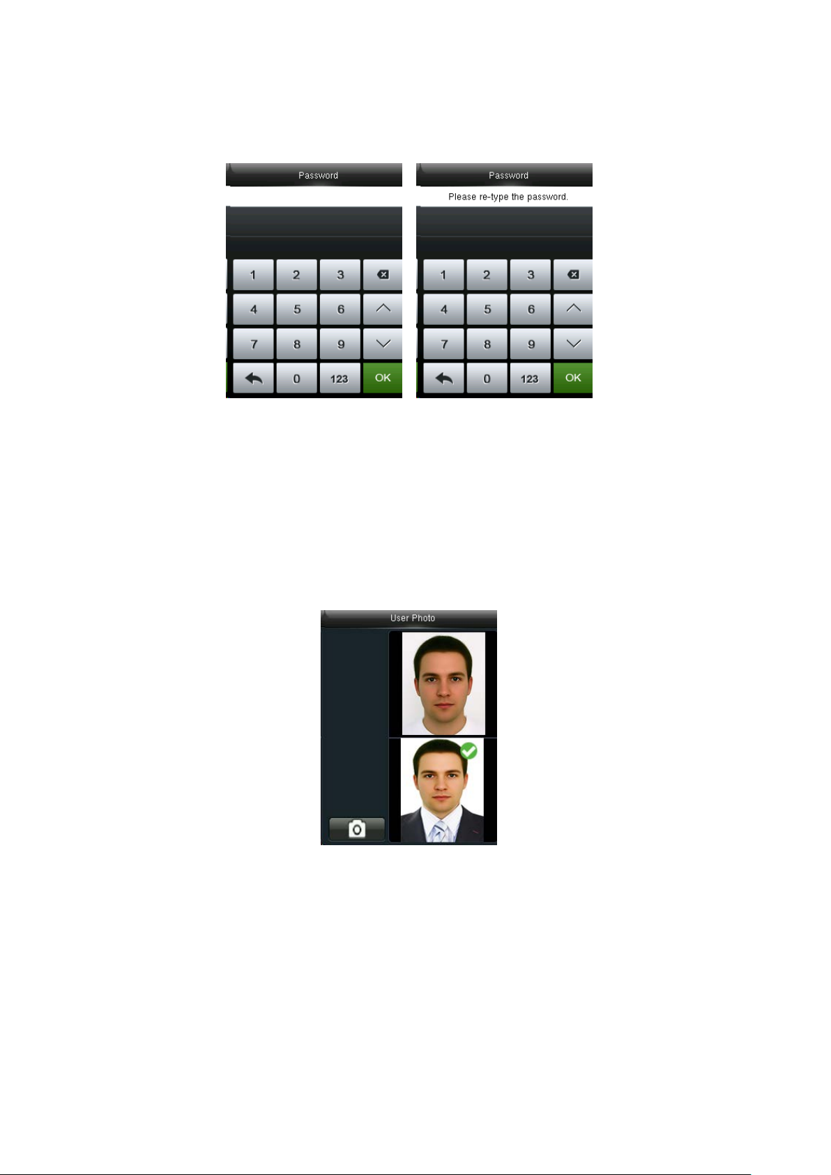
3.1.3 Enroll a Face
Press [Face] on the New User interface. Focus eyes inside the green box as the device prompts,
until enrollment succeeds.
Notes:
1) For the methods of face enrollment, see 1.1 The distance, Facial Expression and Standing Pose.
2) During face enrollment, the system will take a photo and saves it into the device automatically
when the green box moves to middle of the screen.
3.1.4 Enroll a Badge Number
Press [Badge Number] on the New User interface.
Swipe the badge near the camera. The badge number registration succeeds.
VF Series User Manual Page | 8
Page 13
3.1.5 Enroll a Password
Press [Password] on the New User interface. Input password with numeric keyboard and press
[OK]. Re-type the password and press [OK].
Password: It may contain 1 to 8 digits.
3.1.6 Enroll Photo
If you had enrolled photo, the system will display enrolled photo in addition to ID and name after
you pass the verification.
Press [User Photo] on the New User interface. Stand before the screen in your natural posture and
press the camera icon to take a photo.
Note: You need not take photo again if photo captured during face enrollment is already applied.
3.2 Searching for a User
VF Series User Manual Page | 9
Page 14
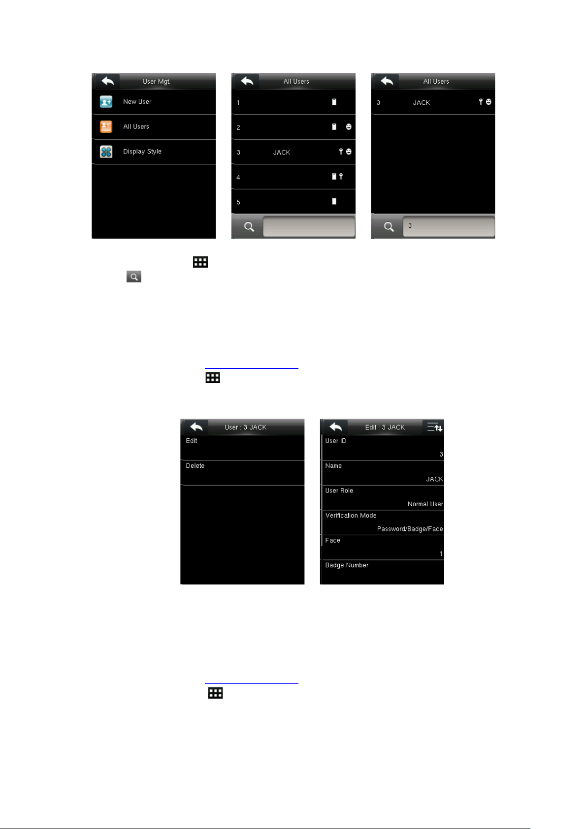
In the initial interface, press > User Mgt. > All Users to enter All Users interface. Input User
ID or Name in , the corresponding user will be shown. As shown in the above figure, search for
the user with the user ID of “3”.
3.3 Editing User
After a user is selected through Searching for a User, press [Edit] to enter user editing interface.
Or in the initial interface press > User Mgt. > All Users > Select a user > Edit to enter user
editing interface.
The method of editing user is the same with that of adding user, only the user ID cannot be edited.
3.4 Deleting User
After a user is selected through Searching for a User, press [Delete] to enter user deleting interface.
Or in the initial interface press > User Mgt. > All Users > Select a user > Delete to enter
user deleting interface.
VF Series User Manual Page | 10
Page 15

Note: If the user has registered face, password, badge number and user photo, the system will
show delete option for these separately.
3.5 User Display Style
In the initial interface, press > User Mgt. > Display Style to enter Display Style setting
interface.
Several display styles are shown as below:
Single Line Multiple Line Mixed Line
VF Series User Manual Page | 11
Page 16

4. User Role
Setting user rights to give authorization for operating the menu (a maximum of 3 roles can be set).
When user role is enabled, in [User Mgt.] > [New User] > [User Role], you can allocate suitable
user role to each user.
Role: Super user needs to allocate different rights to new users. To avoid setting rights for each
user one by one, you can set user roles to categorize different permission levels in user
management.
4.1 Enabling User Role
In the initial interface, press > User Role > User Defined Role 1 (2 / 3) > Enable Defined
Role to enable defined role.
After enabling defined roles, you can check the enabled user roles in [User Mgt.] > [New User] >
[User Role].
Note: At least one registered Administrator is required to enable user role.
4.2 Rights Allocation
VF Series User Manual Page | 12
Page 17

In the initial interface, press > User Role > User Defined Role 1 (2 / 3) > Define User Role to
enter rights allocating interface. Select or cancel the operating right to each menu for User Defined
Role 1 (2 /3).
VF Series User Manual Page | 13
Page 18

actual network situation.
Dynamic Host Configuration Protocol, which is to dynamically allocate IP
5. Communication Settings
In the initial interface, press > COMM. to enter communication setting interface. It Includes
ethernet parameters such as IP address etc., Serial Comm., PC connection, Wireless Network and
Cloud Server Setting.
5.1 Ethernet Settings
When the device communicates with a PC over the Ethernet, you need to set network settings.
Press Ethernet on the Comm. Settings interface.
Menu Item Description
The default value is 192.168.1.201, please adjust them according to the
IP Address
The default value is 255.255.255.0, please adjust them according to the
Subnet Mask
The default value is 0.0.0.0, please adjust them according to the actual
Gateway
The default value is 0.0.0.0, please adjust them according to the actual
DNS
The default value is 4370, please adjust them according to the actual
TCP COMM. Port
actual network situation.
network situation.
network situation.
network situation.
DHCP
Display in Status
Bar
addresses for clients via server. If DHCP is enabled, IP cannot be set
manually.
To set whether to display the network icon on the status bar.
5.2 Serial Comm. Settings
VF Series User Manual Page | 14
Page 19

To establish communication with the device through a serial port, you need to set serial port
settings.
Press Serial Comm. on the Comm. Settings interface.
Baudrate: The rate of the communication with PC; there are 4 options of baudrate: 115200
(default), 57600, 38400 and 19200. The higher the baudrate, the faster is the communication speed,
but also the less reliable. In general, a higher baudrate can be used when the communication
distance is short; when the communication distance is long, choosing a lower baudrate would be
more reliable.
5.3 PC Connection
To improve security of data, Comm Key for communication between the device and PC needs to
be set.
If a Comm Key is set in the device, the correct connection password needs to be entered when
the device is connected to the PC software, so that the device and software can communicate.
Press PC Connection on the Comm. Settings interface.
Menu Item Description
Comm Key: The default password is 0 (no password).
Comm Key
Device ID
Comm Key can be 1~6 digits and in a range of
0~999999.
Identity number of the device, which ranges between
1~254. If the communication method is RS232,
inputting this device ID in the software communication
interface is required.
5.4 Wireless Network
VF Series User Manual Page | 15
Page 20

WIFI is the short of Wireless Fidelity. Our device has a built-in WIFI module to achieve the wireless
network function. Data transmit through WIFI, provides a wireless network environment for the
device.
WIFI Connection
Press Wireless Network on the Comm. Settings interface. Enable WIFI, the device will search
available WIFI in the network range.
Select an available WIFI. Input password and press [OK]. When the WIFI is connected successfully,
the initial interface will display the logo. Select the connected WIFI signal to view the IP
address and other information.
Adding WIFI Network Manually
If you want to connect a WIFI network other from the available list, then you can add it manually.
Press Add WIFI Network on the Wireless Network interface to enter the relevant parameters
(The added network must exist).
Note: To find the added user name in the WIFI list for the connecting method, after manually
adding the WIFI network, please refer to WIFI Connection.
Advanced Setting
Press Advanced on the Wireless Network interface. Set the relevant parameters as required.
VF Series User Manual Page | 16
Page 21

DHCP: Dynamic Host Configuration Protocol, which is to dynamically allocate IP addresses for
clients via server. If DHCP is enabled, IP cannot be set manually.
IP Address: IP address for WIFI network, the default is 0.0.0.0, you can modify it as per the actual
network environment.
Subnet Mask: The default is 255.255.255.0, you can modify it as per the actual network
environment.
Gateway: The default is 0.0.0.0, you can modify it as per the actual network environment.
5.5 Cloud Server Setting
This setting is used for connecting with ADMS server. Press Cloud Server Setting on the Comm.
Settings interface.
When the Webserver is connected successfully, the main interface will display the logo.
Menu Item Description
When this function is enabled, the domain
name mode http://... will be used, such as
Enable Domain
Name
Server Address
Server Port
Enable Proxy
Server
http://www.XYZ.com
domain name when this mode is on; when
this mode is off, enter the IP address format in
IP address of the ADMS server.
Port used by the ADMS server.
Method of enabling proxy. To enable proxy,
please set the IP address and port number of
the proxy server.
. XYZ denotes the
XYZ.
VF Series User Manual Page | 17
Page 22

6. System Settings
It is used to set related system parameters to maximize the performance of the device.
In the initial interface, press > System to enter system setting interface.
6.1 Date/Time Settings
Press Date Time on the System interface. It includes setting date, time, 24-hour time, date format
and daylight saving time. When resetting to factory settings, the date format can be restored
(YYYY-MM-DD).
Note: When resetting to factory settings, the device’s date/time will not be restored (if the
date/time is set to 18:30 on January 1, 2020, after settings are reset, the date/time will stay at 18:30
on January 1, 2020.
6.1.1 Daylight Saving Time
The Daylight Saving Time is a widely used system of adjusting the official local time forward to save
energy. The uniform time adopted during the implementation of this system is known as the DST.
Typically, clocks are adjusted one hour forward in the summer to make people early to bed and
early to rise so as to make full use of illumination resources and save electricity. Clocks are adjusted
backward in autumn. The specific DST regulations vary with countries.
To meet the DST requirement, the device supports the DST function to adjust forward one hour at
×× (Hour): ×× (Minute) ×× (Day) ×× (Month) and backward one hour at ×× (Hour): ×× (Minute) ××
(Day) ×× (Month).
VF Series User Manual Page | 18
Page 23
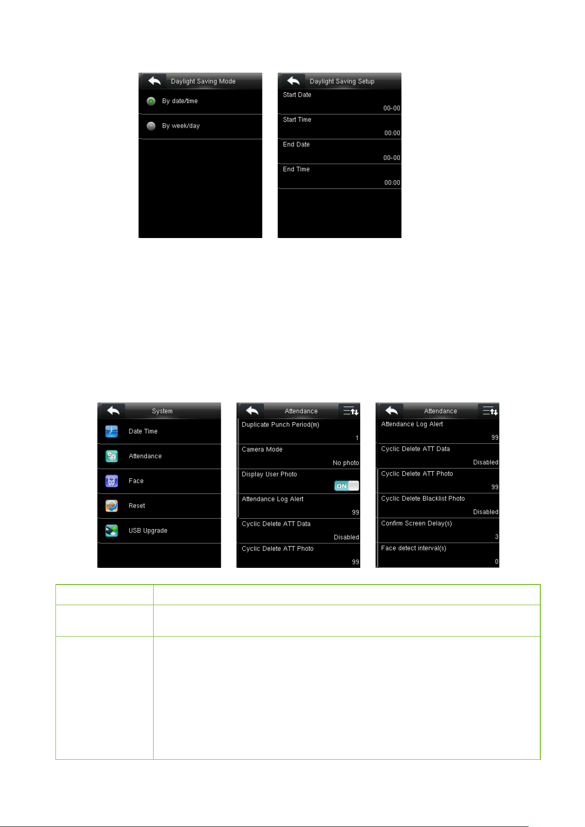
Press Daylight Saving Time to enable it. Select a daylight saving mode and set when to start and
end the daylight saving time.
Note: The end time of DST cannot be set to next year. More specifically, the end time must be later
than the start time in the same year.
6.2 Attendance Parameters
Press Attendance on the System interface.
Menu Item Description
Duplicate Punch
Period (m)
Within a set time period (unit: minutes), the duplicated attendance logs will not be
reserved (value ranges from 1 to 999999 minutes).
To set whether to take and save photos in verification; applicable to all users. The
following 5 modes are included:
No Photo: No photo is taken in user verification.
Camera Mode
Save on successful verification: Photo is taken and saved in successful verification.
VF Series User Manual Page | 19
Take photo, no save: Photo is taken but not saved in verification.
Take photo and save: Photo is taken and saved in verification.
Page 24

Low
High
80
70
Menu Item Description
Save on failed verification: Photo is taken and saved in failed verification.
Display User
Photo
Attendance Log
Alert
Cyclic Delete ATT
Data
Cyclic Delete ATT
Photo
Cyclic Delete
Blacklist Photo
Confirm Screen
Delay(s)
Face Detect
Interval (s)
To set user photo to be displayed when a user passes verification. Turn it [ON] to display
When the remaining storage is less than the set value, the device will automatically
alert users to the remaining storage information. It can be disabled or set to a value
The number of attendance logs allowed to be deleted at one go when the maximum
storage is attained. It can be disabled or set to a value ranging from 1 to 999.
The number of attendance photos allowed to be deleted at one go when the
maximum storage is attained. It can be disabled or set to a value ranging from 1 to 99.
The number of blacklist photos allowed to be deleted at one go when the maximum
storage is attained. It can be disabled or set to a value ranging from 1 to 99.
The display of the verification information interface after verification. Value ranges from
To set the face comparison interval as required, within the range of 0-9 s.
6.3 Face Parameters
user photo and [OFF] to disable it.
ranging from 1 to 9999.
1 to 9 seconds.
Press Face on the System interface.
The recommended thresholds are as follows:
FRR FAR
High Low 85 80
Menu Item Description
Under 1:1 Verification Method, only when the similarity between the verifying face and the
1:1 Match
Threshold
1:N Match
Threshold
user’s registered faces is greater than this value can the verification succeed. The valid value
range is 70-120, with larger threshold leading to lower misjudgment rate and higher
Under 1:N Verification Method, only when the similarity between the verifying face and all
registered faces is greater than this value can the verification succeed. The valid value range
is 80-120, with larger threshold leading to lower misjudgment rate and higher rejection rate,
Medium Medium 82 75
rejection rate, and vice versa.
and vice versa.
Match Threshold
1:N 1:1
VF Series User Manual Page | 20
Page 25

Menu Item Description
This parameter is used to set the exposure value of the camera.
Exposure
Quality
This parameter is used to set a quality threshold for the facial images obtained. The FFR
terminal accepts the facial images and processes them by adopting the facial algorithm
when their quality is higher than the threshold; otherwise, it filters these facial images.
Note: Improper adjustment of the Exposure and Quality parameters may severely affect the
performance of the device. Please adjust the Exposure and Quality parameter only under the
guidance of after-sales service personnel from our company.
6.4 Reset to Factory Settings
Reset data such as communication settings and system settings to factory settings.
Press Reset on the System interface. Click OK to finish the reset setting.
6.5 USB Upgrade
With this option, the device firmware can be upgraded by using the upgrade file in a USB disk.
Before conducting this operation, ensure that the USB disk is properly inserted into the device and
contains the correct upgrade file.
NOTE: If upgrade file is needed, please contact out technical support. Firmware upgradation is not
recommenced under normal circumstances.
VF Series User Manual Page | 21
Page 26
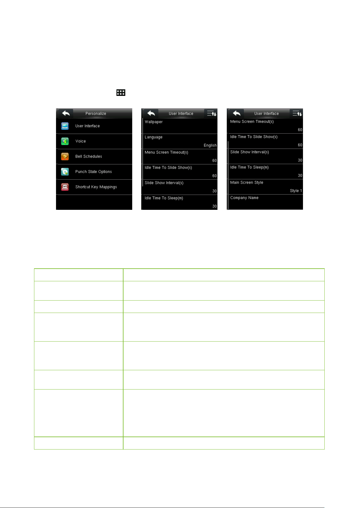
7. Personalize Settings
Conduct related settings of user interface, voice, bell schedules and punch state options, and
customize shortcut keys.
In the initial interface, press > Personalize to enter personalize setting interface.
7.1 User Interface Settings
You can customize the display style of the home interface.
Press User Interface on the Personalize interface.
Menu Item Description
Wallpaper
Language
Menu Screen Timeout (s)
Idle Time To Slide Show (s)
Slide Show Interval (s)
Idle Time To Sleep (m)
Select the wallpaper of main screen as required, you can find wallpapers
When there is no operation in the menu interface and the time exceeds
the set value, the device will automatically exit to the initial interface. You
can disable it or set the value to 60~99999 seconds.
When there is no operation in the initial interface and the time exceeds
the set value, a slide show will be shown. It can be disabled (set to “None”
This refers to the interval between displaying different slide show
When there is no operation in the device and the set Sleep Time is
attained, the device will enter standby mode. Press any key or finger to
cancel standby mode. You can disable this function, or set the value to
1~999 minutes. If this function is turned to [Disabled], the device will not
of various styles in the device.
Select the language of device as required.
or set to 3~999 seconds.
pictures. It can be disabled or set to 3~999 s.
enter standby mode.
Main Screen Style
Choosing the position and ways of the clock and status key.
7.2 Voice Settings
VF Series User Manual Page | 22
Page 27

Press User Interface on the Personalize interface.
Menu Item Description
Voice Prompt
Touch Prompt
Volume
Select whether to enable voice prompts during
operation.
Select whether to enable keyboard voice while
pressing keyboard.
Set the volume of device.
7.3 Bells Settings
Many organization choose to use bell to signify on-duty and off-duty time. When the scheduled
time for bell is reached, the device will play the selected ringtone automatically till the set ringing
duration.
7.3.1 Add a Bell
Press Bell Schedules on the Personalize interface.
Select New Bell Schedule to enter the New Bell Schedule adding interface.
Bell Status: [ON] is to enable the bell, while [OFF] is to disable it.
Bell Time: The bell rings automatically when reaching the specified time.
Repeat: To set whether to repeat the bell.
Ring Tone: Ringtone played for bell.
Interval bell delay (s): To set the ringing duration. The value ranges from 1 to 999 seconds.
7.3.2 Edit a Bell
VF Series User Manual Page | 23
Page 28

On the All Bell Schedules interface, tap the bell item to be edited.
Press Edit. Edit interface is the same as that of new adding, you can modify bell setting as required.
7.3.3 Delete a Bell
On the All Bell Schedules interface, tap a bell item to be deleted.
Press Delete and select Yes to delete this bell.
7.4 Punch States Settings
Press Punch State Options on the Personalize interface.
Menu Item Description
Select a punch state mode, which can be:
Off: To disable the punch state key function. The punch state key set under Shortcut
Key Mappings menu will become invalid.
Manual Mode: To switch the punch state key manually, and the punch state key will
disappear after Punch State Timeout.
Auto Mode: After this mode is chosen, set the switching time of punch state key in
Punch State Mode
Shortcut Key Mappings; When the switching time is reached, the set punch state
key will be switched automatically.
Manual and Auto Mode: Under this mode, the main interface will display the
auto-switching punch state key, meanwhile supports manually switching punch
state key. After timeout, the manually switching punch state key will become
auto-switching punch state key.
Manual Fixed Mode: After punch state key is manually switched, the punch state
key will remain unchanged until being manually switched next time.
VF Series User Manual Page | 24
Page 29
Menu Item Description
Fixed Mode: Only the fixed punch state key will be shown and it cannot be
switched.
Punch State
Timeout (s)
Punch State
Required
The timeout time of the display of punch state. The value ranges from 5~999
seconds.
Whether it is necessary to choose attendance state in verification.
7.5 Shortcut Keys Settings
Shortcut keys can be defined as punch state keys or menu function key. When the device is on the
main interface, pressing the set shortcut key will display the attendance state or enters the menu
operation interface.
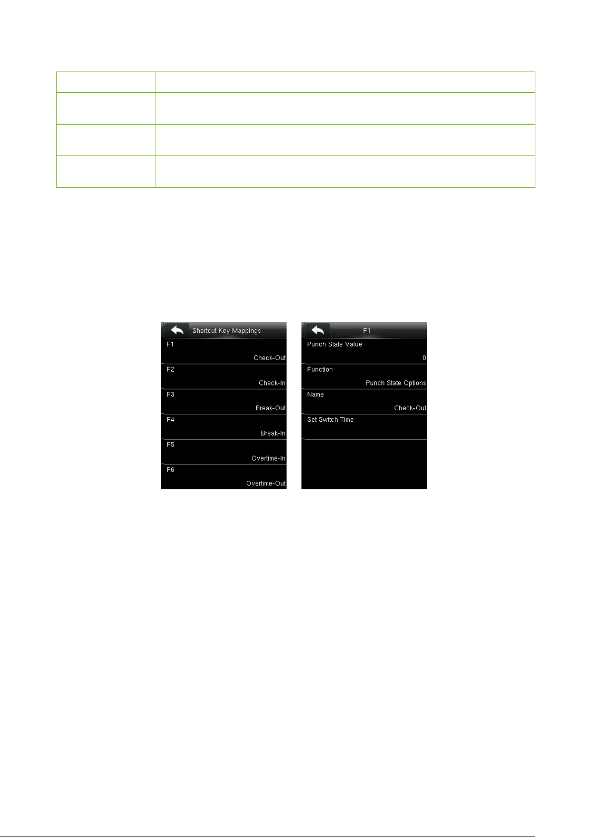
Press Shortcut Key Mappings on the Personalize interface.
Options states are as below:
Only when Function is selected as Punch State Options, Punch State Value, Name, Set Switch
Time, options will appear on the interface.
If Function is selected as other option, there will no Punch State Value, Name, Set Switch Time
options on the interface.
Punch State Value: The valid value ranges from 0 to 250.
Function: Select punch state options or menu function options.
Name: Enter name of punch state.
Set Switch Time: Set switch time for punch state. When Punch State Mode in Punch State
Options interface is set as Auto Mode or Manual and Auto Mode, punch state will be switched
automatically after reaching the set switch time.
Note:
1) When Function of shortcut key is set as Punch State Options, the punch state can be set as
auto switch in Punch State Options interface. Auto switch means that punch state will be
switched automatically after reaching the set switch time.
VF Series User Manual Page | 25
Page 30

2) Select Function of shortcut key as Punch State Options. The shortcut key will not take effect
if Punch State Mode in Punch State Options interface is set as OFF. (For detail setting,
please refer to 7.4 Punch States Settings.)
VF Series User Manual Page | 26
Page 31

8. Data Management
To manage data in the device, which includes deleting data, backup data and restoring data.
In the initial interface, press > Date Mgt. to enter data management interface.
8.1 Delete Data
Press Delete Data on the Data Mgt. interface.
Menu Item Description
Delete Attendance Data
Delete Attendance Photo
To delete all blacklisted photos in the device, which means the photos taken after
Delete Blacklist Photo
Delete All Data
Delete Admin Role
Delete User Photo
Delete Wallpaper
Delete Screen Savers
To delete all attendance data in the device.
To delete all users’ attendance photos in the device.
To delete all user information and attendance logs etc.
To make all Administrators as Normal Users.
failed verifications.
To delete all user photos in the device.
To delete all wallpapers in the device.
To delete all screen savers in the device.
Note: When deleting the attendance record, attendance photo or blacklist photo, you can select
Delete All or Delete by Time Range. When Delete by Time Range is selected, you need to set
the time range for data deletion.
8.2 Data Backup
To backup data to U disk.
Press Backup Data on the Data Mgt. interface.
VF Series User Manual Page | 27
Page 32

8.3 Data Restoration
To restore the data in U disk to the device.
Press Restore Data on the Data Mgt. interface.
VF Series User Manual Page | 28
Page 33

9. Access Control
9.1 Access Control Options Settings
In the initial interface, press > Access Control to enter access control setting interface.
It is used to set the parameters of the equipment control lock and related equipment.
Press Access Control Options on the Access Control interface.
Menu Item Description
Door Lock Delay (s)
Door Sensor Delay (s)
Door Sensor Type
Door Alarm Delay (s)
Speaker Alarm
The time-period of unlocking (from door opening to closing automatically) after the
electronic lock receives an open signal sent from the device (value ranges from 0 to
10 seconds)
When the door is opened, the door sensor will be checked after a time period; if the
state of the door sensor is inconsistent with that of the door sensor mode, alarm will
be triggered. The time period is the Door Sensor Delay (value ranges from 1 to 255
seconds).
It includes Normal Open, Normal Close and None. None means door sensor is not
in use; Normal Open means the door is opened when electricity is on; Normal Close
means the door is closed when electricity is on.
When the state of the door sensor is inconsistent with that of the door sensor type,
alarm will be triggered after a time period; this time period is the Door Alarm Delay
(the value ranges from 0 to 999 seconds).
When the [Speaker Alarm] is enabled, the speaker will raise an alarm when the
device is being dismantled.
VF Series User Manual Page | 29
Page 34

10. USB Manager
You can import the user information and attendance data in the device to matching attendance
software for processing by using a USB disk, or import the user information to other devices for
backup.
Before uploading/downloading data from/to the USB disk, insert the USB disk into the USB slot
first.
In the initial interface, press >USB Manager to enter USB manager interface.
10.1 USB Download
Press Download on the USB Manager interface.
Menu Item Description
Attendance Data
User Data
User Portrait
Attendance Photo
To download all blacklisted photos (photos taken after failed verifications) from the
Blacklist Photo
Work Code
Short Message
To download attendance data in specified time period into USB disk.
To download all user information from the device into USB disk.
To download all user pictures from the device into a USB disk.
To download all attendance photos from the device into USB disk.
device into USB disk.
To save the work code in the device to a USB disk.
To download the short message set in the device to a USB disk.
10.2 USB Upload
Press Upload on the USB Manager interface.
VF Series User Manual Page | 30
Page 35

Menu Item Description
Upload User Data
Upload User
Portrait
Upload Work Code
Upload Short
Message
Upload Screen
Saver
To upload all the user information from USB disk into the device.
To upload the JPG picture named after a work code in the USB disk to the device. During
uploading, you can select Upload Current Picture or Upload All Pictures. The picture is
displayed after successful authentication.
During uploading, you need to create a folder named "picture" in the root directory of the
USB disk, and put the user picture in this directory. A maximum of 2000 pictures are
supported and each picture cannot exceed 20 KB. Pictures are named in the format of
X.jpg, of which X indicates the actual user ID and must be in JPG format.
To upload work codes in the USB disk to the device.
To upload short messages saved in the USB disk to the device.
To upload all screen savers from USB disk into the device. You can choose Upload
selected picture or Upload all pictures. The images will be displayed on the device’s
main interface after upload. During uploading, you need to create a folder named
"advertise" in the root directory of the USB disk, and put the advertising pictures in this
directory. A maximum of 20 pictures are supported and each picture cannot exceed 30 KB.
The picture name and format are not limited, with formats such as jpg, png and bmp
supported.
To upload all wallpapers from USB disk into the device. You can choose Upload selected
picture or Upload all pictures. The images will be displayed on the screen after the
Upload Wallpaper
upload. During uploading, you need to create a folder named "wallpaper" in the root
directory of the USB disk, and put the wallpaper pictures in this directory. A maximum of
20 pictures are supported and each picture cannot exceed 30 KB. The picture name and
format are not limited, with formats such as jpg, png and bmp supported.
10.3 Download Options Settings
Press Download Options on the USB Manager interface.
VF Series User Manual Page | 31
Page 36

Menu Item Description
Encrypt Attendance
Data
Delete ATT D a t a
During uploading and downloading, the
attendance data is encrypted.
After successful downloading, the
attendance data on the device is deleted.
VF Series User Manual Page | 32
Page 37

11. Attendance Search
When users verify successfully, attendance records are saved in the device. This function enables
users to check attendance logs.
In the initial interface, press >Attendance Search to enter attendance search interface.
The process of querying attendance pictures and blacklist pictures is the same as that of querying
attendance records. The following is an example of querying attendance records.
Press Attendance Record on the Attendance Record interface.
1. Enter the user ID to be searched and tap OK. Taping OK without entering a user ID searches
the attendance records of all employees.
2. Select the time range for attendance record query.
3. Tap the record in orange to 4. The above figure shows the
view its details. details of this record.
VF Series User Manual Page | 33
Page 38

12. Print Settings
Devices with printing function can print attendance records out when a printer is connected (this
function is optional and is only equipped in some products).
In the initial interface, press >Print to enter print setting interface.
Press Data Field Setup on the Select the fields needing to be Turn on/off the Paper Cut function.
Print interface. printed.
Note: To turn on the Paper Cut function, it is required to connect the device with a printer with
paper cutting function, so that the printer will cut papers according to the selected printing
information when printing.
VF Series User Manual Page | 34
Page 39
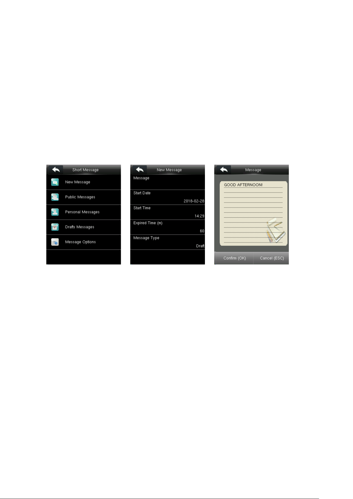
13. Short Message
In this menu option, you can add, edit and delete public or personal message. You can also save
message as draft.
In assigned time, the public message will display to all users at the bottom of main screen, and
personal message will be displayed to specified user after his successful verification.
13.1 Add a New Message
Press New Message on the Short Message interface.
1. Tap Message. Input message content and press OK to save.
2. Set the start date and time: It is the date and time when the short message becomes valid.
3. Set expired time.
Expired Time (m): Valid time for the message, calculated from the Start Time you input. The valid
value of Expired Time ranges from 1 to 65535 minutes. You can also set the message Never Expire,
that is, the message will display always.
4. Select Message type.
Public: SMS able to be seen by all employees.
Personal: SMS aimed at individual only.
Draft: Preset SMS, no difference of individual SMS or common SMS.
When selecting message type as Personal, press Recipient. Select one user or multiple users who
will receive this personal message.
VF Series User Manual Page | 35
Page 40

13.2 Edit and Delete Message
View Message
Press Public Messages on the Short Message interface. Select one message and press View, the
message information will be displayed on the screen.
Edit Message
Press Edit on the interface above. Edit operations are the same as that of adding new.
Delete Message
Press Delete on the interface above. Then select YES to delete.
Note: Personal Messages and Draft Messages options have the same functions as Public
Messages. For detail operation, you can refer to above introduction.
13.3 Message Options
Press Message Options on the Short Message interface.
VF Series User Manual Page | 36
Page 41

Message Show Delay (s): It is the duration for which the personal message is shown. The personal
message showing interface will go back to initial interface after reaching Message Show Delay. The
valid value scope is 1~99999 seconds.
13.4 View the Public Messages and Personal Message
After a public short message is set, the short message icon is displayed on the upper right of
the main interface, and the public short message content is displayed in scroll mode below. The
content of a personal short message is displayed after successful user authentication.
VF Series User Manual Page | 37
Page 42

14. Work Code
Employees’ salaries are subject to their attendance records. Employees may be engaged in
different types of work which may vary with time periods. The salaries varies with work types, the
FFR terminal provides a parameter to indicate the corresponding work type for every attendance
record to facilitate rapid understanding of different attendance situations during the handling of
attendance data.
In the initial interface, press >Work Code to enter work code setting interface.
14.1 Add a Work Code
Press New Work Code on the Work Code interface.
Edit new work code ID and name.
14.2 All Work Codes List
You can view, edit and delete work codes in All Work Codes. The process of editing a work code is
the same as that of adding a work code except that the ID is not allowed to be modified.
View the information about all work codes Edit or delete a work code.
VF Series User Manual Page | 38
Page 43

14.3 Work Code Options
Press Work Code Options on the Work Code interface.
Work Code Required: If selected ON. To verify successfully, you must input
work code after pressing password or face or other verification modes. Select
OFF, you can verify directly without input work code.
Input Screen Timeout (s): After pressing password or other verification
modes, you must input work code in a certain time. If this time is exceeded,
interface of input work code will go back to initial interface. The duration for
input work code is called Input Screen Timeout. Valid value ranges from 1
to 65535 seconds.
Work Code Must Defined: If selected ON, you must input correct wok code
or input nothing to verify successfully. If selected OFF, you can input correct
work code, input nothing or other inexistent work code to verify successfully.
VF Series User Manual Page | 39
Page 44

15. Autotest
Ii automatically test functionality of all modules in the device, which includes the LCD, voice, face
and Clock RTC.
In the initial interface, press >Autotest to enter autotest interface.
Menu Item Description
Test LCD
Test Voice
Test Face
Test Clock RTC
To test the display effect of LCD screen by displaying full color, pure white, and pure black to
check whether the screen displays colors properly.
The device automatically tests whether the voice files stored in the device are complete and
the voice quality is good.
To test if the camera functions properly by checking the pictures taken are clear for use.
To test the Real-Time Clock. The device tests whether the clock works properly and accurately
by checking the stopwatch. Touch the screen to start counting time, and press it again to stop
counting, to see if the stopwatch counts time accurately.
VF Series User Manual Page | 40
Page 45

16. System Information
It checks data capacity, device and firmware information.
In the initial interface, press >System Info. to enter system information interface.
Device Capacity Device Info Firmware Info
Device Capacity: It displays the number of registered users, administrators, passwords, faces,
badges, attendance logs, attendance photos, blacklist photos and user photos, also to check the
total storage of users, faces, badges, attendance records, attendance photos, blacklist photos and
user photos.
Device Info: It displays the device name, serial number, MAC address, face algorithm, platform
information, MCU version, manufacturer and manufacturer date.
Firmware Info: It displays the firmware and system version, Bio service, push service, standalone
service and Dev service.
Note: The display of Device Capacity, Device Info and Firmware Info on the system information
interface of different products may vary; the actual product shall prevail.
VF Series User Manual P a g e | 41
Page 46

5 Appendix 15
 Loading...