


 Loading...
Installation Guide
inBio-Series
Access Control Panels
&
ZKAccess 5.3 software
ZKTecousa.com
2
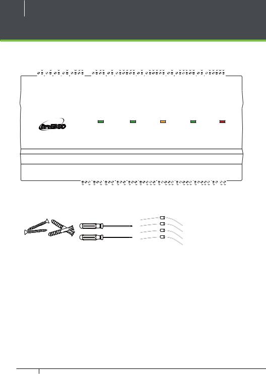
What’s in the Box
|
|
|
|
|
|
|
|
|
|
|
|
|
|
|
|
|
|
|
|
|
|
|
|
|
|
|
IN GND |
IN GND |
IN GND |
|
IN GND |
+12V GND 485485+ |
|
PWR RUN ACT GRD |
IN GND |
BEEP GLED WD1 WD0 |
GND +12V |
IN GND |
BEEP |
GLED WD1 WD0 |
GND +12V |
IN |
GND |
BEEP GLED |
WD1 WD0 GND +12V |
IN GND |
BEEP GLED WD1 WD0 GND +12V |
|
|
|
|
AUX 1 |
AUX 2 |
AUX 3 |
AUX4 |
EXT |
|
STATE |
BUTTON 1 |
READER 1 |
BUTTON |
|
2 |
READER2 |
BUTTON3 |
READER3 |
BUTBUTTON 4 |
READER 4 |
|
|
|
|||
|
|
|
|
|
|
|
|
|
|
|
|
|
|
|
|
|
|
|
|
|
|
|
|
|
|
|
|
|
|
|
|
|
|
|
|
|
|
|
|
|
|
|
|
|
|
|
|
|
|
|
|
|
|
|
|
|
|
|
|
|
|
|
|
|
|
|
|
|
|
|
|
|
|
|
EXT |
PC |
CARD |
RUN |
POWER |
|
RS485 |
RS485 |
||||
|
|
|
Best Security Solution for the World
Advanced Access Control
LAN |
SWITCH |
PC |
AUXOUT1 |
AUXOUT2 |
AUXOUT3 |
AUXOUT4 |
|
LOCK1 |
|
LOCK2 |
|
LOCK3 |
|
LOCK4 |
LOCK |
POWER |
|||||||||||||||
|
485+ |
485SGND |
NO COM NC |
NO COM NC |
NO COM NC |
NO COM NC |
SEN GND NO COM NC |
SEN GND NO COM NC |
SEN GND NO COM NC |
SEN GND NO COM NC |
V+ V- |
+12V GND |
|||||||||||||||||||
|
|
|
|
|
|
|
|
|
|
|
|
|
|
|
|
|
|
|
|
|
|
|
|
|
|
|
|
|
|
|
|
|
|
|
|
|
|
|
|
|
|
|
|
|
|
|
|
|
|
|
|
|
|
|
|
|
|
|
|
|
|
|
|
|
|
|
|
|
|
|
|
|
|
|
|
|
|
|
|
|
|
|
|
|
|
|
|
|
|
|
|
|
|
|
|
2 Screws & Anchors |
2 Screwdriver |
4 Diode |
InBio-Series Access Control Panels & ZKAccess 5.3 software INSTALLATION GUIDE

3
CONTENT
What’s in the Box........................................................................ |
2 |
Optional accessories................................................................ |
4 |
Safety Precautions..................................................................... |
5 |
Product PIN Diagram.............................................................. |
6 |
LED Indicators............................................................................... |
7 |
Product Dimension.................................................................. |
8 |
Installation of Panel & Cabinet......................................... |
9 |
Wiring Legend.......................................................................... |
10 |
Power Wiring Diagram ....................................................... |
11 |
FR1200 Connection.............................................................. |
12 |
DIP Switch Setting for FR1200 Device ID.............. |
13 |
Wiegand Connection.......................................................... |
14 |
REX Connections..................................................................... |
15 |
Lock Connection..................................................................... |
16 |
Connecting a lock with external power supply................. |
16 |
Switching from Dry Contact to Wet Contact...................... |
17 |
Normally Open Lock Powered From Lock Terminal.......... |
18 |
Normally Closed Lock Powered From Lock Terminal....... |
18 |
Aux. I/O connection.............................................................. |
19 |
Aux. Input Connection.............................................................. |
19 |
Aux. Output Connection........................................................... |
19 |
Ethernet Connection .......................................................... |
20 |
LAN Connection.......................................................................... |
20 |
Direct connection....................................................................... |
20 |
RS485 Connection ................................................................ |
21 |
Restore factory setting............................................................... |
22 |
DIP Switch Setting.................................................................. |
23 |
RS485 Address.............................................................................. |
23 |
Terminal Resistance.................................................................... |
23 |
Typical Installation.................................................................. |
24 |
Troubleshooting...................................................................... |
25 |
PC 485 Setting Table............................................................. |
26 |
Electrical Specifications ..................................................... |
28 |
Specifications ............................................................................ |
29 |
ZKAccess 5.3
software
Installation and Setup
starts at page 30
InBio-Series Access Control Panels & ZKAccess 5.3 software INSTALLATION GUIDE

4
Optional accessories
Wiegand Card Reader |
Prox Card |
ZK4500 Enrollment reader |
PTE-1 Exit Button |
FR1200 FP & Prox Reader |
CR10E Card Enroller |
inBio Cabinet
InBio-Series Access Control Panels & ZKAccess 5.3 software INSTALLATION GUIDE

5
Safety Precautions
The following precautions are to keep user’s safe and prevent any damage. Please read carefully before installation
Do not install the device in a place subject to direct sun light, humidity, dust or soot
Do not place a magnet near the product. Magnetic objects such as magnet, CRT, TV, monitor or speaker may damage the device.
Do not place the device next to heating equipment
Be careful not to let liquid like water, drinks or chemicals leak inside the device.
Do not let children touch the device without supervision
Do not drop or damage the device
Do not disassemble, repair or alter the device.
Do not use the device for any other purpose than specified.
Clean the device often to remove dust on it. In cleaning, do not splash water on the device but wipe it out with smooth cloth or towel.
Contact your supplier in case of a problem.
InBio-Series Access Control Panels & ZKAccess 5.3 software INSTALLATION GUIDE

6
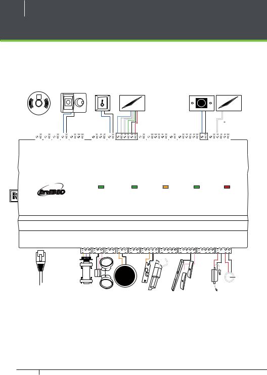
Product PIN Diagram
Inputs Aux 4 |
FR1200 Reader Fingerprint |
Button Exit Door #1 Indictor State |
Reader Card Door #1 |
Reader Card Door #2 |
Button Exit Door #2 |
Reader Card Door #3 |
Button Exit Door #3 |
Reader Card Door #4 |
Button Exit Door #4 |
|
|
|
|
|
|
|
|
|
|
|
|
|
|
|
|
|
|
|
|
|
|
|
|
|
|
|
|
|
IN GND |
IN GND |
IN GND |
|
IN GND |
|
+12V GND 485485+ |
|
PWR RUN ACT GRD |
|
IN GND |
BEEP GLED WD1 WD0 |
GND +12V |
IN GND |
BEEP |
GLED WD1 WD0 |
GND +12V |
IN |
GND |
BEEP GLED |
WD1 WD0 GND +12V |
IN GND |
BEEP GLED WD1 WD0 GND +12V |
|
|
|
|
AUX 1 |
AUX 2 |
AUX 3 |
AUX4 |
|
EXT |
|
STATE |
BUTTON 1 |
READER 1 |
BUTTON |
|
2 |
READER2 |
BUTTON3 |
READER3 |
BUTBUTTON 4 |
READER 4 |
|
|
|
||||
|
|
|
|
|
|
|
|
|
|
|
|
|
|
|
|
|
|
|
|
|
|
|
|
|
|
|
|
|
|
|
|
|
|
|
|
|
|
|
|
|
|
|
|
|
|
|
|
|
|
|
|
|
|
|
|
|
|
|
|
|
|
|
|
|
|
|
|
|
|
|
|
|
|
|
|
|
|
|
|
|
EXT |
PC |
CARD |
RUN |
POWER |
|
RS485 |
RS485 |
||||
|
|
|
Best Security Solution for the World
Advanced Access Control
LAN |
SWITCH |
PC |
AUXOUT1 |
|
AUXOUT2 |
|
AUXOUT3 |
AUXOUT4 |
|
LOCK1 |
|
LOCK2 |
|
|
LOCK3 |
|
LOCK4 |
LOCK |
POWER |
||||||||||||||||||||||
|
|
|
485+ |
485SGND |
NO COM NC |
|
NO COM NC |
|
NO COM NC |
NO COM NC |
SEN GND NO COM NC |
SEN GND NO COM NC |
SEN GND NO COM NC |
SEN GND NO COM NC |
V+ V- |
|
+12V GND |
||||||||||||||||||||||||
|
|
|
|
|
|
|
|
|
|
|
|
|
|
|
|
|
|
|
|
|
|
|
|
|
|
|
|
|
|
|
|
|
|
|
|
|
|
|
|
|
|
|
|
|
|
|
|
|
|
|
|
|
|
|
|
|
|
|
|
|
|
|
|
|
|
|
|
|
|
|
|
|
|
|
|
|
|
|
|
|
|
|
|
|
|
|
|
|
|
|
|
|
|
|
|
|
|
|
|
|
|
|
|
|
|
|
|
|
|
|
|
|
|
|
|
|
|
|
|
|
|
|
|
|
|
|
|
|
|
|
|
|
|
|
|
|
|
|
|
|
|
|
|
|
|
|
|
|
|
|
|
|
|
|
|
|
|
|
|
|
|
|
|
|
|
|
|
|
|
|
|
|
|
|
|
|
|
|
|
|
|
|
|
|
|
|
|
|
|
|
|
|
|
|
|
|
|
|
|
|
|
|
|
|
|
|
|
|
|
|
|
|
|
|
|
|
|
|
|
|
|
|
|
|
|
|
|
|
|
|
|
|
|
|
|
|
|
|
|
|
|
|
|
|
|
|
|
|
|
|
|
Slot Card SD |
Switches DIP LED ACT Port Ethernet LED LINK |
Communication RS485 |
Output Aux 4 |
Sensor Door & Lock 4 |
Power inBio Power Lock |
Figure 1
InBio-Series Access Control Panels & ZKAccess 5.3 software INSTALLATION GUIDE

7
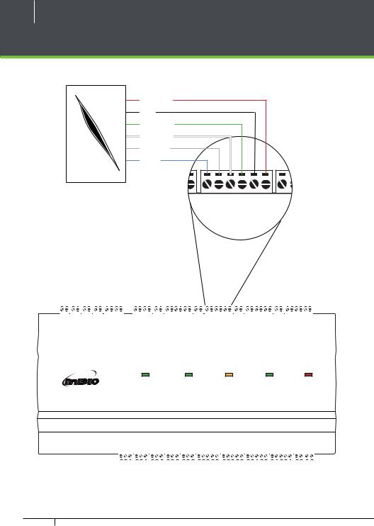
LED Indicators
1 2 3 4 |
LINK Solid Green LED indicates TCP/IP |
communication is normal |
|
O |
|
Figure 2 |
|
1 2 3 4 |
Flashing (ACT )Yellow LED indicates |
data communication is in progress |
O 
N 1 2 3
Figure 3
EXT |
PC |
RS485 |
RS485 |
Figure 4
EXT |
PC |
RS485 |
RS485 |


 EXT RS485 (TX/RX) Flashing Yellow & Green LED indicates communication is in progress

 PC RS485 (TX/RX) Flashing Yellow & Green LED indicates communication is
in progress
Figure 5
RUN |
POWER |
Figure 6
RUN |
POWER |
Figure 7
CARD |
RUN |

 Flashing (POWER) Red LED indicates the panel is powered on.

 Flashing (RUN) Green LED indicates that panel is in normal working state.

 Flashing (CARD) Yellow LED indicates that the card is read by the panel.
Figure 8
InBio-Series Access Control Panels & ZKAccess 5.3 software INSTALLATION GUIDE

8
Product Dimension
inBio-160 |
inBio-260 |
inBio-460 |
|
|
|
|
RS485 EX T |
|
|
|
|
|
|
|
|
|
|
|
|
|
|
|
|
|
|
|
RS485 PC |
Advanced |
|
|
|
|
|
|
|
|
|
|
|
|
||
|
|
|
|
D CA R |
|
|
|
|
|
|
|
|
|
|
|
|
|
|
|
|
|
|
|
RUN |
Access |
|
|
|
|
|
|
|
|
|
|||||
|
|
|
|
|
|
|
|
|
|
|
|
|
|
ER PO W |
Control |
|
|
|
|
|
|
|
|
|
|
|
|
||
|
|
|
|
|
|
|
|
||
|
|
|
|
|
|
|
|
|
|
|
|
|
|
EX T RS485 |
|
|
|
|
8.89in |
|
|
|
|
(226mm) |
7.125in |
|
EX T RS485 |
|
PC RS485 |
|
|
|
|
|
(181mm) |
|
PC RS485 |
|
R |
Advanced |
|
Advanced |
DCA |
|
|
D CA R |
|||
|
Access |
RUN |
Access |
RUN |
|
Control |
ER PO W |
ntrolCo |
ER PO W |
4.17in (106mm) |
4.17in (106mm) |
4.17in (106mm) |
1.42in (36mm) |
Figure 9
inBioMetal Cabinet
|
13in |
|
(330mm) |
15.7in (400mm) |
3.56in |
|
|
|
(90.5mm) |
Figure 10 |
|
InBio-Series Access Control Panels & ZKAccess 5.3 software INSTALLATION GUIDE

9
Installation of Panel & Cabinet
Cable Conduit |
(Punch Hole for cables) |
Advanced Access Control
-- +


 Temper Switch
inBio Panel
Heat Dissipation Grill |
Power Supply
Backup Battery
Figure 11
Step 1 |
Step 2 |
Step 3 |
Pass the cable through holes |
Mount the Metal Cabinet |
Insert the inBio Panel as it shown |
State Indicators |
Mounting Holes |
Inserting Panel to Rail |
1
2
Mounting Rail
Figure 12
We recommend drilling the mounting plate screws into solid wood (i.e. stud/beam). If a stud/beam cannot be found, then use the supplied drywall plastic mollies (anchors).
InBio-Series Access Control Panels & ZKAccess 5.3 software INSTALLATION GUIDE
10
Wiring Legend
Detector |
Sensor IR |
Button Exit |
Reader Card |
Button Exit |
Reader Card |
FIRE ALARM |
PUSH |
PUSHT |
|
OT |
|
T
O
T
HSUP
No Touch |
EXIT |
|
|
|
|
|
|
|
|
|
|
|
|
|
|
|
|
|
|
|
|
|
|
|
|
|
|
|
|
|
|
|
|
|
|
|
|
|
|
|
|
|
|
|
|
|
|
|
|
|
|
|
|
|
|
|
|
|
|
|
|
|
|
|
|
|
|
|
|
|
|
|
|
|
|
|
|
|
|
|
|
|
|
|
|
|
|
|
|
|
|
|
|
|
|
|
|
|
|
|
|
|
|
|
|
|
|
|
|
|
|
|
|
|
|
|
|
|
|
|
|
|
|
|
|
|
|
|
|
|
|
|
|
|
|
|
|
|
|
|
|
|
|
|
|
|
|
|
|
|
|
|
|
|
|
|
|
|
|
|
|
|
|
|
|
|
|
|
|
|
|
|
|
|
|
|
|
|
|
|
|
|
|
|
|
|
|
|
|
|
|
|
|
|
|
|
|
|
|
|
|
|
|
|
|
|
|
|
|
|
|
|
|
|
|
|
|
|
|
|
|
|
|
|
|
|
|
|
|
|
|
|
|
|
|
|
|
|
|
|
|
|
|
|
|
|
|
|
|
|
|
|
|
|
|
|
|
|
|
|
|
|
|
|
|
|
|
|
|
|
|
|
|
|
|
|
|
|
IN GND |
IN GND |
IN GND |
|
IN GND |
|
+12V GND 485485+ |
|
PWR RUN ACT GRD |
IN GND |
BEEP GLED WD1 WD0 |
GND +12V |
IN GND |
BEEP |
GLED WD1 WD0 |
GND +12V |
IN |
GND |
BEEP GLED |
WD1 WD0 GND +12V |
IN GND |
BEEP GLED WD1 WD0 GND +12V |
|
||||||||||||||||||||||||||||||
|
|
AUX 1 |
AUX 2 |
AUX 3 |
AUX4 |
|
|
|
EXT |
|
|
STATE |
BUTTON 1 |
|
READER 1 |
BUTTON |
|
|
2 |
|
READER2 |
BUTTON3 |
READER3 |
BUTBUTTON 4 |
READER 4 |
|
|
|
|
|
|
|
|
|
||||||||||||||||||||
|
|
|
|
|
|
|
|
|
|
|
|
|
|
|
|
|
|
|
|
|
|
|
|
|
|
|
|
|
|
|
|
|
|
|
|
|
|
|
|
|
|
|
|
|
|
|
|
|
|
|
|
|
|
|
|
|
|
|
|
|
|
|
|
|
|
|
|
|
|
|
|
|
|
|
|
|
|
|
|
|
|
|
|
|
|
|
|
|
|
|
|
|
|
|
|
|
|
|
|
|
|
|
|
|
|
|
|
|
|
|
|
|
|
|
|
|
|
|
|
|
|
|
|
|
|
|
|
|
|
|
|
|
|
|
|
|
|
|
|
|
|
|
|
|
|
|
|
|
|
|
|
|
|
|
|
|
|
|
|
|
|
|
|
|
EXT |
PC |
CARD |
RUN |
POWER |
|
RS485 |
RS485 |
||||
|
|
|
Best Security Solution for the World
Advanced Access Control
LAN |
SWITCH |
PC |
AUXOUT1 |
AUXOUT2 |
AUXOUT3 |
AUXOUT4 |
|
LOCK1 |
|
LOCK2 |
|
LOCK3 |
|
LOCK4 |
LOCK |
POWER |
||||||||||||||
|
485+ |
485SGND |
NO COM NC |
NO COM NC |
NO COM NC |
NO COM NC |
SEN GND NO COM NC |
SEN GND NO COM NC |
SEN GND NO COM NC |
SEN GND NO COM NC |
V+ V- |
+12V GND |
||||||||||||||||||
|
|
|
|
|
|
|
|
|
|
|
|
|
|
|
|
|
|
|
|
|
|
|
|
|
|
|
|
|
|
|
RS485 |
ALARM |
Cable Ethernet |
Convertor 485 |
Floodlight |
Lock Open Normally |
Lock Close Normally |
Supply Power DC 12V |
Power DC 12V |
|
|
|
Figure 13 |
|
|
|
InBio-Series Access Control Panels & ZKAccess 5.3 software INSTALLATION GUIDE
11
Power Wiring Diagram
Without Backup Battery
Advanced Access Control
LOCK POWER
V+ V- |
+12V GND |
Ground
Switching Power Supply
Figure 14
With Backup Battery
LOCK POWER
V+ V- |
+12V GND |
Advanced Access Control
-- +
Ground
Switching Power Supply
Figure 15
InBio-Series Access Control Panels & ZKAccess 5.3 software INSTALLATION GUIDE

12
FR1200 Connection
ETHERNET |
|
LAN |
|
|
UXA221AAAUXA |
IN |
EXT |
|
|
|
|
|
IN |
|
|
|
|
|
|
GND |
|
|
|
|
|
UXA33 |
GND |
|
|
|
|
|
IN |
|
|
|
SWITCH |
|
|
AUX4 |
GND |
|
|
|
|
GND |
|
||
|
|
|
|
|
IN |
|
|
|
|
|
|
+12V |
|
|
|
|
|
EXT |
GND |
|
|
|
|
|
|
485- |
|
485+ |
|
|
|
|
485+ |
|
485- |
PC |
|
|
|
|
|
SGND |
|
|
|
|
|
|
NO |
UT1AUXO |
|
|
STATE |
PWR |
|
NC |
|
|
ACT |
|
||
COM |
|
|
|
|
RUN |
|
NC |
UT2AUXO |
|
EXT 5RS48 |
ONBUT11 T |
GRD |
|
|
GND |
|
||||
NO |
|
|
|
|
|
|
COM |
|
|
|
|
IN |
|
COM |
3AUXO |
|
|
READER |
GLED |
|
NO |
|
|
|
|
BEEP |
|
NC |
UT |
|
|
|
WD1 |
|
|
4AUXO |
|
|
BU T |
WD0 |
|
NO |
|
|
GND |
|
||
COM |
UT |
|
PC RS48 |
ETON |
+12V |
|
NC |
|
|
|
|
|
|
SEN |
1 |
|
5 |
|
GND |
|
GND |
LOCK |
|
|
READ2 |
|
|
NO |
|
|
BEEP |
|
||
COM |
|
|
|
|
GLED |
|
NC |
|
|
|
R |
WD1 |
|
|
|
|
|
T2 |
WD0 |
|
SEN |
4LOCK3 LOCK 2 |
Advanced |
CAR D |
R4RON4BUTTBUT3R EADT E 3RON BUT |
GND |
|
SEN |
|
|
||||
GND |
|
|
|
|
+12V |
|
NO |
|
|
|
|
|
|
COM |
|
|
|
|
IN |
|
NC |
|
|
|
|
GND |
|
SEN |
|
|
|
|
BEEP |
|
GND |
|
|
|
|
GLED |
|
NO |
|
|
|
|
WD1 |
|
COM |
|
|
|
|
WD0 |
|
NC |
|
|
|
|
GND |
|
|
|
|
|
|
+12V |
|
GND |
KLOC LOCK |
Access |
RUN |
EADE |
IN |
|
V- |
WD0 |
|
||||
NO |
|
|
|
|
GND |
|
COM |
|
|
|
|
BEEP |
|
NC |
|
|
|
|
GLED |
|
V+ |
POWER |
Control |
POWER |
|
WD1 |
|
+12V |
|
GND |
|
|||
GND |
|
|
|
|
+12V |
|
GND
+12V GND 485485+
|
|
|
|
|
12V DC |
|
12V DC |
1 |
FR1200 |
2 |
FR1200 |
3 |
FR1200 |
8 |
FR1200 |
|
|
|
|
Figure 16 |
|
|
|
InBio-Series Access Control Panels & ZKAccess 5.3 software INSTALLATION GUIDE

13
DIP Switch Setting for FR1200 Device ID
RS485 Terminal Resistance
8
4
2
1
DIP Switch
Figure 17
Address |
|
Switch Settings |
|
Address |
Switch Settings |
|
|
|
|
|
|
|
|
1 |
|
|
|
5 |
|
|
2 |
|
|
|
6 |
|
|
3 |
|
|
|
7 |
|
|
4 |
|
|
|
8 |
|
|
|
|
|
|
|
|
|
Important Notes |
|
|
3. If FR1200 is powered from inBio-460 |
|||
1. There are six DIP switches on the |
panel ,the length of wire should be |
|||||
back of FR1200, Switches 1-4 is for |
less than 100 meters or 330 ft. |
|||||
4. The External RS485 interface can |
||||||
RS485 address, switch 5 is reserved, |
||||||
switch 6 is for reducing noise on long |
supply maximum 500mA current, |
|||||
RS485 cable. |
|
|
The FR1200’s startup current is |
|||
2. Set the odd number for IN reader, |
240mA. So inBio-460 only can only |
|||||
and the even number for OUT reader |
power two FR1200s. |
|||||
5. If the cable length is more than |
||||||
(for eg. For two readers for one door- |
||||||
the RS485 address 1 is for IN reader, |
200 meters or 600 ft , the number 6 |
|||||
RS485 address 2 is for OUT reader) |
switch should be ON as below |
|||||
Distance: More than 200 meters
InBio-Series Access Control Panels & ZKAccess 5.3 software INSTALLATION GUIDE
14
Wiegand Connection
DC+(6-14V) |
GND |
Wiegand D0 |
Wiegand D1 |
Green LED |
Beeper |
Wiegand Card Reader
GND |
BEEP GLED WD1 WD0 |
GND +12V |
IN |
GND |
N 1 |
READER 1 |
BUTTON |
|
|
|
|
|
|
|
|
|
|
|
|
|
|
|
|
|
|
|
|
|
|
|
|
|
|
|
|
|
IN GND |
IN GND |
IN GND |
|
IN GND |
+12V GND 485485+ |
|
PWR RUN ACT GRD |
IN GND |
BEEP GLED WD1 WD0 |
GND +12V |
IN GND |
BEEP |
GLED WD1 WD0 |
GND +12V |
IN |
GND |
BEEP GLED |
WD1 WD0 GND +12V |
IN GND |
BEEP GLED WD1 WD0 GND +12V |
|
|
|
|
AUX 1 |
AUX 2 |
AUX 3 |
AUX4 |
EXT |
|
STATE |
BUTTON 1 |
READER 1 |
BUTTON |
|
2 |
READER2 |
BUTTON3 |
READER3 |
BUTBUTTON 4 |
READER 4 |
|
|
|
|||
|
|
|
|
|
|
|
|
|
|
|
|
|
|
|
|
|
|
|
|
|
|
|
|
|
|
|
|
|
|
|
|
|
|
|
|
|
|
|
|
|
|
|
|
|
|
|
|
|
|
|
|
|
|
|
|
|
|
|
|
|
|
|
|
|
|
|
|
|
|
|
|
|
|
|
EXT |
PC |
CARD |
RUN |
POWER |
|
RS485 |
RS485 |
||||
|
|
|
Best Security Solution for the World
Advanced Access Control
LAN |
SWITCH |
PC |
AUXOUT1 |
AUXOUT2 |
AUXOUT3 |
AUXOUT4 |
LOCK1 |
LOCK2 |
LOCK3 |
LOCK4 |
LOCK |
POWER |
|
|
485+ |
485SGND |
NO COM NC |
NO COM NC |
NO COM NC |
NO COM NC |
SEN GND NO COM NC |
SEN GND NO COM NC |
SEN GND NO COM NC |
SEN GND NO COM NC |
V+ V- |
+12V GND |
|
|
|
|
|
|
|
|
|
|
|
|
|
|
|
|
|
|
|
|
|
|
|
|
|
|
|
|
|
Figure 18
InBio-Series Access Control Panels & ZKAccess 5.3 software INSTALLATION GUIDE
Loading...