

Page 1

Installation Guide
TF1700
Standalone Outdoor Fingerprint Reader Controller
&
ZKAccess | Classic software 3.5
ZKAccess.com
Page 2
2
TF1700
Stick this mounting paper to the wall
or door frame. Drill the holes according
to the mounting paper.
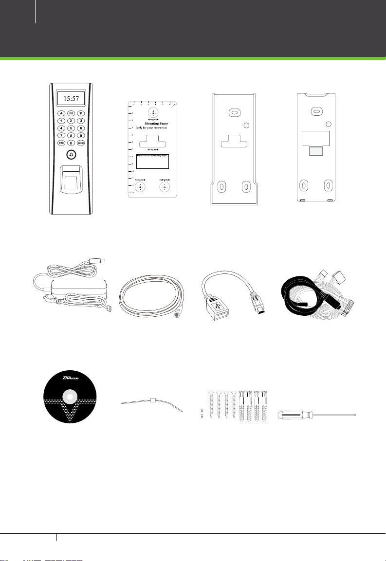
What’s in the Box
TF1700
Installation Template Back PlateRubber Gasket
AC Power Adapter USB Cable AdaptorNetwork Cable Cables
ZKAccess Security Management Software
DiodeZKAccess Software
4 Large Screws & Anchors,
Screwdriver
2 Small screws
TF1700 & ZKAccess CLASSIC 3.5 software INSTALLATION GUIDE
Page 3

CONTENT
What’s in the Box ....................................................................2
Optional accessories ............................................................ 4
Safety Precautions..................................................................5
Product PIN Diagram ...........................................................6
Product Dimension ...............................................................8
Cables and Connectors .....................................................9
Mounting the reader on the wall ............................10
Power Connection .............................................................11
RS485 Connection .............................................................. 12
PC Connection ......................................................................... 12
FR1200 Connection ................................................................ 13
Lock Relay Connection ...................................................14
Normall Open Lock ................................................................. 14
Normall Close Lock ................................................................. 15
Aux. Input Connection .................................................... 16
Exit Button Connection ......................................................... 16
Aux. Output Connection ...............................................17
Alrm Button Connection ....................................................... 17
Door Bell Button Connection............................................... 18
Weigand Input Connection ........................................19
RFID Button Connection ....................................................... 19
Weigand Output Connection ....................................20
Access Control Panel ..............................................................20
Standalone Installation ................................................... 21
FR1200 Connection ................................................................ 21
Installation with Third Party Panels .........................22
C3 Conroller Panel Connection ........................................... 22
inBIO Conroller Panel Connection ...................................... 23
How Does TF1700 work .................................................24
Troubleshooting ..................................................................25
How to Place a Finger on Scanner .........................26
Electrical Specifications ................................................. 28
Specifications ........................................................................29
3
ZKAccess | CLASSIC 3.5
Software Installation and Setup
starts at page 30
TF1700 & ZKAccess CLASSIC 3.5 software INSTALLATION GUIDE
Page 4
4
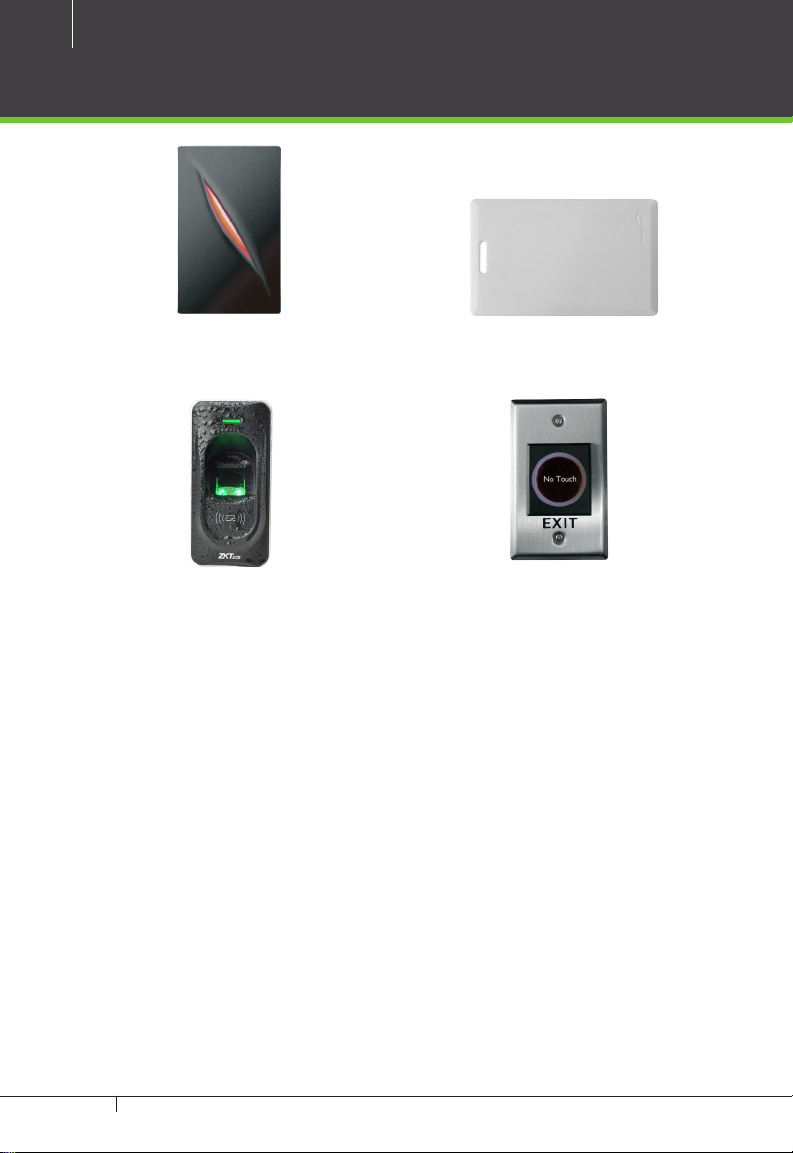
Optional accessories
Wiegand Card Reader
FR1200 FP Reader
Prox Card
K1-1 Exit Button
TF1700 & ZKAccess CLASSIC 3.5 software INSTALLATION GUIDE
Page 5
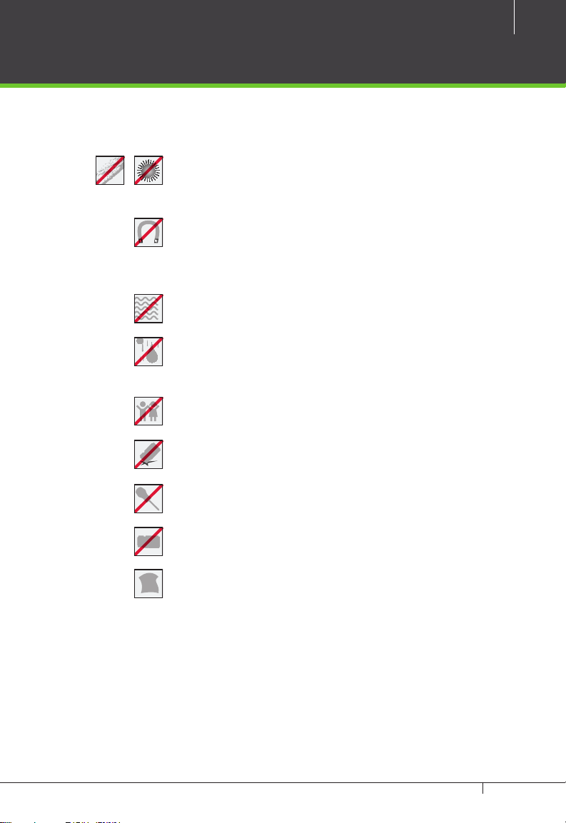
Safety Precautions
The following precautions are to keep user’s safe and prevent any damage.
Please read carefully before installation
Do not install the device in a place subject to direct sun
light, humidity, dust or soot
Do not place a magnet near the product. Magnetic objects
such as magnet, CRT, TV, monitor or speaker may damage
the device.
Do not place the device next to heating equipment
Be careful not to let liquid like water, drinks or chemicals
leak inside the device.
Do not let children touch the device without supervision
5
Do not drop or damage the device
Do not disassemble, repair or alter the device.
Do not use the device for any other purpose than specied.
Clean the device often to remove dust on it. In cleaning, do
not splash water on the device but wipe it out with smooth
cloth or towel.
Contact your supplier in case of a problem.
TF1700 & ZKAccess CLASSIC 3.5 software INSTALLATION GUIDE
Page 6
6
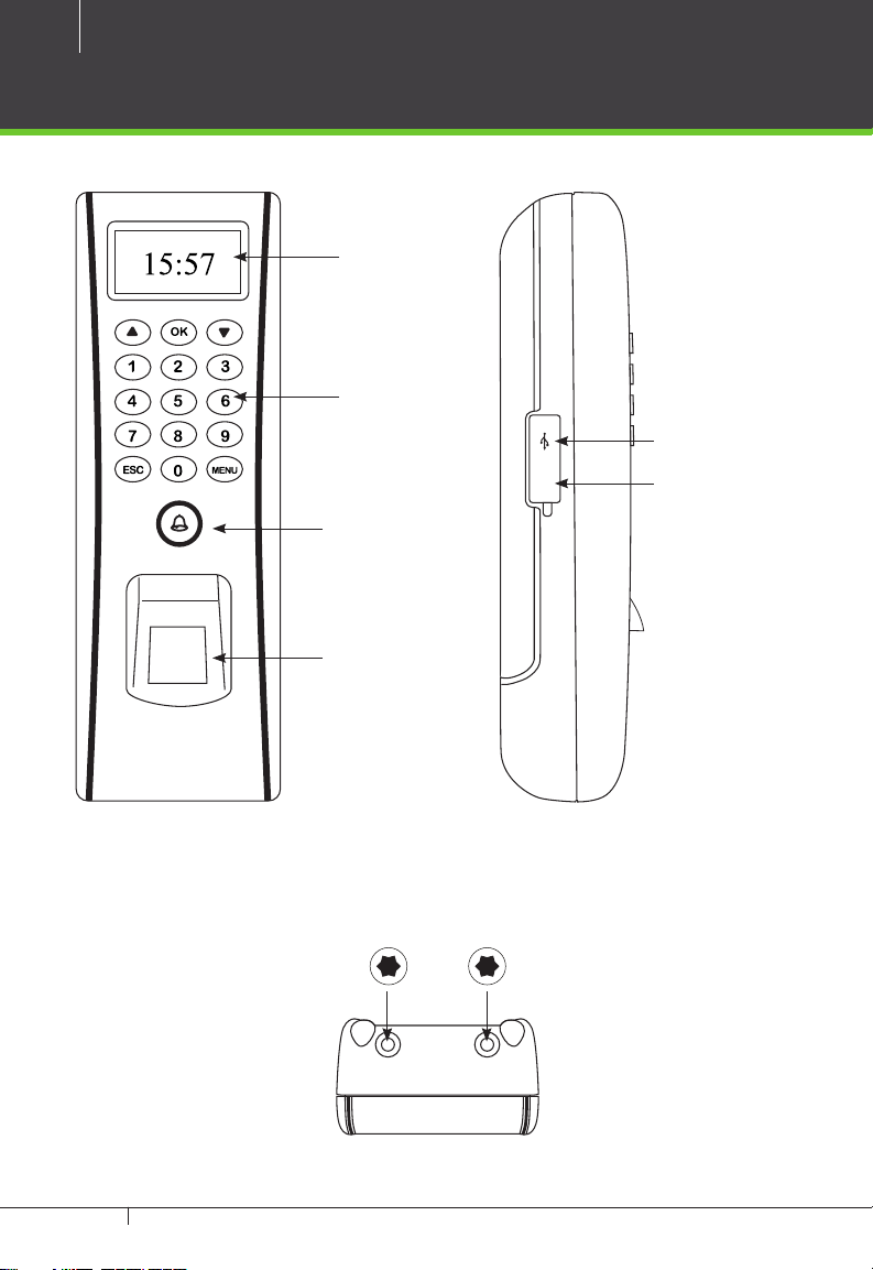
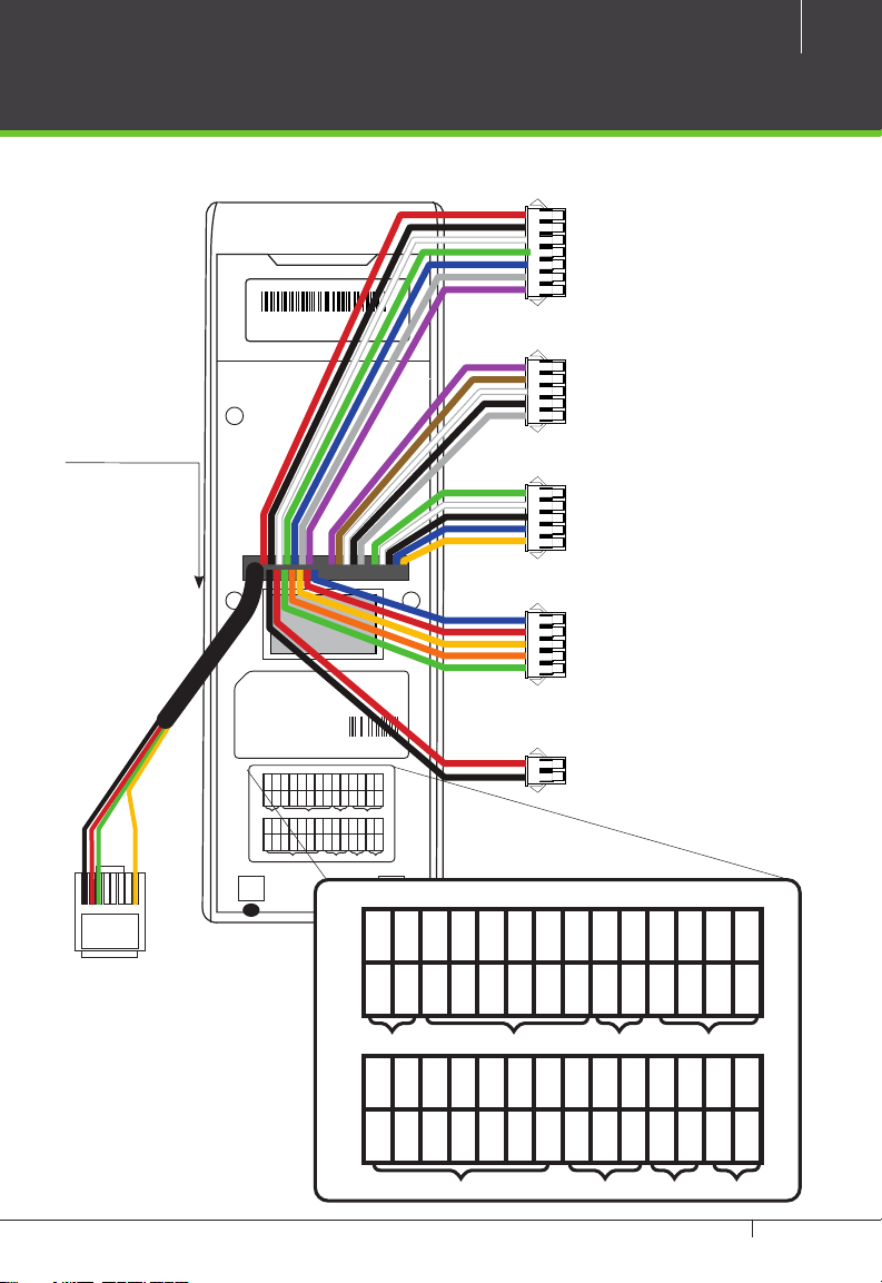
Product PIN Diagram
OLED
Display
3x5 Keypad
Reset
Door Bell &
LED Indicator
Area
ZK Optical
Sensor
Star-shaped screw hole for xing reader to the back plate
USB Host
Reset Switch
TF1700 & ZKAccess CLASSIC 3.5 software INSTALLATION GUIDE
Page 7
SN 000000000000
Fingerprint Access Control
Manufacturing license No: 75569364-2
SBTS Registered No: H0201
Power Supply DC 12V == 3A
Operating Environment Temperature: 0ºC-45ºC
ISO9000 :
2008 CE FC RoHS
69370226
7
7 pin Cable connectors
5 pin Cable connectors
5 pin Cable connectors
1234567
8
Fingerprint Access Control
Manufacturing license No: 75569364-2
SBTS Registered No: H0201
Power Supply DC 12V == 3A
Operating Environment Temperature: 0ºC-45ºC
2008 CE FC RoHS
ISO9000 :
SEN
BELL-
BELL+
White
Purple
Brown
Bell LOCK Alarm Ethernet
GND
+12V
IWD1
Red
Black
White
RJ 45
Ethernet
69370226
NO2
NO1
BUT
GND
YNC1
COM2
COM1
RJ45-1
RJ45-2
RJ45-3
RJ45-6
:::
:
Red
Blue
Gray
Black
Green
Yellow
Orange
485-
485+
GND
GND
WD0
WD1
+12V
BEEP
RLED
GLED
IWD0
Blue
Green
Red
Blue
Gray
Black
Black
Green
White
Yellow
Purple
Power485WG-OutReader
BELL-
Purple
Bell LOCK Alarm Ethernet
+12V
Red
5 pin Cable connectors
2 pin Cable connectors
BELL+
Brown
GND
Black
SEN
White
IWD1
White
GND
Black
IWD0
Green
BUT
Gray
RLED
Blue
NO1
Blue
GLED
Gray
COM1
Red
BEEP
Purple
YNC1
Yellow
WD0
Green
NO2
Orange
WD1
White
COM2
Green
GND
Black
RJ45-1
:
485+
Blue
RJ45-2
:
485-
Yellow
RJ45-3
:
+12V
Red
Power485WG-OutReader
TF1700 & ZKAccess CLASSIC 3.5 software INSTALLATION GUIDE
RJ45-6
:
GND
Black
Page 8
8
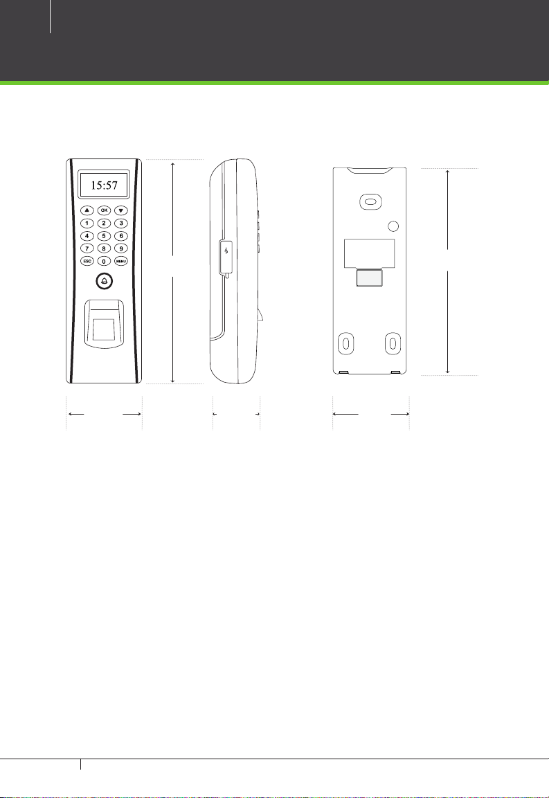
Product Dimension
2.46in
(62.5mm)
7.28in
(185mm)
Reset
1.63in
(41.5mm)
2in
(51mm)
6.125in
(153mm)
TF1700 & ZKAccess CLASSIC 3.5 software INSTALLATION GUIDE
Page 9
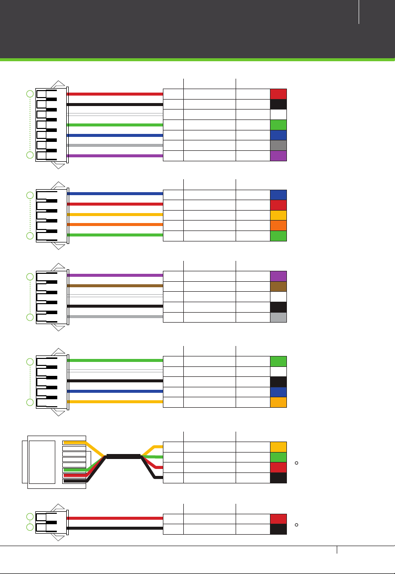
Cables and Connectors
9
1
7
1
5
1
5
1
5
PIN DESCRIPTION WIRE
1 +12V Red
2 GND Black
3 IWD1 White
4 IWD0 Green
5 RLED Blue
6 GLED Gray
7 BEEP Purple
PIN DESCRIPTION WIRE
1 NO1 Blue
2 COM1 Red
3 NC1 Yellow
4 NO2 Orange
5 COM2 Green
PIN DESCRIPTION WIRE
1 BELL- Purple
2 BELL+ Brown
3 SEN White
4 GND Black
5 BUT Gray
PIN DESCRIPTION WIRE
1 WD0 Red
2 WD1 White
3 GND Black
4 485+ Blue
5 485- Yellow
1
2
RJ 45
1
2
3
4
5
6
7
8
PIN DESCRIPTION WIRE
1 RJ45-1 Yellow
2 RJ45-2 Green
3 RJ45-3 Red
4 RJ45-6 Black
PIN DESCRIPTION WIRE
1 12V DC Red
2 GND Black
TF1700 & ZKAccess CLASSIC 3.5 software INSTALLATION GUIDE
•
•
TCP/IP
Power In
Page 10
10
TF1700
Stick this mounting paper to the wall
or door frame. Drill the holes according
to the mounting paper.
Reset
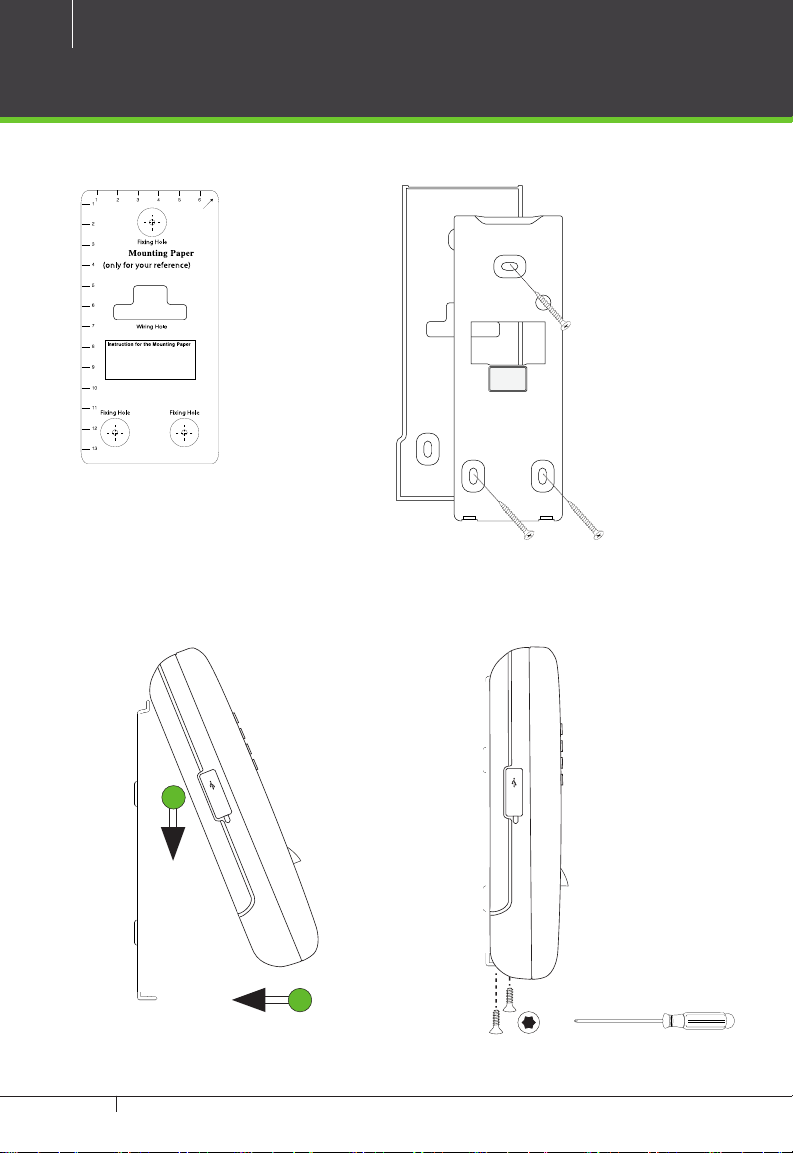
Mounting the reader on the wall
Fix back plate to the wall using wall mounting screws
1. Stick the mounting
template on the wall
and make holes as
per the markings.
2. Mount the rubber gasket
and the back plate on the
wall with the help of the
supplied screws.
We recommend drilling the mounting plate screws into solid wood (i.e. stud/beam). If a stud/beam
cannot be found, then use the supplied drywall plastic mollies (anchors).
1
Reset
2
4. Use star-shaped screw to mount it3. Inserting Reader to backplate
TF1700 & ZKAccess CLASSIC 3.5 software INSTALLATION GUIDE
Page 11
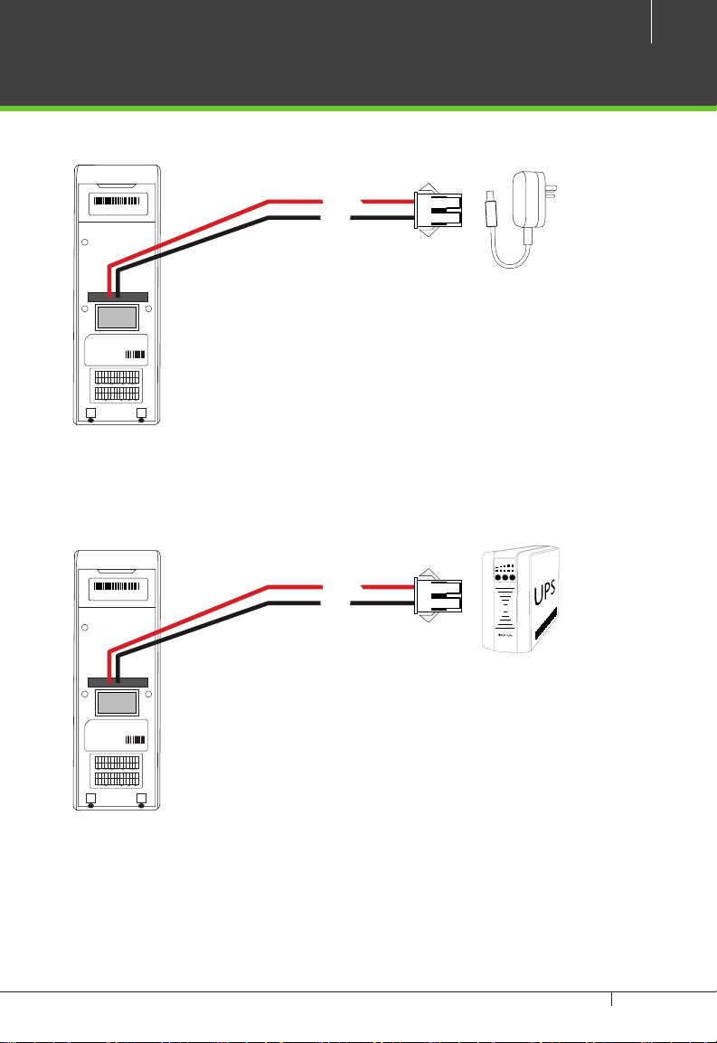
Power Connection
11
Without UPS
SN 000000000000
Fingerprint Access Control
Manufacturing license No: 75569364-2
SBTS Registered No: H0201
Power Supply DC 12V == 3A
Operating Environment Temperature: 0ºC-45ºC
2008 CE FC RoHS
ISO9000 :
SEN
NO1
BUT
GND
BELL-
BELL+
Blue
Gray
Black
White
Purple
Brown
Bell LOCK Alarm Ethernet
GND
+12V
RLED
GLED
IWD1
IWD0
Red
Blue
Gray
Black
Green
White
12V DC
GND
12V DC Adaptor
69370226
NO2
YNC1
COM2
COM1
RJ45-1
RJ45-2
RJ45-3
RJ45-6
:::
:
Red
Green
Yellow
Orange
485-
485+
GND
GND
WD0
WD1
+12V
BEEP
Red
Blue
Black
Black
Green
White
Yellow
Purple
Power485WG-OutReader
With UPS (Optional)
12V DC
GND
12V DC Adaptor
69370226
NO2
YNC1
COM2
COM1
RJ45-1
RJ45-2
RJ45-3
RJ45-6
:::
:
Red
Green
Yellow
Orange
485-
485+
GND
GND
WD0
WD1
+12V
BEEP
Red
Blue
Black
Black
Green
White
Yellow
Purple
Power485WG-OutReader
Recommended power supply
•Regulated 12V DC, 1A.
•Comply with standard IEC/EN 60950-1.
• To share the power with other devices, use a power supply with higher current ratings
TF1700 & ZKAccess CLASSIC 3.5 software INSTALLATION GUIDE
Page 12
12
+
+
+
BUTTON BUTTONREADER 1 READER 2BUTTON BUTTONREADER 1 READER 2
RX
TX
RX
POWER
RUN CARD
485-
485+
IN
GND
BEEP
GLED
WD1
WD0
GND
+12V
BUTTON READER
IN
GND
BEEP
GLED
WD1
WD0
GND
+12V
BUTTON READER
IN
GND
BEEP
GLED
WD1
WD0
GND
+12V
BUTTON READER
NO
COM
NC
AUXOUT1
NO
COM
NC
AUXOUT2
NO
COM
NC
AUXOUT3
NO
COM
NC
V+V-12V
GND
AUXOUT4
SEN
GNDNOCOM
NC
LOCK1
SEN
GNDNOCOM
NC
LOCK2
SEN
GNDNOCOM
NC
LOCK3
SEN
GNDNOCOM
NC
LOCK4 LOCK POWER
IN
GND
BEEP
GLED
WD1
WD0
GND
+12V
BUTTON READER
+
+
+
BUTTON BUTTONREADER 1 READER 2BUTTON BUTTONREADER 1 READER 2
RX
TX
RX
POWER
RUN CARD
485-
485+
IN
GND
BEEP
GLED
WD1
WD0
GND
+12V
BUTTON READER
IN
GND
BEEP
GLED
WD1
WD0
GND
+12V
BUTTON READER
IN
GND
BEEP
GLED
WD1
WD0
GND
+12V
BUTTON READER
NO
COM
NC
AUXOUT1
NO
COM
NC
AUXOUT2
NO
COM
NC
AUXOUT3
NO
COM
NC
V+V-12V
GND
AUXOUT4
SEN
GNDNOCOM
NC
LOCK1
SEN
GNDNOCOM
NC
LOCK2
SEN
GNDNOCOM
NC
LOCK3
SEN
GNDNOCOM
NC
LOCK4 LOCK POWER
IN
GND
BEEP
GLED
WD1
WD0
GND
+12V
BUTTON READER
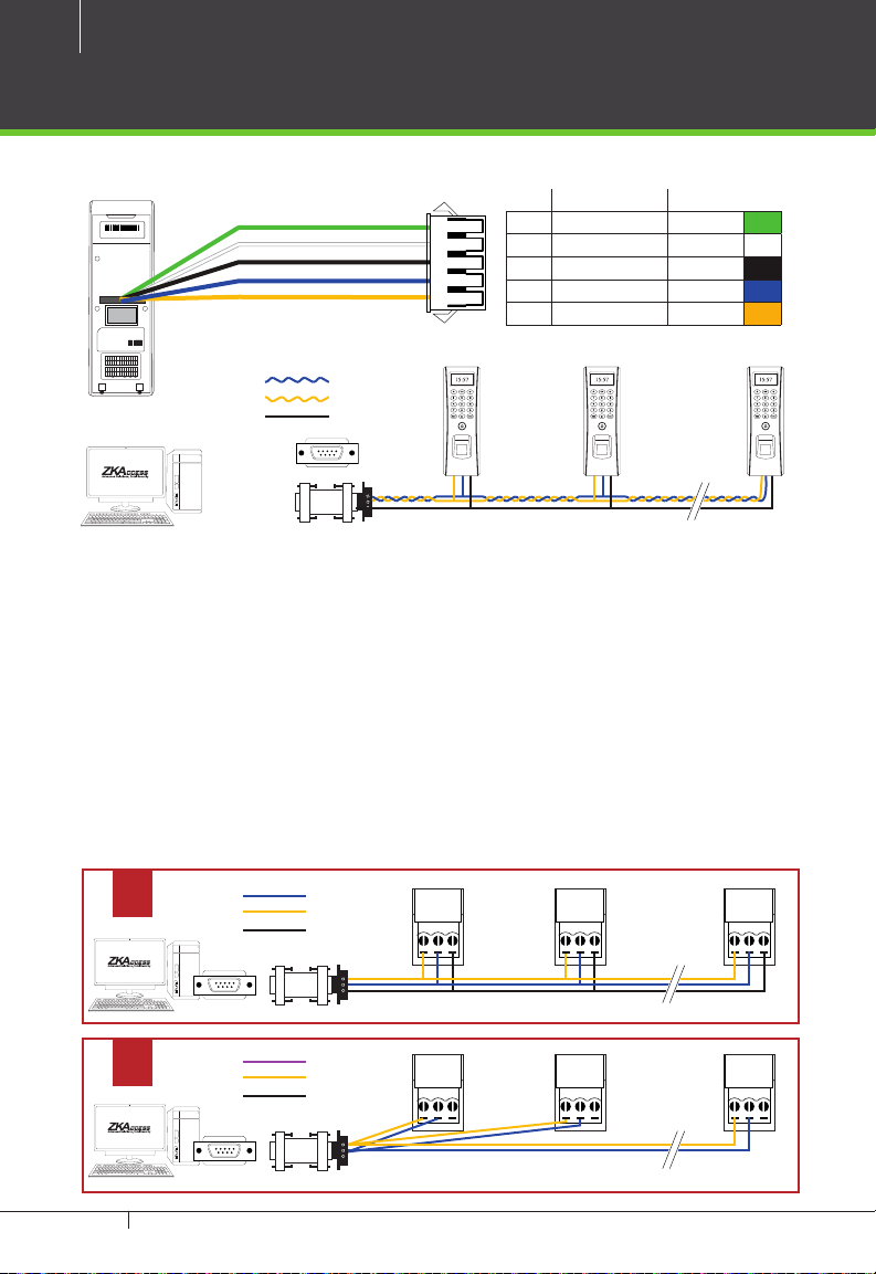
RS485 Connection
PC Connection
PIN DESCRIPTION WIRE
SN 000000000000
Fingerprint Access Control
Manufacturing license No: 75569364-2
SBTS Registered No: H0201
Power Supply DC 12V == 3A
Operating Environment Temperature: 0ºC-45ºC
69370226
2008 CE FC RoHS
ISO9000 :
SEN
NO2
NO1
BUT
GND
YNC1
BELL-
COM2
COM1
RJ45-1
RJ45-2
RJ45-3
RJ45-6
BELL+
:::
:
Red
Blue
Gray
Black
Green
White
Yellow
Purple
Brown
Orange
Bell LOCK Alarm Ethernet
485-
485+
GND
GND
GND
WD0
WD1
+12V
+12V
BEEP
RLED
GLED
IWD1
IWD0
Red
Red
Blue
Blue
Gray
Black
Black
Black
Green
Green
White
White
Yellow
Purple
Power485WG-OutReader
RS485 -RS485 +
GND
RS485
#1 TF1700 #2 TF1700 #63 TF1700
Important Notes:
1. RS485 communication wires should be a shielded and twisted pair cable.
2. RS485 communication wires should be connected in a bus cascade instead of
a star form, to achieve a better shielding eect by reducing signal reection
during communications.
3. Adjust the communication speed as needed. The signal quality vary depend-
ing on wiring conditions, and it maybe necessary to lower the baudrates.
4. The GND Signal may be omitted if and only if the GND potential dierence is
less than ±5V
Incorrect RS 485 connections
x
RS485 -RS485 +
GND
485+
485--
GND
PC
1 WD0 Red
2 WD1 White
3 GND Black
4 485+ Blue
5 485- Yellow
485+
485--
PC
GND
485+
485--
GND
PC
RS485
#1 TF1700
x
RS485 -RS485 +
GND
RS485
TF1700 & ZKAccess CLASSIC 3.5 software INSTALLATION GUIDE
#1TF1700
485+
485--
GND
PC
#2 TF1700
485+
485--
PC
#2 TF1700
GND
#63 TF1700
485+
485--
GND
PC
#63TF1700
Page 13
SN 000000000000
Fingerprint Access Control
Manufacturing license No: 75569364-2
SBTS Registered No: H0201
Power Supply DC 12V == 3A
Operating Environment Temperature: 0ºC-45ºC
2008 CE FC RoHS
ISO9000 :
SEN
BUT
GND
BELL-
BELL+
Gray
Black
White
Purple
Brown
Bell LOCK Alarm Ethernet
GND
+12V
RLED
IWD1
IWD0
Red
Blue
Black
Green
White
TF1700
13
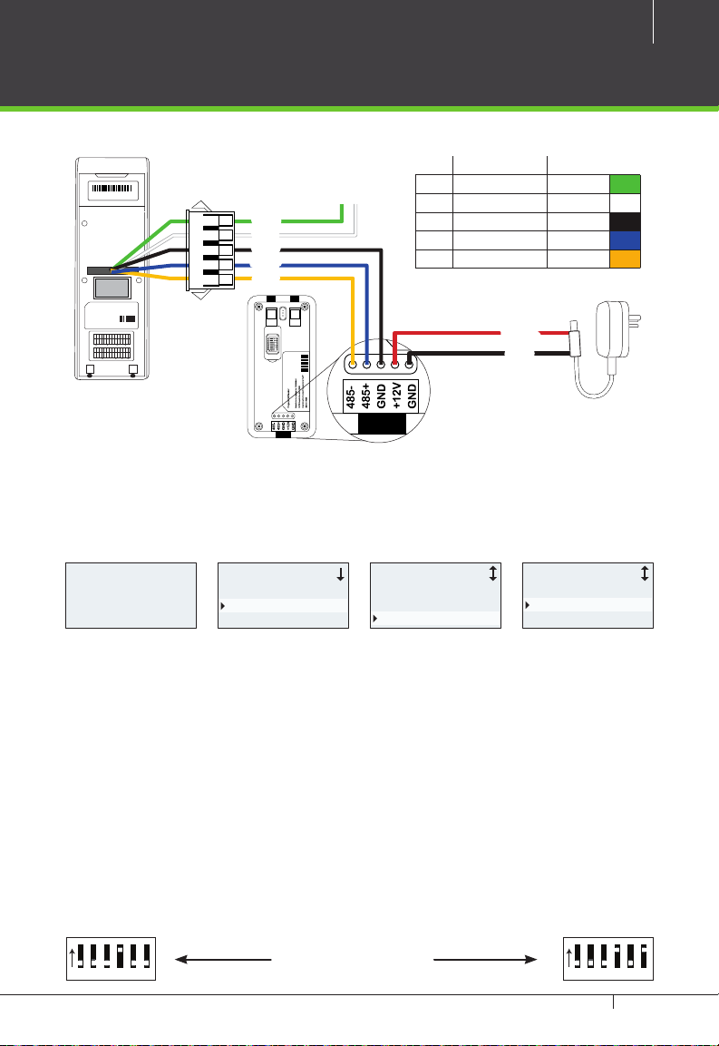
FR1200 Connection
PIN DESCRIPTION WIRE
Weigand Out
WD0
WD1
GND
485+
485-
69370226
NO2
NO1
YNC1
COM2
COM1
RJ45-1
RJ45-2
RJ45-3
RJ45-6
:::
:
Red
Blue
Green
Yellow
Orange
485-
485+
GND
GND
WD0
WD1
+12V
BEEP
GLED
Red
Blue
Gray
Black
Black
Green
White
Yellow
Purple
Power485WG-OutReader
FR1200
TF1700 Settings
1 WD0 Red
2 WD1 White
3 GND Black
4 485+ Blue
5 485- Yellow
12V DC
GND
Welcome
13:04
15-01-21 WED
Menu
User Manage
Options
PenDrive Mng
Options Access Options
Power Mng
Comm Opt
Access Options
DSen. Mode NO
485ReaderMaster
MasterState Out
1. Steps to activate the master and salve functionality between TF1700 and
FR1200 as shown in the diagram on the left.
2. There are six DIP switches on the back of FR1200, Switches 1-4 is for RS485 ad-
dress , switch 5 is reserved , switch 6 is for reducing noise on long RS485 cable.
3. If FR1200 is powered from TF1700 terminal ,the length of wire should be less
than 100 meters or 330 ft.
4. If the cable length is more than 200 meters or 600 ft. , the number 6 switch
should be ON as below
5. 5.If the 485Reader set as Salve , it will be used as inBIO-series reader , check
page 28 to know more.
ON
123456
Distance: More than 200 meters
TF1700 & ZKAccess CLASSIC 3.5 software INSTALLATION GUIDE
ON
123456
Page 14
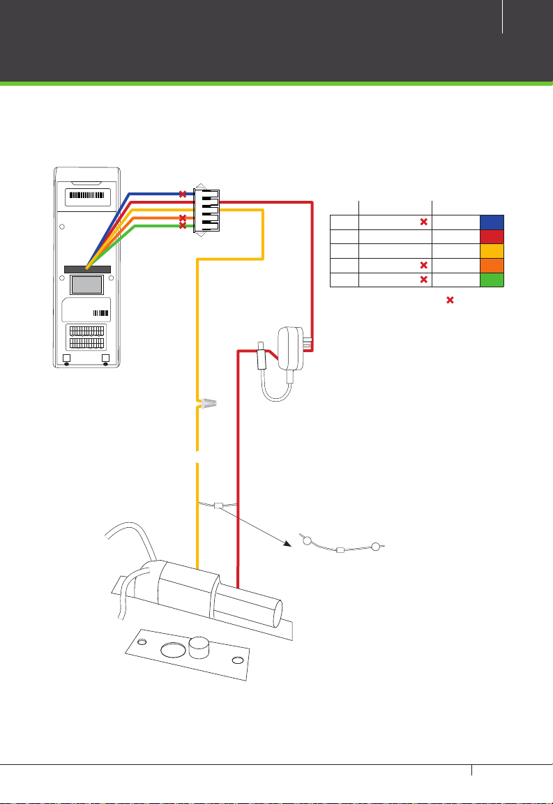
14
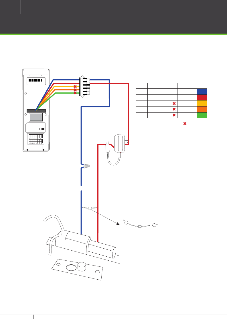
Lock Relay Connection
Normally Open Lock
SN 000000000000
Fingerprint Access Control
Manufacturing license No: 75569364-2
SBTS Registered No: H0201
Power Supply DC 12V == 3A
Operating Environment Temperature: 0ºC-45ºC
2008 CE FC RoHS
ISO9000 :
SEN
NO1
BUT
GND
BELL-
BELL+
Blue
Gray
Black
White
Purple
Brown
Bell LOCK Alarm Ethernet
GND
+12V
RLED
GLED
IWD1
IWD0
Red
Blue
Gray
Black
Green
White
PIN DESCRIPTION WIRE
1 NO1 Blue
2 COM1 Red
3 NC1 Yellow
4 NO2 Orange
5 COM2 Green
Do not use
69370226
NO2
YNC1
COM2
COM1
RJ45-1
RJ45-2
RJ45-3
RJ45-6
:::
:
Red
Green
Yellow
Orange
485-
485+
GND
GND
WD0
WD1
+12V
BEEP
Red
Blue
Black
Black
Green
White
Yellow
Purple
Power485WG-OutReader
12VDC
NO
-
FR107
Diode
+
TF1700 & ZKAccess CLASSIC 3.5 software INSTALLATION GUIDE
Page 15
Normally Closed Lock
15
SN 000000000000
Fingerprint Access Control
Manufacturing license No: 75569364-2
SBTS Registered No: H0201
Power Supply DC 12V == 3A
Operating Environment Temperature: 0ºC-45ºC
2008 CE FC RoHS
ISO9000 :
SEN
NO1
BUT
GND
BELL-
BELL+
Blue
Gray
Black
White
Purple
Brown
Bell LOCK Alarm Ethernet
GND
+12V
RLED
GLED
IWD1
IWD0
Red
Blue
Gray
Black
Green
White
PIN DESCRIPTION WIRE
1 NO1 Blue
2 COM1 Red
3 NC1 Yellow
4 NO2 Orange
5 COM2 Green
Do not use
69370226
NO2
YNC1
COM2
COM1
RJ45-1
RJ45-2
RJ45-3
RJ45-6
:::
:
Red
Green
Yellow
Orange
485-
485+
GND
GND
WD0
WD1
+12V
BEEP
Red
Blue
Black
Black
Green
White
Yellow
Purple
Power485WG-OutReader
12VDC
NC1
-
FR107
Diode
+
TF1700 & ZKAccess CLASSIC 3.5 software INSTALLATION GUIDE
Page 16

16
Aux. Input Connection
Exit Button Connection
SN 000000000000
Fingerprint Access Control
Manufacturing license No: 75569364-2
SBTS Registered No: H0201
Power Supply DC 12V == 3A
Operating Environment Temperature: 0ºC-45ºC
69370226
2008 CE FC RoHS
ISO9000 :
SEN
NO2
NO1
BUT
GND
YNC1
BELL-
COM2
COM1
RJ45-1
RJ45-2
RJ45-3
RJ45-6
BELL+
:::
:
Red
Blue
Gray
Black
Green
White
Yellow
Purple
Brown
Orange
Bell LOCK Alarm Ethernet
485-
485+
GND
GND
GND
WD0
WD1
+12V
+12V
BEEP
RLED
GLED
IWD1
IWD0
Red
Red
Blue
Blue
Gray
Black
Black
Black
Green
Green
White
White
Yellow
Purple
Power485WG-OutReader
PIN DESCRIPTION WIRE
1 BELL- Purple
2 BELL+ Brown
3 SEN White
4 GND Black
5 BUT Gray
Do not use
No Touch
EXIT
TF1700 & ZKAccess CLASSIC 3.5 software INSTALLATION GUIDE
Sensor
Page 17

Aux. Output Connection
Alarm Button Connection
SN 000000000000
Fingerprint Access Control
Manufacturing license No: 75569364-2
SBTS Registered No: H0201
Power Supply DC 12V == 3A
Operating Environment Temperature: 0ºC-45ºC
69370226
2008 CE FC RoHS
ISO9000 :
SEN
NO2
NO1
BUT
GND
YNC1
BELL-
COM2
COM1
RJ45-1
RJ45-2
RJ45-3
RJ45-6
BELL+
:::
:
Red
Blue
Gray
Black
Green
White
Yellow
Purple
Brown
Orange
Bell LOCK Alarm Ethernet
485-
485+
GND
GND
GND
WD0
WD1
+12V
+12V
BEEP
RLED
GLED
IWD1
IWD0
Red
Red
Blue
Blue
Gray
Black
Black
Black
Green
Green
White
White
Yellow
Purple
Power485WG-OutReader
17
PIN DESCRIPTION WIRE
1 NO1 Blue
2 COM1 Red
3 NC1 Yellow
4 NO2 Orange
5 COM2 Green
Do not use
ALARM
TF1700 & ZKAccess CLASSIC 3.5 software INSTALLATION GUIDE
Page 18

18
Aux. Output Connection
Door Bell Button Connection
SN 000000000000
Fingerprint Access Control
Manufacturing license No: 75569364-2
SBTS Registered No: H0201
Power Supply DC 12V == 3A
Operating Environment Temperature: 0ºC-45ºC
69370226
2008 CE FC RoHS
ISO9000 :
SEN
NO2
NO1
BUT
GND
YNC1
BELL-
COM2
COM1
RJ45-1
RJ45-2
RJ45-3
RJ45-6
BELL+
:::
:
Red
Blue
Gray
Black
Green
White
Yellow
Purple
Brown
Orange
Bell LOCK Alarm Ethernet
485-
485+
GND
GND
GND
WD0
WD1
+12V
+12V
BEEP
RLED
GLED
IWD1
IWD0
Red
Red
Blue
Blue
Gray
Black
Black
Black
Green
Green
White
White
Yellow
Purple
Power485WG-OutReader
PIN DESCRIPTION WIRE
1 BELL- Purple
2 BELL+ Brown
3 SEN White
4 GND Black
5 BUT Gray
Do not use
TF1700 & ZKAccess CLASSIC 3.5 software INSTALLATION GUIDE
Page 19

Weigand Input Connection
RFID Button Connection
SN 000000000000
Fingerprint Access Control
Manufacturing license No: 75569364-2
SBTS Registered No: H0201
Power Supply DC 12V == 3A
Operating Environment Temperature: 0ºC-45ºC
69370226
2008 CE FC RoHS
ISO9000 :
SEN
NO2
NO1
BUT
GND
YNC1
BELL-
COM2
COM1
RJ45-1
RJ45-2
RJ45-3
RJ45-6
BELL+
:::
:
Red
Blue
Gray
Black
Green
White
Yellow
Purple
Brown
Orange
Bell LOCK Alarm Ethernet
485-
485+
GND
GND
GND
WD0
WD1
+12V
+12V
BEEP
RLED
GLED
IWD1
IWD0
Red
Red
Blue
Blue
Gray
Black
Black
Black
Green
Green
White
White
Yellow
Purple
Power485WG-OutReader
19
PIN DESCRIPTION WIRE
1 +12V Red
2 GND Black
3 IWD1 White
4 IWD0 Green
5 RLED Blue
6 GLED Gray
7 BEEP Purple
Do not use
TF1700 & ZKAccess CLASSIC 3.5 software INSTALLATION GUIDE
Page 20

20
IN
GND
IN
GND
IN
GND
IN
GND
+12V
GND
485-
485+
IN
GND
IN
GND
IN
GND
IN
GND
+12V
GND
485-
485+
AUX 1 AUX 2 AUX 3 AUX4 EXT STATE BUTTON 1 READER 1 BUTTON 2 READER 2 BUTTON 3 READER 3 BUTTON 4 READER 4AUX 1 AUX 2 AUX 3 AUX4 EXT STATE BUTTON 1 READER 1 BUTTON 2 READER 2 BUTTON 3 READER 3 BUTTON 4 READER 4
PWR
RUN
ACT
GRD
IN
GND
BEEP
GLED
WD1
WD0
GND
+12V
PWR
RUN
ACT
GRD
IN
GND
BEEP
GLED
WD1
WD0
GND
+12V
Weigand Output Connection
LANLAN
SWITCHSWITCH PCPC AUXOUT1AUXOUT1 AUXOUT2AUXOUT2 AUXOUT3AUXOUT3 AUXOUT4AUXOUT4 LOCK1LOCK1 LOCK2LOCK2 LOCK3LOCK3 LOCK4LOCK4 LOCKLOCK POWERPOWER
485+
485+
485-
485-
SGND
SGND
NO
NO
COM
COM
NC
NC
NO
NO
COM
COM
NC
NC
NO
NO
COM
COM
NC
NC
NO
NO
COM
COM
NC
NC
SEN
SEN
GND
GND
NO
NO
COM
COM
NC
NC
SEN
SEN
GND
GND
NO
NO
COM
COM
NC
NC
SEN
SEN
GND
GND
NO
NO
COM
COM
NC
NC
SEN
SEN
GND
GND
NO
NO
COM
COM
NC
NC
V+
V+
V-
V-
+12V
+12V
GND
GND
Access Control Panel
AUX 1 AUX 2 AUX 3 AUX4 EXT STATE BUTTON 1 READER 1 BUTTON 2 READER 2 BUTTON 3 READER 3 BUTTON 4 READER 4AUX 1 AUX 2 AUX 3 AUX4 EXT STATE BUTTON 1 READER 1 BUTTON 2 READER 2 BUTTON 3 READER 3 BUTTON 4 READER 4
Best Security Solution for the World Best Security Solution for the World
Adva nce d Ac cess Con tr ol
SN 000000000000
Fingerprint Access Control
Manufacturing license No: 75569364-2
SBTS Registered No: H0201
Power Supply DC 12V == 3A
Operating Environment Temperature: 0ºC-45ºC
2008 CE FC RoHS
ISO9000 :
SEN
NO1
BUT
GND
BELL-
COM1
BELL+
Red
Blue
Gray
Black
White
Purple
Brown
Bell LOCK Alarm Ethernet
GND
+12V
BEEP
RLED
GLED
IWD1
IWD0
Red
Blue
Gray
Black
Green
White
Purple
TF1700
TF1700 & ZKAccess CLASSIC 3.5 software INSTALLATION GUIDE
YNC1
Yellow
WD0
Green
RS485
RS485
EXT
EXT
RS485PCRS485
PC
CARDCARD RUNRUN POWERPOWER
69370226
NO2
COM2
Green
Orange
GND
WD1
Black
White
IN
IN
GND
GND
IN
IN
GND
GND
IN
IN
GND
GND
IN
IN
GND
GND
+12V
+12V
GND
GND
485-
485-
485+
485+
PWR
PWR
RUN
RUN
ACT
ACT
GRD
GRD
IN
IN
GND
GND
BEEP
BEEP
GLED
GLED
WD1
WD1
WD0
WD0
GND
GND
+12V
+12V
IN
IN
GND
GND
BEEP
BEEP
GLED
GLED
WD1
WD1
WD0
WD0
GND
GND
+12V
+12V
IN
IN
GND
GND
BEEP
BEEP
GLED
GLED
WD1
WD1
WD0
WD0
GND
GND
+12V
+12V
IN
IN
GND
GND
BEEP
BEEP
GLED
GLED
WD1
WD1
WD0
WD0
GND
GND
+12V
+12V
WD0
WD1
GND
485+
485-
RJ45-1
RJ45-2
RJ45-3
RJ45-6
:::
:
485-
485+
GND
+12V
Red
Blue
Black
Yellow
Power485WG-OutReader
PIN DESCRIPTION WIRE
1 WD0 Red
2 WD1 White
3 GND Black
4 485+ Blue
5 485- Yellow
Do not use
Page 21

Standalone Installation
FR1200 Connection
RS485 TCP/IP
21
RS232/485 Converter
Sensor
Lock
Switch
ALARM
No Touch
EXIT
Exit Button
TF 1700
TF1700 & ZKAccess CLASSIC 3.5 software INSTALLATION GUIDE
Page 22

22
Installation with Third Party Panels
C3 Conroller Panel Connection
Sensor Sensor
Inside InsideOutside Outside
Weigand
Output
Lock
AUX 1
AUX 2 AUX 3 AUX 4 EXT EXT
IN
GNDINGNDINGNDINGND
LINK
TCP/IP
ACT
ON
12345678
+12V
GND
485-
TX
RX
PC AUXOUT1
Lock
BUTTON READER
BUTTON READER
BUTTON READER
485+
IN
GND
BEEP
GLED
WD1
WD0
GND
+12V
IN
GND
BEEP
GLED
TX
RX
NO
COMNC485+
485--
GND
NO
COM
NC
NO
COM
NC
NO
COM
NC
SEN
GNDNOCOM
AUXOUT2
AUXOUT3
AUXOUT4
LOCK1
BUTTON READER
WD1
WD0
GND
+12V
IN
GND
BEEP
GLED
WD1
WD0
GND
+12V
IN
GND
BEEP
GLED
WD1
WD0
GND
BUTTON BUTTONREADER 1 READER 2BUTTON BUTTONREADER 1 READER 2
NC
SEN
GNDNOCOM
NC
LOCK2
+12V
+
RUN CARD
+
POWER
+
V+V-12V
NC
SEN
GNDNOCOM
NC
LOCK4 LOCK POWER
GND
SEN
GNDNOCOM
LOCK3
RS485
Switch
TF1700 & ZKAccess CLASSIC 3.5 software INSTALLATION GUIDE
RS232/485 Converter
Page 23

inBIO Conroller Panel Connection
Sensor Sensor
Inside InsideOutside Outside
23
Weigand
Output
Lock
IN
GNDINGNDINGNDINGND
+12V
GND
485-
IN
AUX 1 AUX 2 AUX 3 AUX4 EXT STATE BUTTON 1 READER 1 BUTTON 2 READER 2 BUTTON 3 READER 3 BUTTON 4 READER 4AUX 1 AUX 2 AUX 3 AUX4 EXT STATE BUTTON 1 READER 1 BUTTON 2 READER 2 BUTTON 3 READER 3 BUTTON 4 READER 4
Best Security Solution for the World Best Security Solution for the World
485+
GNDINGNDINGNDINGND
+12V
GND
485-
485+
PWR
RUN
ACT
GRDINGND
BEEP
GLED
WD1
WD0
GND
+12VINGND
BEEP
GLED
WD1
WD0
GND
PWR
RUN
ACT
GRDINGND
EXT
EXT
RS485
RS485PCRS485PCRS485
BEEP
+12VINGND
GLED
WD1
WD0
GND
+12VINGND
BEEP
GLED
WD1
WD0
GND
+12VINGND
CARDCARD RUNRUN POWERPOWER
Adva nce d Ac cess Con tr ol
SWITCHSWITCH PCPC AUXOUT1AUXOUT1 AUXOUT2AUXOUT2 AUXOUT3AUXOUT3 AUXOUT4AUXOUT4 LOCK1LOCK1 LOCK2LOCK2 LOCK3LOCK3 LOCK4LOCK4 LOCKLOCK POWERPOWER
LANLAN
485+
485-
SGNDNOCOMNCNO
COMNCNO
COMNCNO
COMNCSEN
GNDNOCOMNCSEN
COMNCNO
COMNCSEN
GNDNOCOMNCSEN
GNDNOCOMNCSEN
GNDNOCOMNCSEN
485+
485-
SGNDNOCOMNCNO
COMNCNO
BEEP
GLED
BEEP
GLED
WD1
WD0
WD1
WD0
GNDNOCOMNCSEN
GNDNOCOMNCSEN
GND
+12VINGND
GND
+12VINGND
BEEP
BEEP
GNDNOCOMNCV+V-+12V
GNDNOCOMNCV+V-+12V
TCP/IP
GLED
GLED
Lock
WD1
WD1
WD0
GND
+12V
WD0
GND
+12V
GND
GND
Switch
RS485
RS232/485 Converter
TF1700 & ZKAccess CLASSIC 3.5 software INSTALLATION GUIDE
Page 24

24
How Does TF1700 Work
Fingerprint must be registered rst
by any nger print reader
Identication
Finger Registration
Event Log Stored
Fingerprint Database
Verication failed
Please try
again !
Granted
Thank You
Door Opens
TF1700 & ZKAccess CLASSIC 3.5 software INSTALLATION GUIDE
Verication
Page 25

Troubleshooting
1. Fingerprint can not be read or it takes too long.
› Check whether a nger or ngerprint sensor is stained with sweat, water, or dust
› Retry after wiping o nger and ngerprint sensor with dry paper tissue or a mildly
wet cloth.
› If a ngerprint is way too dry, blow on the nger and retry.
2. Fingerprint is veried but authorization keeps failing.
› Check whether the user is restricted by group or time zone.
› Check with administrator whether the enrolled ngerprint has been deleted from the
device for some reason.
3. Authorized but door does not open.
› Check whether the lock open duration is set to appropriate time, which opens the lock.
› Check whether anti-passback mode is in use. In anti-passback mode, only the person
who has entered through that door can exit.
4. Why device display “system broken“ and the alarm is ringing.
› Check whether the device and back plate are securely connected to each other. If not,
a tamper switch is activated which triggers the alarm and keeps it ringing.
25
TF1700 & ZKAccess CLASSIC 3.5 software INSTALLATION GUIDE
Page 26

26
How to Place a Finger on Scanner
ZKTeco’s ngerprint readers will give optimal results for ngerprint matching
if the following recommendations and suggestions are followed.
Select a nger to enroll
• It is recommended to use an index nger or
a middle nger.
• Thumb, ring or little nger are relatively
dicult to place in the correct position
How to place a nger on a sensor
• Place a nger such that it completely covers
the sensor area with maximum contact.
• Place core of the ngerprint at the center of
the sensor. The core of a ngerprint is a center
where the spiral of ridges is dense. (Usually core
of ngerprint is the opposite side of the lower part
of a nail.)
• Place a nger such that the bottom end of a
nail is located at the center of a sensor.
TF1700 & ZKAccess CLASSIC 3.5 software INSTALLATION GUIDE
Page 27

DO NOT place the nger in the following positions
Upright
Skewed
27
If a nger is placed
as shown on the left,
only a small area of
a nger is captured.
So it is recommended
to place a nger as
shown on page 24.
Sideways
Partial
Tips for dierent ngerprint conditions
• ZKTeco’s ngerprint products are designed to verify ngerprints with highest
security irrespective of the conditions of the skin of the nger. However, in case
a ngerprint is not read on the sensor, please refer to the followings tips.
ū If a nger is stained with sweat or water, scan after wiping moisture o.
ū If a nger is covered with dust or impurities, scan after wiping them o.
ū If a nger is way too dry, please blow some warm air from your mouth on the
nger tip.
Tips for ngerprint enrollment
• In ngerprint recognition, enrollment process is very important. When enroll-
ing a ngerprint, please try to place the nger correctly with utmost care.
• In case of low acceptance ratio, the following actions are recommended.
ū Delete the enrolled ngerprint and re-enroll the nger.
ū Try another nger if a nger is not easy to enroll due to scar or cuts.
• In case of an enrolled ngerprint cannot be used due to injury or if the hand is
full, it is recommended to enroll more than two ngers per user.
TF1700 & ZKAccess CLASSIC 3.5 software INSTALLATION GUIDE
Page 28

28
Electrical Specications
Minimum
Typical
Maximum
Notes
WORKING POWER SUPPLY
Voltage (V) 9.6 12 14.4 Use regulated DC power adaptor only
Current (A) 2
ELECTRONIC LOCK RELAY OUTPUT
Switching voltage (V) 12V Use regulated DC power adaptor only
Switching Current (A) 2
SWITCH AUX. INPUT
VIH (V) TBD
VIL (V) TBD
Pull- up resistance (Ω) 4.7k
WIEGAND INPUT
Voltage (V) 10.8 12 13.5
Current (mA) 500
TTL/WIEGAND OUTPUT
VOH (V) 5
VOL (V) 0.8
Pull- up resistance (Ω) 4.7K
ZK ELECTRONIC LOCK
Voltage (V) 10.8 12 13.2
Current (mA) 500
TF1700 & ZKAccess CLASSIC 3.5 software INSTALLATION GUIDE
The input ports are pulled up with 4.7k
resistors
The outputs ports are open drain type,
pulled up with 4.7k resistors internally
Page 29

Specications
Fingerprint Capacity 3,000 ( Optional 8000 FP if with pull rmware)
Transaction capacity 100,000
Hardware Platform ZEM720
CPU ZK 6001, 400Mhz
Memory 64MB Flash, 32MB SDRAM
Fingerprint Sensor ZK optical sensor
Display 128 x 64 OLED screen
LED Indicator Red, Green
Communication Ethernet (10/100M), RS485, USB-HOST
Wiegand Signal Wiegand Input and Wiegand Output
Identication Speed ≤1 sec
29
FAR ≤0.0001%
FRR ≤1%
Operating Temperature 32º to 113º F ( 0º to 45º C)
Operating Humidity 20%-80%
Language English, Spanish, Portuguese, French, Thai...
Power Supply 12V DC, 3A
Access control interfaces Electric lock, alarm, exit button, wired door bell
Dimension W: 62.5x H: 185x D: 41.5mm ( W: 3 1/8 “x H: 7 1/4” x D: 1 5/8“)
Certied
TF1700 & ZKAccess CLASSIC 3.5 software INSTALLATION GUIDE
Page 30

30
ZKAccess CLASSIC 3.5
Installation Guide
Contents
Downloading ......................................................................... 31
Installation ...............................................................................32
Adding an Area .....................................................................33
Adding a Device...................................................................34
To add a standalone device ..................................................34
To add an Access Control Panel .......................................... 35
Creating a Time Zone ....................................................... 36
Creating an Access Level ...............................................37
Creating Departments/Enrolling Personnel ...38
Importing Personnel Data from Device ............. 40
Exporting Personnel Data to Device ..................... 41
Door Settings ......................................................................... 42
Real Time Monitoring ....................................................... 43
Exporting Reports ............................................................... 44
Passage Mode ........................................................................45
First-Card Normal Open .................................................46
TF1700 & ZKAccess CLASSIC 3.5 software INSTALLATION GUIDE
Page 31

Downloading
2
1. Go to zkaccess.com
2. Hover over Downloads then click Software Downloads in the dropdown menu.
3
3. Scroll to the bottom of the page and click ZKACCESS CLASSIC 3.5 to download
If you do not have software to extract compressed les, Scroll up on the
same page to nd Winrar 32 or Winrar 64 to download
31
4. Extract Files to a Setup Folder
5. Open the setup folder and run
setup.exe to install
5
TF1700 & ZKAccess CLASSIC 3.5 software INSTALLATION GUIDE
Page 32

32
Installation
1
1. Click Next until asked to choose a path for storing backup les
2 2
2 3
2. Click Browse and Make New Folder , now click OK
3. Click Next and then Install
TF1700 & ZKAccess CLASSIC 3.5 software INSTALLATION GUIDE
Page 33

Adding an Area
Before adding devices, it is required to add an area to manage devices. The
system, by default, has set an area named Area Name and Area ID [1] .
2
1
1. Click Area
2. Click Add
33
3
4
5
6
3. Input the Area Name,
4. Area Code (Unique ID number up to 8 digit)
5. Choose a Parent Area from the dropdown menu
6. Click OK
TF1700 & ZKAccess CLASSIC 3.5 software INSTALLATION GUIDE
Page 34

34
Adding a Device
To add a standalone device:
1
2
1. Click Device
2. Click Add
3
4
5
6
7
3. Input a Device Name
4. For Access Control Panel Type, select [Standalone SDK Machine]
5. Choose an Area
6. Input the device’s IP Address
7. Click OK
TF1700 & ZKAccess CLASSIC 3.5 software INSTALLATION GUIDE
Page 35

To add an Access Control Panel:
1
1. Click Search Access Control Panels , to show the Search interface, supports
Ethernet and RS485 search.
3
223
2. Click Search , and it will prompt [Please wait……];
3. Click the device you wish to add. Click Add Device
35
4
4
4
5
4. Input a device name, type, and area.
5. Click OK
TF1700 & ZKAccess CLASSIC 3.5 software INSTALLATION GUIDE
Page 36

36
Creating a Time Zone
Time Zones are used to set when readers will be active, when doors will be open,
and when specied users will have access to specied doors.
1
1. Click Access levels > Add to enter Add access levels edit interface;
2
3
2. Input a Time Zone Name
3. Click and drag in each day’s frame to set up to three intervals per day or holiday
TF1700 & ZKAccess CLASSIC 3.5 software INSTALLATION GUIDE
Page 37

Creating an Access Level
Access levels means in a specic time period, which door or door combination
can be opened through verication
1
1
1. Click Access levels > Add
2
37
2
2
2. Set the access level name, time zone, doors, and personnel that will have access.
3. Click OK to complete setting and quit
TF1700 & ZKAccess CLASSIC 3.5 software INSTALLATION GUIDE
Page 38

38
Creating Departments / Enrolling Personnel
Before managing Personnel it is required to describe the company’s
departmental organization.
Creating Departmets
1
1
1. Click Department > Add to create Departments.
2. Input department name and de-
partment number. Choose parent
department. Then click OK
2
2
2
Enrolling Personnel
1
1
1. Click Personnel > Add to show personnel prole edit interface
TF1700 & ZKAccess CLASSIC 3.5 software INSTALLATION GUIDE
2
Page 39

39
2
5
6
3
4
8
2. Enter a Personnel Number. It cannot exceed 9 digits.
3. Select a department from the pull-down menu
4. (Optional) Enter a card number manually or using a card issuer.
5. (Optional) Enter a password for readers with keypad
6. (Optional) Click USB Sensor to enroll ngerprints.
7. Select a nger and press on the sensor three
times. When you see “Succeed in ngerprint
registration” Click OK
9
7
9
8. (Optional) Register employee as Administrator through [Terminal Management]
9. Click the Alternative Access Levels tab choose the user’s Access Level. Click OK
TF1700 & ZKAccess CLASSIC 3.5 software INSTALLATION GUIDE
Page 40

40
Importing Personnel Data from Device
1. Click Device . Choose a device to import personnel from.
Get Personnel Data From Device to import from device
1
2
2. Choose Personnel, Fingerprints, or Face Templates to download, click Get
TF1700 & ZKAccess CLASSIC 3.5 software INSTALLATION GUIDE
Page 41

Exporting Personnel Data to Device
1
1. To export personnel data to another device, go to Access levels > Edit
2
2. Add the personnel and device to an access level. Click OK
41
3. Go to Device , choose a device
to export the personnel to, and
click Sync All Data To Device
4. Click Synchronize .
3
4
TF1700 & ZKAccess CLASSIC 3.5 software INSTALLATION GUIDE
Page 42

42
Door Settings
1
1. Click Door Setting , select the door to be modied, click Edit
3
3
3
3
2
3
3
2. Set the verication mode desired for the door.
3. (Optional) Modify the Door’s name, active time zone, passage mode, sensor
type, lock open duration, and duress settings.
TF1700 & ZKAccess CLASSIC 3.5 software INSTALLATION GUIDE
Page 43

Real Time Monitoring
Monitor the statuses and real-time events of doors under the access control
panels in the system in real-time.
1
1. Click Real-Time Monitoring to view live events
43
2. Right click on the door icon to
remote open/close.
3. Choose door open time or Enable Intraday Passage Mode
4. Choose close door or Disable Intraday Passage Mode
TF1700 & ZKAccess CLASSIC 3.5 software INSTALLATION GUIDE
2
Page 44

44
Exporting Reports
3
1
2
1. Click Reports to access transaction logs
2. Set lters to examine desired transactions, click Search
3. Click Export to export reports in XLS, PDF, or TXT le format
TF1700 & ZKAccess CLASSIC 3.5 software INSTALLATION GUIDE
Page 45

Passage Mode
The Passage Mode feature will keep a door unlocked during a specied time zone.
It will automatically unlock at the beginning of the time zone and will lock automatically at the end of the specied time zone.
1
1. Create a new Time Zone with the hours you want the door to be unlocked.
2
45
2. In Door Settings, Click Edit to change door settings.
3
3. Click the dropdown menu titled “Door Passage Mode Time Zone” and select
your new time zone
TF1700 & ZKAccess CLASSIC 3.5 software INSTALLATION GUIDE
Page 46

46
First-Card Normal Open
The First Card Normal Open feature will keep a door unlocked during a specied
time zone when triggered by specied personnel. After a reader has been used by
a specied personnel that day, the door will unlock automaticcally at the beginning of the time zone and lock again at the end of the specied time zone.
3
2
1. Create a new time zone with the hours you want the door to be unlocked.
2. Select the First-Card Normal Open Menu
3. Click Setting
4
6
4. Click Add Door
5. Choose the door you want to set to normal open and the time frame it will be
unlocked. Click OK
6. Select the door and click Add Personnel
7
7
8
7. Select Personnel and use the arrow buttons to move them to the Selected
personnel panel.
8. Click OK
Design and Specications subject to change without notice. © 2015 ZKTeco and its subsidiaries.
TF1700 & ZKAccess CLASSIC 3.5 software INSTALLATION GUIDE
Page 47

47
TF1700 & ZKAccess CLASSIC 3.5 software INSTALLATION GUIDE
Page 48

ZKAccess - a division of ZKTeco
Version: March 2015
 Loading...