

Zinwell ZWA-G880 User Manual

1
Wireless LAN Device Series
Multi-Mode AP
ZWA-G880 User’s Manual

2
T A BLE OF C ONTENTS
NOTICE..................................................................................................................................................4
PREFACE ...............................................................................................................................................6
CH 1. ZWA-G880 INSTALLATION....................................................................................................7
PACKING LIST .......................................................................................................................................7
BACK PANEL CONNECTIONS .................................................................................................................7
HARDWARE INSTALLATION..................................................................................................................8
CH 2. FIRST TIME CONFIGURATION ............................................................................................9
BEFORE START TO CONFIGURE .............................................................................................................9
KNOWING THE NETWORK APPLICATION ...............................................................................................9
BASIC SETTINGS.................................................................................................................................29
ADVANCED SETTINGS.........................................................................................................................32
CONFIGURING WIRELESS SECURITY...................................................................................................35
CONFIGURING AS WLAN CLIENT ADAPTER.......................................................................................38
QUICK START TO CONFIGURE..............................................................................................................38
MAC CLONE FOR SINGLE ETHERNET CLIENT ....................................................................................40
EXTEND THE REMOTE AP (BSS).........................................................................................................41
CH 3. CONFIGURING WDS..............................................................................................................43
WDS NETWORK TOPOLOGY................................................................................................................43
WDS APPLICATION.............................................................................................................................45
CH 4. ADVANCED CONFIGURATIONS.........................................................................................47
CONFIGURING LAN TO WAN FIREWALL ............................................................................................47
PORT FILTERING .................................................................................................................................47
IP FILTERING ......................................................................................................................................48
MAC FILTERING.................................................................................................................................49
NAT (NETWORK ADDRESS TRANSLATION).........................................................................................50
CONFIGURING POR T FORWARDING (VIR TUAL SER VER)..............................................................................51
MULTIPLE SERVERS BEHIND NAT EXAMPLE: ..................................................................................... 51
CONFIGURING DMZ...........................................................................................................................52
CONFIGURING VPN............................................................................................................................53
CONFIGURING WAN INTERFACE.........................................................................................................55
STATIC IP............................................................................................................................................55
DHCP CLIENT (DYNAMIC IP).............................................................................................................56
PPPOE................................................................................................................................................57
PPTP..................................................................................................................................................58
CONFIGURING CLONE MAC ADDRESS ...............................................................................................60

3
C
ONFIGURING DHCP SERVER ............................................................................................................62
BANDWIDTH CONTROL.......................................................................................................................63
QOS (QUALITY OF SERVICE)...............................................................................................................63
STATIC ROUTE SETUP .........................................................................................................................67
DYNAMIC ROUTE SETUP ....................................................................................................................68
VPN PASS-THROUGH..........................................................................................................................69
USING CLI MENU...............................................................................................................................69
THE SYSTEM MANAGEMENT ..............................................................................................................71
SNMP AGENT ....................................................................................................................................71
MISCELLANEOUS SETTINGS................................................................................................................74
PING WATCH DOG ...............................................................................................................................75
AIMING TOOL.....................................................................................................................................76
CONNECTING PROFILE........................................................................................................................77
FIRMWARE UPGRADE .........................................................................................................................78
CONFIGURATION DATA BACKUP & RESTORE......................................................................................79
AUTO DISCOVERY TOOL.....................................................................................................................80

4
Notice
FCC Warning
Changes or modifications to this unit not expressly approved by the party
responsible for compliance could void the user authority to operate the
equipment.
This device complies with Part 15 of the FCC Rules. Operation is subject to the
following two conditions: (1) This device may not cause harmful interference,
and (2) this device must accept any interference received, including
interference that may cause undesired operation.
The user’s manual or instruction manual for an intentional or unintentional
radiator shall caution the user that changes or modifications not expressly
approved by the party responsible for compliance could void the user’s
authority to operate the equipment.
FCC Statement
This equipment has been tested and found to comply with the limits for a Class
B digital device, pursuant to Part 15 of the FCC Rules. These limits are
designed to provide reasonable protection against harmful interference in a
residential installation. This equipment generates uses and can radiate radio
frequency energy and, if not installed and used in accordance with the
instructions, may cause harmful interference to radio communications.
However, there is no guarantee that interference will not occur in a particular
installation. If this equipment does cause harmful interference to radio or
television reception, which can be determined by turning the equipment off and
on, the user is encouraged to try to correct the interference by one or more of
the following measures:
z Reorient or relocate the receiving antenna.
z Increase the separation between the equipment and receiver.
z Connect the equipment into an outlet on a circuit different from that to
which the receiver is connected.
z Consult the dealer or an experienced radio/TV technician for help.
FCC RF Radiation Exposure Statement
This equipment complies with FCC radiation exposure limits set forth for an
uncontrolled environment. This equipment should be installed and operated
with minimum distance 20cm between the radiator & your body. For product
available in the USA/Canada market, only channel 1~11 can be operated.

5
Selection of other channels is not possible. The antenna(s) used for this
transmitter must not be co-located or operating in conjunction with any other
antenna or transmitter. Shielded interface cables must be used in order to
comply with emission limits.
CE Statement
Hereby, ZINWELL, declares that this device is in compliance with the essential
requirement and other relevant provisions of the R&TTE Directive 1999/5/EC.
This device will be sold in the following EEA countries:Austria, Italy, Belgium,
Liechtenstein, Denmark, Luxembourg, Finland, Netherlands, France, Norway,
Germany, Portugal, Greece, Spain, Iceland, Sweden, Ireland, United Kingdom,
Cyprus, Czech Republic, Estonia, Hungary, Latvia, Lithuania, Malta, Slovakia,
Poland, Slovenia, Bulgaria, Romania.

6
Preface
This guide is for the networking professional who installs and manages the
Zinwell ZWA-G880 product hereafter referred to as the “device”. To use this
guide, you should have experience working with the TCP/IP configuration and
be familiar with the concepts and terminology of wireless local area networks.
7
Ch 1. ZWA-G880 Installation
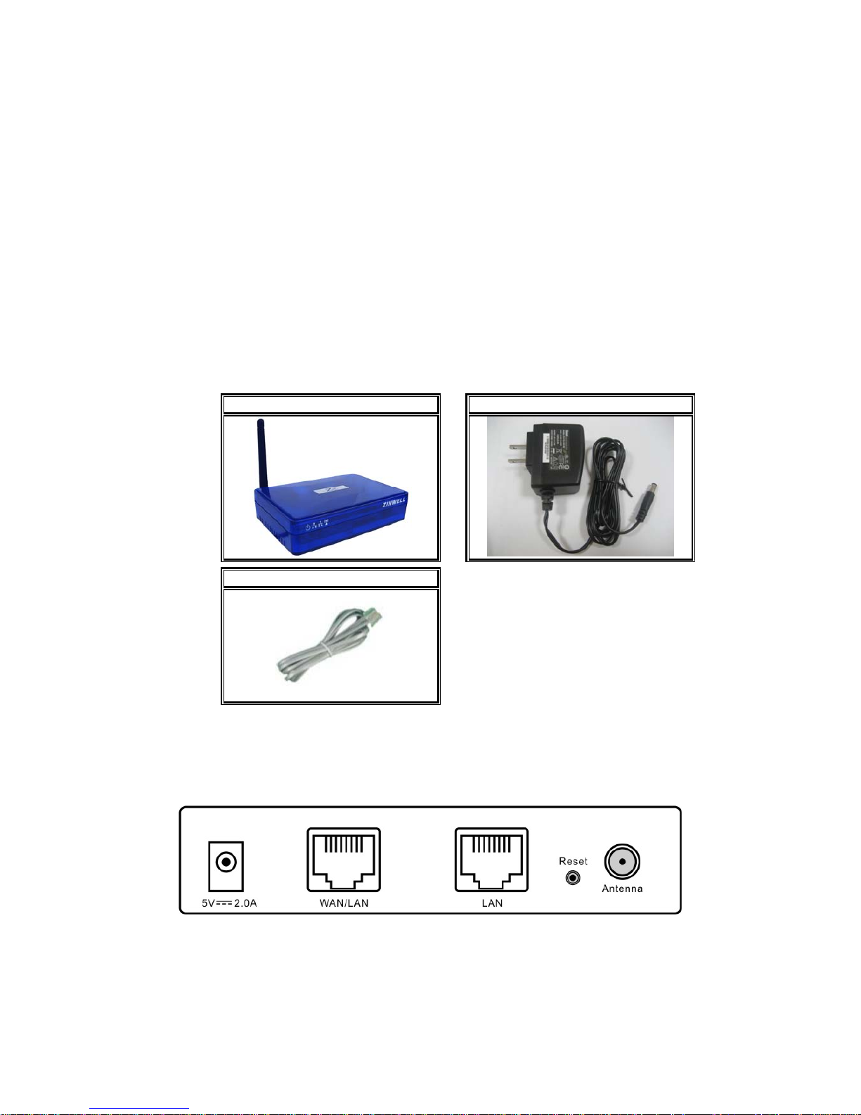
Packing List
Before you start to install the device, make sure the package contains the
following items:
● ZWA-G880 Multi-Mode AP unit * 1
● Power Adapter * 1
● RJ-45 Cable * 1
Multi-Mode AP Power Adapter
RJ-45 Cable
Back panel connections
From Left to Right:
DC jack: ZWA-G880 can use power source in DC jack. Please supply the
power in 5V and 2A
WAN/LAN: This port could be WAN or LAN port depending on the
8
configuration. It will be WAN port in router mode and LAN port in
bridge mode.
LAN: This port is always LAN in ZWA-G880. In Bridge mode, it bridges to
WLAN and “WAN/LAN” port. In Router mode, it bridges to WLAN only, In
WISP mode, it bridges to “WAN/LAN” port only.
Reset: Press Reset button to revert it to factory default.
Antenna: This SMA Reverse allows the user to connect antenna or RF cable.
At least connect an antenna to help ZWA-G880 to send and receive
RF signal.
ZWA-G880 integrates LNA/PA (Low Noise Amplifier) module and has
at lease 3dB RF sensitivity better than the regular WLAN products.
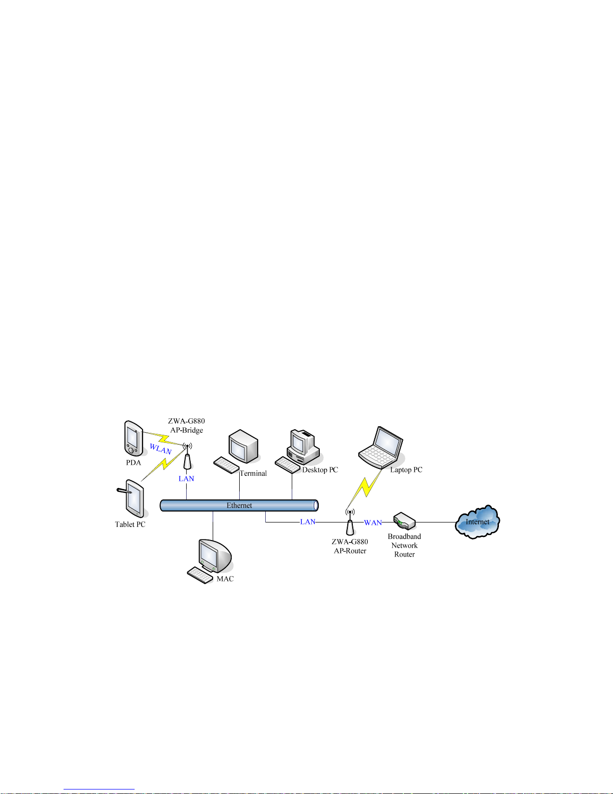
Hardware Installation
Once you check off everything from the package, you can start to install the
device. You can use the wall mount hole on the bottom of the device to
mount the device on the wall, or just put the device on the desktop. The
administrator can refer to the figure below while constructing your WLAN
environment.
W
L
A
N

9
Ch 2. First Time Configuration
Before Start to Configure
There are two ways to configure the device, one is through web-browser,
and the other is through Secure Shell CLI interface. To access the
configuration interfaces, make sure you are using a computer connected to
the same network as the device. The default IP address of the device is
192.168.2.254, and the subnet-mask is 255.255.255.0.
The device has three operation modes (Router/Bridge/WISP). In bridge
mode, also known as AP Client, you can access the device by WLAN
(Wireless Local Area Network) and both wired LAN ports. And in
router/WISP modes, the device can be accessed by WLAN, LAN and WAN.
The default IP addresses for the device are 192.168.2.254 (for LAN),
172.1.1.1(for WAN), so you need to make sure the IP address of your PC is
in the same subnet as the device, such as 192.168.2.X (for LAN), 172.1.1.X
(for WAN).
Please note that the DHCP server inside the device is default to up and
running. Do not have multiple DHCP servers in your network environment,
otherwise it will cause abnormal situation.
We also provide an auto-discovery tool which is for finding out the IP of the
device. In case, you’ve forgot the IP of the device or the IP of the device has
been changed, you can use the tool to find out the IP of the device even your
PC is not in the same subnet as the device is.
Knowing the Network Application
The device can act as the following roles, and it supports WDS (Wireless
Distribution System) function.
z Access Point
z WDS mode
z Bridge/Router
z WISP
z AP Client
The device provides 3 different operation modes and the wireless radio of

10
device can act as AP/Client/WDS. The operation mode is about the
communication mechanism between the wired Ethernet NIC and wireless
NIC, the following is the types of operation mode.
Router
The wired Ethernet (WAN) port is used to connect with ADSL/Cable modem
and the wireless NIC is used for your private WLAN. The other wired
Ethernet (LAN) port bridges to the private WLAN. The NAT is existed
between WAN and WLAN/LAN and all the wireless and wired clients share
the same public IP address through the WAN port to ISP. The default IP
configuration for WAN port is static IP. You can access the web server of
device through the default WAN IP address 172.1.1.1 and modify the setting
base on your ISP requirement.
Bridge
The two wired Ethernet ports and wireless NIC are bridged together. Once
the mode is selected, all the WAN related functions will be disabled.
WISP (Wireless ISP)
This mode can let you access the AP of your wireless ISP and share the
same public IP address from your ISP to the PCs connecting with both the
wired Ethernet ports of the device. To use this mode, first you must set the
wireless radio to be client mode connecting to the AP of your ISP as the
WAN connection and then you can configure the WAN IP configuration to
meet your ISP requirement.
The wireless radio of the device acts as the following roles.
AP (Access Point)
The wireless radio of device serves as communications “hub” for wireless
clients and provides a connection to a wired LAN.
AP Client
This mode provides the capability to connect with the other AP using
infrastructure/Ad-hoc networking types. With bridge operation mode, you
can directly connect one of the wired Ethernet port to your PC and the
device becomes a wireless adapter. And with WISP operation mode, you
can connect one of the wired Ethernet port to a hub/switch and all the PCs
connecting with hub/switch can share the same public IP address from your
ISP.
11
WDS (Wireless Distribution System)
This mode combines up to 8 AP to a single wireless network; the device
forwards the packets to another AP with WDS function. When this mode is
selected, all the wireless clients can’t survey and connect to the device. The
device only allows the WDS connection.
WDS+AP
This mode combines WDS plus AP modes, it not only allows WDS
connections but also the wireless clients can survey and connect to the
device.
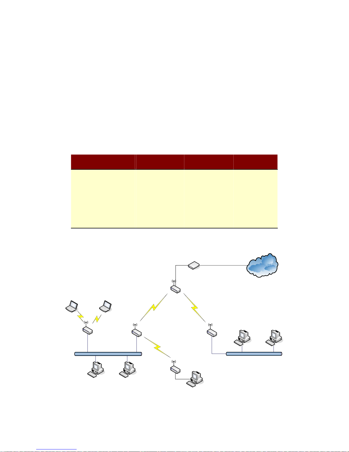
The following table shows the supporting combination of operation and
wireless radio modes.
Bridge Router WISP
AP
V V X
WDS
V V X
Client
V X V
AP+WDS
V V X
Hereafter are some topologies of network application for your reference.
Bridge Mode
With
AP
Bridge Mode
With
WDS + AP
Bridge Mode
Router Mode
With
WDS + AP
WISP Mode
Internet
Broadband
Modem
12
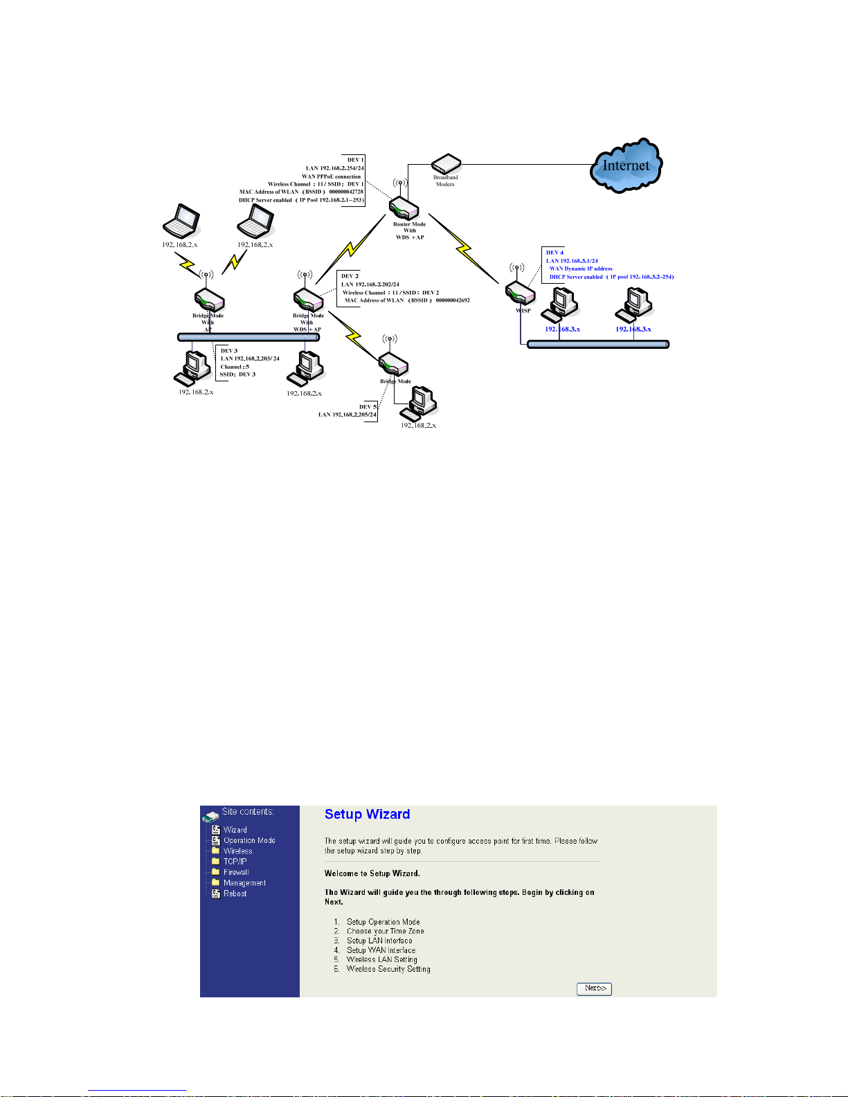
Examples of Configuration
This example demonstrates how to set up a network with different device
configurations. There are 2 DHCP servers (DEV1/DEV4) in the network to
control the IP configuration of 2 domains (192.168.2.x/192.168.3.x). Once
the setting is done, all the PCs can visit Internet through DEV1.
We assume all the devices keep the factory default setting. To make sure
that user can continuing press the rest button for more than 5 seconds to
restore the factory default setting.
The following descriptions show the steps to configure DEV1 to DEV5.
Configure DEV1:
1. Connect the ADSL modem to Ethernet port of device using Ethernet
cable.
2. Access the web server (http://192.168.2.254) of device from the
wireless station.
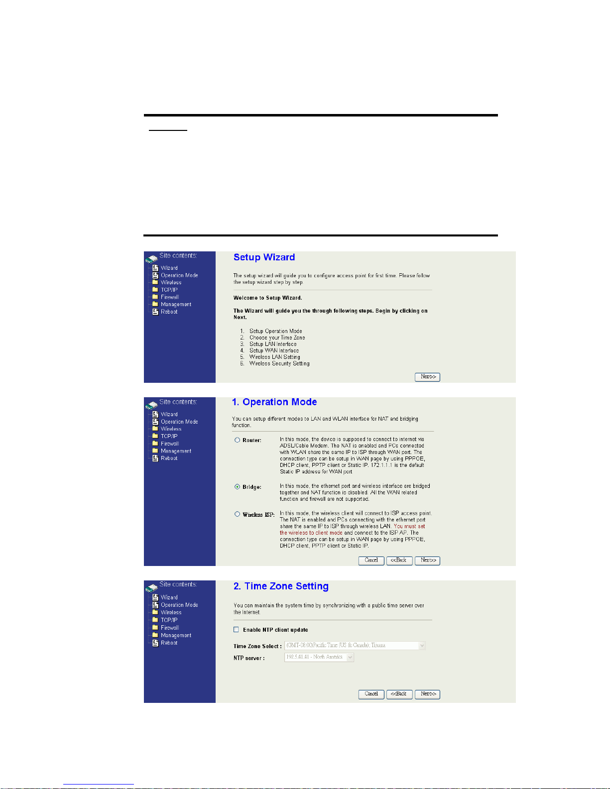
3. Use Wizard page to setup device.

13
4. Press “Next>>” button then set the “Operation Mode” to “Router” mode.
5. Press “Next>>” button then disable “Time Zone” function.
6. Press “Next>>” button then set the IP address of LAN interface.
7. Press “Next>>” button then select the “PPPoE” for “WAN Access Type”
and fill in the “User Name” and “Password” fields.
14
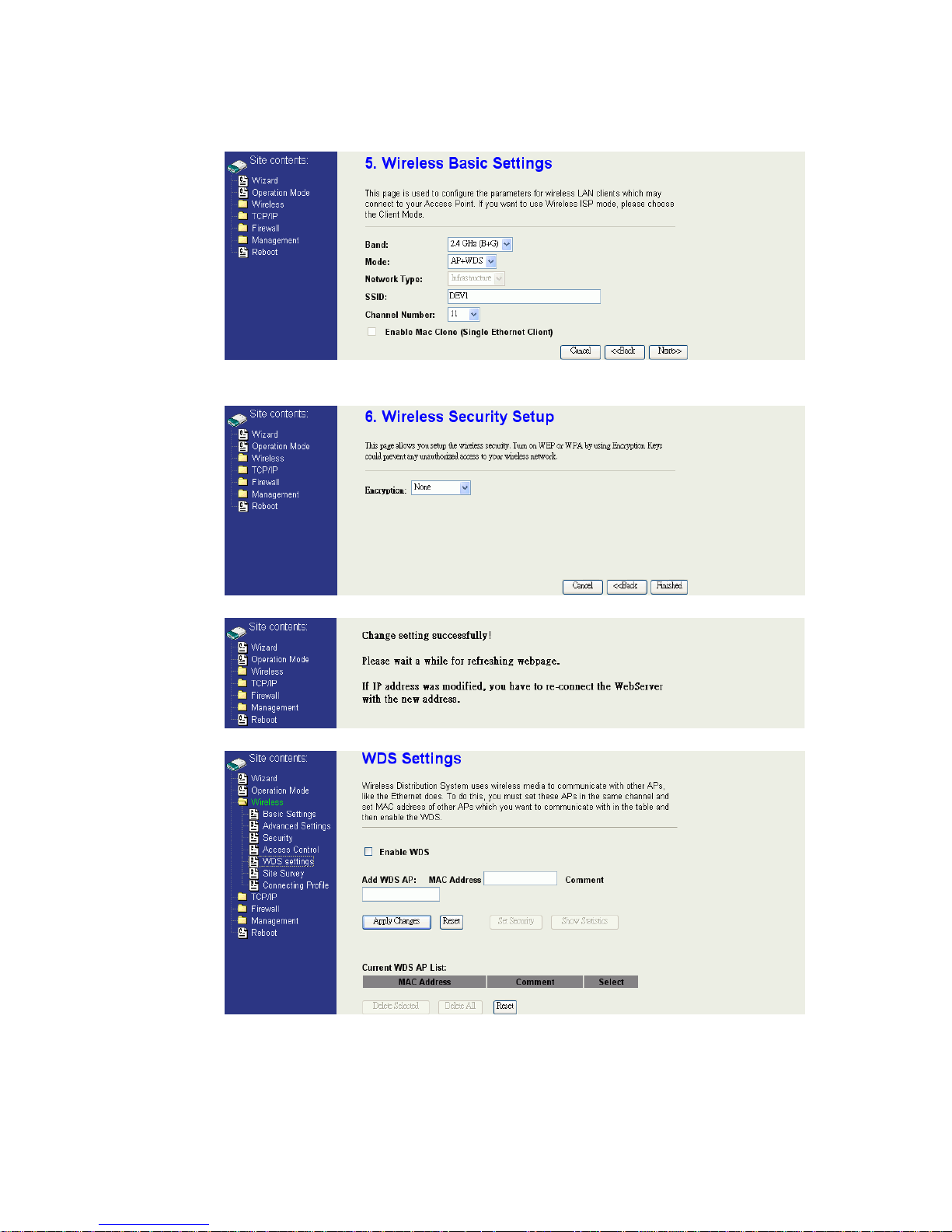
8. Press “Next>>” button then select the “AP+WDS” for “mode” and
change the SSID to “DEV1”.
9. Press “Next>>” button then select “None” for “Encryption” then press
“Finished” button.
10. Wait for refreshing web page.
11. Use “WDS Settings” page to configure WDS.
15
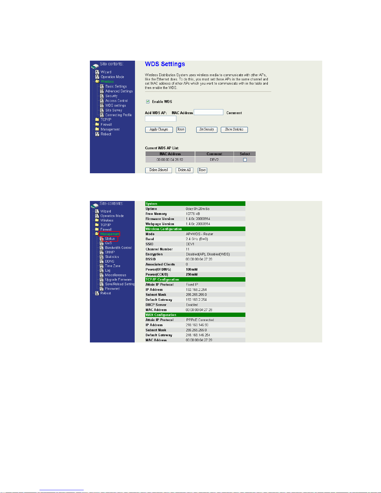
12. Enable WDS function and add the BSSID of DEV2 to “Current WDS AP
List”.
13. Since we access the device by wireless connection, it may temporarily
disconnect when applying the WDS setting. After re-connecting to the
device, use the “Status” page to check the settings.
16
Configure DEV2:
1. Access the web server (http://192.168.2.254) of device from the
Ethernet port.
Caution
If you configure multiple devices in the same PC, since the devices
have the same default IP address but different MAC addresses, it may
cause you not able to access the web server of device. If the situation
happens, please try to clean the ARP table of your PC by DOS
command “arp –d” then you can access the web server of device
using the default IP address.
2. Use Wizard page to setup device.
3. Press “Next>>” button then set the “Operation Mode” to “Bridge” mode.
4. Press “Next>>” button then disable “Time Zone” function.
17
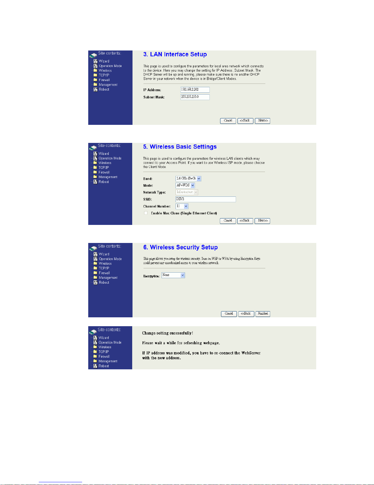
5. Press “Next>>” button then set the IP address of LAN interface.
6. Press “Next>>” button then select the “AP+WDS” for “mode” and
change the SSID to “DEV2”.
7. Press “Next>>” button then select “None” for “Encryption” then press
“Finished” button.
8. Wait for refreshing web page.
18
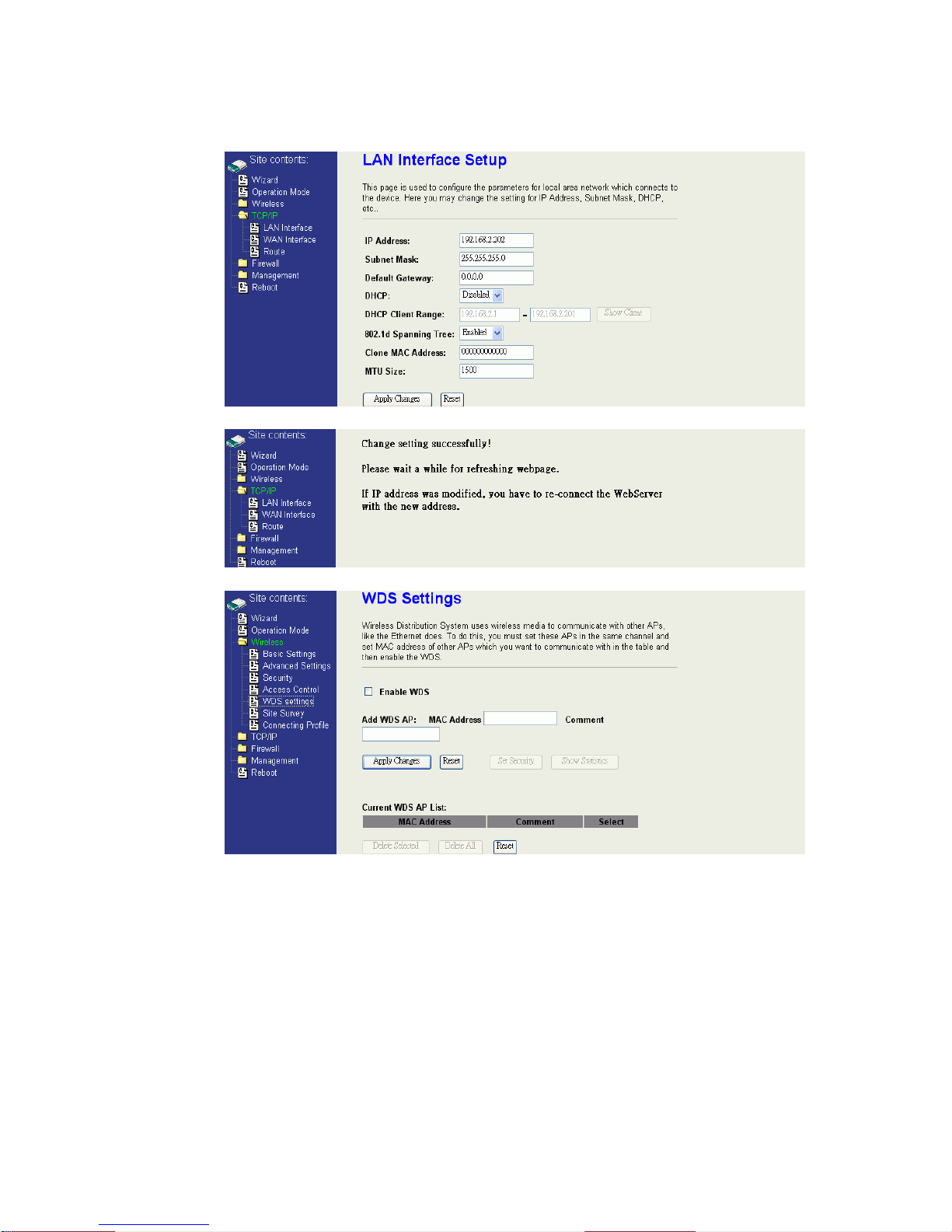
9. Access the web server by new IP address “192.168.2.202” then use
“LAN Interface” page to disable DHCP Server.
10. Wait for refreshing web page.
11. Use “WDS Settings” page to configure WDS.
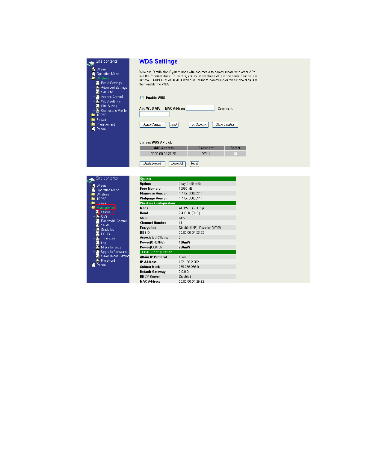
19
12. Enable WDS function and add the BSSID of DEV1 to “Current WDS AP
List”.
13. Use the “Status” page to check the settings.
20
Configure DEV3:
1. Access the web server (http://192.168.2.254) of device from the
Ethernet port.
Caution
If you configure multiple devices in the same PC, since the devices
have the same default IP address but different MAC addresses, it
may cause you not able to access the web server of device. If the
situation happens, please try to clean the ARP table of your PC by
DOS command “arp –d” then you can access the web server of
device using the default IP address.
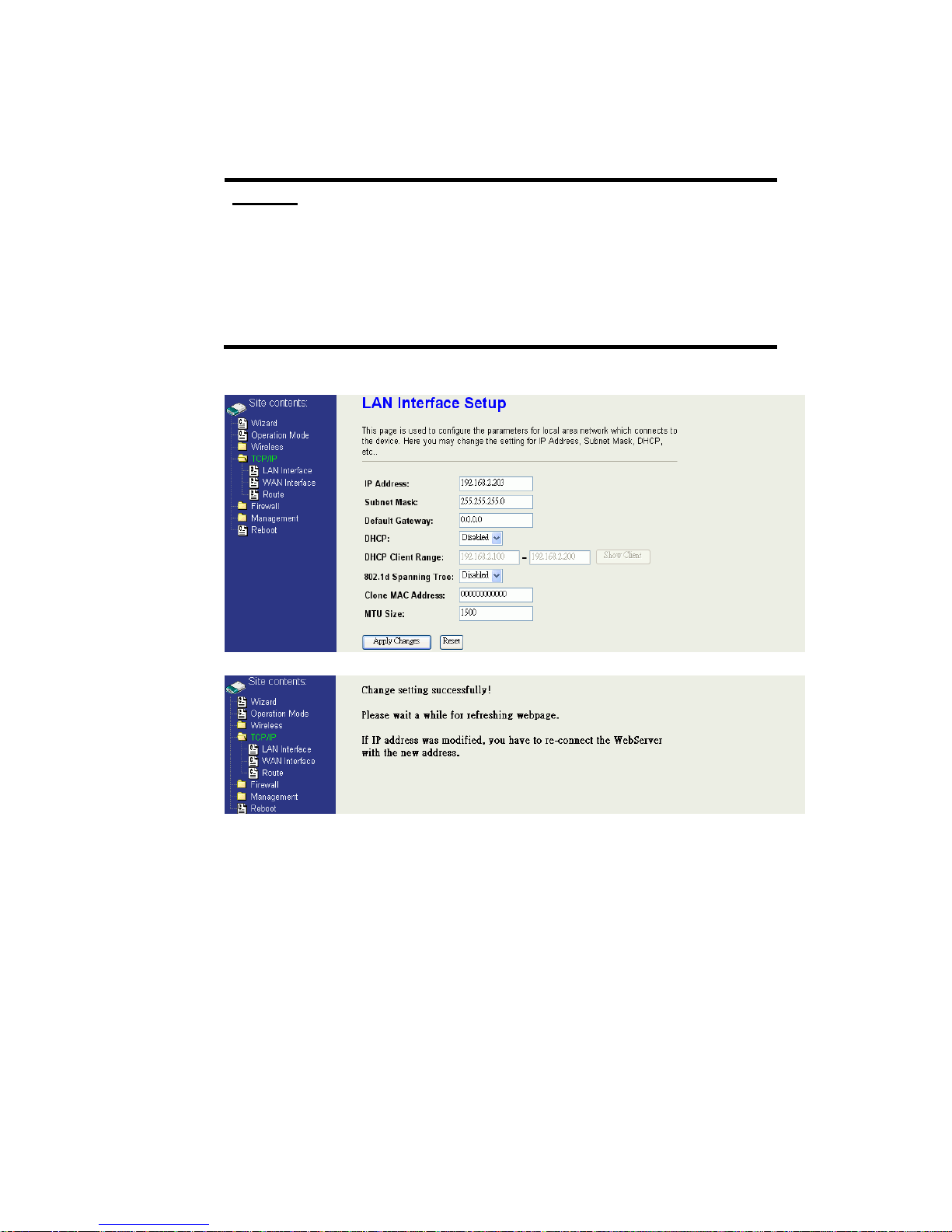
2. Use “LAN Interface” page to set the IP address of LAN interface and
disable DHCP server.
3. Wait for refreshing web page.

21
4. Access the web server by new IP address “192.168.2.203” then use
“Basic Settings” page to change SSID and CHANNEL.
5. Use the “Status” page to check the settings.
22
Configure DEV4:
1. Access the web server (http://192.168.2.254) of device from the
Ethernet port.
Caution
If you configure multiple devices in the same PC, since the devices
have the same default IP address but different MAC addresses, it
may cause you unable to access the web server of device. If the
situation happens, please try to clean the ARP table of your PC by
DOS command “arp –d” then you can access the web server of
device using the default IP address.
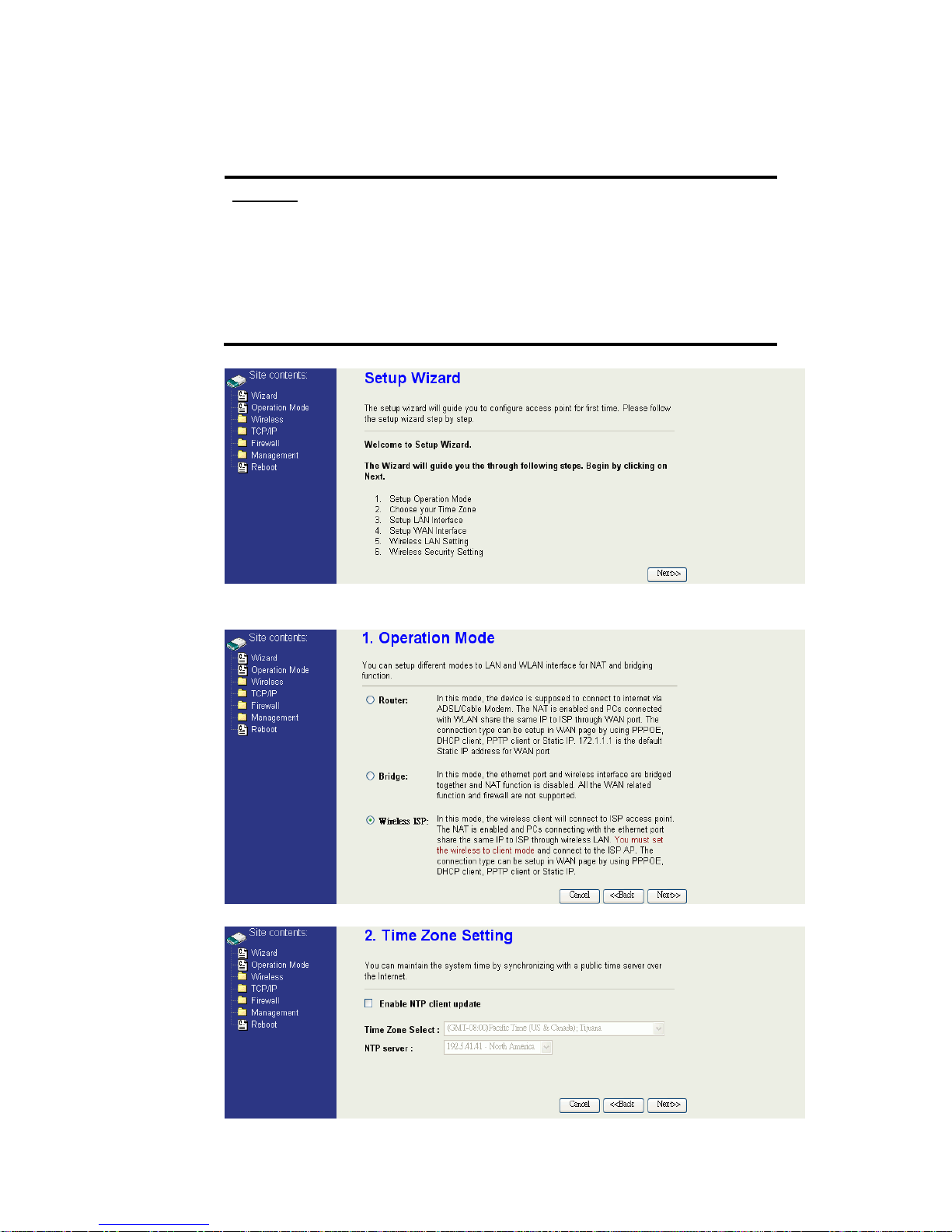
2. Use Wizard page to setup device.
3. Press “Next>>” button then set the “Operation Mode” to “Wireless ISP”
mode.
4. Press “Next>>” button then disable “Time Zone” function.
23
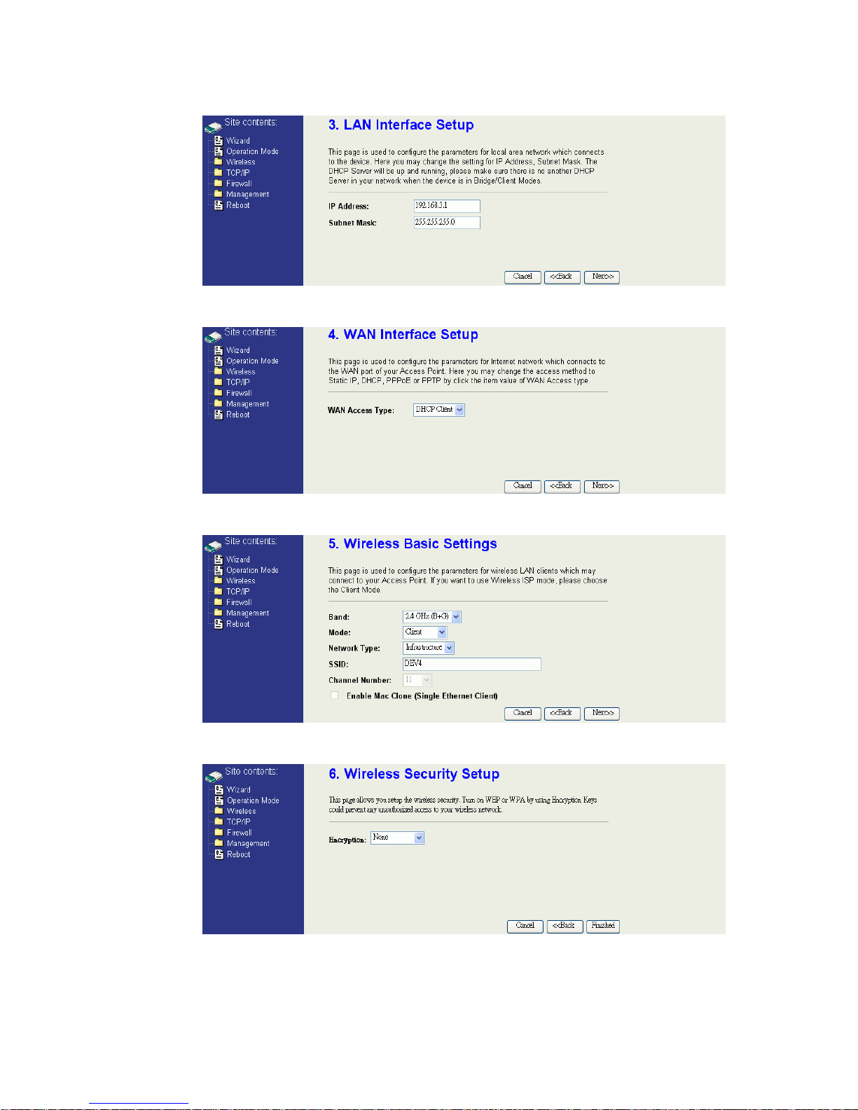
5. Press “Next>>” button then set the IP address of LAN interface.
6. Press “Next>>” button then select the “DHCP Client” for “WAN Access
Type”.
7. Press “Next>>” button then select the “Client” for “mode” and change
the SSID to “DEV4”.
8. Press “Next>>” button then select “None” for “Encryption” then press
“Finished” button.
24
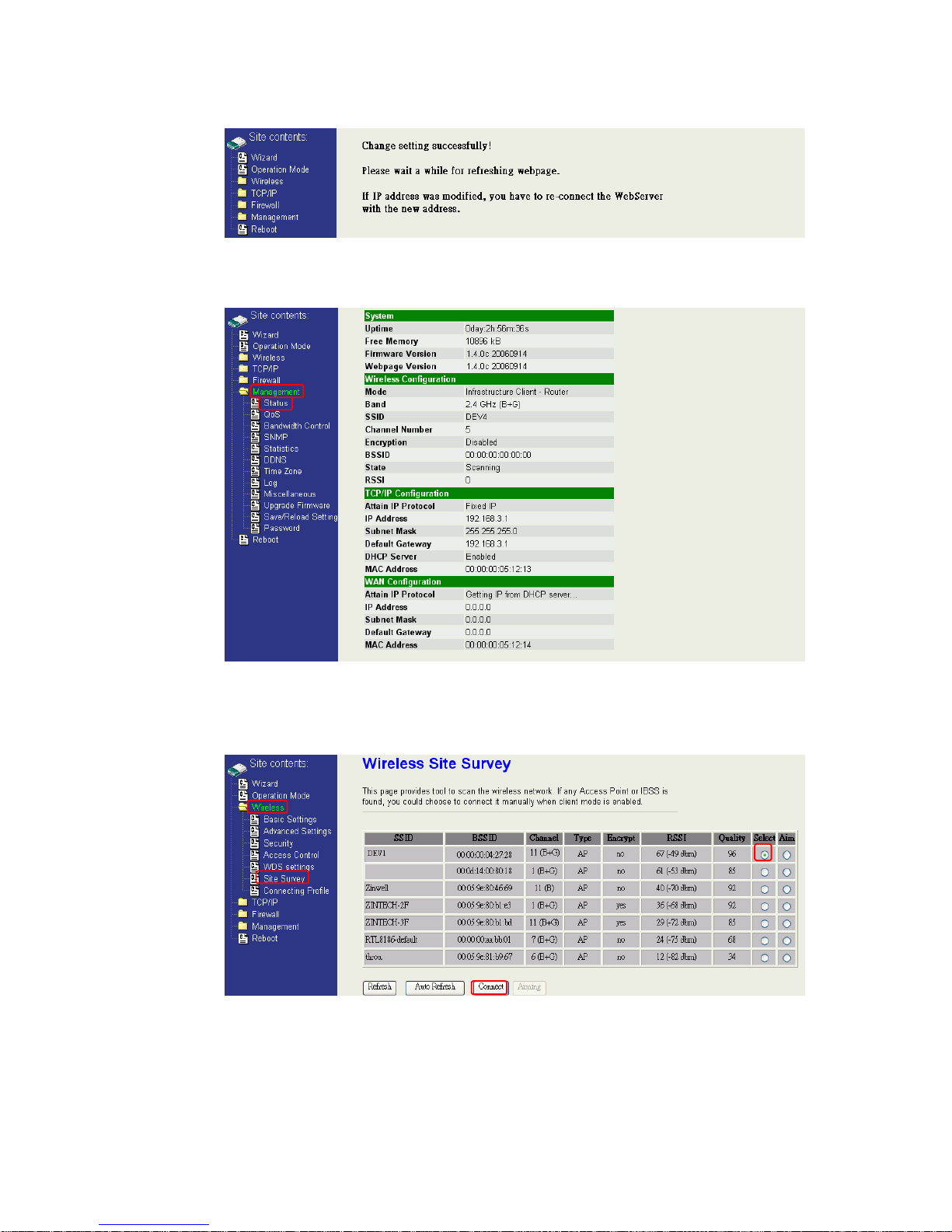
9. Wait for refreshing web page.
10. Change the IP address of your PC to 192.168.3.x then access the web
server by the new IP address “192.168.3.1” and use “Status” page
check the setting.
11. If the “State” of “Wireless Configuration” is not “Connected” or you want
to refresh the “RSSI “, please use “Site Survey” page to re-connect a
AP.

25
Configure DEV5:
1. Access the web server (http://192.168.2.254) of device from the
Ethernet port.
Caution
If you configure multiple devices in the same PC, since the devices
have the same default IP address but different MAC addresses, it
may cause you unable to access the web server of device. If the
situation happens, please try to clean the ARP table of your PC by
DOS command “arp –d” then you can access the web server of
device using the default IP address.
2. Use Wizard page to setup device.
3. Press “Next>>” button then set the “Operation Mode” to “Wireless ISP”
mode.
4. Press “Next>>” button then disable “Time Zone” function.
26
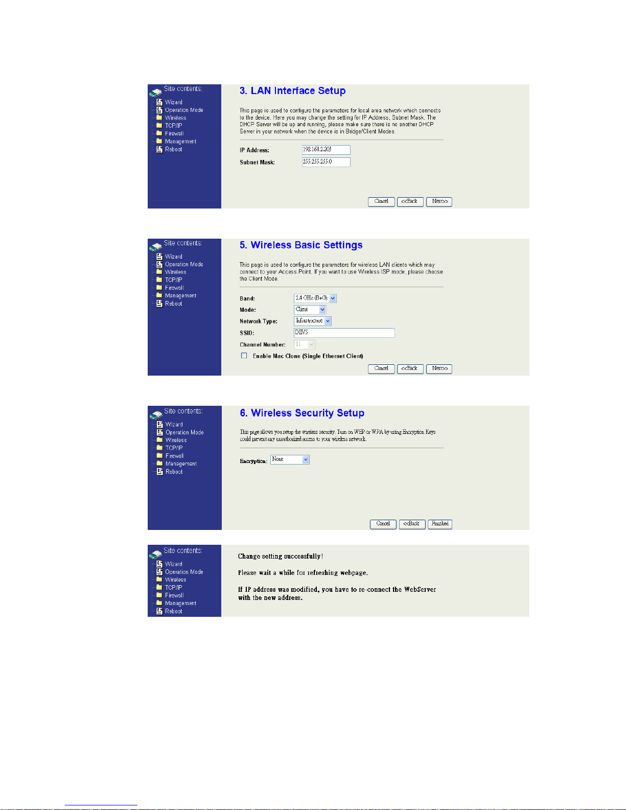
5. Press “Next>>” button then set the IP address of LAN interface.
6. Press “Next>>” button then select the “Client” for “mode” and change
the SSID to “DEV5”.
7. Press “Next>>” button then select “None” for “Encryption” then press
“Finished” button.
8. Wait for refreshing web page.
 Loading...