

Page 1
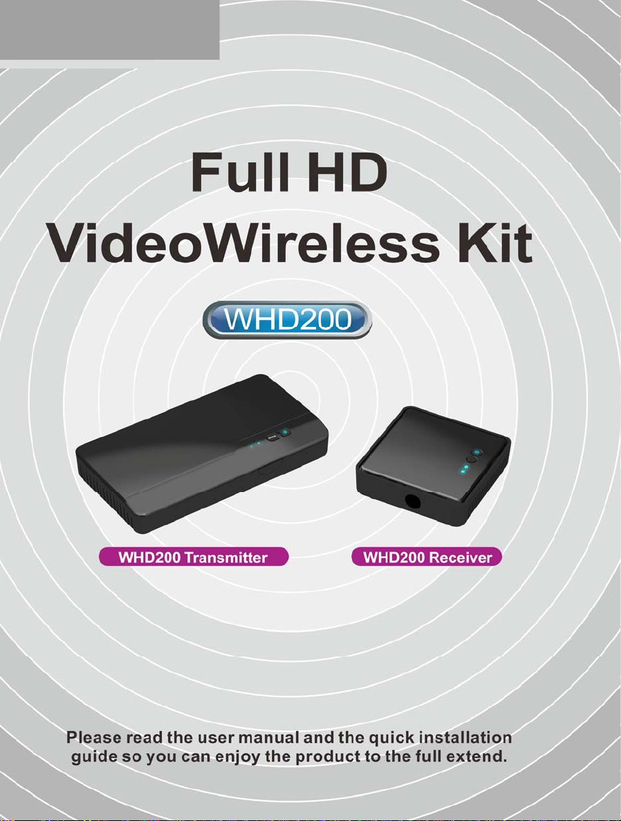
0
Page 2

Table of Contents
TABLE OF CONTENTS ............................................................................................................0
1. IMPORTANT INFORMATION
SAFETY PRECAUTIONS ...........................................................................................................2
DANGER: BE CAREFUL WITH ELECTRICITY.............................................................................2
2. INTRODUCTION
2.1 PACKING CONTENT ........................................................................................................7
2.2 OVERVIEW......................................................................................................................7
2.2 OVERVIEW......................................................................................................................3
2.2.1 TRANSMITTER (TX): PC TO TV TRANSMITTER.............................................................. 3
2.2.2 RECEIVER (RX): PC TO TV RECEIVER ............................................................................3
2.2.2 RECEIVER (RX): PC TO TV RECEIVER ............................................................................8
2.2.3 REMOTE CONTROLLER UNIT (RCU) INSTRUCTION .............................................................9
3. INSTALLATION ................................................................................................................10
STEP1: SETUP THE TRANSMITTER TRANSMITTER............................................................. 10
STEP2: SETUP THE RECEIVER RECEIVER............................................................................. 11
STEP3: SETUP THE IR BLASTER EXTENDER CABLE AND IR SENSOR EXTENDER CABLE ..... 12
STEP 4: BOOT UP THE TRANSMITTER AND RECEIVER .......................................................13
STEP 5: MOUNTING THE WHDI DEVICE TO THE WALL ................................................... 18
................................................................................................................7
............................................................................................2
4. TROUBLESHOOTING....................................................................................................... 19
5. SUPPORTED RESOLUTION..............................................................................................21
6. AUDIO BIT RATE SUPPORT.............................................................................................22
7. PRODUCT SPECIFICATION ..............................................................................................22
1
Page 3
1. Important Information
Please take the time to read this user manual
before using the TRANSMITTER and RECEIVER.
It contains important information about
operating your Full HD video wireless kit.
Our limited warranty applies when the product
is handled properly for intended use, in
accordance with its operating instruction.
However, the warranty may be void in the
following cases:
Repair, product modification or alteration
have been performed by unauthorized
service personnel
Damages caused by accidents, including
but not limited to, lightning, water, fire,
or moisture
Use of an AC adapter not compatible with
the product and its voltage rating
The model number on the product has
been altered, deleted, removed or made
illegible.
Safety Precautions
TO REDUCE THE RISK OF ELECTRICAL SHOCK
NO USER-SERVICEABLE PARTS ARE INSIDE
REFER SERVICING TO QUALIFIED
WARNIN G!
RISK OF
ELECTRICAL
SHOCK
DO NOT OPEN
WARMI NG:
DO NOT REMOVE THE COVER
PERSONNEL
Danger: Be careful with electricity.
Power to the units must be switched off
before any work is undertaken, such as
any AV device connection or TV
connection.
Power outlet: To prevent electric shock,
make sure to use the appropriate AC
adapters as power supply to the
transmitter and the receiver.
Power cord: Be sure the power cord is
routed so that it will not be stepped on or
pinched by heavy items.
Power overloading: Avoid overloading
electrical outlets or extension cords
which otherwise could result in electric
shock or fire.
Lightning: Disconnect the product from
the power source if it is left unattended
for a long period of time, and to protect
the product from lightning.
Always disconnect the power cord from
the power outlet when you are not using
your Full HD Video wireless kit. This
reduces the risk of electric shocks or fire.
Warning
This product should not be exposed to
dripping or splashing. No object filled
with liquids, such as vases, should be
placed on the product.
Object Entry: To avoid electric shock,
never stick anything in the slots on the
case or remove the cover.
Place receiver/transmitter on a flat, hard
and stable surface
Ven tilat ion: Do not block the ventilation
slots on the receiver/transmitter or place
any heavy object on the top cover.
Blocking the air flow could damage the
receiver. Arrange components so that air
can flow freely around the receiver.
Ensure that there is adequate ventilation
if the receiver is placed in a stand.
Put the receiver/transmitter in a property
ventilated area, away from direct sunlight
or any source of heat.
2
Page 4
Water Exposure: To reduce the risk of fire
or electric shock, do not expose the
receiver/transmitter to rain or moisture.
This is indoor solution.
Our company has the right to modify
this document without any notice.
DECLARATION OF CONFORMITY
This device complies with Part 15 of the FCC
Rules. Operation is subject to the following
two conditions:
(1) This device may not cause harmful
interference, and
(2) This device must accept any interference
received, including interference that may
cause undesired operation.
This Class B digital apparatus complies
Canadiàn ICES-003. Cet appareil numérique
do la class B est conforme à la norme
NMB-003 DU Canada.
EMI (Electro Magnetic Interference) tested.
EN55032
Electrowagnetic compatibility of multimedia
equipment-Emission requirements
EN 55022 Information technology
equipment----
Radio disturbance characteristics--- Limits
and methods of measurement
EN 61000-3-2 Electromagnetic compatibility
(EMC)---
Part 3-2:Limits---Limits for harmonic current
emissions (equipment input current up to
and including 16 A per phase)
EN 61000-3-3 Electromagnetic compatibility
(EMC)---
Part 3:Limits---Section 3: Limitation of
voltage changes, voltage fluctuations and
flicker in public low-voltage supply systems,
for equipment with rated current ≦16 A per
phase and not subject to conditional
connection
EN 55024 Information technology
equipment----
Immunity characteristics---Limits and
methods of measurement
EN 60065 Audio,video and similar
electronic apparatus—Safety requirements
TRADEMARK INFORMATION
HDMI, the HDMI Logo and
High-Definition Multimedia Interface
are trademarks of HDMI Licensing LLC.
Special Notice
Never use this product nearby an aircraft
or medical facility. It can cause
interference or undesirable effect on the
operation result.
Use of this product in the following
locations may result in abnormal video
and audio output (noise, blocked image...
etc,).
Product installed in the walls made
of concrete.
Product is situated near the
refrigerator or metal fitment.
A cluttered room where the
This product has been tested and
WHDI DEVICE may interfere 5GHz
Optimal range between WHDI DEVICE
wireless signals may be blocked
manufactured to comply with each
country’s safety rules. However, there is
no guarantee that interference will not
occur in some installation scenario. If the
interference happens, increase the
distance between the transmitter and
receiver.
wireless devices, such as routers or other
wireless devices. Therefore, if you have
an 802.11n router, configure it to the 2.4
GHz band rather than the 5GHz band.
transmitter and receiver is between 2
and 20 meters within line of sight.
Europe – EU Declaration of
Conformity
This device complies with the essential
requirements of the R&TTE
Directive2014/53/EU. The following test
methods have been applied in order to
prove presumption of conformity with
the essential requirements of the R&TTE
Directive 2014/53/EU:
3
Page 5

EN 60065: 2014/AC:2016
Audio, Video and Similar electronic
apparatus
WHD100
EN 62479:2010
Assessments of the compliance of
Low-power electronic and elect cal
equipment with the basic restrictions
related to human exposure to
electromagnetic fields (10MHz to
300GHz).
EN 50385:2002
Product standard to demonstrate the
compliances of radio base stations and
fixed terminal stations for wireless
telecommunication systems with the
basic restrictions or the reference levels
related to human exposure to radio
frequency electromagnetic fields
(110MHz - 40GHz). General public
EN 301 893 V1.8.1: 2015
Broadband Radio Access Networks
(BRAN); 5 GHz high performance RLAN;
Harmonized EN covering essential
requirements of article 3.2 of the R&TTE
Directive
EN 301 489-1 V1.9.2: 2011
Electromagnetic compatibility and Radio
Spectrum Matters (ERM); Electro
Magnetic Compatibility (EMC) standard
for radio equipment and services; Part 1:
Common technical requirements
EN 301 489-17 V2.2.1 2012
Electromagnetic compatibility and Radio
spectrum Matters (ERM); Electro
Magnetic Compatibility (EMC) standard
for radio equipment
Part 17: Specific conditions for
Broadband Data transmission systems
Hereby, Zinwell declares that this Full HD
Video wireless kit is in compliance with the
essential requirements and other relevant
provisions of Directive2014/53/EU
Federal Communication
Commission Interference
Statement
This device complies with Part 15 of
the FCC Rules. Operation is subject to
the following two conditions: (1) This
device may not cause harmful
interference, and (2) this device must
accept any interference received,
including interference that may cause
undesired operation.
This equipment has been tested and
found to comply with the limits for a
Class B digital device, pursuant to Part
15 of the FCC Rules. These limits are
designed to provide reasonable
protection against harmful
interference in a residential
installation.
This equipment generates, uses and
can radiate radio frequency energy
and, if not installed and used in
accordance with the instructions, may
cause harmful interference to radio
communications.
However, there is no guarantee that
interference will not occur in a
particular installation.
If this equipment does cause harmful
interference to radio or television
reception, which can be determined
by turning the equipment off and on,
the user is encouraged to try to
correct the interference by one of the
following measures:
4
Page 6
Reorient or relocate the receiving
antenna.
Increase the separation between the
equipment and receiver.
Connect the equipment into an outlet on
a circuit different from that to which the
receiver is connected.
Consult the dealer or an experienced
radio/TV technician for help.
FCC Caution: Any changes or
modifications not expressly approved by
the party responsible for compliance
could void the user's authority to operate
this equipment.
This transmitter must not be co-located
or operating in conjunction with any
other antenna or transmitter.
Radiation Exposure Statement
(Transmitter):
This equipment complies with FCC
radiation exposure limits set forth for
an uncontrolled environment. This
equipment should be installed and
operated with minimum distance 20cm
between the radiator & your body.
Radiation Exposure Statement
(Receiver):
This equipment complies with FCC
radiation exposure limits set forth for
an uncontrolled environment. This
equipment should be installed and
operated with minimum distance 20cm
between the radiator & your body.
Note: The country code selection is for
non-US model only and is not available
to all US model. Per FCC regulation, all
WiFi product marketed in US must fixed
to US operation channels on
IndustryCanadastatement:
ThisdevicecomplieswithISEDʼs
licence-exempt Ross. Operation is
subject to the following two conditions:
(1) This device may not cause harmful
interference, and (2) this device must
accept any interference received,
including interference that may cause
undesired operation.
Le présent appareil est conforme aux
CNR d’ ISED applicables aux appareils
radio exempts de licence. L’exploitation
est autorisée aux deux conditions
suivantes : (1) le dispositif ne doit pas
produire de brouillage préjudiciable, et
(2) ce dispositif doit accepter tout
brouillage reçu, y compris un
brouillage susceptible de provoquer un
fonctionnement indésirable.
Caution:
(i) the device for operation in the
band 5150-5250 MHz is only for
indoor use to reduce the potential for
harmful interference to co-channel
mobile satellite systems;
(ii) the maximum antenna gain
permitted for devices in the bands
5250-5350 MHz and 5470-5725 MHz
shall be such that the equipment still
complies with the e.i.r.p. limit;(iii) the
maximum antenna gain
permitted for devices in the band
5725-5850 MHz shall be such that the
equipment still complies with the
e.i.r.p. limits pecifiedforpoint-to-point
and non-point-to-point operation as
appropriate; and
5
Page 7

(iv) Users should also be advised that
high-power radars are allocated as
primary users (i.e. priority users) of
the bands 5250-5350 MHz and
5650-5850 MHz and that these
radars could cause interference
and/or damage to LE-LAN devices.
Avertissement:
Le guide d’utilisation des dispositifs
pour réseaux locaux doit inclure des
instructions précises sur les restrictions
susmentionnées, notamment :
(i) les dispositifs fonctionnant dans la
bande 5150-5250 MHz sont réservés
uniquement pour une utilisation à
l’intérieur afin de réduire les risques de
brouillage préjudiciable aux systèmes
de satellites mobiles utilisant les mêmes
canaux;
(ii) le gain maximal d'antenne permis
pour les dispositifs utilisant les bandes
de 5250 à 5350 MHz et de 5470 à 5725
MHz doit être conforme à la limite de la
p.i.r.e;
(iii) le gain maximal d'antenne permis
(pour les dispositifs utilisant la bande de
5725 à 5850 MHz) doit être conforme à
la limite de la p.i.r.e. spécifiée pour
l'exploitation point à point et
l’exploitation non point à point, selon le
cas;
(iv) De plus, les utilisateurs devraient
aussi être avisés que les utilisateurs de
radars de haute puissance sont désignés
utilisateurs principaux (c.-à-d., qu’ils ont
la priorité) pour les bandes 5250-5350
MHz et 5650-5850 MHz et que ces
radars pourraient causer du brouillage
et/ou des dommages aux dispositifs
LAN-EL.
Radiation Exposure Statement:
This equipment complies with ISED
radiation exposure limits set forth for an
uncontrolled environment. This
equipment should be installed and
operated with minimum distance 20cm
between the radiator & your body.
Déclaration d'exposition aux
radiations:
Cet équipement est conforme aux
limites d'exposition aux rayonnements
ISED établies pour un environnement
non contrôlé. Cet équipement doit être
installé et utilisé avec un minimum de
20 cm de distance entre la source de
rayonnement et votre corps.
6
Page 8
Adapter
r
2. Introduction
WHDI DEVICE is a Full HD wireless transmission device.
This solution delivers uncompressed 1080p full HD video and audio content to your existing HDTV
set wirelessly. It operates the transmission in 4.9 GHz~ 5.9 GHz frequencies and it can adjust its
communication frequency automatically in case of interference from another RF system. With
built-in Omni-directional antennas, it can transmit uncompressed video content to 20 meters (66
feet) LOS (Line of sight) with no latency.
Both IR Sensor Extender Cable and IR Blaster Extender Cable are included in the package so users
can point their remote control of the AV source at the receiver directly for device operation.
2.1 Packing Content
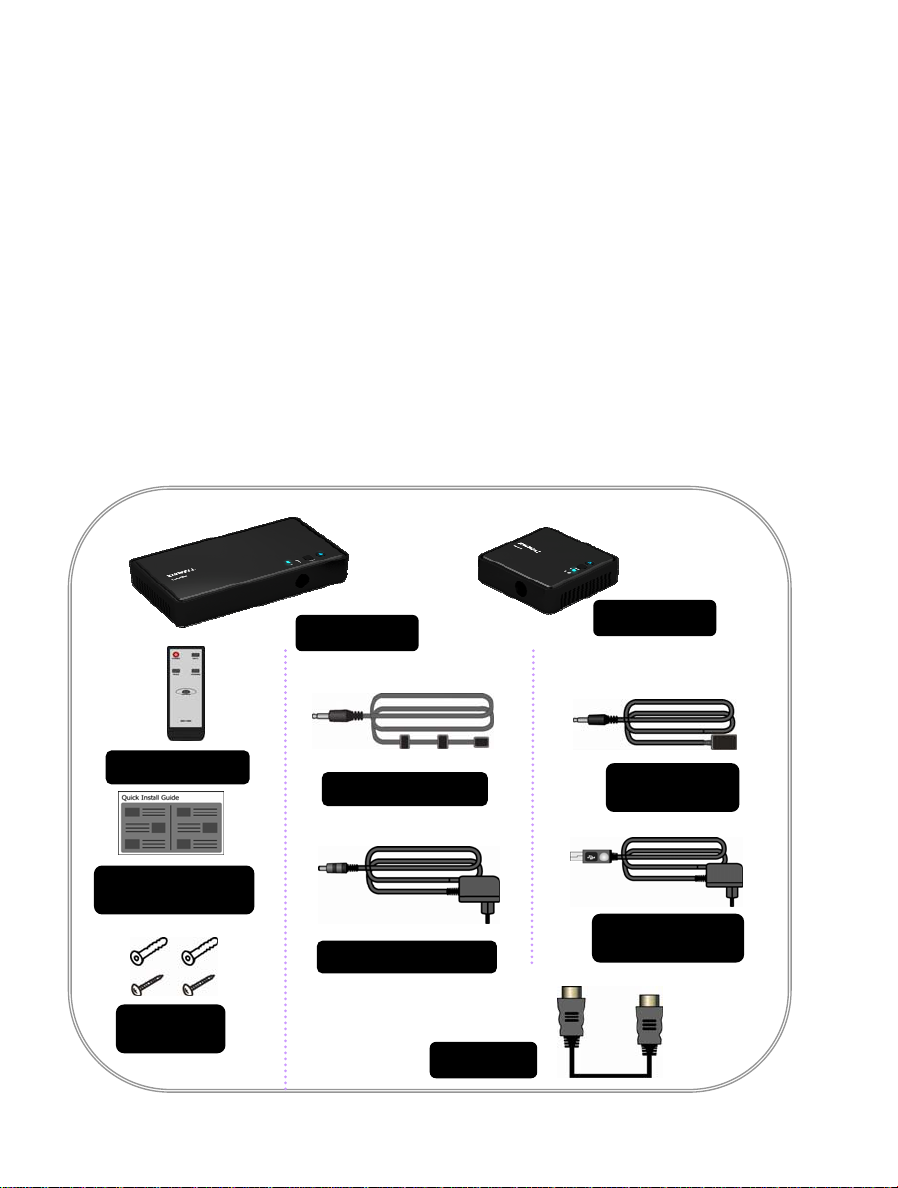
Please check whether the following items are present in the package. If any items missed or
damaged, please call your dealer.
TRANSMIT
RECEIVER
Remote Control
IR Blaster cable
Quick Installation
Guide
DC Power Adapter
Anchors x2
Screws x2
HDMI cable
IR Sensor
cable
extende
Mini USB Power
7
Page 9
2.2 Overview
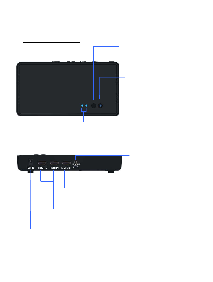
2.2.1 TRANSMITTER (TX): PC to TV Transmitter
Front Panel Buttons and LEDs
Main Unit Back Panel
HDMI OUT
Connect Transmitter to High-definition audio/video devices
that have an HDMI port using a provided HDMI cable.
HDMI OUT
Connect to HDTV set via an HDMI cable.
Source LEDs
These two LED indicators are lit insolid blue to show
current input you switch.
Source Selection Button
Press to switch Source inputs of
the transmitter.
Power Button with LED
Indicator
Press to turn the transmitter on
and off. The indicator in the
power button is lit in solid blue
when the power is on, and turns
red in standby mode.
IR OUT Blaster Extender
Jack
Plug the IR Blaster Extender
Cable into the IR OUT jack of
DC IN
For connecting the SWW1810T power adapter.
3
Page 10
2.2.2 RECEIVER (RX): PC to TV Receiver
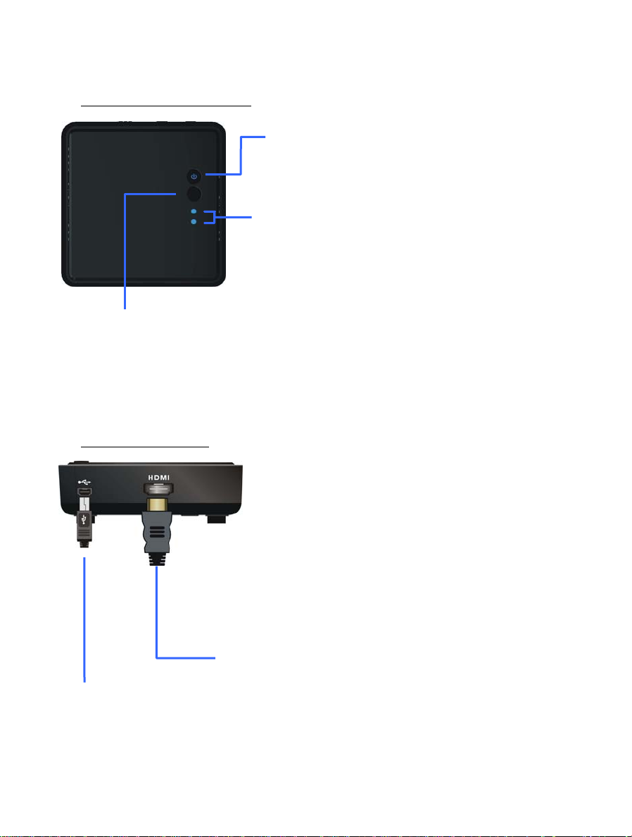
Front Panel Buttons and LEDs
Main Unit Back Panel
DC IN
Connect to receiver’s
power adapter.
Source Button
Press this button for Source
input selection.
Source LEDs
For HDMI1 and HDMI2
selected indication.
HDMI OUT
Connect to HDTV set via an HDMI cable.
Power Button with LED indicator
Press to turn the receiver on and off. The indicator in
the power button lights up in blue when the power is
on, and turns red in standby mode.
8
Page 11
2.2.3 Remote Controller Unit (RCU) Instruction
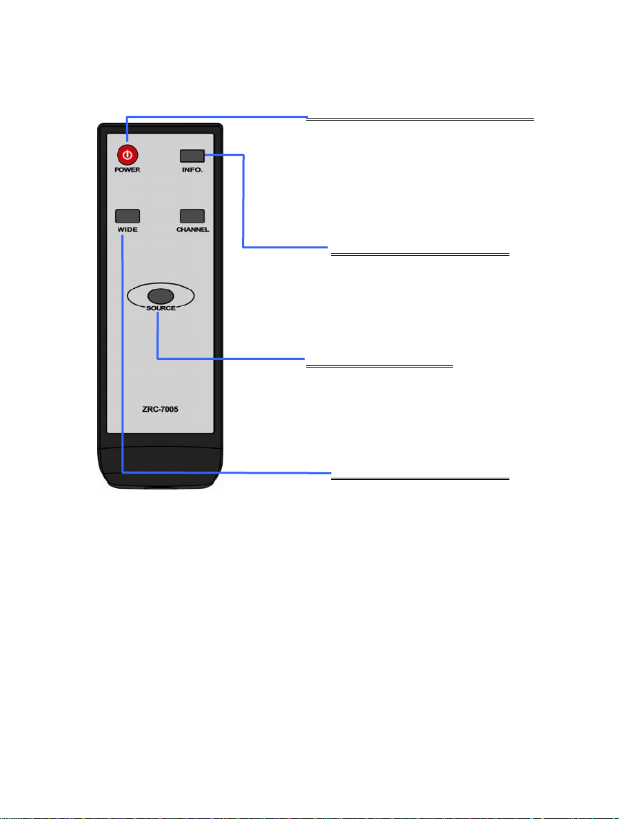
POWER Button
Press to turn the Transmitter & Receiver
on/off.
When both of TX & RX Power LEDs are red,
press Power button either TX OR RX, it can
wake up each other automatically.
INFO. Button
Press this button to display OSD for
system related information on
HDTV connected on receiver.
SOURCE Button
Press to switch the audio/video
sources input connected to
transmitter directly.
IR Button
Press to switch the IR Blaster
frequency to meet Source device’s
requirement. It can switch IR
Blaster frequency 47K to 56K to
36K recurring.
9
Page 12
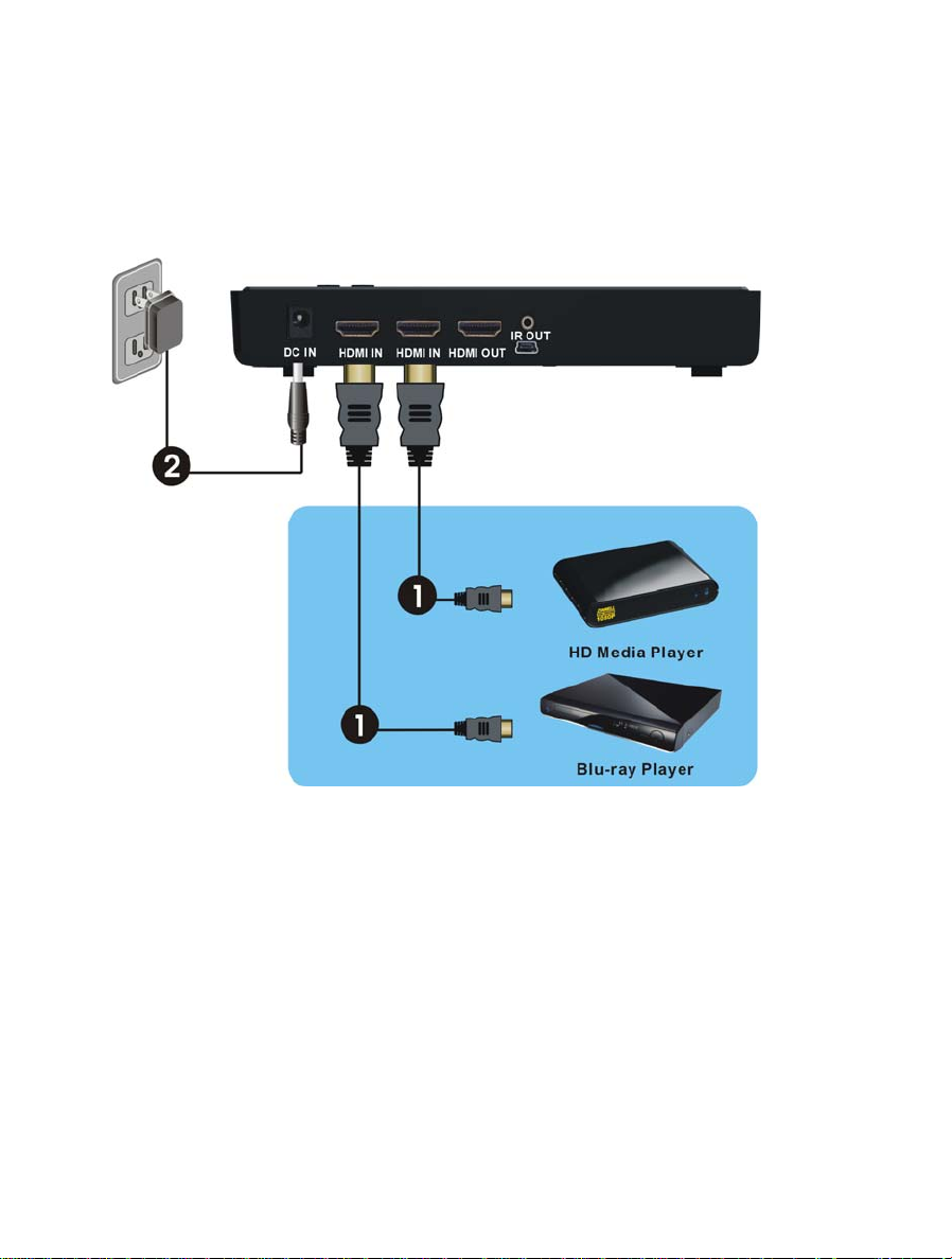
3. Installation
Step1: Setup the TRANSMITTER transmitter
Connect Two High-Definition Audio/Video Sources to the transmitter:
(1) Connect the transmitter’s “HDMI IN” to the High-Definition AV sources’ “HDMI OUT” through
by HDMI cable. The transmitter has two HDMI inputs for the High-Definition source device, like
PS3, Blu-ray Player.
(2) Connect the transmitter’s “HDMI OUT” to the HDTV set’s “HDMI IN” port with an HDMI cable
for the loop-through connection.
(3) Connect the supplied power adapter to the DC IN jack of the transmitter and a wall socket. The
LED indicator in the POWER button lights up in blue when the TRANSMITTER is connected to
the power mains.
10
Page 13
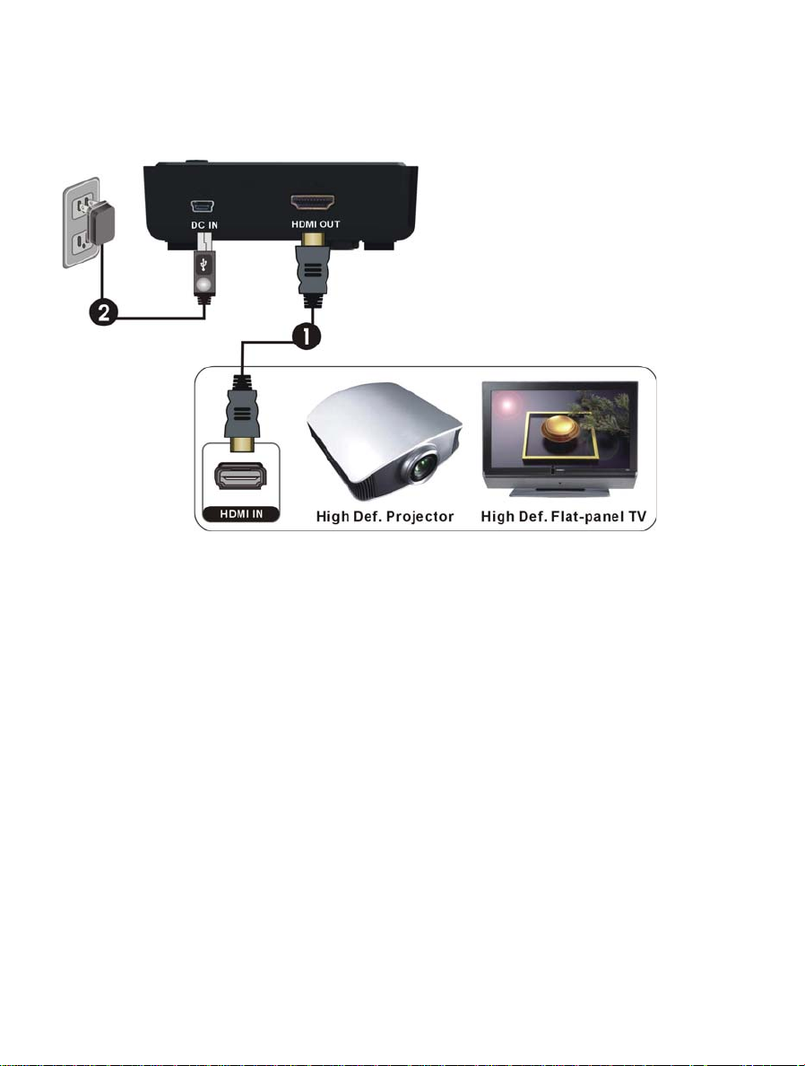
Step2: Setup the RECEIVER receiver
HDTV set Connection with RECEIVER:
(1) Connect the HDMI cable to the HDMI OUT jack of the receiver and to your HDTV set
(or an HD projector).
Press the Source / Input button of your TV’s remote to select the appropriate “HDMI”
video input.
(2) Connect the supplied power adapter to the DC IN jack of the receiver and a wall
socket. The POWER LED indicator lights up in blue when the receiver is connected to
the power mains.
11
Page 14
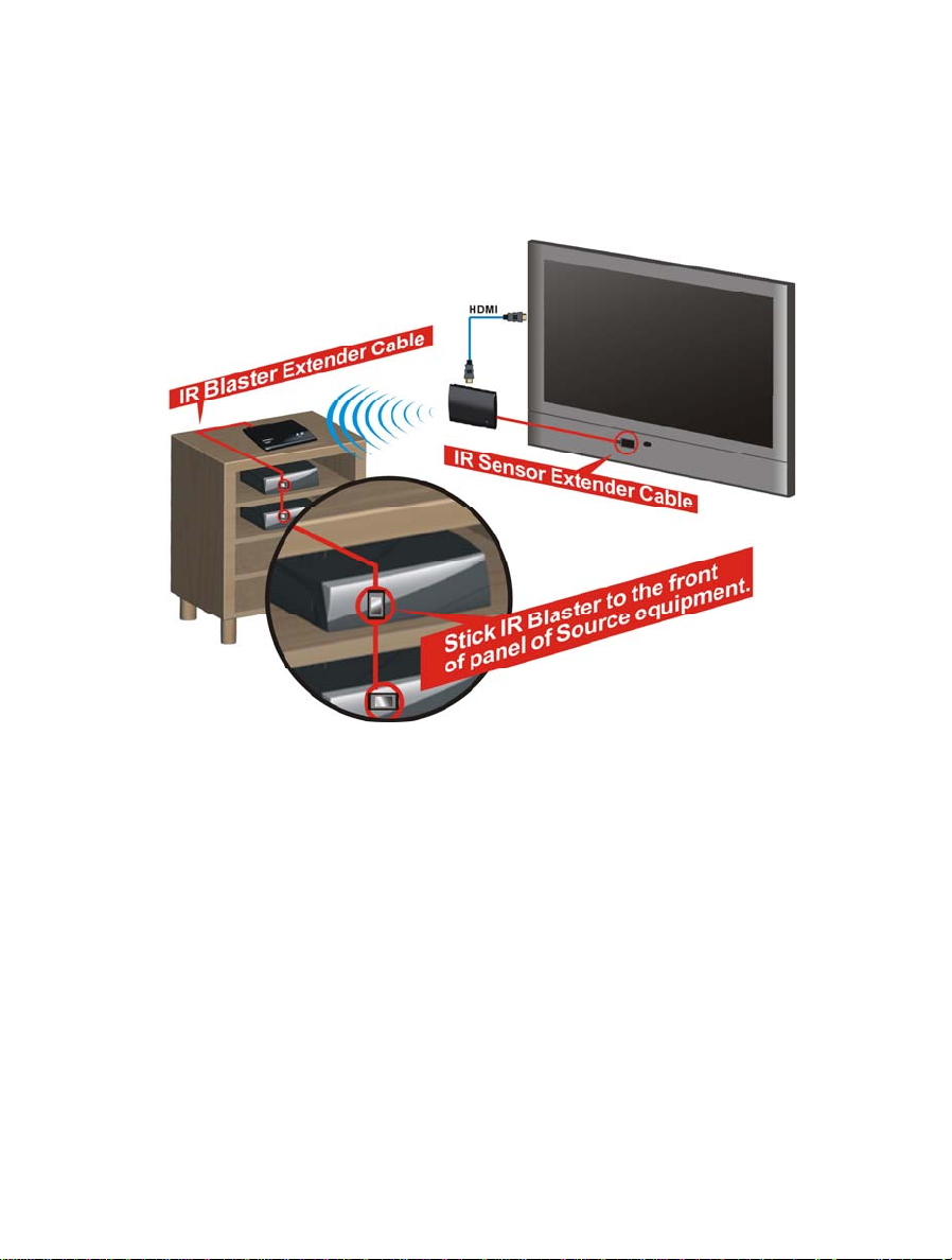
Step3: Setup the IR blaster extender cable and IR sensor extender cable
If necessary, connect the Infrared (IR) blaster (or sensor) Extender cable. Users can point
hand-held remote control of your High Definition AV equipment at the receiver or the HDTV set
to operate the source devices, not exceeding the distance of 66 feet at Line-of-sight.
(1) Plug the IR blaster cable into the IR OUT jack of the transmitter.
(2) Please try to manually move the IR blaster in the front of the front panel of your HD device
and then press the key of remote control to search a good position of IR response. Paste the
IR blaster head near the front of IR sensor of your High-Definition audio/video devices.
(3) When the IR blaster cable is connected, it relays infrared command from your remote control
to the device. Users can control their AV devices by pointing their remote control to the
receiver instead of to their AV equipment.
(4) If the receiver will be out of the direct line of sight of your remote controls, plug the IR Sensor
Extender cable into the IR IN jack of the receiver and place the IR sensor on the front of TV
for operation.
Note:
(1) The IR sensor supports 36KHz ~ 56KHz (NEC, RC5, RC6) remote’s signal protocol. Therefore, it is
possible that some devices may not be supported.
(2) The IR blaster supports 47KHz remote’ signal protocol.
12
Page 15
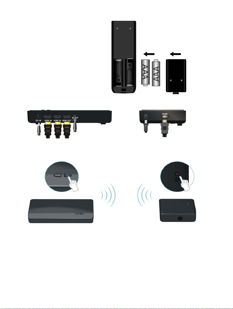
Step 4: Boot up the Transmitter and
Receiver
(1) Place the two AAA batteries into the
remote control.
(2) After the power cord is plugged into the electrical outlet, the WHDI DEVICE will be turned on
automatically.
(3) If it is in Standby mode (Both POWER LED of transmitter and receiver are lit in red), press the
POWER button on both transmitter and receiver to turn on the transmitter and the receiver.
(4) If transmitter’s HDMI out display is on (Transmitter POWER LED is lit in purple) and receiver
stay in Standby mode (Receiver POWER LED is lit in red), press the POWER button of receiver
ONLY to wake up and make connection between transmitter and the receiver for enable display
out on receiver side.
Note: User can press POWER button of transmitter to turn off both transmitter & receiver
simultaneously any time.
13
Page 16
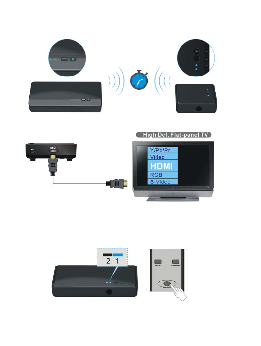
(5) During the warm-up, the POWER LED will blink in blue until the signal link between the
TRANSMITTER and the RECEIVER is established. It will take 15 ~ 20 seconds for system boot up
successfully.
(6) Ensure your TV set or projector is in “HDMI input” mode, and is already powered on.
(7) Press the Source button on the RCU or on the top of receiver / transmitter for Source input
switch until you see the video being broadcasted from your device.
(8) If all operation is normal, the POWER LED and INFO./CHANNEL LED will glow in solid blue.
Please refer to the below form containing detailed LED indicator and OSD description of
transmitter / receiver:
14
Page 17
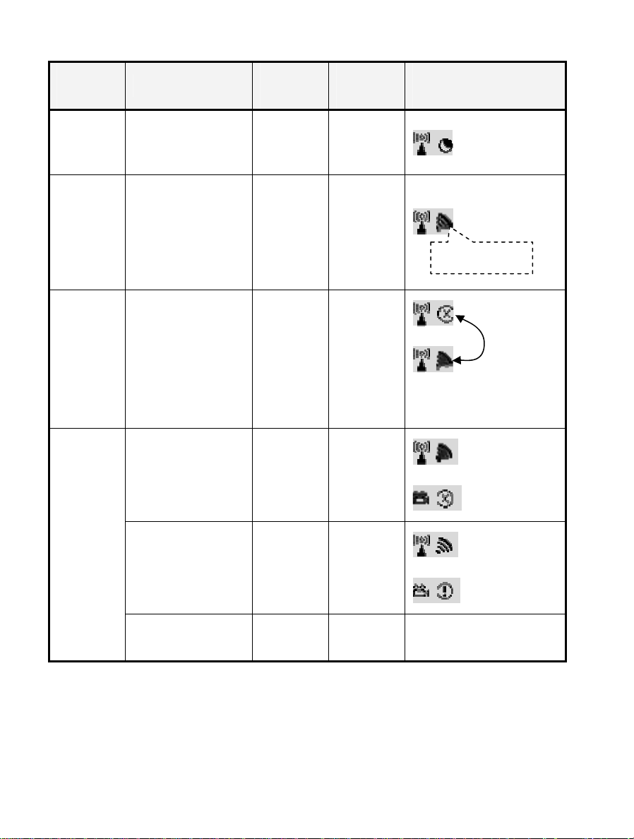
Item /
Mode
Status Description
Power LED
(on RX)
Status LED
(on RX)
OSD Display
(on RX)
Standby
Initial Boot
up / Warm
up
Searching
available
channels
Wireless
linked
Mode
For power saving mode.
It will spend 15 ~ 20
seconds for system boot
up.
Continuing search
available channels If
system can’t establish
link over 80s after
initialization.
(Note A & D)
No input from selected
source
(Note B)
Video format not
recognized
(Note C)
Static Red off
Blinking
Blinking
Blue
Blinking
Blinking
Blue
Blinking
Static Blue
(Quickly)
Blinking
Static Blue
(Slowly)
4 level, looping.
Looping display
these two OSD
Video format is
recognized
Static Blue Static Blue
-
Note:
A. If the RF connection over 80sec and still not established, it might link lost or the transmitter is
most likely out of range. You may have to verify the range and adjust or shorten the distance
between your HDTV set with the transmitter and the receiver. The maximum video
transmission range for 1080p content is up to 66 feet in line of sight (LOS). < The minimum
range is 6.5 feet. >
15
Page 18

B. Please make sure the computer have been power on and switched the signal output to HDMI
out; also try to re-plug the HDMI cable to make sure the HDMI connector had settled well.
C. If there is no video displayed and OSD displayed “Not Supported Format”, this is an indication
that the video frame rate from the computer is not supported, please refer chapter 5 to switch
a supported video timing.
D. If you have more than one pair of WHDI DEVICE, each transmitter and receiver should be at
least 6.5 feet away from one another. If both the transmitter and the receiver exist in the same
room, the suggested the distance between the two is 6.5 feet minimum.
(9) On Screen Display (OSD) vs. RCU Instruction
On Active mode, Press the POWER button on the top of Receiver or press RCU Power button
point to receiver, receiver enter Standby mode and transmitter’s HDMI out is on.
OSD Displayed: (Display 3secs and then enter Standby mode.)
ON
On Active mode, Press the POWER button on the top of Transmitter or press RCU Power button
point to transmitter, both transmitter and receiver will enter Standby mode.
OSD Displayed: (Display 3secs and then enter Standby mode.)
OFF
Press the INFO button on the RCU, and Signal Quality, Source, Channel and resolution will be
displayed for user reference.
OSD Displayed: (Press again for exit.)
HDMI1 CH10 1280x1024
= OFF
16
Page 19

Press the SOURCE button on the RCU or on the top of transmitter (or receiver) for audio/video
source input selection.
OSD Displayed:
HDMI1 CH10 1280x1024
or
HDMI2 CH10 1280x1024
Press the IR button of RCU for change IR Blaster frequency, enable to switch IR Blaster
frequency 47K to 56K to 36K recurring. (Note : IR blaster frequency default setting is 47KHz)
Press once for current IR frequency status display. The OSD shows:
HDMI1 CH10 1280x1024
= 47KHz
Press IR key again to switch IR blaster frequency. The OSD shows:
HDMI1 CH10 1280x1024
= 56KHz
NOTE: Only the status of the RECEIVER (receiver) connected to the HDTV can be displayed on the
OSD. The status of the TRANSMITTER (transmitter) HDMI out cannot be displayed.
17
Page 20
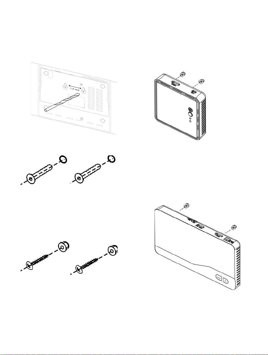
Step 5: Mounting the WHDI DEVICE to the Wall
(1) Refer the drawing of the bottom page
that have relative position of the main
holes and attach this paper on wall.
(2) Drill pilot holes.
(5) Place WHDI DEVICE main holes over the
protruding screws and slide down into
position.
(3) Insert the supplied two Anchors into the
wall.
(4) Insert two screws into the anchors. Leave
1/8” length for mounting the Transmitter
or receiver.
18
Page 21
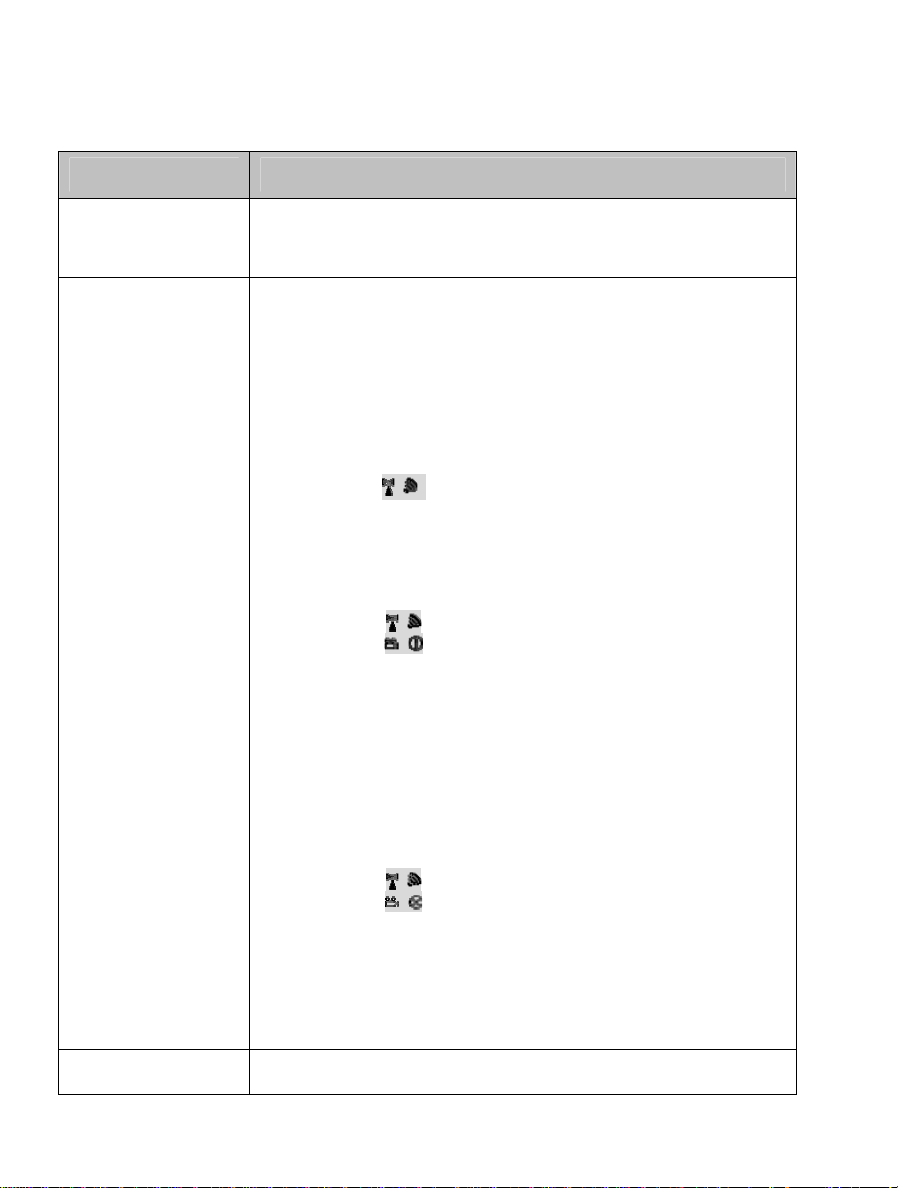
4. Troubleshooting
Problem Solution
The WHDI DEVICE
power indicator LED
doesn't light up.
No video is displayed
on your TV screen.
Poor picture quality or
Check if the power plugs of TRANSMITTER/RECEIVER are properly
inserted into a functioning power outlet.
Verify that the proper cables have been selected and installed
between the TRANSMITTER (transmitter) input and your
High-Definition device output.
On your TV side (connected to the RECEIVER), select the HDMI as
input source.
Verify the POWER LED and SOURCE LED indicator of WHDI DEVICE.
Power LED Flashing in Blue
OSD displayed: (4 levels looping)
* Ensure the transmission range between the transmitter and the
receiver is NOT over 66 feet (LOS-line of sight) transmission distance.
* Try to move the transmitter closer to the receiver.
POWER LED in Solid Blue + Slow and Flashing SOURCE LED
OSD displayed :
* Ensure your video resolution and frame rate is recognized/ supported
and within the transmission range.
*Connect the source device to your TV to check and modify the video
format compatibility.
*Check if your video resolution with HDMI input from your device is set
among 1080p, 1080i, 720p, 576p, or 480p. Please refer Chapter 5 for
the detail supported Resolution.
POWER LED in Solid Blue STATUS LED Flash Quickly
OSD displayed :
* Ensure the proper cables are connected between the transmitter and
your AV source devices.
* Ensure your source devices connected to the WHDI DEVICE
transmitter are powered on.
* Ensure the proper cables are connected between the receiver and
nd
your 2
Check if your video resolution with HDMI input from your device is
HDTV near the receiver.
either 1080p, 1080i, 720p, 576p, or 480p. Please refer to the
19
Page 22

intermittent video. “Supported Resolution” chapter where the video frame rate from
your HD AV device WHDI DEVICE can support is defined.
Ensure the transmission distance is less than 66 feet (LOS).
Check your TV’s volume is properly set and not set in "MUTE" mode.
Check if your source player’s audio volume has been turned up..
No audio.
IR Blaster can’t control
Source device.
Ensure the bit rate of audio from the source device can be supported
by WHDI DEVICE. Please refer to the details in Chapter 6, Audio Bit
Rate Support.
Check where is IR sensor of Source device. Make sure IR Blaster
sensor is close and straight to Source device’s IR sensor. Please refer
Chapter 3, step 3 for reference setup.
Change IR Blaster frequency to meet Source device’s requirement.
See the page 20 for the IR blaster frequency switch.
20
Page 23
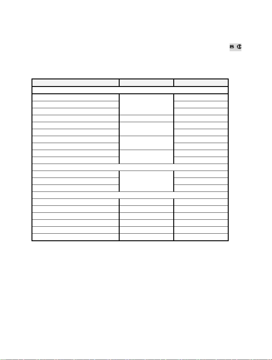
5. Supported Resolution
If the SOURCE LED continues to blink in blue (slower than “no signal” mode); OSD display: ,
and there is no video displayed or the video quality suffers, it indicates that the video frame rate
from your A/V source device is not supported. Ensure that the consumer timing of your HD device
is compliant with the standard listed below:
Video Format Timings Resolution Support
Primary CEA Video T iming
640x480p @ 59.94 / 60Hz YES
720x480p @ 59.94Hz YES
720x480p @ 60Hz
720x576p @ 50Hz 576p YES
1280x720p @ 50Hz YES
1280x720p @ 59.94 / 60Hz
1920x1080i @ 50Hz YES
1920x1080i @ 59.94 / 60Hz
1920x1080p @ 50Hz YES
1920x1080p @ 59.94 / 60Hz
Secondary CEA Video Timing
1920x1080p @ 23.98 / 24Hz YES
1920x1080p @ 25Hz YES
1920x1080p @ 29.97 / 30Hz
VESA Timing (DVI only)
640x480 @ 59.94 / 72.809Hz VGA YES
800x600 @ 60.317 / 72.188Hz SVGA YES
1024x768 @ 60 / 70.069Hz XGA YES
1280x768 @ 60 Hz WXGA YES
1280x1024 @ 60 Hz SXGA YES
1600x1200 @ 60Hz UXGA YES
480p
720p
1080i
1080p / 60
1080p / 24
YES
YES
YES
YES
YES
21
Page 24
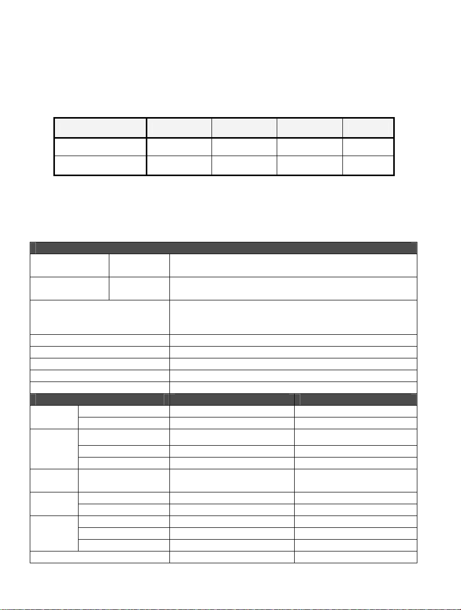
6. Audio Bit Rate Support
Digital Audio from HDMI inputs: Up to 6Mbit/s bit-rate support.
Support AC3 and DTS.
2-channel PCM: 16~24 bits audio sample with 32~96KHz sampling rate as below:
2channel PCM 32KHz 44.1KHz 48KHz 96KHz
16 bits YES YES YES YES
24 bits YES YES YES YES
7. Product Specification
General Specifications
Supported Video
Resolutions
Supported Audio
Formats
Transmission Distance
System Latency No latency (<1ms)
Antenna High Performance Internal Antennas
Operating Frequencies 4.9~ 5.9GHz (Include non-DFS and DFS Frequency Bands)
Power Supply 100~ 240V AC in, 5V 2A DC out Power Adaptor
Operating Temperature 0~40°C
Interfaces TRANSMITTER RECEIVER
Interfaces
Control
Signal
Interfaces
Power
Interface
Switches
LEDs
Dimensions (mm³) 192(W) x 96.5(L) x 31.5(H) 95(W) x 95(L) x 31.5(H) mm
HDMI Input 1080p, 1080i, 720p, 576p, 480p
Digital Audio Up to 6 Mbps AC3 and DTS
The maximum video transmission range is 20 meters (66 feet)
(The minimum range is 2 meters)
Line of sight (LOS) scenarios
HDMI Input TWO (Type A) - A/V
HDMI Output One (Type A) One (Type A)
IR Sensor YES YES
IR Blaster Extender 2.5mm Jack IR Sensor Extender - YES
Power Input 5V DC Jack 5V mini USB
Front Power Switch YES (One Tack Switch) YES (One Tack Switch)
Front Source Switch YES (One Tack Switch) YES (One Tack Switch)
Power LED 1 x LED (Two Tone: Blue/Red) 1 x LED (Two Tone: Blue/Red)
Source LED 2 x Blue LED 2 x Blue LED
Signal Quality Status - OSD Displayed
22
Page 25

25
Page 26

25
Page 27

25
Page 28

23
IB0438099
 Loading...