


Wireless LAN Device Series
Multi-Mode AP
ZWA-G220 User’s Manual
Version. 1.4.3b (2007.07.31)

TABLE OF CONTENTS
NOTICE..................................................................................................................................................3
PREFACE..........................................................................................................錯誤! 尚未定義書籤。
CH 1. ZWA-G220 INSTALLATION....................................................................................................6
PACKING LIST.......................................................................................................................................6
BACK PANEL CONNECTIONS .................................................................................................................6
HARDWARE INSTALLATION..................................................................................................................7
CH 2. FIRST TIME CONFIGURATION ............................................................................................8
BEFORE START TO CONFIGURE .............................................................................................................8
KNOWING THE NETWORK APPLICATION ...............................................................................................8
BASIC SETTINGS.................................................................................................................................28
ADVANCED SETTINGS.........................................................................................................................31
CONFIGURING WIRELESS SECURITY...................................................................................................34
CONFIGURING AS WLAN CLIENT ADAPTER.......................................................................................37
QUICK START T O CONFIGURE..............................................................................................................37
MAC CLONE FOR SINGLE ETHERNET CLIENT ....................................................................................39
EXTEND THE REMOTE AP (BSS).........................................................................................................40
CH 3. CONFIGURING WDS..............................................................................................................42
WDS NETWORK TOPOLOGY................................................................................................................42
WDS APPLICATION.............................................................................................................................44
CH 4. ADVANCED CONFIGURATIONS.........................................................................................46
CONFIGURING LAN TO WAN FIREWALL............................................................................................46
PORT FILTERING .................................................................................................................................46
IP FILTERING ......................................................................................................................................47
MAC FILTERING.................................................................................................................................48
NAT (NETWORK ADDRESS TRANSLATION).........................................................................................49
CONFIGURING PORT FORW ARDING (VIRT UAL SERVER)..............................................................................50
MULTIPLE SERVERS BEHIND NAT EXAMPLE: .....................................................................................50
CONFIGURING DMZ...........................................................................................................................51
CONFIGURING WAN INTERFACE.........................................................................................................52
STATIC IP............................................................................................................................................52
DHCP CLIENT (DYNAMIC IP).............................................................................................................53
PPPOE................................................................................................................................................54
PPTP..................................................................................................................................................55
CONFIGURING CLONE MAC ADDRESS ...............................................................................................57
CONFIGURING DHCP SERVER ............................................................................................................59
1

ANDWIDTH CONTROL.......................................................................................................................60
B
QOS (QUALITY OF SERVICE)...............................................................................................................60
STATIC ROUTE SETUP .........................................................................................................................64
DYNAMIC ROUTE SETUP ....................................................................................................................65
VPN PASS-THROUGH..........................................................................................................................66
USING CLI MENU...............................................................................................................................66
THE SYSTEM MANAGEMENT ..............................................................................................................68
SNMP AGENT ....................................................................................................................................68
MISCELLANEOUS SETTINGS................................................................................................................71
PING WATCHDOG ...............................................................................................................................72
AIMING TOOL.....................................................................................................................................73
CONNECTING PROFILE........................................................................................................................74
FIRMWARE UPGRADE .........................................................................................................................75
CONFIGURATION DATA BACKUP & RESTORE......................................................................................76
AUTO DISCOVERY TOOL.....................................................................................................................77
2

Notice
FCC Warning
Changes or modifications to this unit not expressly approved by the party
responsible for compliance could void the user authority to operate the
equipment.
This device complies with Part 15 of the FCC Rules. Operation is subject to the
following two conditions: (1) This device may not cause harmful interference,
and (2) this device must accept any interference received, including
interference that may cause undesired operation.
The user’s manual or instruction manual for an intentional or unintentional
radiator shall caution the user that changes or modifications not expressly
approved by the party responsible for compliance could void the user’s
authority to operate the equipment.
3

FCC Statement
This equipment has been tested and found to comply with the limits for a Class
B digital device, pursuant to Part 15 of the FCC Rules. These limits are
designed to provide reasonable protection against harmful interference in a
residential installation. This equipment generates uses and can radiate radio
frequency energy and, if not installed and used in accordance with the
instructions, may cause harmful interference to radio communications.
However, there is no guarantee that interference will not occur in a particular
installation. If this equipment does cause harmful interference to radio or
television reception, which can be determined by turning the equipment off and
on, the user is encouraged to try to correct the interference by one or more of
the following measures:
z Reorient or relocate the receiving antenna.
z Increase the separation between the equipment and receiver.
z Connect the equipment into an outlet on a circuit different from that to
which the receiver is connected.
z Consult the dealer or an experienced radio/TV technician for help.
FCC RF Radiation Exposure Statement
This equipment complies with FCC radiation exposure limits set forth for an
uncontrolled environment. This equipment should be installed and operated
with minimum distance 20cm between the radiator & your body. For product
available in the USA/Canada market, only channel 1~11 can be operated.
Selection of other channels is not possible. The antenna(s) used for this
transmitter must not be co-located or operating in conjunction with any other
antenna or transmitter. Shielded interface cables must be used in order to
comply with emission limits.
4

CE Statement
Hereby, ZINWELL, declares that this device is in compliance with the essential
requirement and other relevant provisions of the R&TTE Directive 1999/5/EC.
This device will be sold in the following EEA countries:Austria, Italy, Belgium,
Liechtenstein, Denmark, Luxembourg, Finland, Netherlands, France, Norway,
Germany, Portugal, Greece, Spain, Iceland, Sweden, Ireland, United Kingdom,
Cyprus, Czech Republic, Estonia, Hungary, Latvia, Lithuania, Malta, Slovakia,
Poland, Slovenia, Bulgaria, Romania.
5
Ch 1. ZWA-G220 Installation
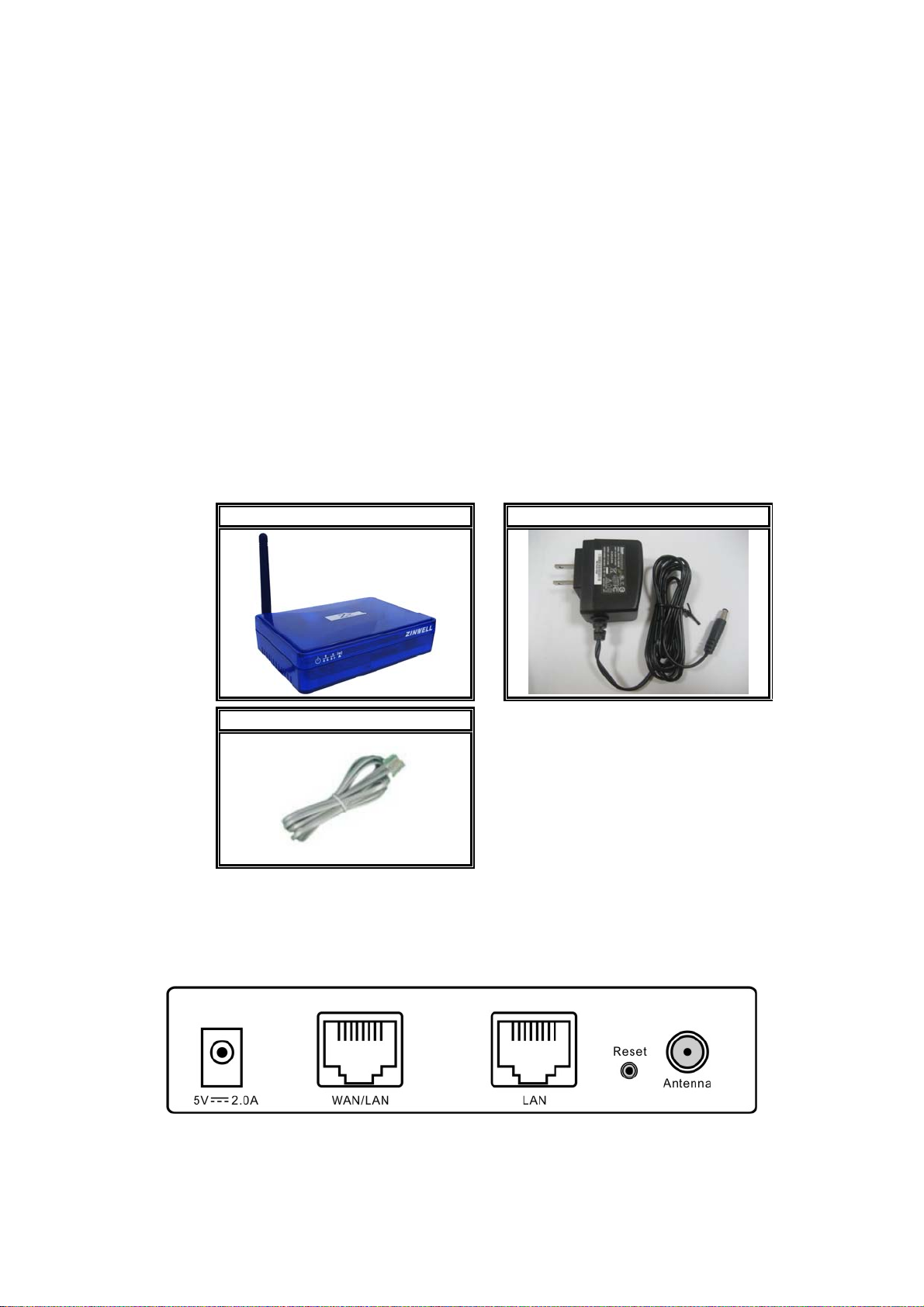
Packing List
Before you start to install the device, make sure the package contains the
following items:
● ZWA-G220 Multi-Mode AP unit * 1
● Power Adapter * 1
● RJ-45 Cable * 1
Multi-Mode AP Power Adapter
RJ-45 Cable
Back panel connections
From Left to Right:
DC jack: ZW-220 can use power source in DC jack. Please supply the power in
6
5V and 2A
WAN/LAN: This port could be WAN or LAN port depending on the
configuration. It will be WAN port in router mode and LAN port in
bridge mode.
LAN: This port is always LAN in ZW-220. In Bridge mode, it bridges to WLAN
and “WAN/LAN” port. In Router mode, it bridges to WLAN only, In WISP
mode, it bridges to “WAN/LAN” port only.
Reset: Press Reset button to revert it to factory default.
Antenna: This SMA Reverse allows the user to connect antenna or RF cable.
At least connect an antenna to help ZW-220 to send and receive RF
signal.
ZW-220 integrates LNA/PA (Low Noise Amplifier) module and has at
lease 3dB RF sensitivity better than the regular WLAN products.
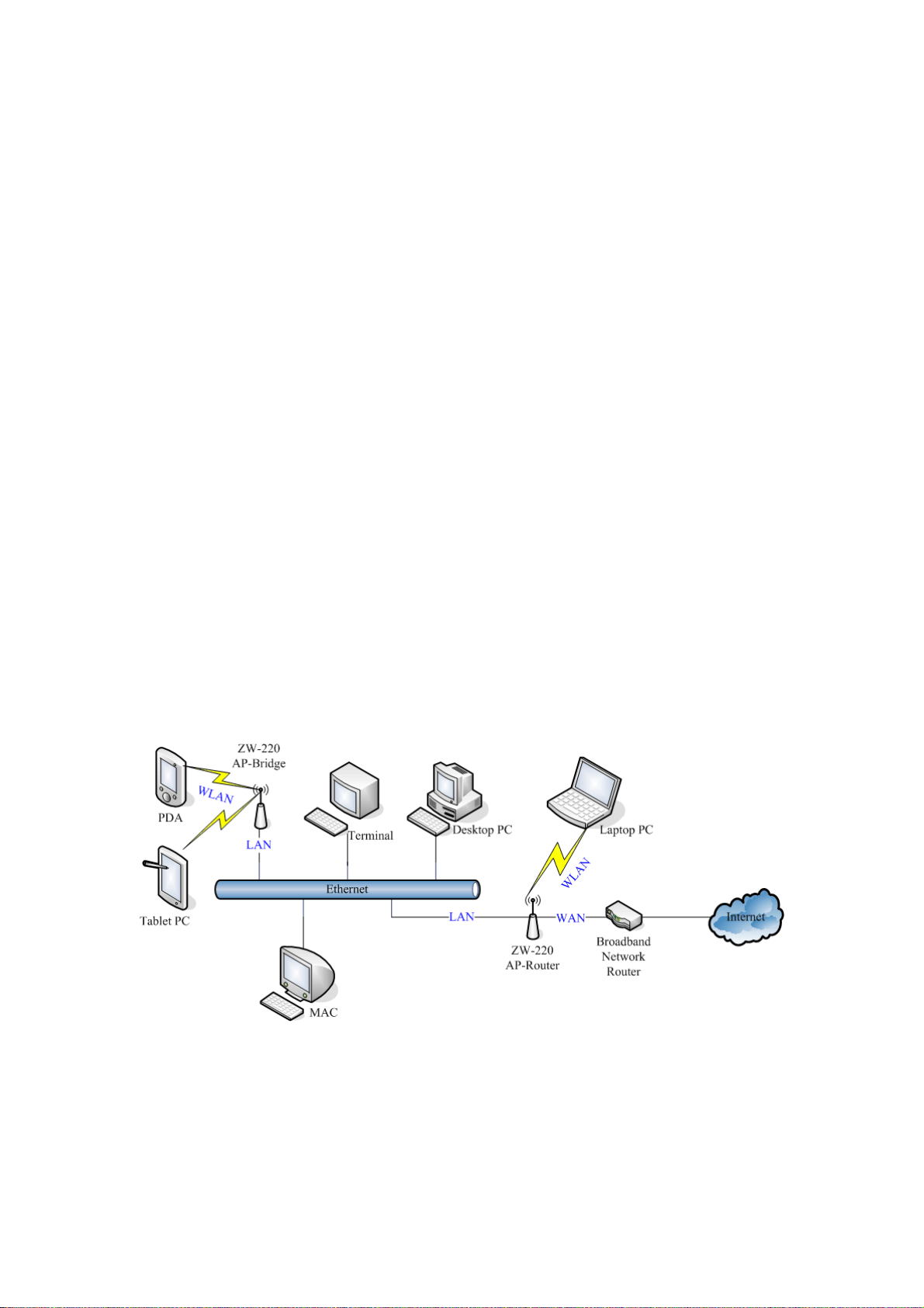
Hardware Installation
Once you check off everything from the package, you can start to install the
device. You can use the wall mount hole on the bottom of the device to
mount the device on the wall, or just put the device on the desktop. The
administrator can refer to the figure below while constructing your WLAN
environment.
7

Ch 2. First Time Configuration
Before Start to Configure
There are two ways to configure the device, one is through web-browser,
and the other is through Secure Shell CLI interface. To access the
configuration interfaces, make sure you are using a computer connected to
the same network as the device. The default IP address of the device is
192.168.2.254, and the subnet-mask is 255.255.255.0.
The device has three operation modes (Router/Bridge/WISP). In bridge
mode, also known as AP Client, you can access the device by WLAN
(Wireless Local Area Network) and both wired LAN ports. And in
router/WISP modes, the device can be accessed by WLAN, LAN and WAN.
The default IP addresses for the device are 192.168.2.254 (for LAN),
172.1.1.1(for WAN), so you need to make sure the IP address of your PC is
in the same subnet as the device, such as 192.168.2.X (for LAN), 172.1.1.X
(for WAN).
Please note that the DHCP server inside the device is default to up and
running. Do not have multiple DHCP servers in your network environment,
otherwise it will cause abnormal situation.
We also provide an auto-discovery tool which is for finding out the IP of the
device. In case, you’ve forgot the IP of the device or the IP of the device has
been changed, you can use the tool to find out the IP of the device even your
PC is not in the same subnet as the device is.
Knowing the Network Application
The device can act as the following roles, and it supports WDS (Wireless
Distribution System) function.
z Access Point
z WDS mode
z Bridge/Router
z WISP
z AP Client
The device provides 3 different operation modes and the wireless radio of
8

device can act as AP/Client/WDS. The operation mode is about the
communication mechanism between the wired Ethernet NIC and wireless
NIC, the following is the types of operation mode.
Router
The wired Ethernet (WAN) port is used to connect with ADSL/Cable modem
and the wireless NIC is used for your private WLAN. The other wired
Ethernet (LAN) port bridges to the private WLAN. The NAT is existed
between WAN and WLAN/LAN and all the wireless and wired clients share
the same public IP address through the WAN port to ISP. The default IP
configuration for WAN port is static IP. You can access the web server of
device through the default WAN IP address 172.1.1.1 and modify the setting
base on your ISP requirement.
Bridge
The two wired Ethernet ports and wireless NIC are bridged together. Once
the mode is selected, all the WAN related functions will be disabled.
WISP (Wireless ISP)
This mode can let you access the AP of your wireless ISP and share the
same public IP address from your ISP to the PCs connecting with both the
wired Ethernet ports of the device. To use this mode, first you must set the
wireless radio to be client mode connecting to the AP of your ISP as the
WAN connection and then you can configure the WAN IP configuration to
meet your ISP requirement.
The wireless radio of the device acts as the following roles.
AP (Access Point)
The wireless radio of device serves as communications “hub” for wireless
clients and provides a connection to a wired LAN.
AP Client
This mode provides the capability to connect with the other AP using
infrastructure/Ad-hoc networking types. With bridge operation mode, you
can directly connect one of the wired Ethernet port to your PC and the
device becomes a wireless adapter. And with WISP operation mode, you
can connect one of the wired Ethernet port to a hub/switch and all the PCs
connecting with hub/switch can share the same public IP address from your
ISP.
9
WDS (Wireless Distribution System)
This mode combines up to 8 AP to a single wireless network; the device
forwards the packets to another AP with WDS function. When this mode is
selected, all the wireless clients can’t survey and connect to the device. The
device only allows the WDS connection.
WDS+AP
This mode combines WDS plus AP modes, it not only allows WDS
connections but also the wireless clients can survey and connect to the
device.
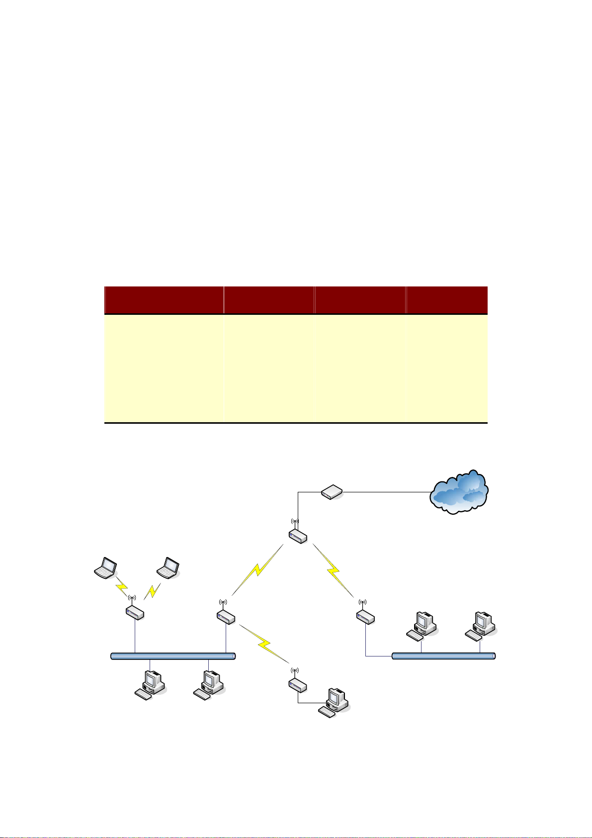
The following table shows the supporting combination of operation and
wireless radio modes.
Bridge Router WISP
AP
WDS
Client
AP+WDS
V V X
V V X
V X V
V V X
Hereafter are some topologies of network application for your reference.
Internet
Broadband
Modem
Router Mode
With
WDS + AP
Bridge Mode
With
AP
Bridge Mode
With
WDS + AP
WISP Mode
Bridge Mode
10
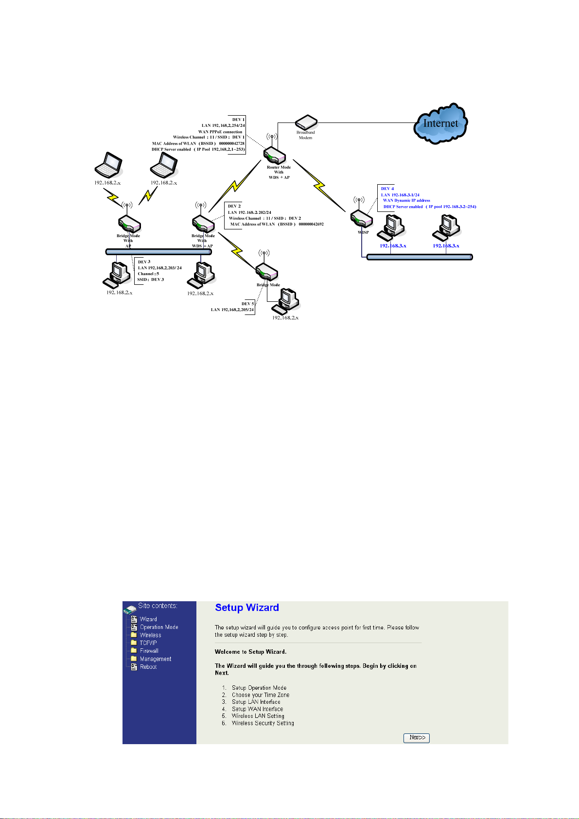
Examples of Configuration
This example demonstrates how to set up a network with different device
configurations. There are 2 DHCP servers (DEV1/DEV4) in the network to
control the IP configuration of 2 domains (192.168.2.x/192.168.3.x). Once
the setting is done, all the PCs can visit Internet through DEV1.
We assume all the devices keep the factory default setting. To make sure
that user can continuing press the rest button for more than 5 seconds to
restore the factory default setting.
The following descriptions show the steps to configure DEV1 to DEV5.
Configure DEV1:
1. Connect the ADSL modem to Ethernet port of device using Ethernet
cable.
2. Access the web server (http://192.168.2.254) of device from the
wireless station.
3. Use Wizard page to setup device.
11

4. Press “Next>>” button then set the “Operation Mode” to “Router” mode.
5. Press “Next>>” button then disable “Time Zone” function.
6. Press “Next>>” button then set the IP address of LAN interface.
7. Press “Next>>” button then select the “PPPoE” for “WAN Access Type”
and fill in the “User Name” and “Password” fields.
12

8. Press “Next>>” button then select the “AP+WDS” for “mode” and
change the SSID to “DEV1”.
9. Press “Next>>” button then select “None” for “Encryption” then press
“Finished” button.
10. Wait for refreshing web page.
11. Use “WDS Settings” page to configure WDS.
13

12. Enable WDS function and add the BSSID of DEV2 to “Current WDS AP
List”.
13. Since we access the device by wireless connection, it may temporarily
disconnect when applying the WDS setting. After re-connecting to the
device, use the “Status” page to check the settings.
14

Configure DEV2:
1. Access the web server (http://192.168.2.254) of device from the
Ethernet port.
Caution
If you configure multiple devices in the same PC, since the devices
have the same default IP address but different MAC addresses, it may
cause you not able to access the web server of device. If the situation
happens, please try to clean the ARP table of your PC by DOS
command “arp –d” then you can access the web server of device
using the default IP address.
2. Use Wizard page to setup device.
3. Press “Next>>” button then set the “Operation Mode” to “Bridge” mode.
4. Press “Next>>” button then disable “Time Zone” function.
15

5. Press “Next>>” button then set the IP address of LAN interface.
6. Press “Next>>” button then select the “AP+WDS” for “mode” and
change the SSID to “DEV2”.
7. Press “Next>>” button then select “None” for “Encryption” then press
“Finished” button.
8. Wait for refreshing web page.
16

9. Access the web server by new IP address “192.168.2.202” then use
“LAN Interface” page to disable DHCP Server.
10. Wait for refreshing web page.
11. Use “WDS Settings” page to configure WDS.
17

12. Enable WDS function and add the BSSID of DEV1 to “Current WDS AP
List”.
13. Use the “Status” page to check the settings.
18

Configure DEV3:
1. Access the web server (http://192.168.2.254) of device from the
Ethernet port.
Caution
If you configure multiple devices in the same PC, since the devices
have the same default IP address but different MAC addresses, it
may cause you not able to access the web server of device. If the
situation happens, please try to clean the ARP table of your PC by
DOS command “arp –d” then you can access the web server of
device using the default IP address.
2. Use “LAN Interface” page to set the IP address of LAN interface and
disable DHCP server.
3. Wait for refreshing web page.
19

4. Access the web server by new IP address “192.168.2.203” then use
“Basic Settings” page to change SSID and CHANNEL.
5. Use the “Status” page to check the settings.
20

Configure DEV4:
1. Access the web server (http://192.168.2.254) of device from the
Ethernet port.
Caution
If you configure multiple devices in the same PC, since the devices
have the same default IP address but different MAC addresses, it
may cause you unable to access the web server of device. If the
situation happens, please try to clean the ARP table of your PC by
DOS command “arp –d” then you can access the web server of
device using the default IP address.
2. Use Wizard page to setup device.
3. Press “Next>>” button then set the “Operation Mode” to “Wireless ISP”
mode.
4. Press “Next>>” button then disable “Time Zone” function.
21

5. Press “Next>>” button then set the IP address of LAN interface.
6. Press “Next>>” button then select the “DHCP Client” for “WAN Access
Type”.
7. Press “Next>>” button then select the “Client” for “mode” and change
the SSID to “DEV4”.
8. Press “Next>>” button then select “None” for “Encryption” then press
“Finished” button.
22

9. Wait for refreshing web page.
10. Change the IP address of your PC to 192.168.3.x then access the web
server by the new IP address “192.168.3.1” and use “Status” page
check the setting.
11. If the “State” of “Wireless Configuration” is not “Connected” or you want
to refresh the “RSSI “, please use “Site Survey” page to re-connect a
AP.
23

Configure DEV5:
1. Access the web server (http://192.168.2.254) of device from the
Ethernet port.
Caution
If you configure multiple devices in the same PC, since the devices
have the same default IP address but different MAC addresses, it
may cause you unable to access the web server of device. If the
situation happens, please try to clean the ARP table of your PC by
DOS command “arp –d” then you can access the web server of
device using the default IP address.
2. Use Wizard page to setup device.
3. Press “Next>>” button then set the “Operation Mode” to “Wireless ISP”
mode.
4. Press “Next>>” button then disable “Time Zone” function.
24

5. Press “Next>>” button then set the IP address of LAN interface.
6. Press “Next>>” button then select the “Client” for “mode” and change
the SSID to “DEV5”.
7. Press “Next>>” button then select “None” for “Encryption” then press
“Finished” button.
8. Wait for refreshing web page.
25

9. Access the web server by the new IP address “192.168.2.205” and use
“LAN Interface” page to disable DHCP Server.
10. Wait for refreshing webpage.
11. Use “State” page to check setting.
26

12. If the “State” of “Wireless Configuration” is not “Connected” or you want
to refresh the “RSSI “, please use “Site Survey” page to re-connect a
AP.
27

Basic Settings
Disable Wireless LAN Interface
Disable the wireless interface of device
Band:
The device supports 2.4GHz(B), 2.4GHz(G) and 2.4GHz(B+G) mixed modes.
Mode:
The radio of device supports different modes as following:
1. AP
The radio of device acts as an Access Point to serves all wireless clients
to join a wireless local network.
2. Client
Support Infrastructure and Ad-hoc network types to act as a wireless
adapter.
3. WDS
Wireless Distribution System, this mode joins to a WDS network which
combines up to 8 WDS-AP, only devices with WDS function supported
can connect to it, all the wireless clients can’t survey and connect the
device when the mode is selected.
4. AP+WDS
Support both AP and WDS functions, the wireless clients and devices
with WDS function supported can survey and connect to it.
28

z Infrastructure:
This type requires the presence of 802.11b/g Access Point. All
communication is done via the Access Point.
Ethernet
AP
AP Client #1
AP Client #2
z Ad Hoc:
This type provides a peer-to-peer communication between wireless
stations. All the communication is done from Client to Client without any
Access Point involved. Ad Hoc networking must use the same SSID and
channel for establishing the wireless connection.
PC #1
AP Client #1
AP Client #2AP Client #3
PC #3 PC #2
In client mode, the device can’t support the Router mode function
including Firewall and WAN settings.
SSID:
The SSID is a unique identifier that wireless networking devices use to
establish and maintain wireless connectivity. Multiple access point/bridges on
a network or sub-network can use the same SSID. SSIDs are case sensitive
and can contain up to 32 alphanumeric characters. Do not include spaces in
your SSID.
29

Channel Number
The following table is the available frequencies (in MHz) for the 2.4-GHz radio:
Channel No. Frequency Country Domain
1 2412 Americas, EMEA, Japan, and China
2 2417 Americas, EMEA, Japan, and China
3 2422 Americas, EMEA, Japan, Israel, and China
4 2427 Americas, EMEA, Japan, Israel, and China
5 2432 Americas, EMEA, Japan, Israel, and China
6 2437 Americas, EMEA, Japan, Israel, and China
7 2442 Americas, EMEA, Japan, Israel, and China
8 2447 Americas, EMEA, Japan, Israel, and China
9 2452 Americas, EMEA, Japan, Israel, and China
10 2457 Americas, EMEA, Japan, and China
11 2462 Americas, EMEA, Japan, and China
12 2467 EMEA and Japan
13 2472 EMEA and Japan
14 2484 Japan only
※ EMEA (Europe, the Middle East and Africa).
When set to “Auto”, the device will find the least-congested channel for use.
Associated Client
Show the information of active wireless client stations that connected to the
device.
30

Advanced Settings
These settings are only for more technically advanced users who have
sufficient knowledge about wireless LAN. These settings should not be
changed unless you know what effect the changes will have on your
device. The default setting is optimized for the normal operation. For
specific application, setting configuration will required highly attention to
reach optimistic condition.
Note:
Any unreasonable value change to default setting will reduce the
throughput of the device.
Authentication Type
The device supports two Authentication Types “Open system” and “Shared
Key”. When you select “Share Key”, you need to setup “WEP” key in “Security”
page (See the next section). The default setting is “Auto”. The wireless client
can associate with the device by using one of the two types.
Fragment Threshold
The fragmentation threshold determines the size at which packets are
fragmented (sent as several pieces instead of as one block). Use a low setting
in areas where communication is poor or where there is a great deal of radio
interference. This function will help you to improve the network performance.
31

RTS Threshold
The RTS threshold determines the packet size at which the radio issues a
request to send (RTS) before sending the packet. A low RTS Threshold setting
can be useful in areas where many client devices are associating with the
device, or in areas where the clients are far apart and can detect only the
device and not each other. You can enter a setting ranging from 0 to 2347
bytes.
Beacon Interval
The beacon interval is the amount of time between access point beacons in
mini-seconds. The default beacon interval is 100.
ACK Timing
Acknowledgement Timing, is the amount of time that device wait client’s
response. This concept is related to EIFS (Extended Inter-Frame Space).
The EIFS interval shall begin while the device is idle after detection of the
erroneous frame. The EIFS is defined to provide enough time for another
device to acknowledge what was, to this device, an incorrectly received
frame before this device commences transmission. The default setting of
ACK timing is 0. You may need to change this value due to the environment
or distance.
Client Expired Time
The client expired time determines time interval the client need to re-associate
with the device while client is idle. The default client expired time is 300 sec.
MTU Size
Maximum Transmission Unit, the default MTU size is 1500. The MTU setting
controls the maximum Ethernet packet size your PC will send. Why a limit?
Because although larger packets can be constructed and sent, your ISP and
Internet backbone routers and equipment will fragment any larger than their
limit, then these parts are re-assembled by the target equipment before
reading. This fragmentation and re-assembly is not optimal. You may need to
change the MTU for optimal performance of your wireless LAN traffic.
Data Rate
The standard IEEE 802.11b/11g supports 1, 2, 5.5, 11 / 6, 9, 12, 18, 24, 36, 48
and 54 Mbps data rates. You can choose the rate that the device uses for data
transmission. The default value is “auto”. The device will use the highest
possible selected transmission rate.
Broadcast SSID
Broadcasting the SSID will let your wireless clients find the device
automatically. If you are building a public Wireless Network, disable this
function can provide better security. Every wireless stations located within the
coverage of the device must connect this device by manually configure the
32

SSID in your client settings.
IAPP (Inter-Access Point Protocol)
This function will let Wireless Stations roam among a network environment
with multiple devices. Wireless Stations are able to switch from one device to
another as they move between the coverage areas. Users can have more
wireless working range. An example is as the following figure.
You should comply with the following instructions to roam among the wireless
coverage areas.
Note: For implementing the roaming function, the setting MUST comply the
following two items.
z All the devices must be in the same subnet network and the SSID must
be the same.
z If you use the 802.1x authentication, you need to have the user profile
in these devices for the roaming station.
Block WLAN Relay (Isolate Client)
The device supports isolation function. If you are building a public Wireless
Network, enable this function can provide better security. The device will block
packets between wireless clients (relay). All the wireless clients connected to
the device can’t see each other.
Transmit Power
The default transmit power of this device is 26.65dBm for CCK (802.11b) and
21.96dBm for OFDM (802.11g). In case of decrease the wireless distance and
coverage of this device, turn down the power level for CCK and OFDM. For
CCK, 4 levels are available to turn down the power from default 26.65dBm to
25.65, 24.65, 23.65,22.65dBm. For OFDM, 3 levels are available to turn down
the power from default 21.96dBm to 20.96, 19.96, 18.96dBm.
If you want to restore the wireless distance and coverage of the device, select
a higher level or the default level of transmit power.
33

Configuring Wireless Security
This device provides complete wireless security function include WEP, 802.1x,
WPA-TKIP, WPA2-AES and WPA2-Mixed in different mode (see the Security
Support Table).
The default security setting of the encryption function is disabled. Choose your
preferred security setting depending on what security function you need.
WEP Encryption Setting
Wired Equivalent Privacy (WEP) is implemented in this device to prevent
unauthorized access to your wireless network. The WEP setting must be as
same as each client in your wireless network. For more secure data
transmission, you can change encryption type to “WEP” and click the “Set
WEP Key” button to open the “Wireless WEP Key setup” page.
When you decide to use the WEP encryption to secure your WLAN, please
refer to the following setting of the WEP encryption:
34

z 64-bit WEP Encryption:64-bit WEP keys are as same as the encryption
method of 40-bit WEP. You can input 10 hexadecimal digits (0~9, a~f or
A~F) or 5 ACSII chars.
z 128-bit WEP Encryption : 128-bit WEP keys are as same as the
encryption method of 104-bit WEP. You can input 26 hexadecimal digits
(0~9, a~f or A~F) or 10 ACSII chars.
z The Default Tx Key field decides which of the four keys you want to use in
your WLAN environment.
WEP Encryption with 802.1x Setting
The device supports external RADIUS Server that can secure networks
against unauthorized access. If you use the WEP encryption, you can also use
the RADIUS server to check the admission of the users. By this way every
user must use a valid account before accessing the Wireless LAN and
requires a RADIUS or other authentication server on the network. An example
is shown as following.
You should choose WEP 64 or 128 bit encryption to fit with your network
environment first. Then add user accounts and the target device to the
RADIUS server. In the device , you need to specify the IP address、Password
(Shared Secret) and Port number of the target RADIUS server.
35

WPA Encryption Setting
WPA feature provides a high level of assurance for end-users and
administrators that their data will remain private and access to their network
restricted to authorized users. You can choose the WPA encryption and select
the Authentication Mode.
WP A Authentication Mode
This device supports two WPA modes. For personal user, you can use the
Pre-shared Key to enhance your security setting. This mode requires only an
access point and client station that supports WPA-PSK. For Enterprise,
authentication is achieved via WPA RADIUS Server. You need a RADIUS or
other authentication server on the network.
z Enterprise (RADIUS):
When WPA Authentication mode is Enterprise (RADIUS), you have to add
user accounts and the target device to the RADIUS Server. In the device ,
you need to specify the IP address、Password (Shared Secret) and Port
number of the target RADIUS server.
z Pre-Share Key:
This mode requires only an access point and client station that supports
WPA-PSK. The WPA-PSK settings include Key Format, Length and Value.
They must be as same as each wireless client in your wireless network.
When Key format is Passphrase, the key value should have 8~63 ACSII
chars. When Key format is Hex, the key value should have 64 hexadecimal
digits (0~9, a~f or A~F).
36

Configuring as WLAN Client Adapter
This device can be configured as a wireless Ethernet adapter. In this mode,
the device can connect to the other wireless stations (Ad-Hoc network type)
or Access Point (Infrastructure network type) and you don’t need to install
any driver.
Quick start to configure
Step 1. In “Basic Settings” page, change the Mode to “Client” mode. And key in the
SSID of the AP you want to connect then press “Apply Changes” button to
apply the change.
1
2
3
4
5
Step 2. Check the state of connection in “Status” web page
37

The alternative way to configure as following:
Step 1. In “Wireless Site Survey” page, select one of the SSIDs you want to
connect and then press “Connect” button to establish the link.
1
2
4
Step 2. If the linking is established successfully. It will show the message
“Connect successfully”. Then press “OK”.
3
Step 3. Then you can check the linking information in “Status” page.
38

:
Note
If the available network requires authentication and data encryption, you need
to setup the authentication and encryption before step1 and all the settings
must be as same as the Access Point or Station. About the detail
authentication and data encryption settings, please refer the security section.
Authentication Type
In client mode, the device also supports two Authentication Types “Open
system” and “Shared Key”. Although the default setting is “Auto”, not every
Access Points can support “Auto” mode. If the authentication type on the
Access Point is knew by user, we suggest to set the authentication type as
same as the Access Point.
Data Encryption
In client mode, the device supports WEP and WPA Personal/Enterprise
except WPA2 mixed mode data encryption. About the detail data encryption
settings, please refer the security section.
MAC Clone for Single Ethernet Client
Enable/Disable Mac Clone (Single Ethernet Client) in Wireless-Basic Settings
page determines whether the Ethernet Client use it’s own MAC address or
AP-Client’s MAC address to transmit data. Enable MAC Clone, the single
Ethernet client can use its own MAC address. Disable MAC Clone, the single
Ethernet client must to use AP-Client’s MAC address.
While you use this device act as AP-Client and only one host connect to this
device via Ethernet, you need to check this option in this page, otherwise the
other device can’t recognize your host behind AP-Client. If you use hub/switch
connect multi-device to this AP-Client, you should uncheck this option.
39
 Loading...