

Zinwell ZRF32100 Users Manual

Table of Contents
TABLE OF CONTENTS
1. IMPORTANT INFORMATION .....................................................................................2
SAFETY PRECAUTIONS ......................................................................................................2
DANGER: B
2. INTRODUCTION
2.1 PACKING CONTENT
2.2 OVERVIEW
3. INSTALLATION............................................................................................................ 10
4. TROUBLESHOOTING .................................................................................................21
5. SUPPORTED RESOLUTION.......................................................................................23
6. AUDIO BIT RATE SUPPORT......................................................................................24
7. PRODUCT SPECIFICATION
E CAREFUL WITH ELECTRICITY
.................................................................................................................4
......................................................................................................1
. ......................................................................2
...........................................................................................................3
....................................................................................................3
.......................................................................................25
1
1. Important Information
Please take the time to read this user manual
before using the ZWD-2422T and
ZWD-2422R.
It contains important information about
operating your Full HD video wireless kit.
Our limited warranty applies when the
product is handled properly for intended use,
in accordance with its operating instruction.
However, the warranty may be void in the
following cases:
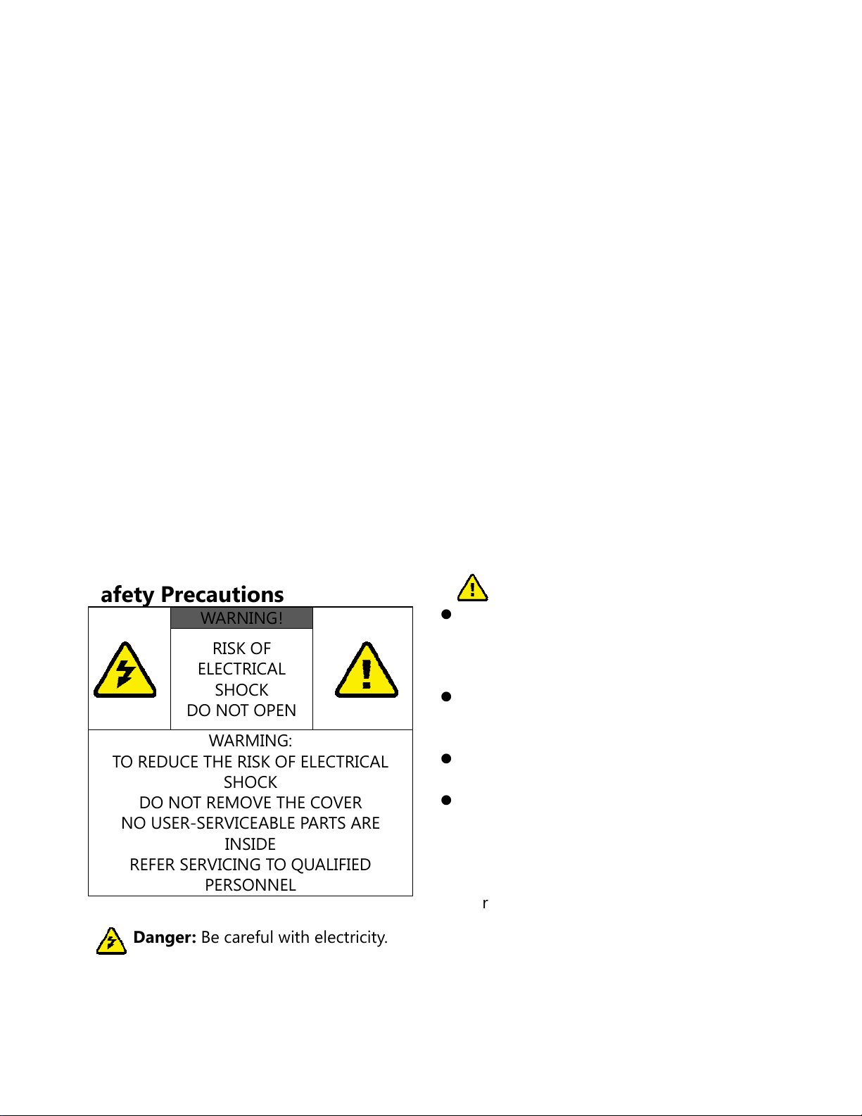
Safety Precautions
Repair, product modification or
alteration have been performed by
unauthorized service personnel
Damages caused by accidents,
including but not limited to, lightning,
water, fire, or moisture
Use of an AC adapter not compatible
with the product and its voltage rating
The model number on the product has
been altered, deleted, removed or
made illegible.
ELECTRICAL
DO NOT OPEN
TO REDUCE THE RISK OF ELECTRICAL
DO NOT REMOVE THE COVER
NO USER-SERVICEABLE PARTS ARE
REFER SERVICING TO QUALIFIED
Danger: Be careful with electricity.
Power to the units must be switched
off before any work is undertaken,
WARNING!
RISK OF
SHOCK
WARMING:
SHOCK
INSIDE
PERSONNEL
such as any AV device connection or
TV connection.
Power outlet: To prevent electric
shock, make sure to use the
appropriate AC adapters as power
supply to the transmitter and the
receiver.
Power cord: Be sure the power cord is
routed so that it will not be stepped on
or pinched by heavy items.
Power overloading: Avoid
overloading electrical outlets or
extension cords which otherwise could
result in electric shock or fire.
Lightning: Disconnect the product
from the power source if it is left
unattended for a long period of time,
and to protect the product from
lightning.
Always disconnect the power cord
from the power outlet when you are
not using your Full HD Video wireless
kit. This reduces the risk of electric
shocks or fire.
Warning
This product should not be exposed to
dripping or splashing. No object filled
with liquids, such as vases, should be
placed on the product.
Object Entry: To avoid electric shock,
never stick anything in the slots on the
case or remove the cover.
Place receiver/transmitter on a flat,
hard and stable surface
Ventilation: Do not block the
ventilation slots on the
receiver/transmitter or place any heavy
object on the top cover.
Blocking the air flow could damage the
receiver. Arrange components so that
air can flow freely around the receiver.
Ensure that there is adequate
ventilation if the receiver is placed in a
stand.
Put the receiver/transmitter in a
2

g
property ventilated area, away from
direct sunlight or any source of heat.
Water Exposure: To reduce the risk of
fire or electric shock, do not expose
the receiver/transmitter to rain or
moisture.
This is indoor solution.
Our company has the right to
modify this document without any
notice.
DECLARATION OF CONFORMITY
This device complies with Part 15 of the
FCC Rules. Operation is subject to the
following two conditions:
(1) This device may not cause harmful
interference, and
(2) This device must accept any
interference received, including
interference that may cause undesired
operation.
EMI (Electro Magnetic Interference)
EN 55022 Information technology
equipment----
Radio disturbance characteristics--Limits and methods of measurement
EN 61000-3-2 Electromagnetic
compatibility (EMC)---
Part 3-2:Limits---Limits for harmonic
current emissions (equipment input
current up to and including 16 A per
phase)
EN 61000-3-3 Electromagnetic
compatibility (EMC)---
Part 3:Limits---Section 3: Limitation of
voltage changes, voltage fluctuations and
flicker in public low-voltage supply
systems, for equipment with rated current
≦16 A per phase and not subject to
conditional connection
EN 55024 Information technology
equipment----
Equipment---Immunity
characteristics---Limits and methods of
measurement
EN 301 489-1
Electromagnetic compatibility and Radio
spectrum Matters (ERM); Electro
Magnetic Compatibility (EMC) standard
for radio equipment and services;
EN 301 489-17
Electromagnetic compatibility and Radio
spectrum Matters (ERM); Electro
magnetic Compatibility(EMC) standard
for radio equipment;
Part 17: Specific conditions for 2,4 GHz
wideband transmission systems, 5GHz
high performance RLAN equipment and
5,8 GHz Broadband Transmitting Systems
EN 60065 Audio,video and similar
electronic apparatus—Safety
TRADEMARK INFORMATION
HDMI, the HDMI Logo and
High-Definition Multimedia
Interface are trademarks of HDMI
Licensin
LLC.
Special Notice
Never use this product nearby an
aircraft or medical facility. It can
cause interference or undesirable
effect on the operation result.
Use of this product in the following
locations may result in abnormal video
and audio output (noise, blocked
image... etc,).
This product has been tested and
manufactured to comply with each
country’s safety rules. However, there
is no guarantee that interference will
not occur in some installation scenario.
If the interference happens, increase
the distance between the transmitter
and receiver.
ZWD-2422 may interfere 5GHz
wireless devices, such as routers or
other wireless devices. Therefore, if
you have an 802.11n router, configure
it to the 2.4 GHz band rather than the
5GHz band.
Optimal range between ZWD-2422
transmitter and receiver is between 2
and 20 meters within line of sight.
Product installed in the walls
made of concrete.
Product is situated near the
refrigerator or metal fitment.
A cluttered room where the
wireless signals may be blocked
3

CAUTION of RF module on US
region
Any changes or modifications not
expressly approved by the grantee of
this device could void the user's
authority to operate the equipment.
This equipment must be installed and
operated in accordance with provided
instructions and the antenna(s) used
for this transmitter must be installed to
provide a separation distance of at
least 20 cm from all persons and must
not be co-located or operating in
conjunction with any other antenna or
transmitter. End-users and installers
must be provided with antenna
installation instructions and
transmitter operating conditions for
satisfying RF exposure compliance.
Outdoor operations in the 5150 ~
5250MHz, 5600~5650MHz band are
prohibited.
This device has no Ad-hoc capability
for 5250~5350MHz and
5470~5725MHz.
Outdoor operations in the
5470~5725MHz band are prohibited.
This device could not be used in the
5600~5650MHz.
The Device not operation in
5600~5650MHz.
Industry Canada regulatory
information Operation is subject to the
following two conditions: (1) this
device may not cause interference, and
(2) this device must accept any
interference, including interference
that may cause undesired operation of
the device.
The user is cautioned that this device
should be used only as specified
within this manual to meet RF
exposure requirements. Use of this
device in a manner inconsistent with
this manual could lead to excessive RF
exposure conditions.
The following statement must be
included with all versions of this
document supplied to an OEM or
integrator, but should not be
distributed to the end user.
This device is intended for OEM
integrators only.
Please See the full Grant of
Equipment document for other
restrictions.
This device must be operated
and used with a locally approved
access point.
The following regulatory and Safety
notices must be published in
documentation supplied to the end
user of the product or system
incorporating an adapter in
compliance with local regulations,
Host system must be labeled with
“Contains FCC ID: XXX-XXXXX”, FCC ID
displayed on label.
System Warning
FEDERAL COMMUNICATIONS COMMISSION
INTERFERENCE STATEMENT
This equipment has been tested and found
to comply with the limits for a Class B digital
device, pursuant to Part 15 of the FCC Rules.
These limits are designed to provide
reasonable protection against harmful
interference in a residential installation. This
equipment generates, uses and can radiate
radio frequency energy and, if not installed
and used in accordance with the instructions,
may cause harmful interference to radio
communications. However, there is no
guarantee that interference will not occur in
a particular installation. If this equipment
does cause harmful interference to radio or
television reception, which can be
determined by turning the equipment off
and on, the user is encouraged to try to
correct the interference by one or more of
the following measures:
Reorient or relocate the receiving
antenna.
Increase the separation between the
equipment and receiver.
Connect the equipment into an outlet
on a circuit different from that to
which the receiver is connected.
Consult the dealer or an experienced
radio/TV technician for help.
4

CAUTION of System on US
region
Any changes or modifications not
expressly approved by the grantee of
this device could void the user's
authority to operate the equipment.
This equipment must be installed and
operated in accordance with provided
instructions and the antenna(s) used
for this transmitter must be installed to
provide a separation distance of at
least 20 cm from all persons and must
not be co-located or operating in
conjunction with any other antenna or
transmitter. End-users and installers
must be provided with antenna
installation instructions and
transmitter operating conditions for
satisfying RF exposure compliance.
Outdoor operations in the
5150~5250MHz, 5600~5650MHz band
are prohibited.
This device has no Ad-hoc capability
for 5250~5350MHz and
5470~5725MHz.
Outdoor operations in the
5470~5725MHz band are prohibited.
This device could not be used in the
5600~5650MHz.
The device not operation in
5600~5650MHz.
CAUTION of System on Canada
Industry Canada regulatory
interference,
interference, including
interference that may cause
undesired operation of the
device.
region
information Operation is subject to the
following two conditions:
1. This device may not cause
2. This device must accept any
The user is cautioned that this device
should be used only as specified
within this manual to meet RF
exposure requirements. Use of this
device in a manner inconsistent with
this manual could lead to excessive RF
exposure conditions.
5

CAUTION of System on US region
A voluntary WISPA sponsored database has been developed that allows operators and
installers to register the location information of the UNII devices operating outdoors in the
5470 – 5725 MHz band within 35 km of any TDWR location (see
http://www.spectrumbridge.com/udia/home.aspx). This database may be used by
government agencies in order to expedite resolution of any interference to TDWRs.
Any installation of either a master or a client device within 35 km of a TDWR location
shall be separated by at least 30 MHz (center-to-center) from the TDWR operating
frequency (as shown in the below table), and
Procedures for the installers and the operators on how to register the devices in the
industry-sponsored database with the appropriate information regarding the location
and operation of the device and installer information is included.
6

STATE CITY LONGITU
DE
LATITUDE FREQUENC
Y
TERRAIN
ELEVATION
(MSL) [ft]
TERRAIN [ft]
AZ PHOENIX W 112 09 46 N 33 25 14 5610 MHz 1024 64
CO DENVER W 104 31 35 N 39 43 39 5615 MHz 5643 64
FL FT LAUDERDALE W 080 20 39 N 26 08 36 5645 MHz 7 113
FL MIAMI W 080 29 28 N 25 45 27 5605 MHz 10 113
FL ORLANDO W 081 19 33 N 28 20 37 5640 MHz 72 97
FL TAMPA W 082 31 04 N 27 51 35 5620 MHz 14 80
FL WEST PALM BEACH W 080 16 23 N 26 41 17 5615 MHz 20 113
GA ATLANTA W 084 15 44 N 33 38 48 5615 MHz 962 113
IL MCCOOK W 087 51 31 N 41 47 50 5615 MHz 646 97
IL CRESTWOOD W 087 43 47 N 41 39 05 5645 MHz 663 113
IN INDIANAPOLIS W 086 26 08 N 39 38 14 5605 MHz 751 97
KS WICHITA W 097 26 13 N 37 30 26 5603 MHz 1270 80
KY COVINGTON
CINCINNATI
KY LOUISVILLE W 085 36 38 N 38 02 45 5646 MHz 617 113
LA NEW ORLEANS W 090 24 11 N 30 01 18 5645 MHz 2 97
MA BOSTON W 070 56 01 N 42 09 30 5610 MHz 151 113
MD BRANDYWINE W 076 50 42 N 38 41 43 5635 MHz 233 113
MD BENFIELD W 076 37 48 N 39 05 23 5645 MHz 184 113
MD CLINTON W 076 57 43 N 38 45 32 5615 MHz 249 97
MI DETROIT W 083 30 54 N 42 06 40 5615 MHz 656 113
MN MINNEAPOLIS W 092 55 58 N 44 52 17 5610 MHz 1040 80
MO KANSAS CITY W 094 44 31 N 39 29 55 5605 MHz 1040 64
MO SAINT LOUIS W 090 29 21 N 38 48 20 5610 MHz 551 97
MS DESOTO COUNTY W 089 59 33 N 34 53 45 5610 MHz 371 113
NC CHARLOTTE W 080 53 06 N 35 20 14 5608 MHz 757 113
NC RALEIGH DURHAM W 078 41 50 N 36 00 07 5647 MHz 400 113
NJ WOODBRIDGE W 074 16 13 N 40 35 37 5620 MHz 19 113
NJ PENNSAUKEN W 075 04 12 N 39 56 57 5610 MHz 39 113
NV LAS VEGAS W 115 00 26 N 36 08 37 5645 MHz 1995 64
NY FLOYD BENNETT FIELD W 073 52 49 N 40 35 20 5647 MHz 8 97
OH DAYTON W 084 07 23 N 40 01 19 5640 MHz 922 97
OH CLEVELAND W 082 00 28 N 41 17 23 5645 MHz 817 113
OH COLUMBUS W 082 42 55 N 40 00 20 5605 MHz 1037 113
OK AERO. CTR TDWR #1 W 097 37 31 N 35 24 19 5610 MHz 1285 80
OK AERO. CTR TDWR #2 W 097 37 43 N 35 23 34 5620 MHz 1293 97
OK TULSA W 095 49 34 N 36 04 14 5605 MHz 712 113
OK OKLAHOMA CITY W 097 30 36 N 35 16 34 5603 MHz 1195 64
PA HANOVER W 080 29 10 N 40 30 05 5615 MHz 1266 113
PR SAN JUAN W 066 10 46 N 18 28 26 5610 MHz 59 113
TN NASHVILLE W 086 39 42 N 35 58 47 5605 MHz 722 97
TX HOUSTON
INTERCONTL
TX PEARLAND W 095 14 30 N 29 30 59 5645 MHz 36 80
TX DALLAS LOVE FIELD W 096 58 06 N 32 55 33 5608 MHz 541 80
TX LEWISVILLE DFW W 096 55 05 N 33 03 53 5640 MHz 554 31
UT SALT LAKE CITY W 111 55 47 N 40 58 02 5610 MHz 4219 80
VA LEESBURG W 077 31 46 N 39 05 02 5605 MHz 361 113
WI MILWAUKEE W 088 02 47 N 42 49 10 5603 MHz 820 113
W 084 34 48 N 38 53 53 5610 MHz 942 97
W 095 34 01 N 30 03 54 5605 MHz 154 97
ANTENNA
HEIGHT
ABOVE
3
2. Introduction
ZWD-2422T and ZWD-2422R wireless HD
audio/video transmission solution allows
users to place their HDTV set or projector
where you want, free of the constraint of
cables. Just connect your HDTV to the
ZWD-2422R (receiver) with an HDMI cable,
and connect your AV equipment (Blu-ray
players, HD set-up boxes, game consoles or
HD media players and streamers) to the
ZWD-2422T (transmitter) Besides HDTVs,
any display with an HDMI input, such as LCD
and plasma monitors, are compatible with
the ZWD-2422R.
This setup doesn’t clutter your media and
allows the AV equipment to be hidden in the
cabinet behind your seating area. This
solution delivers uncompressed 1080p full
HD video and audio content to your existing
HDTV set wirelessly. It operates the
transmission in 4.9 GHz~ 5.9 GHz
frequencies and it can adjust its
communication frequency automatically in
case of interference from another RF system.
With built-in Omni-directional antennas, it
can transmit uncompressed video content to
20 meters (66 feet) LOS (Line of sight) with
no latency.
Both IR Sensor Extender Cable and IR Blaster
Extender Cable are included in the package
so users can point their remote control of
the AV source at the ZWD-2422R directly for
device operation.
Note:
Except North America, The wireless link
might require 80 seconds to connect
between transmitter and receiver, and
show video on the TV screen. Please be
patient and wait for a while.
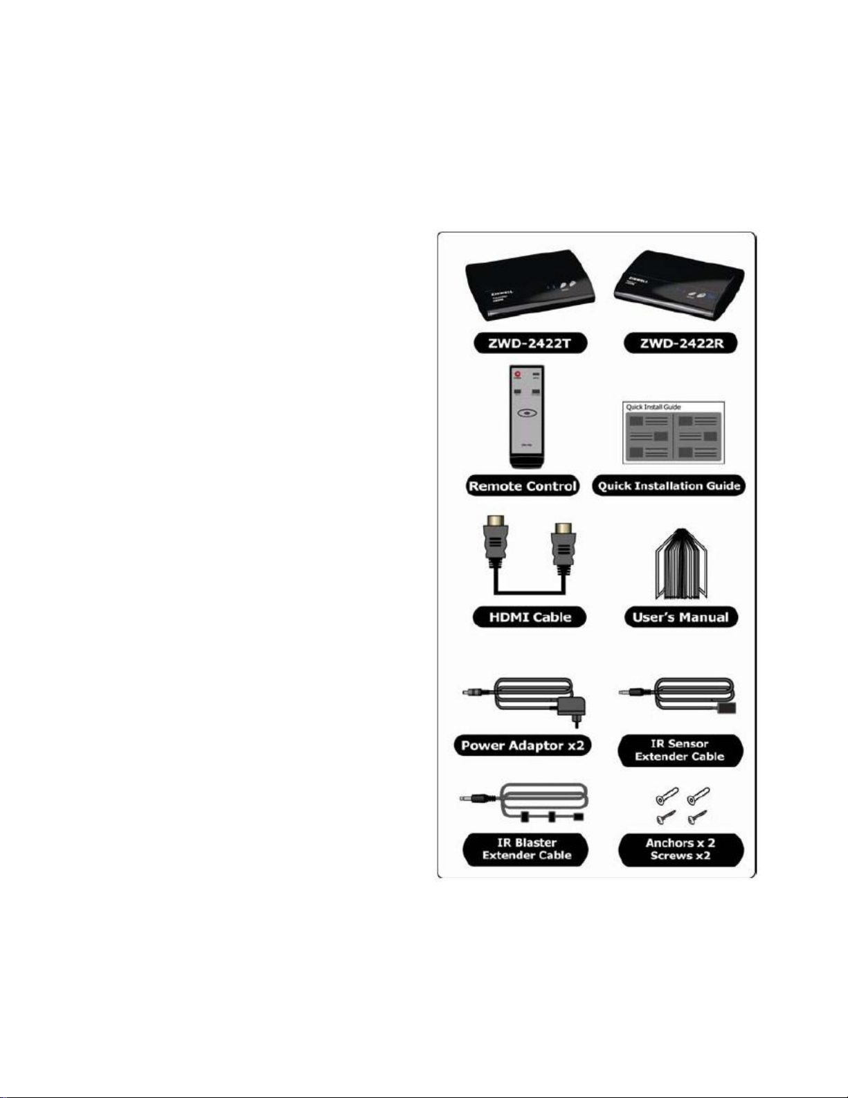
2.1 Packing Content
Please check whether the following items are
present in the package. If any items missed
or damaged, please call your dealer.
3

2.2 Overview
ZWD-2422T: Full HD Transmitter
A.
Front Panel Buttons and LEDs
Power Button with LED Indicator
Press to turn the transmitter on and off. The
indicator in the power button is lit in solid
blue when the power is on, and turns red in
standby mode.
Source Selection Button
Press to switch between the various inputs of
the transmitter. The one of two LED
indicators next to this button is lit in solid
blue to show current input you switch. Press
this button to cycle through connected
sources in sequence.
Note:
Make sure you have connected the
ZWD-2422R correctly to your HDTV set with
an HDMI cable, and have selected the
correct HDMI input on your TV.
If you have more than one pair of ZWD-2422,
each transmitter and receiver should be at
least 6.5 feet away from one another..
If both the transmitter and the receiver exist
in the same room, the suggested the
distance between the two is 6.5 feet
minimum.
Main Unit Back Panel
IR Blaster Extender Jack
Plug the IR Blaster Extender Cable into the IR
OUT jack at rear panel of the transmitter.
Attach the IR blaster to the device connected
to the ZWD-2422T. You can point your AV
equipment’s existing remote control at the
ZWD-2422R receiver (usually close to your
TV) to control connected Source device.
HDMI OUT
To use the “loop-through” feature, you can
place your 1
st
HDTV set close to the AV
equipment, and connect the ZWD-2422T
(transmitter) to that HDTV set via HDMI out,
and the AV equipment via HDMI in. Then,
you can enjoy the same digital content on
nd
your 2
HDTV set connected to the
ZWD-2422R (receiver), possibly in another
room.
HDMI IN
Connect Transmitter to High-definition
audio/video devices that have an HDMI port
using a provided HDMI cable.
DC IN
For connecting the ZWD-2422T power
adapter.
Note:
The ZWD-2422T transmitter can be
connected two audio/video devices running
on HDMI cable, plus looping through the
signals to the HDTV set via the HDMI OUT
port at the same time. Only one AV source
connected to the ZWD-2422T can be
selected and displayed on either the HDTV
also connected to the ZWD-2422T, or on a
2nd HDTV possibly in a different room, once
the transmitter is paired successfully with
receiver connected to the 2nd HDTV set.
4
 Loading...