

Zinwell ZPlus-B191-OD User Manual

Wireless LAN Device Series
WLAN Outdoor Bridge
ZPlus-B191-OD User’s Manual
Version. 1.02 (06.01.2004)

2
Notice
“This device complies with Part 15 of the FCC Rules. Operation is subject to the following two
conditions: (1) This device may not cause harmful interference, and (2) this device must accept
any interference received, including interference that may cause undesired operation.
Warning: Changes or modifications to this unit not expressly approved by the party responsible
for compliance could void the user authority to operate the equipment.
This device complies with Part 15 of the FCC Rules. Operation is subject to the following two
conditions: (1) This device may not cause harmful interference, and (2) this device must accept
any interference received, including interference that may cause undesired operation.
The user’s manual or instruction manual for an intentional or unintentional radiator shall caution
the user that changes or modifications not expressly approved by the party responsible for
compliance could void the user’s authority to operate the equipment.
NOTE: This equipment has been tested and found to comply with the limits for a Class B digital
device, pursuant to Part 15 of the FCC Rules. These limits are designed to provide reasonable
protection against harmful interfe rence in a residential installation. This equipment generates uses
and can radiate radio frequency energy and, if not installed and used in accordance with the
instructions, may cause harmful interference to radio communications.
However, there is no guarantee that interf erence will not occur in a particular installation. If this
equipment does cause harmful interference to radio or television reception, which can be
determined by turning the equipment off and on, the user is encouraged to try to correct the
interference by one or more of the following measures:
Reorient or relocate the receiving antenna.
Increase the separation between the equipment and receiver.
Connect the equipment into an outlet on a circuit different from that to which the receiver is
needed.
Consult the dealer or an experienced radio/TV technician for help.
Changes or modifications not expressly approved by the party responsible for compliance could
void the user‘s authority to operate the equipment.
The antenna(s) used for this transmitter must not be co-located or operating in conjunction with
any other antenna or transmitter
Shielded interface cables must be used in order to comply with emission limits.

This EUT is incompliance with SAR for general population /uncontrolled exposure limits in
ANSI/IEEE C95.1-1999 and had been tested in accordance with the measurement methods and
procedures specified in OET Bulletin 65 Supplement C
This device and its antenna(s) must not be co-located or operating in conjunction with any other
antenna or transmitter
CAUTION:
1. The antenna(s) used for this transmitter must be fixed-mounted on outdoor permanent
structures with a separation distance of at least 2 meters from all persons and must
not be co-located or operating in conjunction with any other antenna or
transmitter. Users and installers must be provided with antenna installation
instructions and transmitter operating conditions for satisfying RF exposure
compliance.
2. This Transmitter must not be co-located or operating in conjunction with any other
antenna or transmitter.
3. This equipment is only allowed to be professionally installed.
3

4
Contents
1 INTRODUCTION...................................................................................................................................................6
2 HARDWARE INSTALLATION............................................................................................................................ 7
2.1 PACKING LIST...................................................................................................................................................7
2.2 HARDWARE INSTALLATION...............................................................................................................................8
3 SOFTWARE CONFIGURATION.......................................................................................................................12
3.1 ENTER WEB CONFIGURATION PAGE................................................................................................................. 12
3.2 WLAN ACCESS POINT STA TUS .......................................................................................................................12
3.3 WIRELESS LAN SETTING ...............................................................................................................................14
3.3.1 Basic settings ............................................................................................................................................14
3.3.2 Wir eless Advanced Settings.......................................................................................................................17
3.3.3 Wireless Security setup..............................................................................................................................19
3.3.3.1 WEP Encryption Setting....................................................................................................................... 19
3.3.3.2 WEP Encryption with 802.1x Setting ...................................................................................................22
3.3.3.3 WPA Encryption Setting.......................................................................................................................23
3.3.4 Wireless Access Control............................................................................................................................24
3.3.5 Wireless Site Survey ..................................................................................................................................26
3.3.6 WDS Settings ............................................................................................................................................27
3.4 LAN INTERFACE SETUP..................................................................................................................................28
3.4.1 Using the Fixed IP....................................................................................................................................28
3.4.2 Using DHCP Client..................................................................................................................................29
3.4.3 Enable DHCP Server................................................................................................................................30
3.5 WLAN AP STATISTICS ...................................................................................................................................31
3.6 UPGRADE FIRMWARE .....................................................................................................................................32
3.7 SAVE/RELOAD SETTINGS ................................................................................................................................32
3.8 PASSWORD SETUP...........................................................................................................................................33
4 TECHNICAL SPECIFICATION ........................................................................................................................34
5 WIRELESS CONNECTION ARCHITECTURE..............................................................................................36
5.1 Infrastructure mo de..................................................................................................................................36
5.2 Ad-Hoc mode............................................................................................................................................36
5.3 WIRELESS AP FUNCTIONS ..............................................................................................................................37
5.3.1 Access Point Mode.................................................................................................................................... 37
5.3.2 Access Point Client Mode (ad-Hoc)..........................................................................................................38
5.3.3 Access Point Client Mode (Infrastructure) ...............................................................................................38
5.3.4 Wireless Repeater......................................................................................................................................39

5
5.3.5 WDS (Wireless Distribution System).........................................................................................................39
5.3.6 Wireless Bridge.........................................................................................................................................40
5.4 SELECTING AN APPROPRIA TE SITE...................................................................................................................41
5.5 POWER OVER ETHERNET ................................................................................................................................41

6
1 Introduction
ZINWELL ZPlus-B191-OD Wireless Outdoor Bridge is fully complying with 802.1 1b standard,
featuring with easy-to-install, and easy-to-manage, building-to-building and building to
multibuildings connection.
Our Outdoor Bridge is a flexible and cost-effective product which allows you to connect LANs
located in far distant buildings with data rate up to 11Mbps, ZPlus-B191-OD is an idea device to
replace the expensive lease lines, such as T1 line or fiber optics.
With Power over Ethernet function, ZPlus-B191-OD reduces installation expenses and
increases location options by using a single Ethernet cable to supply both data and power to
our Wireless Outdoor Bridge.
Applications
z Point-to-Point / Point-to-Multipoint Architecture
z Indoor/Outdoor Architecture
z Easy Installation
Features
z Complied With IEEE 802.11b 2.4GHz Standard
z Excelle nt Range with Power Build-in Amplifier
z Maximum S ensitivity of 89dBm at 11Mbps
z Data Security with 64/128- Bit WEP Encryption
2 Hardware Installation
This Chapter helps you to quickly and easily install the hardware.
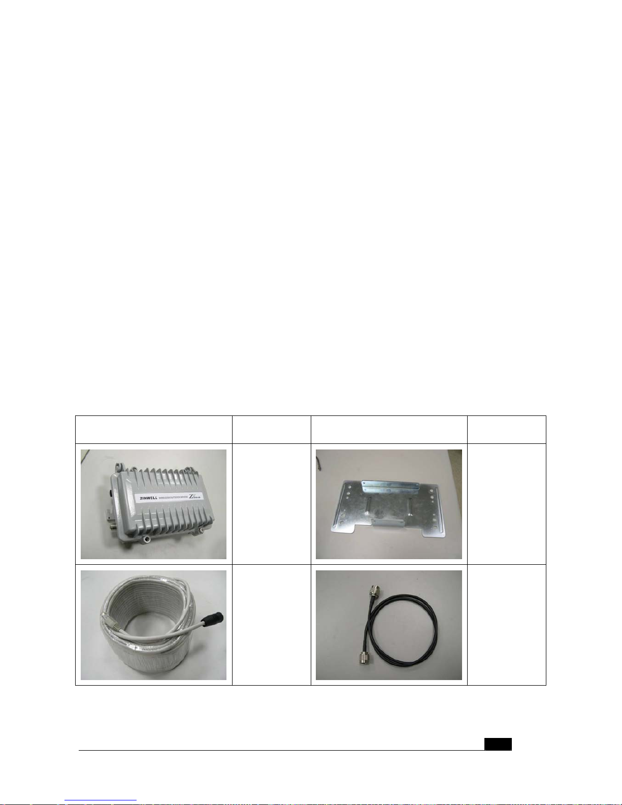
2.1 Packing List
Before you start install the Wireless Outdoor Bridge, you should check the following
packages you must have:
z Wireless Outdoor Bridge * 1
z Mounting Kits * 1
z Waterproof RJ-45 Cable (30M) * 1
z Waterproof RF Cable (1M) * 1
z Power Over Ethernet Kits * 1
z Grounding Wired * 1
z 2.5” /4” U bolts * 2 and Anchor * 4
z 6 / 9 dBi omni directional antenna * 1
Package Picture Package Name Package Picture Package Name
Wireless
Outdoor
Bridge
Mounting
Kits
Waterproof
RJ-45 Cable
Waterproof
RF Cable
7

Power Over
Ethernet Kits
Grounding
Wire
2.5” /4” U
bolts and
Anchor
6 / 9 dBi
omni
directional
antenna
2.2 Hardware Installation
After you check all of your packages are ready, you can start installing your wireless
outdoor bridge. You can mount to a pipe or a side of a building. The steps showed in
following:
1. You must mount the ZPlus-B191-OD into the bracket first.
Note: ALL the 4 screws had been tightly onto the Wireless Out door Bridge and
bracket
2. You can use the 2” inch or 4” inch U bolts to mount on the pipe.
The two U bolts must tightly mount and take care not to over-tighten
3. After check the ZPlus-B191-OD is mount well, you can connect two cables, Waterproof
RJ-45 network cable and RF cable, and the grounding wire.
The waterproof RF cable must tightly onto the Wireless Outdoor Bridge and another
side that link to the Antenna better to have the lightening protector
4. The waterproof RJ-45 cable also had been tightly onto the Wireless Outdoor Bridge and
another side that be plugged into PoE device.
8
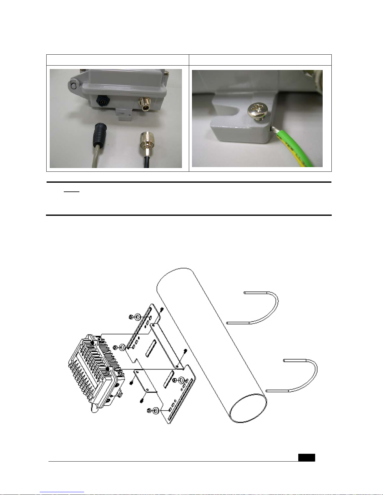
ZPlus-B191-OD Cable connection ZPlus-B191-OD grounding wire connection
Note:
DON’T plug the power cord into PoE device to power on the system before you
finish install the antenna and grounding wire to ensure the safety.
You can follow the figure to mount the ZPlus-B191-OD quickly.
9
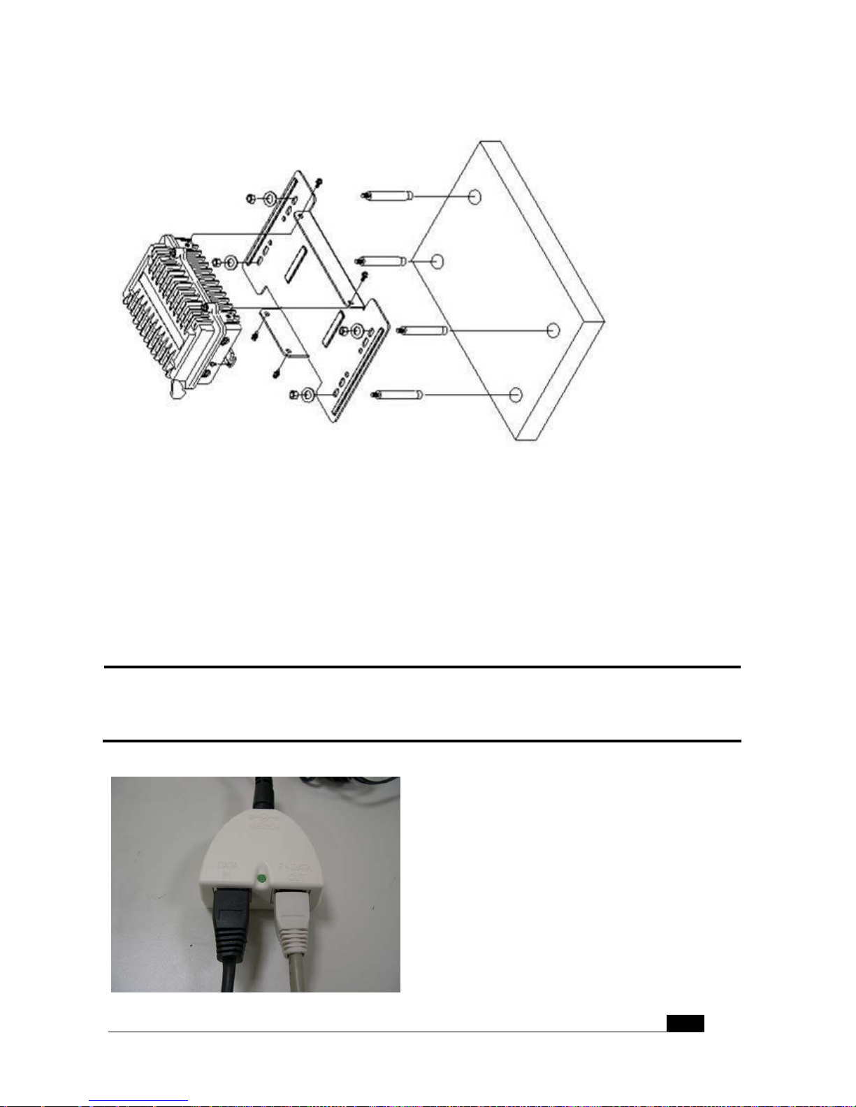
You can also mount the ZPlus-B191-OD on the wall to fit in your environment.
In the ZPlus-B191-OD indoor part installation, if the RJ-45 cable’s length is not enough for
you to link to your network device, you can extend the cable length, but you need to careful
the maximum length of the RJ-45 cable is 100M.
When you plug the RJ-45 cable into the PoE device, you should use the normal RJ-45
cable to plug into the “DATA IN” to connect to hub/switch or use the crosslink Rj-45 cable to
connect to user’s PC.
Then the waterproof RJ-45 cable must connect to the “P+DATA OUT” port.
Note:
Please careful not to plug inversely the two cables. This way maybe damages
the devices!
10
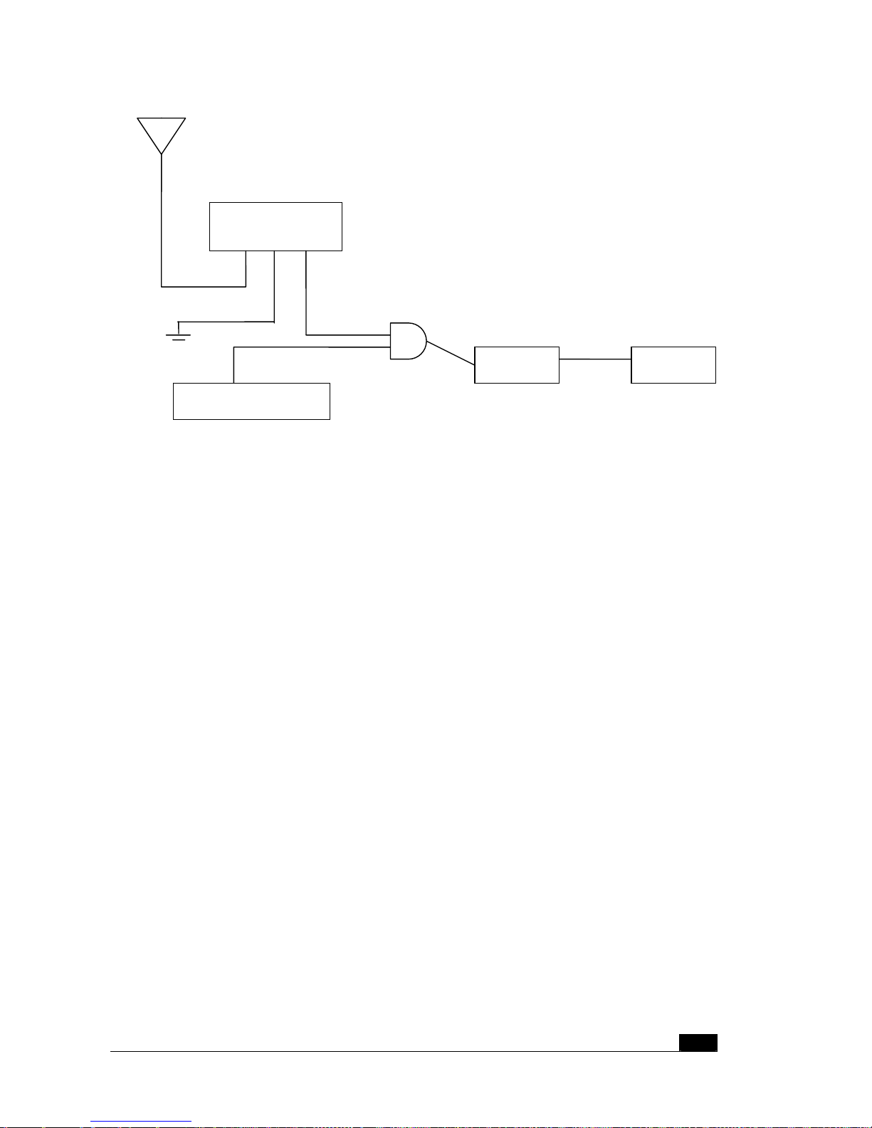
The simple composed figure shows in below for your reference.
11
Power injector
ZPlus-B191-OD
Antenna
Waterproof RF cable
W a terproof RJ-45 cable
Grounding wire
RJ-45 cable
Power supply
Power cord
HUB / SWITCH

12
3 Sof tware Configuration
3.1 Enter web configuration page
The default IP Address of ZPlus-B191-OD is 192.168.2.254 and Subnet Mask is
255.255.255.0.
You need to configure your PC’s TCP/IP setting on the same segment to access the AP.
For example:
• IP address 192.168.2.X (X must between 1 and 253 that is not used by another device)
• Subnet Mask 255.255.255.0 (same as the ZPlus-B191-OD AP)
After you had configured your PC’s TCP/IP setting, you may need to reboot your PC to finish
the network configuration when your OS ask you to do that such as Win98.
You can open a web browser and enter the IP address of the AP:
http://192.168.2.254
Then you can enter the AP’s web configuration page.
3.2 WLAN Access Point Status
The first page you can see the status of the AP, all item’s descriptions show in below table.
The AP status description:
System
Alias Name Show this AP device name.
Uptime System up time.
Firmware Version Show AP firmware version now.
Wireless Configuration
Mode Show the mode (AP or Client) using now.
SSID Show the SSID setting name now.
Channel Number Wireless channel using in this AP.
Encryption Encryption status
Associated Clients How many client connection now
BSSID Show the BSSID setting name now.
TCP/IP Configuration
Attain IP Protocol The IP setting mode
IP Address 192.168.2.254
Subnet Mask 255.255.255.0
Default Gateway 192.168.2.254
MAC Address
00:05:9e:80:01:a9

13
 Loading...