

Zinwell PWQ51N00 User Manual

802.11n+HomePlugAV
Embeddedantenna
LowPowerConsumption
PowerlineWirelessNExtender
PWQ‐5101
UserManual

Preface
This product is a wireless AP device with PowerLine Communication (PLC) capability. With
its newest 500Mbps PLC technologies (Homeplug AV), crossing-floor communication in a
concrete building, which has been a big problem of wireless networking, become very
reliable. Its cutting edge 802.11n wireless technology provides the highest wireless
throughput for devices in the same floors. Its embedded 1T1R MIMO antenna makes it the
easiest for wall installations.
This product is suitable for general users to install in their home/houses, while advanced
configuration through web-browser described in later chapters is suitable for the
experienced users who installs and manages the Powerline Wireless N Extender products
(hereafter referred to as the “device”). To use these chapters, you should have experience
working with the TCP/IP configuration and be familiar with the concepts and terminology of
wireless local area networks.
2

Important Safety Notes
This product is intended for connection to the AC power line. For installation instructions,
refer to the Installation section. The following precautions should be taken when using this
product.
Please read all instructions before installing and operating this product.
Please keep all instructions for later reference.
Please follow all warnings and instructions marked on the product.
For safety reason, when device is being powered on, this product should NOT be
installed in any electric socket which makes the surface with venting holes on
the product to face downward (facing the floor).
Unplug the Powerline device from the wall outlet before cleaning. Use a dry cloth
for cleaning. DO NOT use liquid cleaners or aerosol cleaners.
DO NOT operates this product near water.
This product should never be placed near or over a radiator, or heat register.
This product relies on the building’s electrical installation for short-circuit (over current)
protection.
DO NOT allow anything to rest on the product interconnect plug. DO NOT locates this
product where people may walk on the cords.
Because this product sends data over the power line, it is recommended that you plug
directly into a power outlet. Do not plug the device into a UPS or power strip with surge
protection. The product has its own power filter for protection against surges.
Only a qualified technician should service this product. Opening or removing covers
may result in exposure to dangerous voltage points or other risks.
Unplug the product from the wall outlet and refer the product to qualified service
personnel for the following conditions:
When the interconnect cords are damaged or frayed.
If liquid has been spilled into the product.
If the product has been exposed to rain or water.
If the product does not operate normally when the operating instructions are
followed.
If the product exhibits a distinct change in performance.
3

TABLET of CONTENT
CH 1. PRODUCT OVERVIEW..............................................................................................6
Packing List....................................................................................................................................................... 6
Buttons and LEDs............................................................................................................................................. 6
CH 2. HARDWARE INSTALLATION...................................................................................9
Application 1 – Link to remote DSL via Powerline........................................................................................ 9
Application 2 – wireless AP + Ethernet switch ............................................................................................ 10
Application 3– multiple floor home networking........................................................................................... 10
Application 4– Powerline Ethernet switch ................................................................................................... 12
Application 5 – AP client adapter.................................................................................................................. 12
Fast Encryption by Buttons........................................................................................................................... 13
CH 3. ADVANCED SETTING – VIA WEB BROWSER......................................................16
Before Starting Configure.............................................................................................................................. 16
Operation Mode............................................................................................................................................... 16
Setup Wizard ................................................................................................................................................... 17
Internet Settings.............................................................................................................................................. 18
LAN Settings -------------------------------------------------------------------------------------------------------------------- 18
DHCP Clients-------------------------------------------------------------------------------------------------------------------- 20
Wireless Settings............................................................................................................................................ 20
Basic ------------------------------------------------------------------------------------------------------------------------------- 20
Advanced------------------------------------------------------------------------------------------------------------------------- 22
Security --------------------------------------------------------------------------------------------------------------------------- 23
WPS --------------------------------------------------------------------------------------------------------------------------------25
Station list------------------------------------------------------------------------------------------------------------------------ 26
Site Survey----------------------------------------------------------------------------------------------------------------------- 26
MAC Filter ------------------------------------------------------------------------------------------------------------------------ 27
4

Administration................................................................................................................................................. 27
Management--------------------------------------------------------------------------------------------------------------------- 27
Upgrade firmware-------------------------------------------------------------------------------------------------------------- 28
Settings management -------------------------------------------------------------------------------------------------------- 29
Status------------------------------------------------------------------------------------------------------------------------------ 29
Statistics-------------------------------------------------------------------------------------------------------------------------- 30
System log ----------------------------------------------------------------------------------------------------------------------- 30
FEDERAL COMMUNICATIONS COMMISSION INTERFERENCE STATEMENT------------------------------ 31
CH 4 ENHANCE PLC PERFORMANCE DURING INSTALLATION..................................33
AC outlets connection.................................................................................................................................... 33
Connection via power strip............................................................................................................................ 35
Electrical interference .................................................................................................................................... 35
Electrical wiring............................................................................................................................................... 35
CH 5 SPECIFICATION .......................................................................................................36
5
Ch 1. Product Overview
Packing List
Before starting the installation of the device, please make sure the package contains the following
items:
Single package Combo package
Device
Accessories
PowerlineWireless
RJ-45 Cable x 1 RJ-45 Cable x2
NExtender
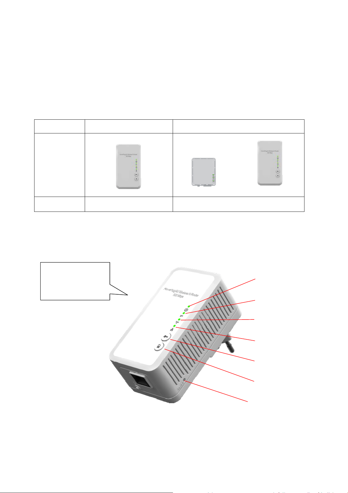
Buttons and LEDs
Front View
1T1Rantennasare
embeddedintothe
device
Powerline
EthernetBridge
PowerlineWireless
NExtender
PowerLED
PLCLED
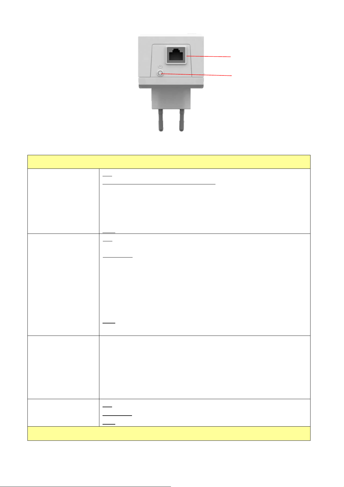
Bottom View
WLANLINK/ACTLED
EthernetLNK/ACTLED
WPS
GROUP
RESET
button
6
Power LED
Green
PLC LED
Green
LANport
PowerOn/Off
LED
ON
: Power on and ready.
BLINKING: ( 0.5 sec ON / 0.5 sec OFF )
1. During Group pairing procedure. In this procedure, the device
joining or being joined into same logical network will continue 2
minutes’ blinking, until the procedure succeeds or is canceled). To
enter or cancel Group pairing procedure, just press the GROUP
button 2~3 sec.
OFF
: Power off.
ON
: Powerline Link detected but no powerline traffic.
BLINKING
1. Fast blinking (0.06 s ON/ 0.06 s OFF): Powerline data rate higher
than 80Mbps.
2. Normal blinking (0.2 s ON/ 0.2 s OFF) Powerline data rate between
40Mbps to 80Mbps.
3. Slow blinking (1 s ON/ 1 s OFF): Powerline data rate slower than
40Mbps.
OFF
: Powerline Link not detected (either other devices in same network
:
WLAN LED
Green + Red
Ethernet LNK/ACT
LED
is too far to communicate or it is alone in its logical network).
Steady Green: Wi-Fi active under security protection
Flash Green: Wi-Fi transmits packets under security protection,
Steady Red: Wi-Fi active under NO security protection,
Flash Red: Wi-Fi transmits packets under NO security protection,
BLINKING Green (0.5 sec ON / 0.5 sec OFF): WPS negotiation
OFF:Wi-Fi off
ON
: Ethernet Link Detected.
BLINKING
OFF
: Ethernet traffic detected.
: No Ethernet Link detected.
Buttons
7

WPS
Press it to enable PBC (Press Button Configuration) for WPS authentication.
GROUP
Power On/Off
RESET button
(inside the needle
pin hole)
Press 1 to 3 seconds ( until the Power LED blinking ) and release button:
this
will enter Group pairing procedure. In this procedure, the device starts
joining into a logical network of other device or announcing its network group
name for other devices to join. This maximum two-minute procedure
automatically ends when it succeeds or is manually stopped. Press this
button 2 to 3 seconds will manually stop the procedure.
Press 10 seconds (until Power LED blink once and PLC LED off):
clear the
current and randomly generate a new network group name.
Push to turn on and off the power of PWQ-5101
Press the button when the device is powered on (not standby) to complete
following functions:
Pushing 1 second and release :
will make both PLC and Wi-Fi FW settings
back to factory default.
NOTE
: Every new PLC devices’ factory default PLC network group name is
HomePlugAV. During trouble shooting the powerline network group
assignment, doing this to every PLC devices will make each device return to
default network group, thus ensure their mutual communicability.
8
Ch 2. Hardware Installation
Once you check everything from the package, you can start to install the device. All wireless de vices
which want to connect this AP wirelessly need to search and connect the SSID of this device:
PWQ-5101 (factory default is no wireless security setting)
Please see the following application diagrams for different application connections of this device.
Application 1 – Link to remote DSL via Powerline
Via Powerline technology, the Powerline Wireless N Extender can access DSL modem at other
floors for internet accesses. Note that this needs another Powerline to Ethernet Bridge device at
other floor, so that connection between Powerline to Ethernet Bridge and Powerline to Ethernet
Bridge can be done through the embedded PLC technology.
9
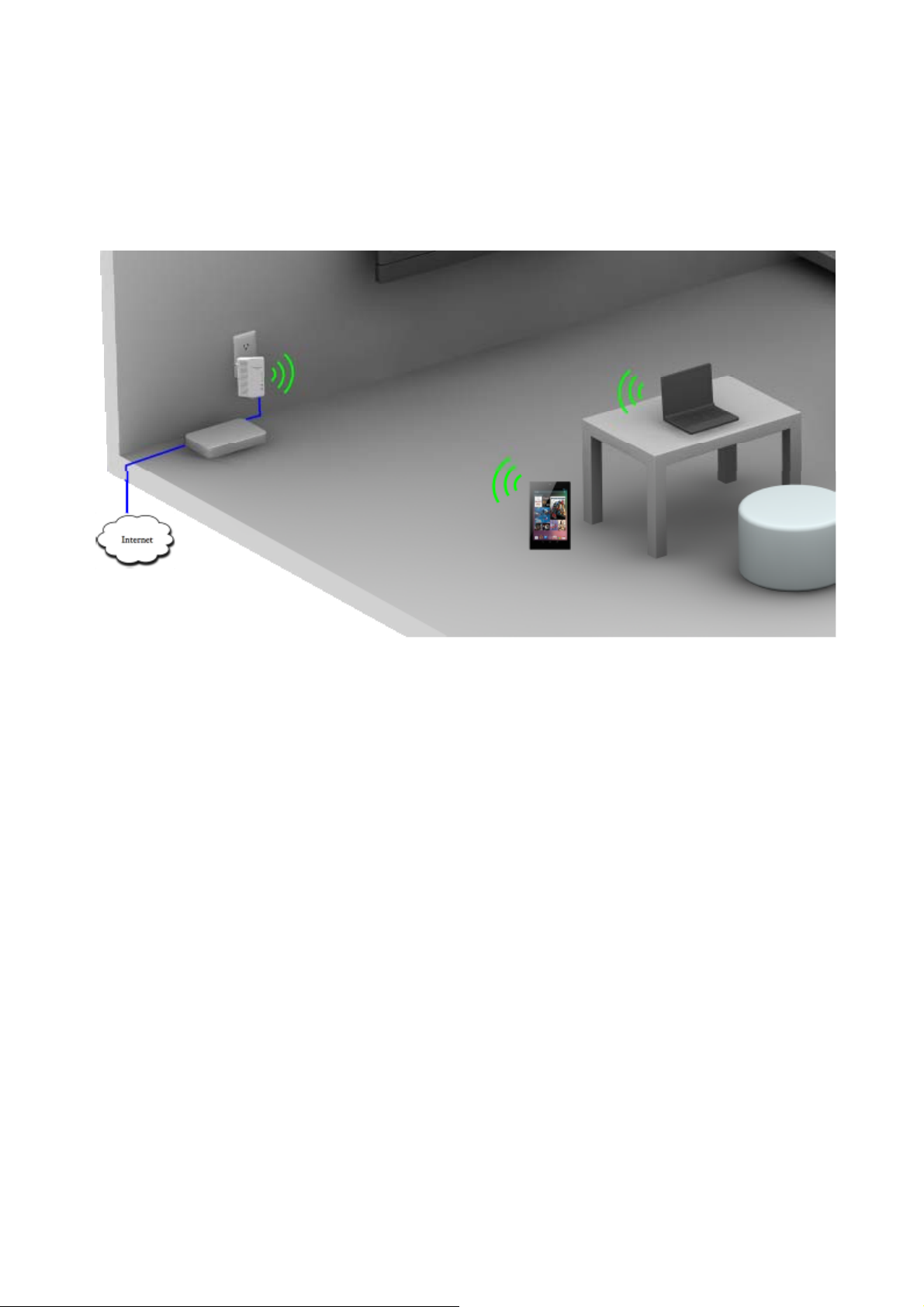
Application 2 – wireless AP + Ethernet switch
The Powerline Wireless N Extender can be a central 802.11n Access point and Ethernet switch
hub to link all WLAN devices and Ethernet devices.
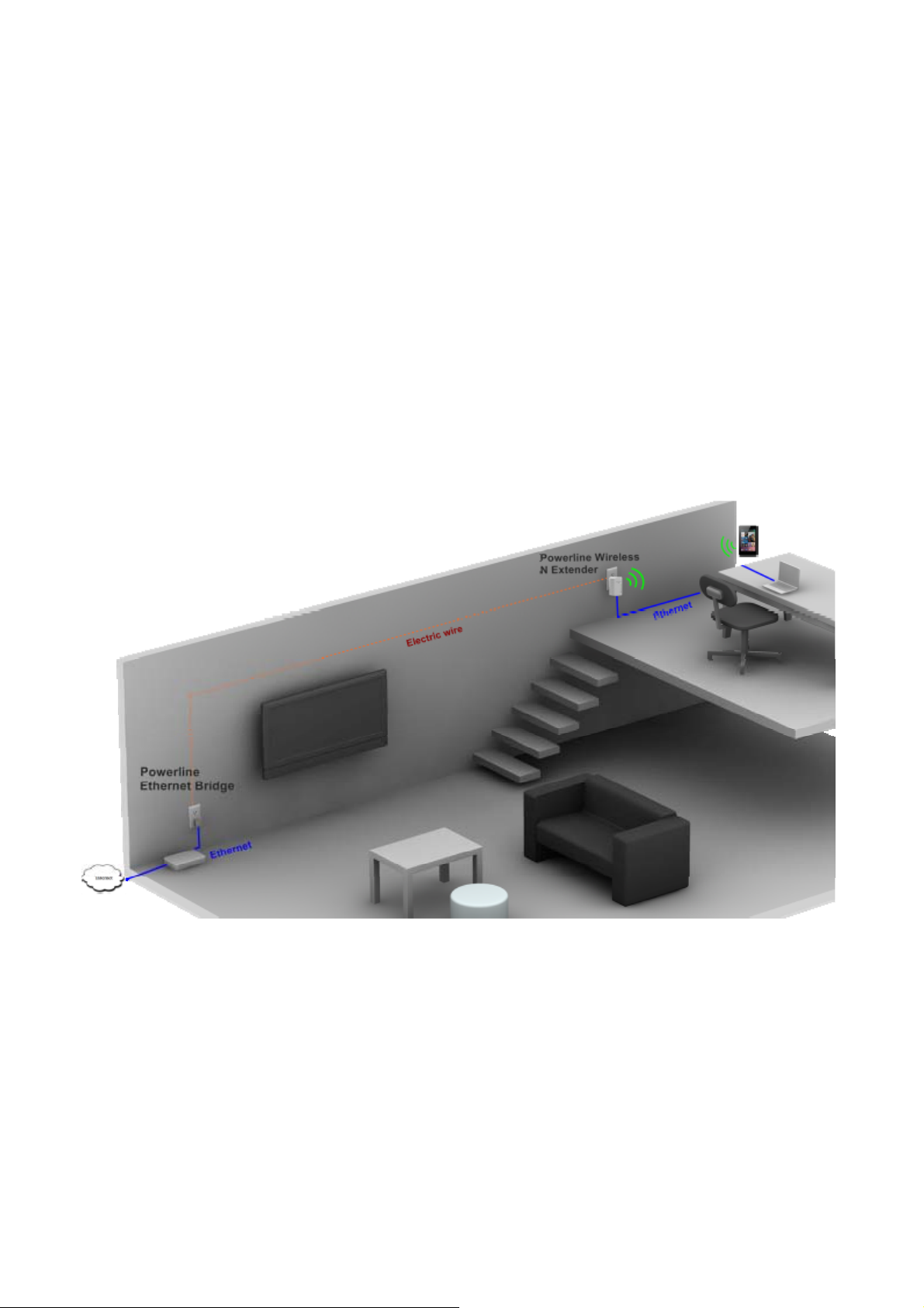
Application 3– multiple floor home networking
When WLAN signal is not good to penetrate concrete floors, use Powerline technology afforded by
the Powerline Wireless N Extender to extend home networking range to upper (other) floors. While
on the same floor, the WLAN function can be used for IP devices or PC/NB to access internet.
Please see the diagram below and please note that this needs Powerline to Ethernet Bridge
devices for users at the other floor to access network resources via the Powerline communication.
10

11
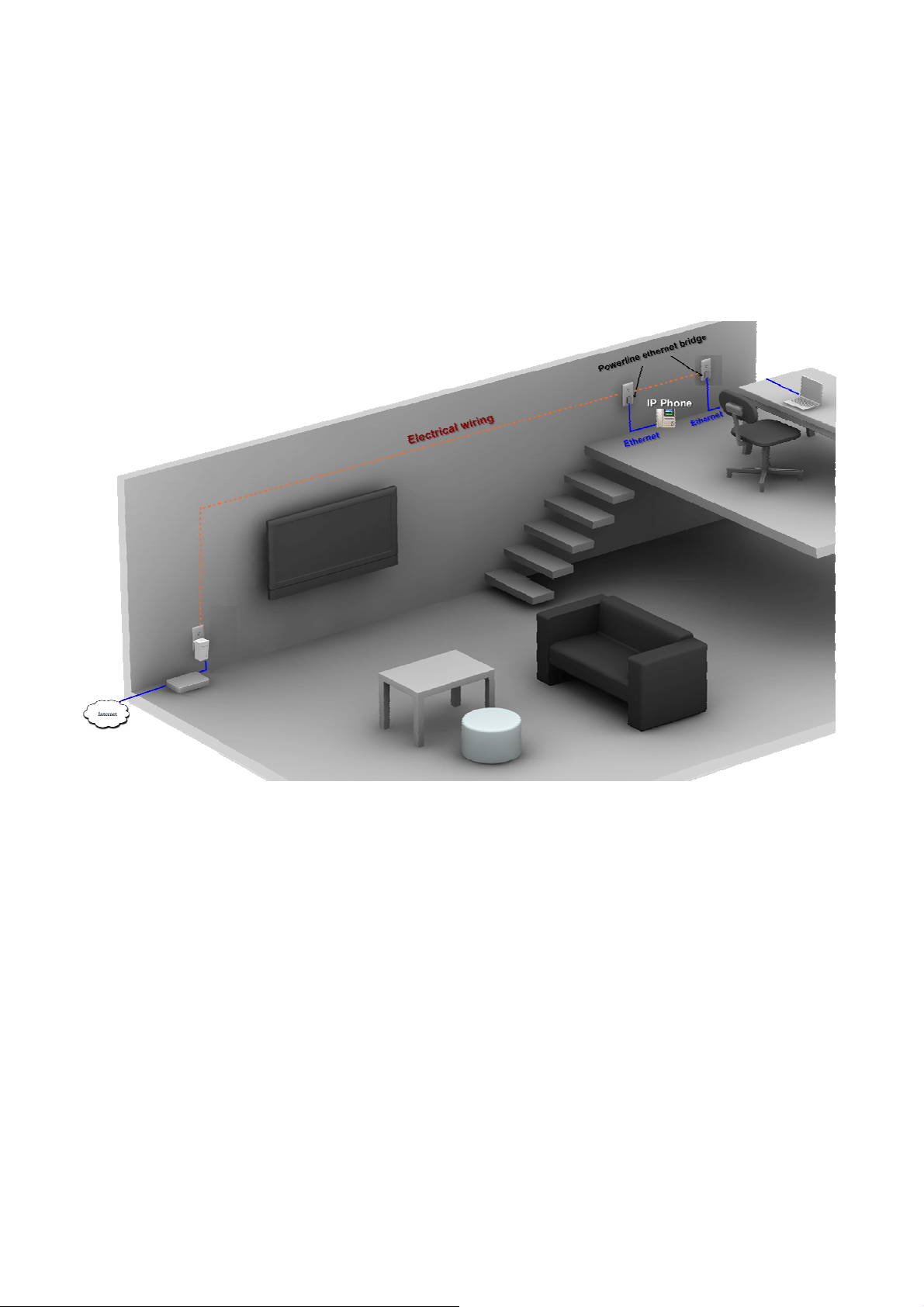
Application 4– Powerline Ethernet switch
By pushing the WLAN ON/OFF button, the wireless function of this device can be turned
ON or OFF. In this case, HomePlug AV Wireless N Extender acts as Powerline to
Ethernet switch, which, when used together with a remote Powerline Ethernet Bridge,
enables two remote Ethernet devices (ex. PC, Notebook, or VIOP) on different floors or
locations at home to communicate via the embedded Powerline technology.
Application 5 – AP client adapter
This device can act as wireless client adapter for a PC host (see application diagram below).
To activate this function, visit the operation mode web page of the device and enable this
mode through a web browser on your PC. Please see later chapters for detail description of
this procedure.
12
 Loading...