

Page 1
SRE 25 E
3
2
6
5
FIN
4
>
u
1
=
MANUEL D'UTILISATION
GEBRAUCHSANWEISUNG
BRUGSANVISNING
INSTRUCCIONES DE USO
KÄYTTÖOHJE
OPERATING MANUAL
ISTRUZIONI D’USO
BRUKSANVISNING
GEBRUIKSAANWIJZING
BRUKSANVISNING
2
14
26
38
50
62
74
86
98
110
Page 2

3
PAGE PLIANTE
2
6
5
FIN
5
4
>
u
FALTBLATT
FOLDEUDSIDE
HOJA DESPLEGABLE
AUKI TAITETTU SIVU
FOLD-OUT PAGE
PIEGHEVOLE
UTBRETTSIDE
1
=
E E E E E E E E E E E E E E E E E E E E E
a
-
UITVOUWBLAD
UTVIKNINGSSIDA
EMC
a
-
LV
Page 3

Dear Sir, Madam,
Congratulations with your purchase of a portable domestic heater. You have
purchased a quality product, which will serve you for many years to come. This,
of course, provided you use the heater correctly. Please read these Directions
for Use first, to ensure maximum lifetime for your heater.
Your heater comes with a 48-month manufacturer’s warranty on all defects in
materials or workmanship.
We wish you a warm and comfortable time with your heater.
Yours sincerely,
PVG International b.v.
Customer Service Department
1 READ THE DIRECTIONS FOR USE FIRST.
2 IN CASE OF ANY DOUBT
3 BEFORE YOU START READING, FOLD OUT THE LAST PAGE. E E E E E E E E E E
, CONT
ACT YOUR DEALER.
4
62
Page 4

GENERAL DIRECTIONS FOR USE
Below you will find the main steps to be taken for
using your heater. For more details, please refer to
the MANUAL (pages 65 ff.).
Remove all packaging materials (refer to Section A, Fig. A).
1
Fill the removable tank 6 (refer to Section B, Fig. C).
2
Insert the plug into the wall-socket.
3
Ignite the heater using the key
4
If required, change the temperature using the adjustment keys
5
(refer to Section E).
L (refer to Section D).
MAIN COMPONENTS
Front plate
A
G
rid
B
Base plate
C
Lid for removable
4
tank
Operation panel
E
Removable tank
F
Fuel gauge
G
removable tank
Vent filter
H
Thermostat
I
Switch off the heater by pressing the key L.
6
• The first time you ignite your heater it will smell
like ’new’ for a short time.
• Store your fuel in a cool and dark place.
• Fuel has a limited shelf life. Start every heating
season with renewed fuel.
• The right quality of fuel will be assured, when
you use Zibro Extra or Zibro Kristal for your
heater
.
• If you change to another brand and/or type of
parrafin oil, you must first finish up all the
r
emaining fuel in the heater.
Plug + cord
J
Information display
K
L
M
N
O
P
Q
R
key
Childproof lock
Adjustment keys
(time and
temperature)
Timer
POWER lamp
TIMER lamp
Air quality contr
system
S
VE key
SA
S
ol
E E E E E E E E E E E E E E E E E E E E E E E
4
63
Page 5
Only the use of the
correct fuel will ensure
safe, efficient, and
comfortable use of your
heater.
WHAT YOU NEED TO KNOW IN ADVANCE
ALWAYS MAKE SURE THAT THERE IS SUFFICIENT VENTILATION
This heater is equipped with an air quality control system R. When there is
insufficient ventilation in the room or when the heater is being used in a room
w
hich is too small, the heater will shut off automatically. For comfortable and safe
heating ensure that there is sufficient ventilation.
Note: To avoid unexpected shut off, we recommend to put a door or window ajar
when the heater is operating.
For each model the minimum size of space is specified in which you can use the
heater safely, without additional ventilation
room is smaller than the specified space, always put a window or door slightly ajar
(± 2.5 cm). We also recommend doing this in highly insulated or draught-free
rooms and/or at altitudes above 1,500 metres. Do not use your heater in cellars or
other underground areas.
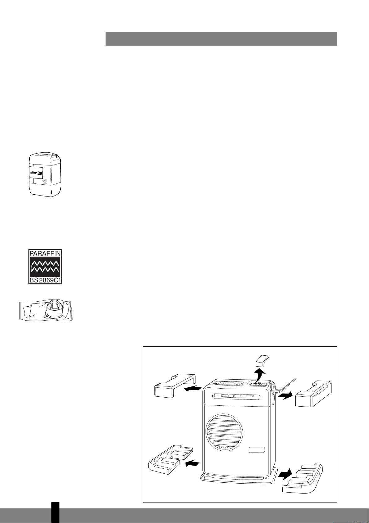
THE RIGHT FUEL
Only use Class C1 paraffin fuel in accordance with BS2869; Part 2, or equivalent.
Your heater has been designed for use with high-quality water-free pure paraffin
oil, such as Zibro Extra or Zibro Kristal. Only fuels of this kind will ensure clean and
proper burning. Lower quality fuel may result in:
E increased possibility of malfunctioning
E incomplete burning
E reduced heater lifetime
E smoke and/or smells
E deposits on the grid or mantle
(refer to Section O). If a particular
This transportation cap
is packed separately in
the box. Only this cap
ensures trouble-free
transportation of the
heater after use.
Store it well!
Using the right fuel is therefore essential for safe, efficient, and comfortable use
of your heater.
Always refer to your local dealer for the right fuel for your heater.
A
4
64
Page 6

MANUAL
54321
65432
1
A INSTALLING THE HEATER
Carefully remove your heater from the box and check the contents.
I
n addition to the heater you also need to have:
E a manual fuel pump
E a transportation cap
E these directions for use
Keep the box and the packaging materials (Fig. A) for storage and/or
transportation.
E E E E E E
Open the lid of the removable tank
Fill the removable tank as indicated in
The floor should be firm and completely level. Reposition the heater, when it
is not level. Do not try to correct the situation by placing books or other
goods under the heater.
Insert the plug J into the wall-socket (230 Volts - AC / 50 Hz) and set the
correct time using the adjustment keys
Your heater is now ready for use.
B
D and remove the piece of cardboard.
Section B.
N (refer to Section C).
B FILLING FUEL
Do not fill the removable tank in the living room, but in a more suitable place
(there can always be some spillage). Follow the procedure below:
Make sure that the heater is switched off.
Open the lid
Note: Some drops may leak from the tank. Put down the removable tank
(cap pointing upwards) and screw off the fuel cap.
C
Take the manual fuel pump and insert the smooth, most rigid tube into the
jerrycan. Make sure that it is in a higher position than the removable tank
(Fig. C). Insert the ribbed hose into the opening of the removable tank.
Lock the switch button on top of the pump (turn clockwise).
Squeeze the pump a few times, until fuel star
tank. As soon as this happens, there is no need to press any longer.
4 and lift the removable tank 6 out of the heater (Fig. B).
ts flowing into the removable
4
65
Page 7

8
7
6
D
C
heck the removable tank fuel gauge
filling by loosening the switch button on top of the pump (turn anti-clockwise), once the gauge indicates that the tank is full. Never overfill the tank,
especially not when the fuel is very cold (fuel expands when it heats up).
7 w
hile filling the tank (Fig. D). Stop
empty full
E: When the 4-digit stops
blinking, the setting has
been locked to the
indicated value.
L
et the remaining fuel in the pump flow back into the jerrycan and carefully
remove the pump. Carefully screw the fuel cap back on the tank. Clean off
any spilled fuel.
Check whether the fuel cap is straight and tightened properly. Reinstall the
removable tank in the heater (cap down). Close the lid.
C SETTING THE CLOCK
It is only possible to set the correct time, when the heater is connected to the
mains and not burning. Use the adjustment keys
either of the two keys to switch on the function (the 4-digit
Next, set the hours using the key on the left (
M
key on the right (
hold down the key, the value will continue going up, until you release the key
again. After approximately 10 seconds the 4-digit will stop blinking and the
setting will be locked. 5 minutes after switching off the heater, the information on
the display will disappear and the heater will automatically switch into the standby position.
min.). Press once to increase the value by one step. When you
N to set the time. First press
K will start blinking).
N
hour) and the minutes using the
F: The requir
temperature on the left,
the measured
temperature on the
right.
ed
When the heater has been unplugged (or after a power failure), the time needs
☞
to be set again.
D IGNITING THE HEATER
When used for the first time, a new heater may give out a smell for a short while.
You should therefore provide extra ventilation. Always ignite the heater with the
button L
Just press the button L to ignite the heater. The POWER lamp P will start
blinking, indicating that the ignition procedure has started. This will take a short
while. Once the heater is burning, the POWER lamp
information display
that these numbers refer to the temperatures (Fig. F). The actual room temperature
is indicated below ROOM, while the temperature setting is indicated below SET.
The latter can be changed with the adjustment keys
Prior to igniting the heater
. Never use matches or a cigarette lighter.
K will show two numbers. The light next to them indicates
, always check for sufficient fuel in the removable tank.
E SETTING THE REQUIRED TEMPERA
The temperature setting can only be adjusted, when the heater is burning. Use the
adjustment keys
switch on the function (the °C mark and 4-digit
the temperatur
N to adjust the temperature. First press either of the two keys to
e using the key on the right (
TURE
P will remain lit (red). The
(refer to Section E).
K will start blinking). Next, adjust
M
min.) to set the temperatur
e to a
4
66
Page 8

h
2
1
432
1
igher setting and the key on the left (
once to increase the value one step. After approximately 10 seconds the °C mark
and 4-digit will stop blinking and the setting will be locked (Fig. F).
The available temperature settings range from 6°C minimum to 28°C maximum.
When the heater has been unplugged (or after a power failure), the temperature
w
ill reset to the factory setting of 20°C.
N
h
our) to lower the temperature. Press
F USING THE TIMER
The timer allows you to switch on the heater automatically at a preset time.
In order to switch on the timer, the correct time must have been set
Section C)
and the heater should be off. Follow the procedure below:
(refer to
G: The TIMER indicator
light indicates that the
timer function has been
switched on.
☞
Press the button
The TIMER lamp
Use the adjustment keys
Use the key on the left (
M
min.) to set the minutes (interval of 5 minutes).
(
After approximately 10 seconds the 4-digit will show CLOCK again and the
TIMER lamp
activated (Fig. G).
The timer will ensure that the room will have been heated to approximately
the required temperature at the set time.
When you want to switch off the heater and ignite it again with the timer, all
you have to do is press the TIMER key
Press the button L once to clear the timer setting.
Q will light up, indicating that the timer function has been
L and then the TIMER key O immediately after that.
Q and the 4-digit K will start blinking.
N to set the time at which the heater must ignite.
N
hour) to set the hours and the key on the right
(refer to Section G).
G SWITCHING OFF THE HEATER
There are two ways to switch off the heater.
Press the button
signal. Within approximately one minute the flame will have extinguished.
Press the TIMER key
again with the timer the next time. This not only switches of
it also activates the timer function. You can change the required time with
the adjustment keys
L. The information display will show the CLOCK
O, when you want to switch off the heater and ignite it
f the heater, but
N (refer to Section F).
4
67
Page 9

n case of any
I
malfunctioning the
information display will
tell you what is the
matter.
H THE INFORMATION DISPLAY
The information display K not only serves as an indicator of the (set) time and
temperature (
heater. The code on the information display tells you what is the matter:
C
ODE INFORMATION WHAT TO DO
e - 0 Temperature within the heater too high. Cool-down and re-ignite.
f - 0 Power interrupted. Re-ignite the heater.
e - 1 Faulty thermostat. Contact your dealer.
f - 1 Faulty burner thermistor. Contact your dealer.
e - 2 Starting problems. Contact your dealer.
e - 5 Tipping-over protection. Re-ignite the heater.
e - 6 Poor burning. Contact your dealer.
e - 7 Room temperature If necessary,
e - 8 Defective booster. Contact your dealer.
e - 9 Air filter dirty; or Clean filter.
-- : --
-- : -e - 1 1
+
+
+
sections C, E, and F), it also indicates any malfunctioning of the
above 32°C. re-ignite the heater.
Fuel pump dirty. Contact your dealer.
The heater has been in operation
continuously for a period of 48 hours
and has turned itself off automatically. Switch the heater back on.
Out of fuel. Refill removable tank.
Too little ventilation. Ventilate better.
Too little ventilation. Ventilate better.
H: When the mark
appears, the childproof
lock has been activated.
4
68
Always contact your dealer for any malfunctioning not listed above.
AUTOMATIC DEACTIVATION
This heater is fitted with a safety system that ensures that it switches off
automatically after 48 hours continuous operation. The following will then appear
in the display: . If desired, you can switch the heater on again by pressing
L
the button
AUTOMATIC CLEANING MODE
When the heater has been burning continuously for two hours at its highest
setting, the burner will automatically start an autoclean procedure. The display
will show the autocleaningcode
minutes, during which the heater will burn at its lowest setting, while the burner
autocleans. When the burner is clean again, the heater will automatically switch
back to the highest setting again.
(see section D).
cl 05 running back to cl 01. The procedure takes 5
I CHILDPROOF LOCK
The childproof lock can be used to prevent children accidentally changing the
heater settings. When the heater is burning and the childproof lock is on, the heater
can only be switched of
been switched off, the childproof lock also prevents accidental ignition of the
heater.
down for mor
information display (Fig. H), indicating that the childproof lock has been activated.
Switch off the childproof lock by pressing the key
than 3 seconds once again.
Activate the childproof lock by pressing the appropriate key M and holding it
e than 3 seconds. The KEY
f. Other functions ar
e blocked then. If the heater has alr
-LOCK indicator
M and holding it down for more
will appear on the
eady
Page 10

321
I: When the SAVE light
lights up, the heater will
automatically switch on
or off in order to remain
within a specified
temperature range.
J: When the FUEL
indicator has appeard,
the infor
will show the number of
mation display
minutes of fuel left in
the tank.
J THE CORRECT USE OF 'SAVE'
The 'SAVE' function allows you to limit the temperature. When this function is
activated, the heater will automatically switch off, when the room temperature exceeds
the set temperature by 3°C. Subsequently, when the room temperature has dropped
again to the set temperature, the heater will automatically switch on again.
t
he 'SAVE' setting by pressing the appropriate
light up (Fig. I). Switch off the function by pressing the SAVE key once again.
Without the 'SAVE' setting your heater will maintain the set temperature by
approximation as well, by adjusting its heating capacity. 'SAVE' is an economy
☞
setting, which you can use when, for instance, you are not present in the room
or to keep it frost-free.
K THE 'FUEL' INDICATOR
When the FUEL indicator appears, there is enough fuel left for another 10 minutes
of heater use. The count-down of the remaining heating time can be seen in the
information display
warning you to refill the removable tank. If you do not react, the heater will
extinguish by itself. The heater will also sound a warning signal, when it switches
off. The FUEL indicator will blink, while four lines are blinking in the information
display. You can stop this by pressing the button
Once the heater has used up all its fuel and is extinguished it will take some time,
after the refill, before the heater is completely ready for use again.
K (Fig. J). Every two minutes an alarm signal is sounded,
S k
ey. The SAVE indicator light will
L once.
Activate
K: A blinking VENT
indicator is a sign that
you need extra
ventilation.
Fuel filter
L THE 'VENT' INDICATOR
When there is insufficient ventilation in the room, an intermittent buzzer will be
heard (approximately once each 30 seconds) and the VENT indicator will be lit. When
this signal is given, ensure that the ventilation of the room is improved (e.g. by
opening a door or window a little more), to avoid that the heater shuts off. When the
ventilation of the room is improved, the VENT indicator and buzzer will be
deactivated. When there is still insufficient ventilation, the heater shuts off
automatically. When this occurs,
After improving the ventilation of the room (e.g. by opening a door or window a little
more), the heater can be ignited by pushing the button
e -1 1 is displayed and the VENT indicator is blinking.
L again.
M MAINTENANCE
Switch off the heater and let it cool down, before you start any maintenance
L
work. Also disconnect the plug from the mains. Your heater needs hardly any
maintenance. It is, however, important that you clean the vent filter
vacuum cleaner and the grid
Regularly inspect the fuel filter as well:
Remove the removable tank
(Fig. L). Some dr
Remove the dirt by tapping the fuel filter upside-down against a hard surface.
(Never clean it with water!)
Reinstall the fuel filter into the heater.
ops may leak from the filter; keep a cloth at hand.
2 with a damp cloth, both on a weekly basis.
6 from the heater and remove the fuel filter
8 with a
4
69
Page 11

W
4
321
e recommend that you remove dust and stains from time to time with a damp
cloth, because otherwise these may cause stains that are hard to remove.
Do not remove any heater components yourself. Always contact your dealer for
repairs. When the power cord is damaged, it may only be replaced by an
☞
a
uthorised fitter. Use a new cord of the type H05 VV-F.
N STORAGE (END OF THE HEATING SEASON)
At the end of the heating season, you must store the heater in a dust-free place, if
possible in its original packaging. Unused fuel cannot be used in the next heating
season. We therefore recommend that you burn up all fuel. If there is still some
fuel left, do not throw it away, but dispose of it in accordance with the local
regulations for the disposal of domestic chemical waste.
Always start the new heating season with fresh fuel. When you start re-using the
heater follow the instructions again
(starting from section A and as specified).
Transportation
cap
M
O TRANSPORTATION
Take the following measures to avoid fuel leakage during the transportation of
the heater:
Let the heater cool down.
Remove the removable tank
(refer to Section M, Fig. L). Some drops may leak from the filter; keep a cloth
at hand. Store the fuel filter and the removable tank outside the heater
Place the transportation cap into the position of the fuel filter (Fig. M).
Press it tight.
Always move the heater in an upright position.
P SPECIFICA
Ignition
Fuel
Capacity (kW) max. 2.70 height 415
Capacity (kW) min. 0.83 Accessories: - manual fuel pump
Suitable space (m
Fuel consumption (l/hr)
Fuel consumption (g/hr)
ning time per tank (hr)
Bur
Capacity removable tank (litres) 4.0 - continuous 14 W
Weight (kg) 8.9 Fuse rating 250V, 5A
Monitoring of the quality of ventilation (air renewal):
Direct measurement of the CO
* At maximum setting **
TIONS
3)**
*
*
*
Specified values ar
6 from the heater and remove the fuel filter
electrical
paraffin including base plate: depth 300
40-105 - transportation cap
0.281 Mains 230 V
225
14.2
level (NDIR CO2-sensor E-Guard R).
2
e indicative
Dimensions (mm)
Electrical consumption
-
igniter
width 334
:
.
-- AC / 50 Hz
320 W
4
70
Page 12

150 cm
50 cm
20 cm
50 cm
Q WARRANTY PROVISIONS
765
4
321
Your heater comes with a 48-month warranty starting on the date of purchase.
Within this period all defects in material or workmanship will be repaired without
any charge. The following provisions shall apply regarding this warranty:
We expressly dismiss all other claims for damages, including consequential
d
amages.
Any repairs or replacements of components within the term of warranty will
not result in an extension of the term of warranty.
The warranty shall no longer apply, when the heater has been modified,
non-original parts have been used, or when it is repaired by third parties.
The warranty shall not apply to parts that are subject to normal wear, such as
the burner mat and the manual fuel pump.
The warranty shall only apply, when you present the original, dated proof of
purchase, provided no changes have been made to it.
The warranty shall not apply to damages caused by actions not in compliance
with the Directions for Use, neglect, and the use of an incorrect type of fuel,
or fuel past its use-by date. The use of incorrect fuel can even be dangerous*.
Transportation costs and the risks involved during the transportation of the
heater or heater components shall always be at the expense of the purchaser.
In order to avoid unnecessary costs, we recommend that you always read the
’Directions for Use’ carefully first. In case they offer no solution, please take the
heater to your dealer for repair.
* Highly inflammable substances may induce uncontrollable burning, causing flames to break out. Should this
happen, never try to move the heater, but always switch off the heater immediately. In case of emergency you
may use a fire extinguisher, but only a type B extinguisher: a carbon dioxide or powder extinguisher.
10 TIPS FOR SAFE USE
1 Make sure that children are always aware of the presence of a bur
ning
heater.
2 Do not move the heater when it is bur
ning or still hot. Do not refill nor
service the heater when it is burning or still hot.
3 Position the front of the heater at a distance of minimum 1.5 metres
from walls, curtains, and furniture.
4 Do not use the heater in dusty r
ooms or places with str
either situation you will not have optimum bur
ong draughts. In
ning. Do not use the
heater in the immediate surrounding of a bath, a shower or a
swimmingpool.
5 Switch off the heater, before you leave or go to sleep. Unplug the
heater as well, when you go away for a longer period of time
(e.g. holidays).
6 Store and move fuel only in suitable tanks and jerrycans.
7 Make sur
changes. Always stor
e that the fuel is not exposed to heat or extreme temperature
e the fuel in a cool, dr
y and dark place (sunlight
will affect the quality).
8 Never use the heater in places wher
esent (e.g. exhaust gasses or paint fumes).
pr
e harmful gasses or fumes may be
9 Beware that the grid of the heater becomes hot. If the appliance is
covered there is a risk of fire.
10 Always make sure that there is sufficient ventilation.
Defective electrical devices and batteries must be kept separate from household
waste. Ensure that there is effective recycling where possible. Ask you local council
or dealer for exper
t advice on r
ecycling.
4
71
Page 13

R EXCHANGING THE FRONT PANEL
1
2
3 4
5 6
Create your own Zibro!
The Zibro SRE 25 E is supplied with an exchangeable stainless steel front panel.
Design your own front panel or select a modern design! www.zibro.com
4
72
Page 14

7
8
9 10
11 12
4
73
Page 15

E
6
7
4
Q
A
B
C
K
P
9
R
8
J
S
O
M
L
N
Page 16

DISTRIBUTED IN EUROPE BY PVG INTERNATIONAL b.v.
i ÖSTERREICH
VG Austria VertriebsgmbH
P
Salaberg 49
350 HAAG
3
tel: +43 7434 44867
fax: +43 7434 44868
email: pvgaustria@zibro.com
e BELGIË
PVG Belgium NV/SA
Industrielaan 55
900 SCHOTEN
2
tel: +32 3 326 39 39
fax: +32 3 326 26 39
email: pvgbelgium@zibro.com
q SCHWEIZ
PVG Schweiz AG
Salinenstrasse 63
4133 PRATTELN
tel: +41 61 337 26 51
fax: +41 61 337 26 78
email: pvgint@zibro.com
2 DEUTSCHLAND
PVG Deutschland GmbH
Siemensstrasse 31
47533 KLEVE
tel: 0800 - 9427646
fax: +31 (0)412 648 385
email: pvgdeutschland@zibro.com
4 UNITED KINGDOM
cott Brothers Ltd.
S
The Old Barn, Holly House Estate
ranage, Middlewich, CW10 9LT UK
C
tel.: +44 1606 837787
fax: +44 1606 837757
email: sales@scottmail.co.uk
> ITALIA
VG Italy SRL
P
Via Niccolò Copernico 5
50051 CASTELFIORENTINO (FI)
el: +39 571 628 500
t
fax: +39 571 628 504
email: pvgitaly@zibro.com
u NORGE
Appliance Norge AS
Vogellunden 31
1394 NESBRU
tel: +47 667 76 200
fax: +47 667 76 201
email: appliance@appliance-group.com
1 NEDERLAND
PVG International B.V.
P.O. Box 96
5340 AB OSS
tel: +31 412 694 694
fax: +31 412 622 893
email: pvgnl@zibro.com
New 3/08
6 DANMARK
Appliance A/S
Blovstroed Teglvaerksvej 3
DK-3450 ALLEROED
tel: +45 70 205 701
fax: +45 70 208 701
email: appliance@appliance-group.com
5 ESPAÑA
PVG España S.A.
Pol. Ind. San José de Valderas II
Comunidad ”La Alameda”
ora Boreal, 19
C/ Aur
28918 LEGANÉS (Madrid)
tel: +34 91 611 31 13
fax: +34 91 612 73 04
email:
pvgspain@zibr
o.com
3 FRANCE
PVG France SARL
4, Rue Jean Sibélius
B.P. 185
76410 SOTTEVILLE SOUS LE VAL
tel:
+33 2 32 96 07 47
fax: +33 0 820 34 64 84
email: pvgfrance@zibro.com
FFIINN
SUOMI
Appliance Finland Oy
Piispantilankuja 6C
02240 ESPOO
tel:
+358 9 4390 030
fax: +358 9 4390 0320
email: appliance@appliance-group.com
9 PORTUGAL
Gardena, Lda
Recta da Granja do Marquês
ALGUEIRÃO
2725-596 MEM MARTINS
tel: + 35 21 92 28 530
fax: + 35 21 92 28 536
email: pvgint@zibro.com
: POLSKA
PVG Polska Sp. z. o. o.
ul. Kościelna 110
26-800 Bia
łobrzegi
tel: +48 48 613 00 70
fax:
+48 48 613 00 70
email: pvgpoland@zibro.com
= SVERIGE
Appliance Sweden AB
Sjögatan 6
25225 HELSINGBORG
tel: +46 42 287 830
fax:
+46 42 145 890
email: appliance@appliance-group.com
y SLOVENIJA
Monteko d.o.o.
Neubergerjeva 4
1000 Ljubljana
tel:
+386 (0)1 437 1273
fax: +386 (0)1 437 1273
email: info@zibro.si
TTRR
TURKEY
PVG Is›tma Klima So¤utma Ltd.fiti.
epekule is merkezi
T
Anadolu Cad. No: 40 K:3 D:306
35010 BAYRAKLI/IZMIR
tel: + 90 232 461 51 01
fax:
email: pvgturkey@zibro.com
+ 90 232 461 51 85
Printed in Japan
7853001921
PVG Traffic avg©080306 man_SRE125E
 Loading...