

Page 1
SC1226 - SC1235 - SC1246
2
6
5
3
FIN
4
GEBRAUCHSANWEISUNG
BRUGSANVISNING
INSTRUCCIONES DE USO
MANUEL D'UTILISATION
KÄYTTÖOHJE
OPERATING MANUAL
2
22
42
62
82
102
Page 2

Dear Sir, Madam,
Congratulations on the purchase of your Zibro airconditioner
quality product that, if used responsibly, will give you many years of pleasure.
Please read these instructions for use first in order to ensure the maximum life span of your
airconditioner.
On behalf of the manufacturer, we provide a 24-month guarantee on all material and
production defects. Please enjoy your airconditioner.
Yours sincerely,
PVG International b.v.
. You have acquired a high
Customer service department
1. READ THE DIRECTIONS FOR USE FIRST.
2. IN CASE OF ANY DOUBT, CONTACT YOUR DEALER.
4
102
Page 3

CONTENTS
A SAFETY INSTRUCTIONS 104
B. P
C. OPERATING TEMPERATURE 106
D. MANUAL OPERATION 107
E. OPERATION WITH REMOTE CONTROL 108
F. OPTIMAL OPERATION 112
G. ADJUSTING AIR FLOW DIRECTION 113
H. HOW THE AIR CONDITIONER WORKS 114
I. MAINTENANCE 115
J. OPERATION TIPS 117
K. TROUBLESHOOTING TIPS 118
L. GUARANTEE CONDITIONS 120
M. TECHNICAL DATA 121
ARTS NAMES 105
READ THIS MANUAL
Inside you will find many helpful hints on how to use and maintain your air conditioner properly. You will find many answers to common problems in the chapter
Troubleshooting Tips. If you review chapter K “Troubleshooting Tips” first, you
may not need to call for service.
4
103
Page 4

A SAFETY INSTRUCTIONS
Install the device only when it complies with local regulations, by-laws and standards. The unit is only suitable for use in dry locations, indoors. Check the mains voltage and frequency. This unit is only suitable for
earthed sockets, connection voltage 220 - 240 V. / 50 Hz.
IMPORTANT
• The device MUST always have an earthed connection. If the power supply is not earthed, you
G
Before connecting the unit, check the following:
•
• The socket and power supply must be suitable for the current stated on the rating label.
• The plug on the cable of the device must fit into the wall socket.
• The device must be placed and mounted on a stable surface.
may not connect the unit. The plug must always be easily accessible when the unit is connected.
Read these instructions carefully and follow the instructions.
• The airconditioner contains a refrigerant and can be classified as pressurized equipment.
Therefore always contact an authorized installation specialist for installation and maintenance
of the airconditioner. It is to be advised that the airconditioner is inspected and serviced on an
annual base by an authorized airconditioning engineer.
The voltage supply must correspond with the mains voltage stated on the rating label.
The electricity supply to the device must be checked by a recognised professional if you have any doubts
regarding the compatibility.
• This device is manufactured according to CE safety standards. Nevertheless, you must take care, as with
any other electrical device.
• Do not cover the air inlet and outlet grill.
• Never allow the device to come into contact with chemicals.
• Never spray the unit with or submerge in water
• Do not insert hands, fingers or objects into the openings of the unit.
• Never use an extension cable to connect the device to the electric power supply. If there is no suitable,
earthed wall socket available, have one installed by a recognised electrician.
• For safety reasons take care when children are in the surrounding of the device, as with any other electrical device.
• Have any repairs and/or maintenance only carried out by a recognised service engineer or your recognised
Zibro supplier. Follow the instructions for use and maintenance as indicated in the user manual of this device.
• Always remove the plug of the unit from the wall socket when it is not in use.
• A damaged power cord or plug must always be replaced by a recognised electrician or your supplier.
• Do not operate or stop the airconditioner by inserting or pulling out the power plug. Only use the dedicated buttons on the airconditioner or on the remote control.
• Do not open the airconditioner when it is in operation. Always pull out the electrical plug when opening the device.
• Always pull out the electrical plug when cleaning or servicing the airconditioner.
• Do not place gas burners, ovens and/or stoves in the airstream.
• Do not operate the buttons or touch the airconditioner with wet hands.
• Note that the outdoor unit produces sound when in use, this could interfere with local legislation, it is the
responsibility of the user to check and to make sure the equipment is in full compliance with local legislation.
4
104
Page 5
• It is advised to stay out of the direct airstream.
43526
1
10
9
12
13
11
7
8
ff
O/n
O
p
e
elS
n
aF
g
ni
w
S
n
oi
tc
e
r
i
Dr
i
A
nO
rem
i
T
ff
O
r
e
mi
T
e
d
o
M
.
r
H
T
N
O
R
E
MI
.
rH
T
f
f
O
R
E
M
I
SET
T
P
M
E
o
t
u
A
• Never drink the drain water from the airconditioner.
ATTENTION!
• Never use the device with a damaged power cord, plug, cabinet or
G
control panel.
• Failing to follow the instructions may lead to nullification of the
guarantee on this device.
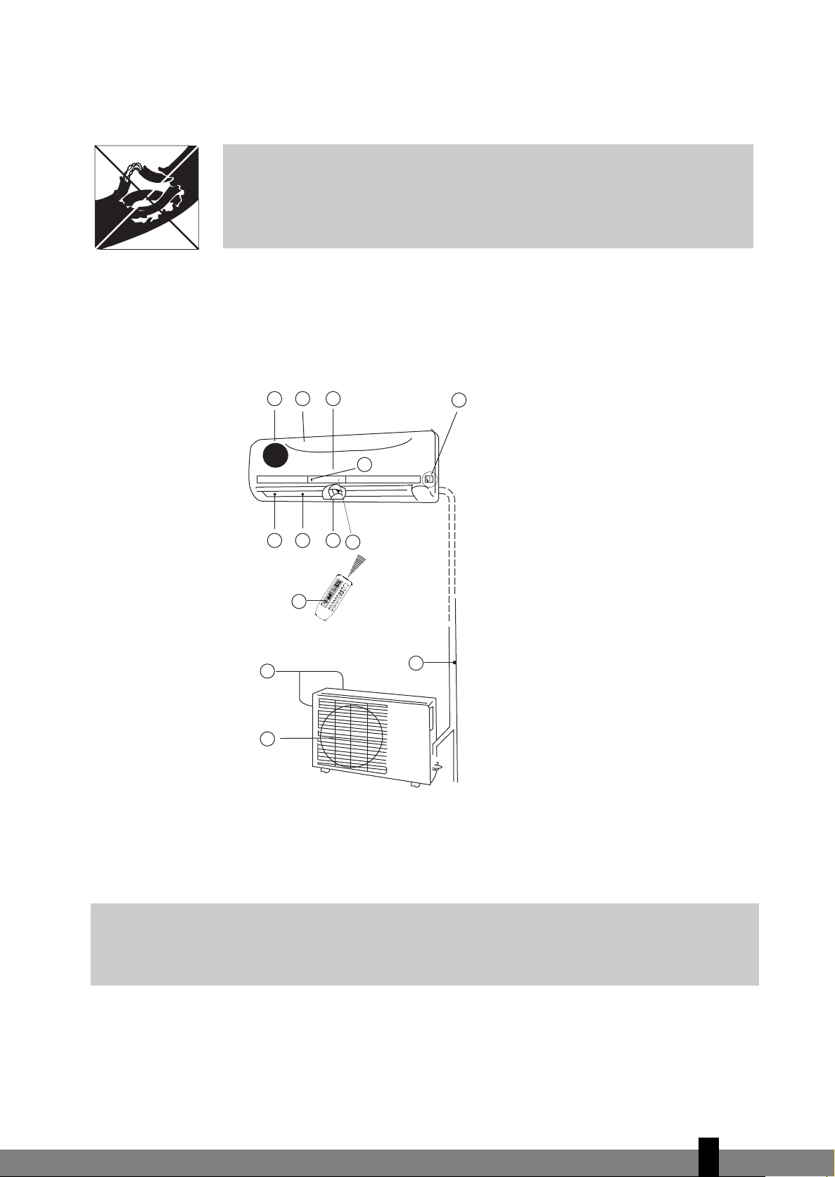
B PART NAMES
INDOOR UNIT Indoor unit
a Front panel
b Air inlet
c Air filter (behind front panel)
d Air outlet
e Horizontal air flow grille
f Vertical air flow louver
g Display panel
h Remote controller signal receiver
i Remote controller (see chapter E for
j Manual control button (auto/cool)
more details and operation)
OUTDOOR UNIT Outdoor unit
k Connecting pipe, drain hose
l Air inlet (side and rear)
m Air outlet
The operation indicator lights flash rapidly (five times per second) when safety protection features come
into operation.
NOTE!
All the pictures in this manual and on the gift box are for explanation and indication purpose
G
only. They may be slightly different from the air conditioner you purchased. The actual shape
shall prevail.
4
105
Page 6
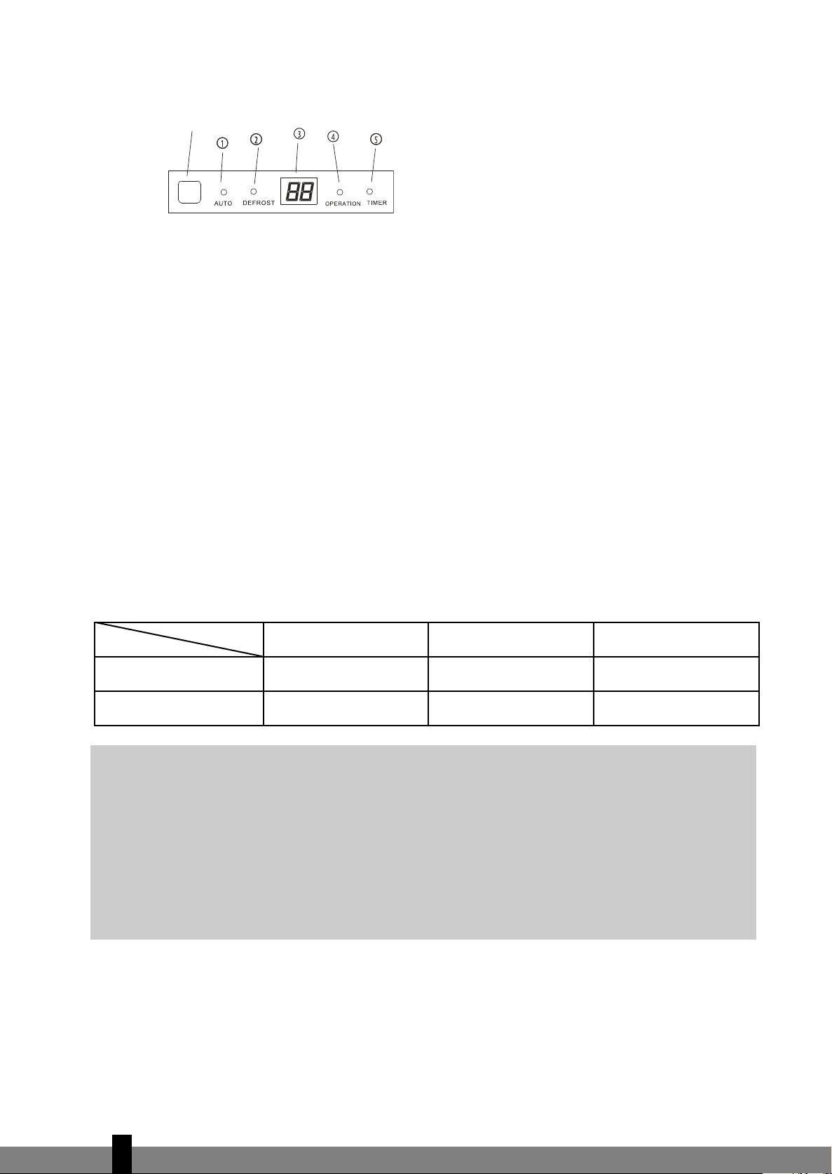
FUNCTION INDICATORS ON INDOOR UNIT DISPLAY PANEL
Signal receptor
a AUTO indicator
This indicator illuminates when the air conditioner is in AUTO operation.
b DEFROST indicator (For Cooling & Heating models only)
This indicator illuminates when the air conditioner starts defrosting automatically or when the warm
air control feature is activated in heating operation.
c TEMPERATURE indicator
Displays the temperature settings when the air conditioner is operational.
d OPERATION indicator
This indicator flashes after power is on and illuminates when the unit is in operation.
e TIMER indicator
This indicator illuminates when TIMER is set ON/OFF
.
C OPERATING TEMPERATURE
Cooling, heating and dehumidifying are most effective at the following indoor and outdoor temperatures:
Temperature
Room temperature 17ºC - 32ºC 10ºC - 27ºC 17ºC - 32ºC
Outdoor temperature 18ºC - 40ºC 10ºC - 24ºC 18ºC - 40ºC
CAUTION
• If air conditioner is used outside of the above conditions, certain safety protection features may
G
come into operation and cause the unit to function abnormally.
• Room relative humidity less than 80%. If the air conditioner operates in excess of a relative
humidity of 80% in the room, the surface of the air conditioner may attract condensation.
Please set the vertical air flow louver to its maximum angle (vertically to the floor), and set HIGH
fan mode.
• For maximum effect of your air conditioner always close doors and windows when cooling or
heating.
Mode
Cooling operation Heating operation Dehumidifying operation
4
106
Page 7
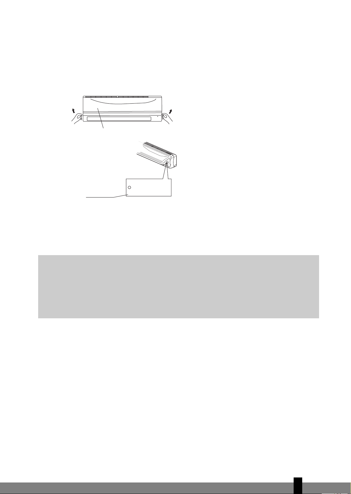
D MANUAL OPERATION
The air conditioner can be operated manually on the air conditioner itself as well as with the remote control included. For operation with the remote control please refer to chapter E “Operation with Remote
Control”. When operating without the remote control the air conditioner will only work in the AUTO-mode.
For operation without the remote control follow these instructions:
Panel
Manual control
button
1. Open and lift the front panel up to an angle until it remains fixed with a clicking sound.
2. One press of the manual control button j will lead to the AUTO operation.
3. Close the panel firmly to its original closed position.
CAUTION
• Once you push the manual button, the operation mode is shifted in an order as: AUTO, COOL,
G
OFF.
• Push the button twice, the unit will operate in forced COOL mode. This is used for testing
purposes only .
• Third press will stop the operation and turn off the air conditioner operation.
• To restore the remote controller operation, use the remote controller directly.
AUTO / COOL
4
107
Page 8

E OPERATION WITH REMOTE CONTROL
NOTE!
G
Introduction of Function Buttons on the Remote Controller
• Always aim the remote controller towards the receiver on the indoor unit and make sure there
are no obstacles in between the remote control and the receiver on the indoor unit. Otherwise
the remote control signal will not be picked up by the receiver and the air conditioner will not
work properly.
• The maximum distance at which the remote control will work is approximately 6 to 7 meters.
fig. 1
a On/off Button: Push this button to start the unit operation. Push the button again to stop the unit
operation.
b Mode Button: Each time you press the button, a mode is selected in a sequence that goes from AUTO
COOL DR
c ▲ Button: Push the button to increase the indoor temperature setting to 30ºC.
d ▼ Button: Push the button to decrease the indoor temperature setting to 17ºC.
e Fan Button: This button is used for selecting Fan Speed. Each time you press the button, a fan speed
is selected in a sequence that goes from AUTO, LOW
the AUTO or DRY mode, the fan speed will be automatically controlled and you can not set the fan
speed.
f Sleep/Turbo Button: Press this button to select SLEEP or TURBO mode. Each time you press the but-
ton, the operation mode is shifted in the direction of the arrow
DRY or FAN only, this function can not be used.
g Swing Button: Press the SWING button to activate the swing feature. Push the button again to stop.
h Air direction Button: Press this button to change the swing angle of the louver. The swing angle of
the louver is 6
ling and heating effect of the air conditioner, it would automatically change the swing direction . No
symbol will appear in the display area when press this button.
Y HEAT and FAN only as the following figure indicates:
AUTO COOL DRY HEAT FAN
, MED to HIGH, then back to Auto. When you select
SLEEP SLEEP OFF TURBO TURBO OFF
o
C for each press. When the louver swing at a certain angle which would affect the coo-
. When the operation mode is either
4
108
Page 9

i Timer on Button: Press this button to initiate the auto-on time sequence. Each press will increase the
auto-timed setting in 30 minutes increments. When the setting time displays 10Hr, each press will increase the auto-timed setting 60 minutes increments. To cancel the auto-timed program, continue pressing
the button until nothing displays.
j Timer off Button: Press this button to initiate the auto-off time sequence. Each press will increase the
auto-timed setting in 30 minutes increments. When the setting time displays 10Hr
ase the auto-timed setting 60 minutes increments. To cancel the auto-timed program, continue pressing
the button until nothing displays.
, each press will incre-
Names and Functions of indicators on Remote Controller
fig. 2
Display Panel
a TRANSMISSION Indicator:
This indicator lights when remote controller transmits signals to indoor unit.
b MODE indicator:
Displays the current operation modes. Including AUTO , COOL
HEAT only available for heat pump model.
c TEMPERATURE indicator:
Displays the temperature settings(17ºC to 30ºC).
d FAN SPEED indicator:
Displays the selected fan speed, AUTO and three fan speed levels LOW , MED , HIGH .
Displays
e SLEEP/TURBO indicator:
Each time the Sleep/Turbo button is pushed, the signal displays in the following sequence:
Nothing appears when the operating mode is either DRY or FAN only
f SWING indicator:
This indicator lights up when the SWING button is pressed.
g TIMER indicator:
The time set for timer operation is indicated. (0.5 ~ 24 hours)
(flashing) when the operating mode is either AUTO or DRY.
Nothing
Nothing
, DRY , HEAT or FAN .
G
NOTE!
All items are shown in the Fig.2 for the purpose of clear presentation But during the actual
operation only the relative functional items are shown on the display panel.
4
109
Page 10

Operating the Remote Controller
Install / Replace Batteries
Use two dry alkaline batteries (AAA/LR03).
Do not use rechargeable batteries.
1. Remove the battery cover on the back of the Remote Control by pulling it according to the arrow
direction shown on the cover.
2. Insert new batteries making sure that the (+) and (-) of battery are installed correctly.
3. Reattach the cover by sliding it back into position.
NOTE!
G
• When replacing batteries, do not use old batteries or a different type battery. This may cause
the remote controller to malfunction.
• If you do not use the remote controller for several weeks remove the batteries. Otherwise
battery leakage may damage the remote controller.
• The average battery life under normal use is about 6 months.
• Replace the batteries when there is no answering beep from the indoor unit or if the
Transmission Indicator light fails to appear.
• Never mix new and old batteries. Never use different battery types (e.g. alkaline and
manganese dioxide) simultaneously.
AUTOMATIC Operation
When the Air Conditioner is ready for use, switch on the power and the OPERATION indicator lamp on the
display panel of the indoor unit starts flashing.
1. Use the Mode select button to select AUTO.
2. Push the ▲ or ▼ button to set the desired room temperature. The most comfortable temperature settings are between 21ºC to 28ºC.
3. Push
4. Push the On/off button again to stop the unit operation.
G
the On/off button to start the air conditioner. The OPERATION lamp on the display panel of the
indoor unit lights. The operating mode is AUTO. The F
NOTE!
• In the AUTO mode, the air conditioner can logically choose the mode COOL, FAN, HEAT and
DRY by sensing the difference between the actual ambient room temperature and the set
temperature on the remote controller.
• If the AUTO mode is not comfortable for you , the desired mode can be selected manually.
AN SPEED is automatically controlled.
COOL, HEAT, and FAN ONLY Operation
1. If the AUTO mode is not comfortable, you may manually override the settings by using COOL, DRY,
HEAT (HEAT PUMP units only), or FAN ONLY modes by pressing button b.
2. Push
3. Push the Fan button e to select the FAN mode of AUTO, HIGH, MED or LOW.
4. Push the On/off button a. The operation lamp lights and the air conditioner starts to operate per your
the ▲ or ▼ button (c and d) to set the desired room temperature. When in COOLING mode, the
most comfortable settings are 21ºC or above. When in HEA
are 28ºC or below.
settings. Push the On/off button a again to stop this unit operation.
TING mode, the most comfortable settings
4
110
Page 11

NOTE!
G
The FAN ONLY mode cannot be used to control the temperature. In this mode, only steps 1, 3 and
4 are applicable.
DRY Operation
1. Push the Mode button b to select DRY.
2. Push the ▲ or ▼ button (c and d) to set the desired temperature from 21 C to 28 C.
3. Push the On/off button a. The operation lamp lights and the air conditioner starts to operate in the DR
mode. Push the On/off button a again to stop this unit operation.
NOTE!
Due to the difference of the set temperature of the unit and the actual indoor temperature, the
G
Air Conditioner when in DRY mode will automatically operate many times without running the
COOL and FAN mode.
TIMER Operation
Push Timer on/off button (i and j) to set the on and off times of the unit. The effective operation time
set by the remote controller for the timer function is limited to a period of between 0.5 and less than 24
hours.
Y
o set the STARTING time.
1. T
1.1
Push the Timer on button i, then the remote controller display shows ON TIMER, the last set time for
the starting operation and the signal "Hr" will be shown on the Timer display area. Y
to reset the time to START the operation.
1.2
Push the Timer on button i again to set desired unit start time.
1.3
After setting the Timer on ,there will be half a second delay before the remote controller transmits the
signal to the air conditioner.
2. To set the STOPPING time.
2.1
Push the Timer off button j and the remote controller display will show OFF TIMER and the last set
time for the timer off operation in hours will be shown on the Timer display area. You are now ready
to reset the time of the STOP operation.
2.2
Push the Timer off button j again to set the time you want to stop the operation.
2.3
After setting the Timer off, there will be half a second delay before the remote controller transmits
the signal to the air conditioner.
3. Set the starting & stopping time
3.1
Push the Timer on button i, the remote controller display will show ON TIMER, the last set time for
Timer on operation in hours will be shown on the Timer display area. You are now ready to readjust
the Timer on to start the operation.
3.2
Push the Timer on button i again to set the time you want to start the operation.
3.3
Push the Timer off button j, the remote controller will show OFF TIMER, the last set time for STOP
operation and the signal "Hr" will be shown on the Timer display area. You are now ready to set the
time to STOP operation.
ou are now ready
4
111
Page 12

3.4
Push the Timer off button j again to set the time you want to stop the operation.
3.5
After setting the TIMER, there will be half a second delay before the remote controller transmits the
signal to the Air Conditioner.
NOTE!
G
G
• If the same time is set for both START and STOPPING settings, the stopping time will
automatically increase 0.5hr(the set time displays less than 10Hr) or one hour (the set time
displays 10Hr or more).
• To change the Timer on/off time, just press the corresponding TIMER button and reset the
time.
• The setting time is relative time. That is the time set is based on the delay of the current time.
WARNING
• Keep the Remote Controller away from all liquids.
• Protect the Remote Controller from high temperatures and exposure to radiation.
• Keep the indoor receiver out of direct sunlight or the Air Conditioner may malfunction.
• Never mix new and old batteries. Never use different battery types (e.g. alkaline and
manganese dioxide) simultaneously.
F OPTIMAL OPERATION
To achieve optimal performance, please note the following:
• Adjust the air flow direction correctly so that it is not directly directed to people.
• Adjust the temperature to achieve the highest comfort level. Do not adjust the unit to excessive temperature levels.
• Close doors and windows otherwise the desired effect may be reduced.
• Use TIMER ON button on the remote controller to select a time you want to start your air conditioner.
• Do not put any object near air inlet or air outlet, as the efficiency of the air conditioner may be reduced and the air conditioner may stop running. Make sure there are no obstacles blocking the airflow.
The air stream must be allowed to reach the entire room unhindered. Also the air stream must be allowed to reach the air conditioner unhindered.
• Clean the air filter periodically, otherwise cooling or heating performance may be reduced. It is advised to clean the filters every two weeks.
• Do not operate unit with horizontal louvre in closed position.
4
112
Page 13

G ADJUSTING AIR FLOW DIRECTION
ff
O
/n
O
p
eel
S
na
F
gn
iw
S
n
oi
t
ce
ri
Dr
i
A
nO
r
e
m
i
T
f
fOre
m
i
T
e
do
M
.
rH
TN
O
R
E
M
I
.rH
O
ff
TRE
MI
SE
T
TPME
o
t
u
A
• Adjust the air flow direction properly otherwise, it might cause discomfort
or cause uneven room temperatures.
• Adjust the horizontal louver using button h on the remote controller.
Adjust the vertical louver manually.
•
Lever
Adjusting the horizontal Air Flow Dir
ection (up - down)
The air conditioner automatically adjusts the horizontal air flow direction in accordance with the operating mode.
To set the horizontal air flow direction
Perform this function while the unit is in operation. Keep pressing the AIR DIRECTION button h on the remote controller to move the louver to the desired direction.
Adjust the horizontal air flow direction to the desired direction.
•
• In subsequent operations, the horizontal air flow is automatically set in the
direction to which you adjusted the louver by pressing the AIR DIRECTION
button.
To set the vertical air flow direction (left - right)
Adjust the vertical louver manually using the lever on the left or right side of the
vertical louver arm (depending on model). When the air conditioner is in operation and the vertical louver is in a specific position, move the lever at left (or right,
depending on model) end of the air outlet to the desired position.
CAUTION!
G
Take care, do not touch the fan behind the vertical louvers!
NOTE!
All the pictures in this manual and on the gift box are for explanation and indication purpose
G
only. They may be slightly different from the air conditioner you purchased. The actual shape
shall prevail.
To automatically swing the air flow direction (up - down)
Perform this function while the air conditioner is in operation.
• Press the SWING g button on the remote controller.
To stop the function, press the SWING button g again. Press AIR DIRECTION h button to lock louver in
•
desired position.
4
113
Page 14
1
1
1
1
CAUTION
• The AIR DIRECTION and SWING buttons will be disabled when the air conditioner is not in
G
operation (including when the TIMER ON is set).
• Do not operate the air conditioner for long periods with the air flow direction set downward
in cooling or dry mode. Otherwise, condensation may occur on the surface of the horizontal
louver causing moisture to drop.
• Do not move the horizontal louver manually. Always use the AIR DIRECTION h or SWING
button g. If you move this louver manually
, it may malfunction during operation. If the louver
malfunctions, stop the air conditioner once and restart it.
• When the air conditioner is started immediately after it was stopped, the horizontal louver
might not move for approximately 10 seconds.
• Open angle of the horizontal louver should not be set too small, as COOLING or HEATING
performance may be impaired due to too restricted air flow area.
• Do not operate unit with horizontal louver in closed position.
• When the air conditioner is connected to power (initial power), the horizontal louver may
generate a sound for 10 seconds, this is a normal operation.
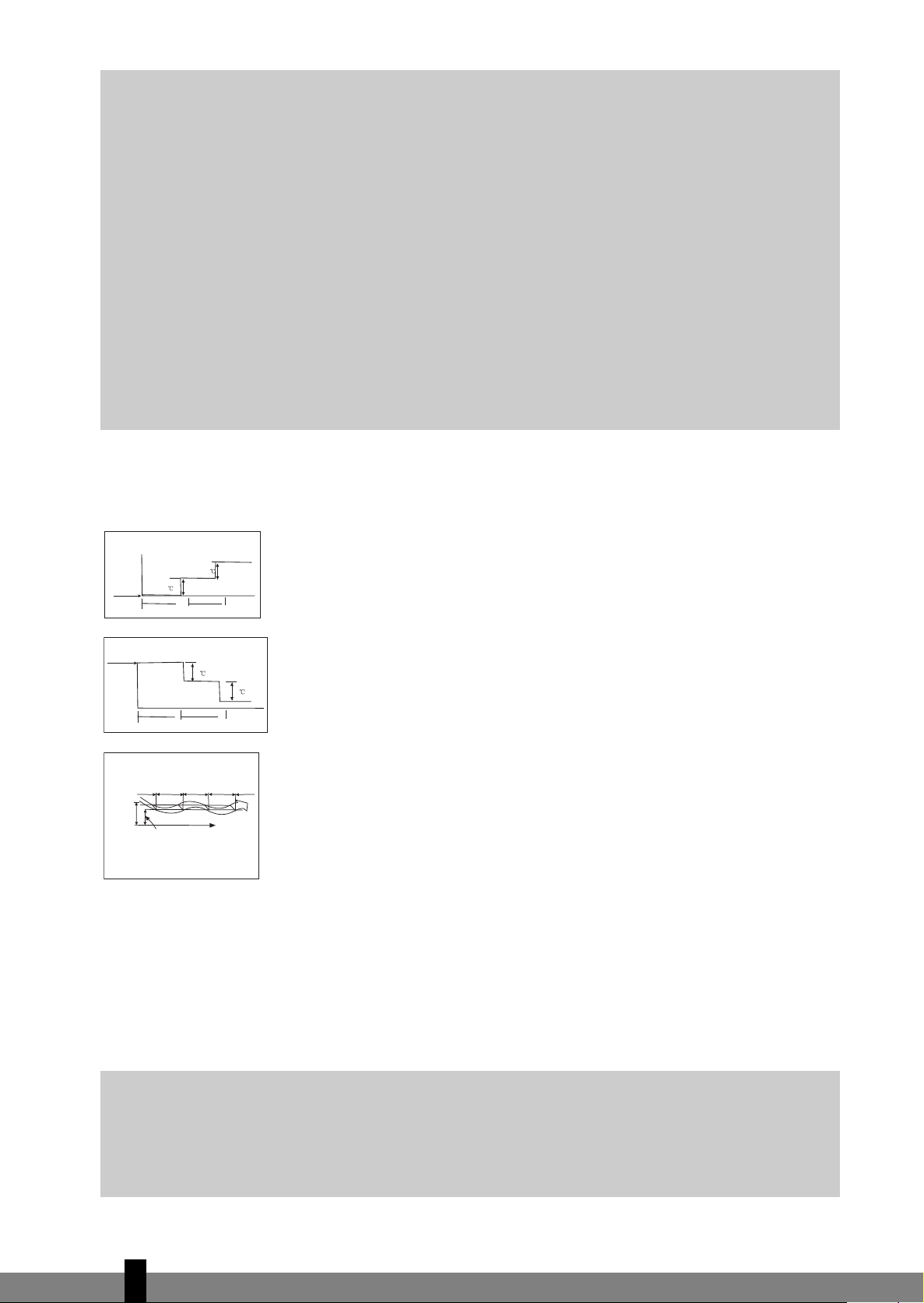
H HOW THE AIR CONDITIONER WORKS
Press Sleep button
Set
Temperature
1 hour 1 hour
COOLING
Press Sleep button
Set
Temperature
AUTOMATIC OPERATION
• When you set the air conditioner in AUTO mode (button 2 on the remote
controller), it will automatically select COOLING, HEATING or FAN only operation depending on what temperature you have selected and the room
temperature.
• The air conditioner will control room temperature automatically round the
temperature point set by you.
• If the AUTO mode is uncomfortable, you can select desired conditions manu-
1 hour 1 hour
TING
HEA
Cooling Fan only Cooling Fan only Cooling
Room
temperature
Set temperature
Time
ally.
ECONOMIC OPERATION
• When you push SLEEP button f during COOLING, HEATING or AUTO operation, the air conditioner will automatically increase (cooling) or decrease
(heating) 1ºC per hour. The set temperature will be steady 2 hours later. The
fan speed will be automatically controlled.
DEHUMIDIFYING
DEHUMIDIFYING OPERATION
• The dehumidifying mode will automatically select the dehumidifying operation based on the difference between the set temperature and the actual
room temperature.
• The temperature is regulated while dehumidifying by repeatingly turning on
and off of the cooling operation or fan only. The fan speed is LOW.
• In normal cooling operation the airconditioner will also dehumidify the air.
G
NOTE
When the airconditioner is dehumidifying it is likely that the room temperature will decrease. It is
therefore normal that a hygrostat will measure a higher relative humidity. The absolute
humidity in the room will however be lowered, depending on the amount of moisture produced
in the room (cooking, people etc).
4
114
Page 15

I MAINTENANCE
House-
hold
Drain
Cleaner
No
Thinner
WARNING
It is necessary to stop the air conditioner and disconnect the power
G
supply before cleaning.
Cleaning the indoor unit and remote controller
CAUTION
G
• Use a dry cloth to wipe the indoor unit and remote controller.
• A cloth dampened with cold water may be used on the indoor unit if
it is very dirty.
• The front panel of the indoor unit can be removed and cleaned with
water. Then wipe it with a dry cloth.
• Do not use a chemically treated cloth or duster to clean the unit.
• Do not use benzine, thinner, polishing powder, or similar solvents for
cleaning. These may cause the plastic surface to crack or deform.
Filter handle
Cleaning the air filter
A clogged air filter reduces the cooling efficiency of this unit. Clean the filter once
every 2 weeks.
1. Lift the indoor unit panel up to an angle until it stops with a clicking sound.
2. Take hold of the handle of the air filter and lift it up slightly to take it out
from the filter holder, then pull it downwards.
3. Remove the AIR FILTER from the indoor unit.
• Clean the AIR FILTER once every two weeks.
• Clean the AIR FILTER with a vacuum cleaner or water.
• Ensure before replacing that the filter is completely dry and has no defects.
4. Install the air freshening filter back into position.
5. Insert the upper portion of air filter back into the unit taking care that the
left and right edges line up correctly and place filter into position.
4
115
Page 16

Maintenance
If you plan to idle the unit for a long time, perform the following:
1. Operate the fan for about 6 hours to dry the inside of the unit.
2. Stop the air conditioner and disconnect power. Remove the batteries from the remote controller.
3. The outdoor unit requires periodic maintenance and cleaning. This should only be done by an authorized airconditioning engineer.
Checks before operation
• Check that the wiring is not broken or disconnected.
• Check that the air filter is installed.
• Check if the air outlet or inlet is not blocked after the air conditioner has not been used for a long time.
CAUTION
G
• Do not touch the metal parts of the unit when removing the filter. Injuries can occur when
handling sharp metal edges.
• Do not use water to clean inside the air conditioner. Exposure to water can destroy the
insulation, leading to possible electric shock.
• When cleaning the unit, first make sure that the power and circuit breaker are turned
f.
of
4
116
Page 17

J OPERATION TIPS
The following events may occur during normal operation.
1. Protection of the air conditioner.
Compressor protection
• The compressor cannot restart for 3 minutes after it stops.
Anti-cold air
• The unit is designed not to blow cold air on HEAT mode, when the indoor heat exchanger is in one
of the following three situations and the set temperature has not been reached.
A. When heating has just started.
B. Defrosting.
C. Low temperature heating.
Defrosting
• The indoor or outdoor fan stops running when defrosting.
Frost may be generated on the outdoor unit during heat cycle when outdoor temperature is low and
•
humidity is high resulting in lower heating efficiency of the air conditioner.
• During this condition air conditioner will stop heating operation periodically and start defrosting
automatically.
• The time to defrost may vary from 4 to 10 minutes according to the outdoor temperature and the
amount of frost buildup on the outdoor unit.
2. A white mist coming out from the indoor unit.
• A white mist may generate due to a large temperature dif
COOL mode in an indoor environment that has a high relative humidity.
• A white mist may generate due to moisture generated from defrosting process when the air conditioner restarts in HEAT mode operation after defrosting.
3. Low noise of the air conditioner.
• Y
• You can also hear a low "squeak" sound when the compressor is running or has just stopped run-
• A sound may be heard due to louver restoring to its original position when power is first turned on.
4. Dust is blown out from the indoor unit.
• This is a normal condition when the air conditioner has not been used for a long time or during first
5. A peculiar smell comes out from the indoor unit.
• This is caused by the indoor unit giving off smells permeated from building material, from furniture,
ou may hear a low hissing sound when the compressor is running or has just stopped running. This
sound is the sound of the refrigerant flowing or coming to a stop.
ning. This is caused by heat expansion and cold contraction of the plastic parts in the unit when the
temperature is changing.
use of the unit.
or smoke.
ference between air inlet and air outlet on
4
117
Page 18

6. The air conditioner turns to FAN only mode from COOL or HEAT mode.
• When indoor temperature reaches the temperature setting on air conditioner, the compressor will
stop automatically
when the indoor temperature rises on COOL mode or falls on HEAT mode to the set point.
7. Dripping water may generate on the surface of the indoor unit when cooling in a high relatively
humidity (relative humidity higher than 80%). Adjust the horizontal louver to the maximum air outlet position and select HIGH fan speed.
8. Heating mode
• The air conditioner draws in heat from the outdoor unit and releases it via the indoor unit during
heating operation. When the outdoor temperature falls, heat drawn in by the air conditioner decreases accordingly
rence between indoor and outdoor temperature. If a comfortable temperature cannot be achieved
by the air conditioner, it is advised to use a supplementary heating device.
9. Auto-restart function.
• Power failure during operation will stop the unit completely.
The airconditioner is equipped with Auto-restart feature, when the power restores, the unit restarts
automatically with all the previous settings preserved by the memory function.
, and the air conditioner turns to FAN only mode. The compressor will start again
. At the same time, heat loading of the air conditioner increases due to larger diffe-
K TROUBLE SHOOTING TIPS
Malfunctions and Solutions
TROUBLE
G
Stop the air conditioner immediately if one of the following faults occur. Disconnect the power
and contact your supplier.
• Fuse blows frequently or circuit breaker trips frequently.
• Other objects or water penetrate the air conditioner.
• The remote controller won't work or works abnormally.
• Other abnormal situations.
• Operation indicator flashes 5 times, even after mains electricity has been disconnected and
reconnected.
4
118
Page 19
Problem Cause Solution
Power cut Wait for power to be restored.
Unit may have become unplugged.
Check that plug is securely in wall
receptacle.
Fuse may have blown.
Replace fuse / reset relay / reset
circuitbraker
Battery in Remote controller may have
been exhausted.
Replace the battery.
Distance remote controller to receiver on
the indoor unit is more than 6 to 7 meters,
or there are obstacles in between the
remote controller and the receiver.
Shorten the distance. Remove possible
obstacles. Aim the remote controller
towards the receiver on the indoor unit.
The time you have set with timer is
incorrect.
Wait or cancel timer setting.
Inappropriate temperature setting.
Set temperature correctly. For detailed
method please refer to "operation with
remote control" chapter E.
Air filter is blocked. Clean the air filter.
Doors or windows in room are open. Close the doors or windows.
Air inlet or outlet of indoor or outdoor
unit has been blocked.
Clear obstructions away first, then restart
the unit.
Compressor 3 minutes delay protection
has been activated.
Defrosting of outdoor unit being
performed.
Airconditioner is in automode
Airconditioner is in dry mode
TEMP. Indicator is not
shown
Airconditioner is in fan mode Temperature cannot be set in FAN mode
Unit does not start
Unit not cooling or
heating room very well
while air flowing out
from the air
conditioner
Wait.
Fan speed cannot be
changed
Fan speed can only be changed in HEAT,
COOL and FAN mode
If the trouble has not been corrected, please contact your supplier. Be sure to inform them of the detailed
malfunctions and unit model.
NOTE!
G
Reparation of the device should only be done by an authorized airconditioning engineer.
4
119
Page 20

L GUARANTEE CONDITIONS
The air conditioner is supplied with a 24-month guarantee, commencing on the date of purchase. All material and manufacturing defects will be repaired or replaced free of charge within this period. The following
rules apply:
1. We expressly refuse all further damage claims, including claims for collateral damage.
2. Repairs to or replacement of components within the guarantee period will not result in an extension
of the guarantee.
3. The guarantee is invalidated if any modifications have been made, non genuine parts are fitted or
repairs are carried out by third parties.
4. Components subject to normal wear, such as the filter, are not covered by the guarantee.
5. The guarantee is valid only when you present the original, dated purchase invoice and if no modifica-
tions have been made.
6. The guarantee is invalid for damage caused by neglect or by actions that deviate from those in this
instruction booklet.
7. Transportation costs and the risks involved during the transportation of the air conditioner or air con-
ditioner components shall always be for the account of the purchaser.
8. Damage caused by not using suitable Zibro filters is not covered by the guarantee.
9. Refrigerant loss and/or leakage because of incompetent (dis)connecting the units is not covered by the
guarantee conditions applicable to this product.
To prevent unnecessary expense, we recommend that you always first carefully consult the instructions for
use. Take the air conditioner to your dealer for repairs if these instructions do not provide a solution.
4
120
Page 21

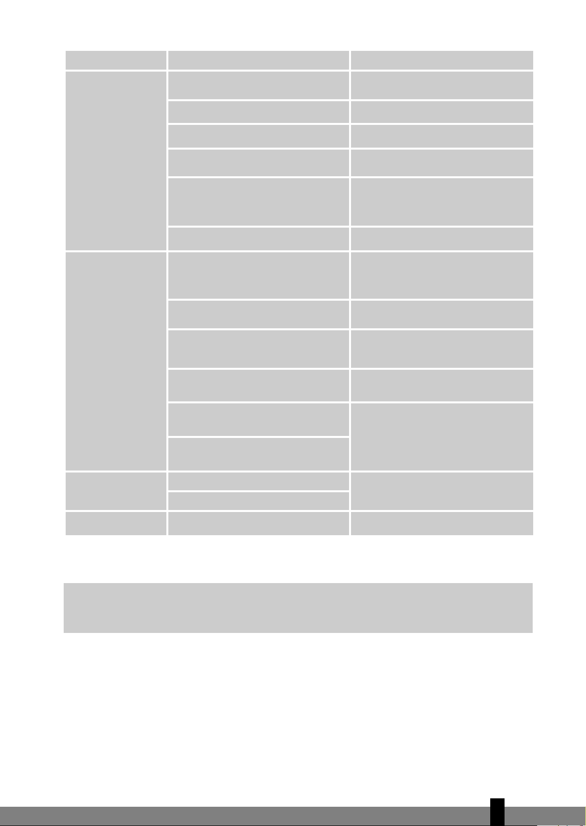
M TECHNICAL DATA
Heating performance
C B D
Current (nom.) cooling / heating
A 3.6 / 3.9 5 / 4.8 8.2 / 8.3
m3/h
420/350/290 620/550/400 800/730/600
m
3
65 - 90 85 - 110 115 -140
Controls manual / mechanic / electronic
Electronic remote Electronic remote Electronic remote
Model
SC 1226 SC 1235 SC 1246
Type air-conditioner Wall mounted split Wall mounted split Wall mounted split
Cooling capacity (max) *
EE Class* A B D
EER* 3.21 3.19 2.64
Heating capacity (max) * W 2900 3500 5350
COP* 3.3 3.43 2.83
Dehumidifying capacity ** L / 24h 24 33.6 43.2
Power consumption cooling kW 0.8 1.1 1.8
Power consumption heating kW 0.9 1 1.9
Power supply V / Hz / Ph 220 - 240 / 50 / 1 220 - 240 / 50 / 1 220 - 240 / 50 / 1
Max. Current A 5.3 7 11
Air flow **
For rooms up to**
Compressor type Rotary Rotary Rotary
Fan speeds 3 3 3
Thermostatic range ºC 17 - 30 17 - 30 17 - 30
Operating range ºC -15 - +40 -15 - +40 -15 - +40
W 2640 3500 4680
Remote control Yes / No Y Y Y
Air filter type(s) Screen, Active carbon Screen, Active carbon Carbon, Dust
Refrigerant type / charge r / gr R410A / 920 R410A/ 1100 R410A/1400
Pressure suction / discharge bar 7 / 26 7 / 26 7 / 29
Dimensions indoor unit (w x h x d) mm 790X190X275 790X190X275 940X170X275
Dimensions outdoor unit (w x h x d) mm 780X540X250 780X540X250 760X590X285
Net weight indoor unit kg 13 13.5 16
Net weight outdoor unit kg 31 35.5 42.5
Gross weight indoor unit kg 17 17.5 20.5
Gross weight outdoor unit kg 35.5 38 45
Sound pressure level indoor unit dB(A) 32 - 39 35 - 43 38 - 45
Sound pressure level outdoor unit dB(A) 53 54 58
Unit protection indoor IP IP20 IP20 IP20
Unit protection outdoor IP IP24 IP24 IP24
Fuse rating T3.15A / 250V T3.15A / 250V T3.15A / 250V
* EN 14511-2004
** To be used as indication
*** Moisture removal at 32°C, 80% RH
Waste electrical products should not be disposed with household waste. Please recycle where facilities exist. Check with your local authority or retailer for recycling advice.
Environmental information: This equipment contains fluorinated greenhouse gases covered by the Kyoto
Protocol. It should only be serviced or dismantled by professional trained personnel.
This equipment contains R410A refrigerant in the amount as stated in the table above. Do not vent R410A
into atmosphere: R410A, is a fluorinated greenhouse gas with a Global Warming Potential (GWP) = 1975
4
121
Page 22

DISTRIBUTED IN EUROPE BY PVG INTERNATIONAL B.V.
i ÖSTERREICH
PVG Austria VertriebsgmbH
Salaberg 49
3350 HAAG
tel: +43 7434 44867
fax: +43 7434 44868
email: pvgaustria@zibro.com
e BELGIË
PVG Belgium NV/SA
Industrielaan 55
2900 SCHOTEN
tel:
+32 3 326 39 39
fax: +32 3 326 26 39
email: pvgbelgium@zibro.com
q SCHWEIZ
PVG Schweiz AG
Salinenstrasse 63
4133 PRATTELN
tel: +41 61 337 26 51
fax: +41 61 337 26 78
email: pvgint@zibro.com
2 DEUTSCHLAND
PVG Deutschland GmbH
Siemensstrasse 31
47533 KLEVE
tel: 0800 - 9427646
fax: +31 (0)412 648 385
email: pvgdeutschland@zibro.com
6 DANMARK
Appliance A/S
Blovstroed Teglvaerksvej 3
DK-3450 ALLEROED
tel: +45 70 205 701
fax: +45 70 208 701
email: appliance@appliance-group.com
4 UNITED KINGDOM
Scott Brothers Ltd.
The Old Barn, Holly House Estate
Cranage, Middlewich, CW10 9LT UK
tel.: +44 1606 837787
fax: +44 1606 837757
email: sales@scottmail.co.uk
> ITALIA
PVG Italy SRL
Via Niccolò Copernico 5
50051 CASTELFIORENTINO (FI)
tel:
+39 571 628 500
fax: +39 571 628 504
email: pvgitaly@zibro.com
u NORGE
Appliance Norge AS
Vogellunden 31
1394 NESBRU
tel: +47 667 76 200
fax: +47 667 76 201
email: appliance@appliance-group.com
1 NEDERLAND
PVG International B.V.
.O. Box 96
P
5340 AB OSS
tel: +31 412 694 694
fax: +31 412 622 893
email: pvgnl@zibro.com
9 PORTUGAL
Gardena, Lda
Recta da Granja do Marquês
ALGUEIRÃO
2725-596 MEM MARTINS
tel: + 35 21 92 28 530
fax: + 35 21 92 28 536
email: pvgint@zibro.com
5 ESPAÑA
PVG España S.A.
Pol. Ind. San José de Valderas II
Comunidad ”La Alameda”
C/ Aurora Boreal, 19
28918 LEGANÉS (Madrid)
tel: +34 91 611 31 13
fax: +34 91 612 73 04
email: pvgspain@zibro.com
3 FRANCE
PVG France SARL
4, Rue Jean Sibélius
B.P. 185
76410 SOTTEVILLE SOUS LE VAL
tel: +33 2 32 96 07 47
fax: +33 0 820 34 64 84
email: pvgfrance@zibro.com
FFIINN
SUOMI
Appliance Finland Oy
Piispantilankuja 6C
02240 ESPOO
tel:
+358 9 4390 030
fax: +358 9 4390 0320
email: appliance@appliance-group.com
: POLSKA
PVG Polska Sp. z. o. o.
ul. Kościelna 110
26-800 Białobrzegi
tel:
+48 48 613 00 70
fax: +48 48 613 00 70
email: pvgpoland@zibro.com
= SVERIGE
Appliance Sweden AB
Sjögatan 6
25225 HELSINGBORG
tel: +46 42 287 830
fax:
+46 42 145 890
email: appliance@appliance-group.com
TTRR
TURKEY
PVG Is›tma Klima So¤utma Ltd.fiti.
Tepekule is merkezi
Anadolu Cad. No: 40 K:3 D:306
35010 BAYRAKLI/IZMIR
tel: + 90 232 461 51 01
fax: + 90 232 461 51 85
email: pvgturkey@zibro.com
PVG Traffic avg©072120 man_SC1226 - SC1235 - SC1246
 Loading...