

Zibro S2041, S2053, S2035 user manual

S2035 - S2041 - S2053
4
SERVICE MANUAL
2
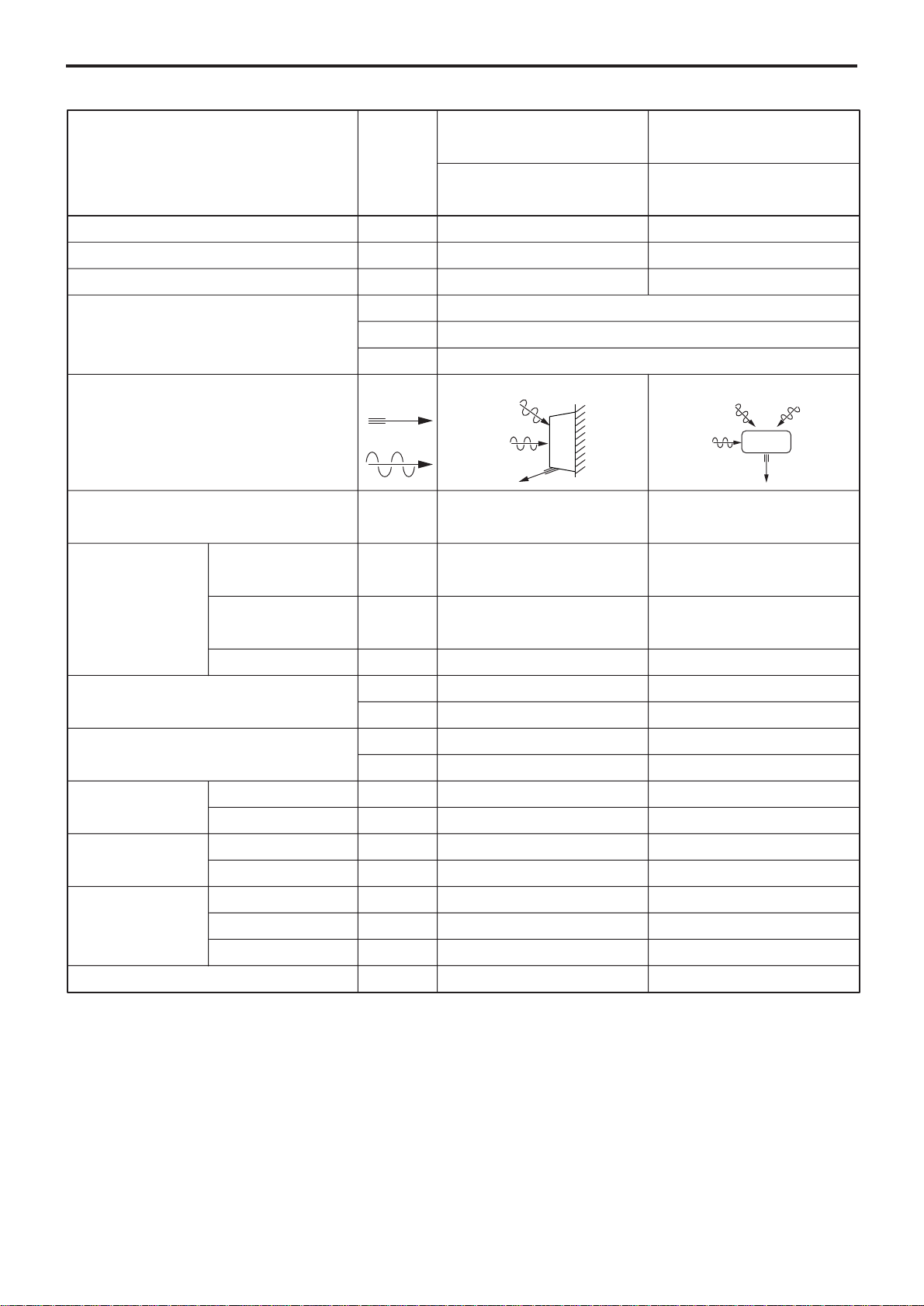
Unit
SPECIFICATION
INDOOR OUTDOOR
TAN-A28EWI TAG-A28EWI
Moisture Removal
Power source
Airflow Method
Air circulation (at High)
Input
Electrical Data
Piping Connection Port (Flare piping)
Pipe Size (Flare piping)
Drain hose
Power Cord
Dimensions
Net Weight
Running Current
Starting Current
Inner diameter
Length
Length
Number of core-wire
Height
Width
Depth
BTU/hCooling Capacity
BTU/hHeating Capacity –
L/h
phase
V
Hz
OUTLET
INTAKE
3
m/min
W
A
A
inch
inch
inch
inch
mm
m–
m–
mm
mm
mm
kg
10,000(2,700-12,000)
13,200(2,400-18,000)
1.6
Single
230
50
SIDE VIEW
Cooling ;
Heating ;
Cooling ;
Heating ;
Cooling ;
Heating ;
; Half Union 1/4''
L L
; Half Union 3/8''
G G
L (liquid side) ; 1/4''
G (gas side) ; 3/8''
core-wire/ 1 mm –
9.0
11.0
660
765
2.9
3.4
3.4
; 2-way valve 1/4''
; 3-way valve 3/8''
L (liquid side) ; 1/4''
G (gas side) ; 3/8''
14
0.6
1.4
2
295
799
210
9.1
–
–
TOP VIEW
–
–
–
–
–
550
780
278
35
– 1 –

Unit
SPECIFICATION
INDOOR OUTDOOR
TAN-A28EWI TAG-A28EWI
Type
Air Circulation
Heat Exchanger
Refrigerant Control Device
Refrigerant (R410A )
Thermostat
Timer
Air Filter
Parts Provided
Motor Type
Rated Output
W
g (oz)
Cross-flow Fan Propeller Fan
DC brushless(8-pole) DC brushless (8-pole)
30 40
Plate fin configuration,forced draft
21.2FPI 18.1 FPI
–
–
Electronic Control
Real time dual ON/OFF
7-hour OFF
Mold-proof
1 Mounting plate
2 Remote controller
3 Battery (2 pcs.)
4 Remote controller holder
5 Screw cap (2 pcs.)
6 Drain elbow
7 Gum Bushing (2 pcs.)
8 Vibration proof rubber (4 pcs.)
Expansion Valve
1,100(38.8)
–
–
–
Specifications are subject to change without notice.
– 2 –

Unit
SPECIFICATION
INDOOR OUTDOOR
TAN-A32EWI TAG-A32EWI
Moisture Removal
Power source
Airflow Method
Air circulation (at High)
Input
Electrical Data
Piping Connection Port (Flare piping)
Pipe Size (Flare piping)
Drain hose
Power Cord
Dimensions
Net Weight
Running Current
Starting Current
Inner diameter
Length
Length
Number of core-wire
Height
Width
Depth
BTU/hCooling Capacity
BTU/hHeating Capacity –
L/h
phase
V
Hz
OUTLET
INTAKE
3
m/min
W
A
A
inch
inch
inch
inch
mm
m–
m–
mm
mm
mm
kg
12,500(2,700-14,100)
17,100(2,400-20,700)
1.7
Single
230
50
SIDE VIEW
Cooling ;
Heating ;
Cooling ;
Heating ;
Cooling ;
Heating ;
; Half Union 1/4''
L L
; Half Union 3/8''
G G
L (liquid side) ; 1/4''
G (gas side) ; 3/8''
core-wire/ 1 mm –
9.5
12.5
885
1,130
3.9
5.0
5.0
; 2-way valve 1/4''
; 3-way valve 3/8''
L (liquid side) ; 1/4''
G (gas side) ; 3/8''
14
0.6
1.4
2
295
799
210
9.1
–
–
TOP VIEW
–
–
–
–
–
550
780
278
35
– 3 –

Unit
SPECIFICATION
INDOOR OUTDOOR
TAN-A32EWI TAG-A32EWI
Type
Air Circulation
Heat Exchanger
Refrigerant Control Device
Refrigerant (R410A )
Thermostat
Timer
Air Filter
Parts Provided
Motor Type
Rated Output
W
g (oz)
Cross-flow Fan Propeller Fan
DC brushless(8-pole) DC brushless (8-pole)
30 40
Plate fin configuration,forced draft
21.2FPI 18.1 FPI
–
–
Electronic Control
Real time dual ON/OFF
7-hour OFF
Mold-proof
1 Mounting plate
2 Remote controller
3 Battery (2 pcs.)
4 Remote controller holder
5 Screw cap (2 pcs.)
6 Drain elbow
7 Gum Bushing (2 pcs.)
8 Vibration proof rubber (4 pcs.)
Expansion Valve
1,100(38.8)
–
–
–
Specifications are subject to change without notice.
– 4 –

Unit
SPECIFICATION
INDOOR OUTDOOR
TAN-A53EWI TAG-A53EWI
Moisture Removal
Power source
Airflow Method
Air circulation (at High)
Input
Electrical Data
Piping Connection Port (Flare piping)
Pipe Size (Flare piping)
Drain hose
Power Cord
Dimensions
Net Weight
Running Current
Starting Current
Inner diameter
Length
Length
Number of core-wire
Height
Width
Depth
BTU/hCooling Capacity
BTU/hHeating Capacity –
L/h
phase
V
Hz
OUTLET
INTAKE
3
m/min
W
A
A
inch
inch
inch
inch
mm
m–
m–
mm
mm
mm
kg
17,700(1,700-18,800)
23,800(1,700-33,400)
2.8
Single
230
50
SIDE VIEW
Cooling ;
Heating ;
Cooling ;
Heating ;
Cooling ;
Heating ;
; Half Union 1/4''
L L
; Half Union 3/8''
G G
L (liquid side) ; 1/4''
G (gas side) ; 3/8''
core-wire/ 2 mm –
14.0
15.0
1,845
1,800
8.1
7.9
8.1
; 2-way valve 1/4''
; 3-way valve 3/8''
L (liquid side) ; 1/4''
G (gas side) ; 3/8''
14
0.6
2.3
2
295
799
210
9.5
–
–
TOP VIEW
–
–
–
–
–
550
780
278
35
– 5 –

Unit
SPECIFICATION
INDOOR OUTDOOR
TAN-A53EWI TAG-A53EWI
Type
Air Circulation
Heat Exchanger
Refrigerant Control Device
Refrigerant (R410A )
Thermostat
Timer
Air Filter
Parts Provided
Motor Type
Rated Output
W
g (oz)
Cross-flow Fan Propeller Fan
DC brushless(8-pole) DC brushless (8-pole)
30 40
Plate fin configuration,forced draft
21.2FPI 18.1 FPI
–
–
Electronic Control
Real time dual ON/OFF
7-hour OFF
Mold-proof
1 Mounting plate
2 Remote controller
3 Battery (2 pcs.)
4 Remote controller holder
5 Screw cap (2 pcs.)
6 Drain elbow
7 Photo-Catalytic Anti-Odor filter (2 pcs.)
8 Static,Catechin filter (2 pcs.)
9 Gum Bushing (2 pcs.)
Expansion Valve
1,100(38.8)
–
–
–
Specifications are subject to change without notice.
– 6 –

FUNCTIONS
REMOTE-CONTROL TRANSMITTER
ON/OFF
Operation mode selection
COOL
DRY
HEAT
AUTOMATIC
INDOOR UNIT
Sensing the room temperature
Room temperature sensor (thermistor)
Time delay safety control
Restarting is inhibited for approximately
3 minutes.
Indoor fan speed control
High, Med, Low
Air flow selection
AUTOMATIC
HIGH
MEDIUM
LOW
Room temperature setting
16°C 〜30°C
Timer operation selection
CONTINUOUS operation
OFF
ON
Sleep
Timer / time setting
Operation stops at the set time
(OFF timer)
Operation starts at the set time
(ON timer)
0.5〜 7.0hours(Sleep timer)
Operation indication lamps (LED)
(GREEN).......Light up in operation
(YELLOW) .... Timer in operation
(GREEN).......Outdoor unit operate
Dry operation mode
AUTOMATIC
Room temperature control
Maintains the room temperature in
accordance with the setting temperature.
Deice (defrost) control
Deicing operation automatically starts
when the heating efficiency is declined by
the ice formed in the outdoor unit.
After deicing operation, heating operation
automatically starts with “Hot start
function.”
Air flow direction control
Auto angle selection
Auto swing mode
Manual mode
– 7 –

Hot-start control (heating)
The indoor fan stops until the evaporator
piping temperature will be reached.
Anti-freezing control for the
evaporator
Compressor will be stopped when the
evapolator’s piping temperature is below
2℃ for one minute.
Compressor will be restarted when the
evaporator’s piping temperature is above
2℃.
Airflow direction control
Automatic airflow direction control
The louver automatically swings up and
down (cooling, dry)...horizontal and 35°
downward.
The louver is set at 70° downward
during heating operation.
FUNCTIONS
OUTDOOR UNIT
Inverter control
Inverter control reduce the ON/OF times
of compressor,so can keep the room
temperature changeless during
operation.
Auto recovery function
If there is any power failure during
operation, operation status before power
failure is memorized.
3〜 4 minutes after power recovery, the
unit restarts automatically with previous
operation status memorized.
(3〜 4 minutes is protective time for
compressor.)
Attention
Because of Auto recovery function, if
shutting off the power supply during
operation, the unit may restart
irrespective your intention when turning
on the power supply next time.
If the unit is not to be used for a long
time, shut off the power supply after
terminating all operation with remote
controller.
Electricity consumption
Inverter control can operate with less
electricity consumption than normal air
conditioner.
Deice(Defrost) control
(for outdoor unit panel)
Deice operation automatically starts
when the outdoor temperature is lower
than 2℃ and the ice is formed on the
bottom of outdoor unit.
– 8 –
SERVICE FUNCTION EXPLANATION
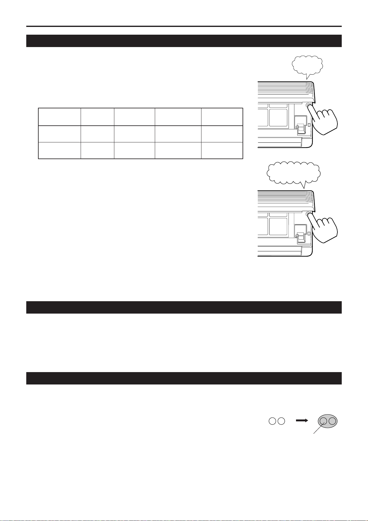
EMERGENCY AND TEST OPERATION
Emergency Operation
•
Use this operation only when the remote controller is out of order or lost.
•
When the emergency operation switch is pressed, beep starts once, which
means the start of this operation.
•
In this operation, the system automatically selects the operation modes, cooling
(or heating when available) according to the room temperature, as follows.
Beep
Temperature
ABOVE 23℃
BELOW 23℃
•
It is not possible to operate in dry mode.
Operation
mode
COOLING
HEATING
Designated
temperature
26℃
23℃
Timer mode Air flow
CONTINUOUS
CONTINUOUS
AUTOMATIC
AUTOMATIC
Test Operation
Test operation switch is same as emergency one.
•
Use this operation only for testing the performance of the machine in
the condition where the room temperature is less than 16°C.
•
Continue to press the test operation switch for more than 5 seconds.
After you hear twice beep, release your finger from the switch
: the cooling operation starts with the air flow speed “HI.”
•
If the test operation switch is pressed more than 10 seconds, it doesn’t
work.
•
After 30 minutes, test operation ends automatically.
Twice beep
HOW TO RELEASE EMERGENCY AND TEST OPERA TION
• In case of releasing during those operations, you can either push emergency operation switch once more or
apply operation using remote control.
You will hear a beep sound and emergency/ test operation is released.
• If you release the operation by remote control, operation will continue as setting of the remote control
automatically.
INTERFERENCE PREVENTION OF SIGNALS FROM THE REMOTE CONTROLLER
When two indoor units used in the same room, interference of the signals may happen. To avoid this, alternative
signal model B can be selected by the following. (Ex-factory setting is mode A)
J1
• Remote controller side : Have “J1” on the PC board short-circuited by soldering.
• Indoor unit side : Cut “R13” on the PC board.
Soldering
J1
– 9 –

OPERATION DETAILS
TIMER OPERATION
ON Timer operation
•
Press the ON/OFF switch. Right after replacing new batteries, set the present time in advance.
•
Set the “ON T ime” : Press the “TIME ADJ” button twice.
Adjust the time with the “ , ” button.
Press the “TIME ADJ” button twice.The setting of “ON Time” is completed and the present time appears on the LCD.
•
Set the “ON Timer” : Press the Timer fixing button “ON”.
OFF Timer operation
•
Press the ON/OFF switch. Right after replacing new batteries, set the present time in advance.
•
Set the “OFF T ime” : Press the “TIME ADJ” button 3 times.
Adjust the time with the “ , ” button.
Press the “TIME ADJ” button once.The setting of “OFF Time” is completed and the present time appears on the LCD.
•
Set the “OFF Timer” : Press the Timer fixing button “OFF”.
Sleep Timer operation
•
Press the “SLEEP” button during the operation.
•
Set the operating period by pressing the “SLEEP” button until the period designated appears on the LCD.
Timer Cancellation
•
ON/OFF Timer : Press the Timer fixing button “ON”(On Timer) and/or “OFF”(Off Timer) once again.
•
Sleep Timer : Press the “SLEEP” button until the operating period on the LCD disappears.
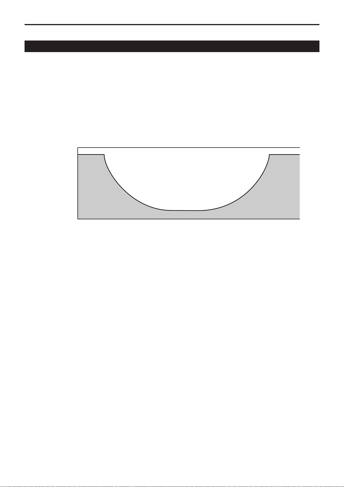
AIRFLOW DIRECTION CONTROL
Vertical adjustment
When ON/OFF switch is pressed, the vertical louver will move to the adequate positions for each operation
automatically.
Swing of air flow
If air flow direction switch is pressed once, the vertical louver will move within the range of figures.
Fixing the flow direction
If air flow direction switch is pressed again, the vertical louver will be fixed and that position is memorized.
From the next operation the louver will be set at previous position automatically.
Notes :
•
In Swing Mode, the louver automatically moves up and down within the certain range, as the illustration below .
•
There is two different ranges of louver swinging; one is of cooling & dry mode operation and the other is of
heating operation.
Standard Position
Approx.10 degrees
(Cooling/Dry)
Approx.70 degrees
(Heating)
Level
Swing of Air Flow
Level
Approx.10
degrees
Approx.40
degrees
Cooling
Dry
Heating
– 10 –
Approx.45
degrees
Approx.70
degrees

AIRFLOW DIRECTION CONTROL
OPERATION DETAILS
Horizontal Adjustment
Swing of Air Flow
The horizontal louver will keep moving steadly right and left if the horizontal louver button is pressed once.
Fixing the Flow Direction
The horizontal louver will come to a halt if the horizontal louver button is pressed once again.
NOTICE :
•
Dew drops may appear at the outlet under high humidity(e.g.during rainy season) if the system is operated
with the horizontal louver faced to the extreme right or left.
•
Use the wireless remote control unit without fail to change the angle of the horizontal louver. The horizontal
louver may move out of the normal range if forced by hands.
TAN/TAG-A53EWI
TIME DELAY SAFETY CONTROL FUNCTION - FOR PROTECTION OF COMPRESSOR
•
Compressor will not restart, in any operation modes, for 3 minutes after its stop.
•
Compressor does not stop during the first 6 minutes of its operation even if the room temperature reaches to
the designated temperature, except changing setting temperature.
COOLING MODE OPERATION
•
The compressor will stop when operational frequency reached the minimum frequency and that condition has
been kept for 6 minutes and the room temperature becomes 1℃ lower than it was set.
•
The compressor will re-start when room temperature becomes 0℃ higher than it was set.
•
The operational frequency will be set every ★1 seconds of operation.
The operational frequency setting will be calculated based on the deviation of the room temperature and the
set temperature on one end and the deviation factor at the time of previous setting on another.
Room temperature
Designated
temperature
0˚C
-1˚C
MAX
★2
Frequency of
compressor
MAX
★2
0
Hz
TAN/TAG-A28EWI, TAN/TAG-A32EWI
TAN/TAG-A53EWI
MIN★3
– 11 –
★1
40
120
MIN★3
★2
90Hz
100Hz
★3
24Hz
10Hz

OPERATION DETAILS
TAN/TAG-A28EWI, TAN/TAG-A32EWI
DRY MODE OPERATION
• Compressor stops when the room temperature fall to 0.3°C lower than the designated temperature
continuously for 2 minutes.
• Compressor restarts when room temperature rises to the designated temperature.
• The operating frequency of the compressor is determined according to the room temperature
(see the diagram below).
Indoor fan
Designated
temperature
+6.0
+5.3
+4.7
+4.0
+3.3
+2.7
+1.7
+1.0
+0.0
-0.7
Designated
Fan blow
Super
low
Stop
Room temperature
2min.
Super
low
Designated Fan blow
Operating
frequency of
compressor
Indoor fan
98Hz 90Hz
70
66
62
58
5252
4848
Selected
speed
Super
low
OFF
(3min.)
Super
low
Selected speed
– 12 –
OPERATION DETAILS
TAN/TAG-A53EWI
DRY MODE OPERATION
•
During dry mode operation, both motors (TAN,TAG) run proportionally according to the temperatures (indoor,
outdoor).
•
The compressor runs continuously while unit is operating. (see the diagram below)
MAX
30Hz
Operating
frequency of
compressor
MAX
30Hz
MIN15Hz
– 13 –
 Loading...