

ZETTLER AZ955-1C-3DSE, AZ955-1C-3DE, AZ955-1C-24DSE, AZ955-1C-24DE, AZ955-1C-9DSE Datasheet
...
NOTES
1. All values at 20°C (68°F).
2. Relay may pull in with less than “Must Operate” value.
3. Other coil resistances and sensitivities available upon request.
4. Specifications subject to change without notice.
ZETTLERelectronics
Telephone +44 (0) 1582 599 600 Fax +44 (0) 1582 599 700
Logistic Design (UK) Limited. Unit 3, Eagle Centre Way, Luton LU4 9US www.zettlerrelay.com sales@zettlerrelay.com
2000-10-04
AZ955
COIL
Power
At Pickup Voltage Standard coil:113 mW
(typical) Sensitive coil: 84 mW
Max. Continuous .5 W at 20°C (68°F) ambient
Dissipation
Temperature Rise Standard: 33°C (59°F) at nominal
coil voltage
Sensitive: 25°C (45°F) at nominal
coil voltage
Temperature Max. 105°C (221°F)
GENERAL DATA
Life Expectancy Minimum operations
Mechanical 10 million operations
Electrical 1 x 10⁵at rated load
Operate Time (typical) Standard: 3 ms at nominal coil voltage
Sensitive: 5 ms at nominal coil voltage
Release Time (typical) 1 ms at nominal coil voltage
(with no coil suppression)
Capacitance Coil to contact: 3.0 pF
Contact to contact: 3.0 pF
Bounce (typical) At 10 mA contact current
2 ms at operate
8 ms at release
Dielectric Strength 1250 Vrms coil to contact
(at sea level for 1 min.) 500 Vrms between open contacts
Meets FCC Part 68.302 1500 V lightning surge
Meets FCC Part 68.304 1000 V dielectric
Insulation 100 megohms min. at 20°C, 500 VDC,
Resistance 50% RH
Dropout Greater than 10% of nominal coil voltage
Ambient Temperature At nominal coil voltage
Operating Standard: -40°C (-40°F) to 70°C (158°F)
Sensitive: -40°C (-40°F) to 80°C (176°F)
Storage Both: -25°C (-13°F) to 105°C (221°F)
Vibration 0.039" DA at 10–55 Hz
Shock 10 g
Enclosure P.B.T. polyester
Terminals Tinned copper alloy
Max. Solder Temp. 270°C (518°F)
Max. Solder Time 5 seconds
Max. Immersion Time 30 seconds
Weight 1.8 grams
SUBMINIATURE
PC BOARD RELAY
FEATURES
• Subminiature size for high density packaging
• DIL pitch terminals
• Epoxy sealed for automatic wave soldering
• High sensitivity: 150 mW nominal with 84 mW pickup
• Meets FCC Part 68.302 1500 V lightning surge
• Meets FCC Part 68.304 1000 V dielectric
• UL file E43203; CSA file LR 702514
CONTACTS
Arrangement SPDT (1 Form C)
Bifurcated crossbar contacts
Ratings Resistive load:
Light Duty Max. switched power: 30 W or 60 VA
Max. switched current: 1 A
Max. switched voltage: 60 VDC or 125 VAC
UL Rating: 1 A at 30 VDC
0.3 A at 60 VDC
0.5 A at 125 VAC
Material Silver alloy, gold clad
Resistance < 100 milliohms initially
2000-10-04
ZETTLERelectronics
Telephone +44 (0) 1582 599 600 Fax +44 (0) 1582 599 700
Logistic Design (UK) Limited. Unit 3, Eagle Centre Way, Luton LU4 9US www.zettlerrelay.com sales@zettlerrelay.com
AZ955
RELAY ORDERING DATA
COIL SPECIFICATIONS: STANDARD COIL
Nominal Must. Max. Coil
Coil Operate Continuous Resistance
ORDER NUMBER
VDC VDC VDC ±10%
1.5 1.1 2.4 11.3 AZ955-1C-1.5DE
3 2.3 4.7 45.0 AZ955-1C-3DE
5 3.8 7.9 125 AZ955-1C-5DE
6 4.5 9.5 180 AZ955-1C-6DE
9 6.8 14.2 405 AZ955-1C-9DE
12 9.0 19.0 720 AZ955-1C-12DE
24 18.0 37.9 2880 AZ955-1C-24DE
COIL SPECIFICATIONS: SENSITIVE COIL
Nominal Must. Max. Coil
Coil Operate Continuous Resistance
ORDER NUMBER
VDC VDC VDC ±10%
1.5 1.1 2.7 15.0 AZ955-1C-1.5DSE
3 2.3 5.5 60.0 AZ955-1C-3DSE
5 3.8 9.1 167 AZ955-1C-5DSE
6 4.5 11.0 240 AZ955-1C-6DSE
9 6.8 16.4 540 AZ955-1C-9DSE
12 9.0 21.9 960 AZ955-1C-12DSE
24 18.0 43.8 3840 AZ955-1C-24DSE
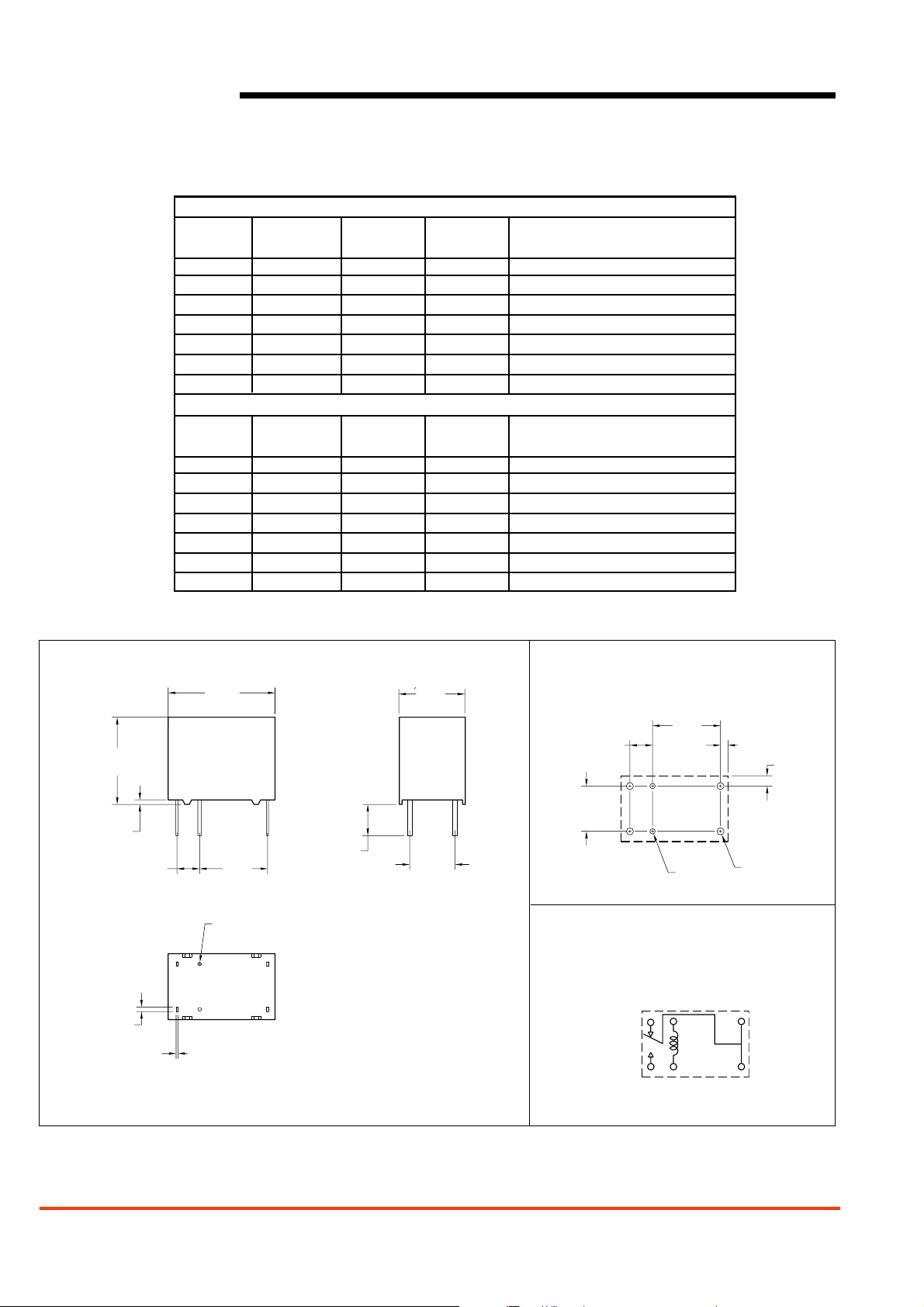
MECHANICAL DATA
Dimensions in inches with metric equivalents in parentheses. Tolerance: ± .010"
PC BOARD LAYOUT
Viewed toward terminals
WIRING DIAGRAM
Viewed toward terminals
.385
[9.8]
.020
[0.5]
.100
[2.5]
4x.020
[0.5]
4x.008
[0.2]
.472
[12.0]
2xø.016
[ø0.4]
.300
[7.6]
.138
[3.5]
TYP
.291
[7.4]
.200
[5.1]
.100
[2.5]
.200
[5.1]
12 5
.300
[7.6]
2xø.024
[ø0.6]
.033
[0.84]
4xø.032
[ø0.8]
.045
[1.15]
10 9 6
 Loading...