

Page 1

Page 2

Page 3

Instruction
This workshop manual describes the main maintenance items and procedures and
troubleshooting for the Husqvarna Zenoah engine blower.
This manual is classified into two categories; one includes important notices concerning
disassembly and reassembly including "Cautions for disassembly" and "Cautions for
reassembly", the other includes inspection and adjustment items such as "Muffler inspection
and maintenance", "Air cleaner inspection" and "Carburetor adjustment". After each item is
thoroughly understood, apply the understanding to the actual maintenance tasks.
Frequently asked questions are also included in this manual. However, many cases need rich
maintenance experience and informed judgment. Please refer to this manual for maintenance
support.
【【【【NOTES】】】】
1. The contents of this manual are based on specifications as of January 2009.
The contents may be modified due to performance improvement or some other reason
without notice.
2. Use Zenoah brand-name parts when replacing a part during maintenance, etc.
The manufacturer does not bear any responsibility if trouble occurs during parts use of other
than brand-name parts.
3. Read this manual thoroughly before beginning the maintenance work, understand it, apply
the content to the actual maintenance tasks and guide the customer if directions, are
needed.
Page 4

Exported models according to country
This workshop manual applies to all exported engine blower models sold by Hasqvarna
Zenoah. Some models are not exported to particular regions of the world. Please check your
model by referring the following table.
Table of exported models corresponding to country
Category Handheld Blower Backpack Blower
Displacement 22.5 cm
3
25.4 cm3 29.5 cm3 41.5 cm3 47.9 cm3 50.2 cm3 62.0 cm3 64.9 cm3 71.9 cm3
Engine Type G23L GZ25N GZ30N G4K GZ48N GZ51N G62L GZ65N GZ72N
JAP HB2311EZ EBZ3000 EB4300
★
EBZ4800 EB7001
★
General HB2302 HBZ2601 EBZ3000 EB4300
EB6200
EB7000
EBZ8001
*
2
EU HB2302 HBZ2601 EBZ3000 EBZ4800 EB7000 EBZ8001
*
2
Blower
Model
USA HBZ2601
EBZ3000RH
EBZ3050RH
EBZ5100
★
EBZ5100RH
EBZ5100Q
★*
1
EBZ5150★
EBZ5150RH
EBZ5150Q
★*
1
EBZ7100
★
EBZ7100RH
EBZ7150
★
EBZ7150RH
EBZ8001
★
EBZ8001RH
EBZ8050
★
EBZ8050RH
★: Left hand throttle lever specifications
*1: EBZ5100Q has low noise specifications.
*2: Equipped with frame for the mist kit installation.
Page 5
Model Notation
The engine type and blower model nomenclature is as follows.
The applicable blower models and series names are indicated at right of the maintenance item
title. Refer to this nomenclature to confirm engine type and blower model.
●●●● Engine Type
G Z 25 N
Engine series (L/ N/ K)
Displacement (cm3)
Strato charged engine (green engine)
●●●● Blower Model
HB Z 26 01
Minor changed code
Handheld Bower
EB Z 71 00
Backpack (shouldering type) Blower
EB Z 51 00 RH
Right hand throttle lever specification
EB Z 51 00 Q
Low noise specifications
EB Z 51 50
Evaporation tank (fluorine coated) specification
(Since January, 2009.)
Page 6

Contents
1. Special Features
............................................................................................................ 1
2. Specifications and Technical Data
2-1 Blower ........................................................................................................................... 2
2-2 Pipe ............................................................................................................................... 3
2-3 Overall dimensions ........................................................................................................ 4
3. Special Tools
3-1 Rotor Removal .............................................................................................................. 5
3-2 Module Assembly ........................................................................................................ 11
3-3 Recoil Pulley Removal ................................................................................................ 14
3-4 Piston Pin Removal ..................................................................................................... 15
4. Service Guide
4-1 Starter Pulley Removal ............................................................................................... 17
4-2 Air Inlet Net Removal .................................................................................................. 17
4-3 Upper Spring Damper Removal .................................................................................. 18
4-4 Volute Cover Lower Damper Removal ........................................................................ 19
4-5 Flywheel Side Crankshaft Removal ............................................................................ 19
4-6 Crankcase Oil Seal and Bearings Removal ................................................................ 20
4-7 Crankcase Assembling ............................................................................................... 21
4-8 Piston Inserting Direction ............................................................................................ 24
4-9 Piston Pin Snap Ring Assembly ................................................................................ 24
4-10 Positioning of Lead Air Intake Tube .......................................................................... 25
4-11 Reed Valve Assembly ............................................................................................... 25
4-12 Gasket Assembly ...................................................................................................... 26
4-13 Scavenging Duct Cover Assembly ............................................................................ 27
4-14 Muffler Assembly ....................................................................................................... 27
4-15 Switch Cord Assembly .............................................................................................. 28
4-16 Cable Wiring .............................................................................................................. 30
4-17 Fan Assembly ........................................................................................................... 31
4-18 Backpack Pad Air Supply Pipe Assembly ................................................................. 31
4-19 Upper Spring Damper Assembly .............................................................................. 31
4-20 Upper Damper Assembly .......................................................................................... 32
4-21 Lower Damper Assembly .......................................................................................... 32
4-22 Carburetor Assembly ................................................................................................ 33
4-23 Engine Cover Assembly ............................................................................................ 33
4-24 Check of the Gasket Assembly ................................................................................. 34
4-25 Spark Arrester Removal ............................................................................................ 35
4-26 Spark Arrester Cleaning ............................................................................................ 36
4-27 Muffler Cleaning ........................................................................................................ 36
4-28 Air Cleaner Inspection ............................................................................................... 37
4-29 Element Removal ...................................................................................................... 37
4-30 Element Cleaning ...................................................................................................... 39
Page 7

5. Structure of Right Hand Throttle Lever
............................................................. 40
6. Carburetor
6-1 Specifications .............................................................................................................. 41
6-2 Carburetor Configuration ............................................................................................ 42
6-3 Carburetor Conforms to Exhaust Emissions Regulations .......................................... 43
6-4 Limiter Cap Removal/ Installation ............................................................................... 44
6-5 Idling Speed Adjustment ............................................................................................. 44
6-6 Carburetor Inspection ................................................................................................. 45
6-7 Carburetor Adjustment ................................................................................................ 47
7. Maintenance Standards
7-1 Engine ......................................................................................................................... 51
7-2 Tightening Torques ...................................................................................................... 52
8. Troubleshooting
8-1 Engine does not start .................................................................................................. 53
8-2 Engine stop during operation ...................................................................................... 53
8-3 Engine cannot be stopped .......................................................................................... 53
8-4 Lack of output power or unstable revolution ............................................................... 54
8-5 The amount of the wind is weak ................................................................................. 54
Page 8

Page 9

1
1. Special Features
The environmental friendly Strato
Charge Engine is installed.
The exhaust gas toxin concentration is greatly
reduced without need for a catalyst, to generate
reactive heat. High engine cooling performance
promotes stable output even during continuous
operation in summer. Furthermore, low fuel
consumption reduces running costs.
Strato Charged: It means prior air intake and
layered scavenging system.
Strato charged engine installed models:
HBZ2601
EBZ3000
EBZ4800
EBZ5100
EBZ5100Q
EBZ7100
EBZ8001
The fan is designed to deliver air
efficiently and silently.
Usually an open type fan is used,
whose vanes are bare. Some
fans have closed construction
whose vane edges are joined to a
plate.
The closed vane fan will deliver a
larger airflow compared to the
same sized conventional open
vane fan.
Closed vane fan installed model:
EBZ8001
The backpack blower has air ventilation system between the blower's pad
and operator's back to reduce sweating and ensure comfortable operation.
Exhaust Type:
Cools the operator's back by
exhausting air between the blower's
pad and operator's back.
Exhaust models:
EB4300/ EBZ4800/ EBZ5100 Series
EB6200/ EB7000/ EB7001/ EBZ7100
Inhalation Type:
Cools the operator's back by
sucking air between the blower's
pad and operator's back.
Inhalation models:
EBZ3000 EBZ8001
A large air cleaner, incomparable to other manufacturer's models,
is installed. The large air cleaner consist of two stage filters
(pre-filter and paper filter).
An extended cleaning interval compared to conventional models
ensures easier maintenance and trouble-free operation.
●●●● Air cleaner performance: Twice that of conventional models.
●●●● Cleaning interval: Three times longer than any other
manufacturer's blower of the same class.
Large air cleaner employing models:
EB7000
EB7001
EBZ7100
EBZ8001
V
olute Case
Frame
Guard Net
Engine Centrifugal Fan
Guard Net
Open Vane Fan
Closed Vane Fan
Backpack Pad Ventilation
Large Air Cleaner
Nozzle Shapes of the Pipe End Main Purpose
A larger diameter promotes
voluminous air blowing.
It is suitable for blowing
withering fallen leaves, paper
trash and other light material.
A narrower nozzle generates
higher air pressure.
It is suitable for blowing trimmed
turf, pine needles and other
moist or weighty material.
A wide nozzle spreads the
blown air.
It is suitable for trimmed turf and
fallen leaves that stick to the
ground.
Noise Comparison between Models
Pipe End Specifications and Characteristics
Model
Noise dB (A)
15 m (49 ft)
from the
blower
Noise
level
EBZ4800 67 Low
EBZ5100Q 68
HBZ2601 69
EBZ3000 69
HB2302/ 2311 70
HBZ2601CA 72
EBZ5100 71
EB4300 74
EB6200/ 7000/ 7001 75
EBZ7100 77
EBZ8001 77 High
Pre-filter
Air Cleaner Cover
paper Filter
Air Cleaner Body
Fuel/ air mixture
and pure air are
separately induced
durin
g p
iston
Firstly pure air is
inhaled, then fuel/
air mixture is
inhaled.
A pure air layer
forms to push out
the burnt gasses
resulting in a
reduced volume of
unburnt exhaust
gasses.
V
entilation
φφφφ72 mm (2.84 in.)/
φφφφ66 mm (2.60in.)
φφφφ57 mm (2.24 in.)
B
A
Duckbill Nozzle
Dimensions (A x B)
Small nozzle: 23x138 mm (0.91x5.43 in.)
Large nozzle: 30x180 mm (1.18x7.09 in.)
Pipe End
φφφφ72 mm (2.84 in.)/
φφφφ66 mm (2.60in.)
Pipe End
φφφφ57 mm (2.24 in.)
Duckbill Nozzle
Operating area
To prevent leaves, dirt or foreign matter being
drawn in, a net is set between the volute cover
and the frame.
If leaves or dirt block at the net and the air
intake, airflow and blower cooling efficiency will
be reduced resulting in overheating.
Guard net installed models:
EBZ3000
EBZ4800
EBZ5100
EBZ5100Q
EB7000
EB7001
EBZ7100
EBZ8001
15 m
(49 ft)
Under ANSI B175.2-2000; (8 points measurement)
15 m
(49 ft)
Page 10

2
2. Specifications and Technical Data
2-1 Blower ★:
★:★:
★:Left hand throttle lever specifications
Item Unit Specifications
Category Handheld Blower Backpack Blower
Engine Type G23L GZ25N GZ30N G4K GZ48N GZ51N G62L GZ65N GZ72N
HB23 Series HBZ26 Series EBZ30 Series ---- ---- EBZ51 Series ---- EB70 Series EBZ71 Series EBZ80 Series
EBZ3000 EBZ8001
Blower Model
HB2302 HB2311EZ HBZ2601 HBZ2601
EBZ3000RH/
EBZ3050RH
EB4300 EBZ4800
EBZ5100/
EBZ5100RH/
EBZ5150/
EBZ5150RH
EBZ5100Q/
EBZ5150Q
EB6200 EB7000 EB7001
EBZ7100/
EBZ7100RH/
EBZ7150/
EBZ7150RH/
EBZ8001/
EBZ8001RH/
EBZ8050/
EBZ8050RH
JAP, EU, General
EU, General
Sales Region
(Reference)
EU, General JAP EU, General USA
USA
JAP, General
JAP, EU, General
USA US A Gen eral EU, Genera l JAP U SA
USA
Remarks
Cycle - 2 ← ← ← 2 ← ← ← ← ← ← ← ← ←
Number of Cylinders -
1
← ← ←
1
← ← ← ← ← ← ← ← ←
Valve Type - Piston valve ← ← ← ← ← ← ← ← ← ← ← ← ←
Cylinder Bore
mm (in.) 32 (1. 260)
←
34 (1.339)
←
38 (1.496) 40 (1.575) 43 (1.693) 44 (1.732)
←
47.5 (1.870)
← ← ←
50 (1.969)
Stroke mm (in.) 28 (1.102) ← ← ← 26 (1.024) 33 (1.299) ← ← ← 35 (1.378) ← ← 36.6 (1.441) ←
Displacement
cm3 22.5
←
25.4
←
29.5 41.5 47.9 50.2
←
62
← ←
64.9 71.9
Effective
Compression Ratio
- 7.7 ← 8 7.4 7.4 8.1 8 7.8 7.3 7.7 ← ← 7.4 7.5
Fuel -
Gasoline/oil mixed fuel
← ← ← ← ← ← ← ← ← ← ← ← ←
Engine lubrication - Fuel-oil mixture ← ← ← ← ← ← ← ← ← ← ← ← ←
Engine lubrication Oil
-
2-cycle oil
← ← ← ← ← ← ← ← ← ← ← ← ←
Mixing Ratio -
Zenoah FC 40:1
Normal FB 25:1
RedMax FD 50:1
← ← ← ← ← ← ← ← ← ← ← ← ←
Type -
Diaphragm type
rotary valve
← ← ← ← ← ← ← ← ← ← ← ← ←
Carburetor
(Walbro)
Model
-
WYJ-110A WYJ-374 WYA-26E WYA-65
USA, EU: WYA-73B
JAP: WYA-82
WYK-67A
EU:WYA-51B
JAP:WYA-42B
WYA-79 WYA-83 WYK-73A WYK-123A
←
WYA-81 W YA -44B
Starting Method - Recoil starter
Recoil starter
(Coil dumper type: EZ)
Recoil starter ←
Recoil starter
(Coil dumper type: EZ)
Recoil starter ← ← ← ← ← ← ← ←
Type
-
Analog controlled
TCI Flywheel
Magneto with
advance-angle
←
Analog controlled
CDI Flywheel
Magneto with
advance-angle
← ← ← ←
Digital controlled
CDI Flywheel
Magneto with
advance-angle
Analog controlled
CDI Flywheel
Magneto with
advance-angle
← ← ←
Digital controlled
CDI Flywheel
Magneto with
advance-angle
←
Digital control Misfire
for excessive speed
Maximum speed:
85000 rpm
Ignition
System
Model -
UK-08922-01
←
UK-08922-35
←
USA: UK-08958C-31
JAP, EU: UK-08958-31
ZMG-8 ZMG-10G UK-08963-54 ZMG-10G ZMG-8
← ←
ZMG-14CGD ZMG-14GD
Ignition Timing °/ rpm 24/ 6000 ← 35/ 7000 ← 37/ 7500 28/ 7000 35/ 7000 33/ 7000 35/ 7000 28/ 7000 ← ← 34/ 7000 33/ 7000
Type -
RCJ6Y
←
CMR7A CMR7H
←
RJ6C CMR7H
← ←
BPMR7A
← ←
CMR7H
←
Spark Plug
Gap
mm (in.)
0.6~0.7
(0.024~0.028)
← ← ← ← ← ← ← ← ← ← ← ← ←
Type -
Primary coil
short-circuiting
← ← ← ← ← ← ← ← ← ← ← ← ←
LH - No setting Push type No setting Push type Toggle type No setting ← Push type ← ←
Stopping
Method
Switch
RH -
Push type ← ← ←
Slide type ← ← ← ← ← ← No setting Slide type ←
Cooling System -
Forced air cooling
← ← ← ← ← ← ← ← ← ← ← ← ←
Air Cleaner
Element Type
-
Single layer dry
element
← ← ← ←
Single layer
half-wet element
Dual layer
half-wet element
Single layer
half-wet element
← ←
Primary: Dry puff
Secondary: Dry paper
← ← ←
Output Axle Rotation
Direction
-
Counterclockwise
← ← ← ← ← ← ← ← ← ← ← ← ←
View from output
axle
Length mm (in.) 325 (12.8) ← 327 (12.9) ← 313 (12.3) 335 (13.2) 352 (13.9) 401 (15.8) ← 336 (13.2) ← 365 (14. 4) 371 (14.6)
380 (15.0)/
USA: 390 (15.4)
Width mm (in.) 225 (8.86) 233 (9.17) 268 (10.55) 269 (10.59) 394 (15.5)
★489 (19.3)
/ 454 (17.9)
452 (17.8)
★483 (19.0)
/ 441 (17.4)
★483 (19.0)
★489 (19.3)
/ 454 (17.9)
449 (17.7) ★485 (19.1)
★487 (19.2)
/ 467 (18.4)
★540 (21.3)
/ 490 (19.3)
Throttle arm
Vertical state
Overall
Dimensions
Height mm (in.) 360 (14.2) ← ← ← 420 (16.5) 495 (19.5) 476 (18.7) 495 (19.5) ← ← ← ← ← 496 (19.5)
Dry Weight
kg (lbs.) 3.7 (8.16)
←
3.9 (8.6) 4 (8.82) 6.1 8.5 8.9 9.4
←
9.1 9.7
←
10.6 11.7/ USA:11.5
Elbow included,
Blower pipe excluded
Fuel Tank Capacity L 0.75 ← 0.65 ← 1. 08 1.8 1.9 2.1 ← 2 2.1 ← ← 2.3
Idling Speed
rpm 2300
←
2800 3000 3000 2000 2300 2200
←
2000
← ← ← ←
Operating Speed rpm 7500 ← 7890 7600 6700 6350 6250 6000 5700 7700 7300 ← 7050 6700
Blower Nozzle
Diameter
mm (in.) 66 (2.60)
← ← ← ← ←
66 (2.60)
Option: 55 (2.17)
66 (2.60)
← ← ← ← ←
72 (2.835)
Average air volume at
aimed blowing point
m3/ min 10 ← 10.4 ← 10.6 12 13.2 13.8 12.8 14 15 16.5 16.6 19.4
Maximum air speed at
aimed blowing point
(Calculated estimate)
m/ s 55.4
← ← ←
58.7 66.5 73.1 76.4 70.9 77.5 83.1 91.4 91.9 90.3
Maximum Output
kW/ rpm
(PS)
0.86/ 8000
(1.17)
←
←
0.88/ 7500
(1.2)
0.86/ 7500
(1.17)
0.95/ 7500
(1.29)
1.80/ 8000
(2.45)
1.88/ 8000
(2.56)
1.62/ 7500
(2.2)
1.53/ 7500
(2.08)
2.87/ 7500
(3.9)
3.1/ 7000
(4.1)
3.1/ 7000
(4.1)
2.98/ 8000
(4.05)
3.29/ 8000
(4.48)
Fuel Consumption
L/ h 0.8
←
0.59 0.51 0.59 1.7 1.05 1. 1 0.98 1.9
← ←
1.65 1.85
Under actual blower
state
Ambient noise at
15 m from the blower
dB (A) 70 ← 69 72 69 74 67 71 68 75 ← ← 77 77 ANSI B175.2-2000
Noise at operator
(Reference value)
dB (A) 91
←
95 92 91 99 92 94 92 97 99
←
100 100
Sound Power Level dB (A) 106 ← 106 ← 100 106 104 104 102 110 107 ← 110 112 ISO 11094
Page 11
3
2. Specifications and Technical Data
2-2 Pipe
Unit: mm (in.)
Part Name Grip Assembly Vacuum Kit Pipe End Straight Pipe++++Duckbill Nozzle
Form
Standard D=φ60 (2.36) D=φ74 (2.91) D=φ80 (3.15) φ73 (2.87)×φ66 (2.60) φ73 (2.87)×φ57 (2.24) φ79 (3.11)×φ66 (2.60) φ79 (3.11)×φ72 (2.84) Forφ73 (2.87) Forφ79 (3. 11)
RedMax Lodo 6811-51220 (Standard) 2756-51220 (Option) 848-L5C-65E1 (S tandard) 848-L58-65E1 (Standard)
Part
Number
Solid Color
3495-51400
(Option)
2750-51501
(Standard)
848-L58-6521
(Standard)
-
(Option)
848-L0L-65E0 (Standard) 848-L38-65E0 (Option) 848-L5K-65E1 (Standard) 848-L5Z-65E 0 (Standard)
6811-51211+6811-51230
(Option)
848-L58-65D0+848-L58-65L0
(Option)
EB430/
EBE440
●
●
+(2750-51200 Swivel Joint)
HB2302/
HB2311EZ/
HBZ2601
-
-
-
● ● ● (Option) ●
EBZ3000
-
-
-
● ● (Option)
●
EB4300/
EB6200/
EB7000
● ● ● (Option) ●
EBZ4800
●
● ● (Standard)
●
EBZ5100Q ● ● ● (Option) ●
EBZ5100/
EB7001
●
● ● (Option)
●
EBZ7100 ● ● (Standard) ● (Option) ●
Model
EBZ8001
●
● (Option) ● (Standard)
●
Part Name Flexible Pipe Swivel Joint Straight Pipe Silencer Pipe End
Form
Diameter: D φ87 (3.43) φ87 (3.43) φ94 (3.70) φ99.5 (3.92) φ70 (2.76) φ70 (2.76) φ80 (3.15) φ61 (2.40) φ74 (2.91) φ80 (3.15) φ74 (2.91) φ61 (2. 40) φ73 (2.84) φ73 (2.87) φ79 (3.11) φ79 (3.11)
Diameter: D1 φ70 (2.76) φ70 (2.76) φ70 (2.76) φ80.5 (3.17) φ60 (2.36) φ74 (2.91) φ79 (3.11) φ60 (2.36) φ73 (2.87) φ79 (3.11) φ73 (2.87) φ57 (2.24) φ66 (2.60) φ57 (2.24) φ66 (2.60) φ72 (2.84)
Standard
Length: L 420 (16.54) 372 (14.65) 345 (13.58) 345 (13.58) 370 (14.57) 340 (13.39) 365 (14.37) 370 (14.54) 320 (12.60) 365 (14.37) 346 (13.62) 355 (13.98) 340 (13.39) 340 (13.39) 340 (13.39) 340 (13.39)
RedMax Lodo
-
6811-51220 2756-51220 848-L5C-65E1 848-L58-65E1
Part
Number
Solid Color
3495-51110 T4017-51110 T4030-51110 848-L65-65A0 3495-51202 2750-51201 848-L58-6511 3495-51321 6811-51211 848-L58-65D0 T4030-51110
3495-51300 848-L0L-65E0 848-L38-65E0 848-L5K -65E1 848-L5Z-65E0
EB430/
EBE440
●
●
●
-
●
HB2302/
HB2311EZ/
HBZ2601
-
-
-
-
-
-
-
●
-
●
EBZ3000
●
●
●
-
●
EB4300/
EB6200/
EB7000
● ● ●
-
●
EBZ4800
●
●
-
-
-
●
● ●
EBZ5100Q ● ●
-
-
-
● ●
EBZ5100/
EB7001
●
●
●
-
●
EBZ7100 ● ● ●
-
●
Model
EBZ8001
●
●
●
-
●
Diameter: D
φ66
(2.60)
φ57
(2.24)
φ66
(2.60)
φ72
(2.84)
23 (0.91)
138 (5.43)
D
D1
L
D
D1
L
D
D1
L
D
D1
L
D
D1
L
30 (1.18)
180 (7.19)
Page 12
4
2. Specifications and Technical Data
2-3 Overall dimensions
Handheld Blower
Backpack Blower
Unit: mm (in.)
Blower Type A B C D
HB2302 325 (12.8) 225 (8.86) 360 (14.2) 610 (24.0)
HB2311EZ 325 (12.8) 233 (9.17) 360 (14.2) 610 (24.0)
HBZ2601 268 (10.55)
HBZ2601 (USA)
327 (12.9)
269 (10.59)
360 (14.2) 610 (24.0)
Unit: mm (in.)
Blower Type A B BB C D
EBZ3000/ 3000RH/ 3050/ 3050RH
313
(12.3)
―
394
(15.5)
420
(16.5)
1222
(48.11)
EB4300
335
(13.2)
489
(19.3)
454
(17.9)
495
(19.5)
1222
(48.11)
EBZ4800
352
(13.9)
―
452
(17.8)
476
(18.7)
1248
(49.13)
EBZ5100/ 5100RH/ 5150/ 5150RH
401
(15.8)
483
(19.0)
441
(17.4)
495
(19.5)
1195
(47.05)
EBZ5100Q/ 5150Q
401
(15.8)
483
(19.0)
―
495
(19.5)
1221
(48.07)
EB6200
336
(13.2)
489
(19.3)
454
(17.9)
495
(19.5)
1222
(48.11)
EB7000
336
(13.2)
―
449
(17.7)
495
(19.5)
1222
(48.11)
EB7001
365
(14.4)
485
(19.1)
―
495
(19.5)
1195
(47.05)
EBZ7100/ 7100RH/ 7150/ 7150RH
371
(14.6)
487
(19.2)
467
(18.4)
495
(19.5)
1185
(46.65)
EBZ8001
380
(15.0)
EBZ8001/ 8001RH/ 8050/ 8050RH:
USA
390
(15.4)
540
(21.3)
490
(19.3)
496
(19.5)
1185
(46.65)
RH: Right hand throttle lever specification
Page 13
5
3. Special Tools
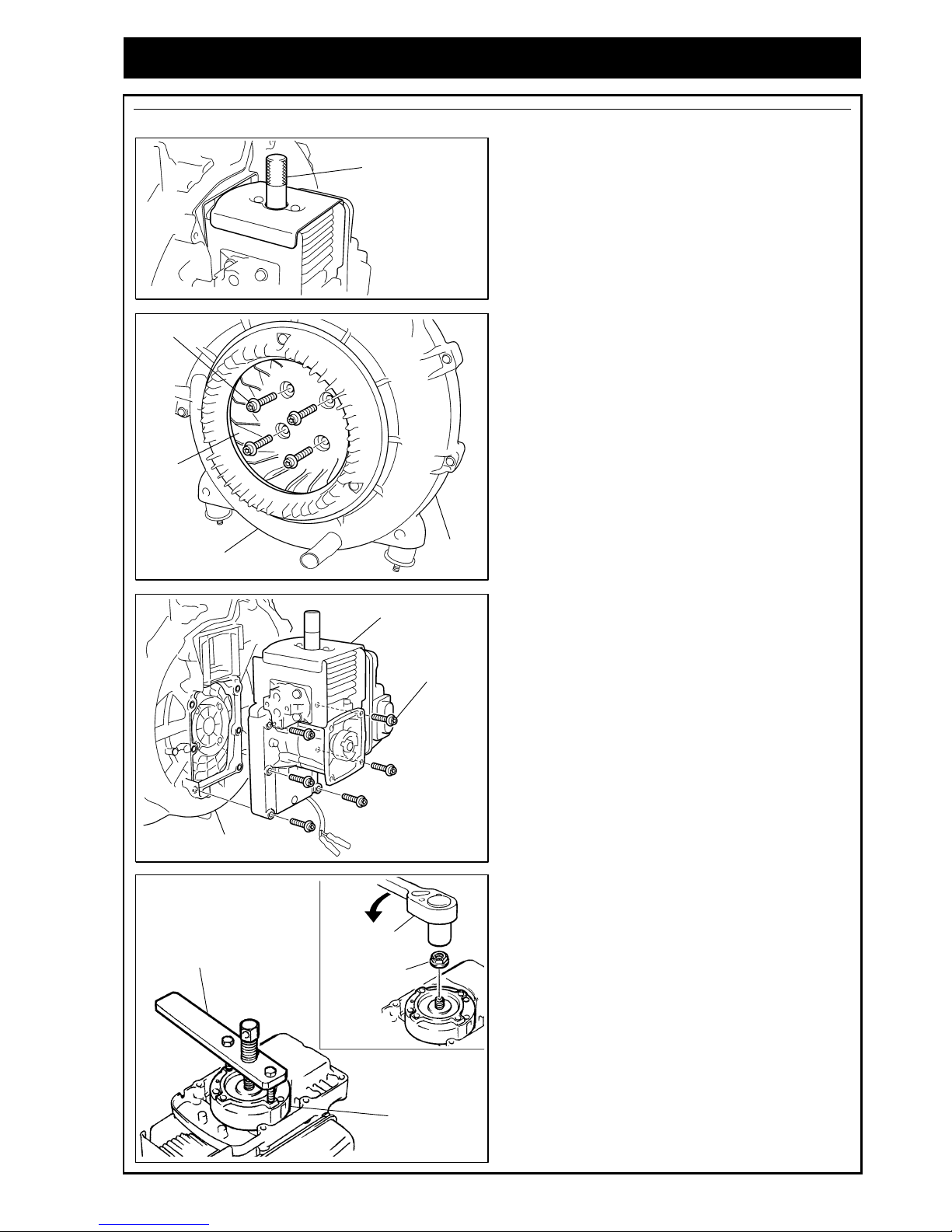
3-1 Rotor Removal
Description
Part Name
Part Number
Model
Stopper
2670-96220
1664-96410
Stopper
3350-96220
Stopper
4810-96220
Puller Assy
2890-96100
Puller Assy
1490-96101
Puller Assy
2750-96100
Wrench (HEX)
3304-97611
Size: 3/4/5 mm
Wrench (TORX)
2850-96410
Size: T20/ T25/ T27
HB23 Series ● ● ●
HBZ26 Series ● ●
EBZ30 Series ● ● ●
EB4300/ 6200
EB70 Series
● ● ●
EBZ4800
EB51/ 71/ 80 Series
● ● ●
Remove the rotor using the puller assy (special tool) while preventing piston movement by setting the stopper
(special tool).
Examples of special tool usage and maintenance procedures categorized by type and series are explained
below. Each drawing includes information on parts such as mount screws and disassembly cautions.
How to use (Procedure) Handheld Blower: HB23 Series, HBZ26 Series
1. Remove the plug, and detach the main complete
parts. Remove the carburetor, recoil starter and
fuel tank if necessary.
【【【【Disassembly Flowchart】】】】
Volute Cover Assy.
↓
Engine Cover
↓
Below the procedure
Volute Cover Assy.
Mounting Screw (5)
【【【【HB23 Series】】】】
:
(+): P5×L20
【【【【HBZ26 Series】】】】:
TORX (T27): P5×L20
Mounting Screw (7)
(+): P5×L20
Mounting Screw (7)
TORX (T27): P5×L20
【【【【HB23 Series】】】】
Mounting Screw (1)
(+): M4×L14 (PW)
Mounting Screw (2)
TORX (T27): M5×L16
*Installing with the recoil starter.
Engine Cover
Engine Cover
Engine Short Block
Volute Case
【【【【HBZ26 Series】】】】
Construction
Page 14
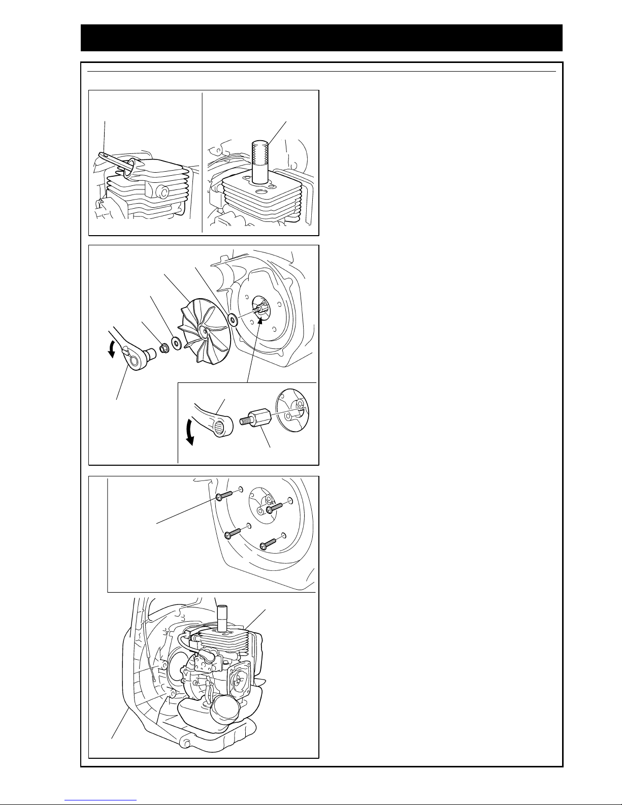
6
3. SPECIAL TOOLS
Handheld Blower: HB23 Series, HBZ26 Series
2. Set the stopper (special tool) into the plug hole.
3. Remove the mounting nut using the box wrench
then remove the fan.
4. Remove the extension using the wrench.
5. Remove the four mounting screws, separate the
volute case and the engine short block.
Stopper
【【【【HB23 Series】】】】 【【【【HBZ26 Series】】】】
Stopper
Box Wrench
(12 mm)
Mounting Nut
(12 mm Hex)
Washer
Washer
Fan
Extension
Wrench (17 mm)
Mounting Screw
【【【【HB23 Series】】】】
:
(+): M5×L14 (PW, SW)
【【【【HBZ26 Series】】】】
:
TORX (T27): M5×L14
Engine Short Block
Volute Case
Page 15
7
3. Special Tools
Handheld Blower: HB23 Series, HBZ26 Series
6. Remove the rotor using the puller assy.
Apply 8 mm puller bolts.
How to use (Procedure) Backpack Blower: EBZ30 Series
1. Remove the plug, and detach the main complete
parts. Remove the carburetor, recoil starter and
fuel tank if necessary.
Rotor
Puller Assy
Puller Bolt (8 mm)
17 mm
【【【【Disassembly Flowchart】】】】
Air Inlet Net
↓
Spring Damper
↓
Frame
↓
Volute Cover Assy
↓
Engine Cover
↓
Below the procedure
Volute Cover Assy.
Mounting Screw (8)
TORX (T27): M5×L25
Mounting Screw (3)
Mounting Bolt (1)
(+): M5×L16
Mounting Screw (3)
TORX (T27): M5×25
Engine Cover
Engine Short Block
Volute Case
Air Inlet Net
Plate
Clip (4)
Frame
Mounting Nut (2)
M6
Mounting Screw (2)
TORX (T27/ P): M5×L70
Mounting Nut (2)
M5
Lower Damper
Refer to
“4-2 Air Inlet Net Removal”
Refer to
“4-3 Upper Spring Damper Removal”
Refer to
“4-4 Volute Cover Lower Damper Removal”
Construction
Page 16
8
3. SPECIAL TOOLS
Backpack Blower: EBZ30 Series
2. Set the stopper (special tool) into the plug hole.
3. Remove the four mounting screws, then remove
the fan.
4. Remove the four mounting screws, separate the
volute case and the engine short block.
Stopper
Fan
Mounting Bolt
TORX (T27): M6×L30
Mounting Bolt
TORX (T27):
M5×L20
Engine Short Block
Volute Case
Page 17
9
3. Special Tools
Backpack Blower: EBZ30 Series
5. Remove the mounting nut using the box wrench.
6. Remove the rotor using the puller assy.
Apply 8 mm puller bolts.
How to use (Procedure)
Backpack Blower: EB4300/ 6200, EB70 Series, EBZ4800, EBZ51/ 71/ 80 Series
1. Remove the plug, and detach the main complete
parts. Remove the carburetor, recoil starter and
fuel tank if necessary.
【【【【Disassembly Flowchart】】】】
Air Inlet Net
↓
Frame
↓
Engine Cover
↓
Below the procedure
Rotor
Puller Assy.
Puller Bolt (8 mm)
Box Wrench
(12 mm)
Mounting Nut
(12 mm Hex)
Volute Cover Assy.
Mounting Screw (1)
Engine Cover
Engine Short Block
Volute Case
Lower Damper
A
ir Inlet Net
Upper Dumper
Clip (4)
Frame
Mounting Nut (2)
M6
Mounting Screw (4)
Refer to
“4-2 Air Inlet Net Removal”
Refer to
“4-4 Volute Cover Lower Damper Removal”
Refer to
“4-20 Upper Damper Assembly”
Exceptions for
EB4300/ 6200
Construction
Page 18
10
3. SPECIAL TOOLS
Backpack Blower: EB4300/ 6200, EB70 Series, EBZ4800, EBZ51/ 71/ 80 Series
2. Set the stopper (special tool) into the plug hole.
3. Remove the four mount screws, then remove the
fan. The fan is detached but stays inside the volute
cover assembly and the volute case.
4. Remove the six mounting screws then remove the
engine short block from the volute case.
5. Remove the mounting nut using the box wrench.
6. Remove the rotor using the puller assy.
Rotor
Puller Assy.
Box Wrench
(12 mm)
Mounting Nut
(12 mm Hex)
Stopper
Fan
Mounting
Bolt
Volute Cover Assy.
Volute
Case
Mounting Bolt
Engine Short Block
Volute Case
Page 19
11
3. Special Tools
3-2 Module Assembly
Description
Part Name
Part Number
Model
Gauge
3350-96240
T=0.4 mm
Gauge
2750-96240
t=0.3 mm
Gauge
848-8W4-0050
t=0.4 mm
Wrench (HEX) 3304-97611
Size: 3/ 4/ 5 mm
Wrench (TORX) 2850-96410
Size: T20/ T25/ T27
HB23 Series
HBZ26 Series
EBZ30 Series
● ●
EB4300/ 6200
EB70 Series
EBZ4800/ 5100Q
● ●
EBZ5100
EBZ71/ 80 Series
● ●
Adjust the air gap between the rotor's magnetic steel and the module using the gauge (special tool).
Module Resistance
Model Engine Type
Primary Side
(Iron Core ⇒Primary Lead)
Secondary Side
(Iron Core ⇒High Tension Lead)
Air Gap
mm (in.)
HB2302/ 2311EZ G23L 0.8 kΩ 4.23 kΩ 0.3~0.4 (0.012~0.016)
HBZ2601 GZ25N +Side 8.45 kΩ -Side 2.70 kΩ 2.92 kΩ 0.3~0.4 (0.012~0.016)
EBZ3000 GZ30N +Side 30.3 kΩ -Side 37.2 kΩ 2.04 kΩ 0.3~0.4 (0.012~0.016)
EBZ3000RH/ 3050RH GZ30N (USA) +Side 31.6 kΩ -Side 37.4 kΩ 2.05 kΩ 0.3~0.4 (0.012~0.016)
EB4300 G4K 0.17 kΩ 1.4 kΩ 0.3~0.4 (0.012~0.016)
EBZ4800 GZ48N
EBZ5100Q/ 5150Q GZ51N
0.33 kΩ 2.77 kΩ 0.3~0.4 (0.012~0.016)
EBZ5100/ 5100RH
EBZ5150/ 5150RH
GZ51N
+Side 71.2 kΩ
-Side: cannot be measured
11.0 kΩ 0.35~0.45 (0.014~0.018)
EB6200/ 7000/ 7001 G62L 0.17 kΩ 1.4 kΩ 0.3~0.4 (0.012~0.016)
EBZ7100/ 7100RH
EBZ7150/ 7150RH
GZ65N Several MΩ or higher 2.74 kΩ 0.35~0.45 (0.014~0.018)
EBZ8001/ 8001RH
EBZ8050/ 8050RH
GZ72N Several MΩ or higher 2.72 kΩ 0.35~0.45 (0.014~0.018)
The resistance values shown above are the
reference values for resistance tester
measurement. The resistance value is within
the normal range shows no internal leakage
or any other defect.
We supply the measurement equipment (gap
tester) that can measure spark energy while
the engine is running.
3699-90247
Three-point gap tester
* Connect Negative Side (black) to Iron Core.
REFERENCE
Page 20
12
3. SPECIAL TOOLS
Examples of the gauge (special tool) usages are shown according to the type of the gauge.
Gauge: 3350-96240 (T=0.4 mm) HB23 Series, HBZ26 Series, EBZ30 Series
1. Remove the obstructive parts in order to see the
rotor and the module.
(Refer to “3-1 Rotor Removal”.)
2. Insert a gauge (special tool) between the rotor
magnet metal and module. Tighten the mounting
bolts while pushing the module against the rotor.
【【【【HB23 Series】】】】
Module
Rotor
Wrench
Gauge
Mounting Bolt
【【【【HBZ26 Series】】】】
Module
Rotor
Wrench
Gauge
Mounting Bolt
【【【【EBZ30 Series】】】】
Module
Rotor
Wrench
Gauge
Mounting Bolt
Page 21
13
3. Special Tools
Gauge: 2750-96240 (T=0.3 mm) EB4300/ 6200, EB70 Series, EBZ4800/ 5100Q
1. Remove the module cover.
2. Insert a gauge (special tool) between the rotor
magnet metal and module. Tighten the mounting
bolts while pushing the module against the rotor.
Gauge: 848-8W4-0050 (T=0.4 mm) EBZ5100, EBZ71/ 80 Series
1. Remove the module cover.
2. Insert a gauge (special tool) between the rotor
magnet metal and module. Tighten the mounting
bolts while pushing the module against the rotor.
Module
Rotor
Wrench
Gauge
Mounting Bolt
【【【【EB4300/ 6200, EB70 Series】】】】
【【【【EBZ4800/ 5100Q】】】】
Module
Rotor
Wrench
Gauge
Mounting Bolt
【【【【EBZ5100】】】】
Module
Rotor Wrench
Gauge
Mounting Bolt
【【【【EBZ71/ 80 Series】】】】
Module
Rotor
Wrench
Gauge
Mounting Bolt
Page 22

14
3. SPECIAL TOOLS
3-3 Recoil Pulley Removal
Description
Part Name
Part Number
Model
Stopper
4810-96220
Puller
4500-96100
Puller
848-8W0-0020
Wrench (HEX) 3304-97611
Size: 3/ 4/ 5 mm
Wrench (TORX) 2850-96410
Size: T20/ T25/ T27
HBZ26 Series
●
●
●
EBZ71/ 80 Series
●
●
●
Remove the recoil pulley using the puller (special tool) while preventing piston movement by setting the
stopper (special tool).
Examples of the puller (special tool) usages are shown according to the type of the puller.
Puller: 4500-96100 HBZ26 Series
1. Remove the recoil starter and the spark plug.
2. Insert the stopper (special tool) to the plug hole
(Refer to “3-1 Rotor Removal”).
3. Engage the puller (special tool) to 2 holes on the
pulley and pull out the pulley.
Note: Pulley screw is right turn screw.
Puller: 848-8W0-0020 EBZ71/ 80 Series
1. Remove the recoil starter and the spark plug.
2. Insert the stopper (special tool) to the plug hole
(Refer to “3-1 Rotor Removal”).
3. Extract the pulley while holding the pulley by the
puller's pins (special tool).
Note: Pulley screw is right turn screw.
Puller
Box Wrench
Pulley
Pin
Hole
Puller
Box Wrench
Pulley
Puller
Pulley
Pin
Pin
Pin
Pin
Page 23

15
3. Special Tools
3-4 Piston Pin Removal
Description
Part Name
Part Number
Model
Rod Assy
1101-96220
φ
7.5×φ4.7
Rod Assy
3350-96230
φ11×φ
8
Rod Assy
2750-96230
φ11×
35 mm
Wrench (HEX) 3304-97611
Size: 3/ 4/ 5 mm
Wrench (TORX) 2850-96410
Size: T20/ T25/ T27
HB23 Series
HBZ26 Series
●
●
EBZ30 Series
EB4300
●
●
EB6200
EB70 Series
●
●
EBZ4800
EBZ51 Series
●
●
EBZ71/ 80 Series
●
(Only a rod is used.)
●
Remove the cylinder, and then the piston pin using the rod assy (special tool).
Examples of the rod assy (special tool) usages are shown according to the type of the rod assy.
Rod Assy: 1101-96220 HB23 Series, HBZ26 Series
1. Remove the engine short block (refer to “3-1 Rotor
Removal”) and then remove the cylinder.
2. Remove the snap rings from both sides of the
piston pin.
3. Engage the rod assy (special tool) against the
piston pin and gently tap with a plastic hammer to
push out the pin.
Hard hammering may damage the big end of
the connecting rod.
EBZ71/ 80 Series are designed so that the
piston assembly can be disassembled
without any tool. However, if it is difficult to
pull out the piston pin, use the special tool
(Rod Assy: 1101-96220) to push out the
piston pin.
Rod Assy.
Plastic Hammer
Piston
CAUTION
Rod
Piston Pin
Piston
REFERENCE
Page 24

16
3. SPECIAL TOOLS
Rod Assy: 3350-96230 EBZ30 Series, EB4300, EBZ4800, EBZ51 Series
1. Remove the engine short block (refer to “3-1 Rotor
Removal”) and then remove the cylinder.
2. Remove the snap rings from both sides of the
piston pin.
3. Insertion the rod assy (special tool) against the
piston pin and gently tap with a plastic hammer to
push out the pin.
Hard hammering may damage the big end of
the connecting rod.
Rod Assy: 2750-96230 EB6200, EB70 Series
1. Remove the engine short block (refer to “3-1 Rotor
Removal”) and then remove the cylinder.
2. Remove the snap ring from starter side of the
piston pin.
3. Rest the rod assembly against the end of the piston
pin and pull the piston pin out from the piston.
CAUTION
Rod assy.
Piston Pin
Piston
Rod Assy.
Piston Pin
Piston
Piston Pin
Snap Ring
(Don’t remove)
Snap Ring
(Remove)
Snap Ring
Rod Assy.
Page 25

17
4. Service Guide
4-1 Starter Pulley Removal
HB23 Series, EBZ30 Series
● Insert the stopper (special tool) into the plug hole
(refer to “3 Special Tool”) to secure the piston.
● Remove the starter pulley using commercially
available pliers. The pulley must be covered with
cloth to prevent from damage.
Never remove the starter pulley by hitting
with a hammer.
Doing so may damage the pulley.
EB4300/ 6200, EB70 Series, EBZ4800, EBZ51 Series
● Insert the stopper (special tool) into the plug hole
(refer to “3 Special Tool”) to secure the piston.
● Remove nut (M10), set a commercially available
puller, then remove the starter pulley.
Never remove the starter pulley by hitting
with a hammer.
Doing so may damage the pulley.
4-2 Air Inlet Net Removal
EB6200, EB70 Series, EBZ4800, EBZ30/ 51/ 71/ 80 Series
The air inlet net is mounted by four clips.
The removal procedure is shown below.
1. Loosen each clip’s resin screw and remove the
whole.
Set the Philips screwdriver against the resin
screw securely. Insufficient or excessive
contact may cause the resin head to break.
2. Insert a screwdriver between free flow net and
frame, then wrench the clip open by twisting the
screwdriver.
Pay attention not to damage the air inlet net
or frame with the screwdriver.
CAUTION
CAUTION
Pliers
Cloth
Starter Pulley
Box Wrench
Nut (M10)
Starter Pulley
Puller
Starter Pulley
CAUTION
CAUTION
Resin Screw
【【【【Clip Position】】】】
Clip
A
ir Inlet Net
Screwdriver
Page 26

18
4. Service Guide
4-3 Upper Spring Damper Removal
EBZ30 Series
To remove the upper spring damper, follow the
procedure below.
1. Remove the three mounting screws.
2. Pull the plate upward from the spring holder’s
groove.
3. Press the upper part of the volute to the frame to
slacken the strap, and then pull out the plate.
4. Pull the strap out from the volute case.
5. Remove the spring from the volute case, then the
spring holder. The spring is easily removed by
pressing and turning the tip of the spring along the
spring groove with a screwdriver.
Mounting Screw
TORX (T27): M5×L25
Spring Holder
Plate
Strap
Plate
Strap
Volute Case
Spring Holder
Spring
Spring
Screwdriver
Screwdriver
Page 27

19
4. Service Guide
4-4 Volute Cover Lower Damper Removal
EB6200, EB70 Series, EBZ4800, EBZ30/ 51/ 71 Series
● Remove the volute unit from the frame.
● Remove the all mount mounting screws, separate
volute cover from its case, then remove the lower
damper unit.
EBZ80 Series
● Remove the volute unit from the frame.
● Remove the cover by removing the three mounting
screws then remove the lower damper from the
volute case’s groove.
4-5 Flywheel Side Crankshaft Removal
EBZ4800, EBZ30/ 51/ 71/ 80 Series
● Be sure to extract the key beforehand.
● The precision fit between crankshaft and main
bearings is very tight. Be sure to use the press to
remove the crankshaft.
Never hit the crankshaft to remove it.
The crankshaft’s threading may be lost or the
shaft axis may deform.
● Secure the crankcase on support and then press
the crankshaft with the press via the guide.
Never press the crankshaft directly with the
press.
Doing so may damage the shaft’s threading.
CAUTION
CAUTION
Lower Damper
Volute Unit
Cover
Mounting Screw
Key
Press
Crankshaft
Support
Guide
Mounting Screw
Lower Damper
Volute Cover
Volute Case
Page 28

20
4. Service Guide
4-6 Crankcase Oil Seal and Bearings Removal
All Models
● Disassembly is usually unnecessary. However, if
the oil seal’s main lip or dust lip is worn, the shaft
will become loose due to bearing wear or if the they
have seized, replace the oil seal and bearings with
new ones.
● Be sure to use the press to remove the bearings.
Be sure to use the press to press the
bearings out during bearing removal. Without
jig use to the crankcase may be damaged.
● If the crankcase’s bearings are worn, replace them
with new ones.
CAUTION
Bearing
Support
Bearing Guide
【【【【Fan Side】】】】
Crankcase
Bearing
Support
Bearing Guide
【【【【Starter Side】】】】
Crankcase
Press
Press
Page 29

21
4. Service Guide
4-7 Crankcase Assembling
Bearings, snap ring, oil seal configuration and installation position differ depending on type.
Properly install each part and reassemble the crankcase referring to the corresponding type’s drawing.
For bearing and oil seal installation, refer to the explanation on page 23.
HB23 Series, HBZ26 Series
EBZ30 Series
EB4300
【【【【Fan Side】】】】
Push the oil seal within 0 to
0.5 mm (0.02 in.) from the
crankcase surface.
Oil Seal
【【【【
Starter Side
】】】】
Oil Seal
Align the oil seal surface with
the crankcase surface.
Bearing
Push the bearings until they
contact the snap ring.
Bearing
Push the bearings until they
contact the crankcase.
Snap Ring
Crank Case
Construction
Push the oil seal within 0 to
0.5 mm (0.02 in.) from the
crankcase surface.
Oil Seal
【【【【Fan Side】】】】 【【【【Starter Side】】】】
Bearing
Push the bearings until they
contact the crankcase.
Snap Ring
Do not cover the lubrication
hole with the snap ring.
Lubrication Hole
Snap Ring
Push the oil seal within 3.3
to 3.8 mm (0.13 to 0.15 in.)
from the crankcase surface.
Oil Seal
Bearing
Push the bearings until they
contact the snap ring.
Lubrication Hole
Crank Case
Construction
【【【【Fan Side】】】】
Push the oil seal
until its surface
comes trim with
the crankcase
edge surface.
Oil Seal
【【【【Starter Side】】】】
Push the oil seal until
its surface comes trim
with the crankcase
edge surface.
Bearing
Push the bearings until they
contact the snap ring.
Bearing
Push the bearings until they
contact the crankcase.
Snap Ring
Oil Seal
Crank Case
Construction
Page 30

22
4. Service Guide
EBZ4800, EBZ51 Series
EB6200, EB70 Series, EBZ71/ 80 Series
Snap Ring Assembly EB6200, EB70 Series, EBZ4800, EBZ30/ 51/ 71/ 80 Series
A lubrication hole exists to increase lubrication to the
main bearing. Do not cover the hole with the snap ring.
Set the snap ring’s gap to the piston side.
Lubrication Hole
Snap Ring
【【【【
piston Side
】】】】
Push the oil
seal within 0 to
0.5 mm (0.02
in.) from the
crankcase
surface.
Oil Seal
【【【【Fan Side】】】】
【【【【Starter Side】】】】
Bearing
Push the bearings until they
contact the crankcase.
Snap Ring
Do not cover the
lubrication hole with the
snap ring.
Lubrication Hole
Push the oil seal
within 1.5 to 2.3 mm
(0.06 to 0.09 in.)
from the crankcase
surface.
Oil Seal
Bearing
Push the bearings until they
contact the snap ring.
Lubrication Hole
Crank Case
Construction
Push the oil seal
within 1.3 to 1.7
mm (0.05 to
0.07 in.) from
the crankcase
surface.
Oil Seal
【【【【Fan Side】】】】
【【【【Starter Side】】】】
Bearing
Push the bearings until they
contact the crankcase.
Snap Ring
Do not cover the
lubrication hole with the
snap ring.
Lubrication Hole
Push the oil seal
within 5.3 to 5.7
mm (0.21 to 0.22
in.) from the
crankcase
surface.
Oil Seal
Bearing
Push the bearings until they
contact the snap ring.
Lubrication Hole
Crank Case
Snap Ring
Construction
Page 31

23
4. Service Guide
Oil Seal Assembly All Models
● Never insert the oil seal obliquely. The oil seal may
be fall out.
● Before the oil seal is pressure-inserted, apply
grease to the oil seal.
● Press the oil seal from the outside of the crankcase
using combined special tools (holder and guide).
● Pay attention because oil seal pressure-insertion
position differs according to rotor, starter and
engine type.
For the insertion position of particular models, refer
to “4-7 Crankcase Assembly”.
Bearing Assembly All Models
● Never insert the oil seal obliquely. Press it securely
until it contacts the snap ring.
● Before the bearing is pressure-inserted, apply
grease to the bearing.
● Face the bearing identification mark (mark is
recessed) toward the inside of the crankcase and
then insert it.
● Press the bearings from the outside of the
crankcase using combined special tools (holder
and guide).
Crankcase Assembly EB6200, EB70 Series, EBZ4800, EBZ30/ 51/ 71/ 80 Series
● The precision fit between crankshaft and main
bearing is very tight. Be sure to use an insertion jig
to remove the crankshaft.
Never hit the crankshaft by hammer or
equivalent. The shaft’s threading may be lost
or the shaft axis may deform.
● Secure the crankcase on support and then press
the crankshaft with the press via the guide.
Never press the crankshaft directly with the
press.
Doing so may damage the shaft’s threading.
CAUTION
CAUTION
Press
Guide
Crankshaft
Oil Seal
Support
【【【【
Crankcase Outside
】】】】
Press
Ball Bearing
Snap Ring
【【【【Crankcase Inside】】】】
Support
Press
Page 32

24
4. Service Guide
4-8 Piston Inserting Direction
All Models
Make sure to point the recessed mark (arrow or
triangle) on the piston head to the exhaust (muffler)
side.
4-9 Piston Pin Snap Ring Assembly
End Gap Position HB23 Series, HBZ26 Series, EB4300/ 6200, EB70 Series
Fit the snap ring in the piston’s groove firmly and position
the end gap of the snap ring below the piston.
・・・・ If the snap ring is poorly inserted or the end
gap of the snap ring is incorrectly
positioned, the snap ring may comes off
during engine operation resulting in
damage to the engine.
・・・・ Never reuse a snap ring. Always insert a
new one.
End Gap Position EBZ4800, EBZ30/ 51/ 71/ 80 Series
Fit the snap ring in the groove firmly and position the end
gap of the snap ring opposite the notch.
・・・・ If the snap ring is poorly inserted or the end
gap of the snap ring is incorrectly
positioned, the snap ring may comes off
during engine operation resulting in
damage to the engine.
・・・・ Never reuse a snap ring. Always insert a
new one.
Check After Installation All Models
After the snap ring is installed, check that it fits firmly
in the correct direction.
Turn the snap ring using thin tipped tool and
check that it moves smoothly in its groove.
If the snap ring is improperly installed, it will
not move smoothly in its groove.
CAUTION
CAUTION
Notch
End Gap
Snap Ring
Notch
End Gap
Snap Ring
Piston Pin
Groove
Snap Ring
Snap Ring
REFERENCE
【【【【Exhaust Side】】】】
Triangle Mark
Arrow Mark
【【【【Exhaust Side】】】】
Page 33

25
4. Service Guide
4-10 Positioning of Lead Air Intake Tube
HBZ26 Series
The lead air intake tube has cast marking of either “F”
or “S”.
“S” is for the starter end, and “F” for the fan end.
Assembling position shall not be mixed up.
Caution: Oppositely assembled tubes will
cause a sealing failure. Before assembling
the tubes, check for deterioration or cracks
and change will new ones if necessary.
4-11 Reed Valve Assembly
HBZ26 Series
● Check that there is no foreign matter inside the
valve case.
Check the gap between the valve case and
the reed valve.
Replace with new valve if the gap is larger
than 0.2 mm (0.008 in.), or the valve is
distorted.
● Screw lock agent shall be applied to the reed valve
and the stopper fixing screw.
● The reed valve case has a marking either “S” or
“F”.
“S” is for the starter side, and “F” for the fan side.
Assembling position shall not be mixed up.
CAUTION
Marks
Lead Air Intake Tube
Valve Case
Reed Valve and Mounting Screw
Valve Case
Reed Valve
Stopper
Max. 0.2 mm
(0.008 in.)
“S” Mark
Valve Case
【【【【Starter Side】】】】
【【【【Fan Side】】】】
“F” Mark
Valve Case
IMPORTANT
Page 34

26
4. Service Guide
4-12 Gasket Assembly
All Models
Each gasket has its installing direction. Pay attention
to the direction when the gasket is being installed.
When the engine is overhauled, replace the
gaskets with new ones.
Model Gasket Positions Model Gasket Positions
HB23 Series
EBZ4800
EBZ51 Series
HBZ26 Series
EB6200
EB70 Series
EBZ30 Series
EBZ71 Series
EBZ80 Series
EB4300
Gasket Positions
【【【【Starter Side】】】】
【【【【Fan Side】】】】
A,
Insulator
Gasket
C, Muffler Gasket
B, Base Gasket
CAUTION
A
B
C
A
B
C
A
B
C
A
B
C
A
B
C
A
B
C
Aluminum
Gasket
A
B
C
Page 35

27
4. Service Guide
4-13
Scavenging Duct Cover
Assembly
EBZ30/ 71/ 80 Series
The scavenging duct covers have marking either “S”
for starter side or and “F” for fan side.
They must not be oppositely assembled.
When the engine is overhauled, be sure to
replace the gaskets with new ones.
EBZ4800, EBZ51 Series Strato Charged
engines have no scavenging duct covers.
4-14 Muffler Assembly
EB4300/ 6200, EB70 Series, EBZ4800, EBZ51/ 71/ 80 Series
Tighten the three muffler mounting bolts to the same
pressure.
・・・・ The bracket may be damaged if the two
muffler mounting bolts (long) on the upper
side are securely tightened before the
mounting bolt (short) on the lower side, is
tightened.
・・・・ After the engine is reassembled, run it at full
throttle for more than one minute, then
tighten the muffler mount bolts again.
To rque: 8 ~~~~12N・・・・m (80~~~~120kgf・・・・cm)
CAUTION
CAUTION
Gasket
“S”
Scavenging Duct Cover
【【【【Starter Side】】】】 【【【【Fan Side】】】】
“F”
Scavenging Duct Cover
Gasket
Mounting Bolts (long)
Mounting Bolts (short)
Muffler
Bracket
REFERENCE
Page 36

28
4. Service Guide
4-15 Switch Cord Assembly
Switch Cord Assembly HB23 Series, HBZ26 Series
● Fit the switch cord connector firmly to the module’s
terminal.
● Secure the switch cord terminal with the module
mounting bolt.
Switch Cord Assembly EBZ30 Series
● Secure the switch cord terminal (black) with the
module mount bolt. Tilt the terminal about 45
degrees rightward.
Ensure the cord is not bent nor interfering
with the crankcase.
● Fit the switch cord connector (red) firmly to the
module’s terminal.
CAUTION
Connector
Switch Cord
【【【【HB23 Series】】】】
Module
【【【【HBZ26 Series】】】】
Connector
Switch Cord
Module
Te rm i n al
Connector
Switch Cord
Module
Te rm i n al
About 45 Degrees
Page 37

29
4. Service Guide
Switch Cord Assembly EB4300/ 6200, EB70 Series
● Secure the switch cord terminal with the module
mounting bolt.
Ensure the cord is not bent nor interfering
with the crankcase when the module mount
bolt is tightened.
● Bends the terminal of the module, fit the switch
cord connector firmly to the module’s terminal.
Bend the module’s terminal until the cord is
clear of the crankcase.
Switch Cord Assembly EBZ4800, EBZ51/ 71/ 80 Series
● Secure the switch cord terminal with the module
mounting bolt.
Bring the terminal into contact with the
crankcase’s protrusion then tighten it.
● Fit the switch cord connector firmly to the module’s
terminal.
CAUTION
CAUTION
CAUTION
Connector
Switch Cord
Module
Te rm i n al
Module’s terminal
【【【【EBZ5100】】】】
Connector
Switch Cord
Module
Te rm i n al
Connector
Switch Cord
Module
Te rm i n al
【【【【EBZ4800, EBZ5100Q, EBZ71/ 80 Series】】】】
Crankcase’s
protrusion
Contact
Page 38

30
4. Service Guide
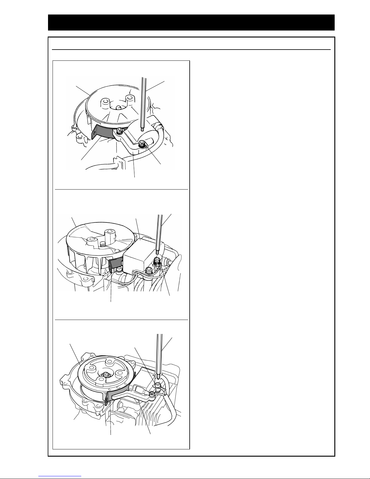
4-16 Cable Wiring
Switch Cord Wiring HB23 Series, HBZ26 Series
● Insert the grommet to align with the volute case
notch and clamp the cord between the protrusions
as shown in the figure at left.
Check that the cord on the module side is not
caught between volute case and crankcase.
● Pay attention that the cord is not caught against the
engine cover when it is installed.
Switch Cord Wiring EBZ30 Series
● Align the cord along the guide, and insert the
grommet to align with the volute case notch.
Check that the cord on the module side is not
caught between volute case and crankcase.
● Set the lead cords and clamp them as shown in the
figure at left.
Align the cord not to interfere with the clamp
mounting screw.
● Pay attention that the cord is not caught against the
engine cover when it is installed.
High Tension Cord Wiring EB4300/ 6200, EB70 Series, EBZ4800, EBZ51/ 71/ 80 Series
Insert the grommet to align with the crankcase's notch
and align the high tension cord and secure it with the
clamp as shown in the figure at left.
Align the high tension cord not to interfere
with the crankcase or the clamp mounting
screw.
CAUTION
CAUTION
CAUTION
CAUTION
Cords
Grommet
Cords
Grommet
Cord
Clamp
Crankcase
Clamp
Grommet
High Tension
Cord
Page 39

31
4. Service Guide
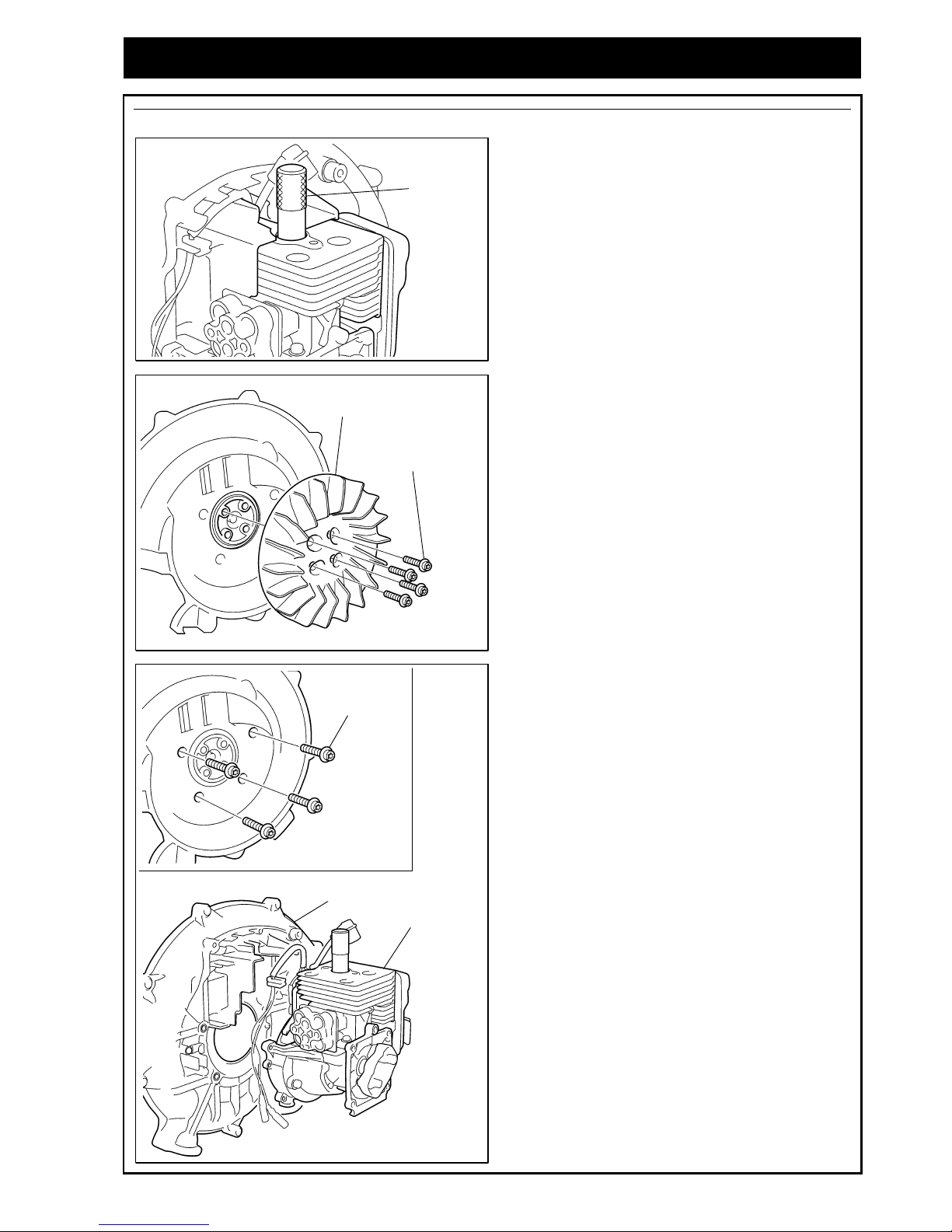
4-17 Fan Assembly
All Models
● Insert the stopper (special tool) into the plug hole
(refer to “3 Special Tool”).
● Tighten the mounting nut so that the fan securely
meets the rotor without looseness.
If the fan is installed with four mounting
bolts, secure them with equal pressure in
diagonal order.
4-18 Backpack Pad Air Supply Pipe Assembly
EB4300/ 6200, EB70 Series, EBZ4800, EBZ51/ 71 Series
Firmly insert the tip of the air supply nozzle into the
frame air inlet pipe.
4-19 Upper Spring Damper Assembly
EBZ30 Series
Reassembly of the upper spring damper is the reverse
procedure of disassembly.
Refer to "4-3 Upper Spring Damper Removal".
Check that the each spring edge is firmly
mated with the volute cover and spring
holder's groove.
CAUTION
CAUTION
Fan
Mounting Nut
Torque:
9.8~14.7N・m
(100~150kgf・cm)
Mounting Bolt
Torque:
7.8~11.8N・m
(80~120kgf・cm)
Fan
【【【【HB23/ 26 Series】】】】
1
2
3
4
Frame
Nozzle
Pipe
Volute Cover
Spring Holder
Page 40

32
4. Service Guide
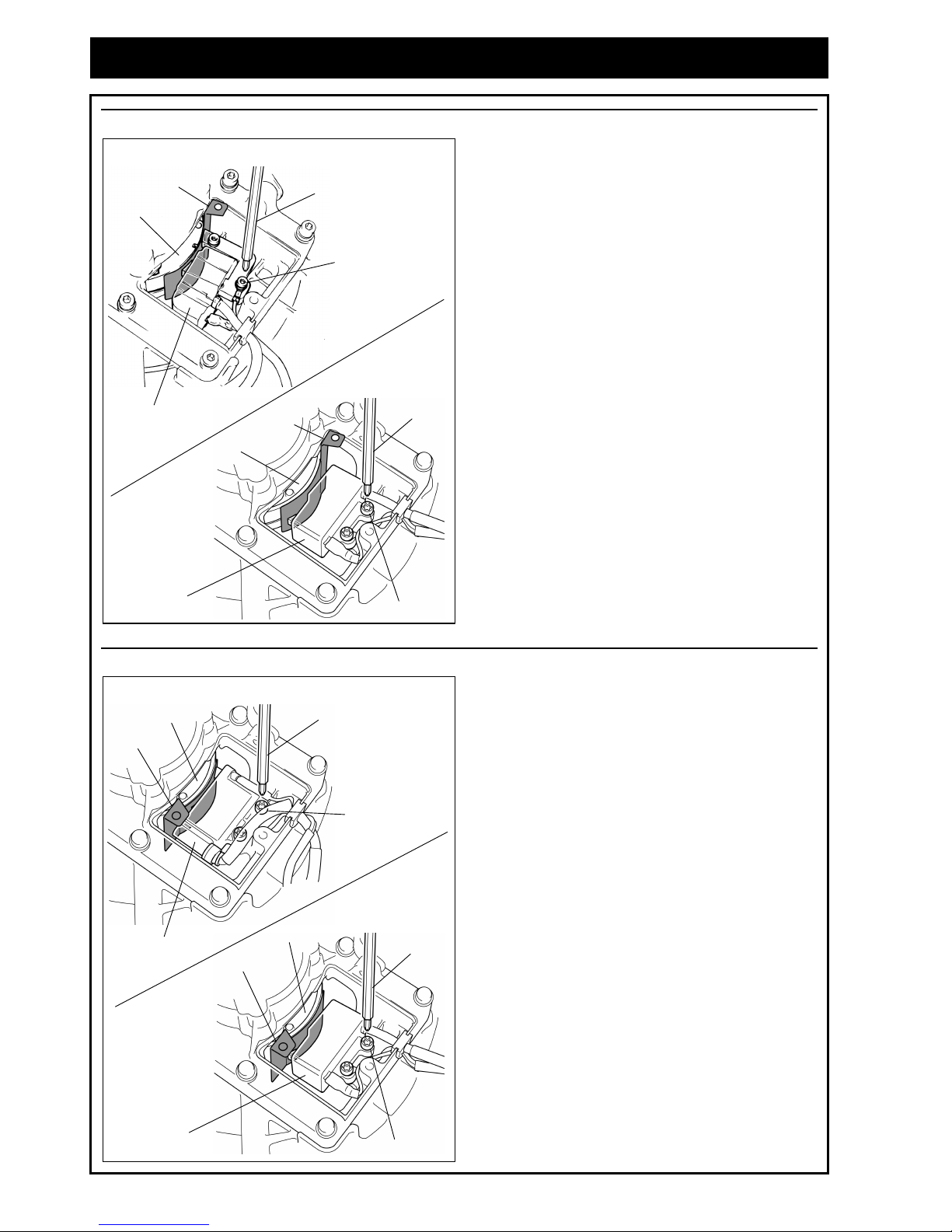
4-20 Upper Damper Assembly
EB4300/6200, EB70 Series, EBZ4800, EBZ51/ 71/ 80 Series
Assemble the damper and volute cover by mating
their protrusions.
Check that the damper is not tilted. Improper
installation will result in rapid damage.
4-21 Lower Damper Assembly
EB4300/6200, EB70 Series, EBZ4800, EBZ51/ 71/ 80 Series
Grip the damper's metal flange with the pliers in order
not to twist the rubber unit and tighten the mounting
nut with a wrench.
CAUTION
Vibration
Proof
Damper
Pliers
Mounting Nut
Wrench
Damper
Volute Cover
Volute Cover Protrusion
Damper Protrusion
Page 41
33
4. Service Guide
4-22 Carburetor Assembly
EBZ71/ 80 Series
Tighten the screws of the earth cord between the
carburetor's adjuster unit and the crankcase.
This cord prevents electrostatic sparks.
Do not fail to connect it.
4-23 Engine Cover Assembly
Check of the Gasket Assembly HB23 Series
When the engine cover is installed, pay attention to
installing the muffler’s gasket to the inside the cover to
protect the fuel tank from heat.
Check of the Gasket Assembly HBZ26 Series
When the engine cover is installed, pay attention to
installing the insulator gasket to the inside of the cover
to protect the carburetor from heat.
CAUTION
Carburetor
Earth Cord
Engine Cover
Fuel Tank
Muffler Gasket
Engine Cover
Carburetor
Insulator Gasket
Page 42

34
4. Service Guide
4-24 Check of the Gasket Assembly
EBZ4800, EBZ51/ 71/ 80 Series
Check that the master and insulator gaskets are set
inside the cylinder plate before the engine cover is
installed.
If the gasket is improperly set, engine cooling
performance will be reduced.
EB4300/ 6200, EB70 Series
Check that the master gasket is set outside of the
cylinder plate and the insulator gasket is set inside the
volute case before the engine cover is installed.
If the gasket is improperly set, engine cooling
performance will be reduced.
CAUTION
CAUTION
Cylinder Plate
Insulator Gasket
Muffler Gasket
【【【【Intake Side】】】】 【【【【Exhaust Side】】】】
Cylinder Plate
Cylinder Plate
Insulator Gasket
Muffler Gasket
Volute Case
【【【【
Intake Side
】】】】
【【【【
Exhaust Side
】】】】
Page 43

35
4. Service Guide
Husqvarna Zenoah engine blowers are equipped with spark arresters to prevent spark dispersion.
・・・・ The Spark arrester prevents burnt carbon discharging from the muffler.
Even though the spark arrester can easily clog with carbon, never operate the blower with the
spark arrester detached.
・・・・ The EB4300 and EBZ4800 (Japanese specifications) are not equipped with spark arresters.
4-25 Spark Arrester Removal
HB23 Series, HBZ26 Series
1. Remove the engine cover.
(Refer to “3. Special Tools”)
2. Remove the two mounting bolts and then remove
the muffler.
Torque:
HB23 Series: 6.9~9.8N・m (70~100kgf・cm)
HBZ26 Series: 6.9~10.8N・m (70~110kgf・cm)
3. Remove the spark arrester.
EBZ30 Series
1. Remove the engine cover.
(Refer to “3. Special Tools”)
2. Remove the two mounting bolts and then remove
the muffler.
Torque: 6.9~10.8N・m (70~110kgf・cm)
3. Remove the two mounting bolts (torx) and then
attach the diffuser (diffusing cover).
Torque: 2~3N・m (20~30kgf・cm)
4. Remove the spark arrester.
EB4300/ 6200, EB70 Series
1. Remove the engine cover.
(Refer to “3. Special Tools”)
2. Remove the three mounting bolts and then remove
the muffler.
Torque: 7.8~11 .8N・m (80~120kgf・cm)
3. Remove the spark arrester.
CAUTION
Spark Arrester
Mounting Bolt
×2
Muffler
Spark Arrester
Mounting Bolt
×2
Muffler
Mounting Bolt
×2
Diffuser
Spark Arrester
Mounting Bolt (long)
×2
Muffler
Mounting Bolt (short)
Page 44

36
4. Service Guide
EBZ51/ 71/ 80 Series
1. Remove the engine cover.
(Refer to “3. Special Tools”)
2. Remove the three mounting bolts and then remove
the muffler.
Torque: 7.8~11 .8N・m (80~120kgf・cm)
3. Remove the four mounting bolts (torx) and then
attach the diffuser (diffusing cover) and the spark
arrester.
Torque: 2~3N・m (20~30kgf・cm)
4-26 Spark Arrester Cleaning
Exceptions for EB4300, EBZ4800 (Japanese specifications)
Remove any carbon slag adhering to the spark
arrester (screen) with a brush, preferably wire-type or
equivalent.
Never overheat the spark arrester with a gas
torch or other flame. The spark arrester may
deform with heat.
4-27 Muffler Cleaning
All Models
Insert a screwdriver into the vent, and wipe away any
carbon buildup. Wipe away any carbon buildup on the
muffler exhaust vent and cylinder exhaust port at the
same time.
CAUTION
Spark Arrester
Mounting Bolt (long)
×2
Muffler
Mounting Bolt
×4
Diffuser
Mounting Bolt (short)
Spark Arrester
Spark Arrester
Screwdriver
Muffler
Page 45

37
4. Service Guide
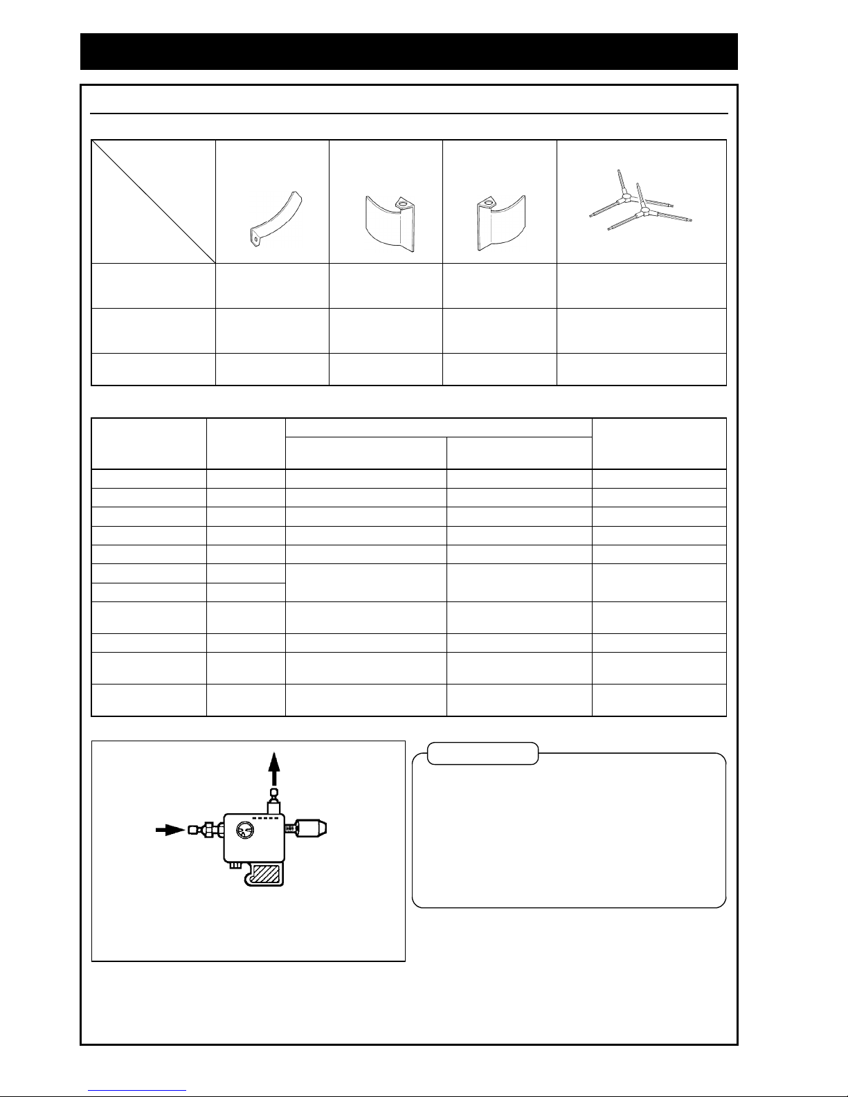
4-28 Air Cleaner Inspection
This device blows fallen leaves to a collection point but at the same time small particles (dust and sand)
become airborne. If such dust invades the engine, the engine mechanism will wear quickly.
So periodically check and clean the element according to the following table.
・・・・ The power blower operating environment is very dusty so the air cleaner will clog more
quickly than that of other power tools. Neglecting air cleaner check and maintenance will
cause rapid engine wear and poor engine performance.
・・・・ The urethane element may deteriorate and crumble if the ambient temperature fluctuates
greatly. If temperature related engine trouble is observed, resolve the trouble cause then
replace the filter with a new one.
Inspection Period
Operating Hours
Inspection Item
Daily 25 hours 50 hours 100 hours
Remarks
Element ○△ ☆
Pre-filter ○△ ☆
If this material is damaged, deformed, or aged and
crumbling, replace it with a new one.
(Annual replacement is recommended.)
Paper Filter ○△ ○△☆
If this filter is cleaned six times or more before the
replacement interval arrives, the paper part darkens
or water or oil adheres, replace it with a new one.
(Annual replacement is recommended)
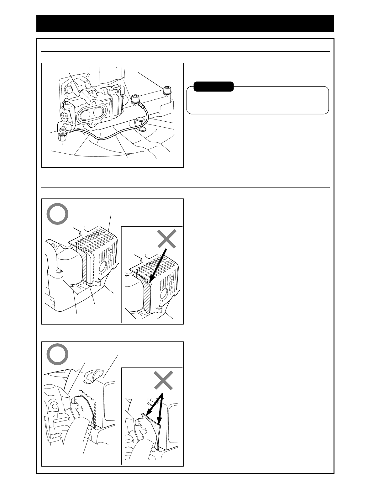
○: Inspection △: Clean ☆: Replace
4-29 Element Removal
Single layer dry urethane foam HB23 Series
Remove the cover while pressing the clip. Remove
the two elements.
Single layer dry urethane foam HBZ26 Series, EBZ30 Series
Loosen the knob then remove the element.
CAUTION
Silencer
Cover
Elements
Screen
Plate
Clip
Cover
Element
Screen
Packing
Knob
Knob
Page 46

38
4. Service Guide
Single layer half-wet urethane foam EB4300/ 6200
Loosen the knob then remove the element.
Dual layer half-wet urethane foam EBZ4800
Loosen the knobs then remove the elements.
Single layer half-wet urethane foam EBZ51 Series
Loosen the knobs then remove the element.
Two stage dry element (Pre-filter + Paper filter) EB70 Series, EBZ71 Series
Loosen the knob bolts then remove the element
(pre-filter + paper filter).
Cover
Element
Screen
Screw
Knob
Knob
Cover
Elements
Yellow Black
Screen
Knobs
Knobs
Packing
Cover
Element
Screen
Knobs
Knobs
Packing
Cover
Pre-filter
Knob Bolts
Paper Filter
Page 47

39
4. Service Guide
Two stage dry element (Pre-filter + Paper filter) EBZ80 Series
Loosen the knob bolts then remove the element
(pre-filter + paper filter).
4-30 Element Cleaning
Element and pre-filter rinsing All Models
● Rinse the element carefully with warm water diluted
detergent or washing oil.
Confirm that no deformity, damage or
deterioration (if touched, element will
crumble) exists.
If necessary replace it with a new one.
● After rinsing it, tighten squeeze the element to
remove moisture.
● For a HB23 series and HBZ26 series element or a
EB70 series and EBZ71/ 80 series pre-filter, dry it
after rinsing and then install it.
Caution for element installation EB4300/ 6200, EBZ4800, EBZ51 Series
The half-wet urethane element should be moistened
with 2-cycle engine oil, softly squeezed, then installed.
・・・・ Excessive oil adhesion will cause filter
clogging.
・・・・ Never moisten pre-filter (EB70 series and
EBZ71/80 series) with engine oil.
If engine oil adheres to the filter, the paper
layer will not function.
Two stage dry paper filter cleaning EB70 Series, EBZ71/ 80 Series
Blow compressed air from inside/outside of the filter
along the filter element's pleats.
Never beat or hit the filter.
CAUTION
CAUTION
CAUTION
Cover
Pre-filter
Knob Bolts
Case
Paper Filter
Warm water diluted
detergent or washing oil
2-cycle engine oil
Page 48

40
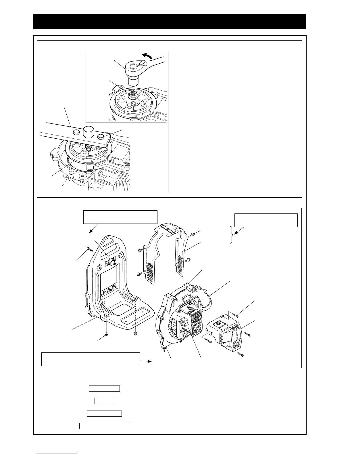
5. Structure of Right Hand Throttle Lever
● The right hand throttle lever specifications (RH) employs a governor mechanism for easy blower operation
with constant wind pressure.
Throttle Lever
Throttle Lock Lever
Light Handle
<Configuration>
The throttle lock lever is fixed by plate spring
pressure.
If the plate spring pressure decreases over its
operational life, the throttle lever will lose its
locking function.
If plate spring pressure decreases, replace it
with a new one.
Throttle lever
Throttle Lock Lever
Height: 1.42 to 1.65 mm
(0.056 to 0.065 in.)
Snap Ring
Washer
Spring Washer
Washer
Shaft
<Caution in switch cord installation>
Thread the switch cord into the handle case slit and set its terminal 90 to 100 mm (3.54 to 3.94 in.) from the end of the
slit.
* Confirm that the switch cord remains slack when the switch is moved.
90 to 100 mm
(3.54 to 3.94 in.)
Slacken cord.
Switch Cord
<Governor Mechanism>
It is a mechanism where the throttle lever can be fixed by
a throttle lever lock at a chosen position.
The suitable engine speed can be set for operating load.
Throttle Lever Functional State
Throttle Lever Locked State
Throttle lever's
protrusion
Throttle lock lever's protrusion
Throttle lever
functional area
Throttle lever
locking area
Page 49

Page 50

41
6. Carburetor
6-1 Specifications
Model Carburetor (Walbro) Carburetor Specifications
Seal (L-needle)
Sales Region
Blower
Model
Engine
Type
Type
Name
Part
Number
Part Name Part Number
Adjustment angle
(L-needle return
angle)
Adjustment angle
(H-needle return
angle)
Main Jet
Venturi Bore
(Lead Air)
mm (in.)
Venturi Bore
(Mixture Air)
mm (in.)
Choke Bore
mm (in.)
Metering Lever
Height
mm (in.)
Valve Opening
Pressure
kg/ cm
2
(kpa)
Valve Closing
Pressure
kg/ cm
2
(kpa)
EU/ General HB2302 G23L
WYJ-110A 5516-81000 Limiter Cap 848-F40-80D0 Adjustment FIXED # 38
―
9 (0.354) 17 (0.669)
1.5±0.16
(0.059±0.006)
1.3~2.3 0.6~1.6
EU/ General HBZ2601 GZ25N W YA-26E 848-F3C-8102 ↑ ↑ ↑ ↑ # 37.5 8 (0.315) 9 (0.354) 13.2 (0.520) ↑ ↑ ↑
USA HBZ2601
↑↑↑↑ WYA-65 848-F3U-8100 ↑ ↑ ↑ 1 3/4±1/2
―
9 (0.354) 7 (0.276) 13.2 (0.520) ↑ ↑ ↑
USA/ EU/
General
EBZ3000/ RH GZ30N W YA-73B 848-F6B-8101 ↑ ↑ ↑ FIXED # 34 9 (0.354) 7 (0.276) 13.2 (0.520) ↑ ↑ ↑
General EB4300 G4K
WYK-67A 3407-81000 ↑ ↑ ↑ ↑ # 60
―
13.5 17 (0.669) ↑ ↑ ↑
EU/ General EBZ4800 GZ48N WYA-51B 848-L38-8100 ↑ ↑ ↑ ↑ # 45 10.5 (0.413) 10.5 (0.413) 14.5 (0.571) ↑ ↑ ↑
GZ51N3.5
WYA-74A 848-HE0-8100
USA EBZ5100/ RH
GZ51N6
WYA-79 848-HE2-8100
↑ ↑ ↑ ↑ # 44 10.5 (0.413) 10.5 (0.413) 14.5 (0.571) ↑ ↑ ↑
USA EBZ5100Q GZ51N7 WYA-83 848-HE6-8100 ↑ ↑ ↑ ↑ # 41.5 10.5 (0.413) 10.5 (0.413) 14.5 (0.571) ↑ ↑ ↑
General EB6200 G62L
WYK-73A 2750-81000 ↑ ↑ ↑ ↑ # 59
―
15 (0.591) 17 (0.669) ↑ ↑ ↑
EU/ General EB7000 ↑↑↑↑ W YK-123A T4012-81000 ↑ ↑ ↑ ↑ # 53
―
15 (0.591) 17 (0.669) ↑ ↑ ↑
USA EBZ7100/ RH GZ65N
WYA-81 848-H18-8100 ↑ ↑ ↑ ↑ # 57 13.5 (0.532) 12.2 (0.480) 14.5 (0.571) ↑ ↑ ↑
USA/ EU/
General
EBZ8001/ RH GZ72N W YA-44B 848-H00-8100 ↑ ↑ ↑ ↑ # 59 13. 5 (0.532) 12.2 (0.480) 14.5 (0.571) ↑ ↑ ↑
Model
Adjustment Angle for Engine Start
(Loosen then tighten)
Engine Speed (rpm) Standard Engine Speed (rpm)
Sales Region
Blower
Model
Engine
Type
Throttle
Valve Adjust
Screw
L-needle
Adjustmen t
Angle
H-needle
Adjustmen t
Angle
ID Peak
Engine
Speed
ID Rich
Down
Set ID
Engine
Speed
H Rich
Down
Set H
Engine
Speed
Idling
Full Throttle
(Standard Pipe)
Remarks Recommended Tools
EU/ General HB2302 G23L
9 13 FIXED 3400±10 1000~1200 2300±100 FIX JET FIX JET 2300±200 7300~7600
EU/ General HBZ2601 GZ25N 8 1/2 12 1/2 ↑ 3700±10 800~1000 2800±100 ↑ ↑ 2800±200 7700~7990
USA HBZ2601
↑↑↑↑ 8 1/2 13 1/2 1 7/8 3900±10 1000~1200 2800±100 50~100 7300 2800±200 7300~7800
USA/ EU/
General
EBZ3000/ RH GZ30N 8 1/2 12 FIXED 3500±10 400~100 3000±100 FIX JET FIX JET 3000±200 6300~6800
General EB4300 G4K
4 1/2 10 1/2 ↑ 2700±10 600~800 2000±100 ↑ ↑ 2000±200 6150~6550
EU/ General EBZ4800 GZ48N 11 1/2 9 ↑ 3400±10 1000~1200 ↑ ↑ ↑ ↑ ↑
GZ51N3.5
9 11 1/2 3000±10 700~900
USA EBZ5100/ RH
GZ51N6
6 10
↑
2900±10 600~800
2200±100 ↑ ↑ 2200±200 5820~6100
Digital magneto controlled misfire
for excessive speed
Maximum speed: 8500 rpm
USA EBZ5100Q GZ51N7 3 1/2 10 ↑ 2900±10 600~800 2200±100 ↑ ↑ 2200±200 5520~5800
General EB6200 G62L
4 10 1/2 ↑ 2500±10 400~600 2000±100 ↑ ↑ 2000±200 7500~7800
EU/ General EB7000 ↑↑↑↑ 7 10 1/2 ↑ 2700±10 600~800 ↑ ↑ ↑ ↑ 7100~7500
USA EBZ7100/ RH GZ65N
7 12 ↑ 2700±10 600~800 2000±100 ↑ ↑ 2000±200 6850~7150
Digital magneto controlled misfire
for excessive speed
Maximum speed: 8500 rpm
USA/ EU/
General
EBZ8001/ RH GZ72N 6 1/2 12 ↑ 2700±10 600~800 2000±100 ↑ ↑ 2000±200 6500~6800
Digital magneto controlled misfire
for excessive speed
Maximum speed: 8500 rpm
① 3699-90345
Carburetor Conditioner
④ 848-8W9-0080
Limiter Cap Tool
② 3699-90211
Leak Tester
③ 3699-90537
Tachometer PET-1000
Page 51

42
6. Carburetor
6-2 Carburetor Configuration
Inspection and adjustment items
Execute the following check and adjustment if the carburetor does not function normally.
(Refer to "6-5 Idling Speed Adjustment " and "6-6 Carburetor Inspection".)
● Fuel adjustment when idling
● Check of the body assembly
● Check of the main check valve
● Check of throttle valve
Readjust the engine rotational speed referring to "6-7 Carburetor Adjustment"
if the engine speed is not steady after the above-mentioned adjustment and the checks are executed.
L-needle
Construction
【【【【Type: W Y J 】】】】 【【【【Type: W YA】】】】
Main Jet
Main Check Valve
Body Assembly
Inlet Valve
Main Diaphragm
Metering Lever
Screen
L- needle
Main Jet
Main Check Valve
Body Assembly
Inlet Valve
Main Diaphragm
Metering Lever
Screen
H-needle
【【【【
USA/ HBZ2601 only
】】】】
Throttle Valve Assembly
Throttle Valve Assembly
Page 52

43
6. Carburetor
6-3 Carburetor Conforms to Exhaust Emissions Regulations
The carburetor flow rates of all Hasqvarna Zenoah engine blowers are individually pre-adjusted to pass
exhaust emissions regulations.
A limiter cap is installed in the idling limiter to prevent an operator carelessly changing the idle setting resulting
in non-conformance with exhaust emission regulations.
Execute a correct adjustment according to "6-7 Carburetor Adjustment".
A limiter cap closes the L-needle adjustment hole of
the throttle valve.
Carburetor adjustments with caps removed must be conducted by Emission Certified
Servicing Dealers ONLY.
The dealer must supply the unit to the customer in original configuration, using the
manufacturer’s
carburetor adjustment procedure, which includes having the limiter caps in
place before the unit is put into service.
Knowingly removing or rendering inoperative any device, element, or design installed on or in
a non-road engine which is in compliance with E. P. A. or C. A. R. B. (USA), STAGEⅢⅢⅢⅢ(EU)
regulations is classified as TAMPERING.
TAMPERING is a violation of FEDERAL LOW, resulting in significant civil penalties (fines) of up
to $25,000 for each violation.
ATTENTION!!! IMPORTANT!!!
L-needle
Limiter Cap
Throttle Valve
Page 53

44
6. Carburetor
6-4 Limiter Cap Removal/ Installation
Tool
The limiter cap tool (carburetor maintenance tool:
848-8W9-0080) is used for limiter cap
installation/removal.
Removal
Insert the limiter cap tool extraction tool's threading
(M2 counterclockwise threading) into the idling
limiter's hole and screw it counterclockwise while
giving pressure.
When it is firmly threaded, pull the limiter cap.
If it is difficult to screw in the limiter cap tool,
firmly press the tool while screwing. When
threads are completely meshed, pull it out in
one stroke. If cap is damaged and stays in
the hole, use a pick type tool to remove it.
Installation
Insert a new limiter cap in the low speed mixture
needle hole. Press the cap deeply into low speed
mixture needle hole to prevent tampering.
Be sure to install only a new limiter cap.
The limiter cap is a very small part. Pay
attention not to lose it.
6-5 Idling Speed Adjustment
Slow and Middle Speeds All Models
Adjust the fuel supply under idling conditions by turning the idling limiter.
1. Remove the limiter cap.
(Refer to "6-4 Limiter Cap Removal/ Installation".)
After completion of the adjustment, be sure
to install the limiter cap.
2. Turn the screw with a commercially available screw
driver (tip width: 2.5mm).
Clockwise (CW):
Fuel mixture becomes lean. (Speed increases.)
Counterclockwise (CCW):
Fuel mixture becomes rich. (Speed decreases.)
CAUTION
CAUTION
Limiter cap insertion side
Limiter cap
(new part)
CAUTION
Screw Driver
Increases Decreases
Limiter cap insertion side
Limiter cap tool extraction side
Screw unit
(M2 counterclockwise threading)
Limiter Cap Tool
Limiter Cap
Limiter cap tool extraction side
Press it while turning it
counterclockwise.
Pull it out.
Limiter cap is
removed.
Page 54

45
6. Carburetor
High Speed Adjustment 【【【【USA/ HBZ2601 only】】】】
High speed revolutions are adjusted by a H-needle.
Clockwise (CW):
Fuel mixture becomes lean. (Speed increases.)
Counterclockwise (CCW):
Fuel mixture becomes rich. (Speed decreases.)
6-6 Carburetor Inspection
Inlet Valve Leaking Test
Connect a leak tester to the fuel inlet port of the carburetor.
After filling the metering chamber with fuel, apply pressure to the inlet valve and read the opening pressure
and the reseating pressure.
a. Body assembly normality check
● Measure the metering lever height using a depth
gauge or scale.
The appropriate value is 1.5±0.16 mm (0.059±
0.006 in.)
● Check that no wear exists on the metering lever or
diaphragm contacting areas.
If wear exists, replace it with a new one.
● Remove the inlet valve and check for dirt, sludge,
rusting and/or step-wear.
Replace the inlet valve if a step is found on the
rubber tip.
● Check that no alien matter adheres to the valve
sheet part. If any alien matter exists, dip the valve
sheet in gasoline for about 10 minutes and remove
it, or use the carburetor conditioner (Carburetor
Conditioner: 699-90345) to clean it.
● Check that no alien matter has accumulated on the
screen.
If screen is clogged with alien matter, remove the
screen and clean it.
H-needle
Increases
Decreases
Metering Lever
Inlet Valve
Rubber Tip
1.5±0.16 mm
(0.059±0.006 in.)
Body
Assembly
Metering Lever
Main Diaphragm
Valve Sheet
Screen
Body Assembly
Page 55

46
6. Carburetor
b. Judgments of the main check valve
● As illustrated, hold a plastic pipe on the check
valve and blow and suck air by your mouth. If the
air is stopped by blowing, and open by sucking, the
valve has no failure.
● In case of failure, soak the valve into gasoline for
about 10 minutes and repeat blowing and sucking
several times.
If this is not successful, replace the body assembly.
● Make sure to check the valve in case fuel is not
supplied though the priming pump is operated.
c. Throttle valve normality check
● Check that no wear exists in the throttle valve slide.
Carefully slide a screw driver tip along the plunger's
contact surface.
If the screw driver tip catches in a groove, replace
the carburetor assembly with a new one.
● Check that no wear exists on the jet needle.
If there are signs of vertical linear flaws or wear,
replace the carburetor assembly with a new one.
Even small damage will increase fuel
consumption.
Plunger
Throttle Valve Assembly
Contact Surface
CAUTION
Jet Needle Portion
Damage Wear
Plastic Pipe
Main Check Valve
Body Assembly
Page 56

47
6. Carburetor
6-7 Carburetor Adjustment
Before performing carburetor adjustment, the following areas must be inspected for good
working order.
● Correct spark plug set to specified gap must be installed.
● The air filter and paper filter must be clean and properly installed.
● The muffler spark arrestor screen and exhaust port must be clear of carbon.
● The fuel filter must be clean and properly installed.
● The carburetor and carburetor insulator block screw must be tight.
● The fuel must be fresh (properly mixed at 40:1 ratio with Zenoah or 50:1 ratio with RedMax)
● All standard air tubes (Air Pipes) must be installed.
● No fallen leaf or other matter must be adhered to the air intake.
Required Tools and Parts
● Carburetor adjustment screw driver 2.5mm flat tip
● Electronic digital tachometer
● Limiter cap removal tool
● New Limiter cap
Adjustment when engine activated
1. Start the engine and alternate three times between
the idling state (10 seconds) and full throttle state
(60 seconds). Then check the engine's condition.
2. If idling is not stable, remove the limiter cap (refer
to "6-4 Limiter Cap Removal/ Installation") and
adjust the engine according to the following
procedure.
● Throttle valve adjust screw
Clockwise (CW) 1&1/2 turn:
Increases engine speed.
● L-needle
Counterclockwise (CCW) 1/8 turn:
Enriches the fuel mixture.
(Reduces engine speed.)
● H-needle 【【【【USA/ HBZ2601 only】】】】
Counterclockwise (CCW) 1/8 turn:
Reduces engine speed.
3. Run the warm-up operation (see the above table)
and execute the rich down adjustment.
(Refer to "Rich Down Adjustment".)
Throttle Valve
Adjust Screw
1&1/2 turn
L-needle
1/8 turn
H-needle
【【【【USA/ HBZ2601 only】】】】
1/8 turn
Idling
Full
Throttle
1st Time 2nd Time 3rd Time
Page 57

48
6. Carburetor
Adjustment if engine does not activate
Set the adjustable parts as specified according to the
following procedure.
1. Loosen the throttle valve adjust screw until the
throttle valve becomes completely free, then turn
the screw clockwise until the regulated angle is
attained.
(Refer to "6-1 Specifications- Adjustment Angle for
Engine Start".)
2. Turn the idling limiter (L-needle) counterclockwise
until it becomes free. (When the needle screw
completely loosens, a click tone can be heard.)
Turn the idling limiter clockwise from this position
until the regulated angle is attained.
(Refer to "6-1 Specifications- Adjustment Angle for
Engine Start- L-needle Adjustment Angle".)
When tightening the L-needle clockwise,
never excessively tighten it.
Doing so may cause damage to the needle
surface resulting in excessive or inconsistent
fuel supply.
3. H-needle 【【【【USA/ HBZ2601 only】】】】
Clockwise (CW) completely, then back it off 1&7/8
turns counterclockwise (CCW).
4. Start the engine and execute the rich down
adjustment. (Refer to "Rich Down Adjustment".)
If the engine still does not start, problems
may exist elsewhere than the carburetor.
Check those other causes.
CAUTION
CAUTION
Throttle Valve
Adjust Screw
L-needle
H-needle
【【【【USA/ HBZ2601 only】】】】
Page 58

49
6. Carburetor
Rich Down Adjustment
1. Turn the idling limiter (L-needle) clockwise to the
position of maximum engine speed.
2. Turn the throttle valve adjust screw in either
direction to match to the regulated ID peak speed.
(Refer to "6-1 Specifications- ID Peak Engine
Speed".)
3. Turn the L-needle counterclockwise and execute
the rich down adjustment.
(Refer to "6-1 Specifications- ID Rich Down".)
4. Turn the throttle valve adjust screw in either
direction and set the ID speed.
(Refer to "6-1 Specifications- Set ID Engine
Speed".)
5. Check that rotational speed accelerates normally
between idling state and full throttle within the
regulated number of revolutions.
(Refer to "6-1 Specifications- Standard Engine
Speed".)
【【【【USA/ HBZ2601 only】】】】
After the above adjustment is completed, adjust the
H-needle.
1. Turn the H-needle clockwise so that the speed
reaches its peak (7300 to 7800 rpm).
2. When the speed reaches its peak, turn the
H-needle counterclockwise until the speed falls 50
to 100 rpm. (Set H Engine Speed: 7300 rpm)
The HBZ2601 rich down procedure might not
optimize the L-needle and H-needle
relationship at first try.
If so repeat this procedure twice.
Throttle Valve
Adjust Screw
L-needle
H-needle
Rich Down:
Adjust the idle needle to a slightly richer mixture in order
to maintain a stable idling speed and get a good
acceleration.
Peak engine speed
Set engine speed
Peak
Rich Down
Best
Consumption (ℓ/h)
(rpm)
REFERENCE
Page 59

50
6. Carburetor
Confirmation after adjustment
● After adjustment is completed, be sure to install the
new limiter cap.
(Refer to "6-4 Limiter Cap Removal/ Installation".)
● Be sure to reattach the dust cover.
If the engine is run while the throttle valve's
dust cover is removed, dust or alien matter
may adhere to the throttle valve's rear
contoured or the plunger contacting
surfaces.
If they become worn, the L-needle will fall
causing engine start failure.
CAUTION
Dust Cover
Limiter Cap
Page 60

Page 61

51
7. Maintenance Standards
7-1 Engine
Maintenance Item Unit Specifications
Category ---- Handheld Blower Backpack Blower
Engine Type ---- G23L GZ25N GZ30N G4K GZ48N GZ51N G62L GZ65N GZ72N
HB2302
HB2311EZ
HBZ2601
EBZ3000/ 3000RH
EBZ3050RH
EB4300 EBZ4800
EBZ5100/ 5100RH/
5100Q
EBZ5150/ 5150RH/
5150Q
EB6200
EB7000
EB7001
EBZ7100/ 7100RH
EBZ7150/ 7150RH
EBZ8001/ 8001RH
EBZ8050/ 8050RH
Model
Blower Model ----
Standard Limit Standard Limit Standard Limit Standard Limit Standard Limit Standard Limit Standard Limit Standard Limit Standard Limit
Measuring
Instrument
Service
Procedure
Cylinder Bore mm (in.)
φ32.00
(1.2598)
φ32.06
(1.2622)
φ34.00
(1.3386)
φ34.06
(1.3409)
φ38.00
(1.4961)
φ38.06
(1.4984)
φ40.00
(1.5748)
φ40.06
(1.5772)
φ43.00
(1.6929)
φ43.06
(1.6953)
φ44.00
(1.7323)
φ44.06
(1.7346)
φ47.50
(1.8701)
φ47.56
(1.8724)
φ47.53
(1.8713)
φ47.59
(1.8736)
φ50.03
(1.9697)
φ50.09
(1.9720)
Cylinder Gauge
Replacement
(Plating Damaged
Replacement)
Piston Diameter
(Skirt)
mm (in.)
φ31.945
(1.2577)
~φ31.960
(1.2583)
φ31.86
(1.2543)
φ33.960
(1.3370)
~φ33.975
(1.3376)
φ33.86
(1.3331)
φ37.950
(1.4941)
~φ37.970
(1.4949)
φ37.86
(1.4906)
φ39.960
(1.5732)
~φ39.975
(1.5738)
φ39.87
(1.5697)
φ42.955
(1.6911)
~φ42.970
(1.6917)
φ42.87
(1.6878)
φ43.965
(1.7309)
~φ43.985
(1.7317)
φ43.88
(1.7276)
φ47.455
(1.8683)
~φ47.470
(1.8689)
φ47.37
(1.8650)
φ47.458
(1.8684)
~φ47.478
(1.8692)
φ47.37
(1.8650)
φ49.958
(1.9669)
~φ49.978
(1.9676)
φ49.87
(1.9634)
Micrometer Replacement
Top mm (in.)
1.51
(0.0594)
1.60
(0.0630)
1.03
(0.0406)
1.30
(0.0512)
1.23
(0.0484)
1.30
(0.0512)
1.57
(0.0618)
1.60
(0.0630)
1.25
(0.0492)
1.30
(0.0512)
1.25
(0.0492)
1.30
(0.0512)
1.55
(0.0610)
1.60
(0.0630)
1.25
(0.0492)
1.30
(0.0512)
1.25
(0.0492)
1.30
(0.0512)
Piston Ring
Groove Width
2nd mm (in.)
1.51
(0.0594)
1.60
(0.0630)
1.01
(0.0398)
1.30
(0.0512)
1.21
(0.0476)
1.30
(0.0512)
1.57
(0.0618)
1.60
(0.0630)
1.22
(0.0480)
1.30
(0.0512)
1.22
(0.0480)
1.30
(0.0512)
1.53
(0.0602)
1.60
(0.0630)
1.23
(0.0484)
1.30
(0.0512)
1.23
(0.0484)
1.30
(0.0512)
Thickness Gauge Replacement
Piston Pin Hole mm (in.)
φ7.990
(0.3146)
φ8.04
(0.3165)
φ7.995
(0.3148)
φ8.04
(0.3165)
φ8.995
(0.3541)
φ9.04
(0.3559)
φ10.995
(0.4329)
φ11.04
(0.4346)
φ10.995
(0.4329)
φ11.04
(0.4346)
φ10.995
(0.4329)
φ11.04
(0.4346)
φ10.995
(0.4329)
φ11.04
(0.4346)
φ11.995
(0.4722)
φ12.05
(0.4744)
φ11.995
(0.4722)
φ12.05
(0.4744)
Cylinder Gauge Replacement
Clearance Between
Piston and Cylinder
mm (in.)
0.040
(0.0016)
~0.080
(0.0031)
0.20
(0.0079)
0.025
(0.0010)
~0.065
(0.0026)
0.20
(0.0079)
0.030
(0.0012)
~0.075
(0.0030)
0.20
(0.0079)
0.025
(0.0010)
~0.065
(0.0026)
0.19
(0.0074)
0.030
(0.0012)
~0.070
(0.0028)
0.19
(0.0075)
0.015
(0.0006)
~0.060
(0.0024)
0.18
(0.0071)
0.030
(0.0012)
~0.065
(0.0026)
0.19
(0.0075)
0.052
(0.0020)
~0.092
(0.0036)
0.22
(0.0087)
0.052
(0.0020)
~0.092
(0.0036)
0.22
(0.0087)
Micrometer,
Cylinder Gauge
Piston
Replacement
Top mm (in.)
0.02
(0.0008)
~0.06
(0.0024)
0.10
(0.0039)
0.04
(0.0016)
~0.08
(0.0031)
0.10
(0.0039)
0.04
(0.0016)
~0.08
(0.0031)
0.10
(0.0039)
0.08
(0.0031)
~0.12
(0.0047)
0.15
(0.0059)
0.06
(0.0024)
~0.10
(0.0039)
0.15
(0.0059)
0.06
(0.0024)
~0.10
(0.0039)
0.15
(0.0059)
0.06
(0.0024)
~0.10
(0.0039)
0.15
(0.0059)
0.06
(0.0024)
~0.10
(0.0039)
0.15
(0.0059)
0.06
(0.0024)
~0.10
(0.0039)
0.15
(0.0059)
Clearance
Between
Piston
Groove and
Piston Ring
2nd mm (in.)
0.02
(0.0008)
~0.06
(0.0024)
0.10
(0.0039)
0.02
(0.0008)
~0.06
(0.0024)
0.10
(0.0039)
0.02
(0.0008)
~0.06
(0.0024)
0.10
(0.0039)
0.08
(0.0031)
~0.12
(0.0047)
0.15
(0.0059)
0.03
(0.0012)
~0.07
(0.0028)
0.15
(0.0059)
0.03
(0.0012)
~0.07
(0.0028)
0.15
(0.0059)
0.04
(0.0016)
~0.08
(0.0031)
0.15
(0.0059)
0.04
(0.0016)
~0.08
(0.0031)
0.15
(0.0059)
0.04
(0.0016)
~0.08
(0.0031)
0.15
(0.0059)
Thickness Gauge Replacement
Piston
Fitting Between
Piston Pin and
Piston Pin Hole
mm (in.)
0.010T
(0.00039T)
~0.006L
(0.00024L)
0.06L
(0.00024L)
0.005T
(0.00020T)
~0.011L
(0.00043L)
0.06L
(0.00024L)
0.005T
(0.00020T)
~0.011L
(0.00043L)
0.06L
(0.00024L)
0.005T
(0.00020T)
~0.011L
(0.00043L)
0.06L
(0.00024L)
0.005L
(0.00020T)
~0.021L
(0.00083L)
0.06L
(0.00024L)
0.005L
(0.00020T)
~0.021L
(0.00083L)
0.06L
(0.00024L)
0.005L
(0.00020T)
~0.021L
(0.00083L)
0.06L
(0.00024L)
0.005L
(0.00020T)
~0.021L
(0.00083L)
0.07L
(0.0028L)
0.005L
(0.00020T)
~0.021L
(0.00083L)
0.07L
(0.0028L)
Micrometer,
Cylinder Gauge
Replacement
End Gap at Cylinder
Skirt
mm (in.)
0.10
(0.0039)
~0.30
(0.0118)
0.50
(0.0197)
0.10
(0.0039)
~0.30
(0.0118)
0.50
(0.0197)
0.10
(0.0039)
~0.30
(0.0118)
0.50
(0.0197)
0.10
(0.0039)
~0.30
(0.0118)
0.50
(0.0197)
0.10
(0.0039)
~0.30
(0.0118)
0.50
(0.0197)
0.10
(0.0039)
~0.30
(0.0118)
0.50
(0.0197)
0.15
(0.0059)
~0.35
(0.0138)
0.6
(0.0236)
0.15
(0.0059)
~0.35
(0.0138)
0.6
(0.0236)
0.15
(0.0059)
~0.35
(0.0138)
0.6
(0.0236)
Thickness Gauge Replacement
Piston Ring
Width mm (in.)
1.5
(0.0591)
1.4
(0.0551)
1.0
(0.0394)
0.9
(0.0354)
1.2
(0.0472)
1.1
(0.0433)
1.5
(0.0591)
1.4
(0.0551)
1.2
(0.0472)
1.1
(0.0433)
1.2
(0.0472)
1.1
(0.0433)
1.5
(0.0591)
1.4
(0.0551)
1.2
(0.0472)
1.1
(0.0433)
1.2
(0.0472)
1.1
(0.0433)
Micrometer Replacement
Piston Pin Diameter mm (in.)
φ8.00
(0.3150)
φ7.98
(0.3142)
φ8.00
(0.3150)
φ7.98
(0.3142)
φ9.00
(0.3543)
φ8.98
(0.3535)
φ11.00
(0.4331)
φ10.98
(0.4323)
φ11.00
(0.4331)
φ10.98
(0.4323)
φ11.00
(0.4331)
φ10.98
(0.4323)
φ11.00
(0.4331)
φ10.98
(0.4323)
φ12.00
(0.4724)
φ11.98
(0.4717)
φ12.00
(0.4724)
φ11.98
(0.4717)
Micrometer Replacement
Small End Bore mm (in.)
φ11.00
(0.4331)
φ11.03
(0.4343)
φ11.00
(0.4331)
φ11.03
(0.4343)
φ12.00
(0.4724)
φ12.03
(0.4736)
φ15.00
(0.5906)
φ15.03
(0.5917)
φ15.00
(0.5906)
φ15.03
(0.5917)
φ15.00
(0.5906)
φ15.03
(0.5917)
φ15.00
(0.5906)
φ15.03
(0.5917)
φ16.00
(0.6299)
φ16.03
(0.6311)
φ16.00
(0.6299)
φ16.03
(0.6311)
Cylinder Gauge Replacement
Connecting
Rod
Parallelism of
Large/ Small End
Bores
-
0.15/ 100 - 0.15/ 100 - 0.15/ 100 - 0.15/ 100 - 0.15/ 100 - 0.15/ 100 - 0.15/ 100 - 0.15/ 100 - 0.15/ 100
Mandrel Dial
Gauge
Replacement
Diameter at Main
Bearing
mm (in.)
φ12.00
(0.4724)
φ11.97
(0.4713)
φ12.00
(0.4724)
φ11.97
(0.4713)
φ12.00
(0.4724)
φ11.97
(0.4713)
φ15.00
(0.5906)
φ14.95
(0.5886)
φ15.00
(0.5906)
φ14.95
(0.5886)
φ15.00
(0.5906)
φ14.95
(0.5886)
φ15.00
(0.5906)
φ14.95
(0.5886)
φ16.00
(0.6299)
φ15.95
(0.6280)
φ16.00
(0.6299)
φ15.95
(0.6280)
Micrometer Replacement
Crankshaft
(Starter
Side)
Diameter at Oil Seal mm (in.)
φ12.00
(0.4724)
φ11.90
(0.4685)
φ12.00
(0.4724)
φ11.90
(0.4685)
φ12.00
(0.4724)
φ11.90
(0.4685)
φ15.00
(0.5906)
φ14.90
(0.5866)
φ15.00
(0.5906)
φ14.90
(0.5866)
φ15.00
(0.5906)
φ14.90
(0.5866)
φ15.00
(0.5906)
φ14.90
(0.5866)
φ16.00
(0.6299)
φ15.90
(0.6260)
φ16.00
(0.6299)
φ15.90
(0.6260)
Micrometer Replacement
Diameter at Main
Bearing
mm (in.)
φ12.00
(0.4724)
φ11.97
(0.4713)
φ12.00
(0.4724)
φ11.97
(0.4713)
φ12.00
(0.4724)
φ11.97
(0.4713)
φ15.00
(0.5906)
φ14.95
(0.5886)
φ15.00
(0.5906)
φ14.95
(0.5886)
φ15.00
(0.5906)
φ14.95
(0.5886)
φ15.00
(0.5906)
φ14.95
(0.5886)
φ16.00
(0.6299)
φ15.95
(0.6280)
φ16.00
(0.6299)
φ15.95
(0.6280)
Micrometer Replacement
Crankshaft
(Fan Side)
Diameter at Oil Seal mm (in.)
φ12.00
(0.4724)
φ11.90
(0.4685)
φ12.00
(0.4724)
φ11.90
(0.4685)
φ12.00
(0.4724)
φ11.90
(0.4685)
φ15.00
(0.5906)
φ14.90
(0.5866)
φ15.00
(0.5906)
φ14.90
(0.5866)
φ15.00
(0.5906)
φ14.90
(0.5866)
φ15.00
(0.5906)
φ14.90
(0.5866)
φ16.00
(0.6299)
φ15.90
(0.6260)
φ16.00
(0.6299)
φ15.90
(0.6260)
Micrometer Replacement
Eccentricity mm (in.)
-
0.07
(0.0028)
-
0.07
(0.0028)
-
0.07
(0.0028)
-
0.07
(0.0028)
-
0.07
(0.0028)
-
0.07
(0.0028)
-
0.07
(0.0028)
-
0.07
(0.0028)
-
0.07
(0.0028)
Dial Gauge,
Center Support
Repair or
Replacement
Width Between
Crank Webs
mm (in.)
22.0
(0.8661)
21.9
(0.8622)
~22.1
(0.8701)
22.0
(0.8661)
21.9
(0.8622)
~22.1
(0.8701)
24.0
(0.9449)
23.9
(0.9409)
~24.1
(0.9488)
29.0
(1.1417)
28.9
(1.1378)
~29.1
(1.1457)
29.0
(1.1417)
28.9
(1.1378)
~29.1
(1.1457)
29.0
(1.1417)
28.9
(1.1378)
~29.1
(1.1457)
29.0
(1.1417)
28.9
(1.1378)
~29.1
(1.1457)
29.0
(1.1417)
28.9
(1.1378)
~29.1
(1.1457)
29.0
(1.1417)
28.9
(1.1378)
~29.1
(1.1457)
Micrometer
Repair or
Replacement
Crankshaft
Complete
Axial Play mm (in.)
-
0.5
(0.0197)
-
0.5
(0.0197)
-
0.5
(0.0197)
-
0.5
(0.0197)
-
0.5
(0.0197)
-
0.5
(0.0197)
-
0.5
(0.0197)
-
0.5
(0.0197)
-
0.5
(0.0197)
Thickness Gauge Repair (Shim)
Main Bearing (Ball Bearing) -
-
Flutter,
irregular
noise
generated
-
Flutter,
irregular
noise
generated
-
Flutter,
irregular
noise
generated
-
Flutter,
irregular
noise
generated
-
Flutter,
irregular
noise
generated
-
Flutter,
irregular
noise
generated
-
Flutter,
irregular
noise
generated
-
Flutter,
irregular
noise
generated
-
Flutter,
irregular
noise
generated
-
Replacement
Page 62

52
7. Maintenance Standards
7-2 Tightening Torques
Tightening Item Unit Specifications
Category ---- Handheld Blower Backpack Blower
Engine Type ---- G23L GZ25N GZ30N G4K GZ48N GZ51N G62L GZ65N GZ72N
Model
Blower Model ----
HB2302
HB2311EZ
HBZ2601
EBZ3000/ 3000RH
EBZ3050RH
EB4300 EBZ4800
EBZ5100/ 5100RH/
5100Q
EBZ5150/ 5150RH/
5150Q
EB6200
EB7000
EB7001
EBZ7100/ 7100RH
EBZ7150/ 7150RH
EBZ8001/ 8001RH
EBZ8050/ 8050RH
Thread size
mm M14x1.25 M10x1.0
←
M14x1.25 M10x1.0
←
M14x1.25 M10x1.0
←
Spark Plug
Torque
kgf・cm
(N・m)
150~220
(14.7~21.6)
100~140
(9.8~13.7)
←
150~220
(14.7~21.6)
90~130
(8.8~12.7)
←
150~220
(14.7~21.6)
90~130
(8.8~12.7)
←
Thread size mm M5x0.8 ← ← M6 x1.0 ← ← ← ← ←
Muffler
Torque
kgf・cm
(N・m)
70~100
(6.9~9.8)
70~110
(6.9~10.8)
←
80~120
(7.8~11.8)
←
←
←
←
←
Thread size
mm M5 x0.8
← ← ← ← ← ← ← ←
Cylinder
Torque
kgf・cm
(N・m)
60~80
(5.9~7.8)
60~90
(5.9~8.8)
60~80
(5.9~7.8)
50~80
(4.9~7.8)
60~90
(5.9~8.8)
←
50~80
(4.9~7.8)
60~90
(5.9~8.8)
←
Thread size
mm M5x0.8 ←
←
←
←
←
←
←
←
Crank Case
Torque
kgf・cm
(N・m)
35~45
(3.4~4.4)
50~80
(4.9~7.8)
← ← ← ← ← ← ←
Thread size
mm M5 x0.8
← ← ← ← ← ← ← ←
Insulator
Torque
kgf・cm
(N・m)
30~40
(2.9~3.9)
30~50
(2.9~4.9)
50~70
(4.9~6.9)
50~80
(4.9~7.8)
30~50
(2.9~4.9)
40~60
(3.9~5.9)
50~80
(4.9~7.8)
40~60
(3.9~5.9)
←
Thread size
mm M5x0.8 ←
←
←
←
←
←
Air Cleaner and Carburetor
Torque
kgf・cm
(N・m)
30~40
(2.9~3.9)
30~60
(2.9~5.9)
←
30~45
(2.9~4.4)
← ←
30~45
(2.9~4.4)
Thread size
mm M5xL 50 M5xL60
←
Chalk Cup and Carburetor
((((Large Air Cleaner))))
Torque
kgf・cm
(N・m)
30~45
(2.9~4.4)
← ←
Thread size mm M4x0.7 M5x0.8 ← ← ← ← ← ← ←
Recoil Starter
Torque
kgf・cm
(N・m)
15~20
(1.5~2.0)
30~60
(2.9~5.9)
←
30~45
(2.9~4.4)
←
←
30~45
(2.9~4.4)
←
←
Thread size
mm M8 x1.0 M8x1.25
←
M10x1.0
← ← ←
M10x1.25
←
Starter Pulley
Torque
kgf・cm
(N・m)
120~180
(11.8~17.6)
70~110
(6.9~10.8)
←
180~230
(17.6~22.5)
←
←
←
←
←
Thread size mm M8x1.0 ← ← M1 0x1.0 ← ← ← ← ←
Rotor
Torque
kgf・cm
(N・m)
100~150
(9.8~14.7)
← ←
200~300
(19.6~29.4)
← ← ←
250~350
(24.5~34.3)
←
Thread size
mm M4 x0.7
←
←
←
←
←
←
←
←
Engine
Coil
Torque
kgf・cm
(N・m)
25~40
(2.5~3.9)
25~50
(2.5~4.9)
25~40
(2.5~3.9)
← ← ← ← ← ←
Thread size
mm M5x0.8 ←
←
M6x1.0 ←
←
←
←
←
Engine Mount
Torque
kgf・cm
(N・m)
30~40
(2.9~3.9)
←
40~60
(3.9~5.9)
60~80
(5.9~7.8)
← ← ← ← ←
Thread size
mm P5
← ← ← ← ← ← ← ←
Volute Case,
Volute Cover,
Engine Cover
Torque
kgf・cm
(N・m)
20~25
(2.0~2.5)
←
30~40
(2.9~3.9)
20~30
(2.0~2.9)
25~30
(2.5~2.9)
45~55
(4.4~5.4)
25~35
(2.5~3.4)
30~40
(2.9~3.9)
←
Thread size
mm M8x1.0 ← M6x1.0 ←
←
←
←
←
←
Fan
Torque
kgf・cm
(N・m)
100~150
(9.8~14.7)
←
80~120
(7.8~11.8)
← ← ← ← ← ←
Thread size
mm M5x0.8
← ←
Large Air Cleaner
Torque
kgf・cm
(N・m)
25~35
(2.5~3.4)
← ←
Thread size mm M4x0.7 ← ← ← ← ← ← ← ←
Torque
kgf・cm
(N・m)
10~15
(1.0~1.5)
← ← ← ← ← ← ← ←
Thread size
mm M5 x0.8
← ← ← ← ← ← ← ←
Torque
kgf・cm
(N・m)
20~35
(2.0~3.4)
← ← ← ← ← ← ← ←
Thread size mm M6x1.0 ← ← ← ← ← ← ← ←
Common Tightening Torque
Torque
kgf・cm
(N・m)
40~60
(3.9~5.9)
← ← ← ← ← ← ← ←
Page 63

53
8. Troubleshooting
8-1 Engine does not start
Remove the spark plug from the cylinder. Put the spark plug on the outside of the cylinder.
Pull the recoil starter knob, and check whether sparks arise in the spark gap or not.
Trouble Probable Cause Countermeasure
No spark in the spark plug.
1. Wet spark plug electrodes Make them dry.
2. Carbon deposited on the electrodes Clean.
3. Insulation failure by insulator damage Replace.
4. Improper spark gap
Adjust to
0.6~0.7 mm (0.023~0.028 in.).
Spark plug
5. Burn out of electrodes Replace.
1. Ignition coil inside failure Replace. Magneto
2. Damaged cable sheath Replace or repair.
1. Switch is OFF ON the switch.
2. Switch is failure Replace.
Switch
3. Primary wiring ground Repair.
Sparks appear in the spark plug.
1. Over sucking of fuel Drain excess fuel.
2. Too rich fuel Adjust carburetor.
3. Overflow Adjust or replace carburetor.
4. Clogging air cleaner Wash with mixed gasoline.
Compression and
fueling is normal
5. Incorrect fuel Change with proper fuel.
1. Worn out cylinder, piston, or piston ring Replace. Fueling normal but
poor compression
2. Gas leakage from cylinder and crank case gasket Apply liquid gasket and reassemble.
1. Choked breather air hole Clean.
2. Clogged carburetor Clean.
No fuel supply
3. Clogged fuel filter Replace fuel filter.
8-2 Engine stop during operation
Trouble Probable Cause Countermeasure
1. Switch is OFF ON the switch.
2. Plug cap disconnect Connect properly.
3. Short circuit by carbon deposited on the plug electrodes Clean.
4. Switch cord or high tension cord sheath worn out Replace.
5. Ignition coil inside failure Replace.
Suddenly stopped.
6. Engine seizure Overhaul and replace damaged parts.
1. Lack of fuel Refill.
2. Clogged carburetor Clean.
Gradual speed
reduction and
stopped.
3. Water mixed to fuel Drain and apply new fuel.
8-3 Engine cannot be stopped
Trouble Probable Cause Countermeasure
1. Lean fuel Adjust carburetor.
2. Cylinder fin clogged with dusts Clean.
3. Improper fuel Change with proper fuel.
4. Carbon deposited inside of combustion chamber Clean.
Overheating
5. Spark plug electrode red hot
Clean thoroughly and adjust spark gap
to 0.6~0.7mm (0.023~0.028in.).
1. Faulty switch Replace. Switch
2. Cord failure Repair.
Page 64

54
8. Troubleshooting
8-4 Lack of output power or unstable revolution
Trouble Probable Cause Countermeasure
1. Air is entering at fuel pipe joints, etc Secure connections.
2. Air is entering at intake tube joint or carburetor joint Replace gasket or tighten screws.
3. Water in fuel Replace with clean fuel.
4. Piston is starting to seize Filing of seized surface with fine files.
Compression is
normal and no misfire.
5. Muffler choked with carbon Clean.
1. Fuel too lean Adjust carburetor.
2. Clogging of cylinder fins with dust Clean.
3. Poor fuel quality Replace with clean fuel.
4. Carbon deposited in the combustion chamber Clean.
Overheating
5.Spark plug electrode red hot
Clean thoroughly and adjust spark gap
to 0.6~0.7 mm (0.023~0.028 in.).
1. Dirty air cleaner Wash with mixed gasoline. Others
2. Over loading Reduce load.
8-5 The amount of the wind is weak
Trouble Probable Cause Countermeasure
1. The air cleaner element is clogged.
Clean the element.
2. Carbon adheres to the spark arrester.
Clean the spark arrestor.
Good compression
but cannot reach the
required revolutions at
full throttle
3. Carburetor is damaged. Maintenance or replace.
Page 65

Page 66

Printed in Japan 0901
SY – 015
 Loading...