

Zenith ZLD15A1B OPERATING GUIDE

© Copyright 2002, Zenith Electronics Corporation.
Operating Guide | Warranty
Model Number | ZLD15A1B | LCD TV
206-3779
2
RECORD YOUR MODEL NUMBER
(Now, while you can see it)
The model and serial number of your Entertainment
Machine are located on the back of the TV cabinet. For
your future convenience, we suggest that you record
these numbers here:
MODEL
NO.____________________________________
SERIAL
NO.____________________________________
WARNING :
TO REDUCE THE RISK OF ELECTRIC SHOCK DO NOT REMOVE COVER (OR BACK).
NO USER SERVICEABLE PARTS INSIDE.
REFER SERVICING TO QUALIFIED SERVICE PERSONNEL.
The lightning flash with arrowhead symbol, within an equilateral triangle, is intended to alert
the user to the presence of uninsulated “dangerous voltage” within the product’s enclosure
that may be of sufficient magnitude to constitute a risk of electric shock to persons.
The exclamation point within an equilateral triangle is intended to alert the user to the presence of important operating and maintenance (servicing) instructions in the literature accompanying the appliance.
WARNING :
TO PREVENT FIRE OR SHOCK HAZARDS, DO NOT EXPOSE THIS PRODUCT TO
RAIN OR MOISTURE.
NOTE TO CABLE/TV INSTALLER:
This reminder is provided to call the cable TV system installer’s attention to Article 820-40 of
the National Electric Code (U.S.A.). The code provides guidelines for proper grounding and,
in particular, specifies that the cable ground shall be connected to the grounding system of
the building, as close to the point of the cable entry as practical.
REGULATORY INFORMATION:
This equipment has been tested and found to comply with the limits for a Class B digital
device, pursuant to Part 15 of the FCC Rules. These limits are designed to provide reasonable protection against harmful interference when the equipment is operated in a residential
installation. This equipment generates, uses and can radiate radio frequency energy and, if
not installed and used in accordance with the instruction manual, may cause harmful interference to radio communications. However, there is no guarantee that interference will not
occur in a particular installation. If this equipment does cause harmful interference to radio
or television reception, which can be determined by turning the equipment off and on, the
user is encouraged to try to correct the interference by one or more of the following measures:
• Reorient or relocate the receiving antenna.
• Increase the separation between the equipment and receiver.
• Connect the equipment into an outlet on a circuit different from that to
which the receiver is connected.
• Consult the dealer or an experienced radio/TV technician for help.
CAUTION:
Do not attempt to modify this product in any way without written authorization from Zenith
Electronics Corporation. Unauthorized modification could void the user’s authority to operate
this product. The responsible party for this product’s compliance is :
Zenith Electronics Corporation,
2000 Millbrook Dr.,
Lincolnshire, IL 60069, USA
1-847-941-8000
WARNING
RISK OF ELECTRIC SHOCK
DO NOT OPEN
“Entertainment Machine ” is a trademark of Zenith Electronics Corporation
TM
TM
3
INTRODUCTION
IMPORTANT SAFETY INSTRUCTIONS
PORTABLE CART WARNING
206-3779
1. Read Instructions
All the safety and operating instructions should
be read before the product is operated.
2. Follow Instructions
All operating and use instructions should be
followed.
3. Retain Instructions
The safety and operating instructions should
be retained for future reference.
4. Heed Warnings
All warnings on the product and in the operating
instructions should be adhered to.
5. Cleaning
Unplug this product from the wall outlet before
cleaning. Do not use liquid cleaners or aerosol
cleaners. Use a damp cloth for cleaning.
6. Water and Moisture
Do not use this product near water - for example,
near a bath tub, wash bowl, kitchen sink, or
laundry tub, in a wet basement, or near a
swimming pool.
7. Accessories, Carts, and Stands
Do not place this product on an unstable cart,
stand, tripod, bracket, or table. The product may
fall, causing serious injury to a child or adult,
and serious damage to the product. Use only
with a cart, stand, tripod, bracket, or table recommended by the manufacturer, or sold with
the product. Any mounting of the product
should follow the manufacturer’s instructions,
and should use a mounting accessory recommended by the manufacturer.
8. Transporting Product
A product and cart combination should be
moved with care. Quick stops, excessive force,
and uneven surfaces may cause the product
and cart combination to overturn.
9. Attachments
Do not use attachments not recommended by
the product manufacturer as they may cause
hazards.
10. Ventilation
Slots and openings in the cabinet are provided
for ventilation and to ensure reliable operation
of the product and to protect it from overheating,
and these openings must not be blocked or
covered. The openings should never be
blocked by placing the product on a bed, sofa,
rug, or other similar surface. This product
should not be placed in a built-in installation
such as a bookcase or rack unless proper
ventilation is provided or the manufacturer’s
instructions have been adhered to.
11. Power Sources
This product should be operated only from the
type of power source indicated on the marking
label. If you are not sure of the type of power
supply to your home, consult your product
dealer or local power company. For products
intended to operate from battery power, or
other sources, refer to the operating instructions.
12. Power-Cord Polarization
This product is equipped with a three-wire
grounding type alternating-current line plug (a
plug having one blade wider than the other).
This plug will fit into the power outlet only one
way. This is a safety feature. If you are unable
to insert the plug fully into the outlet, contact
your electrician to replace your obsolete outlet.
Do not defeat the safety purpose of the polarized
plug.
13. Power-Cord Protection
Power-supply cords should be routed so that
they are not likely to be walked on or pinched
by items placed upon or against them, paying
particular attention to cords at plugs, convenience receptacles, and the point where they
exit from the product.
Important safeguards for you and your new product
Your product has been manufactured and tested with your safety in mind. However, improper
use can result in potential electrical shock or fire hazards. To avoid defeating the safeguards that
have been built into your new product, please read and observe the following safety points when
installing and using your new product, and save them for future reference.
Observing the simple precautions discussed in this booklet can help you get many years of
enjoyment and safe operation that are built into your new product.
This product complies with all applicable U.S. Federal safety requirements, and those of the
Canadian Standards Association.
(Continued on next page)
4
IMPORTANT SAFETY INSTRUCTIONS
(Continued from previous page)
14. Outdoor Antenna Grounding
If an outside antenna or cable system is connected to the product, be sure the antenna or
cable system is grounded so as to provide
some protection against voltage surges and
built-up static charges. Article 810 of the
National Electrical Code (U.S.A.), ANSI/ NFPA
70 provides information with regard to proper
grounding of the mast and supporting structure,
grounding of the lead-in wire to an antenna
discharge unit, size of grounding conductors,
location of antenna-discharge unit, connection
to grounding electrodes, and requirements for
the grounding electrode.
15. Lightning
For added protection for this product (receiver)
during a lightning storm, or when it is left unattended and unused for long periods of time,
unplug it from the wall outlet and disconnect
the antenna or cable system. This will prevent
damage to the product due to lightning and
power-line surges.
16. Power Lines
An outside antenna system should not be
located in the vicinity of overhead power lines
or other electric light or power circuits, or
where it can fall into such power lines or circuits.
When installing an outside antenna system,
extreme care should be taken to keep from
touching such power lines or circuits as contact
with them might be fatal.
17. Overloading
Do not overload wall outlets and extension
cords as this can result in a risk of fire or electric
shock.
18. Object and Liquid Entry
Never push objects of any kind into this product
through openings as they may touch dangerous
voltage points or short-out parts that could
result in a fire or electric shock. Never spill liquid
of any kind on the product.
19. Servicing
Do not attempt to service this product yourself
as opening or removing covers may expose
you to dangerous voltage or other hazards.
Refer all servicing to qualified service personnel.
20. Damage Requiring Service
Unplug this product from the wall outlet and
refer servicing to qualified service personnel
under the following conditions:
a. If the power-supply cord or plug is damaged.
b. If liquid has been spilled, or objects have
fallen into the product.
c. If the product has been exposed to rain or
water.
d. If the product does not operate normally by
following the operating instructions. Adjust only
those controls that are covered by the operating
instructions as an improper adjustment of
other controls may result in damage and will
often require extensive work by a qualified
technician to restore the product to its normal
operation.
e. If the product has been dropped or the cabinet
has been damaged.
f. If the product exhibits a distinct change in
performance.
21. Replacement Parts
When replacement parts are required, be sure
the service technician has used replacement
parts specified by the manufacturer or have
the same characteristics as the original part.
Unauthorized substitutions may result in fire,
electric shock, or other hazards.
22. Safety Check
Upon completion of any service or repairs to
this product, ask the service technician to perform safety checks to determine that the product
is in proper operating condition.
23. Wall or Ceiling Mounting
The product should be mounted to a wall or
ceiling only as recommended by the manufacturer. The product may slide or fall, causing
serious injury to a child or adult, and serious
damage to the product.
24. Heat
The product should be situated away from heat
sources such as radiators, heat registers,
stoves, or other products (including amplifiers)
that produce heat.
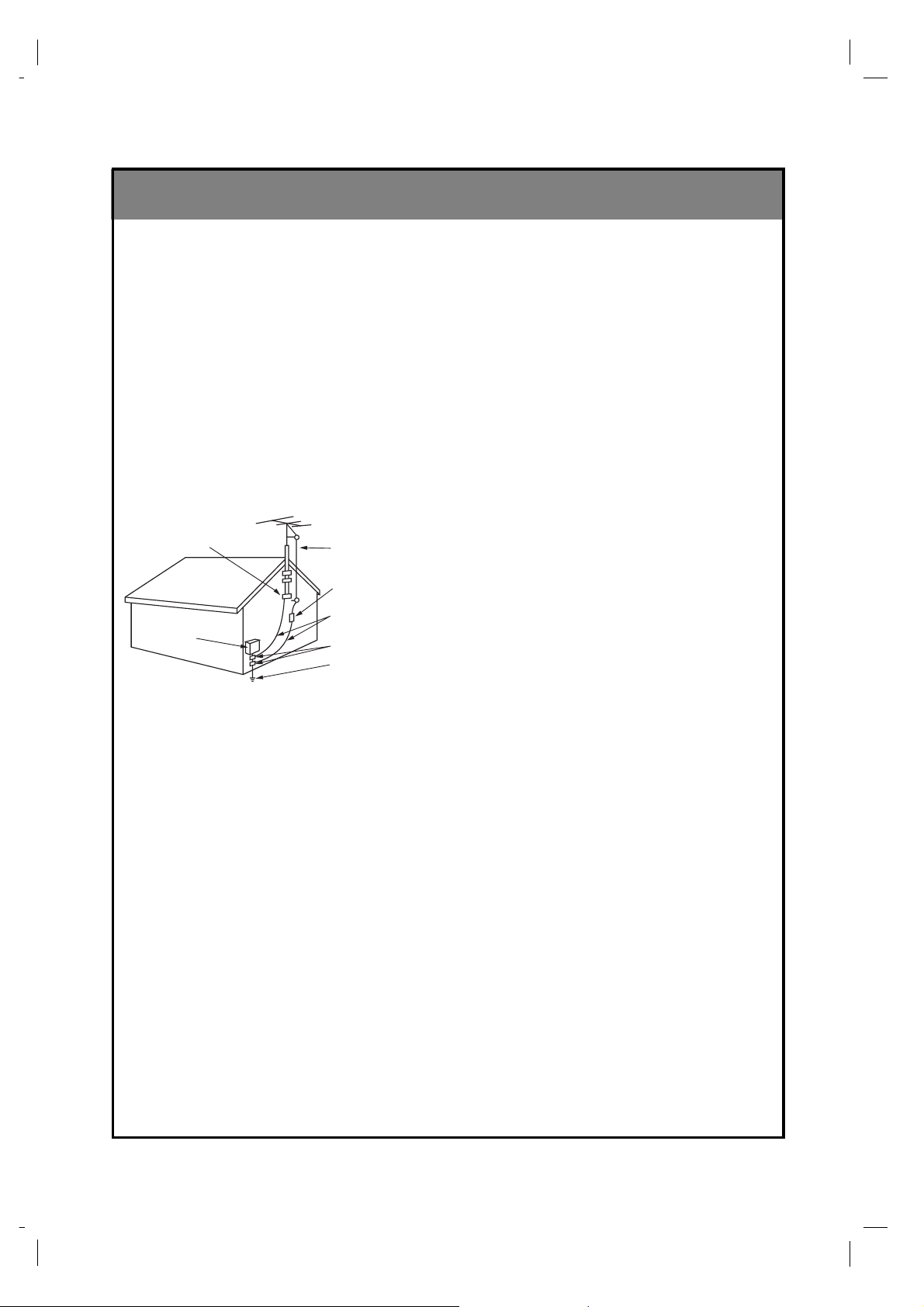
Antenna Lead in Wire
Antenna Discharge Unit
(NEC Section 810-20)
Grounding Conductor
(NEC Section 810-21)
Ground Clamps
Power Service Grounding
Electrode System (NEC
Art 250, Part H)
Ground Clamp
Electric Service
Equipment
Example of Grounding According to National
Electrical Code Instructions
NEC - National Electrical Code
206-3779

206-3779
55
1
Safety precautions 2
Controls 6
TV Overview 10
TV Installation and Setup 11
2
3
4
5
7
Antenna Connections 13
VCR Connections 14
External Equipment Connections 15
DVD Player Connections 16
DTV (Set-top Box) Connections 17
PC/Computer Connections 18
(use TV as a Monitor)
PC Mode Functions Check 20
PC Mode Adjustments 21
Remote Control: Installing Batteries/Operation 26
To turn the TV on 27
TV Mode Available Menus 28
Menu Language Selection 29
Auto Programming: Finding/Erasing channels 30
Video/Picture Setup 38
Audio/Sound Setup 42
6
Closed Captions 48
Parental Control 51
Auto Off 54
Key Lock 55
Setting the Clock 32
Setting Off Timer 33
Setting On Timer 35
Sleep Timer Setup 37
Specifications 56
Maintenance 57
Troubleshooting Check List 58
Your Zenith Limited Warranty Back cover
Before operating the
TV, please read this
manual carefully.
CONTENTS
INDEX
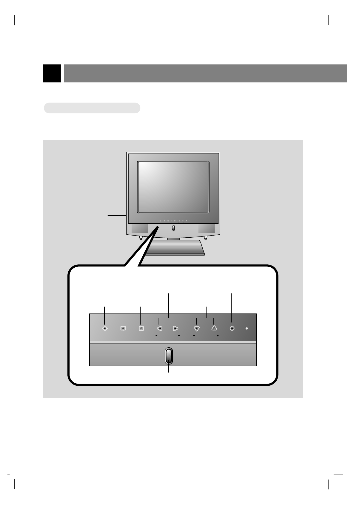
Controls
6
206-3779
Front of the
Front of the TVTV
Front control panel
Front control panel
TV/Video button
Enter button
Channel buttons
Power buttonMenu button
Remote control sensor
Volume buttons
On indicator
on/off button
enter vol vol
menu
tv/video
power
ch ch
power
tv/video enter
menu
vol vol ch ch
206-3779
7
INTRODUCTION
DC 12V
ANT IN
+75 Ω
PC INPUT
COMPONENT(480i/480p/720p/1080i)
S-VIDEO H/P
PC
SOUND
IN
DVD/DTV IN
AUDIO
RLVIDEO
P
R
P
B
Y L R
AUDIO(MONO)
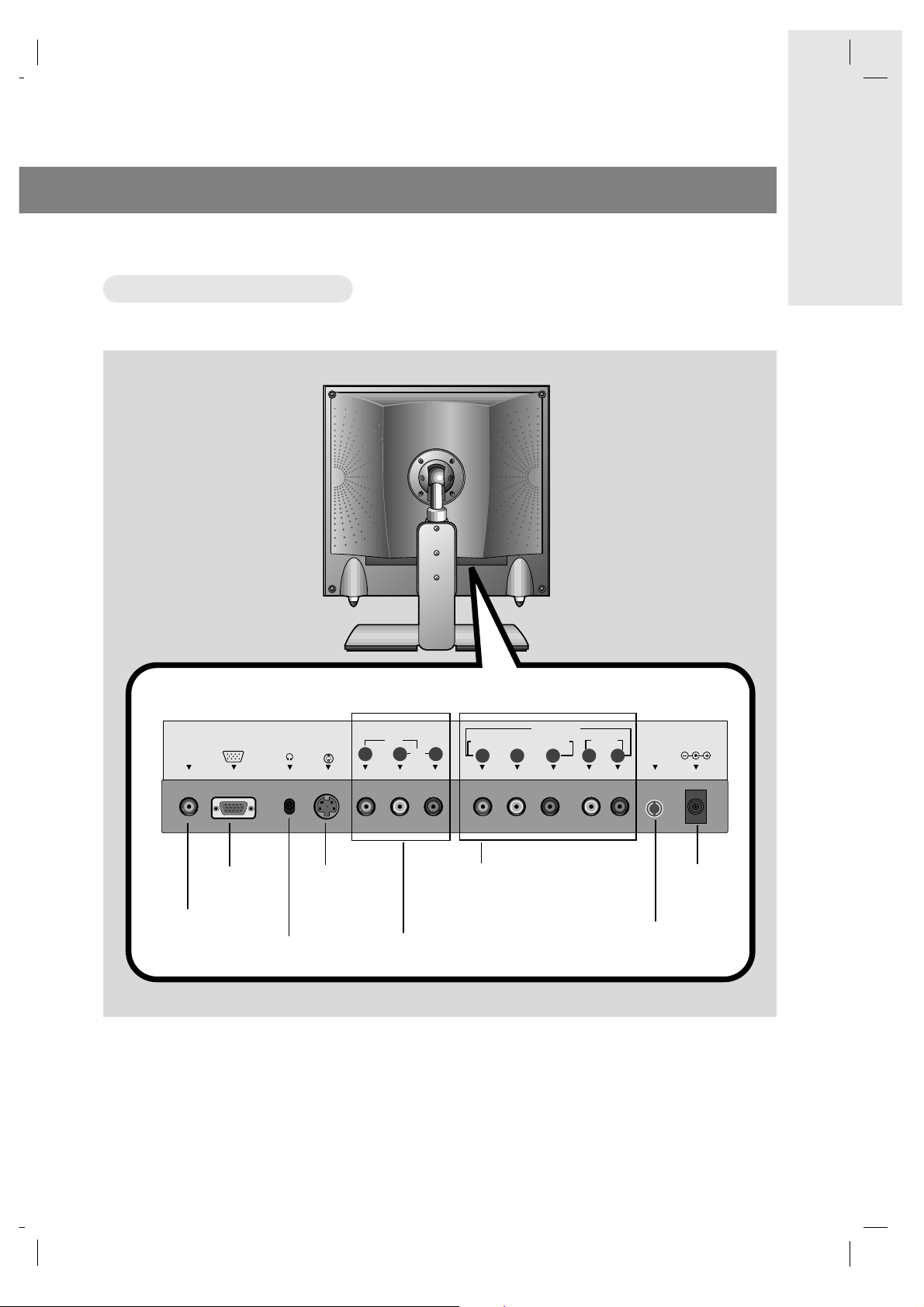
Back of the
Back of the TVTV
Audio/Video input
Headphone jack
PC input
PC sound input
S-Video input
Antenna input
DC 12V input
DVD/DTV IN
(Component (480i/480p/720p/1080i),
AUDIO) input
Connection Panel
Connection Panel
206-3779
power
flashbk
menu
mute
sleep
ch
enter
vol vol
ch
cc
tv/video
0
2 3
5 64
8 97
1
mts
pip
ch
pip input
position
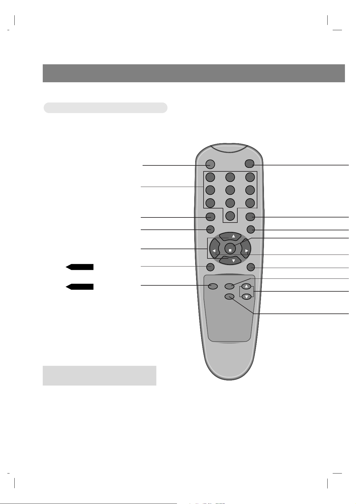
Controls
8
POWER BUTTON
NUMBER BUTTONS
FLASHBK BUTTON
MENU BUTTON
CHANNEL (
D,E
) BUTTONS
MTS BUTTON
PIP BUTTON
Remote Control Overview
Remote Control Overview
PAGE 46
PAGE 23
● Press the flashbk button to view the last
program you were watching.
206-3779
9
INTRODUCTION
TV/VIDEO BUTTON
CAPTION BUTTON
MUTE BUTTON
ENTER BUTTON
VOLUME (
F,G
) BUTTONS
SLEEP BUTTON
PAGE 50
PAGE 47
PAGE 37
PAGE 24
PAGE 24
PAGE 23
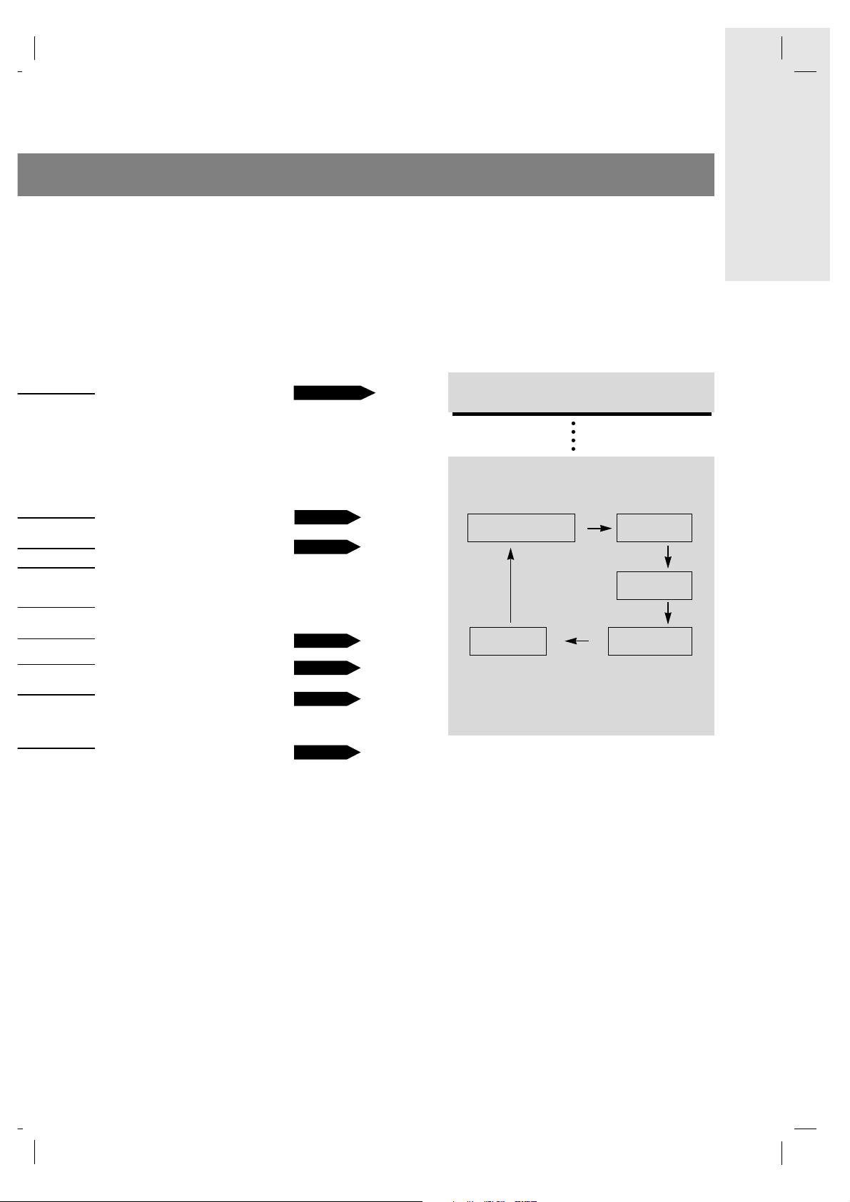
TV/VIDEO button
TV/VIDEO button
on Remote Control
on Remote Control
* Each press of this button changes the
viewing source as indicted below.
* VIDEO, S-VIDEO, COMPONENT, PC
: Select each mode for watching the corre-
sponding external equipment.
TV programs
/Cable TV
Video
S-Video
RGB-PC
Component
PAGE 14~18
POSITION BUTTON
PIP CHANNEL BUTTONS
PIP INPUT BUTTON
TV overview
10
206-3779
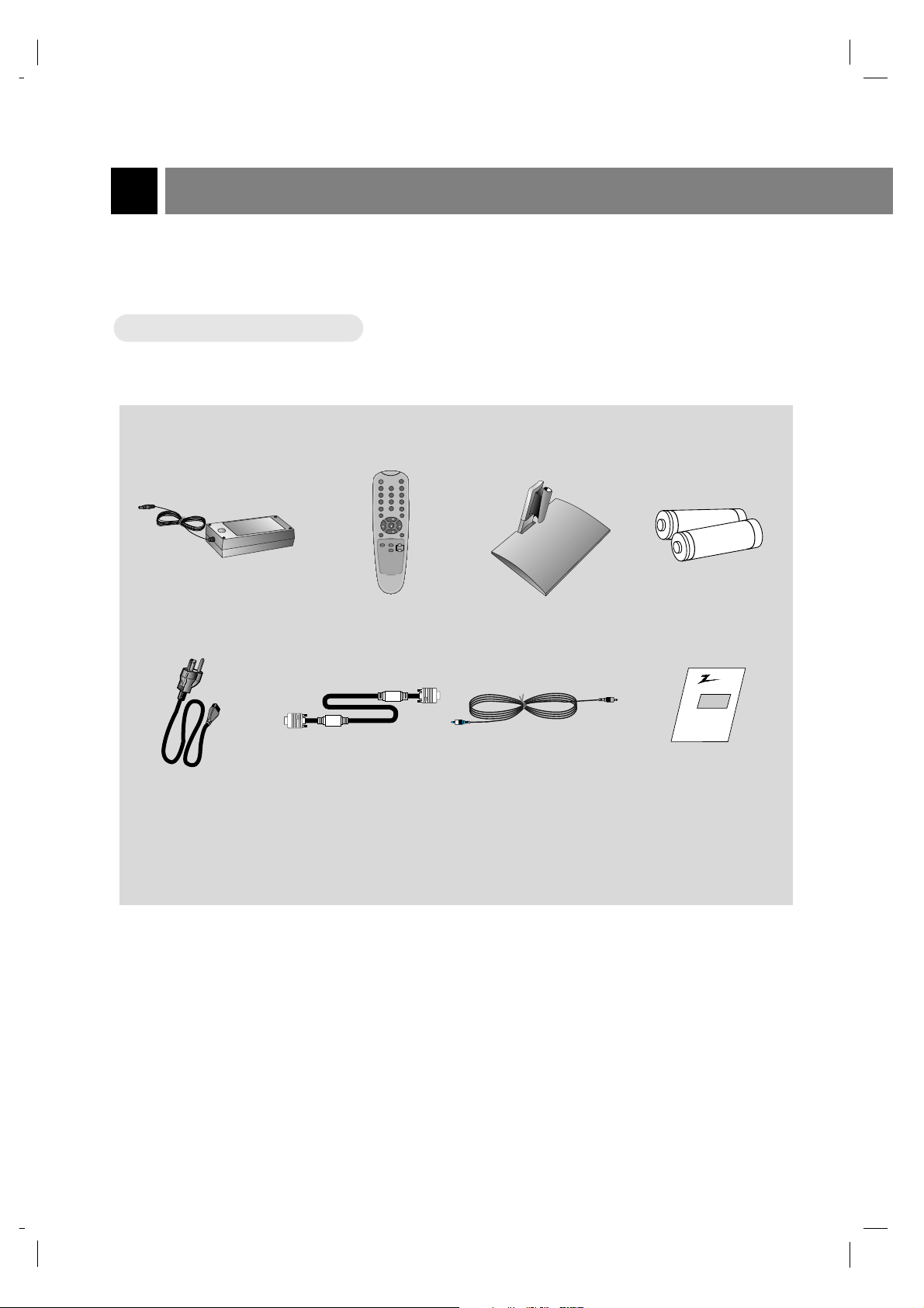
AC Adapter
Remote Control
PC signal cable PC sound cable
Accessories
Accessories
1.5V
1.5V
Power cord
Operating guide
AAA
Batteries
power
flashbk
menu
mute
sleep
ch
enter
vol vol
ch
cc
tv/video
0
2 3
5 64
8 97
1
mts
pip
ch
pip input
position
AS mark
Zenith
Table style stand
TV Installation and Setup
11
INTRODUCTION
206-3779
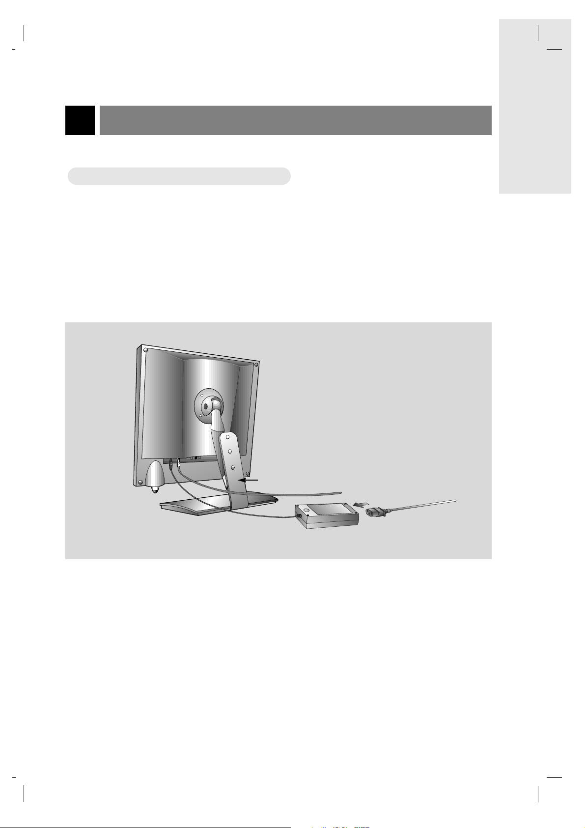
* Please make sure to connect the TV to the adapter before connecting the power plug to the wall power outlet.
a. Install the LCD TV correctly using the installation accessories. Refer to page 12.
b. Connect the antenna cable to the antenna input port on the TV.
c. Connect the AC power adapter to the power input port on the TV.
d. Plug the power cord into the wall power outlet after connecting the power cord to the adapter.
WWatching
atching
TV Programs
TV Programs
Notes : ● If the TV feels cold to the touch, there may be a small “flicker” when turned on.
This is normal, there is nothing wrong with TV.
● Some minor dot defects may appear on the screen, like red, green or blue spots.
However, this will have no adverse effect on the monitor's performance.
● Avoid touching the LCD screen or holding your finger(s) against it for long periods of time.
Doing so may produce some temporary distortion effects on the screen.
a
b
c
d
206-3779
TV Installation and Setup continued
12
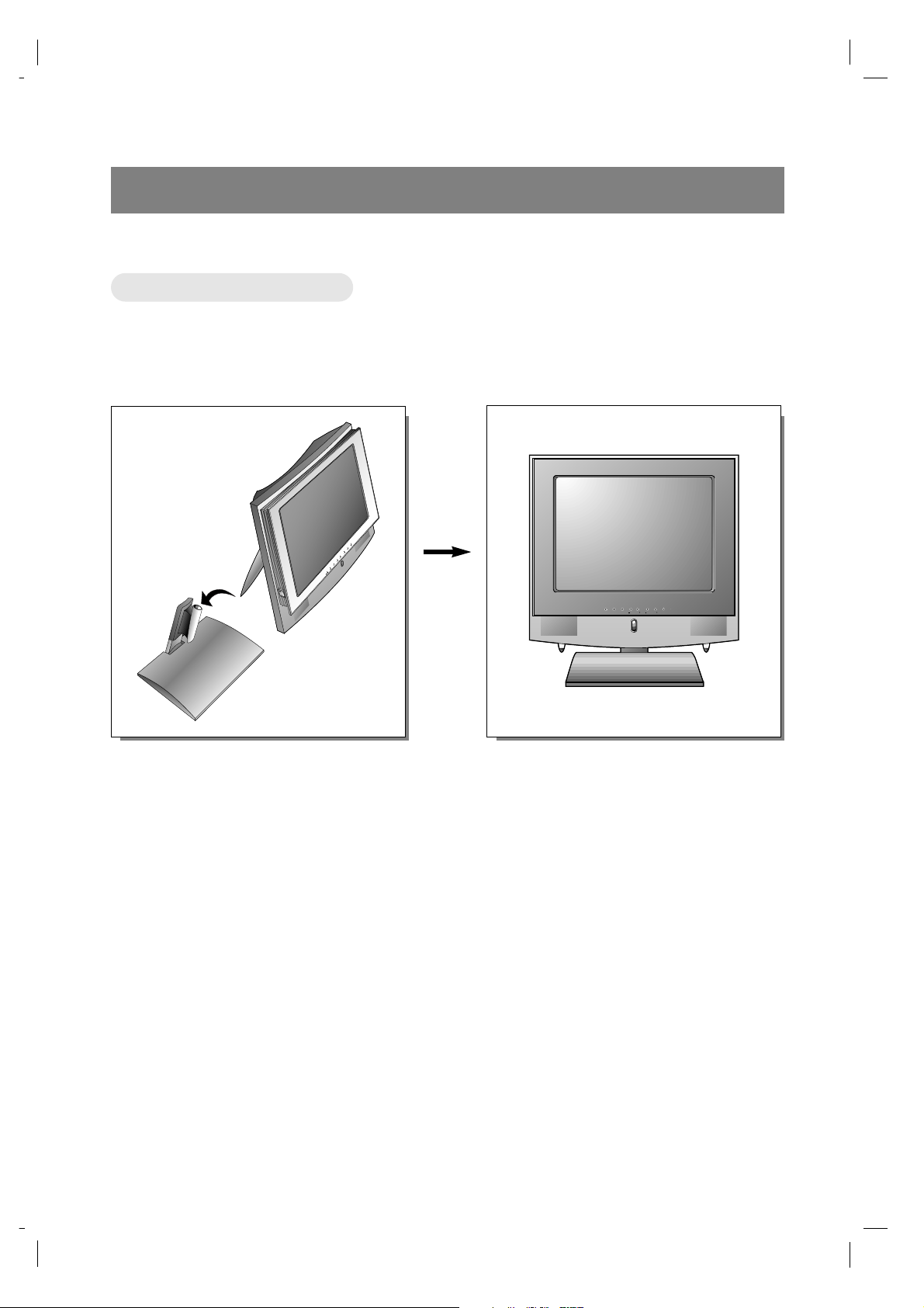
Stand Installation
Stand Installation
a. Place the table stand in the position where you want to install the TV.
b. Put the set in the table stand.
* When you install the TV into the table style stand, please insert the stick on the back of the TV into the
hole provided on the table style stand securely so as to not allow any movement.
* For safety, only use table style stand.
enter vol vol
menu
tv/video
power
ch ch
206-3779
Antenna Connections
13
CONNECTIONS
DC 12V
ANT IN
+75 Ω
AUDIO
L R
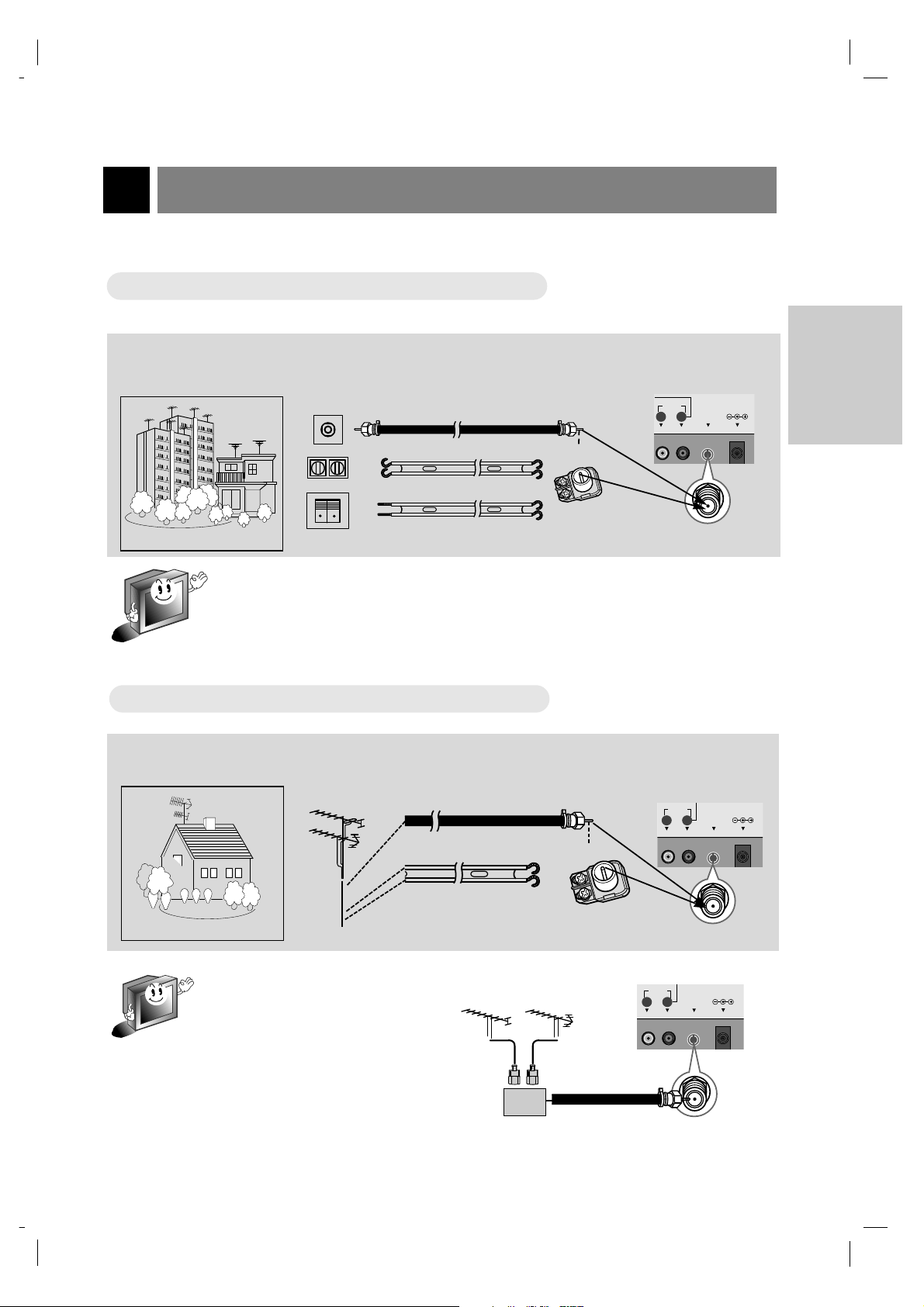
* For better picture quality, adjust antenna direction.
● Typical wall antenna jack used in apartment buildings, connect the antenna cable as shown below.
(Use the correct type of antenna cable for the type of wall antenna jack.)
Wall Connection Jack
Apartment Buildings
Antenna Jack
Bronze Wire
Turn clockwise to
tighten.
Antenna
Converter
300Ω Flat Wire
75Ω Round Cable
● This type of antenna is commonly used in single family homes.
UHF
Antenna
VHF Antenna
Antenna Jack
Bronze Wire
Turn clockwise to
tighten.
Antenna
Converter
300Ω Flat Wire
75Ω Round Cable
* If you have a 75Ω round cable, insert the bronze wire and then tighten the connection
nut. And if you have a 300Ω flat wire, connect the twisted wire to the antenna converter
and then connect the converter to the antenna jack.
* When using 75Ω round cable, do not bend the bronze wire. It may cause poor picture
quality.
* In poor signal areas, you can get bet-
ter picture quality if you install the
antenna as shown at right.
* If antenna is split for two TVs, use
“signal divider” for connection.
Signal
Amplifier
UHF
VHF
Single Family Home
Connecting to wall antenna socket
Connecting to wall antenna socket
Connecting to outdoor antenna
Connecting to outdoor antenna
DC 12V
ANT IN
+75 Ω
AUDIO
L R
AUDIO
ANT IN
+75 Ω
L R
DC 12V
VCR Connections
14
206-3779
* In Video mode, TV automatically reverts to TV mode if the channel (D,E) buttons or number buttons (0~9) are
pressed.
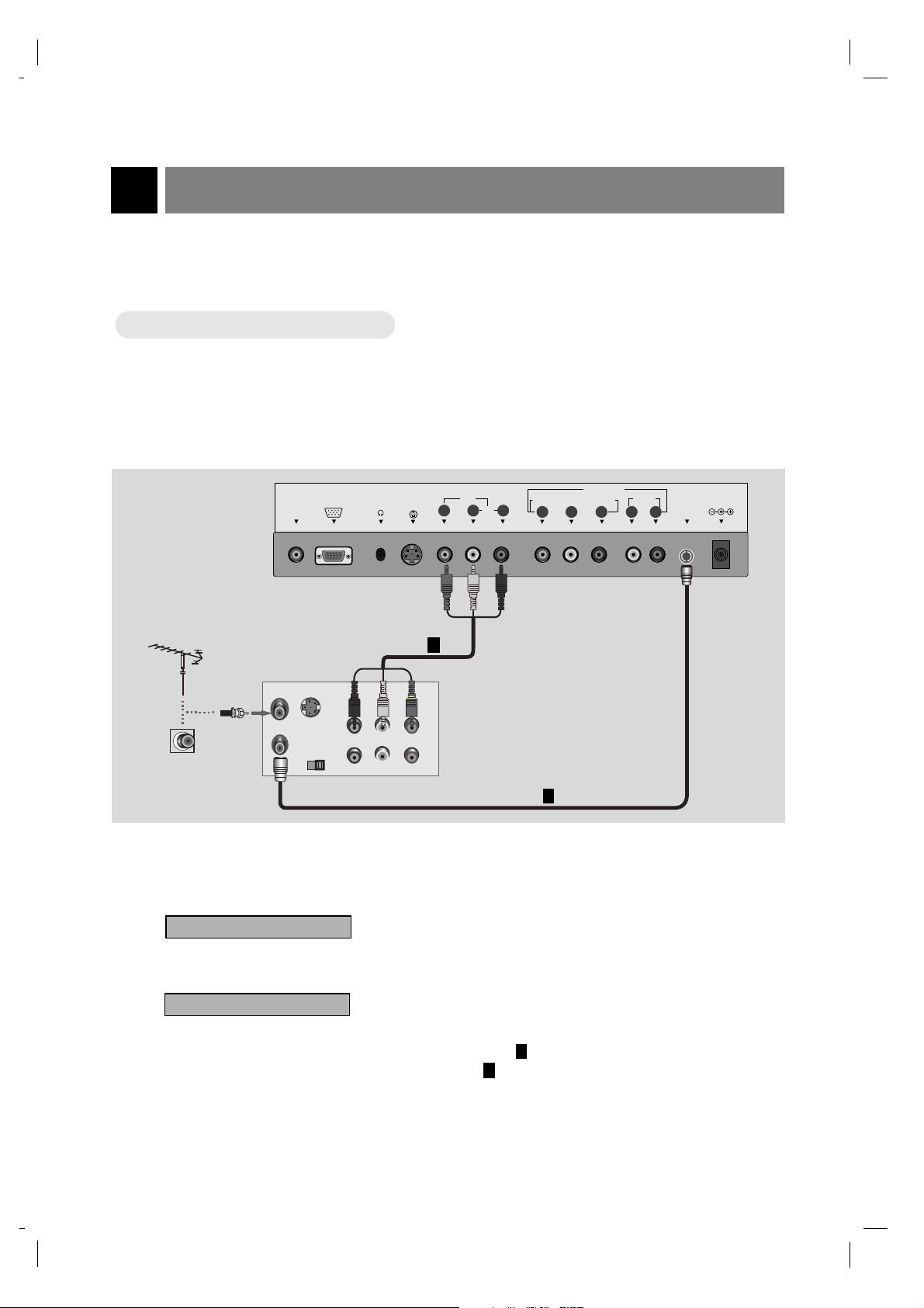
* Connect to other AV equipment using input jacks on the TV.
1
How to connect
● Connect the audio/video output jacks on VCR to the corresponding input jacks on the TV.
2
How to use
Watching TV programs
Turn the TV on and tune to a channel.
Watching VCR
a. Press tv/video button of the remote control to select Video mode.
* Select the channel 3 or 4 for only ANT IN connection .
* Select VIDEO to use Audio/Video In connection .
b. Insert a video tape into the VCR and press the PLAY button.
2
1
Connecting a VCR
Connecting a VCR
1
Typical
Antennas
VCR Connection Panel
Direct
connection
2
PC
SOUND
ANT IN
ANT OUT
S-VIDEO
CH3 CH4
PC INPUT
OUT
IN
(R) (L)
AUDIO VIDEO
S-VIDEO H/P
IN
AUDIO(MONO)
COMPONENT(480i/480p/720p/1080i)
RLVIDEO
DVD/DTV IN
PRPBY L R
AUDIO
ANT IN
+75 Ω
DC 12V
206-3779
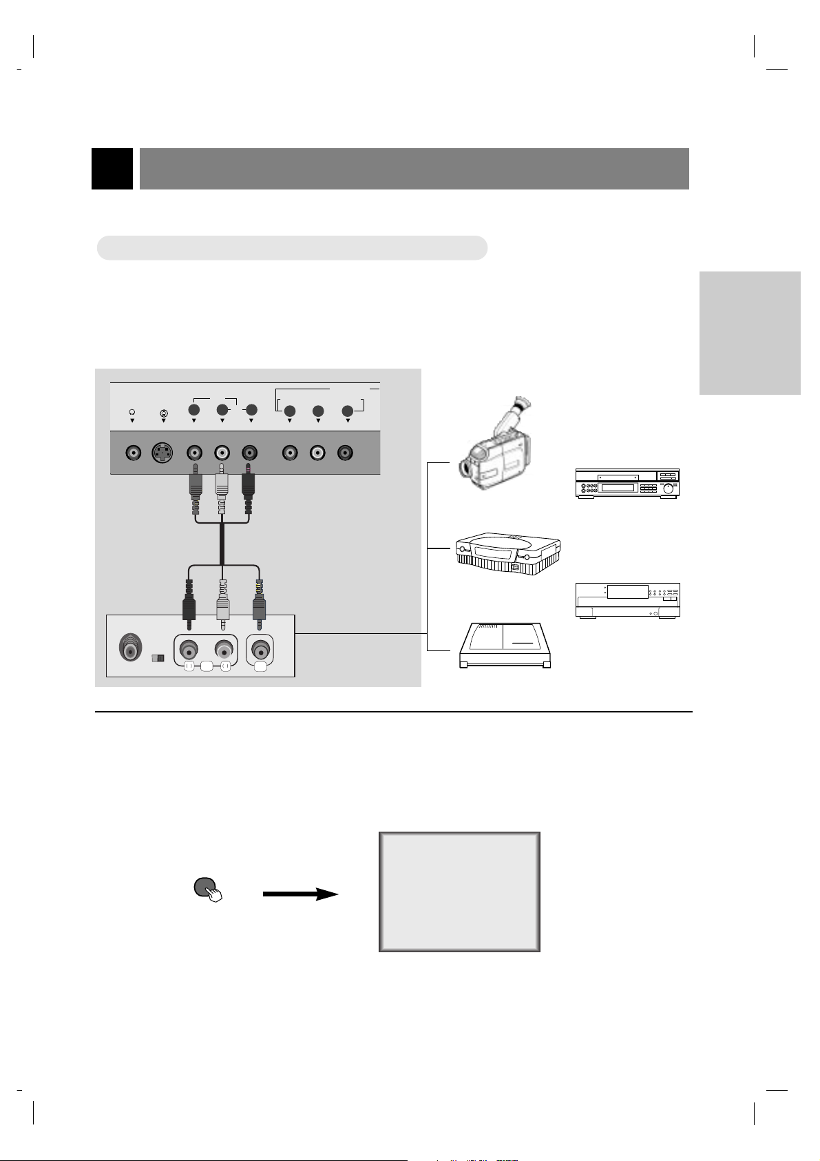
External Equipment Connections
15
CONNECTIONS
1
How to connect
● Connect the audio/video output jacks on the external A/V equipment to the corresponding input
jacks on the TV.
2
How to use
Camcorder
CDGP
VCDP
Video Game set
CDI
Video
● Turn on the external A/V equipment.
● Turn the TV on and press
tv/video button to select Video mode.
On Remote Control
WWatching external
atching external
A/V source
A/V source
TV Connection Panel
External Equipment
Connection Panel
tv/video
S-VIDEO H/P
IN
(MONO)
AUDIO VIDEO
R
L
AUDIO
COMPONENT(480i/480p/720p/1080i)
RLVIDEO
Y
DVD/DTV IN
P
B
P
R
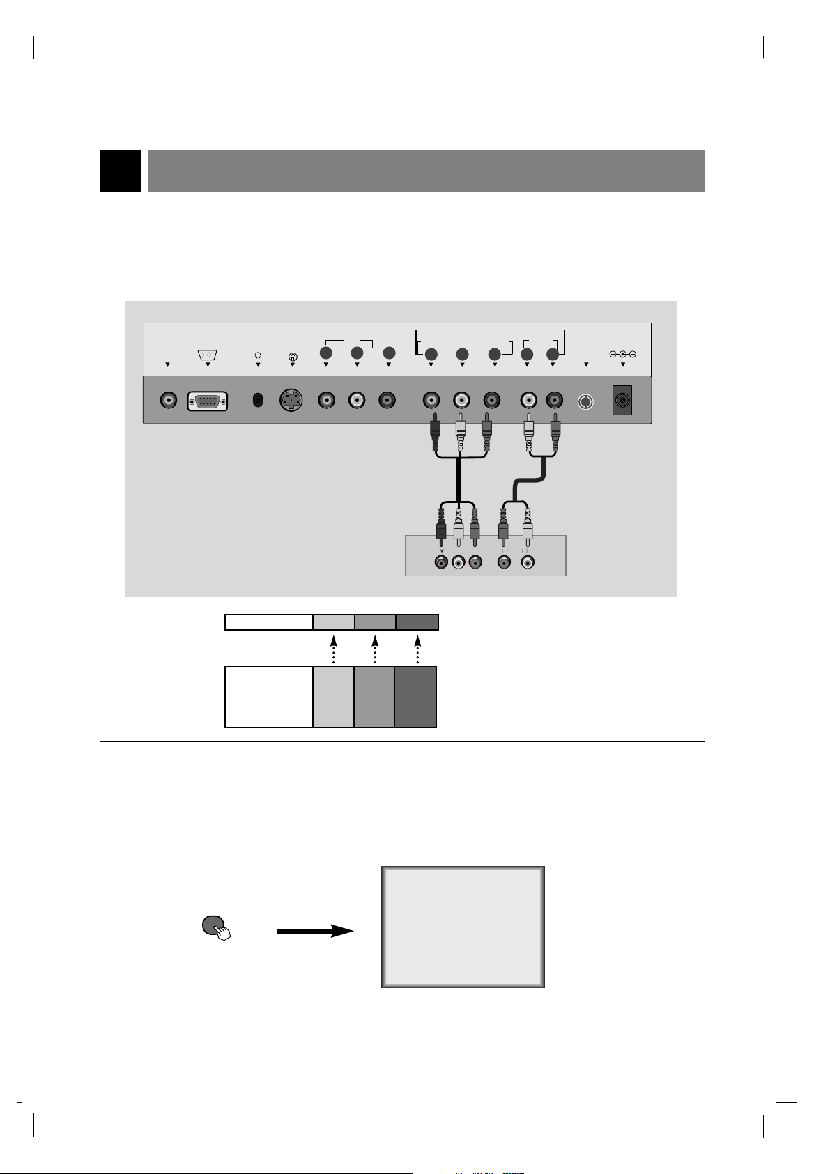
DVD Player Connections
16
206-3779
1
How to connect
2
How to use
Component
● Turn on the DVD player.
● Turn the TV on and use
tv/video button to select Component source.
● See DVD/DTV user's manual for operating instructions.
On Remote Control
● Connect DVD/DTV output jacks to TV's COMPONENT (480i/480p/720p/1080i), Y, PB, PR jacks.
Connect DVD/DTV audio output jacks to right and left input jacks on TV.
TV Connection Panel
DVD Connection Panel
TV INPUT Y PB PR
DVD OUTPUT Y
Y
Y
Y
Cb
B-Y
Pb
PB
Cr
R-Y
Pr
PR
Note:
tv/video
PC
SOUND
PC INPUT
S-VIDEO H/P
IN
P
B
PBP
DVD/DTV IN
R
AUDIO(MONO)
Y L R
COMPONENT(480i/480p/720p/1080i)
RLVIDEO
AUDIO
P
R
AUDIO LR
ANT IN
+75 Ω
DC 12V
206-3779
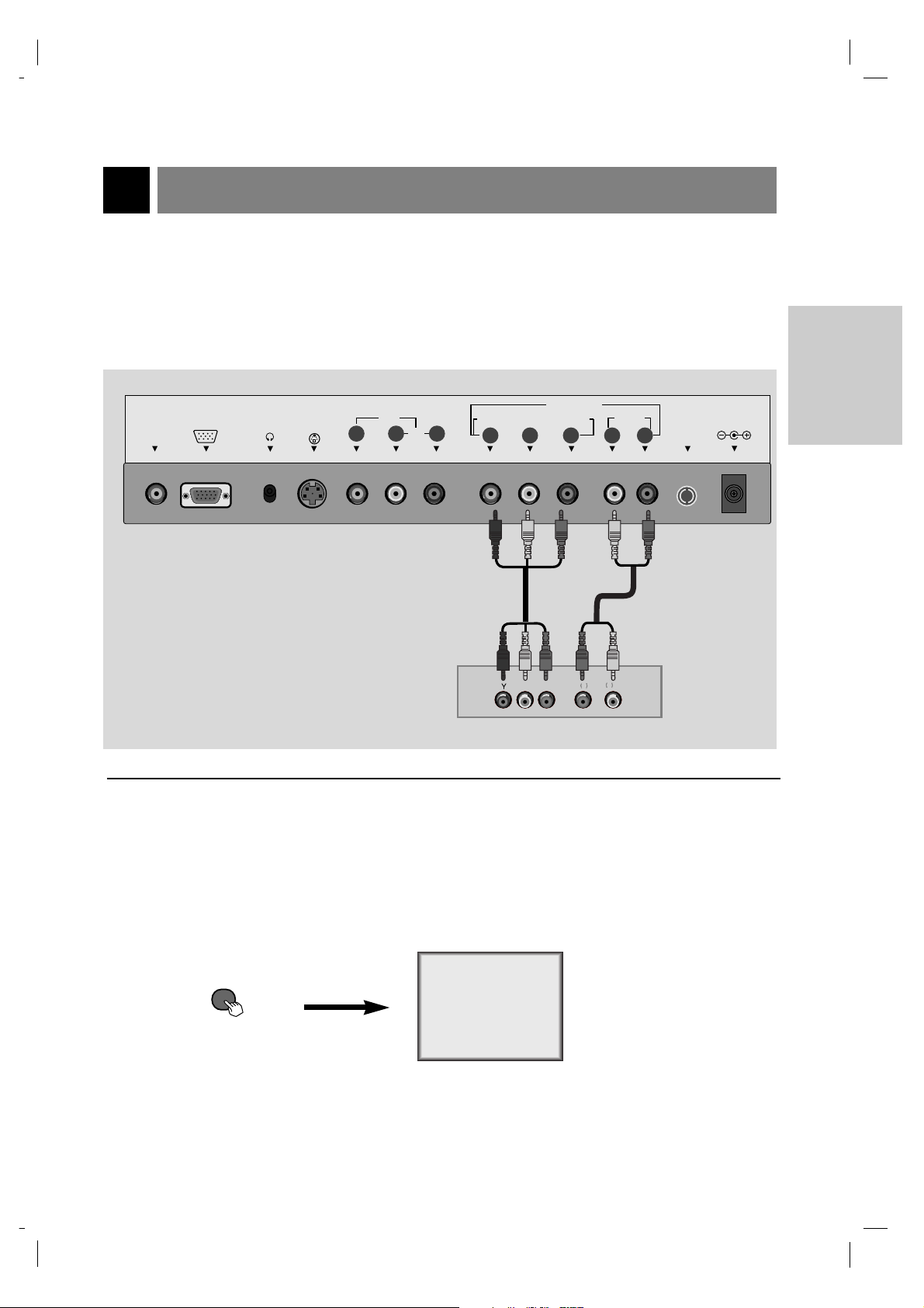
DTV (Set-top Box) Connections
17
CONNECTIONS
1
How to connect
2
How to use
Component
● Turn on the DTV receiver (Set-top Box).
● Turn the TV on and use
tv/video button to select Component source.
On Remote Control
● Connect DVD/DTV output to COMPONENT(480i/480p/720p/1080i), Y, PB, PR jack inputs on the TV.
Connect DTV L/R audio outputs to the TV's AUDIO L/R input jacks.
Note: ADTV set-top box is required to receive DTV programming.
TV Connections Panel
DTV Receiver (Set-top Box) Connections Panel
tv/video
PC
SOUND
PC INPUT
S-VIDEO H/P
IN
AUDIO(MONO)
COMPONENT(480i/480p/720p/1080i)
RLVIDEO
DVD/DTV IN
PRPBY L R
AUDIO
ANT IN
+75 Ω
DC 12V
PBP
AUDIO LR
R
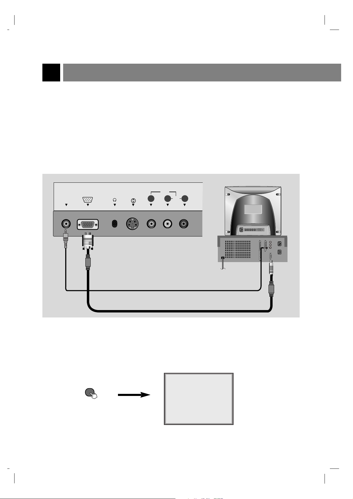
PC/Computer Connections (using TV as a Monitor)
18
206-3779
2
How to use
RGB-PC
● Turn on the PC/Computer.
● Turn the TV on and use
tv/video button to select RGB-PC source.
On Remote Control
1
How to connect
● Set the monitor output resolution on the PC before connecting to the TV. See the next page.
● Connect the TV to the PC with the PC cable.
● Connect the PC audio output to the TV's PC SOUND input.
TV Connections Panel
PC Connections Panel
* After setup, be sure to set TV to PC source.
tv/video
PC INPUT
PC
SOUND
S-VIDEO H/P
IN
RLVIDEO AUDIO(MONO)
 Loading...