


machine number ZLD15A1
®
enjoy the view
Copyright 2000, Zenith Electronics Corporation.
operating guide / warranty

RECORD YOUR MODEL NUMBER
WARNING
RISK OF ELECTRIC SHOCK
DO NOT OPEN
(Now, while you can see it)
The model and serial number of your new TV are located
on the back of the TV cabinet. For your future convenience, we suggest that you record these numbers here:
MODEL
NO.____________________________________
SERIAL
NO.____________________________________
WARNING :
TO REDUCE THE RISK OF ELECTRIC SHOCK DO NOT REMOVE COVER (OR BACK).
NO USER SERVICEABLE PARTS INSIDE.
REFER SERVICING TO QUALIFIED SERVICE PERSONNEL.
The lightning flash with arrowhead symbol, within an equilateral triangle, is intended to alert
the user to the presence of uninsulated “dangerous voltage” within the product’s enclosure
that may be of sufficient magnitude to constitute a risk of electric shock to persons.
The exclamation point within an equilateral triangle is intended to alert the user to the presence of important operating and maintenance (servicing) instructions in the literature accompanying the appliance.
WARNING :
TO PREVENT FIRE OR SHOCK HAZARDS, DO NOT EXPOSE THIS PRODUCT TO
RAIN OR MOISTURE.
NOTE TO CABLE/TV INSTALLER:
This reminder is provided to call the cable TV system installer’s attention to Article 820-40 of
the National Electric Code (U.S.A.). The code provides guidelines for proper grounding and,
in particular, specifies that the cable ground shall be connected to the grounding system of
the building, as close to the point of the cable entry as practical.
REGULATORY INFORMATION:
This equipment has been tested and found to comply with the limits for a Class B digital
device, pursuant to Part 15 of the FCC Rules. These limits are designed to provide reasonable protection against harmful interference when the equipment is operated in a residential
installation. This equipment generates, uses and can radiate radio frequency energy and, if
not installed and used in accordance with the instruction manual, may cause harmful interference to radio communications. However, there is no guarantee that interference will not
occur in a particular installation. If this equipment does cause harmful interference to radio
or television reception, which can be determined by turning the equipment off and on, the
user is encouraged to try to correct the interference by one or more of the following measures:
CAUTION:
Do not attempt to modify this product in any way without written authorization from Zenith
Electronics Corporation. Unauthorized modification could void the user’s authority to operate
this product.
• Reorient or relocate the receiving antenna.
• Increase the separation between the equipment and receiver.
• Connect the equipment into an outlet on a circuit different from that to
which the receiver is connected.
• Consult the dealer or an experienced radio/TV technician for help.
“Entertainment Machine” is a trademark of Zenith Electronics Corporation
2
206-3652
IMPORTANT SAFETY INSTRUCTIONS
PORTABLE CART WARNING
Important safeguards for you and your new product
Your product has been manufactured and tested with your safety in mind. However, improper use
can result in potential electrical shock or fire hazards. To avoid defeating the safeguards that have
been built into your new product, please read and observe the following safety points when
installing and using your new product, and save them for future reference.
Observing the simple precautions discussed in this booklet can help you get many years of enjoyment and safe operation that are built into your new product.
This product complies with all applicable U.S. Federal safety requirements, and those of the
Canadian Standards Association.
INTRODUCTION
1. Read Instructions
All the safety and operating instructions should
be read before the product is operated.
2. Follow Instructions
All operating and use instructions should be followed.
3. Retain Instructions
The safety and operating instructions should be
retained for future reference.
4. Heed Warnings
All warnings on the product and in the operating
instructions should be adhered to.
5. Cleaning
Unplug this product from the wall outlet before
cleaning. Do not use liquid cleaners or aerosol
cleaners. Use a damp cloth for cleaning.
6. Water and Moisture
Do not use this product near water - for example, near a bath tub, wash bowl, kitchen sink, or
laundry tub, in a wet basement, or near a swimming pool.
7. Accessories
Do not place this product on an unstable cart,
stand, tripod, bracket, or table. The product may
fall, causing serious injury to a child or adult,
and serious damage to the product. Use only
with a cart, stand, tripod, bracket, or table recommended by the manufacturer, or sold with the
product. Any mounting of the product should follow the manufacturer’s instructions, and should
use a mounting accessory recommended by the
manufacturer.
8. Transporting Product
A product and cart combination should be
moved with care. Quick stops, excessive force,
and uneven surfaces may cause the product
and cart combination to overturn.
9. Attachments
Do not use attachments not recommended by
the product manufacturer as they may cause
hazards.
10. Ventilation
Slots and openings in the cabinet are provided
for ventilation and to ensure reliable operation of
the product and to protect it from overheating,
and these openings must not be blocked or covered. The openings should never be blocked by
placing the product on a bed, sofa, rug, or other
similar surface. This product should not be
placed in a built-in installation such as a bookcase or rack unless proper ventilation is provided or the manufacturer’s instructions have been
adhered to.
11. Power Sources
This product should be operated only from the
type of power source indicated on the marking
label. If you are not sure of the type of power
supply to your home, consult your product dealer or local power company. For products intended to operate from battery power, or other
sources, refer to the operating instructions.
12. Line-Cord Polarization
This product is equipped with a three-wire
grounding type alternating-current line plug (a
plug having one blade wider than the other).
This plug will fit into the power outlet only one
way. This is a safety feature. If you are unable
to insert the plug fully into the outlet, contact
your electrician to replace your obsolete outlet.
Do not defeat the safety purpose of the polarized plug.
13. Power-Cord Protection
Power-supply cords should be routed so that
they are not likely to be walked on or pinched
by items placed upon or against them, paying
particular attention to cords at plugs, convenience receptacles, and the point where they
exit from the product.
206-3652
(Continued on next page)
3
IMPORTANT SAFETY INSTRUCTIONS
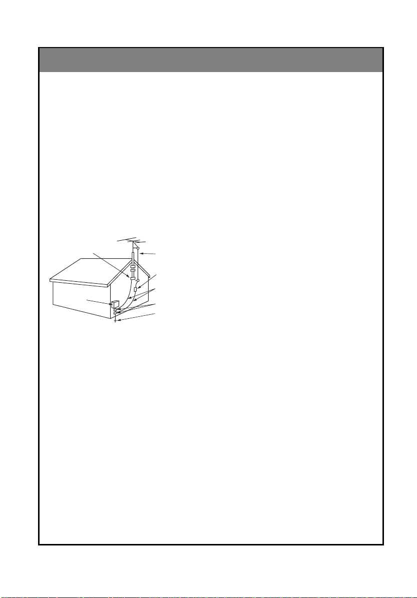
Antenna Lead in Wire
Antenna Discharge Unit
(NEC Section 810-20)
Grounding Conductor
(NEC Section 810-21)
Ground Clamps
Power Service Grounding
Electrode System (NEC
Art 250, Part H)
Ground Clamp
Electric Service
Equipment
(Continued from previous page)
14. Outdoor Antenna Grounding
If an outside antenna or cable system is connected to the product, be sure the antenna or
cable system is grounded so as to provide some
protection against voltage surges and built-up
static charges. Article 810 of the National
Electrical Code (U.S.A.), ANSI/ NFPA70 provides information with regard to proper grounding of the mast and supporting structure,
grounding of the lead-in wire to an antenna discharge unit, size of grounding conductors, location of antenna-discharge unit, connection to
grounding electrodes, and requirements for the
grounding electrode.
Example of Grounding According to National
Electrical Code Instructions
NEC - National Electrical Code
15. Lightning
For added protection for this product (receiver)
during a lightning storm, or when it is left unattended and unused for long periods of time,
unplug it from the wall outlet and disconnect the
antenna or cable system. This will prevent damage to the product due to lightning and powerline surges.
16. Power Lines
An outside antenna system should not be located in the vicinity of overhead power lines or
other electric light or power circuits, or where it
can fall into such power lines or circuits. When
installing an outside antenna system, extreme
care should be taken to keep from touching
such power lines or circuits as contact with them
might be fatal.
17. Overloading
Do not overload wall outlets and extension
cords as this can result in a risk of fire or electric
shock.
18. Object and Liquid Entry
Never push objects of any kind into this product
through openings as they may touch dangerous
voltage points or short-out parts that could result
in a fire or electric shock. Never spill liquid of
any kind on the product.
19. Servicing
Do not attempt to service this product yourself
as opening or removing covers may expose you
to dangerous voltage or other hazards. Refer all
servicing to qualified service personnel.
20. Damage Requiring Service
Unplug this product from the wall outlet and
refer servicing to qualified service personnel
under the following conditions:
a. If the power-supply cord or plug is damaged.
b. If liquid has been spilled, or objects have fall-
en into the product.
c. If the product has been exposed to rain or
water.
d. If the product does not operate normally by
following the operating instructions. Adjust only
those controls that are covered by the operating
instructions as an improper adjustment of other
controls may result in damage and will often
require extensive work by a qualified technician
to restore the product to its normal operation.
e. If the product has been dropped or the cabinet has been damaged.
f. If the product exhibits a distinct change in
performance.
21. Replacement Parts
When replacement parts are required, be sure
the service technician has used replacement
parts specified by the manufacturer or have the
same characteristics as the original part.
Unauthorized substitutions may result in fire,
electric shock, or other hazards.
22. Safety Check
Upon completion of any service or repairs to this
product, ask the service technician to perform
safety checks to determine that the product is in
proper operating condition.
23. Wall or Ceiling Mounting
The product should be mounted to a wall or ceiling only as recommended by the manufacturer.
24. Heat
The product should be situated away from heat
sources such as radiators, heat registers,
stoves, or other products (including amplifiers)
that produce heat.
4
206-3652

CONTENTS
INDEX
Safety warnings 2
1
Important safety instructions 3
Controls 6
Basic composition of LCD TV 10
Connecting antenna 14
2
Connecting external equipment 15
Connecting DVD player 17
Connecting DTV 18
Connecting PC as monitor 19
3
Function checking in PC mode 21
Using remote control 22
4
Turning on the set 23
Function checking in TV mode 24
Setting language 25
Closed caption function 26
Parental control function 30
Programming / Erasing channels 32
Setting current time 34
5
Setting Off-Timer function 36
Setting On-Timer function 38
Setting sleep time function 40
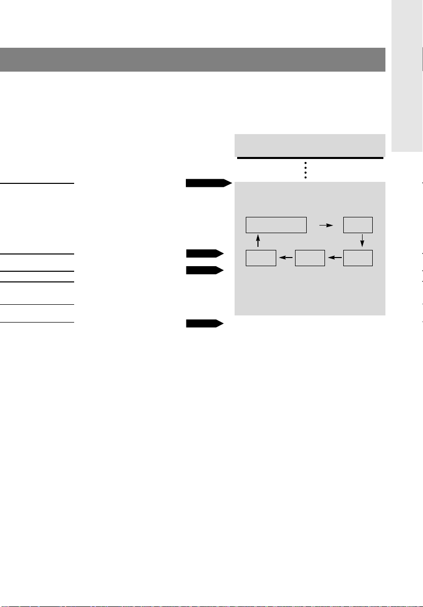
INTRODUCTION
INTRODUCTION
CONNECTION
CONNECTIONPC
PC
CONNECTION
CONNECTION
BASIC
BASIC
FUNCTIONS
FUNCTIONS
CLOCK
CLOCK
SETTING
SETTING
Before operating the
set, please read this
manual carefully.
206-3652
Adjusting audio condition 41
6
Adjusting video condition 44
Product specifications 46
7
Your Zenith Limited Warranty Backcover
AUDIO /
AUDIO /
VIDEO
VIDEO
INFORMATION
INFORMATION
5

Controls
Front of the set
Front of the set
enter vol vol
menu
tv/video
* Remove vinyl coating for protection from staining before using.
Back of the set
Back of the set
power
ch ch
On indicator
Power button
Remote control sensor
206-3652
6

DC 12V
ANT IN
+75 Ω
PC/D-TV INPUT
S-VIDEO INPUT
H/P
RLVIDEOINAUDIO
(MONO)
COMPONENT INPUT(480i)
BPPR
Front control panel
Front control panel
TV/Video button
Enter button Channel buttons
Volume buttons
INTRODUCTION
Power buttonMenu button
On indicator
tv/video enter
Connecting ports
Connecting ports
menu
Power input
Antenna input
vol vol ch ch
Remote control sensor
Component input Headphone
jack
PC / D-TV input S-Video input
power
Audio/Video
input
206-3652
7
Controls
0
2 31
5 64
8 97
power
flashbk
menu
mute
sleep
ch
enter
vol vol
ch
cc
tv/video
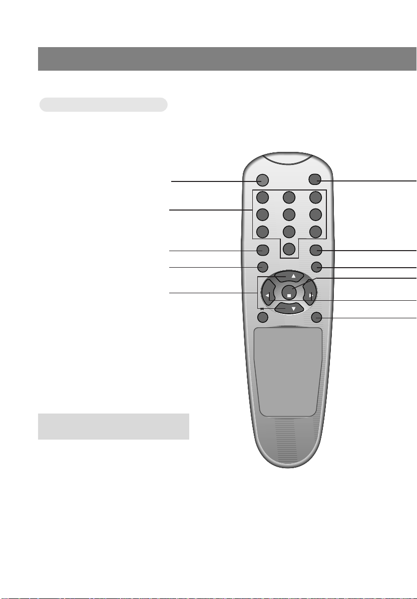
Remote Control
Remote Control
POWER BUTTON
NUMBER BUTTONS
FLASHBK BUTTON
MENU BUTTON
CHANNEL (
D,E
) BUTTONS
● Press the flashbk button to view the last
programme you were watching.
8
206-3652
TV/VIDEO button
TV/VIDEO button
on Remote Control
on Remote Control
INTRODUCTION
TV/VIDEO BUTTON
CC BUTTON
MUTE BUTTON
ENTER BUTTON
VOLUME (
F,G
) BUTTONS
SLEEP BUTTON
PAGE 16~20
PAGE 28
PAGE 43
PAGE 40
* Each press of this button changes the mode
as below.
TV programs
/ Cable TV
* VIDEO, S-VIDEO, DVD : Select each mode
for watching the corresponding external
equipment.
PC
VIDEOS-VIDEODVD
206-3652
9
Basic composition of LCD TV
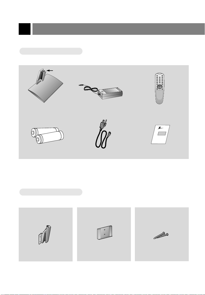
Accessories
Accessories
Hole
Table style stand AC Adaptor Remote Control
1.5V
1.5V
Batteries Power cord Operating guide
Optional extra
Optional extra
* Contact your dealer for buying this optional item.
power
tv/video
cc
flashbk
menu
mute
ch
vol vol
enter
sleep
ch
Zenith
AS mark
10
Wall mount
Wall mounting bracket
Screws
206-3652
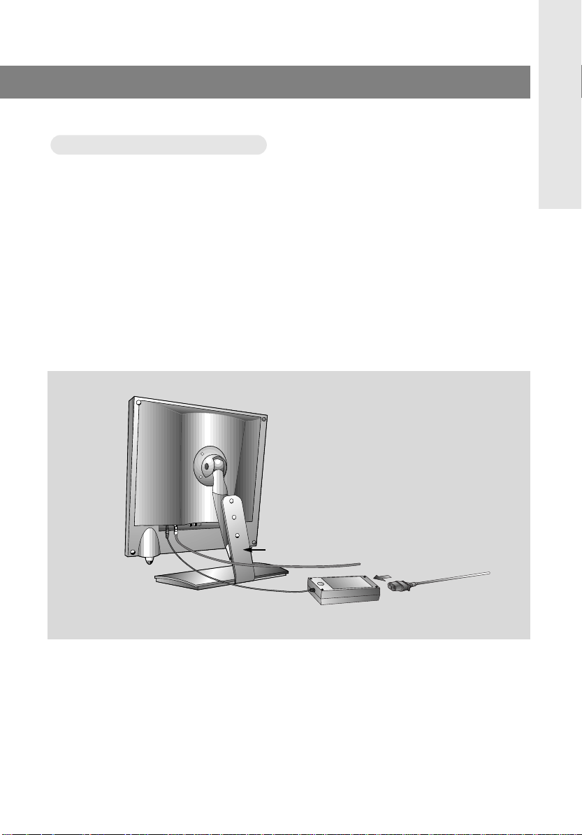
atching
WWatching
* Please make sure to connect the power plug to the wall outlet socket after connecting the TV to the adaptor.
a. Install the LCD TV in the correct using the installation accessories. Refer to page 12, 13.
b. Connect the antenna cable to the antenna input port of the set.
c. Connect the adaptor to the power input port of the set.
d. Connect the power plug to the wall outlet socket after connecting the power cord to the adaptor.
TV programs
TV programs
INTRODUCTION
206-3652
a
c
b
d
11

Basic composition of LCD TV
* You can install the set on the wall with wall installer as well as on the table.
* To reduce the risk of injury from falling, this product should be secured at all times.
Installations
Installations
1
Installation on the wall
* Don’t install the set on a weak wall surface such as plaster or form board.
a
a. Fix the wall mounting bracket with two screws in the position you wish to install the set.
These wall mount and wall mounting bracket, screws are optional items.
b. Put the wall mount on the wall mounting bracket.
c. Put the set on the wall mount.
12
b
c
206-3652

2
Installation on the table
INTRODUCTION
enter vol vol
power
menu
tv/video
ch ch
a. Place the table installer in the position you wish to install the set.
b. Put the set in the table installer.
* When you assemble the TV set with table style stand, please match the stick of TV set to the hole of the
table style stand so as not to allow movement of the joint.
206-3652
13
Connecting antenna
DC 12V
ANT IN
+75 Ω
COMPONENT INPUT(4
BP
P
DC 12V
ANT IN
+75 Ω
COMPONENT INPUT(48
BP
P
DC 12V
ANT IN
+75 Ω
COMPONENT INPUT(48
BP
P
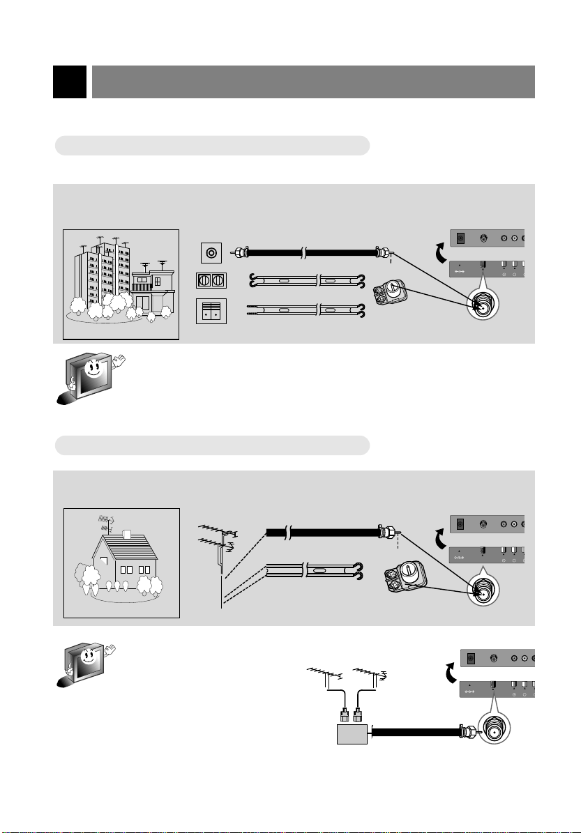
* To get better picture quality, adjust the direction of antenna.
Connecting to wall antenna socket
Connecting to wall antenna socket
● In case of wall antenna socket in apartment houses, connect the antenna cable as shown below.
(Use the correct type of antenna cable to the type of wall antenna socket.)
Turn clock arise to
tighten.
75Ω round cable
300Ω flat cable
Apartments
* In case of 75Ω round cable, insert the bronze wire and then tighten the connecting nut.
And in case of 300Ω flat cable, connect the twisted wire to the antenna converter and
then connect the converter to the antenna input port.
* When using 75Ω round cable, do not bend bronze. It may cause poor picture quality.
Connecting to outdoor antenna
Connecting to outdoor antenna
wall connecting port
● This type of antenna is usually used at common private houses.
VHF antenna
UHF
antenna
75Ω round cable
300Ω flat cable
Private house
* In poor signal area, you can get better
picture quality if you install the antenna like the figure as shown right.
* If an antenna is divided to two TV
sets, use “signal divider” for connecting.
VHF
bronze wire
antenna
converter
Turn clock arise to
tighten.
bronze wire
antenna
converter
UHF
antenna input port
antenna input port
signal
amplifier
206-3652
14
Connecting external equipment
* TV screen is automatically converted to TV mode by pressing the channel (D,E) buttons, flashbk or number
buttons (0~9) when using VIDEO.
* Please connect to other AV equipment by using input ports of the set.
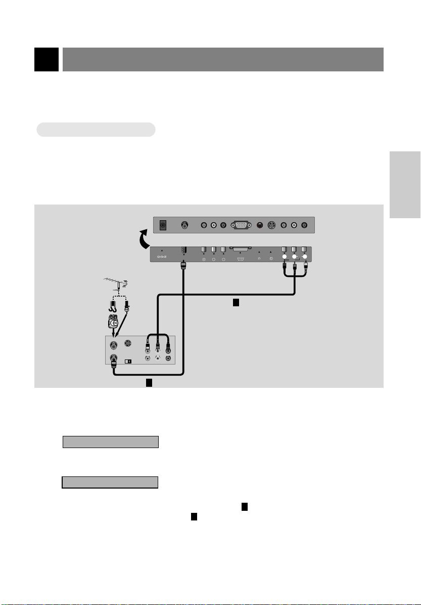
Connecting VCR
Connecting VCR
How to connect
1
● Connect the audio/video output ports of VCR to the corresponding input ports of the set.
PC/D-TV INPUTPC/D-TV INPUT EARPHONEEARPHONE S-VIDEOS-VIDEO
Antenna cable
shapes
Antenna
converter
< Back panel of VCR >
ANT IN
ANT OUT
or
S-VIDEO
CH3
Direct
connection
OUT
IN
CH4
AUDIO VIDEO
(R) (L)
COMPONENT INPUTCOMPONENT INPUT
DC 12V
ANT IN
COMPONENT INPUT(480i)
+75 Ω
PC/D-TV INPUT
R
P
P
R
P
B
2
S-VIDEO INPUT
H/P
RRVIDEOVIDEO
AUDIOAUDIO
MONOMONO
INPUTINPUT
(MONO)
RLVIDEOINAUDIO
CONNECTION
1
How to use
2
Watching TV programs
Turn the set on and select the channel you want.
Watching VCR
a. Press tv/video button of the remote control to select [VIDEO].
* Select the channel 3 or 4 if you use only connection .
* Select VIDEO if you use connection .
b. Insert a video tape into the VCR and press the PLAYbutton.
206-3652
2
1
15

Connecting external equipment
tv/video
Only watching external AA
Only watching external
V source
V source
How to connect
1
● Connect the audio/video output ports of external A/V equipment to the corresponding input ports of
the set.
DC 12V
ANT IN
COMPONENT INPUT(480i)
+75 Ω
< TV connection panel >
< Back panel of
external equipment >
B
P
PC/D-TV INPUT H/P
R
P
S-VIDEO INPUT
R
RLVIDEOINAUDIO
(MONO)
Camcorder
Video Game set
L VIDEOAUDIO
CDI
CDGP
VCDP
How to use
2
● Turn the set on and press tv/video button to select [VIDEO].
< On remote control >
● Try this after turning on the external AV equipment.
16
VIDEO
206-3652

Connecting DVD player
tv/video
● Connect component video inputs to Y, PB, PR and audio inputs to right and left port of AV ports.
How to connect
1
DC 12V
< TV connection panel >
< Back panel of DVD >
ANT IN
+75 Ω
COMPONENT INPUT(480i)
P
B
AUDIO
R
L
How to use
2
● Turn the set on and press tv/video button to select [DVD].
PC/D-TV INPUT S-VIDEO INPUT
R
P
H/P
DVD
VIDEOINRL AUDIO
(MONO)
CONNECTION
206-3652
< On remote control >
● Try this after turning on the DVD set.
17
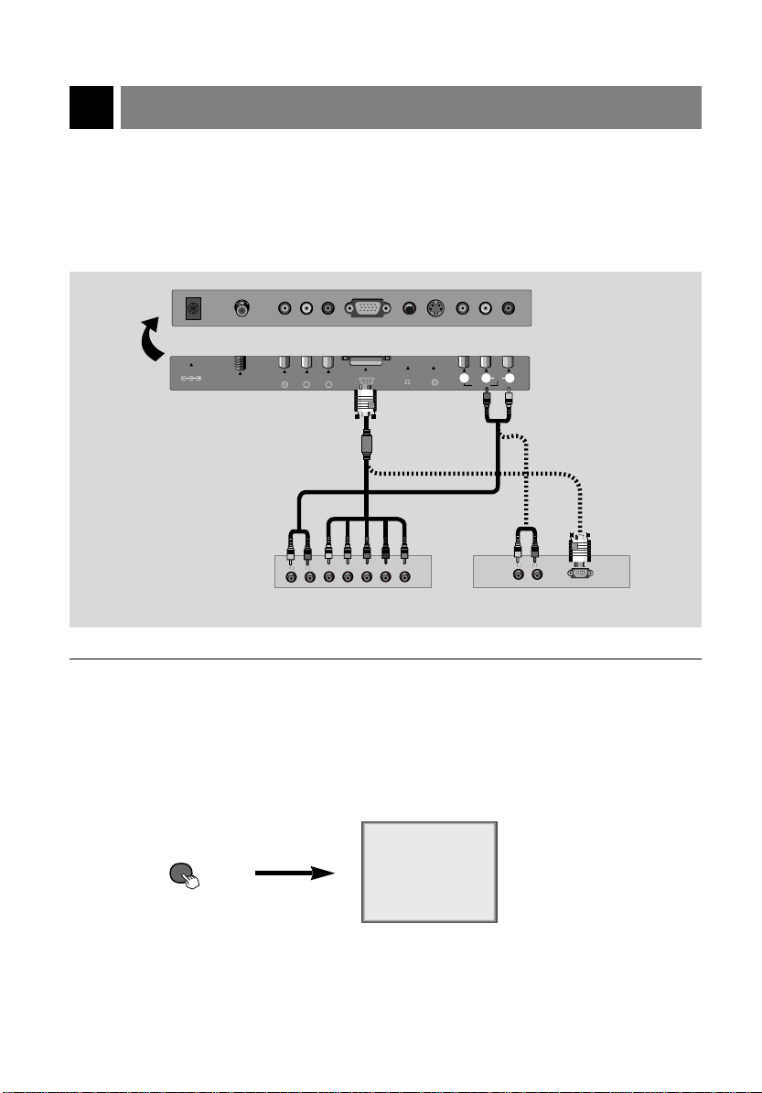
Connecting DTV
tv/video
* Make sure to select PC mode before operating.
How to connect
1
DC 12V
ANT IN
+75 Ω
COMPONENT INPUT(480i)
PC/D-TV INPUT S-VIDEO INPUT
B
R
P
P
< TV connection panel >
AUDIOAUDIO
RR
LL
H V R G B
How to use
2
● Turn the set on and press tv/video button to select [PC].
H/P
VIDEOINAUDIO
(MONO)
or
< Back panel of DTV >
PC
RL
AUDIO
L
R
< On remote control >
● Try this after turning on the DTV set.
206-3652
18

Connecting PC as monitor
* Make sure to select PC mode on before operating.
How to connect
1
● Make sure to set resolution of the PC to be available before connecting. Refer to page 20.
● Connect the set to the PC with PC signal cable.
● Connect the audio ports to the PC to get PC sound.
CONNECTION
DC 12V
ANT IN
+75 Ω
< TV connection panel >
206-3652
COMPONENT INPUT(480i)
BPPR
PC/D-TV INPUT
S-VIDEO INPUT
H/P
VIDEO
(MONO)
AUDIO
RL
IN
< PC >
19

Connecting PC as monitor
tv/video
MODE Resolution Horizontal Vertical
Frequency(KHz) Frequency(Hz)
640x480
640x480
656x496
640x480
640x480
720x400
800x600
800x600
800x600
800x600
800x600
832x624
1024x768
1024x768
1024x768
VGA
SVGA
(MAC)
XGA
31.5KHz
35KHz
37.9KHz
37.5KHz
43.3KHz
31.5KHz
35.2KHz
37.9KHz
48.1KHz
46.9KHz
53.7KHz
49.7KHz
48.4KHz
56.5KHz
60.2KHz
60Hz
67Hz
72Hz
75Hz
85Hz
70Hz
56Hz
60Hz
72Hz
75Hz
85Hz
75Hz
60Hz
70Hz
75Hz
Displayable Monitor Specification
Displayable Monitor Specification
How to use
2
● Turn the set on and press tv/video button to select [PC].
< On remote control >
● Try this after turning on the PC.
PC
20
206-3652

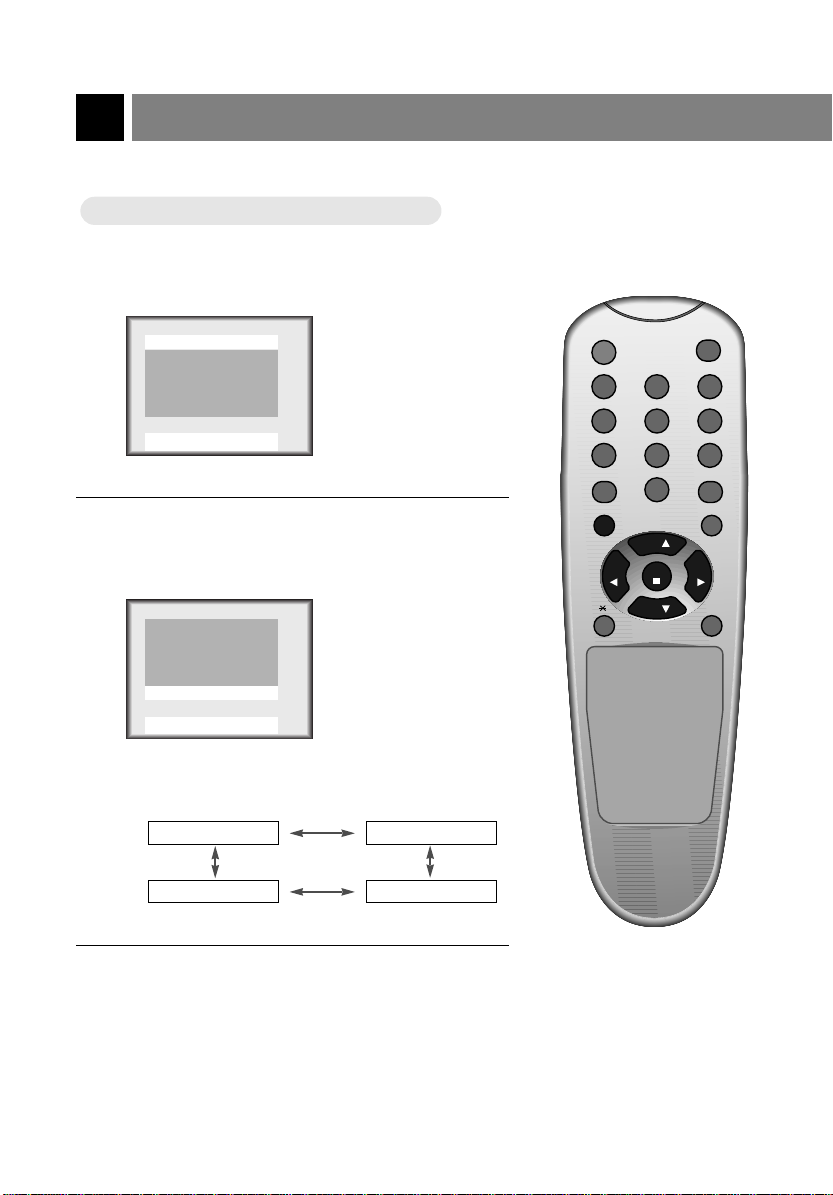
Function checking in PC mode
* Make sure to select PC mode on before operating.
Press the menu button. Each time you press the button you can see menus as below.
1
Language English
Use
And
FFGG
A
Clock Set --:--AM
Sleep Timer Off
On Time
Off Time
On/Off Timer Off
Use
DDEEFFGG
And
--:--AM
--:--AM
A
Clock : 31
Phase : 31
HPOS : 22
VPOS : 50
Reset
Use
Contrast 60
Brightness 90
Use
Treble 50
Bass 50
Balance 0
Use
DDEEFFGG
DDEEFFGG
DDEEFFGG
And
And
And
A
A
A
PC
CONNECTION
Press the channel (
2
206-3652
) buttons to select a function you want to use.
D,E
21

tv/video
menu
enter vol vol
ch ch
power
Using remote control
power
flashbk
menu
mute
sleep
ch
enter
vol vol
ch
cc
tv/video
Inserting batteries
Inserting batteries
Pull the battery cover
upward in the arrow
1
direction to remove.
Insert the batteries
with correct polarity.
2
Replace the battery
compartment cover.
3
* Apply two 1.5V alkaline batteries of AAA type. Don’t mix the used batteries with new bat-
teries.
* Remove batteries when you don’t use the remote control for long time. Liquid leakage from
old battery may cause operation failure.
Notes for using remote control
Notes for using remote control
Make sure these are no
objects between the
remote control and its sensor.
Don’t place the remote control
near a heater or damp place.
Strong impact on remote control may cause operation failure.
remote control
sensor
Signal from the remote control may be disturbed by sun
light or other strong light. In
this case, turn the set to other
direction.
22
206-3652

Turning on the set
power
flashbk
menu
mute
sleep
ch
enter
vol vol
ch
cc
tv/video
0
2 3
5 64
8 97
1
* First, connect antenna cable and power cord with the adaptor.
* Press the power button and you will get stable picture and sound in a few seconds.
Press the power button to turn the set on.
1
displayed only in
stereo signal
channel number
ST. 7
displayed only if present
2
time display is set
Press the channel (
a channel you want after memorizing received broadcasting signals in the local area.
● Direct selecting channels
Press number of the program as one or two digits with
number buttons.
ex: channel 7 7 or 07
● Refer to page 32 ~ 33 to memorize channels.
) or number buttons to select
D,E
Adjust Volume level.
3
● Volume (G) button increas-
es the level of sound.
● Volume (F) button decreas-
es the level of sound.
Volume 3
12:30 PM
BASIC
FUNCTIONS
206-3652
23

Function checking in TV mode
Press the menu button. Each time you press the button you can see menus shown
below.
1
Language English
Captions Off
Caption/Text CC1
Parental Ctl
Use
Clock Set --:--AM
Sleep Timer Off
On Time
Off Time
On/Off Timer Off
Use
DDEEFFGG
DDEEFFGG
And
And
A
--:--AM
--:--AM
A
EZ Program
Channel Add/Del
Use
Contrast 100
Brightness 100
Color 85
Tint 0
Sharpness 7
APC Clear
Use
Treble 50
Bass 50
Balance 0
MTS Mono
Use
DDEEFFGG
DDEEFFGG
DDEEFFGG
And
And
A
And
A
A
Press the channel (
2
24
) buttons to select a function you want to use.
D,E
206-3652

Setting language
Language
Language
Press the menu button to select the
screen display as below.
1
Language English
Captions Off
Caption/Text CC1
Parental Ctl
Use
Press the channel (
select a language you want to adjust.
2
Language English
Captions Off
Caption/Text CC1
Parental Ctl
Use
● Each press of volume (F, G) buttons
changes the screen display as below.
English
DDEEFFGG
DDEEFFGG
And
And
A
D,E
A
Español
Press the enter (A) button.
3
) buttons to
BASIC
FUNCTIONS
Français
206-3652
25

Closed caption function
Closed captioning is a process which converts the audio portion of a television program into written words which
then appear on the television screen in a form similar to subtitles. Closed captions allow viewers to read the dialogue and narration of television programs.
Using Closed Captions
Captions are the subtitles of the dialogue and narration of television programs. For prerecorded programs, program dialogue can
be arranged into captions in advance. It’s possible to caption a
live program by using a process called real-time captioning, which
creates captions instantly. Real-time captioning is normally done
by professional reporters using a machine shorthand system and
computer for translation into English.
FOLLOW ME
Caption Tips
• Not all TV broadcasts include closed caption signals.
• Sometimes TV stations broadcast four different caption signals on the same channel. By selecting From
CC1 to CC4
Another mode might show demonstration or programming information.
• Your TV might not receive caption signals normally in the following situations.
Poor reception conditions are encountered:
• IGNITION:
Picture may flutter, drift, suffer from black spots or horizontal streaking. Usually caused by interference from
automobile ignition systems, neon lamps, electrical drills, and other electrical appliances.
• GHOSTS:
Ghosts are caused when the TV signal splits and follows two paths. One is the direct path and the other is
reflected off tall buildings, hills or other objects. Changing the direction or position of the antenna may
improve reception.
• SNOW:
If your receiver is located at the weak, fringe area of a TV signal, your picture may be marred by small dots.
It may be necessary to install a special antenna to improve the picture.
An old, bad, or illegally recorded tape is played.
Strong, random signals from a car or airplane interfere with the TV signal.
The signal from the antenna is weak.
The program wasn’t captioned when it was produced, transmitted, or taped.
, you can choose which signal you view. CC1 is usually the signal with the captions, while
Captioning is an effective system for the hearing-impaired, and it
can also aid in teaching language skills.
• The picture at left shows a typical caption.
26
206-3652

Operating the Caption
Operating the Caption
Press the menu button to select the
screen display as below.
1
Language English
Captions Off
Caption/Text CC1
Parental Ctl
Use
Press the channel (
select [
2
Language English
Captions Off
Caption/Text CC1
Parental Ctl
Use
And
DDEEFFGG
A
Caption/Text
And
DDEEFFGG
A
D,E
].
Press the volume ( G) button.
3
) buttons to
● Each time you press the volume (
the caption mode is displayed one by one as
shown below.
CAPTION CC1
CAPTION CC2
CAPTION CC3
CAPTION CC4
CAPTION TEXT1
CAPTION TEXT2
CAPTION TEXT3
CAPTION TEXT4
F, G
) buttons,
BASIC
FUNCTIONS
206-3652
Language English
Captions Off
Caption/Text CC1
Parental Ctl
Use
DDEEFFGG
And
A
Press the enter (A) button.
4
● This TV is programmed to remember which
mode it was last set to, even if you switch the
POWER off.
27

Closed caption function
Operating the Caption
Operating the Caption
Press the cc button to select
1
[
Captions
].
Captions Off
Use
And
FFGG
A
Press the volume (
2
● Each press of volume (
Off On
● Captions function setting is Completed.
28
F, G
) buttons to select [On] and press the enter (A) button.
) buttons changes the screen display as below.
F, G
EZ Mute
206-3652

Using the TT
Using the
Text services give a wide variety of information on
all kind of subjects (ex. captioned program lists,
weather forecasts, stock exchange topics, news
for hearing-impaired—-) through the half TV
screen.
But not all stations offer text services, even
though they might offer captioning.
Repeat the steps 1-2 at page 27.
ext Function
ext Function
1
VGE 1033 Closed Caption
Calibrated Distortion Unit
Text mode
Green text
Green underline
Green Italics
Press the volume (
) buttons to select [Text 1], [Text 2], [Text 3] or [Text 4].
F, G
2
Language English
Captions Off
Caption/Text Text1
Parental Ctl
Use
Press the enter (A) button.
DDEEFFGG
And
A
3
● In the event you receive a poor signal, an empty black box may appear and disappear, even when the text
mode is selected. This is normal function in such an event.
206-3652
BASIC
FUNCTIONS
29

Parental control function
The Parental Control Function (V-Chip) is used to block program viewing based on the ratings sent by the
broadcast station. The default setting is to allow all programs to be viewed. Viewing can be blocked by the
type of program and by the categories chosen to be blocked. It is also possible to block all program viewing
for a time period. To use the Parental Control Function, the following must be set :
1. Ratings and categories to be blocked.
2. Number of hours to lock the television viewing control
3. Set a password
4. Enable the lock
V-Chip rating and categories
Rating guidelines are provided by broadcast stations. Most television programs and television movies can
be blocked by TV Rating and/or Individual Categories. Movies that have been shown at the theaters or
direct-to-video movies use the Movie Rating System(MPAA) only.
For Movies previously shown in theaters:
Movie Ratings:
* Unblocked
* G and Above (general audience)
* PG and Above (parental guidance suggested)
* PG-13 and Above (13 years and up)
* R and Above (restricted)
* NC-17 and Above (18 years and up)
* X (adult)
If you set PG-13 and Above ; G and PG movies will be available, PG-13, R, NC-17 and X will be
blocked.
For Television programs including made-for-TV movies:
General TV Ratings:
* Unblocked
* TV-G and Above (general audience) (individual categories do not apply)
* TV-PG and Above (parental guidance suggested)
* TV-14 and Above (14 years and up)
* TV-MA (mature audience)
Children TV Ratings:
* Unblocked
* TV-Y and Above (youth) (individual content categories do not apply)
* TV-Y7 (youth, 7 years and up)
Content Categories:
* Dialog - sexual dialogue (applies to TV-PG and Above, TV-14 and Above)
* Language - adult language (applies to TV-PG and Above, TV-14 and Above, TV-MA)
* Sex scenes - sexual situations (applies to TV-PG and Above, TV-14 and Above, TV-MA)
* Violence (applies to TV-PG, TV-14 and TV-MA)
* F Violence - fantasy violence (applies only to TV-Y7)
* No Rating (blocks all viewing)
30
206-3652

Setting up Blocking
Setting up Blocking
Press the menu button to select the
screen display as below.
1
Language English
Captions Off
Caption/Text CC1
Parental Ctl
Use
Press the channel (
select [
2
Language English
Captions Off
Caption/Text CC1
Parental Ctl
Use
Press the volume ( G) button.
And
DDEEFFGG
Parental Ctl
And
DDEEFFGG
A
D,E
].
A
3
Aux. Block
MPAA
Age Block
Content Blk
Set Hours 00 Hours
Set Password
Lock On/Off Must Set Hours
Use
DDEEFFGG
Sources Unblocked
Unblocked
To Set
FFGG
And
A
) buttons to
Press the channel (
select the types of blocking to be set.
4
Press the volume (
select the types of ratings to block.
● [MPAA], [Age] and/or [Content block] may
be set.
Press the menu button to return from
[Age Block] or [Content Blk] setting
screens.
Press the channel (
select [Set Hours].
5
Press the volume (
set the number of hours for the blocking.(Up to 99)
Press the channel (
select [Set Password].
Enter a four digit password. Enter it
again when requested.
● Anew password may be chosen each time
blocking is set up.
Press the channel (
select [Lock On/Off].
6
Press the volume (
set the lock [On].
Press the menu button to save the
blocking setup and exit.
D,E
F, G
D,E
F, G
D,E
D,E
F, G
) buttons to
) buttons to
) buttons to
) buttons to
) buttons to
BASIC
FUNCTIONS
) buttons to
) buttons to
● If parental control is already set then enter
the password when requested.
206-3652
31

Programming / Erasing channels
0
2 31
5 64
8 97
power
flashbk
menu
mute
sleep
ch
enter
vol vol
ch
cc
tv/video
Auto programming channels
Auto programming channels
* This function can be operated only when the set can receive input sig-
nal from broadcasting stations and the antenna cable is connected.
*[Auto programming] function memorizes all the receiving channels of
terestrial TV signals or cable TV programs.
*If channels of general wireless TV and cable TV are duplicated,
press the number buttons (0 ~ 9) to change as
general wireless TV Cable TV
Press the menu button to select the screen display
as below.
1
EZ Program
Channel Add/Del
Use
DDEEFFGG
And
Press the volume (G) button.
2
EZ Program
TV 7
A
.
Memorizing channel number is displayed.
32
Stop b
* Press the channel (
rized channels after auto programming is finished.
* If you press the enter (A) button in auto program-
ming, the function will stop and only channels programming up to that time will remain.
* Auto programming function can memorize only the
channels which are being received at that time.
) buttons to check the memo-
D,E
206-3652

Right master page
Memorizing /
Memorizing /
* You can select [Add] or [Del] for the current channel.
Press the menu button to select the
screen display as below. Then press
1
the channel (
[Channel Add / Del ].
EZ Program
Channel Add/Del
Use
DDEEFFGG
Press the volume (
Erasing current channel
Erasing current channel
) buttons to select
D,E
And
A
) buttons.
F, G
2
Press the channel (
select a channel you want and then
3
press the volume (
select [Added] or [ Deleted ].
Channel Add/Del
TV 7 Added
Use
DDEEFFGG
● Each time you press the volume (
tons, you can select as below alternatively.
Added
And
D,E
F, G
A
Deleted
) buttons to
) buttons to
Deleted
) but-
F,G
BASIC
FUNCTIONS
The current channel number is displayed.
Channel Add/Del
TV 7 Added
Use
206-3652
DDEEFFGG
And
A
Press the enter (A) button.
4
● The current channel is to be added /
deleted.
33

Setting current time
0
2 31
5 64
8 97
power
flashbk
menu
mute
sleep
ch
enter
vol vol
ch
cc
tv/video
* If current time setting is erased by power failure or TV is unplugged, reset it.
o set current time as 10:30 AMAM
TTo set current time as 10:30
Press the menu button to select the screen display
as below.
1
Clock Set --:--AM
2
Sleep Timer Off
On Time
Off Time
On/Off Timer Off
Use
DDEEFFGG
Press the channel (
Set].
Clock Set --:--AM
Sleep Timer Off
On Time
Off Time
On/Off Timer Off
And
--:--AM
--:--AM
A
--:--AM
--:--AM
) buttons to select [Clock
D,E
Use
DDEEFFGG
And
Press the volume ( G) button.
3
Clock Set 00:00AM
34
Sleep Timer Off
On Time
Off Time
On/Off Timer Off
Use
FFGG DDEE
And
--:--AM
--:--AM
A
A
206-3652

Press the channel (
select current hour.
4
●If you hold the Dbutton, the hour display is
changed in the sequence of AM 1 ➔ AM 2
➔ ....PM12 ➔ PM 1 .... ➔ AM 12, and
changed in the reverse sequence for Ebutton.
● Select [AM 10].
D,E
) buttons to
To check current channel, time and
sound status (stereo or dual)
● Press the enter (A) button.
ST.SAP 7
current channel
Press the volume ( G) button.
5
Clock Set 10:00AM
Sleep Timer Off
On Time
Off Time
On/Off Timer Off
Use
FFGG DDEE
Press the channel (
select current minute. And press the
6
enter (
● If you hold the Dbutton, the minute display
is changed in the sequence of 00 ➔ 01 ➔ 02
...58 ➔ 59, and changed in the reverse
sequence for Ebutton.
● Select [30] and press the enter (A) button
to complete the setting.
● Time is progressed from the point of pressing the enter (A) button.
● Press the enter (A) button again and the
screen display is disappears.
206-3652
) button.
A
And
--:--AM
--:--AM
A
D,E
) buttons to
current sound
status
10:30AM
● Press the enter (A) button again to release.
* Current time is not displayed if current
time is not set.
* Stereo or dual sound is displayed only
when receiving the correspondent input
signal.
* Above displays disappear after a few sec-
onds.
current time
35
CLOCK
SETTING

Setting Off-Timer function
0
2 31
5 64
8 97
power
flashbk
menu
mute
sleep
ch
enter
vol vol
ch
cc
tv/video
*Timer function can be operated only if current time has been already set.
*Off-timer function is prior to on-timer function if they are set to the same time.
TTurning of
1
2
urning of
f at 1
1:30 PM by of
f at 1
1:30 PM by of
f-timer function
f-timer function
Press the menu button to select the screen display
as below.
Clock Set 10:30AM
Sleep Timer Off
On Time
Off Time
On/Off Timer Off
Use
DDEEFFGG
Press the channel (
Time].
Clock Set 10:30AM
Sleep Timer Off
On Time
Off Time
On/Off Timer Off
Use
DDEEFFGG
And
And
--:--AM
--:--AM
A
--:--AM
--:--AM
A
) buttons to select [Off
D,E
Press the volume (G) button.
3
Clock Set 10:30AM
Sleep Timer Off
On Time
Off Time
On/Off Timer Off
Use
36
FFGG DDEE
And
--:--AM
--:--AM
A
206-3652

Press the channel (
select hour you want to set.
4
● If you hold the Dbutton, the hour display
is changed in the sequence of AM 1 ➔ AM
2 ➔ ....PM12 ➔ PM 1 .... ➔ AM 12, and
changed in the reverse sequence for
button.
● Select [PM 11].
Press the volume (G) button.
D,E
5
) buttons to
Press the enter (A) button.
7
E
Press the channel (
select [On/Off Timer].
8
Clock Set 10:30AM
Sleep Timer Off
On Time
Off Time
On/Off Timer Off
--:--AM
11:30PM
) buttons to
D,E
Clock Set 10:30AM
Sleep Timer Off
On Time
Off Time
On/Off Timer Off
Use
FFGG DDEE
Press the channel (
select minute you want to set.
And
--:--AM
11:00PM
A
D,E
6
● If you hold the Dbutton, the minute dis-
play is changed in the sequence of 00 ➔
01 ➔ 02 ...58 ➔ 59, and changed in the
reverse sequence for Ebutton.
● Select [30].
206-3652
) buttons to
Use
Press the volume (G) button to select
[On] and press the
9
● Each press of volume (G) button changes
the screen display as below.
● The screen display will disappear if you
press the enter (A) button once more.
● The screen display of [ Sleep ] appears
on the screen for one minute untill TV
automatically turns off.
And
DDEEFFGG
On Off
A
enter (
) button.
A
37
CLOCK
SETTING

Setting On-Timer function
*Timer function can be operated only if current time has been already set.
urning on at 7:10
TTurning on at 7:10
AM with volume 40 on channel 8 by on-timer function
AM with volume 40 on channel 8 by on-timer function
Press the menu button to select the
screen display as below.
1
Clock Set 10:30AM
Sleep Timer Off
On Time
Off Time
On/Off Timer Off
Use
DDEEFFGG
Press the channel (
select [On Time].
2
Clock Set 10:30AM
Sleep Timer Off
On Time
Off Time
On/Off Timer Off
Use
DDEEFFGG
And
And
--:--AM
11:30PM
A
--:--AM
11:30PM
A
D,E
) buttons to
Press the channel (
select hour you want.
4
● If you hold the Dbutton, the hour display
is changed in the sequence of AM 1 ➔ AM
2 ➔ ....PM12 ➔ PM 1 .... ➔ AM 12, and
changed in the reverse sequence for
button.
● Select [AM 7].
D,E
Press the volume (G) button.
5
Clock Set 10:30AM
Sleep Timer Off
On Time
Off Time
On/Off Timer Off
Use
FFGG DDEE
7:00AM
11:30PM
And
A
) buttons to
E
Press the volume (G) button.
3
Clock Set 10:30AM
Sleep Timer Off
On Time
Off Time
On/Off Timer Off
Use
38
FFGG DDEE
And
--:--AM
11:30PM
A
Press the channel (
select minute you want.
6
● If you hold the Dbutton, the minute display
is changed in the sequence of 00 ➔ 01 ➔
02 ...58 ➔ 59, and changed in the reverse
sequence for Ebutton.
● Select [10].
D,E
) buttons to
206-3652

Press the enter (A) button.
7
9
Press the volume (
F, G
) buttons to
select [On] and press the
(A) button.
enter
Clock Set 10:30AM
Sleep Timer Off
On Time
Off Time
On/Off Timer Off
Use
Press the channel (
select [On/Off Timer].
8
Clock Set 10:30AM
Sleep Timer Off
On Time
Off Time
On/Off Timer Off
Use
DDEEFFGG
DDEEFFGG
And
And
7:10AM
11:30PM
A
7:10AM
11:30PM
A
) buttons to
D,E
● Each press of volume (
changes the screen display as below.
F, G
) buttons
On Off
● On-Timer function setting is completed.
● If you press the enter (A) button once
more, the screen display disappear
and the set will be turned automatically on with volume level 40 on channel
8 at 7:10 AM.
CLOCK
SETTING
206-3652
* If on-timer function is active, the current channel will change to the set channel when on-timer
is activated.
* Unless any button is pressed within two hours after turning on the TV by on-timer function, the
set is automatically turned off.
39

Setting sleep time function
0
2 31
5 64
8 97
power
flashbk
menu
mute
sleep
ch
enter
vol vol
ch
cc
tv/video
* This function will automatically turn the set off after a set time.
Press the sleep button to set sleep time function.
1
● Each press of the button changes setting time status as
below.
Sleep
Use
FFGG
--And
A
40
- - -
10
240
180
120 90
● To release sleep time setting, press the sleep button
repeatedly to select [ --- ].
● The screen display of [ Sleep ] appears on the screen for
one minute untill automatically turning off.
* When a sleep time you want is displayed on the
screen, don’t press the sleep button. The screen
display disappears and sleep time is to be set.
* To check remaining sleep time after setting, press
the sleep button just once.
* To change sleep time setting, press the sleep
button repeatedly to select time setting you want.
* If you turn the set off after setting sleep time, the
setting will be erased. Set it again.
20
30
60
206-3652

Adjusting audio condition
Adjusting audio condition by user
Adjusting audio condition by user
Press the menu button to select the
screen display as below.
1
Treble 50
Bass 50
Balance 0
MTS Mono
Use
Press the channel (
select a audio item you want to adjust.
2
DDEEFFGG
And
A
D,E
) buttons to
Press the volume (
adjust the audio condition as you want.
3
Treble 50
Bass 50
Balance 0
MTS Mono
Use
DDEEFFGG
Press the enter (A) button.
And
F, G
A
4
) buttons to
CLOCK
SETTING
206-3652
41

Adjusting audio condition
Selecting bilingual signals
Selecting bilingual signals
Screen display in stereo signal : Stereo
Screen display in bilingual signal : SAP
* Bilingual (dual language) signal
● This signal contains the secondary language signal in addition to the primary language.
● There are the primary and secondary language and stereo modes in bilingual signal.
● [Mono] : The primary language is output from left and right speaker. Signal mode is mono.
● [Stereo] : The primary language is output from left and right speaker. Signal mode is stereo.
● [SAP] : The secondary language is output from left and right speaker.
Press the menu button to select the
screen display as below.
1
Treble 50
Bass 50
Balance 0
MTS Mono
Use
Press the channel (
select [MTS].
2
42
And
DDEEFFGG
* If some strange sound is heard when watching TV programs on stereo mode in poor signal
* [Stereo] or [Mono] mode can be available only when broadcasting signal contains the data.
A
D,E
areas, or if in non-dual signal service area, make sure to select mono mode.
) buttons to
Press the volume (
select an audio mode you want.
3
Treble 50
Bass 50
Balance 0
MTS Mono
Use
● Each press of volume (F, G) buttons
changes the screen display as below.
Press the enter (A) button.
DDEEFFGG
Mono
And
A
Stereo
4
) buttons to
F, G
SAP
206-3652

PC/D-TV INPUT
S-VIDEO INPUT
H/P
LVIDEOINA
(MONO)
BPPR
Mute
Mute
* This function cuts of f speaker sound. It’s convenient when getting phone
calls.
Press the mute button.
1
Mute
● To release muted sound, press the mute button or volume
(
) buttons.
F, G
● If muted sound is released, volume level is displayed on the
screen.
Using headphone
Using headphone
● Headphone is an optional item.
●You can adjust headphone sound with volume(
are listening to sound through headphone, speaker sound is cut off.
) buttons. While you
F, G
power
flashbk
menu
ch
vol vol
enter
ch
tv/video
2 31
5 64
8 97
cc
0
mute
sleep
206-3652
AUDIO /
VIDEO
43
Adjusting video condition
0
2 31
5 64
8 97
power
flashbk
menu
mute
sleep
ch
enter
vol vol
ch
cc
tv/video
APC (Auto Picture Control)
APC (Auto Picture Control)
Press the menu button to select the screen display
as below.
1
Contrast 100
Brightness 100
Color 85
Tint 0
Sharpness 7
APC Clear
2
Use
Press the channel (
Contrast 100
Brightness 100
Color 85
Tint 0
Sharpness 7
APC Clear
Use
DDEEFFGG
DDEEFFGG
And
And
A
) buttons to select [APC].
D,E
A
● Each press of volume (
display as below.
Clear Optimum
Off Soft
Press the enter (A) button.
3
44
) buttons changes the screen
F,G
206-3652

Manual picture control
Manual picture control
Press the menu button to select the
screen display as below.
1
Contrast 100
Brightness 100
Color 85
Tint 0
Sharpness 7
APC Clear
Use
Press the channel (
select a picture item you want to adjust.
2
DDEEFFGG
And
A
D,E
) buttons to
Press the volume (
adjust the picture condition as you
3
want.
Contrast 100
Brightness 100
Color 85
Tint 0
Sharpness 7
APC Clear
Use
DDEEFFGG
● [Contrast], [Brightness], [Color] are adjusted from 0 to 100.
● [Tint] is adjusted from Red 50 to Green 50.
● [Sharpness] is adjusted from 0 to 10.
Press the enter (A) button.
And
F, G
A
4
) buttons to
206-3652
* APC setting is to be released if you use this function.
45
AUDIO /
VIDEO

Product specifications
Model : ZLD15A1
Main body : Horizontal size (mm) : 394
Height (mm) : 384
Thickness (mm) : 105.5
Weight (kg) : 5.2
Including table stand : Horizontal size (mm) : 394
Height (mm) : 413
Thickness (mm) : 194
Weight (kg) : 7.9
Power requirements : DC 12V/3A
Television system : NTSC
Television channels : VHF : 2 ~ 13, UHF : 14 ~ 69
Tube : LCD Panel
Power consumption : See the back of the set
External antenna impedance : 75 Ω
Audio output : 1.0W + 1.0W
Speaker outputs : 8 Ω X 2
External input ports : VIDEO input port set 1
Adaptor (DC power) : In : AC 100-240V ~ 1.3A-0.7A
: Cable : 01 ~ 125
S-VIDEO input 1
Headphone jack 1
PC/D-TV input 1
Component video input set 1
Power input 1
Antenna input 1
50/60Hz, 85VA
Out : DC 12V, 3A
46
206-3652

Memo
206-3652

Your Zenith Limited Warranty
Direct-View Color TV
ZENITH RESPONSIBILITY
Service Labor During a period of one year from effective warranty date, Zenith will provide service labor by a
Parts New or remanufactured replacements for factory-defective parts will be supplied by a Zenith
Home Service Warranty service for 21” diagonal (U.S.A.) or larger screen size models is provided in the home
Not Covered This warranty covers manufacturing defects and does not cover installation, adjustment of cus-
OWNER’S RESPONSIBILITY
Effective Warranty Date Warranty begins on the date of original consumer purchase. For your convenience, keep the
Operating Guide Read your Operating Guide carefully so that you will understand the operation of your set and
Antenna Reception problems caused by inadequate home antenna or faulty antenna connections are the
Important Product Registration—Please fill out and mail your Product Registration Card. It is imperative
Warranty Service For warranty service, contact Zenith at 1-800-984-9349. Parts and service labor that are
Welcome into the Zenith family! We believe that you will be pleased with your new Zenith
Entertainment Machine. Please read this warranty carefully, it is a “LIMITED WARRANTY” as
defined under Federal Law. This warranty gives you specific legal rights, and you may also
have other rights that vary from state to state within the U.S.A.
Zenith authorized service center when needed as determined by Zenith, as a result of manufacturing defects. This applies only in the U.S.
authorized service center for one year from effective warranty date. Such replacement parts are
warranted for the remaining portion of the original warranty period.
in most cases. (Some repairs may require the unit to be taken by the servicer to the repair facility and returned, at no additional charge.)
tomer controls in the home, installation or repair of home antenna systems, cable converters or
cable company-supplied equipment; it also does not cover damage due to misuse, abuse, negligence, acts of God or other causes beyond the control of Zenith. Any alteration of the product
after manufacture voids this warranty in its entirety.
THIS WARRANTY IS IN LIEU OF ANY OTHER WARRANTY, EXPRESS OR IMPLIED,
INCLUDING WITHOUT LIMITATION, ANY WARRANTYOF MERCHANTABILITY OR FITNESS FOR A PARTICULAR PURPOSE, AND ZENITH SHALL NOT BE LIABLE FOR ANY
CONSEQUENTIAL, INDIRECT, OR INCIDENTAL DAMAGES OF ANY KIND, INCLUDING
LOST REVENUES OR PROFITS IN CONNECTION WITH THE PRODUCT. SOME STATES
DO NOT ALLOW LIMITATIONS ON HOW LONG AN IMPLIED WARRANTY LASTS OR THE
EXCLUSION OR LIMITATION OF INCIDENTALOR CONSEQUENTIAL DAMAGES, SO THE
ABOVE LIMITATIONS OR EXCLUSIONS MAY NOT APPLY TO YOU.
dealer’s dated bill of sale or delivery ticket as evidence of the purchase date.
how to adjust the customer controls.
owner’s responsibility.
that Zenith know how to reach you promptly if we should discover a safety problem that could
affect you.
Zenith’s responsibility (see above) will be provided without charge. Other service is at the
owner’s expense. If you have any problem in obtaining satisfactory warranty service, call or
write the Zenith Response Center. You must provide the model number, serial number and date
of purchase or date of original installation. Before you ask for warranty service, read
“Maintenance and Troubleshooting” in your operating guide. You might avoid a service call.
P/NO : 3828VA0131F
ZENITH ELECTRONICS CORPORATION
Zenith Response Center
201 James Record Rd., Building 3,
Huntsville, AL 35824
Telephone (800) 984-9349
Mon-Fri, 7:00 a.m.-8:00 p.m. CST
Sat. 8:00 a.m.-5:00 p.m. CST
www.zenith.com
© Copyright 2000, Zenith Electronics Corporation.
ZENITH CONSUMER SERVICES FACTORYOWNED SERVICE CENTERS
801 E. Roosevelt Rd
Lombard, IL 60148
(630)705-2830
Home & Carry-in Service
Television/VCR
Parts and Accessories
PTV/Camcorders
201 James Record Rd.
Building 4
Huntsville, AL 35824
(256) 774-4025
Service Hours:
M-F 8-6, Sat 9-2
Will accept UPS
Shipments
206-3652
 Loading...