

Page 1
Advanced Video Imaging
THE QUALITY GOES IN BEFORE THE NAME C
iAviso para nuestros
clientes de habla hispana:
con_dlte la informaci6n que
aparece al final de estemanual!
Projection Color TV
Surround :Sound
Closed Captions
DB JDOLBYSURROUND J
PRO • LOGIC
recycled paper
50 percent
Return the Product Registration
Card, and your "IV could be free.[
Page 2

WARNING:
TO REDUCE THE RISK OF ELECTRIC SHOCK DO NOT
REMOVE COVER (OR BACK). NO USER SERVICEABLE
PARTS INSIDE. REFER TO QUALIFIED SERVICE
PERSONNEL.
TO PREVENT FIRE OR SHOCK HAZARDS, DO NOT EXPOSE
THIS PRODUCT TO RAIN OR MOISTURE.
The lightning flash with arrowhead symbol, within an equitateral
triangle, is intended to alert the user to the presence of uninsulated
"dangerous voltage" within the product's enclosure that may be of
sufficient magnitude to constitute a risk of electric shock to persons.
The exclamation point within an equilateral triangle is intended to
alert the user to the presence of important operating and maintenance
(servicing) instructions in file literature accompanying the appliance.
Safety Tips
Refer to the "Safety Tips" booklet that came with your
product for important safety considerations.
Note to Cable TV System Installer
This reminder is provided to call the cable TV system
installer's attention to An:icle 820-40 of the NEC that
provides guidelines for proper grounding and, in particular,
specifies that the cable ground shall be connected to the
grounding system of the building, as close to the point of
the cable entry as practical.
Power-Cord Polarization
This product is equipped with a polarized alternating-
current line plug (a plug having one blade wider than the
other.) This plug will fit into the power outlet only one
way. This is a safety feature. If you are unable to insert the
plug fully into the outlet, try reversing the plug. If the plug
should still fail to fit, contact your electrician to replace
yOUroObsoleteoutlet. Do not defeat the safety purpose of
the polarized plug.
CAUTION
To prevent: electric shock, match wide blade of'plug to
wide slot, fully insert.
ATTENTION
Pour 6viter les chocs _lectriques, introduire la lame la plus
large de la fiche dans la borne correspondante de la prise et
pousser ju,;qu'au fond.
Copyright © Zenith Electronics Corporation 1994 rVWA_2
Page 3

CONTENTS
INTRODUCTION
Welcome ......................................... ii
Installation Considerations ........................... ii
CONNECTIONS FOR YOUR TV
Locations of User Items ............................. I-1
Connection Center on Back of TV .................... I-2
Other A/V Jacks on TV ............................. 1-2
Step 1. Make Basic Connection to TV ................. 1-3
Step 2. Make VCR Connections to TV ................. 1-4
Step 3. Make Super-VHS VCR Connections to TV ....... 1-5
Step 4. Make A!V Connections to Auxiliary
A/V Jacks (VIDEO 3 IN or S-VIDEO 2 IN) .......... 1-5
Step 5. Make Connections to Monitor Out Jacks ......... 1-5
Step 6. Make Surround Sound Connections to TV ........ 1-6
Step 7. Make Audio Connection to Stereo Amplifier ...... I-6
THE FIRST TIME YOU OPERATE YOUR TV
Step 1. Connect the Power ........................... 2-1
Step 2. Select Your Viewing Source ................... 2-1
Step 3. Use Auto Program ........................... 2-1
Step 4. Time Functions ............................. 2-1
Step 5. Use Other Options ........................... 2-2
REMOTE CONTROL MODEL SC2400
Operation ........................................ 3-1
Installing Batteries ................................. 3-1
REMOTE CONTROL MODEL MBR3430
Operation ........................................ 4-1
Choose the Operating Mode ......................... 4-1
TV Operations .................................... 4-2
VCR Operations .................................. 4-3
Cable-TV Operations ............................... 4-4
Preparation for Use ................................ 4-5
Installing Batteries ................................. 4-5
Programming Brand Codes .......................... 4-6
TV, VCR and Cable-TV Operating Codes .............. 4-7
QUICK REFERENCE TO ON-SCREEN MENUS
Available Menus .................................. 5-1
Summary of Menu Items ............................ 5-1
Menu Operation Example ........................... 5-3
SOURCE MENU
Source Selection .................................. 6-1
Source Identification ............................... 6-1
SETUP MENU
Auto Program .................................... 7-1
Ch. Add/Del ...................................... 7-1
Ch. Labels ....................................... 7-2
Tuning Band ..................................... 7-3
Auto Tuning ..................................... 7-3
Source ID ........................................ 7-3
Clock Set ........................................ 7-4
Captions ......................................... 7-4
Projo Setup ...................................... 7-5
AUDIO MENU
Bass ............................................ 8-1
Treble ........................................... 8-1
Balance ......................................... 8-1
Audio ........................................... 8-1
Enhancement ..................................... 8-1
VIDEO MENU
Contrast ......................................... 9-1
Brightness ....................................... 9-1
Color ........................................... 9-1
Tint ............................................. 9-1
Sharpness ........................................ 9-!
Color Temp ...................................... 9-1
Video Filter ...................................... 9-1
Auto Flesh ....................................... 9-1
Picture Pref ...................................... 9-1
PIP MENU
Ch. Guide ....................................... 10- l
Ch. Review ..................................... 10-2
PIP Source ...................................... 10-2
PIP Color ....................................... 10-3
PIP Tint ........................................ 10-3
PIP Size ........................................ 10-3
PIP OPERATION AND CONNECTIONS
PIP Overview ................................... 11- I
Typical Connections .............................. 11-1
How to Select Main Picture & PIP Source ............. 11-3
PIP Functions ................................... 11-4
MAINTENANCE AND TROUBLESHOOTING
Caring for Your TV ............................... 12-1
Extended Absence ................................ 12-1
TV Picture Interference ............................ 12-1
Before Calling for Service .......................... 12-2
Product Registration Card
Recommended Accessories For Your Television
Aviso para nuestros clientes de habla hispana
Your Zenith Warranty
HOW TO USE YOUR OPERATING GUIDE
THIS OPERATING GUIDE DESCRIBES A FAMILY OF TV MODELS. SOME MODELS HAVE FEATURES THAT ARE
NOT PROVIDED ON OTHER MODELS, SUCH AS AUXILIARY JACKS OR TWO REMOTE CONTROLS. DIFFERENT
CONTROl, PANELS AND REMOTE CONTROLS MAY BE USED FROM MODEL-TO-MODEL.'REFER TO TIlE APPLI-
CABLE SECTIONS OF THIS OPERATING GUIDE FOR THE FEATURES AND ITEMS PROVIDED WITH YOUR TV.
2739-0 i
Page 4

INTRODUCTION
WELCOME
Welcome into the family of Zenith Color Television owners.
This guide provides instructions on how to operate your new
TV. It is supplemented by a booklet containing Safety Tips.
We urge you to read these publications carefully so that you
will receive full enjoyment from your new Zenith TV for
many years to come.
Your new Zenith projection TV has been designed and built to
give you the very best in quality, features and performance.
There are many regional Zenith distributors and thousands of
distributor-approved Zenith service centers throughout the
U.S., Canada and Mexico who can attend promptly and effec-
tively to ordinary service needs.
If you should have an unusual performance or service problem
that cannot be satisfactorily resolved by your distributor-
approved Zenith service center, contact the regional Zenith dis-
tributor in 3'our area, or write:
Zenith Electronics Corporation
Customer Service Department
1000 Milwaukee Avenue
Glenview, Illinois 60025-2493
Telephone: (847) 391-8752
Mon-Fri, 8:00 a.m. - 4:30 p.m. Central Time
INSTALLATION CONSIDERATIONS
Before you install your TV...
Ventilation -- Proper ventilation keeps your TV
running cool. Air circulates through perforations
in the back and bottom of the cabinet. Do not
block these vents or you will shorten the life of
your TV.
Power Source -- Your TV is designed to operate
on normal household current, 120 volt 60 Hertz AC.
Do not attempt tooperate it on DC current.
Power Cord -- Your power cord has a polarized
plug as required by Underwriters' Laboratories. It
has one regular blade and one wide blade and fits
only one way into a standard electrical outlet. If
the blades will not enter either way, your outlet is
very old and non-standard. A new outlet should be
installed by a qualified electrician.
Safe Operation -- Your TV is manufactured and
tested with your safety in mind. However, unusual
stress caused by dropping or mishandling, expo-
sure to flood, fire, rain or moisture, or accidental
spilling of liquids into the TV, can result in poten-
tial electrical shock or fire hazards. If this hap-
pens, have your TV checked by a service
technician before using it again.
Send the model number, serial number, and ,:late of purchase
or original installation, with a full explanation of the problem
and the service history. We, will welcome the opportunity to
look into your specific question or problem ;and to be of assis-
tance in resolving it promptly.
"ITaemodel and serial numlx'rs of your new TV are located on the
back of the TV cabinet. For your future convenience and protec-
tion, we sug_gest that you rex'ord these number,s here:
Model No.
Serial No.
IVlanufactured under license from D_lby Laboratories Licensing Corporation.
Additionally licensed under Canadi:m patent number 1,037,877. "Dolby",
"Pro Logic" ar,d the double-D symbol are trademarks of Dolby Laboratories
Licensing Corporation.
NOTE -- The TV screen is easily damaged. Avoid acciden-
tal contact with the screen.
Please read and observe each safety point in the "Safety
Tips" folder when installing and using your TV.
VIDEO GAMES AND OTHER FIXED
PATTERN DISPLAY CAUTION -- If you use your TV for
video game.s, teletext or other 'fixed displays, avoid setting the
BRIGHTNESS control for an excessively briglnLtpicture. A
bright, fixed pattern, if us,_ for long periods of time, can re-
sult in a permanent imprint on the TV picture tube. You can re-
duce this possibility by alternating the use of the fixed pattern
display with normal TV picture viewing, by turning down the
CONTRAST control for ,;retained fixed pattern use, and by
turning off the fixed pattern display when not in use.
PICTURE SCREEN CLEANING -- Use a soft cloth mois-
_:enedwith warm water and rub lightly in the soiled areas of
Ihe screen. DO NOT USE A TISSUE OR PAPER TOWEL,
AS THESE MAY DAMAGE SURFACE. Wipe only in the
vertical (up/down) directior (along the groove,;). If there is a
dirt buildup, a mild solutior of warm water and Ivory dish-
washing detergent may be used. Use dry soft cloth to dry the
screen. Care should be taken to avoid scratches or damage to
the screen surface.
Page 5
CONNECTIONS FOR YOUR TV
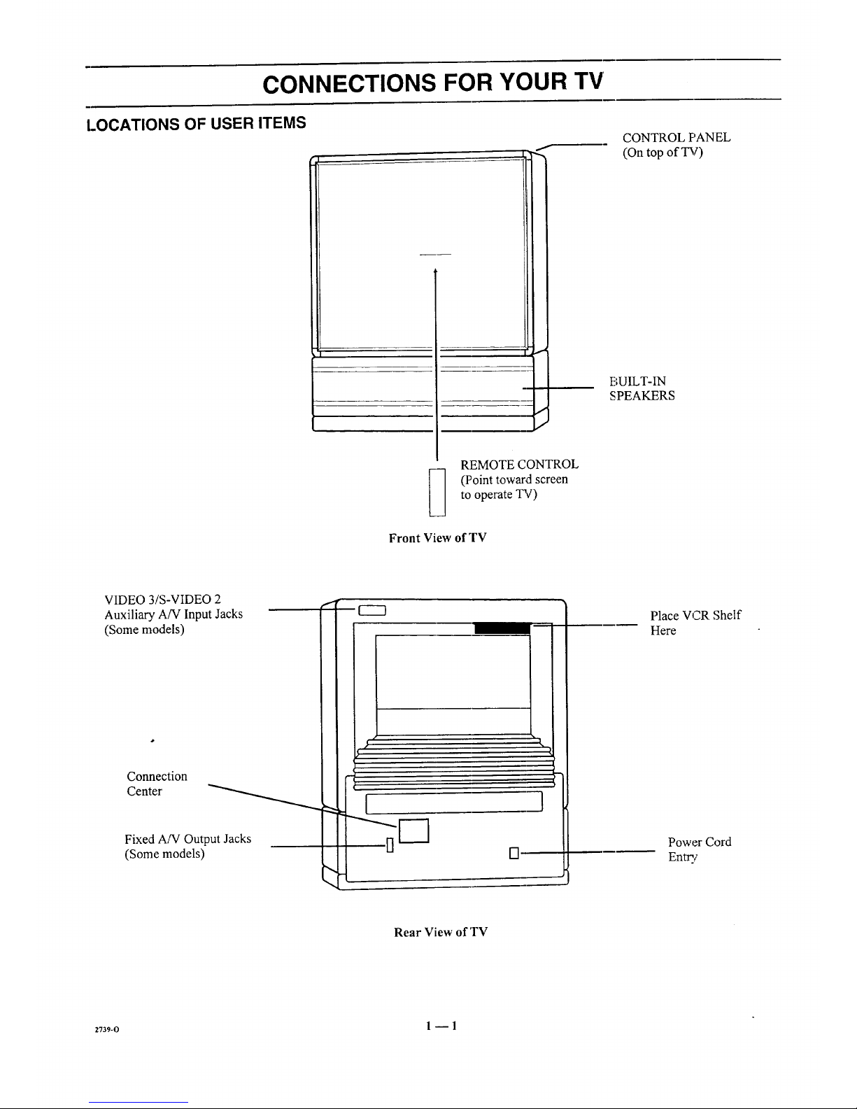
LOCATIONS OF USER ITEMS
L--.
I
f
I
I
CONTROL F'ANEL
(On top of TV)
BUILT-IN
SPEAKERS
REMOTE CONTROL
(Point toward screen
to operate TV)
Front View of TV
VIDEO 3/S-VIDEO 2
Auxiliary A/V Input Jacks
(Some models)
Connection
Center _
Fixed A/V Output Jacks
(Some models)
#
,1
i
I }
Place VCR Shelf
Here
Power Cord
Entry
Rear View of 'rv
2739_0 1 --1
Page 6

CONNECTIONS FOR YOUR TV
CONNECTION CENTER ON BACK OF TV
ANT/CABLE 1 or ANT/CABLE 2
75-ohm antenna-type connections to your
TV. Attach your antenna, cable-TV line or
VCR to either of these jacks.
LOOP OUT TO
DECODER
Use this output to route the
cable-TV signal back to the
decoder supplied by your
cable-TV system.
I
VIDEO 1 IN or
VIDEO 2 IN ]
Baseband audio and video "--"1
input from a VCR or |
other A!V component.
VIDEO 1 LOOP OUT
Use these jacks to send the
incoming audio and video signals
(from VIDEO 1 IN) to another A!V
component, such as a second VCR.
EXTERNAL AMP
Standard ph ono jack connectors for output to
the customer's audio amplifier.
RIGHT LEFT
TO EXTERNAL AMP
VARL_LE
AUDIO
OUTPUT
LOOPDUT ANT/CABLE2 ANT]CABLE1
TODECODER
VIDEO1 IN
VIDEO _--AUDIO_
VIDEO2IN
VIDEO r- AUDIO-_
R L
S-VIDEOI IN
LOOPOUT S-VIOEO R L SURROUNDSPKRS
I !
SURROUND
SPEAKER
Terminal connectors for
outpul; to optional
surround sound speakers.
S-VIDEO 1 IN
Audio and video input
from a Super-VHS VCR.
Some connections require additional cables or equipment which are not supplied with the TV.
OTHER A/V JACKS ON TV (Some Models)
S-VIDEO 2 IN
Audio and video input from a Super-VHS VCR.
LEF'A00,OI IV,0EO
VIDEO 3 IN
Baseband audio and video input from a camcorder or other
A/V component.
MONITOR OUT
VIDEO
AUDIO
RIGHT @--_
MONITOR OUT
Fixed-level baseband audio and video output to a
monitor or other A!V component. Program currently
being watched on your TV !s provided at t]hesejacks.
2739-o 1 --2
Page 7

CONNECTIONS FOR YOUR TV
STEP 1. MAKE BASIC CONNECTION TO TV
Select the hook up that best fits your needs. See the following
diagrams.
NOTE: The antenna may be connected to the ANT/CABLE 2
jack, however, connecting to the ANT/CABLE 1jack may
produce a better picture in weak signal areas.
Antenna
....... I:::N_
Flat Wire
300 ohm
OR
i
i
i
i
i
300175 ohm
Adaptor
Round Wire
75 ohm
Antenna
VCR
171 ANTENNA
I _') oo.rl
,r_._L-_,_0_----.
"_Channel 3/4
--------__ m_ ._ r_ ._
...... _o_
LOOPOUT ANT/_ABLE2 ANT/CAIILE1 _)
TO DECODER
VIDEO 1 IN [ VIDEO 2 IN
-d---_-_ L-_ .v,oEo,,. ,,
Cable-TV
(Direct Connection
toTV)
LOOPOUT ANT/CABLE2 ANT/CABLE 1
TODECODER
VIDEO 1 IN _ _ND ,
VIDEO r-AUDIO_
_____ R L
S-VIOEO 1 IN
\_z/
LOOPOUT
(_ (_ VARIABLE
AUDIO
OUTPUT
RKII,_ t.EFT
TO EXTERNALAMP
!o i!!i_!!!®
S VIOEO R L SURROUND SPKRS
Cable-TV
(Direct Connection VCR
Through VCR to TV) I
| A.NTENNAI
_ Vid en_ne I3/4
_
(_- @) ,,,_ ,,.
V,DEO --*UOlO_ ViDeO ,--,_UDZO--_LJl'_"i_l
--_--- _- ,-V,DEO.II_
LODPOLI) J S VIDEO R L SURRQUHO EPKRS
(eontirmed on next page)
z73_-o 1 --3
Page 8

CONNECTIONS FOR YOUR TV
STEP 1. MAKE BASIC CONNECTION TO TV
DECODER/
CONVERTER
Video
I m I Channel 314
_e_T OUT
v
I Direct I
_j VARIABLE
AUDIO
OUTPUT
RIGRI LEFT
TO EXTERNALAMP
o illli]'i@LOOP OUT ANT/CABLE 2 ANT/CABLE 1
TO DECODER
VIDEO 1 IN i VIOEO 2 IN
i ., ul _____ ,< it'÷
_--_ /_S-VOEO1 N
0 'hi+
LOOPOUT i S-VIDEO R SURROUND SPKIJS
DECODER/
CONVERTER ,.. VCR
, i--..,11_]h%en%e'314 [ ANTE[NNA"'_
LOOP OUT ANT/CABLE 2 ANT/CABLE I
TO DECODER
VIDEO 1 IN VIDEO 2 IN
VIDEO ¢- AIJDIQ _ J VIDEO r AUDIO_
LOOPOUT
o tlIIH i +
O L SURROUNO SPKRS
STEP 2. MAKE VCR CONNECTIONS TO TV
If you have a stereo VCR, you must make the A!V
connections shown in order to hear stereo sound while playing
a tape.
LOOPOUT S-VIDEO R L SURROUND SPKRS
STEREO VCR
OUTPUTS
-- G
[ #IDEO AUDIC L
Connections for second
stereo VCR or alternate
connections for first VCR.
2739-0 I --4
Page 9
CONNECTIONS FOR YOUR TV
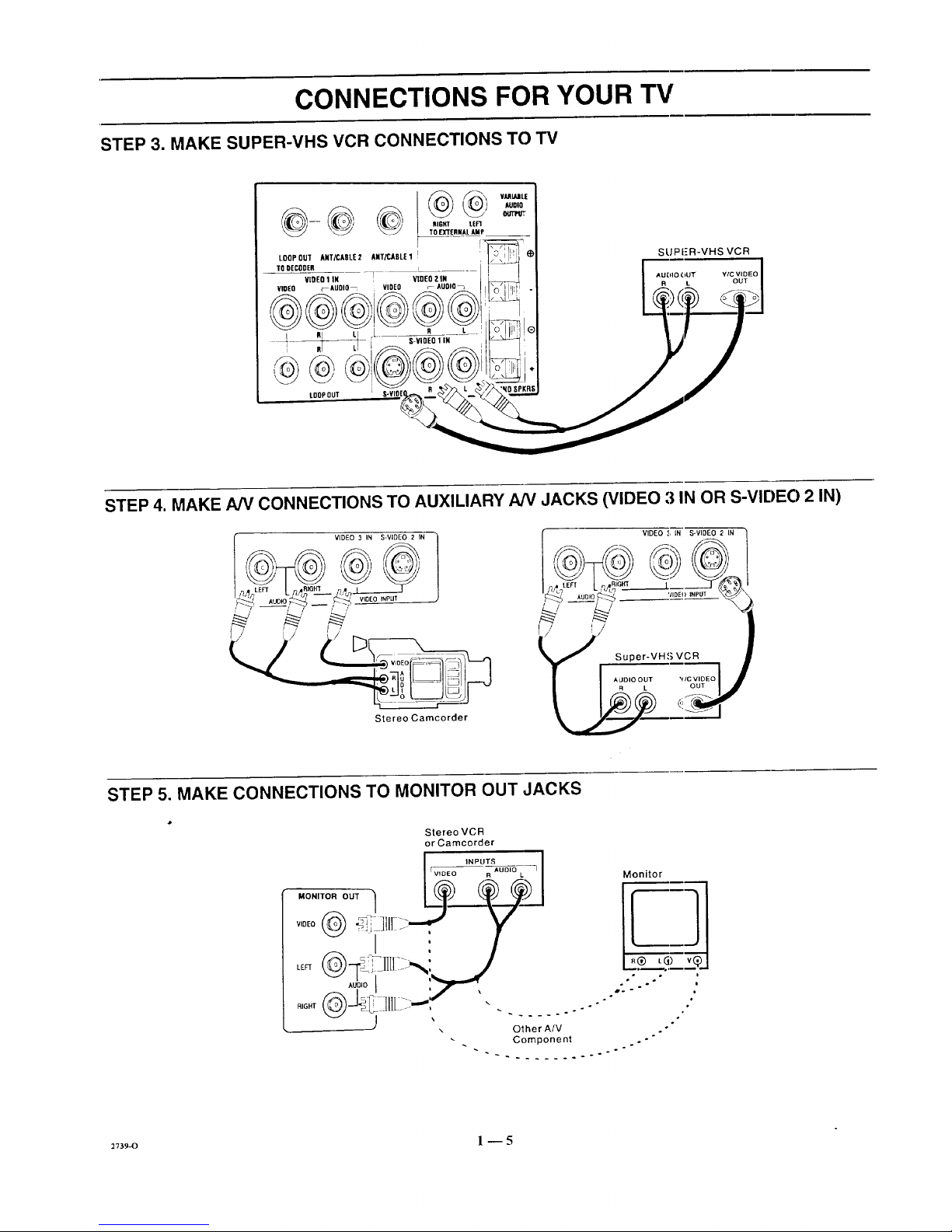
STEP 3. MAKE SUPER-VHS VCR CONNECTIONS TO "IV
@,t
RIGHT tEF1
TOE"XTERMAL AMP
LOOPOUT ANT/CADLE2 ANT!£,ADLE 1 l
TO DECODER
VIDEO 1 IN : VIDEO 2 IN
VIDEO f_AUDIO_ VIDEO r AUDIQ_
*i _'----_ [ S-ViDEO 1IN
I It L_ _
LDOPOUT [ S-VIOEQ,_ R
VILRIARLE
AUDIO
SUPFR-VHS VCR
STEP 4. MAKE A/V CONNECTIONS TO AUXILIARY NV JACKS (VIDEO ;i IN OR S-VIE)EO 2 IN)
VIDEO 3 IN S-VIDEO 2 IN
Stereo Camcorder
VIDEO :', LN S-VIDEO 2 IN
l Super-VH,S VCR •
STEP 5. MAKE CONNECTIONS TO MONITOR OUT JACKS
MONITOR OUT 1
LEFT
AUDIO {
J
Stereo VCR
or Camcorder
INPUTS
[ VIDE_
Monitor
.® L_) vQ
o
o i
i
2_s9-o l --5
Page 10

CONNECTIONS FOR YOUR TV
STEP 6. MAKE SURROUND SOUND CONNECTIONS TO TV
1. Mount and connect the optional surround sound
speakers by following the instructions provided with
the speakers.
2. Use the SURROUND option in the AUDIO Menu to
adjust the volume of the surround speakers.
3.
The level of the surround sound varies relative to the
difference between the left- and right-channel stereo
signals.
............ ,-=,
-- RIGHT LEE]"
TOB{TERNAL AMP
LOQPOUT ANT/CABLE2 ANT/CABLE1 I IIiOi'r _FI','l _1_.
,ODECODE,__ __ ]Vf--_-_i_l
video1., VIOEOZ.. ilL___]i I
VIDEO [--AUD|O_ VIDEO FAUDIO_ j tI",C"] ,,_ I -I
I
R L F R L (_
LOOPOUT ' S-YIOEO R L SURROUNDSPKRSJ
NOTE: MAKE SURE TV IS OFF
WHILE" CONNECTING SPEAKERS .
Surround
Speaker
(8 ohrn)
S
I"
Surround
Speaker
(8 ohm)
STEP 7. MAKE AUDIO CONNECTION TO STEREO AMPLIFIER
To takefull advantageof the Dolby Pro Logic audio system,
connect your stereo amplifier as shown in the illustration and
refer to the section entitled "AUDIO MENU."
LOOPOUT ANT/CABLE2 ANT/CABLE1
TODECODER
NOTE: MAKE SURE "IV IS OFF
WHILE CC)NNECTINGEXTERNAL AMP.
Bac_: of Customer's
Stereo/kmplifier
.P_,T r
_R SPKR OUTPUT
_ ,a_ T T
VIDEO 1 IN VIDEO 2 IN
VIDEO FAUDIO_ VIDEO _AUDIO_ _
i R L I R L _ o IIII1[ ®
S-V DEO 1 N _
nl LI
LOOPOUT S-_OEO R L SURAOUNDSPKRS
,i i,
To External
Speakers
2739-0 1 -- 6
Page 11

THE FIRST TIME YOU OPERATE YOUR TV
STEP 1. CONNECT THE POWER
A. Plug your TV into an unswitched AC power source.
B. Turn the TV ON by pressing OFF-ON.
[),3 not plug TV imo switched outlet
on cable-TV decoder or VCR
STEP 2. SELECT YOUR VIEWING SOURCE
A TV source refers to the equipment connected to the TV that
supplies the picture and sound to your TV. You select the
viewing source by using the SOURCE MENU.
NOTE: The antenna or cable must be connected to the TV
before using AUTO PROGRAM to find available channels.
To Access SOURCE MENU
1. Press SOURCE on the remote control to view the
SOURCE MENU.
2. Press SOURCE repeatedly until the desired source is
highlighted.
3. Press ENTER to return to normal viewing.
50URFE
* Some models only.
ANT/CABLE 1
ANT/CABLE 2
VIDEO 1
VIDEO 2
S-VIDEO 1
VIDEO 3
S-VIDEO 2
STEP 3. USE AUTO PROGRAM
AUTO PROGRAM finds all available channels and stores
them in the memory of the TV for use by CHANNEL (CH)
Up/Down. Use AUTO PROGRAM only when you first
install your TV, or when you permanently change the
connections to the TV. For example, when you replace the
antenna with a cable-TV system.
NOTE: AUTO PROGRAM can only be used with ANT/
CABLE 1 or 2 Source selection.
To Use AUTO PROGRAM
1. Press MENU on your remote control repeatedly until
the SETUP MENU appears.
2. Press SELECT (SEL) UP/DOWN to highlight Auto
Program.
3. Press ADJUST (ADJ) Left/Right to start Auto Program.
4. Use AUTO PROGRAM independently for each AN-
TENNA or CABLE signal source connected to your
TV. Select one source by using the SOURCE MENU
SETUP
] [A__JTOPROGRAM-]
!
CH. ADD/DEL
CH. LABELS
TUNING BANE)
AJTO TUNING
SOURCE ID
CLOCK SET
CAPTIONS
PROJO SETUP
Setup Menu with Aut,o Program Highlighted
(ANT/CABLE 1 or 2) and use AUTO PROGRAM.
When completed, select the other source and use
AUTO PROGRAM again.
When Some Channels Are Not Found
AUTO PROGRAM finds only active channels and stores
them in the favorite channel memory. You can add channels to
those stored in memory by using CH. ADD/DEE
STEP 4. TIME FUNCTIONS
Set Clock In TV
1. Press Menu until the SETUP MENU is selected.
2. Press SELECT (SEL) to highlight CLOCK SET then
use the number buttons on the remote to enter the
correct time.
3. Select AM or PM using the TIMER key on the remote.
4. Press ENTER (ENT) to start the clock.
AUTO PROGRAM
CH.ADDIDEL
CH.LABELS
TUNINGBAND
AUTOTUNING
SOURCEID
CLOCKSET
CAPTIONS
PROJOSETUP
] [ I0:00AM
Selecting Clock Set
(continued on next page)
273_-B 2_1
Page 12

THE FIRST TIME YOU OPERATE YOUR TV
To Use Sleep Timer
1. Press TIMER to view the SLEEP TIMER screen.
2. Press TIMER repeatedly until you reach desired shut-
off time.
One minute before the TV shuts off, the GOOD NIGHT
display appears on the screen. At this time you have a choice
of the following three actions.
1. Do nothing. The TV will shut offin one minute. The
display will count off the remaining seconds.
2. Remove the GOOD NIGHT display by pressing ENTER.
The TV will still shut off in one minute,
3. Delay the shut off by pressing TIMER to select a new
shut-off time.
SLEEP TIMER -1
0:15
_ SLEEP TIMER ---]
GOOD NIGHT
0:58
To Cancel the SLEEP TIMER
You can cancel the SLEEP TIMER by setting the SLEEP
TIMER stataasto OFF.
NOTE: The SLEEP TIMER resets to OFF when you turn off
the TV.
To Use ON/OFF Timer
1. Press TIMER and then MENU on the remote to view
the ON/OFF TIMER screen.
2. Press SELECT (SEL) to highlight ON TIME. Use the
number keys on the remote to enter the time for the
TV to turn on. Press TIMER to choose AM or PM.
3. Press SELECT (SEL) to highlight OFF TIME. Use
the number keys on the remote to enter the time for
the TV to turn off. Press TIMER to choose AM or
PM.
4. Press SELECT (SEL) to highlight TIMER. Use AD-
JUST (ADJ) on the remote to turn TIMER ON or OFF.
NOTE: A time must be set in either the ON TIME
or OFF TIME before you can turn the TIMER ON.
5. Press ENTER (ENT) to return to normal viewing.
NOTE: The ON/OFF Timer can not be used until after the
television's clock is set.
-- DNIOFFTIMER _.
">" DN TIM[ 11;51 PM
OFF TIME 12:00 PM
TIMER ON
ON/OFF Timer
STEP _i. USE OTHER OPTIONS
You may wantto usethe following options:
• Program the channels accessed when using CHANNEL
Up/Down. Refer to CH. ADD/DEL option for details.
• Add labels (such as NBC and ABC) to the Channel/Time
display. Refer to CH. LABELS option for details.
2736-o 2 -- 2
Page 13

REMOTE CONTROL MODEL SC2400
OPERATION
MUTE
Used to turn off sound while the picture
remains. Press again to restore the sound.
VOLUME Up/Down
Used to adjust the volume level of the TV.
t
Point toward your TV.
OFF-ON
MUTE DISPLAY
©0
CHAN
VOL _ VOL
CHAN
OFF/ON
Used to turn TV ON or OFF.
DISPLAY
-- Used to see Channel/Time display for TV
having on-screen displays. Press again to
_ remove display.
CItANNEL Up/Down
Used to select a "IV channel by going up or
down throu;_ channels.
SC2400
INSTALLING BATTERIES
When the effective range of the remote becomes noticeably
shorter, replace the batteries with two (2) high quality, size
AAA, alkaline batteries.
Zenith is not responsible for damage caused by battery
leakage. •
[
REMOVE TWO SCREWS TO REPLACE BATTERIES
® J' ,(9
2736-0 3 -- 1
Page 14

REMOTE CONTROL MODEL MBR3430
OPERATION
The multi-brand remote supplied with your new Zenith TV
allows you to operate most models of infrared (IR)
remote-controlled TVs, VCRs and cable-TV converters, even
if they are all different brands.
Your multi-brand remote has already been programmed to
operate your Zenith TV, a Zeaith VCR and a Zenith cable-TV
decoder. IImust be "taught" to operate other brands. Refer
tc, "Programming Your Remote Control" for derails.
CHOOSE THE OPERATING MODE
To operate >,ourTV, VCR or CABLE-TV decoder, you must
first choose the remote's mode of operation. To select the
mode, press the MODE key until the desired indicator lights.
Some KEYS on the remote, uill always operate a particular
appliance. For example, VOLUME always operates the TV
volume and PLAY always operates the VCR. The function of
mher keys depends on the mode selected.
Point toward unit
to be controlled
Operating mode selection
and indicators
Menu operations on TV
and some VCRs
Numbered buttons for
channel selection and other
uses
Learnfunctions for user
programmed sequences
NOTE: See following pages
for operating instructions.
I
A0_[_ A0_ r-fill CZ=
r_ i fgl _1 So0R_
+
®®®IN
SWAP TIllER SEQ
RECORD STOP PAUSE SEARCit
REW PLAY F FWO TV/VCf_
MBR3430
m
t-
t-
Controlled device
OFF/ON
Special features on 'TV and
some VCRs
Channel Up/Down
tbr TVs, VCRs and cable
Volume Up/Down for TV
Special features on some
'FVs and some VC1;Ls
2736-0 4-- 1
Page 15

REMOTE CONTROL MODEL MBR3430
TV OPERATIONS
The following functions and operations apply to your Zenith
TV. The remote control must be in the TV mode to operate
your TV.
MODE
Used to select the TV mode of
operation.
TV
Lights when TV mode of
operation is selected.
CC (Closed Captions)
Used to view closed captions
broadcast with some television
programs.
MENU, SELECT and ADJUST
Used with on-screen menus to
see menu, select an option, and
adjust that option.
Numbered Buttons
Used to select a TV channel.
ENTER
Used to view the Channel!Time
Display or to remove any on-
screen menu or display.
LEARN
Used to program remote.
PIP
Used to activate
Picture-In-Picture inset.
SWAP
Used to swap picturein PIP inset
with the main television picture.
t
Point toward your TV.
SELECT
® ® ®
®® ®
®® ®
PIP
TIMEI
STOP PAUSE
REW PLAY F FWD TVNC
OFF/ON
Llsed to turn TV ON or OFF.
€
SOURCE
Used to display the menu of TV
sources for some "IN's. Press again
to step through (he source
selections. On some TVs, press to
select AUX (Auxiliary) channel.
FLASHBK (Flashback)
Used to return to the last TV
channel you were watching.
CHANNEL Up/Down
. klsed to sequence throughthe TV
channels.
VOLUME Up/Down
Used toadjust the.TV's volume.
MUTE
Used to turn off sound while the
_. picture remains. Press again to
restore the sound.
SPATIAL EQUALIZATION
(SEq)
Used to select SEQ audio mode on
TVs equipped with SEQ feature.
FREEZE
Used to freeze the mc,tionof the
_ cture on the PIP inset.
TIMER
Used to activate the SLEEP
TIMER. Press repeatedly to select
desired turn-off _Iime.
2736-o 4 -- 2
Page 16

REMOTE CONTROL MODEL MBR3430
VCR OPERATIONS
The following functions and operations apply to Zenith VCR
models built after 1988. The remote control must be in the
VCR mode to operate your VCR.
The remote control supplied: with your VCR may have keys
not duplicated on the new remote. If these functions are
desired, the original remote control will have to be used.
MODE
Used to select the VCR mode of
operation.
VCR
Lights when VCR mode of
operation is selected.
MENU, SELECT, ADJUST
and QUIT
Used with on-screen menus and
programming options of the VCR.
See VCR operating guide for details.
Numbered Buttons
Used to select a TV channel through
the VCR. Also, used to set the
timer in the VCR, and to enter
programming information.
ENTER
Used with the numbered buttons to
select a TV channel through the VCR.
AM/PM °
Used to settimer during
programming.
t
Point toward your VCR.
® ®®
®®®
®®®
LEARN PIP FREEZE
SWAP TIMER SEQ
aD
RECORD STOP PAUSE SEARCH
REW PLAY F FWD
TVNCR
,OFF/ON
Used to turn VCR ON or OFF.
FI_,ASHBK (Flashback)
Used during VCR playback to
view the channel tuned by the
VCR.
_.. CIIANNEL Up/Down
Used to sequence through channels
on the VCR.
TIMER
Activates TIME RECORD on
some VCRs. See the VCR
operating guide fi_r de,tails.
TV/VCR
Used to select the source of the
programs seen on the TV. Switches
the VCR between TV mode and
VCR mode.
TV Mode: Chamlels are selected
ttuough the TV.
VCR Mode: Channels or tape
operation are selected through the
VCR.
RECORD, STOP, PAUSE,
SEARCH, RE'_€ r, PLAY and
F FWD
Used for tape recording and
playback functions. See the VCR
operating guide fix details.
2736-o 4 -- 3
Page 17

• REMOTE CONTROL MODEL MBR3430
CABLE-TV OPERATIONS
The following functions and operations apply to a Zenith
cable-TV decoder. The remote control must be in the CABLE
mode to operate your cable-TV decoder.
The remote control supplied with your cable-TV decoder may
have keys not duplicated on the new remote. If these functions
are desired, the original remote control will have to be used.
MODE
Used to select the Cable mode of
operation.
CABLE
Lights when CABLE mode of
operation is selected.
MENU, SELECT, ADJUST
and QUIT
Functions depend on Cable-TV
system. See Cable-TV decoder
operating guide for details.
Numbered Buttons
Used to select channels through
Cable-TV decoder.
ENTER
Used with the numbered buttons to
select a TV channel throu_ the
Cable-TV decoder.
Point toward your Cable-TV decoder.
J
ADJ _ ADJ
SELECT
MENU
@
QUIT
© ®®
® ®@
®®®
_ ENTER )
LEARN PIP FREEZE
OFF-ON
v
SOURCE
0
FLASHBK
IAI
CHANNEL
IVl
IAI
VOLUME
I11'1
MUTE
SWAP TIMER SEQ
aD _ _
RECORD STOP PAUSE SEARCH
(_B) aE) (IE_ c:=)
REW PLAY F FWD TVWCR
----F.
OFF/ON
Llsed to tum VCR ON or OFF.
SOURCE
" Selects "A" or "B" cable channels.
CHANNEL Up/Down
"Used to sequence,, through channels
on the Cable-TV decoder.
zvs6-o 4--4
Page 18

REMOTE CONTROL MODEL MBR3,430
PREPARATION FOR USE
Batteries are provided with this remote, but you must install
them before using the remote.
INSTALLING BATTERIES
When the effective operating range of your remote becomes
noticeably shorter, replace the batteries with two high-quality,
alkaline, size AAA batteries.
Zenith is not responsible for damage caused by battery
leakage.
After installing new batteries, lhe remote conlrol will set itself
to Zenith brand codes, as follows: TV=101, VCR=201 and
CABLE=301
If you are going to operate equipment that uses different
codes, the remote must be reprogranuned for those codes.
Step 1. Step 2. Step 3.
273_-o 4 -- 5
Page 19

REMOTE CONTROL MODEL MBR3430
PROGRAMMING BRAND CODES
Introduction
Before using your new remote control, it must be programmed
to recognize the brands of equipment it will be used to
operate. If you are using a Zenith VHS VCR or a Zenith
cable-TV decoder, the remote has already been programmed
for you.
Find the code that corresponds to each brand and type of
equipment you are going to operate. Refer to Tables 1, 2 and 3.
For example, if you were programming the remote for use
with a Zenith TV, you would look for "Zenith" in "Table 1",
and fred code "101."
Write the brand codes for your equipment on the following
lines.
TV COl)E:
CABLE CODE:
VCR CODE:
1. Press MODE repeatedly to select the ,desired TV,
VCR or CABLE operating mode for _Lheremote.
2. Press LEARN for about 5 seconds until the MODE
indicator lights for the :;elected TV, VCR or CABLE
mode of operation.
3. Enter the proper brand code number for the equipment
to be controlled.
4. Press LEARN. All three mode indicators should light
briefly, then turn off to indicate the brand code has
been programmed.
5. If all three mode indicators fail to lighl: briefly, an
error has occurred. Repeat Steps 1-4 to try again.
6. Repeat steps 1-4 to program the remote for the other
equipment you are using.
NOTE: CABLE mode can be programmed to operate a
second TV or second VCR, if desired.
When batteries are removed: It will be necessary to reprogram
the proper VCR and cable-TV decoder codes.
Operating Mode
Indicators
Numbered Buttons
Use to enter code number
for desired brand.
LEARN Button
I
ADJ ADJ M_
oo,
SELE(_T
®®®
®®®
®®®
_::D (::_ (::::)
LEARN PIP FREEZE
SOURCE
O
FLASHBK
CHANNEL
VOLUME
C2_
MUTE
SWAP TIMER SEQ
(:Z_ C3D C3D C::_
RECORD STOP PAUSE SEARCH
REW PLAY F FWD TVNCR
Operating MODE Selector
27364_1 4--6
Page 20

REMOTE CONTROL MODEL MBR3430
TV, VCR AND CABLE-TV OPERATING CODES
Table 1. TV Codes by Brand
TV Brand TV Brand
Name Code Name Code
Admiral 116 Montgomery Ward 119
Admiral 121 Montgomery Ward 121
Akai 104 Montgomery Ward 130
Amark 103 NEC 104
AOC 104 NEC 119
Bell & Howell 121 Panasonic 106
Centurion 119 Panasonic 107
Coronado 103 Philco 103
Curtis Mathes 116 Phitco 104
Curtis Mathes 119 Philco 112
Curtis Mathes 121 Philco 113
Daytron 119 Philips 112
Emerson 103 Philips 113
Emerson 104 Pioneer 135
Emerson 123 Portland 103
Emerson 124 Quasar 106
Emerson 131 Quasar 107
Emerson 136 Realistic 105
Fisher 109 Realistic 123
Fisher 118 Realistic 124
General Electric t06 RCA 104
General Electric I07 RCA 116
General Electric 114 RCA 126
General Electric 116 Sampo 119
Goldstar 103 Samsung 103
Goldstar 104 Samsung 119
Gotdstar 119 Samsung 134
Hitachi 102 Sanyo 108
Hitachi 103 Sanyo 109
Hitachi 129 Sanyo 118
JVC 125 Scott 119
JVC 132 Sears 103
J.C. Penney 104 Sears 108
J.C. Penney I10 Sears 109
J.C. Penney t14 Sears 110
J.C. Penney 117 Sears 111
J.C. Penney 119 Sears 118
KMC 103 Sears 134
KTV 103 Sharp 103
KTV 104 Sharp 105
Lodgenet 121 Sharp 122
Logik 121 Sharp 133
LXI 133 Sharp 137
LXI 137 Sony 115
Magnavox ,, 103 Sylvania 112
Magnavox 112 Sylvania 113
Magnavox 113 Sylvania 117
Magnavox 119 Sylvania 119
Magnavox 127 Sylvania 127
Magnavox 128 Sylvania 128
Majestic 121 Tatung 106
Marantz 104 Teknika 103
Marantz I20 Teknika 112
Memorex 121 Teknika 121
MGA/Mitsubishi 104 Teknika 124
MGA!Mitsubishi 119 Telerent 103
MGA/Mitsubishi 120 Telerent 121
MGA/Mitsubishi 130 Toshiba 110
Montgomery Ward 103 Toshiba 111
Montgomery Ward 104 Toshiba 134
Montgomery Ward 105 Yorx 119
Montgomery Ward 113 Zenith 101
Montgomery Ward 114
Table 2. VCR Codes by Brand
VCR Brand
Name
Akai
Audio Dynamics
Audio Dynamics
Broksonic
Canon
Citizen
Craig
VCR Brand
Code Name Code
223 Penlax 215
202 Philco 214
2!8 Philips 214
221 Philips 227
2!4 PiorLeer 2!0
209 PiorLeer 215
212 Pioneer Laser Disk 228
Curtis Mathes
Curtis Mathes
DBX
DBX
Emerson
Emerson
Emerson
Emerson
Emerson
Emerson
Fisher
Fisher
Fisher
Funai
General Electric
General Electric
General Electric
Goldstar
Hitachi
Instant Replay
Instant Replay
JVC
JVC
J.C. Penney
J.C. Penney
J.C. Penney
Kenwood
Magnavox
Magnavox
Marantz
Marantz
Marta
Memorex
Memorex
Memorex
MGA/Mitsubishi
MGA/Mitsubishi
214 Quasar 214
216 RCA 215
202 RCA 216
218 RCA 220
203 RCA 227
221 Realistic 206
223 Realistic 208
226 Rea?istic 212
233 Rea istic 214
235 Rea istic 231
211 Samsung 220
212 Samsung 230
213 Sanyo 206
231 Sanyo 212
214 Scolt 204
216 Scou 205
220 Scolt 233
209 Seazs 206
215 Sea_s 209
214 Seazs 211
227 Seaas 212
202 Seazs 215
225 Sharp 208
214 Sonic VHS 232
218 Sonic Video 8 217
227 Sylvania 207
202 Sylvania 214
207 Sylvania 227
214 Symphonic 231
207 Tashiko 209
218 Tatung 202
209 Teac 202
212 Teac 231
214 Teknika 234
231 Toshiba 205
204 Toshiba 215
222 Vector Research 204
218
202
218
201
225
229
Montgomery Ward 208 Vector Research
Montgomery Ward 214 Yamaha
Montgomery Ward 219 Yanlaha
NEC 202 Zenith VHS
NEC 218 Zenith VHS
Panasonic 2!4 Zenith VHS
Table 3. Cable Decoder Codes by
Brand
Cable Decoder Cable Decoder
Brandl Name Code Brand Name Code
Drake Sa_ellite 312 Pioneer 315
Drake Sa_:ellite 330 Regency 329
Gemirti 305 Samsung 335
Gemirti 331 Scientific Atlanta 316
General hstrttment 305 Scientific Atlanta 323
General Iastrument 306 Scientific Atlanta 336
Hamlia 302 Sprucer
Hamlin 303 (Panasonic) 313
Jerrold 304 Standard
Jerrold 307 Components 335
Jerrold 308 STS Satellite 324
Jerrold 309 Telecaption 4000 325
Jerrold 310 Tocom 317
Kale Vision 335 Tocom VIP 318
Macom 314 "['oshiba 322
Macorn 321 Toshiba Satellite 319
Macom Satellite 322 Zenith 301
Magnavo_ 334 Zenith 322
NSC 335 Zenith AV3000 327
Oak 311 Zenith Satellite 312
Oak 332 Zenith Satellite 330
Panasnnic 313 Zenith Satellite 328
Panasnnic 320 Zenith Laser Disk 326
Paragon (Zenith) 333
2736-0 4 -- 7
Page 21

QUICK REFERENCE TO ON-SCREEN MENUS
AVAILABLE MENUS
Your TV is icon and menu operated. That is, an icon is
selected at the top of the TV screen and a menu of adjustment
options appears.
[SETU P
IAUTO PROGRAM
CH. ADD/DEL
CH. LABELS
TUNING BAND
AUTO TUNING
SOURCE ID
CLOCK SET
CAPTIONS
PROJO SETUP
\
RUOIO
UIOEO
\
Unhighlighted
PIP
Highlighted
Menu for highlighted icon appears
at left of TV screen.
SUMMARY OF MENU ITEMS
SOUl:lEE
[ANT/CABLE 1
ANT/CABLE 2
VIDEO 1
VIDEO 2
S-VIDEO 1
VIDEO 3 *
S-VIDEO 2 *
* Some models only.
ANT/CABLE 1or 2 : Either of these sources may be used
for input from an antenna or acable-TV line.
VIDEO 1 or 2 : Either of these sources may be used for input
from a VCR.
S-VIDEO 1 : Use this source ira Super-VHS VCR is
connected to your TV.
VIDEO 3 : Use this source if acamcorder i+,;connected to
your TV.
S-VIDEO 2 : Use this sou:rc_:ifa second Super-VHS VCR is
connected to your TV.
IAUTO PROGRAM
CH. ADD/DEL
CH. LABELS
TUNING BAND
AUTO TUNING
SOURCE ID
CLOCK SET
CAPTIONS
PROJO SETUP
AUTO PROGRAM: Finds all available channels and stores
them in the memory of the TV for use with CHANNEL
Up/Down.
CH. ADD/DEL: Changes the list of active Channels stored in
memory so that only your favorite channels are selected when
using CHANNEL Up/Down.
CH. LABELS: Adds a channel label or name to the
channel/time display. For example, ABC may appear when
th:tsnetwork channel is tuned.
TUNING BAND: Determines the operation of the channel
selector inside the TV.
AUTO TUNING: Lets your TV compensate for variations in
broadcast and cable-TV frequencies.
SOURCE ID: Lets you assign a relevant name to each input
source.
CLOCK SET: Sets the TV'.,; internal clock
CAPTIONS: Displays closec captions (CC) or informational
text when available.
PROJO SFTUP: Adjusts 1he dynamic color convergence of
the TV picture.
273s-o 5 -- 1
Page 22

QUICK REFERENCE TO ON-SCREEN ldENUS
SUMMARY OF MENU ITEMS
\
AUDIO
[BASS
TREBLE
BALANCE
AUDIO
ENHANCEMENT
BASS: Adjusts the BASS (low-fi'equency) level.
TREBLE: Adjusts the TREBLE 0aigh-frequency) level.
BALANCE: Adjusts the BALANCE ofsotmd between the
speakers.
AUDIO MODE: Allows fer receiving a Second Audio
Program (SAP), such as a program broadcast witl't two audio
portions (typically two langaa_es), or lets you select
stereophonic (STEREO) or monaural (MONO) speaker
operation.
ENHANCEMENT: Provicles a list of options for enhancing
the audio.
UIDED
ICO NTRAST
BRIGHTNESS
COLOR
TINT
SHARPNESS
COLOR TEMP
VIDEO FILTER
AUTO FLESH
PICTURE PREF
CONTRAST: Adjusts the ow,'rall contrast and color level of
the picture.
BRIGHTNESS: Adjusts the brightness level of black areas in
the picture.
COLOR: Adjusts the intensity of the colors in the picture.
TINT: Adjusts the color of the flesh tones.
SHARPNESS: Adjusts the claJStyof the edges of objects for the
clearest possible picture.
COLOR TEMP: Changes the "color temperature" or picture
white balance between cooler natural whites and warmer (red)
cotors.
VIDEO FILTER: Reduces video "noise" or interference in
dark picture areas resulting in clearer overall pictures.
AUTO FLESH: Automatical]y maintains natural skin tones
under changing scene and vid_:o source condition:s.
PICTURE PREF: Lets you ciecide if you want 1o use your
own CUSTOM video settings, the factory PRESET video
settings, or the THEATER video settings for optimum
viewing in low-light conditions.
P
r.
PIP
* Some models only.
ICH. GUIDE
CH. REVIEW
PIP SOURCE
PIP COLOR
PIP TINT
PIP SIZE
CH. GUIDE: Provides a visual review ofal]Lchannels in the
channel scan memory for the ¢;urrently selected ANT/
CABLE source.
CIL REVIEW: Provides a visual review of the last three (3)
channels tuned on the TV.
PIP SOURCE: Lets you select the equipment that supplies
the picture to the PIP inset.
PIP COLOR: Adjusts the inlensity of the colors in the PIP
inset.
PIP TINT: ,Adjusts the color of the flesh tortes.
PIP SIZE: Lets you choose I:.etween seeing a larger or
smaller PIP inset.
273_o 5 _ 2
Page 23

MENUo
QUICK REFERENCE TO ON-SCREEN " "
MENU OPERATION EXAMPLE
Press MENU repeatedly until the desired icon is highlighted
and its menu is showing. This example shows choosing the
SETUP MENU.
MENU
5ETUPI
[AUTO PROGRAM
CH. ADD/DEL
CH. LABELS
TUNING BAND
AUTO TUNING
SOURCE ID
CLOCK SET
CAPTIONS
PROJO SETUP
Press SELECT (SEL) Up/Down repeatedly until the desired
option/feature is highlighted. This example shows choosing
TUNING BAND.
AUTOPROGP.Md
CH. ADD/DEL
CH. LABELS
TUNING BAND
AUTOTUNING
SOURCE ID
CLOCK SET
CAPTIONS
PROJO SETUP
] I CABLE-CAIV
Press ADJUST (ADJ) Left/Right to adjust the option. This
example shows the choices you have for TUNING BAND.
ADJ. ADJ.
Tuning Band options are:
_UTOPROGRAM
CH. ADD/DEL
CH. LABELS
T_UNINGBAND
AU_I
SOURCE ID
CLOCK SET
CAPTIONS
PROJO SETUP
] [ CABLE-CAiN
BROADCAST_
CABLE-CATV
CABLE-HRC
CABLE-ICC
Press ENTER (ENT) or wait a few seconds and the TV will
return automatically to normal operation.
z73_o 5 _ 3
Page 24

SOURCE MENU
50URI'E,
[ANT/CABLE 1
ANT/CABLE 2
VIDEO 1
VIDEO 2
S-VIDEO 1
VIDE() 3
S-VIDEO 2
Some models only
Source Menu
SOURCE SELECTION
Purpose
The viewing "source" refers to the equipment that supplies
the picture and sound to your TV. You select the viewing
source by using the SOURCE MENU.
To Access the SOURCE MENU
1. Press SOURCE on the remote control to view the
Menu icons with SOURCE already selected and its
menu showing.
2. Press SOURCE repeatedly until the source you want
is highlighted.
3. Press ENTER to return to normal viewing.
f
CH 2
10:56
-.___ J
ChannelFHme Display
['or Antenna or Cable
Source
VIDEO 1
10:56
J
ChanneFTime Display
For Video or S-Video
Source
SOURCE IDENTIFICATION
YELLOW
LEVI RIGHT
AUDIO INPUT
WHITE
VIDEO INPUT )
Auxiliary AN Jacks
Selecting VIDEO 3 : Routes the auxiliary video source (such
as a camcol;der or VCR) to the TV for viewing. The video
source must be connected to the corresponding VIDEO 3
jacks.
Selecting S-VIDEO 2: Routes the auxiliary Super-VHS VCR
source to the TV for viewing. The Super-VHS VCR must be
connected to the corresponding S-VIDEO 2 jacks.
I_GENTA
BLUE RED
_._ _ m(',aT ten
TOE_q'ER8AL AMP OR SPKR
SPEAKERS
INT: • EIT
LOflPOUT ANT/CARLF]2 ANT/CABLE1 _ @
TO DECODER
VIDEO1IN VIDEO2114
VIDEO I--AUIIIO 7 '_ VIDEO rAUDIO_ _]_
]
LT. BLUE GREEN
Connection Center on Back of TV
Selecting ANT/CABLE 1 or 2 : Routes the ANTENNA or
cable-TV source to the TV for viewing. You see program
material from whichever sigmd source is connected to the
ANT/CABLE 1 or 2 jack.
Selecting VIDEO 1 or 2 : Routes the video source (such as a
VCR or a Video Disc player) to the TV for viewing. The
video source must be connected to the corresponding VIDEO
l/2 jacks.
Selecting S-VIDEO 1 : Routes the auxiliary Super-VHS
VCR Source to the TV for viewing. The Super-VHS VCR
must be connected to the corresponding input jacks.
2v36-o 6 -- I
Page 25

SETUP MENU
To Access SETUP Menu
Refer to the "Using On-Screen
Menus" section for details.
Before Using SETUP Menu
Connect and turn ON all external
equipment, such as cable TV decoder,
VCR, etc. before using any item on
the SETUP Menu.
SETUP,
[AUTO PROGRAM
CH. ADD/DEL
CH. LABELS
TUNING BAND
AUTO TUNING
SOURCE ID
CLOCK SET
CAPTIONS
PROJO SETUP
Main Setup Menu
fSOLIRCE ID ]
CLOCK SET
CAPTIONS
PROJO SETUP
Setup Menu for Video
and S-Video Sources
AUTO PROGRAM
Purpose
Finds all available channels and stores them in the memory of
the TV for use by CHANNEL (CH) Up/Down.
Use AUTO PROGRAM only when you first install your TV,
or when you permanently change the connections to the TV.
For example, when you replace the antenna with a cable-TV
system.
NOTE: AUTO PROGRAM can only be used with ANT/
CABLE 1 or 2 Source selection.
To Use AUTO PROGRAM
1. Press ADJUST (ADJ) Left/Right to start Auto Pro-
gram.
.
Use AUTO PROGRAM independently for each AN-
TENNA or CABLE signal source connected to your
TV, Select one source by using the SOURCE MENU
(ANT/CABLE 1 or 2) and use AUTO PROGRAM.
When completed, select the other source and use
AUTO PROGRAM again.
A-UTOPROGRAM
CH. ADD/DEL
CH. LABELS
TUNING BAND
AUTO TUNING
SOURCE ID
CLOCK SET
CAPTIONS
PROJO SETUP
][ START
k ______
Selecting Auto Program
When Some Channels Are Not Found
OH. (Channel) ADD/DEL
Purpose
Lets you add channels to and remove channels from the
channel scan. In this way you can customize the channels that
are accessed through CHANNEL (CH) Up/Down.
NOTE:- CH. ADD/DEL can only be used with ANT/CABLE
1 or 2 Source selection.
To Add a Channel to Scan Sequence
1. Press ADJUST (ADJ) Left/Right to view the channel
add/delete screen.
2. Use the number buttons on the remote to enter the
channel or use ADJUST (ADJ) Left/Right and SE-
AUTO PROGRAM finds only active chanrtels and stores
them in the favorite channel memory. You ,'an add channels to
those stored in memory by using CH. ADD/DEL.
AUTO PROGRAM
CH. ADD/DEL
CH. LABELS
TUNING BAND
AUTO TUNING
SOURCE ID
CLOCK SET
CAPTIONS
PROJO SETUP
3.
LECT Up/Down to move the highlight to the channel
you wish to add.
Add the channel by pressing SOURCE until the dis-
play shows ADDED.
] [ CH 15ADD
Selecting Ch. Add/Del
'to Delete a Channel from Scan Sequence
1. Press ADJUST (ADJ) Left/Right to view the channel
add/delete screen.
:2. Use the number batlons on the remote to enter the
channel or use ADJUST (ADJ) Left/Right and SE-
LECT Up/Down to n:ove the highlight to the channel
you wish to delete.
Delete the channel by pressing SOURCE until the
,
display shows DELETED.
(continued on next page)
:_3s-o 7 -- l
Page 26

SETUP MENU
r
m
Available channels for currently
selected source.
Available channels are:
BROADCAST Band --
VHF2 to 13, UHF 14 to 69 --
CATV, HRC and ICC Bands --
1to 125
Use SELECT Down to move
highlight to higher numbers.
\
1
7
13
19
25
31
37
43
49
55
61
67
73
79
85
2 3 4 5 6
8 9 10 11 12
14 [] 16
17 18
20 21 22 23 24
26 27 28 29 30
32 33 34 35 36
38 39 40 41 42
44 45 46 47 48
50 51 52 53 54
56 57 58 59 60
62 63 64 65 66
68 69 70 71 72
74 75 76 77 78
8O 81 82 83 84
86 87 88 89 90
PRESS
SOURCE TO
CHANGE
ADDED
CH 15
J
Typical Channel Add/Delete Screen
__ Live view of currently
selected channel.
Instructions
Channel Status: Added to or
Deleted from cll_annelscan.
I Currently selected Channel.
CH. (Channel) LABELS
Purpose
Assigns a network label or "name" to the selected channels. If
you choose the label "ABC" for channel 15, "ABC" appears
in the Channel!Time display when channel 15 is selected for
viewing.
NOTE: CH. LABELS can only be used with ANT/
CABLE 1or 2 Source selection.
A&E
ABC
ACTS
ADC
AMC
BET
BRAV
CA
CBC
CBN
CBS
CMTV
CNBC FAM MMT SHOW
CNN FNN MTV SIN
COM FOX NBC TBS
CSPN GALA NICK TBN
CTN HBO NOS TELE
CTV I-IN PBS TLC
DIS HSE PLAY TMC
DISC HSN PTL TNN
E! IC QVC TNT
ENC INSP RDS TRAV
ESPN LIFE REQ TSN
El" MAX SC TVA
EWTN MEU SCFI TWN
List Of Available Channel Labels
USA
VC
VCR
VH1
VISN
VJN
WGN
WTBS
WWOR
YTV
To Use CH. LABELS
1. Press ADJUST (ADJ) Left/Right to view the channel
label screen.
2. Use ADJUST (ADJ) Left/Right and SELECT
Up/Down to move the iaighlight to the LABEL you
wish to assign to the current channel.
3. To label another channel, use CHANNEL Up/Down,
or the number keys on the remote cowLrol to select the
channel number and repeat step 2.
4. To remove an assigned channel label, select the four
dashes.
AUTO PROGRAM
CH. ADD/DEL
ICH.LABELS- ] r CH2ABC
TUNING BAND
AUTOTUNING
SOURCE ID
CLOCK SET
CAPTIONS
PROJOSETUP
Selecting Ch. Labels
Available channel
labels.
f
AMC
CBN
COM
DISC
EWIN
HBO
INSP
MTV
PLAY
SC
TBN
TNT
USA
_ VJN
ACTS ADCA&E
BET BRAV CA CBC
CBS CMTV CNBC CNN
CSPN CTN CTV DIS
E! ENC ESPN ET
FAM FNN FOX GALA
HN HSE HSN IC
LIFE MAX MEU MMT
NBC NICK NOS PBS
PTL QVC RDS REQ
SCFI SHOW SIN TBS
TELE TLC TMC TNN
TRAV TSN TVA TWN
VC VCR VH1 VlSN
WGN WTBS WWOR YTV
LABEL
FOR
CH 15
Typical Channel Label Screen
I,ive view of currently
selected channel.
Currently selected channel.
2738-0 7 -- 2
Page 27

SETUP MENU
TUNING BAND
Purpose
Allows for setting the TV channel selector (tuner) to match
your antenna or cable-TV system.
If you are having difficulty tuning channels, the TUNING
BAND may have to be set manually to match your viewing
needs.
kUTO PROGRAM
CH. ADD/DEL
CH. LABELS
TUNINGBAND
AUTO TUNING
SOURCE ID
CLOCK SET
CAPTIONS
PROJO SETUP
i [ CABLE-CATV
Selecting Tuning Band
NOTE: TUNING BAND can only be used with ANT/
CABLE 1 or 2 Source selection.
To Use TUNING BAND
Press ADJUST (ADJ) Le_Tdght to select the tuning band that
gives you the most charmels:
• BROADCAST-- isused for standard "ow._r-the-air'' broad-
casts.
• CABLE --. CATV is used for most standard cable-TV
(CATV) systems.
• CABLE -- HRC is usedfor cable-TV systems that use HRC
(Harmonically Related Carrier).
• CABLE -- ICC is used for cable-TV systems using ICC
(Incremental Coherent Carrier).
Available Channels per E;and
The chamlels that are available in the broadcast and cable
tuning bands are shown bellow:
BROADCAST Band --- VHF 2 to 13, UtIF 14 to 69
CATV, HRC and ICC Bands -- 1 to 125
AUTO TUNING
Purpose
Lets your TV compensate for variations in broadcast and
cable-TV frequencies.
AUTO PROGRAM
CH. ADD/DEL
CH. LABELS
TUNING BAND
_NiNG
SOURCE ID
CLOCK SET
CAPTIONS
PROJO SETUP
FIXED
Selecting Auto Tuning
If you are having difficult5' tuning channels, the AUTO
TUNING may have to be set manually to match your viewing
needs.
NOTE: AUTO TUNING can only be used with ANT/
CABLE I or 2 Source selection.
To Use AUTO TUNING
Press ADJUST (ADJ) LefdRight to selec:Lthe mode of
operation that gives you the most channels:
• FIXED is used to receive "over-the-air" TV stations, and
with many cable-TV systems.
• SEARCH is used only when the TV must search to find the
frequency being received, such as when used with certain
VCR=_and video game controllers.
SOURCE ID
Purpose
Assigns a descriptive "name" to the input sources. For
example, the VIDEO 1 source may be named VCR. "VCR"
now appears in the source menu as a reminder that your VCR
is comlected to VIDEO 1 input jacks.
To Use SOURCE ID
1. Press ADJUST (ADJ) Left/Right to view the
SOURCE ID screen.
2. Use SELECT Up/Down to select a SOURCE.
3. Use ADJUST (ADJ) Left!Right to select the desired
name for the source.
AUTO PROGRAM
CH. ADD/DEL
CH. LABELS
TUNING BAND
AUTO TUNING
SOURCE tD
CLOCK Ski
CAPTIONS
PROJO SEIUP
! ] LABEL
Selecting Source ID
(continued on next page)
2738-o 7--3
Page 28

SETUP MENU
VIDEO GAMES AND OTHER FIXED
PATTERN DISPLAY CAUTION
If you use your TV for video games or other fixed
displays, avoid setting the BRIGHTNESS control for
an excessively bright picture. A bright, fixed pattern.
if used for long periods of time, can result in a
permanent imprint on the TV picture tube. You can
reduce this possibility by alternating the use of the
fixed pattern display with normal TV picture
viewing, by turning down the CONTRAST control
for sustained fixed pattern use, and by turning off the
fixed pattern display when not in use.
#
Live view of currently
selected source.
SOURCE LABEL
ANT/CABLE 1 ANTENNA,
ANT/CABLE2 CABLE
q
V_I _ [VCR
VIDEO2
S-VIDEO 1 LASER DISK
]..j11
Jt
I
Typical Source ID Screen
Optional :names for
ANT7 CABLE 1 or 2
Sources are:
AN'rENNA, CABLE,
CABLE BOX,
SATELLITE.
Optional names for
VIDEO Sources are:
VCR, CAMCORDER,
LASER DISK,
VIDEO CAME.
(;;LOCK SET
Purpose
Sets the clock in the TV to the correct time.
To Use CLOCK SET from Remote Control
Use the numbered buttons on the remote control to enter the
current time. Press ENTER (ENT) to start the clock. Press
TIMER to select AM or PM.
CH13
10:56
STEREO
J
Channel/Time Display On TV Screen
(-_
i
AUTO PROGRAM
CR. ADD/DEL
CH. LABELS
TUNINGBAND
AUTOTUNING
SOURCE ID
(?,LOCKSET
!CAPTIONS
, PROJOSETUP
j [ 10:00AM
Selecting (',lock Set
To Use CLOCK SET from C,ontrol Panel
Use ADJUST (ADJ) Left/Right to set the time. Pres:_ ENTER
(ENT) to start the clock.
CAPTIONS
Purpose
Displays closed captions (CC) or informational text when
available on the selected channel.
To Use CAPTIONS
Press ADJUST (ADJ) Left/Right to select desired mode of
operation. Five different selections can be made: OFF,
CAPTION 1, CAPTION 2, TEXT 1 or TEXT 2.
\UTO PROGRAM
CH. ADD/DEL
CH. LABELS
TUNING BAND
AUTO TUNING
SOURCE ID
CLOCK SET
CAPTIONS
PROJO SETUP
] [ CAPTION1
Selecting Captions
At the time this instruction manual was written, little or no
information appeared for any sekxztion except CAPTION 1.
Therefore you should choose CAPTION 1 and leave it in that
selection unless you know there is something available in one
of the other options. Once you make a selection, that selection
is remembered until you change it.
Heltlt°h!eAr;ey°u i _.It_nignhtlT'7:OOPM°n)
Typical Captions Display
Caplions may be shown
anywhere on the screen.
Typical Text Display
Fixed size text window.
May be all black when no
information is shown.
2739-B 7 -- 4
Page 29

SETUP MENU
PROJO SETUP
Purpose
Lets you verify and adjust, if needed, the dynamic color
convergence of the TV picture.
Ifyott move your TV from its original location, or if after
time, yoti notice color "fringes" around objects in the picture,
you may want to realign the colors by adjusting the
convergence as described in the following steps.
g-
AUTO PROGRAM
CH. ADD/DEL
CH, LABELS
TUNING BAND
AUTO TUNING
SOURCE ID
CLOCK SET
CAPTIONS
PROJO SETUP
] [ TOCONVERGE
Selecting Projo Setup
To Use PROJO SETUP
1. Press ADJUST (ADJ) Left/Right to view the conver-
gence lines.
If the display appears as four intersecting lines, all
white in color, no adjustment is necessary.
If there are more than four lines, each a different
color, you must adjust the convergence.
2. Use SOURCE key to select the Red reference color.
3. Use the SELECT and ADJUST arrow keys (Up,
Down, Left and Right) to adjust the Red lines until
they are on top of the Green lines.
4. Use SOURCE key to select the Blue reference color.
5. Use the SELECT and ADJUST arrow keys (Up,
Down, Left and Right) to adjust the Blue lines until
they are on top of the other lines• All lines should
now be white.
_PRESS SOURCEKEYTO SELECTCOLOR
PRESSARROW KEYSTO CONVERGE
Correct Convergence
PRESSSOURCETO SELECTCOLOR
/PRESSARROW KEYS TOCONVERGE RED
:ORBLUE)
___m
Incorrect Convergence
2738-0 7 -- 5
Page 30

AUDIO MENU
\
RUOlO
[BASS
TREBLE
BALANCE
AUDIO
ENHANCEMENT
1
BASS
Adjusts the BASS (low-frequency) level. (Can not be adjusted while PRO LOGIC
ENHANCEMENT is selected.)
TREBLE Adjusts the TREBLE (high-frequency) level. (Can not: be adjusted while PRO LOGIC
ENHANCEMENT is selected.)
BALANCE Adjusts the balance of sound between the TV's speakers for MONO, SAP, PSEUDO STEREO and
STEREO AUDIO programs.
AUDIO
(AUDIO mode options are
not available while using a
VIDEO or S-VIDEO
source. The audio received
fi'om these sources are as-
sumed to be stereo .)
Allows you to select STEREO, MONO or 2ND AUDIO/SAP speaker operation.
STEREO: Directs the sound to the left and right speakers as supplied by the program
source (broadcast TV, VCR, etc.)
MONO:
Directs the same sound to both left and right speakers even if the source
being received is in stereo.
2ND AUDIO/SAP: Directs the sound for the Second Audio Progr_n to both the left and right
speakers. SAP sound is always monaural. If the :SAP signal ends, the audio
defaults to either stereo or mono depending on the audio being received.
ENHANCEMENT Provides a list of options for enhancing the TV's audio. The options shown depend on what is
selected for the AUDIO option above.
MONO or 2ND Your audio ENHANCEMENT options are OFF and PSEUDO STEREO.
AUDIO/SAP OFF specifies that no ENHANC.EMENT is activated. PSEUDO STEREO
Selected: enhances monaural audio to emulate stereo-like sound.
STEREO Selected:
Your audio ENHANCEMENT options are OFF, CONCERT !-DkLL,
THEATER, NIGHT CLUB, STADIUM, PHANTOM PRO LOGIC, and
PRO LOGIC. OFF specifies that no ENHANCEMENT is activated. For the
other options, see "STEREO Operation," " PttANTOM PRO I_,OGIC
Operation," and "PRO LOGIC Operation."
To Access Audio Menu
Refer to the "Quick Reference to On-Screen Menus" section
for details.
NOTE: All adjustments on the AUDIO MENU are optional.
You do not have to use these features in order to use your TV.
To Adjust Audio Menu Options
1. Press SELECT (SEL) Up/Down to select an option
from the menu.
2.
Press ADJUST (ADJ) Left/Right to adjust the option
for the most pleasing sound.
For some options, an additional adjustment screen
will appear at this point. Refer to the following opera-
tion descriptions.
MONO & SAP Operation
For the most basic MONO & SAP operation, select
ENHANCEMENT and choose OFF. Then, select BASS,
TREBLE and BALANCE and adjust for the most pleasing
sound
PSEUDO STEREO Operation
To add Pseudo Stereo sound to MONO & SAP eperation,
select ENHANCEMENT and choose PSEUDO STEREO.
Then, select BASS and TREBLE and adjust for the most
pleasing sound.
Next, select BALANCE and press ADJUST (ADJ) Left/Right
to view the Pseudo Stereo Balance screen. Press ADJUST
(ADJ) Left/Right to balance the: sound between tlhe le,ft and
right speakers and press SELECT (SEL) Up/Down to increase
or decrease Surround Sound volume.
(continued on next page)
2736-0 8 -- ]
Page 31

AUDIO MENU
STEREO Operation
To operate your TV in stereo mode, choose STEREO as the
AUDIO option. Then, select a desired ENHANCEMENT
(CONCERT HALL, THEATER, NIGHT CLUB or
STADIUM) or set ENHANCEMENT to OFF. Also, select
BASS and TREBLE and adjust for the most pleasing sound.
Next, select BALANCE and press ADJUST (ADJ) Left/Right
to view the Stereo Balance screen. Press ADJUST (ADJ)
Left/Right to balance the sound between the left and right
speakers and press SELECT (SEL) Up/Down to increase or
decrease Surround Sound volume.
PHANTOM PRO LOGIC Operation
To add Phantom PRO LOGIC sound to your stereo operation,
select PHANTOM PRO LOGIC as the ENHANCEMENT.
Then, select BASS and TREBLE and adjust for the most
pleasing sound.
Next, select BALANCE and press ADJUST (ADJ) Left!Right
to view the PRO LOGIC Balance Screen.
Press SOURCE to select a speaker (Left, Right or Surround).
A highlight box will toggle back-and-forth between the
selected speaker and the CENTER REFERENCE. An audible
"hissing" sound will also toggle with the box. Press ADJUST
(ADJ) Left/Right to set the volume of the "hissing" (for the
selected speaker) to approximately the same level as the
"hissing" of the CENTER REFERENCE. Do this for each
speaker.
PRO LOGIC Operation
To add "true" PRO LOGIC sound to your stereo operation,
select PRO LOGIC as the ENHANCEMENT. Then, select
BALANCE; and press ADJUST (ADJ) Left/Right to view the
PRO LOGIC Balance Screen.
Press SOURCE to select a speaker (Left, Right or Surround).
A highlight box will toggle back-and-forth between the
selected speaker and the CENTER REFERENCE. An audible
"hissing" sound will also toggle with the box. Press ADJUST
(ADJ) Let_q_ight to set the volume of the "hissing" (for the
selected speaker) to approximately the same level as the
"hissing" of the CENTER REFERENCE. Do this for each
speaker."
NOTES:
• Surround speakers must be connected to hear Surround
Sound. (See Step 6, Chapter 1.)
• An external amplifier must be connected to hear "true" PRO
LOGIC Sound. (See Step 7, Chapter i.)
° To appreciate the quality of sound provided by the Dolby
Pro Logic audio system, make sure the speakers are balanced
as described above.
• While PRO LOGIC is selected, BASS and TREBLE adjust-
ments are not possible. These must be adjusted using the
external amplifier.
FFIONT
SURROUND
',----I SLIRROUNDSF'EAKERSREQUIRED ] ._..-.)
\
Message appears when
adjusting Surround Sound.
Pseudo Stereo & Stereo Balance Adjust: Screen
PRESS SOURCE "1"OCHANGE SPEAKER
PRESS ADJUST 3O CHANGE LEVEl_
RIGHT
+
EXTERNAI_ A MPL[ F|ER R EQU[ [:lED ]_
\
Highlight boxtoggles
between selectedspeaker Message appearsonly
and CENTER. for Pro Logic selection.
Prologic gal_nce Adjust Screen
f
Audio Mode Shown in
Channelfrime Display
STEREO is selected and a stereo
signal is being received. You will
hear stereo sound.
2739-A 8_2
Page 32

VIDEO MENU
UIOEO
[CONTRAST
BRIGHTNESS
COLOR
TINT
SHARPNESS
COLOR TEMP
VIDEO FILTER
AUTO FLESH
PICTURE PREF
CONTRAST
BRIGHTNESS
COLOR
TINT
SHARPNESS
COLOR TEMP
VIDEO FILTER
AUTO FLESH
PICTURY. PREF. (Pref-
erence)
Adjusts the overall contrast and color level of the picture.
Adjusts the brightness level of black areas in the picture.
Adjusts the intensity of the colors in the picture.
Adjusts the color of the flesh tones, where G is Green and R is Red.
Adjusts the clarity of the edges of objects for the cleare, st picture quality.
Changes the "color temperature" or picture white balance between cooler natural whites and warmer
(red) colors.
Reduces video "noise" or interference in dark picture areas resulting in clearer overall pictares.
Automatically maintains natural skin tones under chan!ging scene and video source conditions.
Lets you decide if you want to use your own CUSTOM video settings, the factor), PRESET video
settings, or the factory preset THEATER video settings; for low light conditions.
To Access VIDEO Menu
Refer to the "Using On-Screen Menus" section for details.
Optional Adjustments
All adjustn:tents on the VIDEO MENUS are optional. You do
not have to use these features in order to use your TV.
To Use Vide() Settings
1. Select video option to be adjusted.
2. Press ADJUST (ADJ) Left/Right until the most pleas-
ing picture is seen.
To Use PICTURE PREF. (Preference)
Press ADJUST (ADJ) Lefi/lq'.ight to select status.
If either the PRESEI" or THEATER setting is selected, any
adjustment made to the VIDEO Menu options automatically
changes the PICTURE PREF. setting to custom, and saves
your current video settings in the CUSTOM mode.
27s6-o 9 --- 1
Page 33

PIP MENU
To Access PIP Menu
Refer to the "Using On-Screen
Menus" section for details.
NOTE: Selecting the PIP Menu does
not "activate" PIP. However, a PIP
inset will appear during menu
operation to show the effect of any
setting changes.
PIP
tCH. GUIDE
CH. REVIEW
PIP SOURCE
PIP COLOR
PIP TINT
PIP SIZE
.t1-
]Some models only
CH. (Channel) GUIDE
Purpose
Provides a visual review of all channels in the channel scan
memory £or the currently selected ANT/CABLE source.
To Use CH. GUIDE
I. Press ADJUST (ADJ) Left/Right to start Ch. Guide.
2. The TV will show smaIl PIP-like views of all chan-
nels in the channel scan from the lowest channel
number to the highest.
3. Tune to a desired channel by pressing ENTER (ENT)
while the picture in the PIP-like inset is active, or
enter the channel number using the number keys on
the remote.
4. Press MENU to return to the PIP Menu.
CH.GUIDE
CH.REVIEW
PIPSOURCE
PIPCOLOR
PIPTINT
PIPSIZE
][ START
Selecting Ch. Guide
L
CH 2
CH 5
CH 7
CH 3
t
L
GH 6
i
CH 9
Ch. Guide Screen
z736-o 10 -- 1
Page 34

PIP MENU
CH. (Channel) REVIEW
Purpose
Provides a visual review of the last three (3) channels tuned on
the TV.
To Use Ch. Review
1. Press ADJUST (ADJ) Left/Right to start Ch. Review.
2. The TV will show small PiP-like views of the last
three channels that were tuned.
3. Tune to a desired channel by pressing ENTER (ENT)
while., the picture in the PIP-like inset is active, or
enter tile channel number using the number keys on
the remote.
4. Press MENU to return to the PIP Menu.
CH.GUIDE
lOll.REVIEW
PIPSOURCE
PIPCOLOR
PIPTINT
PIPSIZE
] [ START
Selecting Ch. Review
CH 2
CH 5
CH 7
Ch. Review Screen
PIP SOURCE
Purpose
Lets you select the equipment that supplies the picture to the
PIP inset.
To Use PIP SOURCE
Press ADJUST (ADJ) Left/Right to toggle through your
source options.
NOTE: If you "named" your sources (see SOURCE ID in
the SETUP MENU section), these names will appear when
toggling through the PIP SOURCE options.
CH.GUIDE
CH.REVIEW
PIPSOURCE
PIPCOLOR
PIPTINT
PIPSIZE
] [ VIDEO 1
Selecting PIP Source
2736-o 10 -- 2
Page 35

PIP MENU
PIP COLOR
Purpose
Adjusts the intensity of the colors in the PIP inset.
To Use PIP COLOR
Press ADJUST (ADJ) Left/Right to decrease or increase the
intensity of colors in the PIP inset.
CH.GUIDE
CH.REVIEW
PIPSOURCE
PiPTINT
PIPSIZE
_2 [" "--"
Selecting PIP Color
PIP TINT
Purpose
Adjusts the color of the flesh tones.
To Use PIP TINT
If flesh tones are too red or purple, press ADJUST (ADJ) Left
until you acheive the desired flesh tone.
If flesh tones are too green or have a greenish TINT, press
ADJUST (ADJ) Right until you acheive the desired flesh tone.
CH.GUIDE
CH.REVIEW
PIPSOURCE
PIPCOLOR
PIPTINT
PIPSIZE
3 IG I ___
k__._____ __j
Selecting PIP Tint
PIP SIZE
Purpose
Lets you choose between seeing a larger or smaller PIP inset.
To Use PIP SIZE
Press ADJUST (ADJ) Left/Right to select either SMALL or
LARGE;.
CH.GUIDE
CH.REVIEW
PIPSOURCE
PIPCOLOR
PIPTINT
PIPSIZE J [ SMALL
Selecting PIP Size
J
2736-0 10 -- 3
Page 36

PIP OPERATION AND CONNECTIONS
PIP (PICTURE-IN-PICTURE) OVERVIEW
'(our Zenith TV must be connected to avideo component
such as a VCR in order to view a different picture in the PIP
inset. This video component must be connected to one of the
TV's video/audio input jacks (VIDEO 1 IN or VIDEO 2 IN)
by using Audio/Video cables.
The most common use of PIP is to view two different chan-
nels; one from the TV tuner and the other from the VCR tuner.
For example, you can view two sporting events or two movies
at the same time.
"I'YPICAL CONNECTIONS
Option 1: Antenna or Direct Cable Connection
Yhis illustration shows the basic connection of your TV to a
stereo VCR. Using this connection, you are capable of the fol-
lowing operation:
• You may select ANT/CABLE 1 for main picture source to
view channels tuned by the TV's channel selector.
Simultaneously, you may select VIDEO 1 for PIP source to
view --in the PIP inset -- a tape playing in the VCR or a
different channel tuned by the VCR's channel selector.
(VCR's TV/VCR button must be set to TV.)
Sources may also be swapped. In other words, VIDEO l may
be the main picture source and ANT/CABLE 1 the PIP
source.
Connection From Antenna
or Cable-TV System
_-I STEREO VGR Main Picture Source
_I_ANTIN ANTOUT(_ Connected to the ANT/CABLE 1
I
I "_" v,o_o .AumoY I jack on back ofTV
I \7- ..,
Connected to the VIDEO l lNjacks '_'/_U _td(V "_< _R__ _"_ ]_ll]
(video and audio)on back of TV. -- 1---- R_-----_L S-I/IDE01 IN ]t/_q i
LOOPour S.VIDEO R k SURROUND SPKFIS
Option 1: Antenna or Direct Cable Connection
(Optional cables not supplied with television.)
(continued on next page)
z;36-o 11 -- 1
Page 37
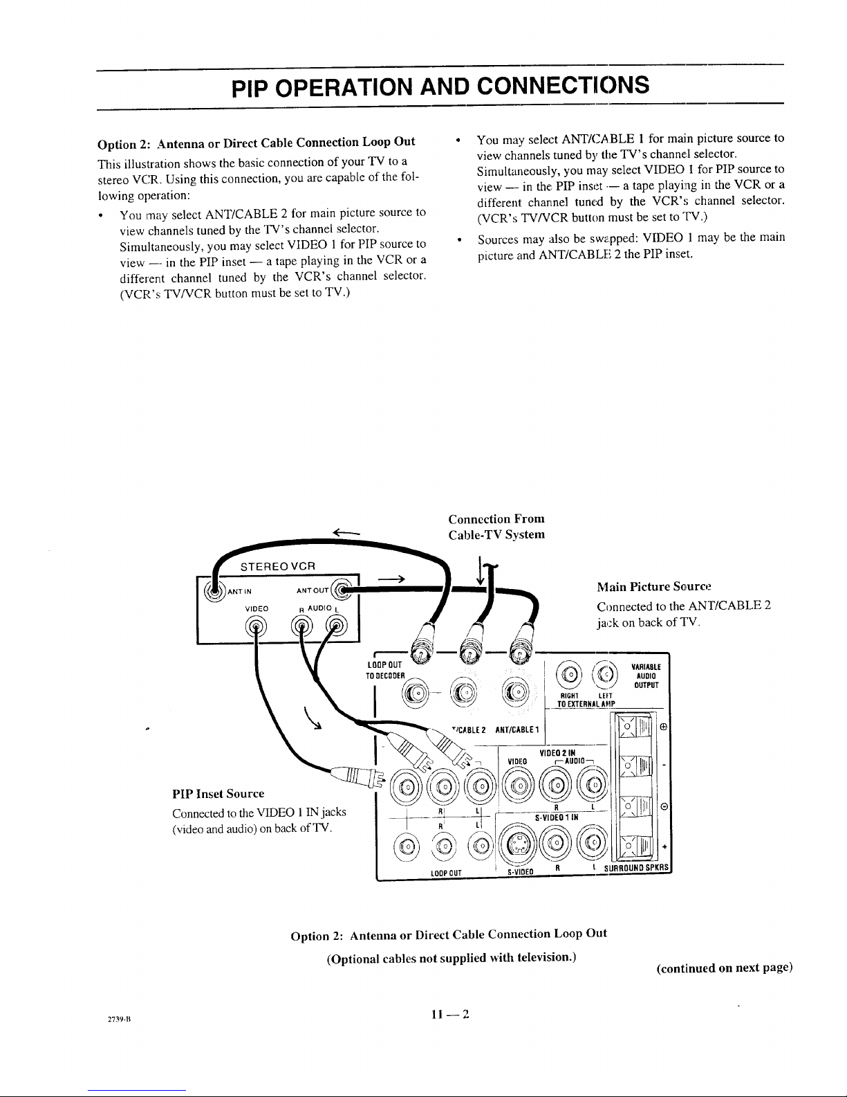
PIP OPERATION AND CONNECTIONS
Option 2: Antenna or Direct Cable Connection Loop Out °
This illustration shows the basic connection of your TV to a
stereo VCR. Using this connection, you are capable of the fol-
lowing operation:
• You may select ANT/CABLE 2 for main picture source to
view channels tuned by the TV's channel selector.
Simultaneously, you may select VIDEO 1 for PIP source to °
view --- in the PIP inset -- a tape playing in the VCR or a
different channel tuned by the VCR's channel selector.
(VCR's TV/VCR button must be set to TV.)
You may select ANT/CABLE 1 for main picture source to
view channels tuned by the TV's channel selector.
Simultaneously, you may select VIDEO I for PIP source to
view --- in the PIP inset --- a tape playing in the VCR or a
different channel tuned by the VCR',; channel selector.
(VCR's TV/VCR button must be set to "IV.)
Sources may also be swapped: VIDEO 1 may be the main
picture and ANT/CABLE 2 the PIP inset.
Connection From
Cable-TV System
STEREOVCR
ANTLN ANT OUT
VIDEO R AUOI_
_'___ VltlEn 2,@N
VIDEO r--AgOlO_
PIP Inset Source _ _c_)_ _) _)_j/
Connected to the VIDEO 1 IN jacks __ R, [_ R L
(video and audio) on back of TV. R_ _ S-VIDEO1IN
LOOPDUT
Main Picture Sc,urce
Connected to the ANT/CABLE 2
jack on back of TV.
VARIADLE
AUDIO
OUTPUT
-,I-.
R t SURROUNDSPKRS
Option 2: Antenna or Direct Cable Connection Loop Out
(Optional cables not supplied with television.)
(continued on next page)
2739-B 11 --2
Page 38

PIP OPERATION AND CONNECTIONS
Option 3: Cable Decoder Connection
This illustration shows the connection of both a cable-TV de-
coder anda stereo VCR to yourTV. Using this connection,
you are capable of, but not limited to, the following operation:
• You may select ANT/CABLE 2 for main picture source to
view unscrambled cable channels tuned by theTV.
Simultaneously, you may select VIDEO 1 for PIP source to
view --in the PIP inset -- a tape playing in the VCR or a
different channel tuned by the cable decoder. (VCR's
TV/VCR button set to VCR.)
• You may select ANT/CABLE 1for main picture source to
view premium cable channels tuned by the cable decoder.
(Tune TV to channel 3 or 4.)
Simultaneously, you may select VIDEO 1 for PIPsource to
view --- in the PIP inset -- a tape playing in the VCR.
(VCR's TV/VCR button set to TV.)
• Sources may also be swapped. In other words, VIDEO 1may
be the main picture source andANT/CABLE 1the PIP inset.
HOW TO SELECT MAIN PICTURt"
& PIP SOURCE
In order to watch a different picture in the PIP inset, you must
choose a different picture source than the one used for your
main TV picture. "Source" refers to the input jacks on the
back of your TV set from which the video and audio signals
are being received. These jacks correspond to 1:heselections in
the SOURCE MENU.
• ANT/CABLE 1or 2 (Input from antenna, direct cable con-
nection, or cable decoder)
• VIDEO 1,2 or3 (Input from VCR or camcorder)
• S-VIDEO 1 or 2 (Input fi'omSuper-VHS VCR)
(continued on next page)
Connection From
Cable-TV Decoder
<...._.
CABLE-TV DECODER
ANTIN
Main Picture Source
Connected to the ANT/
CABLE 1 or 2 jack on back
of TV.
Option 3: Cable Decoder Connection
(Optional cables not supplied with television.)
2736-0 11 -- 3
Page 39

PIP OPERATION AND CONNECTIONS
To Select Main Picture Source
The source, for the main picture can be either ANT/CABLE 1 or
2 connections, or any of the VIDEO connections. The follow-
ing example selects ANT/CABLE 1 for normal television
viewing, which is the most common setup.
1. Select TV mode of operation for the remote control.
2. Press SOURCE on the remote control repeatedly until
ANT/CABLE 1 is selected.
IANT/CABLE 1 I
ANT/CABLE 2
VIDEO 1
VIDEO 2
qrlIJFtEE S-WDEO1
VIDEO 3
S-VIDEO 2
To Select PIP Source
The PIP inset source can be either ANT/CABLE 1 or 2 con-
nections, or any of the VIDEO connections. The following ex-
ample selects VIDEO 1 for the PIP source, which is the most
common setup.
1. Select TV mode of operation for the remote control.
2. Press MENU on the remote until the PIP Menu is
selected.
CH 2 _]
12:30 |
SEO |
[VtP !VIDEOI [-1_
J
.
Source of main
picture
Source of PIP
Use SFLECT Up/Down to choose PIP SOURCE then
press SOURCE repeatedly to select VIDEO 1.
OH. GUIDE
I CH. REVIEW
PiP SOURCE
PIPCOLOR
PiP TINT
PIP SIZE
] [ VIDEO 1
4. Press ENTER to remove menus from the screen.
5. Press PIP on the remote to view the PIP inset.
6. Use the VCR to change the channel in the PIP inset,
or to view a tape in the PIP inset.
7. Use ADJUST Left/Right and SELECT Up!Down to
position the PIP inset anywhere on the TV screen.
PIP FUNCTIONS
P1P
Press PIP to display the PIP inset. Press PIP agaba to remove
inset.
Moving The Pip Inset Location
Use four-way arrows (ADJ/SELECT) to move PIP inset to the
desired location on the TV screen.
Swap
Press SWAP' to swap the main picture with the PIP inset. Press
SWAP again to return to the original display.
L___ Main Picture
Swap switches the Video
from the Main Picture to the
PIP inset and the PIP inset
to the Main Picture
PIP Size
Select PIP Size in the PIP Menu to choose between seeing a
large or small PIP inset.
Freeze
Press FREEZE to fi'eeze motion of the picture shown in the
PIP inset. Press FREEZE agahato return to a live PIP inset.
'9_en the PIP inset is not currently displayed, pressing
FREEZE provides an instant PIP freeze-frame of the program
you are watching. Press PIP again to return to normal TV
viewing. This function cart be used without a second source to
retain a phone number or fi-eezea football play.
1V
ADJ/ __
SELECT
PIP
SWAP _
C&_4NE
®0®
®@® 6}
LEARN PI _ FRE_JE MUTE
sw_ TIMER &EQ
_ I::]D (3D _
RECORO ST(_o PAL,_ SEARCH
REW PLff TV_,'CR
MODE
_SOURCE
FREEZE
Typical Remote
Your remote may differ from unit shown.
27s6-o 11 -- 4
Page 40

MAINTENANCE AND TROUBLESHOOTING
CARING FOR YOUR PROJECTION TV
Your projection TV will look better, have a longer life and per-
form better if you care for it properly.
First check to see that the TV is off. For added
safety, disconnect AC power to your TV.
NOTE: If you disconnect AC power to your TV
for an extended time period, you will have to reset
the clock.
Cabinet Care
Non-Wood Cabinet or Cabinet Components.
Moisten a soft cloth with a mild soap solution or Ivory dish-
washing detergent. Wipe the surface with a damp cloth. Then
rinse the cloth in clean water and wipe the surface again. Al-
low the TV to air-dry before turning it on.
Wood Cabinets or Cabinet Components.
Use any good furniture cleaner and polish. Regular care will
help preserve the finish.
Picture Screen Cleaning
Use a soft cloth moistened with warm water and rub lightly in
the soiled areas of the screen. DO NOT USE A TISSUE OR
PAPER TOWEL, AS THESE MAY DAMAGE SURFACE.
Wipe only in the vertical (up/down) direction (a',[ongthe
g':ooves). If there is a dirt buildup, a mild solution of warm
water and lvory dishwashing detergent may be used. Use dry
soft cloth to dry the screen. Care should be taken to avoid
scratches or damage to the screen surface.
NOTE -- The TV screen is easily damaged. Avoid acciden-
tal contact with the screen.
EXTENDED ABSENCE
Before an extended absence (such as a vacation) you may
want to disconnect AC power to your TV. This will protect
the projection TV from possible damage from lightning or
power line surges. If you have an outdoor antenna, you may
also want to disconnect the antenna from the wall plate con-
nection center
NOTE: If you disconnect AC power to your TV for an ex-
tended time period, you will have to reset the clock.
PICTURE INTERFERENCE
Your picture may be affected by interference caused by one or
a number of factors. These include:
Nearby Automobile Ignition, Electrical Appliances, etc.
Which causes a speckled, streaked picture. This is most notice-
able in weak signal areas.
Snow in Picture Caused by insufficient signal. Usually
caused by the TV being located too far from the TV station or
by an improper antenna installation.
Ghosts or Reflections Caused by signals being reflected
from surrounding building.,;, water tanks, or other high struc-
tures.
Radio Signal Police, amateur or CB radio transmitters may
cause interference.
These interference problems can often be corrected through
the use of a better antenna, signal amplifiers, or various filter
devices. See your 'IV dealer for additional irLformation, and ac-
cessories available for your projection TV.
ProcApa:2 12 -- 1
Page 41

MAINTENANCE AND TROUBLESHOOTING
BEFORE CALLING FOR SERVICE
Check these items and see if you can correct the trouble by
changing the adjustment of a control or the setting of a switch.
By making these simple checks before calling for service, you
may save time and money.
Problem
Picture OK. Poor sound.
Sound OK. Poor picture.
No picture or sound.
T]3_This
Re-orient ant'enn'a. Try another channel -- possible station
trouble. Check for local interierence. Check AUTO TUNING
and TUNING BAND options.
Re-orient antenna. Try another channel -- possible station
trouble. Adjust VIDEO Menu options with PICqVRE PREF.
in CUSTOM mode.
Is TV on? Is there power in wall outlet? Is TV plugged in? Is
antenna hooked up? Is cab'le hooked up? Is cable operational?
Check auxiliary audio/video equipment. Check channel
selection. Check TUNING BAND and AUTO TUNING
Menu options.
Picture blurred, ghost in picture, or distorted. Check antenna or cable hook up for broken wires or loose
connection. Try another channel _ possible station trouble.
Check for local interference.
No color, or poor color. Try another channel -- possible black and white program.
Check antenna or cable hook up for broken wires or loose
connection. Adjust VIDE() Menu options with PICTURE
PREF. in the CUSTOM mode. Is it a color program?
No sound. VOLUME (VOL) setting may be too low. Check MUTE
button operation on remote control, if provided. Is Speaker
EXT/INT switch in EXT po_ition?
Cannot select certain channels. Channels may be skipped in CH. ADD/DEL Menu option.
Check TUNING BAND and AUTO TUNfNG options.
Remote control does not work. Are batteries okay? ls TV tuJnaedON? Is TV plugged in?
No closed captions. Are captions available? Is CAPTION 1 or 2 selected by using
the CAPTIONS option on the SETUP Menu.
Black or blue box covers _'2of screen. Is text infoExnation available? Is TEXT 1 or 2 selected by
using the CAPTIONS option on the SETUP Menu?
No picture or sound when VCR source is selected. Is VCR hooked up properly9 Are wires connected to VCR-
. VIDEO 1/2jacks on comaection center?
No sound or weak stereo sound when using a stereo VCR. Check ALJDIO mode? Is it STEREO? Was stereo present
before selecting VIDEO 1/2 or S-VIDEO Source?
PIP is black when using VCR for PIP source, ls VCR hooked up properly'? Are wires connected to the
'VIDEO 1/2 input jacks on connection center? Is VCR selected
for PIP source?
PIP lacks contrast when using VCR for PIP source, iIsVCR hooked tip properly? Are wires cormec_:edto the
'VIDEO 1/2 input jacks on connection center?
PIP inset flame is snowy when using TV tuner for PIP and Is TV/VCP switch on VCR in the TV position?
VCR for main picture.
Jl ii
Always request that your technician use only genuine Zenith
exact replacement parts for continued quality and safety per-
formance. Keep your Zenith ALL Zenith.
NOTE: Ifyour TV fails to respond to any other menu selec-
tion, you must reset the TV Simply discortnect the AC power.
Wait a few minutes, then reconnect the AC power.
2736-o 12 _ 2
Page 42

PRODUCT REGISTRATION CARID
You could win a full refund on your new Zenith product.
Look for the Product Registration Card on your new video
product.
Each month a drawing is held by Zenith from the completed
Product Registration Cards received during the preceding
month. Zenith will reimburse the winner for the full purchase
price of the product purchased.
Inorder to participate, simply complete andreturn the Product
Registration Cardatonce, even if you choose not to complete
the information and interests portion of the questionnaire.
The odds of winning the free drawing described above, de-
pend on the number of participants. Free drawing offer is
void in Canada and other places where restricted or prohib-
ited by law. Offer is void for Hotel/Motel and Institutional
models. Rental models are not eligible.
Product Card lost or misplaced?
The Product Registration Card furnished with your video prod-
uct is pre-printed with its Model and Serial mmabers. Please
fill out the card and mail it at your earliest co:avenience. It is
imperative that Zenith know how to reach yoa promptly if we
discover a safety problem that would affect you. If the original
card has been lost or misplace,J, you may use the replacement
card provided below. Either card will qualify you for the free
drawing, but you are limited to only one entry in _:hedrawing.
Complete the card, place it in an envelope and mail it to:
Zenith Electronics Corporation
P. O. Box 173257
Denver, CO 80217-3257
Use the replacement Product F'egistration Ca_:donly if the
original card has been misplaced or lost.
PHOTOCOPY AND CUT ALONG DASHED LINE
..=...=.o • ====. • • • ========.========• ==1 • • ====================== =. • • • • • •===.,,•===••=====_• =• ============== 1.. •. • =.= • M= • ==.
Zenith Product Registration Card H5Z01-01
L__Please Print Clearly or Type (_ Area Code Telephone
1. DMr. 2. (--]Mrs. 3. [_ Ms. 4. DMiss 2_/LI I I-I I I I J
First Name Initial Last Name
I!IIIII!IIIUIIIIIIIII
Street
IIIIIIIIIIIIIit111_111
City
IIIIIIIIIIIIIIII ®
State Zip Code
111111111-11111
I_11111
Apt. No.
I1_ Illl
Date of Purchase
Mo. Oay Yr.
L_L_II__L_IIll
.OOEL t I
NUMBER
Copy Numbers Here
From Label on Set
NUMBER
Please record the model number
4[=.=.m and serial number from the sticker
on the back of your set.
m=......=..= •=.= • • • • • = = • • • • • • ==• .• =• • ..• • • • •m=.=.nm •.===.n......=..==.• • • • • •.,. •..=..=. • • • === =.====.======.=m=• ===.======''_
TVCARD3
Page 43

BROKENORLOSTREMOTECONTROl.?
ForanExactReplacementRemote
Controlfor your newZenithTelevision,
seeyour localZenithDealeror order
directbycalling1-800.-255-6790.To
assurethecorrectremotefor your new
Zenith,pleasehaveyourtelevision'smodel
andserialnumberanddateof purchaseready!
ONLY$39.95
OTHERFINEACCESSORIESFORYOURTELEVISION.
A WALLMOUNTS IfyourTV Order
Illtll (17 Ibs.) screenis: this model
IIIitil •Easyto install 1_" _ ONLY
nllil • Safeandstrong --
IIIJil :5 yearwarranty $69.95
_1111 MadeinU.S.A. 19/20"
[]_| • S_acesaving CWM020 ONLY
IlU_I, • ULlisted $89.95
• Adjustabletiltangle: 95127" CWM027 ONLY
$99.95
To order these fine accessories,
pleasefill out this card and
return a photocopy to:
Attn: Accessory Offers
Zenith VideoTechCorporation
1900 N."AustinAvenue
Chicago, IL 60639
or call1-800-255-6790
E-I Check or moneyorder
(MadepayabletoZenithVideoTechCorp.)
DILUXE AMPLIFIED 75 OHM
INDOORTV ANTENNA.
• Provides sharp, clear pictures
• VHF/UHF color & FlVlstereo reception
• VHF!UHF signal combiner circuitry
• includes:
,,Matching transformer
,,4 ft. coaxial cable with connectors
• Designed and built in the U.S.A.
ATS 750 ONLY$59.95
PHOTOCOPYPAGEANDDETACHHERE
ITEM NUMBER DESCRIPTION
Sales Tax: Please add your state sales tax ifyou
live in one of the following states.
I A 7 3/4%,GA4%,I!.8314%.KS4.9%,KY6%,ME8%,PA8%,RI7%,TX 7 3t4%,VA4 1/_, WA6 1/2%.
E-] Visa [] Mastercard
Account#
F - 1 11
ExpirationDate: Signature:
13UANTITYPRICEPERITEM
SUBTOTAL
STATESALESTAX
SHIPPING& HANDLING
TOTALAMOUNTOFORDER
TOTAL
PRICE
$4.50
SHIPTO:
Telephone: )
Name:
IMPORTANT:PLEASEBESURETO COMPLETETHEINFORMATIONBELOW.
TVModelNumber
(fromstickeronbackofunit)
/ /
"lVSeriaINumber Mo. Day Yr.
(fromstickeronbackofunit) (Approx.dateofpurchase.)
PLEASEALLOWUPTO3WEEKSFORDELIVERY.THANKYOU!
T',/t, qr'qq
Address:
Apt.#
State
City
ZipCode
NOTE:Priceandavailabilitysubjecttochange.
Page 44

Page 45

YOUR ZENITH WARRANTY
Consumer Protection Plan for Zenith Projection TV
Welcome into the Zenith family! We believe that you will be
pleased with your new Zenith Projection TV. Please read this
Consumer Protection Plan carefully. It is a "ONE YEAR
FULL WARRANTY," plus a limited second year picture tube
warranty, as defined under federal law. This warranty gives
you specific legal rights, and you may also have other rights
that vary from state to state within the U.S.A.
Zenith's Responsibility
Service Labor and Parts -- During a period of one year
from effective warranty date, Zenith will supply new or re-
manufactured replacement picture tubes or other parts, and
will pay for service labor by a Zenith distributor or
distributor-approved Zenith service center, when such parts or
service labor are needed to repair the product as a result of
manufacturing defects. Further, Zenith will supply a new or re-
manufactured replacement for any picture tube which fails dur-
ing the second year after effective warranty date because of a
manufacturing defect. Replacement parts are warranted for the
remaining portion of the original warranty period. The above
service labor warranty applies only in the U.S.A.
On-Site Service -- Warranty service is provided when the
Projection TV is installed.
Not Covered -- This warranty covers manufacturing defects
and doe.,; not cover installation, adjustment of customer con-
trols in the home, installation or repair of home antenna sys-
tems, cable converters or cable company-supplied equipment;
it also does not cover damage due to misuse, abuse, negli-
gence,-acts of God or other causes beyond the control of Ze-
nith. Any alteration of the product after manufacture voids this
warranty in its entirety.
Owner's Responsibility
Effective Warranty Date ---Warranty begins on the date of
original consumer installation. For your convenience, keep the
dealers dated bill of sale or ddivery ticket as evidence Of the
purchase date.
Operating Guide -- Read your Operating Guide carefully so
that you will understand the c,peration of your set and how to
adjust the customer controls.
Antenna -- Reception problems caused by inadequate home
antennas or faulty antenna connections are the owner's respon-
sibility.
Important: Product Registration -- Please fill out and mail
your Owner Registration Card. It is imperative that Zenith
know how to reach you pron:ptly if we should discover a
safety problem that could affect you.
Warranty Service- For warranty service information, con-
tact your Ze,nith dealer preferably, or any distributor-
approved _nith service cenler. Parts and service labor that are
Zenith's responsibility (see _bove) will be provided without
charge. Other service is at th_ owner's expense. If you have
any problera in obtaining satisfactory warranty ,service, write:
Zenith Electronics Corporation
Customer Service Departmenl
1000 Milwaukee Avenue
Glenview, IL 60025-2493
Telephone: (8L.7) 391-8752
Mon-Fri, 8:00 a.m. - 4:30 p.m. Central Time
NOTE: Before you ask for Warranty service, check
the Operating Guide section entitled, "MAINTE-
NANCE AND TROUBLESHOOTING.'" It may be
possible to avoid a service call
PROWARR3
Page 46

ZENITH ELECTRONICS CORPORATION
1000 MILWAUKEE AVENUE
GLENVIEW, ILLINOIS 60025
Part No. 206-2739
Printed in U.S.A.
EP-ED
 Loading...