

Page 1
!_Advanced Video Imaging
recycted paper
OPERATING GUIDE AND WARRANTY
DDI DOLBY SURROUND]
Projection ,Color"rv
MTS Stereo
Picture-In-Picture
Closed Captions
Universal Remote Control
Return the Product Registration
Card, and your P/could be free!
Page 2
WARNING:
TO REDUCE THE RISK OF ELECTRIC SHOCK DO NOT
REMOVE COVER (OR BACK). NO USER SERVICEABLE
PARTS INSIDE. REFER TO QUALIFIED SERVICE
PERSONNEL.
TO PREVENT FIRE OR SHOCK HAZARDS, DO NOT
EXPOSE THIS PRODUCT TO RAIN OR MOISTURE.
The lightning flash with arrowhead symbol, within an equilateral
triangle, is intended to alert the user to the presence of uninsulated
"dangerous voltage" within the product's enclosure that may be of
sufficient magnitude to constitute a risk of electric shock to
persons.
The exclamation point within an equilateral triangle is intended to
alert the user to the presence of important operating and
maintenance (servicing) in,;tructions in the literature
accompanying the appliance.
Safety Tips
Refer to the "Safety Tips" booklet that came with your
product for important safety considerations.
Power-Cord Polarization
This product is equipped with a polarized alternating-
current line plug (a plug having one blade wider than the
other.) This plug will fit into the power outlet only one
way. This is a safety feature. If you are unable to insert
the plug fully into the outlet, try reversing the plug. If the
plug should still fail to fit, contact your electrician to
rep!ace your obsolete outlet. Do not defeat the safety
purpose of the polarized plug.
Note to Cable TV System Installer
This reminder is provided to call the cable TV system
installer's attention to Article 820-40 of the NEC that
provides guidelines for proper grounding and, in
particular, specifies that the cable ground shall be
connected to the groundi_ag system of the building, as
close to the point of the cable entry as practical.
CAUTION
To prevent electric shock, match wide blade of plug to
wide slot, fully insert.
ATTENTION
Pour 6viter les chocs 61ectriques, introduire la lame la
plus large de la fiche dans la borne correspondante de la
prise et pousscr jusqu'au fond.
Copyright © Zenith Electronics Corporation 1992, -TVWARN1
Page 3

CONTENTS
INTRODUCTION
Welcome ........................................... ii
Installation Considerations ........................... ii
CONNECTIONS FOR YOUR TV
Connection Center On Back Of TV .................. 1-1
Input Sources For Your TV ......................... 1-2
Step 1. Make Basic Connections To TV .............. 1-2
Step 2. Make VCR Connections To TV ............... 1-4
Step 3. Make Super-VHS Connections To TV ......... 1-5
Step 4. Make Stereo Audio Connections
To Audio Amplifier ............................. 1-6
Step 5. Make External Speaker Connections to TV ..... 1-7
Step 6. Make Surround Sound Connections To TV ..... 1-7
Step 7. A/V Connections To Auxiliary A/V Jacks ...... 1-8
Step 8. Make Connections To Fixed A/V Jacks ........ 1-8
THE FIRST TIME YOU OPERATE YOUR TV
Step 1. Connect The Power ......................... 2-1
Step 2. Turn TV On ............................... 2-1
Step 3. Select Your Viewing Source .................. 2-1
Step 4. Use Auto Ch. Search ........................ 2-1
Step 5. Use Other Options .......................... 2-2
OPERATING YOUR TV
Basic TV Operations .............................. 3-1
Sleep Timer ...................................... 3-1
GETTING TO KNOWYOUR TV
Location of User Items ............................. 4-1
Front Panel Controls .............................. 4-2
REMOTE CONTROL MODEL SC2300
Operation ......................................... 5-1
Installing Batteries ................................ 5-1
REMOTE CONTROL MODEL LR4455
Operation ........................................ 6-1
Choose The Operating Mode ....................... 6-1
TV Operations .................................... 6-2
VCR Operations .................................. 6-3
Cable-TV Operations .............................. 6-4
Preparation For Use ............................... 6-5
Installing Batteries ................................ 6-5
Three Ways to Customize Your Remote .............. 6-6
Programming Brand Codes ......................... 6-6
TV, VCR And Cable-TV Operating Codes ........... 6-7
Auto Find Mode .................................. 6-8
Erase Mode ...................................... 6-8
Learning Mode ................................... 6-9
ON-SCREEN MENUS
Available Menus .................................. 7-1
Summary Of Menu Items ........................... 7-1
Basic Menu Operation ............................. 7-2
SOURCE MENU
To Select A Source ................................. 8-1
SETUP MENU
Auto Ch. Search ................................... 9-1
CH. Add/Del ..................................... 9-2
CH. Labels ....................................... 9-2
Tuning Band ...................................... 9-3
Auto Fine Tune .................................... 9-3
Clock Set ............................................ 9-4
Captions ........................................... 9-4
CH. Background ..................................... 9-5
Projo Setup ........................................ 9-6
Se,tup Menu With Auxiliary
Video Source Selected ........................... 9-6
AUDIO MENU
General Information .............................. 10-1
Bass ............................................ 10-1
Treble .......................................... 10-1
Balance ......................................... 10-1
Audio ............................................ 10-2
SEO ............................................. 10-2
Surround ........................................ 10-2
Null ............................................. 10-2
Audio Selection Considerations ..................... 10-3
VIDEO MENU
Contrast ......................................... 11-1
Brightness ....................................... 11-1
Color ............................................ 11-1
Tint ................................................ 11-1
Sharpness .......................................... 11-1
Color Temp ......................................... 11-1
Video Filter ....................................... 11-1
Auto Flesh ........................................ 11-1
Picture Pref ....................................... 11-1
PIP OPERATION AND CONNECTIONS
Picture-In-Picture ................................ 12-1
Connection Alternatives ........................... 12-1
How To Select Main Picture &
PIP Source ..................................... 12-2
PIP Function,; ..................................... 12-3
MAINTENANCE AND TROUBLESHOOTING
Caring For Your Projection TV ..................... 13-1
Extended Absence ................................ 13-1
TV Picture Interference ........................... 13-1
Befl)re CaUing For Service ......................... 13-2
VCR Operational Mode Charl:s ..................... 13-3
Product Registration Card
Recommended Accessories For Your Television
Your Zenith Warranty
Page 4
INTRODUCTION
WELCOME
Welcome into the family of Zenith Color Television owners.
This guide provides instructions on how to operate your
new TV. It is supplemented by a booklet containing Safety
Tips. We urge you to read these publications carefully so
that you will receive full enjoyment from your new Zenith
TV for many years to come.
Your new Zenith TV has been designed and built to give
you the very best in quality, features and performance.
There are many regional Zenith distributors and thousands
of distributor-approved Zenith service centers throughout
the U.S. and Canada who can attend promptly and effective-
ly to ordinary service needs.
If you should have an unusual performance or service problem
that cannot be satisfactorily resolved by your distributor-
approved Zenith service center, contact the regional Zenith
distributor in your area, or write:
Zenith Electronics Corporation
Customer Service Department
1000 Milwaukee Avenue
Glenview, IL 60025-2493
Telephone: (847) 391-8752
Mon-Fri, 8:00 a.m. - 4:30 p.m. Central Time
Send the model number, serial number, and date of pur-
chase or original installation, with a fttllexplanation of the
problem and the service _;tory. We will welcome the op-
portunity to look into your specific question or problem and
to be of assistance in resolving it promptly.
The model and serial nunltx_rsofyour newTV are located on
the back of the TV cabine,t. !For yourfuture convenience and
protection, we suggest that you record these numbers here:
Model No.
Serial No.
Manufactured under license t-ore Dolby Laboratories Licensing Corpora-
fion. Additionally licensed under one or more of tlhe following patents:
U.S. number 3,959590; Canadiian numbers 1,004,6(]3 and 1,037,877.
"Dolby" and the double-D syrabol are trademarks of Dolby Laboratories
Licensing Corporation.
INSTALLATION CONSIDERATIONS
Before you install your TV...
Ventilation - Proper ventilation keeps your TV
running cool. Air circulates through perfora-
tions in the back and bottom of the cabinet. Do
not block these vents or you will shorten the life
of your TV.
Power Source - Your TV is designed to operate
on normal household current, 120 volt 60 Hertz
AC. Do not attempt to operate it on DC current.
Power Cord - Your power cord has a
polarized plug as required by Underwriters'
Laboratories. It has one regular blade and one
wide blade and fits only one way into a standard
electrical outlet. If the blades will not enter
either way, your outlet is very old and non-
standard. A new outlet should be installed by a
qualified electrician.
Safe Operation - Your TV is manufactured
and tested with your safety in mind. However,
unusual stress caused by dropping or mishan-
dling, exposure to flood, fire, rain or moisture,
or accidental spilling of liquids into the TV, can
result in potential electrical shock or fire
hazards. If this happens, have your TV checked
by a service technician before using it again.
Please read and observe each safety point in the "Safety
Tips" folder when installing and using your TV.
FIXED PATrERN DISPLAY CAUTION - If you use your
TV for video games, telete,xt or other fixed displays, avoid
setting the BRIGHTNESS control for an excessively bright
picture. A bright, fixed pattern, if used fi_r leng periods of
time, can result in a permanent imprint on the TV picture
tube. You can reduce this possibility by alternating the use
of the fixed pattern display with normal TV picture viewing,
by turning down the CONTRAST control for sustained
fixed pattern use, and by turning off the f'txed pattern dis-
play when not in use.
PLUGGING IN YOUR T¢ -- Be sure to plug your TV into
an "unswitched" AC power source. The "s_itched" AC out-
lets found on some video equipment wilt not continue sup-
plying porter to the TV once the equipment is turned off. If
the power to the TV is _nterrupted, you willhave to reset
the clock in the TV to the current time.
ii cs_w_
Page 5

CONNECTIONS FOR YOUR TV
CONNECTION CENTER ON BACK OF "iV
The connection center on the back of your TV will be
similar to the one shown below. These connections allow
three basic "types" of video inputs to provide for up to 5 dif-
ferent viewing sources to your TV.
LOOP OUT
TOI_EGOOER
q
Using these five cx)nnections, you can choose from a variety
of antenna sources and audio/video components for your
viewing pleasure. Note that the correct source must be
selected from the SOURCE MENU (as described later in
this booklet) to watch TV. Refer to the illustration while
reading the following descriptions.
@
q
®
]1. ANT/CABLE 1 or ANT/CABLE 2
Use one of these jacks for 75-ohm, antenna-type
signal connections to your TV. Attach your anten-
na, cable-TV line, or other video component to
either of these jacks. The input may come from an
outdoor or master antenna, cable-TV decoder box,
or the 75-ohm TV output from a VCR.
2:. LOOP OUT
Use th'is output jack to route the cable-TV signal
back to the decoder supplied by your cable-TV
system. When connected as shown in Steps 1C and
1D, you can view basic (unscrambled) cable chan-
nels by selecting the ANT/CABLE 2 source or
premium (scrambled) cable channels tuned by the
decoder by selecting ANT/CABLE 1 source.
3. VIDEO 1 IN or VIDEO 2 IN
Video and audio (Base Band) input from VCR or
other video component (Disc Player). Gives im-
proved picture quality performance over that ob-
tained through the ANT/CABLE jacks.
4. VIDEO 1 LOOP OUT
Use these jacks to send the incoming video and
audio signals (from VIDEO 1 IN) to another com-
ponent such as a second VCR or TV monitor.
S-VIDEO R t EXTERNAL SPKRS
5. S-VIDEO I IN
Input from a Super-VHS VCR. Both left and right
audio jacks are provided as well as the S-Video
(Y-C) jack.
6. EXTERNAL SPEAKERS
Terminals for connecting external left and right
stereo speakers.
7. EXTERNAL AMP
Standard Phono Jack connectors foJr output to an
external amplifier.
8. SURROUND SPEAKEB:
Standard Phono Jack connector for output to op-
tional surround sound speakers.
9. :SPEAKERS INT/EXT
Use this :switch to turn the TV's internal speakers
OFF or ON when an external audio anaplifier or
external .,;peakers are connected to 1:he TV. (See
.,;teps 4 and 5.)
26,;go 1 - 1
Page 6
CONNECTIONS FOR YOUR IV'
INPUT SOURCES FOR YOUR TV
Your TV has five input connection areas: ANT/CABLE 1,
ANT/CABLE 2, VIDEO 1 IN, VIDEO 2 IN, and S-
VIDEO 1 IN. (In addition, some models have a sixth input
area on the back of the TV near the top.) These five inputs
allow you to connect five different "signal sources" to your
TV at the same time. The "Signal Source" refers to the
item supplying the picture and sound to your TV.
The most common "signal source" is your outdoor antenna
(or master antenna) or a cable-TV system. This type of sig-
nal is called a radio frequency (RF) source, and is con-
nected to the one of the ANT/CABLE jacks.
STEP 1. MAKE BASIC CONNECTIONS TO TV
There are four basic hook ups to your TV; outdoor antenna
(or master antenna) with or without VCR, and cable-TV
system with or without VCR. Select the hook up that best
fits your needs. See the following diagrams.
Your connection is made to one of the ANT/CABLE jacks
on the back of the TV. These jacks accept 75-ohm cable ter-
minated in an F-type male connector. You may want to do
the hook-up yourself, or call a TV service technician, or a
cable company.
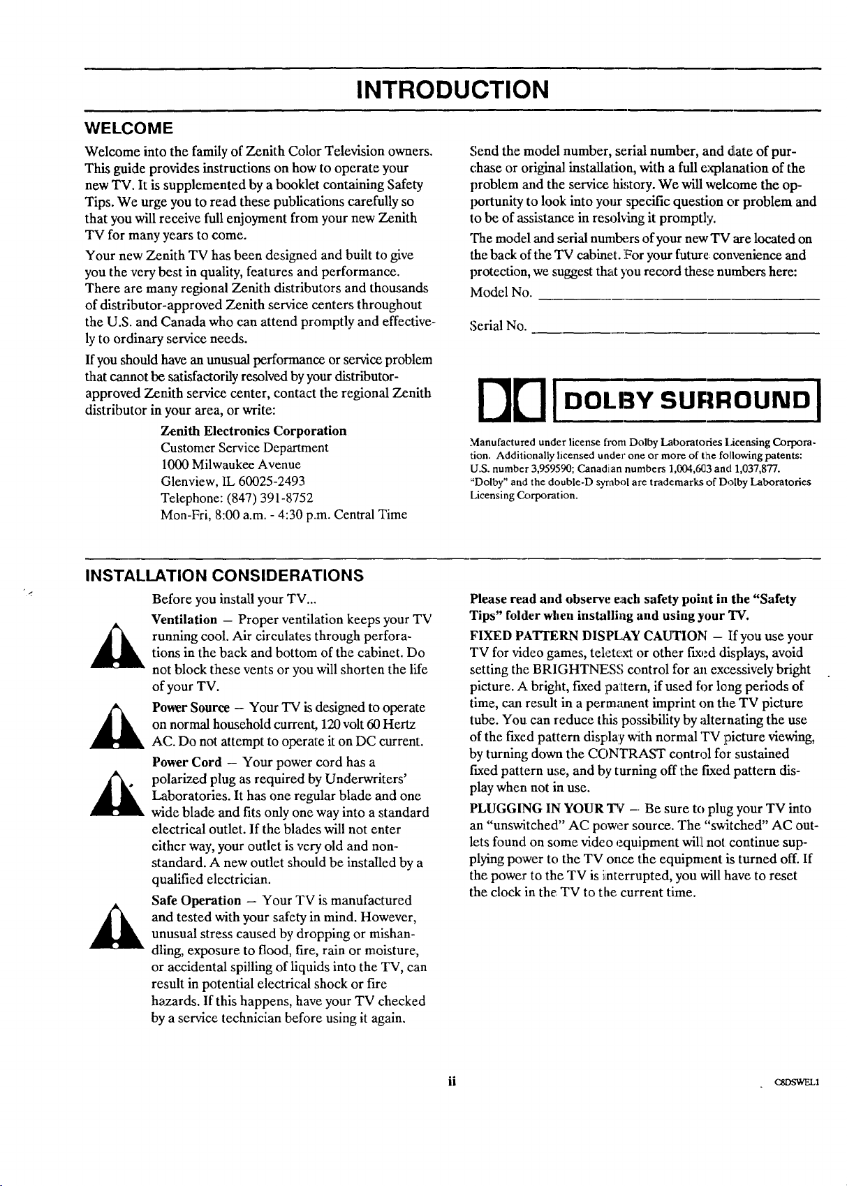
A. Antenna Connection to TV
If You Have a Round Antenna Wire:
Connect the 75-ohm round antenna wire to either
the ANT/CABLE 1 or ANT/CABLE 2 jack on the
TV.
If You Have a Flat, Twin-Lead Antenna Wire:
Use the 300/75 ohm adapter included with the TV.
Attach the ends of the wire to the adapter and plug
it into either the ANT/CABLE 1 or the
ANT/CABLE 2 jack.
Another common "signal source" is the audio and video
(A/V) from a VCR or video disc player. This _q0e of signal
is called base band (basic vicleo and audio'.),and is con-
nected to one of the VIDE() IN connections.
A third "signal source" is the input from a Super-VHS
VCR. If you have a S-VIqS VCR, use the S-Vl[DEO 1IN
video and audio jacks to connect it to the TV.
To use any of these video!audio input sources, you must ac-
cess the SOURCE Menu arm select the "source" which cor-
responds to the input jacks 'being used. Refer to the
"SOURCE MENU" in this operating guide.
300/75 ohm
Flat Wire
Round Wire
LOOP OUT ANT/CABLE 2 ANT/CABLE 1
TO DECODER
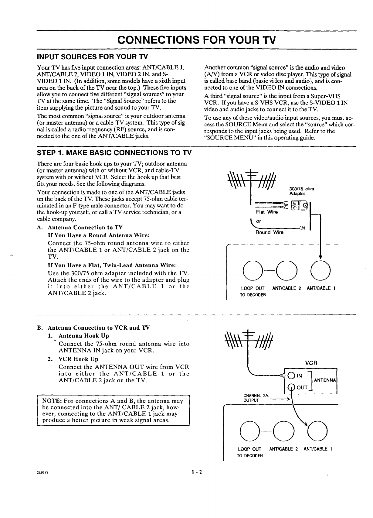
B° Antenna Connection to VCR and TV
I. Antenna Hook Up
Connect the 75-ohm round antenna wire into
ANTENNA IN jack on your VCR.
2. VCR Hook Up
Connect the ANTENNA OUT wire from VCR
into either the ANT/CABLE I or the
ANT/CABLE 2jack on the TV.
NOTE: For connections A and B, the antenna may
be connected into the ANT/CABLE 2 jack, how-
ever, connecting to the ANT/CABLE 1 jack may
produce a better picture in weak signal areas.
w0-o 1 - 2
'VCF!
.__. _OIN 7ANTENNA
CHANNEL 3/4
OU/PUT
LOOP OUT ANTICABLE 2 ANTICABLE 1
TO DECOOEIR
Page 7
,, CONNECTIONS FOR YOUR TV
STEP 1. MAKE BASIC CONNECTIONS TO TV (CONTINUED)
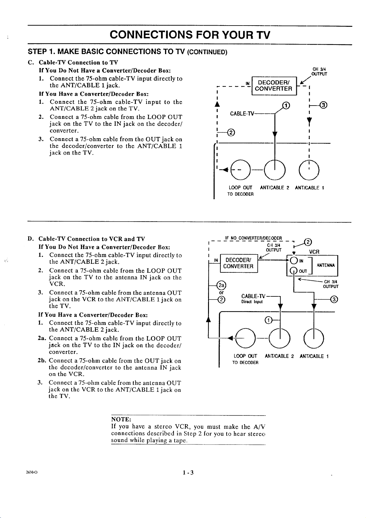
C. Cable-TV Connection to TV
If You Do Not Have a Converter/Decoder Box:
1. Connect the 75-ohm cable-TV input directly to
the ANT/CABLE 1 jack.
If You Have a Converter/Decoder Box: I
1. Connect the 75-ohm cable-TV input to the •
ANT/CABLE 2 jack on the TV.
2. Connect a 75-ohm cable from the LOOP OUT
jack on the TV to the IN jack on the decoder/
converter.
3. Connect a 75-ohm cable from the OUT jack on
the decoder/converter to the ANT/CABLE 1
jack on the TV.
I
I
I
I
F--o
!
!
IN
CONVERTER
DECODER/ t___
CABLE-I'Ve---
LOOP OUT ANTI,CABLE 2 ANTK,ABLF I
TO DECODER
CH 314
OUTPUT
I
I
T
I
I
I
I
I
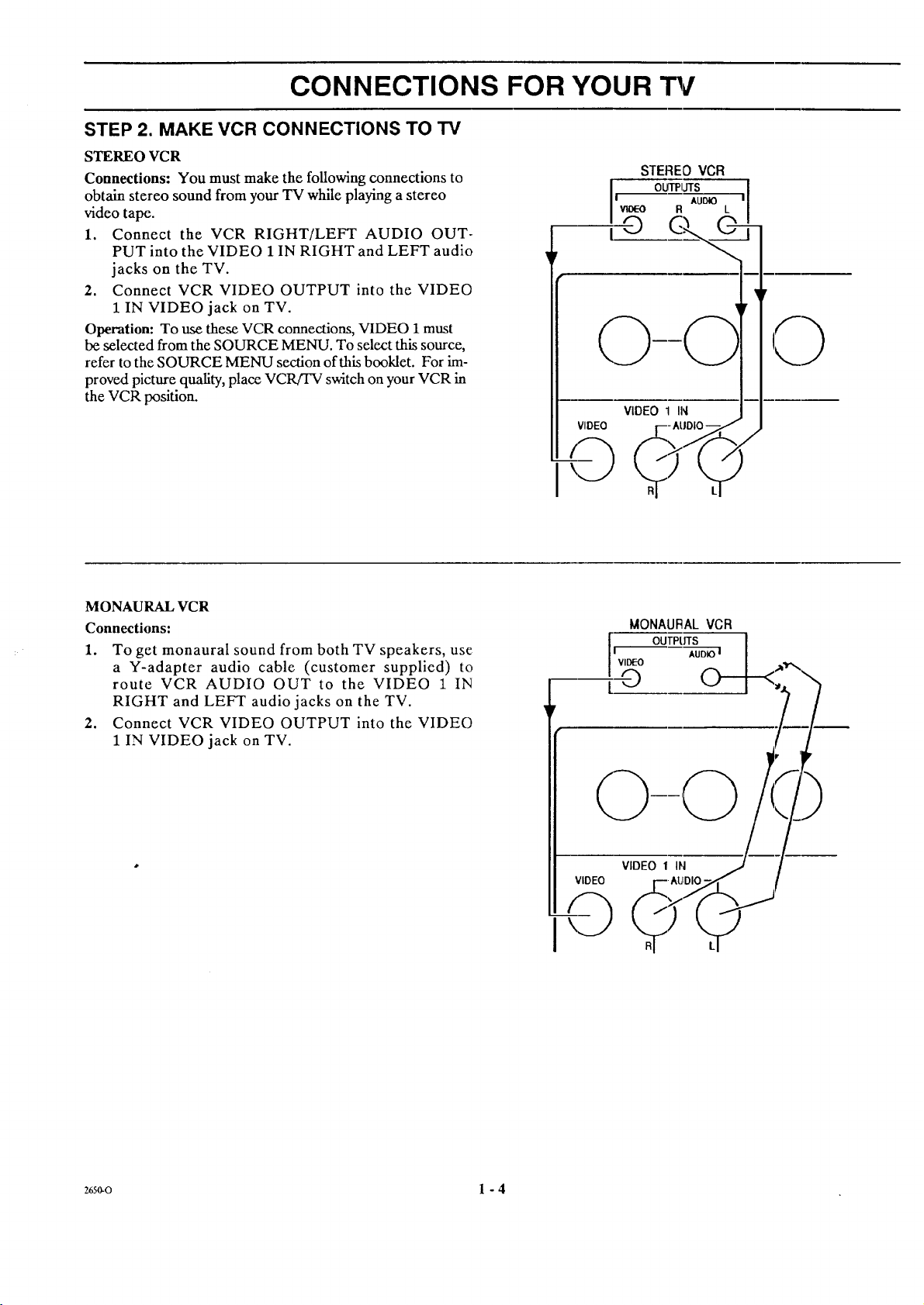
D. Cable-TV Connection to VCR and TV
If You Do Not Have a Converter/Decoder Box:
1. Connect the 75-ohm cable-TV input directly to
the ANT/CABLE 2 jack.
2. Connect a 75-ohm cable from the LOOP OUT
jack on the TV to the antenna IN jack on the
VCR.
3. Connect a 75-ohm cable from the antenna OUT
jack on the VCR to the ANT/CABLE 1jack on
the TV.
If You Have a Converter/Decoder Box:
1. Connect the 75-ohm cable-TV input directly to
the ANT/CABLE 2 jack.
2a. Connect a 75-ohm cable from the LOOP OUT
jack on the TV to the IN jack on the decoder/
converter.
2b. Connect a 75-ohm cable from the OUT jack on
the decoder/converter to the antenna IN jack
on the VCR.
3. Connect a 75-ohm cable from the antenna OUT
jack on the VCR to the ANT/CABLE 1 jack on
the TV.
IF NO CONVERTER/DEC;ODER
C_t3/4
OUTPUT
CONVERTER
DECODER/ ["e'/
LOOP OUT ANT/CABLE 2
TO DECODER
AN'FICABLE 1
NOTE:
If you have a stereo VCR, you must make the A/V
connections described in Step 2 for you to hear stereo
sound while playing a tape.
_s_o 1 - 3
Page 8
CONNECTIONS FOR YOUR
STEP 2. MAKE VCR CONNECTIONS TO TV
STEREO VCR
Connections: You must make the following connections to
obtain stereo sound from your TV while playing a stereo
video tape.
1. Connect the VCR RIGHT/LEFT AUDIO OUT-
PUT into the VIDEO 1 IN RIGHT and LEFT audio
jacks on the TV.
2. Connect VCR VIDEO OUTPUT into the VIDEO
1 IN VIDEO jack on TV.
Operation: To use these VCR connections, VIDEO 1must
be selected from the SOURCE MENU. To select this source,
refer to the SOURCE MENU section of this booklet. For im-
proved picture quality, place VCR!TV switch on your VCR in
the VCR position.
MONAURAL VCR
Connections:
1. To get monaural sound from both TV speakers, use
a Y-adapter audio cable (customer supplied) to
route VCR AUDIO OUT to the VIDEO 1 IN
RIGHT and LEFT audio jacks on the TV.
2. Connect VCR VIDEO OUTPUT into the VIDEO
1 IN VIDEO jack on TV.
STEREOVCR
I'_ AUOlO
woeo R L
l OUTPIJTS
i©
VIDEO 1 IN
VIDEO
MONAURAL VCR
OUTPtffS I
_,r--_-----_[_<_*x
26so-o 1 - 4
Page 9
CONNECTIONS FOR YOUR "i%r
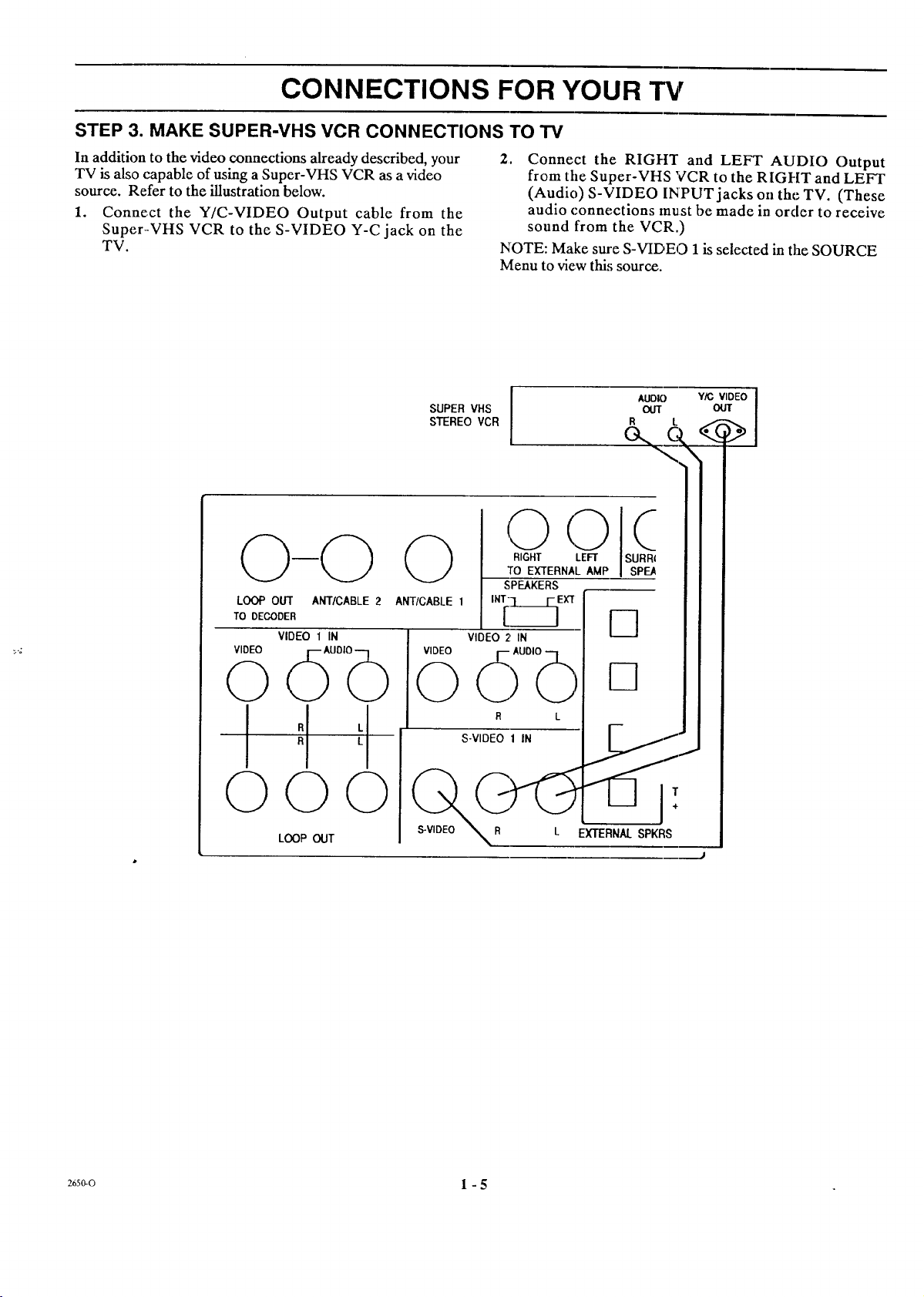
STEP 3. MAKE SUPER-VHS VCR CONNECTIONS TO TV
In addition to the video connections already described, your
TV is also capable of using a Super-VHS VCR as a video
source. Refer to the illustration below.
1. Connect the Y/C-VIDEO Output cable from the
Super.-VHS VCR to the S-VIDEO Y-C jack on the
TV.
LOOP OUT ANT/CABLE 2
TO DECODER
VIDEO 1 IN
VIDEO
2. Connect the RIGI-t'r and LEFT AUDIO Output
from tile Super-VHS VCR to the RIGHT and LEFT
(Audio) S-VIDEO INPUT jacks oil the TV. (These
audio connections must be made in order to receive
sound from the VCR.)
NOTE: Make sure S-VIDEO 1is selected in tim SOURCE
Menu to view this source.
0
0
Uo,b
I
R
O0
L_P _T
,.zso-o 1 - 5
Page 10
CONNECTIONS FOR YOUR TV
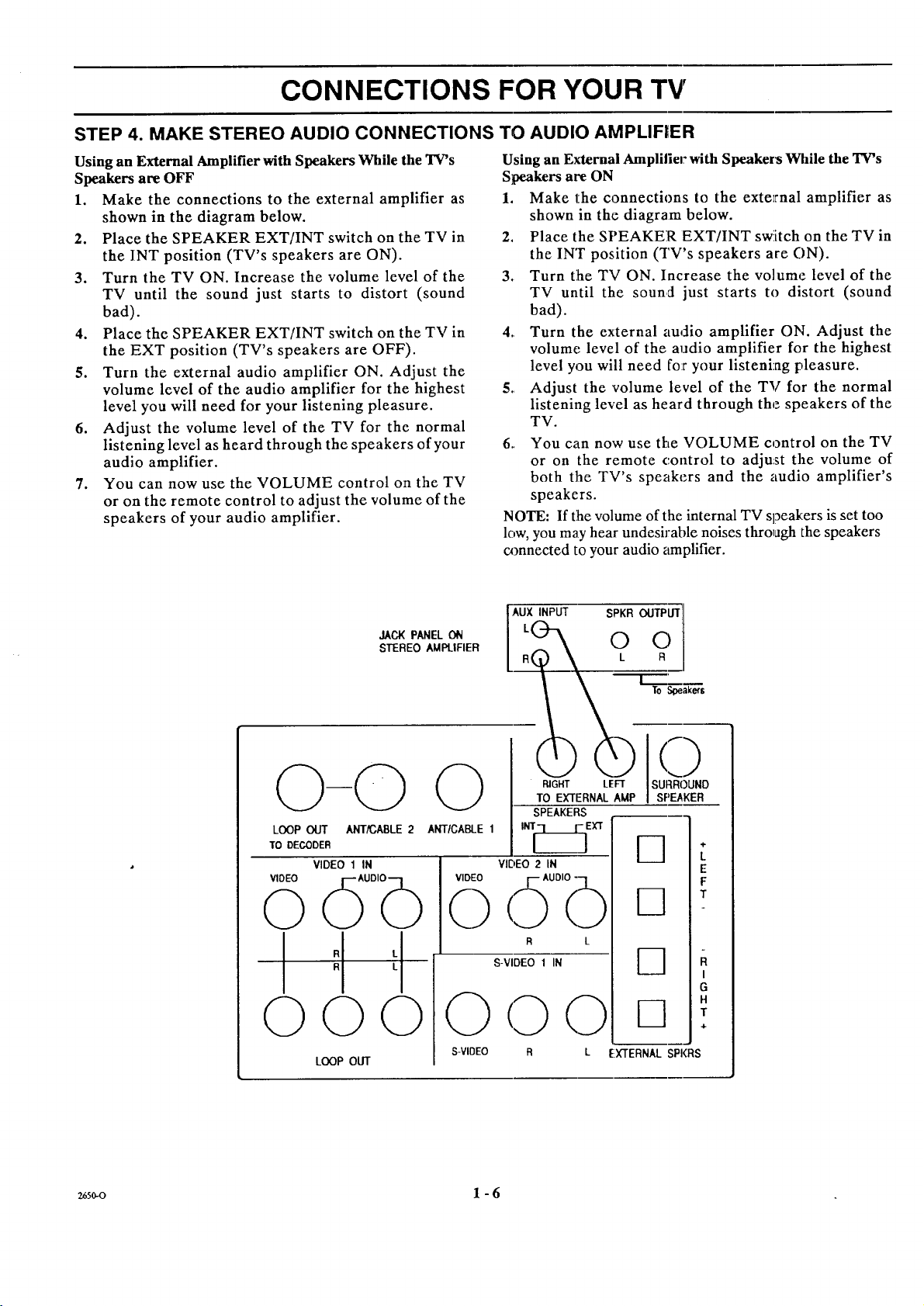
STEP 4. MAKE STEREO AUDIO CONNECTIONS TO AUDIO AMPLIFIER
Using an External Amplifier with Speakers While the TV's
Speakers are OFF
1. Make the connections to the external amplifier as
shown in the diagram below.
2. Place the SPEAKER EXT/INT switch on the TV in
the INT position (TV's speakers are ON).
3. Turn the TV ON. Increase the volume level of the
TV until the sound just starts to distort (sound
bad).
4. Place the SPEAKER EXT/INT switch on the TV in
the EXT position (TV's speakers are OFF).
5. Turn the external audio amplifier ON. Adjust the
volume level of the audio amplifier for the highest
level you will need for your listening pleasure.
6. Adjust the volume level of the TV for the normal
listening level as heard through the speakers of your
audio amplifier.
7. You can now use the VOLUME control on the TV
or on the remote control to adjust the volume of the
speakers of your audio amplifier.
Using an External Amplilier with Speakers While the TV's
Speakers are ON
1. Make the connections to the external amplifier as
shown in the diagram below.
2. Place the SPEAKER EXT/INT switch on the TV in
the INT position (TV's speakers are ON).
3. Turn the TV ON. Increase the volume level of the
TV until the sound just starts to distort (sound
bad).
4. Turn the external audio amplifier ON. Adjust the
volume level of the audio amplifier for the highest
level you will need for your listening pleasure.
5. Adjust the volume level of the TV for the normal
listening level as heard through the speakers of the
TV.
6. You can now use the VOLUME control on the TV
or on the remote control to adjust the volume of
both the TV's speakers and the audio amplifier's
speakers.
NOTE: If the volume of the internal TV speakers is set too
low, you may hear undesirable noises through the speakers
connected to your audio amplifier.
JACKPANELON
STEREOAMPLIFIER
LOOP OLIT ANT/CABLE 2
TO DECODER
VIDEO 1 IN
VIDEO
d ob
©©
LOOP OUT
ANTICABLE 1
VIDEO
©
S-VIDEO R
AUX INPUT
RIGHT LEFT
TO EXTERNAL AMP
SPEAKERS
INI_]EIG
VIDEO 2 IN
AUDIO -
R L
S-VIDEO 1 IN
0 0
SPKR OUTPUT
0 0
k R
To Soeaker$
()
SURROUND
SI:)E,_KER
4-
L
E
F
T
R
I
G
H
T
÷
L EXTERNALSPI(RS
26s0-o 1 - 6
Page 11

CONNECTIONS FOR YOUR "13/
STEP 5. MAKE EXTERNAL SPEAKER
CONNECTIONS TO TV
1. Place the SPEAKERS switch on the back of the TV
in the INT position.
2. Connect the two external speaker terminals. Ob-
serve polarity of the connections; silver speaker
wire to the red terminal and copper speaker wire to
the black terminal. Use 8-ohm speakers only.
3. Place the SPEAKERS switch on the back of the TV
in the EXT position.
4. Use the VOLUME control on the TV or on the
remote control to adjust the volume of the external
speakers.
STEP 6. MAKE SURROUND SOUND
CONNECTIONS TO TV
1. Mount and connect the optional Surround Sound
speakers by following the instructions provided
with the speakers.
2. In the AUDIO Menu, set the TV to STEREO.
3. Use the SURROUND option in the AUDIO Menu
to adjust the volume of the surround speakers.
4. Use the VOLUME control to adjust the volume of
both the TV and the surround speakers.
5. The level of the Surround sound varies relative to
the difference between the left and right-channel
stereo signals. The degree of the Surround sound
effect depends on the program source you are
using. Movies with lots of action tend to provide
greater sensation of Surround sound than may be
obtained from ,daytime programming and
newscasts.
NOTE: The surround jack is always active. Therefore, the
position of the speaker switch does not affect the operation
of surround speakers.
CAUTION: The Surround Sound output has an 8-ohm sys-
tem impedance. It is for use with two 16-ohm speakers con-
nected in parallel. Use of lower impedance speakers may
damage your TV.
ANT/CABLE 2
VIDEO 1 IN
ANT/CABLE 1
d ob
©©
LOOP OUT
Speaker Speake_
Left II ! Right
16 ohm ] 16 ohm
SURROUND SOUND I
SPEAKERS
8 ohm Syslem
Impedance
O
VIDEO 2 IN
VIDEO
<fib
S-VIDEO 1 IN
0
S-VIDEO
0 0
RIGHT LEFT
TO EXTERNAL AMP
SPEAKERS
INT[_EXT
R L
O
SURROUND
SPEAKER
Phono
Plug
L_
s_
8 _m
Speaker
I Right
8 ohm
z650-o 1 - 7
Page 12
CONNECTIONS FOR YOUR "rv
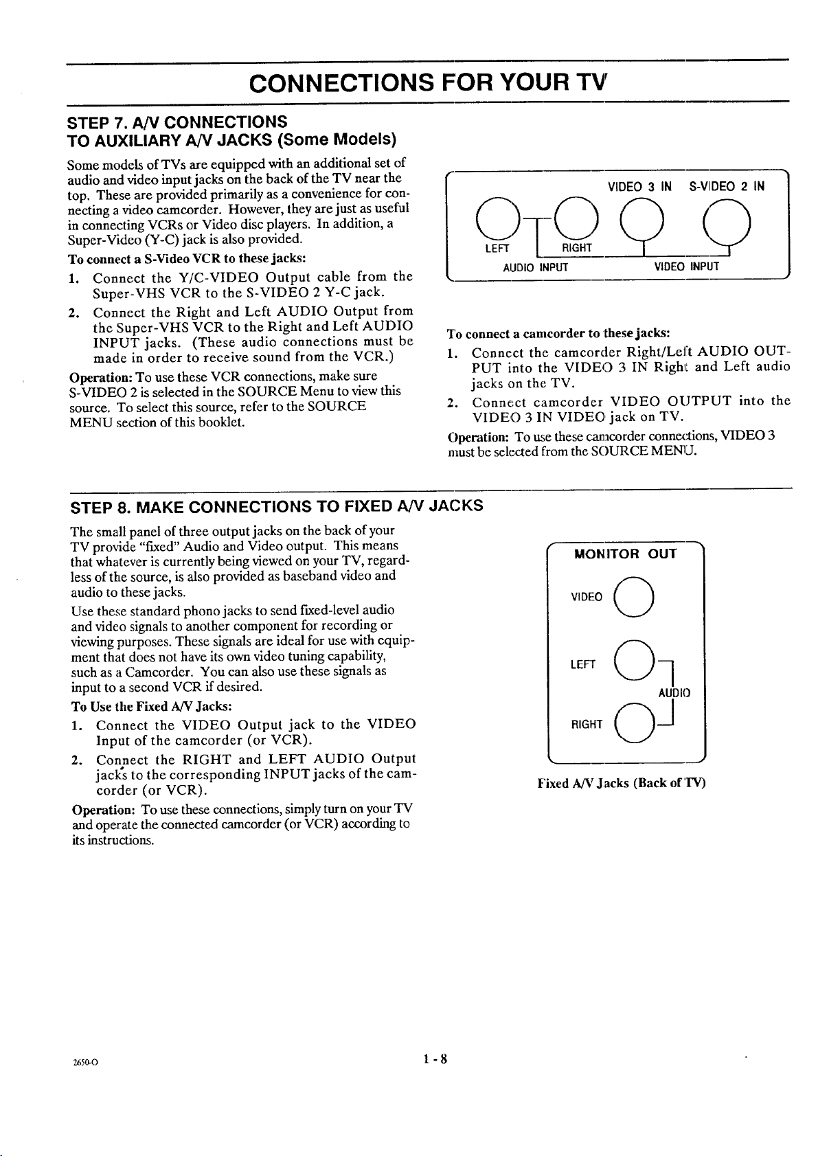
STEP 7. AN CONNECTIONS
TO AUXILIARY AN JACKS (Some Models)
Some models of TVs are equipped with an additional set of
audio and video input jacks on the back of the TV near the
top. These are provided primarily as a convenience for con-
necting a video camcorder. However, they are just as useful
in connecting VCRs or Video disc players. In addition, a
Super-Video (Y-C) jack is also provided.
To connect a S-Video VCR to these jacks:
1. Connect the Y/C-VIDEO Output cable from the
Super-VHS VCR to the S-VIDEO 2 Y-C jack.
2. Connect the Right and Left AUDIO Output from
the Super-VHS VCR to the Right and Left AUDIO
INPUT jacks. (These audio connections must be
made in order to receive sound from the VCR.)
Operation: To use these VCR connections, make sure
S-VIDEO 2 is selected in the SOURCE Menu to view this
source. To select this source, refer to the SOURCE
MENU section of this booklet.
VIDEO 3 IN S-VIDEO 2 IN
AUDIO INPUT
VIDEO INPUT
To connect a camcorder to these jacks:
1. Connect the camcorder Right/Left AUDIO OUT-
PUT into the VIDEO 3 IN Righr_ and Left audio
jacks on the TV.
2. Connect camcorder VIDEO OUTPUT into the
VIDEO 3 IN VIDEO jack on TV.
Operation: To use these c_tnacorder connex_ions, VIDEO 3
must be sele_:ted from the SOURCE MENU.
STEP 8. MAKE CONNECTIONS TO FIXED AN JACKS
The small panel of three output jacks on the back of your
TV provide "fLxed" Audio and Video output. This means
that whatever is currently being viewed on your TV, regard-
less of the source, is also provided as baseband video and
audio to these jacks.
Use these standard phono jacks to send fixed-level audio
and video signals to another component for recording or
viewing purposes. These signals are ideal for use with equip-
ment that does not have its own video tuning capability,
such as a Camcorder. You can also use these signals as
input to a second VCR if desired.
To Use the Fixed A/V Jacks:
1. Connect the VIDEO Output jack to the VIDEO
Input of the camcorder (or VCR).
2. Connect the RIGHT and LEFT AUDIO Output
jack's to the corresponding INPUT jacks of the cam-
corder (or VCR).
Operation: To use these connections, simply turn on your TV
and operate the connected camcorder (or VCR) according to
its instructions.
f
MONITOR OUT
VIDEO
LEFT
Fixed AINrJacks (Back of'INr)
265o-0 1 - 8
Page 13
THE FIRST TIME YOU OPERATE YOUR TV
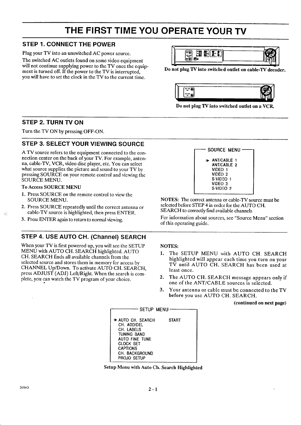
STEP 1. CONNECT THE POWER
Plug your TV into an tmswitched AC power source.
The switched AC outlets found on some video equipment
will not continue supplying power to the TV once the equip-
ment is turned off. If the power to the TV is interrupted,
you will have to set the clock in the TV to the current time.
STEP 2. TURN TV ON
Turn the TV ON by pressing OFF-ON.
STEP 3. SELECT YOUR VIEWING SOURCE
A TV source refers to the equipment connected to the con-
nection center on the back of your TV. For example, anten-
na, cable-TV, VCR, video disc player, etc. You can select
what source supplies the picture and sound to your TV by
pressing SOURCE on your remote control and viewing the
SOURCE MENU.
To Access SOURCE MENU
1. Press SOURCE on the remote control to view the
SOURCE MENU.
2. Press SOURCE repeatedly until the correct antenna or
cable-TV source is highlighted, then press ENTER.
3. Press ENTER again to return to normal viewing.
Do not plug "IV into switched outlet on cable-TV decoder.
Do not plug TV into svAtched outlet on atVCIL
--SOURCE MENU--
->. ANT/CABLE 1
ANTIC;ABLE 2
VIDEO 1
VII')EO 2
S-VIDEO 1
VIDE() 3
S-VIDEO 2
NOTES: The correct antenna or cable-TV sourca._must be
selected before STEP 4 in order for the AUTO CH.
SEARCH to correx's..lyfind available channels
For information about sources, see "Source Menu" section
of this operating guide.
STEP 4. USE AUTO CH. (Channel) SEARCH
When your TV is first powered up, you will see the SETUP
MENU with AUTO CH. SEARCH highlighted. AUTO
CH. SEARCH finds all available channels from the
selected source and stores them in memory for access by
CHANNEL Up/Down. To activate AUTO CH. SEARCH,
press ADJUST (ADJ) Left/Right. When the search is com-
plete, you can watch the TV program of your choice.
SETUP MENU
->-AUTO CH. SEARCH
CH. ADD/DEL
CH. LABELS
TUNING BAND
AUTO FINE TUNE
CLOCK SET
CAPTIONS
CH. BACKGROUND
PROJO SETUP
Setup Menu with Auto Ch. Search Highlighted
NOTES:
1. The SETUP MENU with AUTO CH, SEARCH
highlighted will appear each time you turn on your
TV until AUTO CH. SEARCH has been used at
least once.
2. The AUTO CH. SEARCH message appears only if
one of the ANT/CABLE sources is .,;elected.
3. Your antenna or cable must be connected to the TV
before you use AUTO CH. SEARCH.
(continued on next page)
START
2650-0 2 - I
Page 14
THE FIRST TIME YOU OPERATE YOUR TV
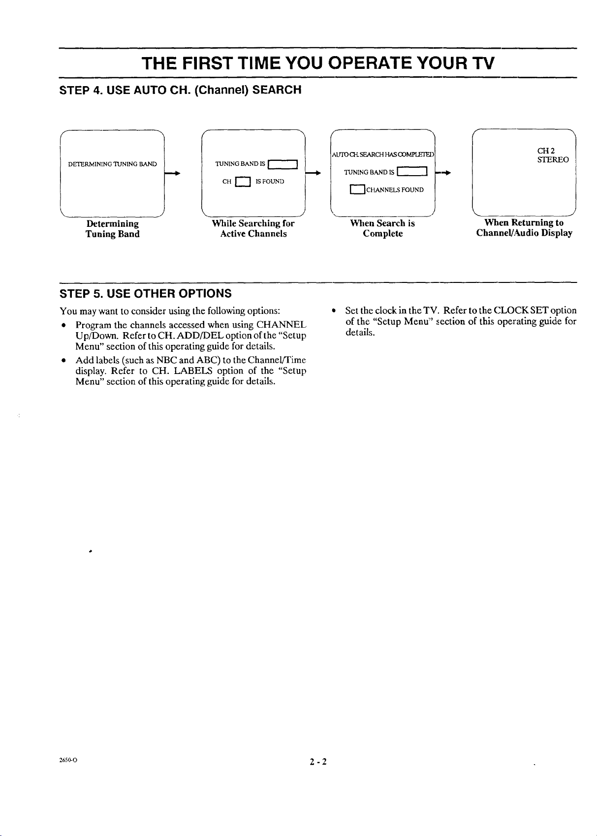
STEP 4. USE AUTO CH. (Channel) SEARCH
AUTO _ SEARCH HAS OOMPI.E!_:
DETERMINING TUNING BAND
TUNING BAND IS
CH I_ 1S FOUND
TUNING BAdqD IS
"--]CHANNELS FOUND
Determining While Searching for When Search is When Returning to
Tuning Band Active Channels Complete Channel/Audio Display
STEP 5. USE OTHER OPTIONS
You may want to consider using the following options:
• Program the channels accessed when using CHANNEL,
Up/Down. Refer to CH. ADD/DEL option of the "Setup
Menu" section of this operating guide for details.
• Add labels (such as NBC and ABC) to the Channel/Time
display. Refer to CH. LABELS option of the "Setup
Menu" section of this operating guide for details.
Set the clock in the TV. Refer to the CLOCK SET option
of the "Setup Menu:" section of this operating guide for
details.
CH2
STEREO
a6s_o 2 - 2
Page 15
OPERATING YOUR TV
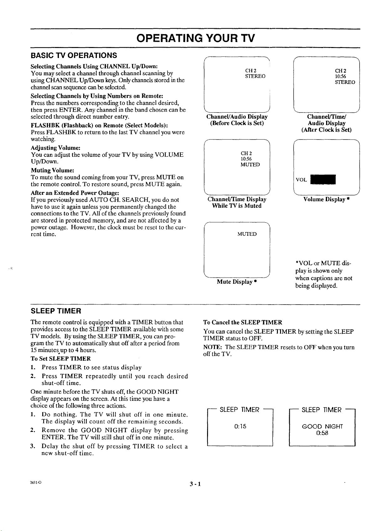
BASIC "IV OPERATIONS .- r
Selecting Channels Using CHANNEL Up/Down:
You may select a channel through channel scanning by
using CHANNEL Up/Down keys. Only channels stored in the
channel scan sequence can be selected.
Selecting Channels by Using Numbers on Remote:
Press the numbers corresponding to the channel desired,
then press ENTER. Any channel in the band chosen can be
selected through direct number entry.
FLASHBK (Flashback) on Remote (Select Models):
Press FI_,A,SHBK to return to the last TV channel you were
watching.
Adjusting Volume:
You can adjust the volume of your TV by using VOLUME
Up/Down.
Muting Volume:
To mute the sound coming from your TV, press MUTE on
the remote control. To restore sound, press MUTE again.
After an Extended Power Outage:
If you previously used AUTO CH. SEARCH, you do not
have to use it again unless you permanently changed the
connections to the TV. All of the channels previously found
are stored in protected memory, and are not affected by a
power outage. However, the clock must be reset to the cur-
rent time.
CH 2
STEREO
Channel/Audio Display
(Before Clock is Set)
CH 2
10:56
MUTED
Channel/Time Display
While TV is Muted
MUTED
CH 2
10.56
STEREO
Channel/Time/
Audio Display
(ARer Clock is Set)
f
I
IVOL
J
Volume Display *
SLEEP TIMER
The remote control is equipped with a TIMER button that
provides access to the SLEEP TIMER available with some
TV models. By using the SLEEP TIMER, you can pro-
gram the TV to automatically shut off after a period from
15 minutesup to 4 hours.
To Set SLEEP TIMER
1. Press TIMER to see status display
2. Press TIMER repeatedly until you reach desired
shut-off time.
One minute before the TV shuts off, the GOOD NIGHT
display appears on the screen. At this time you have a
choice of the following three actions.
1. Do nothing. The TV will shut off in one minute.
The display will count off the remaining seconds.
2.
Remove the GOOD NIGHT display by pressing
ENTER. The TV will still shut off in one minute.
3.
Delay the shut off by pressing TIMER to select a
new shut-off time.
*VOL or MUTE dis-
play is shown only
Mute Display *
To Cancel the SLEEP TIMER
You can cancel the SLEEP TIMER by setting the SLEEP
TIMER status to OFF.
NOTE: The SLEEP TIMER resets to OFF' when you turn
off'the TV.
0:15 GOOD NIGHT
I
when captions are not
being displayed.
0:58
_6sl-o 3 - 1
Page 16
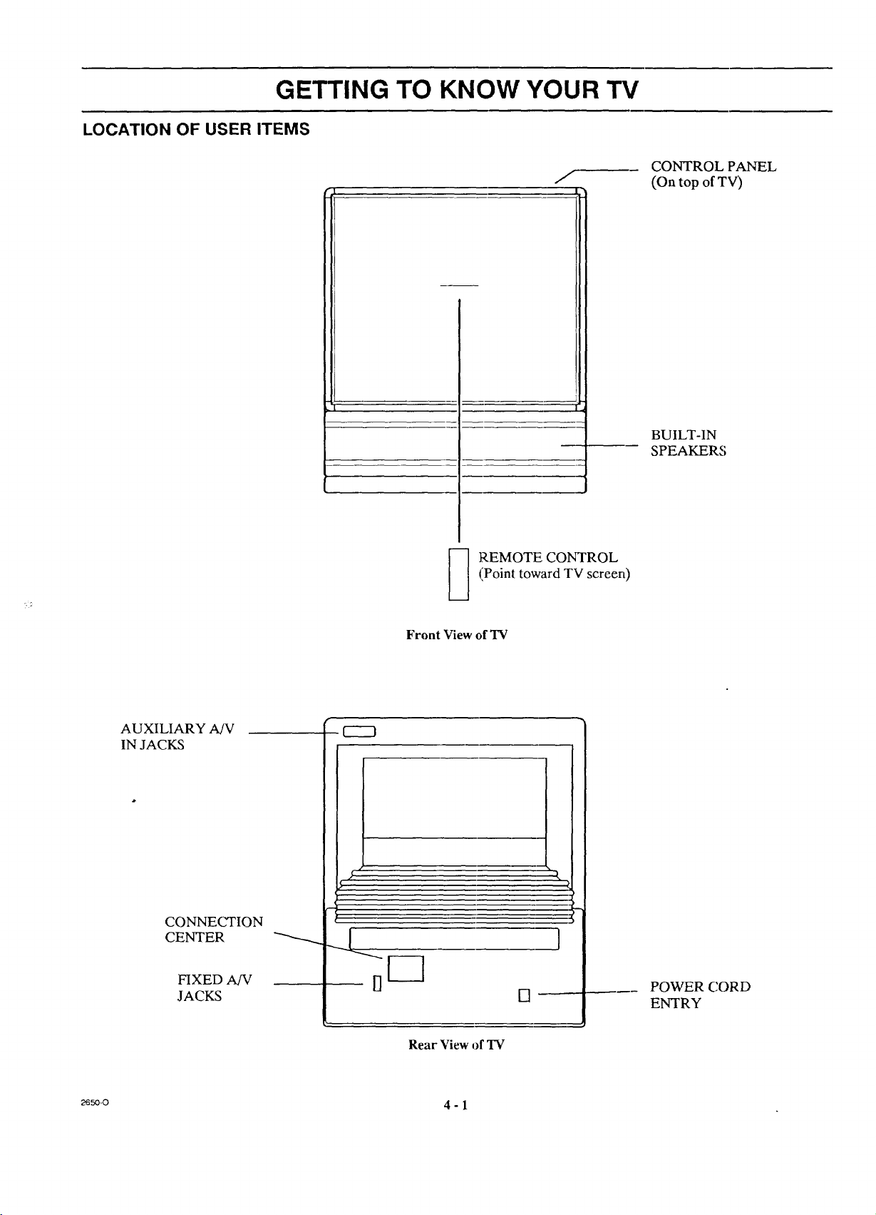
GETTING TO KNOW YOUR TV
LOCATION OF USER ITEMS
I
r_ , , , |
(Point toward TV screen)
_ REMOTE CONTROL
m
CONTROL PANEL
(On top of TV)
BUILT-IN
SPEAKERS
AUXILIARY AfV
IN JACKS
CONNECTION
CENTER
FIXED A/V
JACKS
9----3
Front View of TV
DF-]
Rear View of TV
[]
______ POWER CORD
ENTRY
_so_ 4 - 1
Page 17

GETTING TO KNOW YOUR TV
CONTROL PANEL
Refer to the illustration below while reading the descrip-
tions of the TV controls.
1. ADJUST (ADJ) Left/Right or <--/---_ 5.
Press during on-screen menu operation to see in-
formation/status display for selected option. Press 6.
again to adjust the selected menu option.
2. SELECT or A/V
Press during on-screen menu operations to select a
menu option.
3. MENU
Press once to see a menu. Press repeatedly to se-
quence through the available menus. 7.
4. ENTER
Press to see the Channel/Time display, or to remove
any on-screen display or menu.
VOLUME Up/Down
Press to increase or decrease the :_ound level.
CHANNEL Up/Down
Press to select channels higher or lower than the
channels being viewed. You can also add channels or
delete channels from the scanning sequence stored in
memory. See CH. ADD/DEL option of the "Setup
Menu':' section of lhis operating _;uide for channel
programming information.
OFF-ON
Press to turn TV power ON or OFF.
_o-o 4 - 2
Page 18

OPERATION
REMOTE CONTROL MODEL SC2300
t
For optimum performance, point the
remote control toward your Zenith TV.
'V_JJ IdE: CHANN_
VOLUME Up/Down
Used to adjust the volume level of the TV.
MUTE
Used to turn off sound while the picture
remains. Press again to restore the sound.
INSTALLING BATTERIES
This remote comes with batteries already installed. When it
becomes necessary to replace the batteries, use two (2) high
quality, size AAA, alkaline batteries. Note that batteries
should be replaced when the effective range of the remote
becomes noticeably shorter.
1. Remove the two (2) Phillips head screws from the
back-of the remote and remove the compartment
cover.
,
Remove the old batteries and insert the new bat-
teries making sure the polarity markings (" +" and
"-") on the batteries match those shown in the
compartment.
©
MUTE RF_._ALL
SC2300
NOTES:
• Be careful not to place heavy objects on top of the remote
• If you do not use the remote control for a month or longer,
• Zenith is not responsible for damage caused by such
OFF/ON
Used to turn TV ON or OFF.
CHANNEL Ul_Down
Used to selex:t_.TV channel b,.¢going up or
down through channels.
RECALL (ENTER)
Used to see Channel/Time display for TV
having on-screen displays. Press again to
remove display.
control buttons. Prolonged accidental operation will
shorten battery life.
remove the batteries. Battery leakage can cause damage
to the remote control.
battery leakage.
_) <Rtuovttwosc_,s Toto,tAct _rTtRirs• @
O O
O O
_O 5 - 1
Page 19

OPERATION
REMOTE CONTROL MODEL LR4455
The learning remote supplied with your new Zenith TV al-
lows you to operate most models of infrared (IR) remote-
controlled TVs, VCRs and cable-TV converters, even if
they are all different brands. In addition, it also allows you
to operate other remote-controlled entertainment equip-
ment such as stereo sound systems and video disc players.
In this way, it replaces the many remotes previously re-
quired to operate all of these appliances.
CHOOSE THE OPERATING MODE
To use the remote to operate your TV, VCR, CABLE-TV
converter, or an AUX (auxiliary) device (such as a video
disc player), you must first choose the remote's mode of
operation. 'To select the mode, press the MODE key until
the desired indicator lights.
Point toward unit
to be controlled
Your learning remote is manufactured to operate your
Zenith TV, a Zenith VCR and a Zenith cable-3W con-
verter. It must be "taught" to operate other brands. The
following instructions are for the operation of Zenith equip-
ment. To teach your remote to operate other brands, refer
to "Programming Your Remote Control" later in this book-
let.
Some KEYS; on the remote wiU always operate a particular
appliance. For example, VOLUME always operates the
TV volume and PLAY always operates the VCR. The func-
tion of other keys depends on the mode selected. For ex-
ample, OFF-ON will turn the TV off and on when in TV
mode. If set to VCR mode, this key will turn the VCR off
and on.
Operating mode selection
and indicators
Menu operations on TV
and some VCRs
Numbered buttons for
channel selection and
other uses
Learn functions for user
programmed sequences
NOTE: See following pages
for operating instructions.
_ OFF-ON
[] [] o
SELECT
(KJIT R..A.SE'IBK
CHANNEL
® ® @
VC_E
@ ( )
-CZD CZZ_ CZD CD
LEARN PiP SWAP MUTE
FREEZE MEMORY TIMER SEQ
RECORD STOP PAUSE SEARGH
_ C_ CD
(22_
REW PLAY F FWD TV/VGR
LR4455
Controlled device
OFF/ON
Special features on TV
•and some VCRs
Channel Ul)/Down
for TVs, VCRs and cable
Volume Up/Down for TV
Special features on some
TVs and some VCRs
z6sl-o 6 - 1
Page 20

TV OPERATIONS
REMOTE CONTROL MODEL LR4455
]'he following functions and operations apply to your
Zenith TV. The remote control must be in the TV mode to
operate your TV.
MODE
Press repeatedly to select the TV
mode of operation.
TV
Lights when TV mode of
operation is selected.
CAPTIONS
Used to view closed captions \
broadcast with some television
programs.
MENU, SELECT and ADJUST [
Used with on-screen menus to see ]
menu, select an option, and adjust |
that option. /
Numbered Buttons
Used to select a TV channel.
For optimum performance, point the
remote control toward your TV.
03
SELECT QUIT
© ® ®
6)@@'
® @ @
ENTER
Used to view the Channel/Time Dis-
play or to remove any on-screen
menu or display.
LEARN
Used to program remote.
FREEZE
Used to freeze the motion
picture on the PIP inset.
PIP
Used to activate Picture-In-
Picture inset.
TV Operations
t
LR4455
The VOLUME control will always adjust the TV volume
regardless of the selected operating mode of the remote.
OFF7ON
Used to turn TV ON or OFF.
/
SOIJRCE
Press to display the menu of TV sour-
ces for TVs having a SOURCE Menu,
Press 'SOURCE aga!in to step through
the source selections. On some TVs,
pre:_s 'SOURCE to select the AUX
(At_il.iary) channel.
FLASHBK (Flashback)
Press to return to the last TV channel
you were watching.
CHM_NEL Up/Down
Used to sequence through the TV channels.
Press CHANNEL Up or Down to change
to the next higher or lower channel,
VOLUME Up/Down
Us_ to adjust the volume level of the TV.
MIYIE
Used to turn off sonnd while the pic-
ture remains. Press again to restore
the sound.
SPATIAL EQUALIZATION (SEq)
Used to select SEC! audio mode on
TVs equipped with SEQ feature.
SWAP
U,;ed to swap picture in PIP inset with
the main television picture.
TIMER
Used to activate the SLEEP TIMER.
_svo 6 - 2
Page 21

VCR OPERATIONS
REMOTE CONTROL MODEL LR4455
The follo,_4ng functions and operations apply to Zenith
VCR models built after 1988. The remote control supplied
with your VCR may have keys not duplicated on the new
remote. If these functions are desired, the original remote
control will have to be used.
MODE
Press repeatedly to select the
VCR mode of operation.
VCR
Lights when VCR mode of
operation is selected.
MENU, SELECT, ADJUST
and QUIT
Used with the on-screen menus
and programming options of the
VCR. See VCR operating guide
for details.
Numbered Buttons
Used to select a TV channel
through the VCR. Also, used to
set the timer in the VCR, and to
enter programming information.
For optimum performance, point the
remote control toward your TV.
® @ @
® @ @
For complete: details on how to operate your Zenith VCR,
refer to the operating guide supplied with it,
The remote c_ntrol must be in the VCR mode to operate
your VCR.
t
OFF/ON
j Used to turn VCR ON or OFF.
(__._)
•_ URC[
-3
C
LNREI.
-3
"3
LLIME
FLASHBK (Flashback)
Press during VCR playback to view
the cEannel tuned by the VCR.
CHANNEL Up/Do_a
Used tosequence through channels on
the VCR. Press CH./_qNEL Up or
Down to change to the next higher or
lower channel.
ENTER
Used with the numbered buttons to
select a TV channel through the
VCR.
AM/PM
Used to'set timer during
programming.
RECORD, STOP, PAUSE, SEARCH,
REW, PLAY and F FWD _ VCR Operations
Used for tape recording and playback
functions. See the VCR operating guide
for details.
z6sl-o 6 - 3
@.,,..4 )
CZD
LEARN
CD C:_
MEMORY TIMER
0 C3D (::_D
RECORD STOP Pkt_ SEARCH
(:_) (::_::_ ,_,.-D
RE'W PLAY F FWD TV,"VCR
J
LR4455
TIMER
../ Ac_iv.ates TIME RECORD on
some VCRs.
Z_
0
"I_/VCR
Used to select the source of the
J
programs seen on the TV. Switches
the VCR between TV mode and
VCR mode. "IV Mode: channels are
select ed through the TV. VCR Mode:
channels or tape operation are
select ed through the VCR.
Page 22

REMOTE CONTROL MODEL LR4455
CABLE-TV OPERATIONS
The following functions and operations apply to a Zenith
cable-TV decoder. The remote control supplied with your
cable-TV decoder may have keys not duplicated on the new
remote. Ifthese functions are desired, the original remote con-
trol will have to be used.
For complete information on how to operate your cable-TV
decoder, refer to the operating guide provided with it.
MODE
Press repeatedly to select the
VCR mode of operation.
CABLE
Lights when CABLE mode
of operation is selected. __
MENU, SELECT, ADJUST
and QUIT
Function depends on
cable-TV system.
For optimum performance, point the remote
control toward your cable-TV decoder.
[] @ o
,__LECT OUIT FLASI..I_
© @ @
Numbered Buttons
Used to select channels through
cable-TV decoder.
ENTER
Press after a channel number is entered
to change channel instantly.
@ J ENTER ) [_
CZD O _ CZD
LF_RN PIP SWAP MUTI"
_ CZ_ (ZD CZD
FREEZE MEMORY TIMER SEQ
The remote control must be in the CABLE mode to
operate your cable-TV decoder. The VOLUME control
will always adjust the TV volume regardless of the selected
operating mode of the remote.
t
OFF/ON
Used to tu:rncable-TV decoder
/
/ ON or OF]7.
[] c=:9-
MENU SOURCE
_.IANNH.
SOURCE
Selects "A" or "B" cable channels.
CHANNEl[, Up/Down
Used to seatuence through cable-TV
channels.
VOLUME Up/Down
Used to adjust the volume levelof the TV.
RE-COP,D STOP PAUSE SEARCH
REW RAY F FWD
LR4455
Cable-TV Decoder Opertations
2651-o 6 - 4
Page 23

REMOTE CONTROL MODEL LR4455
PREPARATION FOR USE
Batteries are provided _th this remote, but you must install
them before using the remote.
INSTALLING BATTERIES
When the effective operating range of your remote becomes
noticeably shorter, replace the batteries with two high-
quality, alkaline, size AAA batteries.
NOTE: When the remote does not receive power from its
batteries, it may set itself to Zenith video equipment (TV,
Zenith VCR, and Zenith cable-TV decoder) default codes.
If you have "taught" it to operate other equipment, it will
forget what it was taught.
To decrease this possibility, replace the batteries promptly,
and do not remove the old batteries until you are ready to
insert new ones. The batteries normally have enough power
to save the information even if they do not have enough
power to operate the remote.
°
Remove the battery compartment cover. PUSH
DOWN tab and PULL OUT from top.
2.
Insert new batteries as indicated by the diagram
inside the compartment. Be careful to place the
batteries correctly. If the polarities (the + and -)
are reversed, irreparable damage to the remote
control can occur.
3. Replace the cover by inserting the tab on the bot-
tom of the cover into its housing. Snap the cover
into place.
NOTES:
• Be careful not to place heavy objects on top of the remote
control buttons. Prolonged accidental operation of the
remote control will shorten battery life.
• If you will not use the remote control for a month or more,
remove the batteries. Battery leakage can cause damage
to the remote control.
* Zenith is not responsible for damage caused by such
battery leakage.
lo 1 m
_sl-o 6 - 5
Page 24

REMOTE CONTROL MODEL LR4455
"THREE WAYS TO CUSTOMIZE YOUR REMOTE
'This remote allows you I:ooperate most models of most
]brands of remote-controlled TVs, VCRs and cable-TV
,decoders.
You can operate your equipment with this remote in three
ways:
• By programming brand codes for your equipment.
• By using Auto Find to automatically find the brand codes for
your equipment.
PROGRAMMING BRAND CODES
To program Brand Codes:
1. Find the code that corresponds to each brand and
type of equipment you are going to operate. Refer
to Tables 1, 2 and 3.
For example, if you were programming the remote
for use with a Zenith TV, you would look up
"Zenith" in "Table 1.", and find code "101."
Write the brand codes for your equipment on the
following lines. Keep this operating guide for fu-
ture reference.
TV CODE:
CABLE CODE:
VCRCODE:
2. Press MODE repeatedly to select the desired TV,
VCR or CABLE operating mode for the remote.
• By teaching new functions 1:o specific buttons on the
remote.
If you are using a Zenith TV, Zertith VHS/VCR or a Zenith
cable-TV decoder, it has already been programmed for you.
NOTE: The remote control can only be used to operate
one VCR, one TV and one cable-.TV decoder at a time. If
you program the remote control to operate a TV that is not
a Zenith, it wiJl no longer operate, your Zenith TV.
3. Press LEARN for about 5 seconds until the MODE
indicator lights for the selected TV, VCR or
CABLE mode of operatien.
4. Enter the proper brand code number determined in
Step 1.
5. Press LEARN. All three mode indicators should
light briefly, then turn off to indicate the brand
code has been programmed.
6. If all three mode indicators fail to ]Lightbriefly, an
error has occurred. Repeat Steps 2-5 to try again.
7. Repeat steps 2 - 5 to program the remote for the
other equipment you are using.
NOTE: CABLE mode can be programmed to operate a
second TV or second VCR, if d6sired.
When batteries are removed: It ,hill be necessary to
reprogram the proper VCR and cable-TV decoder codes.
Operating Mode
Indicators I
Numbered Buttons
Used to enter code
number for desired
brand name
VaZl
_ J [_ uENU
[il N
SELECT
® ® ®
® @ @
® @ @
@ ( E.-rE.)
LEARN Button
2651-O 6 - 6
-CZ) CZ) CZZ)
LEARN PtP SWAP
FREEZE U[MOR¥ TIMER
QOIT
O
SOURCE
O
FLASHI_
CHANNEL
VOLUME
MUTE
CZD
SI_Q
/ Ope::ating MODE Selector
Page 25

REMOTE CONTROL MODEL LR4455
TV, VCR AND CABLE-TV OPERATING CODES
Table 1. TV Codes by Brand
'IV Brand
Name
Admiral
Admiral
Akai
Amark
AOC
Bell & Howell
Centurion
Coronado
Curtis Mathes
Curtis Mathes
Curtis Mathes
Daytron
Emerson
Emerson
Emerson
Emerson
Emerson
Emerson
Fisher
Fisher
General Electric
General Electric
General Electric
General Electric
Goldstar
Goldstar
Goldstar
Hitachi
Hitachi
Hitachi
JVC
JVC
J.C. Penney
J.C. Penney
J.C. Penney
J.C. Penney
J.C. Penney
KMC
KTV
KTV
Lodgenet
Logik
LXI
LXI
Magnavox
Magnavox
Magnavox
Magnavox
Magnavox
Magnavox
Majestic
Marantz
Marantz
Memorex
MGA/Mitsubishi 104 'reknika
MGA/Mitsubishi 119 Telerent
MGA/Mitsubishi 120 Telerent
MGA/Mitsubishi 130 Toshiba
Montgomery Ward 103 Toshiba
Montgomery Ward 104 Toshiba
Montgomery Ward 105 Yorx
Montgomery Ward 113 Zenith
Montgomery Ward 114
Code Name Code
TV Brand
116 Montgomery Ward 119
121 Montgomery Ward 121
104 MontgomeryWard 130
103 NEC 104
104 NEC 119
121 Panasonic 106
119 Panasonic 107
103 Philco 103
116 Philco 104
119 Philco 112
121 Philco 113
119 Philips 112
103 Philips 113
104 Pioneer 135
123 Portland 103
124 Quasar 106
131 Quasar 107
136 Realistic 105
109 Realistic 123
118 Realistic 124
106 PCA 104
107 RCA 116
114 PCA 126
116 Sampo 119
103 Samsung 103
104 Samsung 119
119 Samsung 134
102 Sanyo 108
103 Sanyo 109
129 Sanyo 118
125 Scott 119
132 Sears 103
104 Sears 108
110 Sears 109
114 Sears 110
117 Sears 111
119 Sears 118
103 Sears 134
103 Sharp 103
104 Sharp 105
121 Sharp 122
121 Sharp 133
133 Sharp 137
137 Sony 115
103 Sylvania 112
112 Sylvania 113
113 Sylvania 117
119 Sylvania 119
127 Sylvania 127
128 Sylvania 128
121 Tatung 106
104 Teknika 103
120 'Feknika 112
121 'reknika 121
Table 2. VCR Codes by Brand
VCR Brand VCR Brand
Name Code Name Code
Akai 223 Pentax 215
Audio Dynamics 202 Philco 214
Audio Dynamics 218 Philips 214
Broksonic 221 Philips 227
Canon 214 Pioneer 210
Citizen 209 Pioneer 215
Craig 212 Pioneer Laser Disk 228
Curtis Mathes 214 Quasar 214
Curtis Mathes 216 RCA 215
DBX 202 RCA 216
DBX 218 RCA 220
Emerson 203 RCA 227
Emerson 221 Realistic 206
Emerson 223 Realistic 208
Emerson 226 Realistic 212
Emerson 233 Realistic 214
Emerson 235 Realistic 231
Fisher 211 Samsung 220
Fisher 212 Samsung 230
Fisher 213 Sanyo 206
Funai 231 Sanyo 212
General Electric 214 Scott 204
General Electric 216 Scott 205
General Electric 220 Scott 233
Goldstar 209 Sears 206
Hitachi 215 Sears 209
Instant Replay 214 Sears 211
Instant Replay 227 Sears 212
JVC 202 Sears 215
JVC 225 Sharp 208
J.C. Penney 214 SonyVHS 232
J.C. Penney 218 SonyVideo 8 217
J.C. Penney 227 Sylvania 207
Kenwood 202 Sylvania 214
Magnavox 207 Sylvania 227
Magnavox 214 Symphonic 231
Marantz 207 Tashiko 209
Marantz 218 Tatung 202
Marta 209 Teac 202
Memorex 212 Teac 231
Memorex 214 Teknika 234
Memorex 231 Toshiba 205
MGA/Mitsubishi 204 Toshiba 215
MGA/Mitsubishi 222 Vector Research 204
Montgomery Ward 208 Vector Research 218
Montgomery Ward 214 Yamaha 202
MontgomeryWard 219 Yamaha 218
NEC 202 Zenith VHS 201
NEC 218 Zenith VHS 225
Panasonic 214 ZenithVHS 229
124
103
121
110
111
134
119
101
Table 3. Cable Decoder Codes by Brand
Cable Decoder Cable Decoder
Brand Name Code Brand Name Code
Drake Satellite 312 Pioneer 315
Drake Satellite 330 Regency 329
Gemini 305 Samsung 335
Gemini 331 SeientificAtlanta 316
General InstrJment305 Scientific Atlanta 323
General Instrament 306 Scientific Atlanta 336
Hamlin 302 Sprucer
Hamlin 303 (Panasonic) 313
Jerrold 304 Standard
Jerrold 307 Components 335
Jerrold 308 SIS Satellite 324
Jerrold 309 Telecaption 4000 325
Jerrold 310 Toeom 317
Kale Vision 335 Tocom VIP 318
Macom 314 Toshiba 322
Macom 321 Toshiba Satellite 319
Macom Satellite 322 Zenith 301
Magnavox 334 Zenith 322
NSC 335 Zenith AV3000 327
Oak 311 Zenith Satellite 312
Oak 332 25enith Satellite 330
Panasonic 313 Zenith Satellite 328
Panasonic 320 25enith Laser Disk 326
Paragon (zenith) 333
_s,_ 6 - 7
Page 26

REMOTE CONTROL MODEL LR4455
AUTO FIND MODE!
Use Auto Find to automaticaUy fmd the brand code needed
to operate your equipment.
NOTE: If no button is pressed for 60 seconds or more
during Auto Find, the remote wiUautomatically exit Auto
Find without storing any brand codes. (LEDs will flash 3
times upon exiting.)
1. Turn on the equipment you wish the remote to
operate.
2. Press and hold LEARN until mode indicator lights
(about 4 seconds).
3. Use MODE to select the mode you wish to program
(TV, VCR, CABLE or AUX). In the AUX mode
Auto Find will se,arch through all TV, VCR and
Cable brand codes.
4. Enter "00" then press ENTER within 2 seconds. All
four mode indicatoT lights will turn ON and then OFF,
leaving the mode indicator light for the active mode ON.
5. Point remote tow_Lrds the equipment.
_ECIAL PWR ON
EQUIPMENT
Poinf foward
equipmenf
LeQrning
Remofe
6. Press and release OFF/ON on the remote about once
every second, until the equipment turns OFF. Press
ENTER before pressing any other buttons.
If you press OFF/ON again before pressing ENTER
Auto Find will have to be repeated.
7. Try other buttons to see if they operate the equip-
ment. If they do not, you may wish to reenter Auto
Find and try to find another code. The remote will
begin with codes starting from where it left off prior
to exiting Auto Find.
8. Repeat Auto Find for each piece of equipment you
want your remote to operate. NOTE: Only one brand
code can be programmed in each of the four modes.
If no brand code has been entered after searching through
all brand codes in any mode, the ]LEARNING remote will
flash all four mode indicator lights in a chasing manner.
Wait 60 seconds or press ENTEF. or LEARN to return to
normal operation.
ERASE MODE
If you wish to erase learned functions or pro_ammed
brand codes. You may:
A. Re-teach a button.
B. Erase learned functions from all buttons in an
individual mode.
C. Erase learned functions from all buttons and
erase all programmed brand codes.
A. Any button except MODE and LEARN can be re-
taught at any time. See "Learning Mode" section.
B. To Erase Learned Functions from All Buttons in
an Individual Mode
1. Press and hold LEARN until mode indicator
lights (about 4 seconds). The mode indicator
light for the active mo,-le will turn ON.
2. Use MODE to select l:he mode from which all
learned functions are Io be erase, d.
3. Enter one of the following codes to erase all
learned functions in an individual mode:
198 for TV Mode
298 for VCR Mode
398 for CABLE Mode
498 for AUX Mode
Press ENTER within two seconds of the last digit.
NOTE: Any brand codes programmed into the
remote will remain.
4. All four mode indic_Ltor lights will turn on
momentarily to indicate that all learned func-
tions in the selected mode have been erased and
that you have left the Erase mode.
C. To Erase All Learned Functions and All
Programmed Brand Codes
1. Press and hold LEARN until mode indicator
lights (about 4 second.,;).
2. Enter "911" then press ENTER within 2
seconds.
3. All four mode indicaEor lights will turn ON
momentarily to indicate that the remote has left
the Erase mode. All learned functions and all
programmed codes have been erased.
The remote is now programmed with the
default Zenith brand codes as received from
the factory:
101 for TV Mode
201 for VCR Mode
3!31for CABLE Mode
3130for AUX Mode (Satellite)
u_l-o 6 - 8
Page 27

REMOTE CONTROL MODEL LR4455
LEARNING MODE
Your remote can learn new functions - a total of 20 - in 4.
any or all of its four operating modes. You can teach a new
function to any button except MODE and LEARN. 5.
1. Press and hold LEARN until mode indicator lights
(about 4 seconds).
2. Enter "99" then press ENTER on the learning remote
to enter the Learning mode. All four mode indicator
lights will light momentarily. The mode indicator light
for the current mode (TV, VCR, CABLE or AUX) will
then begin flashing.
3. Place the learning and teaching remotes head to
head (on a table or other fiat surface). Press and
hold any button on the TEACHING remote.
The TEACHING remote may have to be moved side-
to-side until the two remotes are aligned properly. The
remotes are aligned properly when the mode indicator
light on the LEARNING remote stops flashing and 7.
remains on continuously. Leave them in this position
until all desired functions have been learned.
Learning
Remote
11r
I
I*---
I
1\1
l\\.
\
I
/
1
_Teaching 1
Remot._______e "--'*1 I
___ _t_k j_ _ i
f, ?___;-
Use MODE on the LEARNING remote to choose
the mode for the equipment you wish i:o operate.
Press the button on the LEARNING remote you
wish to teach. The mode =,indicator light will begin
flashing.
NOTES:
• MODE and LEARN c_anot be taught.
• While the mode indicator fight is. flashing you can
change your mind and choose another button on the
LEARNING remote to be taught or change operat-
ing modes.
6.
Press and HOLD the button on the TEACHING
remote you want the LEARNING remote to learn.
The function has been learned when all mode in-
dicator lights on the LEARNING :remote light up.
Repeat steps 5 and 6 to _each up to 20 functions.
NOTE: If you attempt to teach more than 20 func-
tions, the LEARNING remote will flash all four
mode indicator lights in a chasing manner to indi-
cate that no more butto:as can be taught. You may
now choose to:
a. Use LEARN to exit Learning :mode.
b. Re-teach a button wl_ich has already been taught
by pressing that button.
8. Use LEARN to exit the Learning mode. All four
mode indicator lights will flash three times to indi-
cate you are leaving the Learning :mode.
NOTES
• If no button is pressed for 60 seconds while in Learning
mode, the remote will automatically exit Learning mode
(all four mode indicator lights will flash three times).
• If a new brand code is progxammed in a particular mode
(TV, VCR, CABLE or AUX), all buttons in that mode
which have learned new fun ctions will need to be re-taught
those new functions.
_6__a-o 6 - 9
Page 28

AVAILABLE MENUS
ON-SCREEN MENUS
Your TV is menu operated, that is, adjustments that can be
made to the TV appear on the screen in a list of choices you
can make by using the cor_trols on the front panel of the TV
or on the remote control.
SOURCE MENU
-_ ANT/CABLE 1
ANT/CABLE 2
VIDEO 1
VIDEO 2
S-VIDEO 1
VIDEO 3
.q;-VIDEO 2
AUDIO MENU
BASS - I +
TREBLE - I +
BALANCE L I R
AUDIO STEREO
SEQ ON
SURROUND ==="
NULL - I +
There are four basic menus: SOURCE, SETUP, AUDIO,
and VIDEO. These menus list everything you can adjust to
your personal preference or needs. In addition, separate
SOURCE and VIDEO menus appear for PIP while PIP is
active.
SETUP MENU
÷ AUTOCH.SEARCH
CH.ADD/DEL
CH. LABELS
TUNINGBAND
AUTOFINETUNE
CLOCKSET
CAPTIONS
CH.BACKGROUND
PROJOSETUP
START
I
VIDEO MENU
-_ CONTRAST - = +
BRIGHTNESS - _ +
COLOR - _ +
TINT G I R
SHARPNESS - _ +
COLOR TEMP COOL
VIDEO FILTER OFF
AUTO FLESH ON
PICTURE PREF PRESET
SUMMARY OF MENU ITEMS
SOURCE Menu
Selecting ANT/CABI_,E1 or 2: Either of these sources
may be used for input from an antenna or a cable-TV
line.
Selecting VIDEO 1 or 2: Either of these sources may be
used for input from an auxiliary video source such as a
VCR or.a video disc player.
Selecting S-VIDEO 1: Select this source if a Super-
VHS VCR is connected to your TV.
Selecting VIDEO 3 C$ome models): If your model of
TV is equipped with front A/V jacks, select this source
if a camcorder or other video component is connected
to the front jacks.
Selecting S-VIDEO 2 (Some models): If your model of
TV is equipped with front A/V jacks, select this source
if a Super-VHS VC1;: is connected to the front jacks.
jack to which the input cable or antenna wire is
Make sure the selected source corresponds to the
connected on the b_,ck (or front) of the TV.
SETUP Menu
AUTO CH. SEARCH: Finds all available charmels and
stores them in memory for acce:_s by using CHANNEL
Up/Down.
CH. ADD/DEL: Changes the list of active channels
selected by using CHANNEL Up/Down.
CH. LABELS: Adds a channe], name "LABEL" to the
channel display. For example, ABC may appear when
this network channel is tuned.
TUNING BAND: Determines the operation of the chan-
nel tuner inside the TV.
AUTO FINE TUNE: Lets your TV compensate for varia-
tions in broadcast and cable-TV frequencies.
CLOCK SET: Sets the clock i:athe TV to the correct
time.
CAPTIONS: Displays closed captions (CC) or informa-
tional text when available.
CH. BACKGROUND: Changes the back_ound of the
channel/time display.
(continued on next page)
:_o 7 - 1
Page 29

ON-SCREEN MENUS
SUMMARY OF MENU ITEMS
AUDIO Menu
BASS: Adjusts the BASS (low frequency) level.
TREBLE: Adjust:; the TREBLE (high frequency) level.
BALANCE: Adjusts the BALANCE of sound between
the left and right speakers for stereophonic programs.
AUDIO MODE:/dlows for receiving a Second Audio
Program (SAP), such as a program broadcast with two
audio portions (typically two languages), or lets you
select stereophonic (STEREO) or monaural (MONO)
speaker operation.
SEQ: Turns on an enhanced stereo mode.
SURROUND: Adjusts Surround Sound volume when
used with separately supplied Surround Sound speakers.
NULL: Used to e£nimize front channel sounds from
coming through the surround speakers.
VIDEO Menu
CONTRAST: Adjusts the overall contrast and color
level of the picture.
BRIGHTNESS: Adjusts the brightness level of black
areas in the picture.
COLOR: Adjusts the intensity of the colors in the picture.
TINT: Adjusts the color of the flesh tones.
SHARPNESS: Adjusts the clarity for the clearest picture.
COLOR TEMP: Allows you to change, the "color
temperature" or picture white balance between cooler
natural whites and warmer (red) colors.
VIDEO FILTER: Reduces video "noise" or interference
in dark picture areas resulting in clearer overall pictures.
AUTO FLESH: Automatically maintains natural skin
tones under changing scene and video source conditions.
PICTURE PREF: Lets you decide if you want to use
your own CUSTOM video settings, the factory
PRESET video settings or the THEATER option for
optimum video settings when viewing in low-light condi-
tions.
BASIC MENU OPERATION
-'t
.
To See a Menu or Change a Menu:
Press MENU repeatedly until the desired menu is
shown. Example shows choosing the SETUP Menu.
-- SETUP MENU
-_ AUTO CH. SEARCH
CH. ADD/DEL
CH. LABELS
TUNINGBAND
AUTO FItNETUNE
CLOCK SET
CAPTIONS
CH. BACKGROUND
PROJOSETUP
START
Choosing Setup Menu
2. To Select an Option/Feature on a Menu:
Press SELECT repeatedly until the desired op-
tion/feature is highlighted. The example in the next
column shows selecting TUNING BAND.
3. To Adjust an Option/Feature:
Press ADJUST (ADJ) Left/Right to see and choose
the available options.
AUTO CH. SEARCH
CH. ADD/DEL
CH. LABELS
-_ TUNING BAND
AUTO FINE TUNE
CLOCK SET
CAPTIONS
CH. BACKGROUNEt
PROJO SETUP
4o To Access a Different Main Menu:
Press MENU repeatedly until the desired menu is
shown.
5. To Return to Normal Viewing:
Press ENTER (ENT) c,r wait a few seconds and the
TV will return automat!ically to normal operation.
Service Menus: In addition 1,3the menu:_ shown in this
operating guide, there are menus for factory and field ser-
vicing. Service menus are not intended for use by the owner.
If you inadvertently access a service menu, press ENTER
(ENT) to return immediately to normal "FVviewing.
SETUF MENU
CABLE-CAW
Selecting Tuning Band
265_o 7 - 2
Page 30

SOURCE MENU
SOURCEMENU
ANT/CABLE1
ANT/CABLE2
VIDEO 1
VIDEO 2
S.,VIDEO1
Source Menu
TO SELECT A SOURCE
Purpose
The SOURCE MENU is used to specify the equipment
that is being used to supply the video and audio signals.
You select the source you want by selecting the SOURCE
MENU. It shows the possible sources available for your
viewing selection.
To Access the SOURCE ]MENU Directly
1, Press SOURCE on the remote control to bring up the
SOURCE MENU.
2. Press SOURCE repeatedly until the source you want is
highlighted.
3. Press ENTER to retu:rn to normal viewing.
I'o Access the SOURCE MENU Indirectly
1. Press MENU until the SOURCE Menu is displayed.
2. Press SELECT Up/Down until the desired source is
highlighted.
3. Press ENTER to return to normal viewing.
Source Identification
The Channel/Time display is used to determine the type of
input source currently being viewed. To see the Channel!
Time display, press ENTER. If an antenna or cable-TV
_,x)urceis being viewed, the Channel/Time display is shown in
the Channel Number/Time format. If a Video source is being
_fiewed, the Channel!Time display is shown in the Video/Time
format.
]NOTE: The sources arc: identified by color in both the on-
screen displays and on the connection center on the back of
the TV. The color for the Channel/Time display, Volume
and Muted display will match the color or the source you
are watching. The color will also help to identify which
source you are watching when viewing PIP. The colors are
as follows:
SOURCE MEIqU
ANT/CABLE1
ANT/CABLE2
VIDEO 1
VIDEO 2
S-VIDEO 1
VIDEO 3
S-VIDEO 2
Source Menu for "INs with Auxiliary ,Jacks
SOURCE COLOR
ANT/CABLE 1 ........................ RED
ANT/CABLE 2 ........................ BLUE
VIDEO 1 ............................. MAGENTA
VIDEO 2 ............................. LT. BLUE
S-VIDEO 1 ........................... GREEN
VIDEO 3 ............................ YELLOW
S-VIDEO 2 ........................... WHITE,
Source Equipment Connections
The actual source selected for viewing on your TV depends
on how the TV is connected to external equipment.
Selecting ANT/CABLE 1 or 2 from SOURCE Menu:
Routes the ANTENNA or cable-TV source to the TV for
viewing. You see program materi_d from whichever signal
source is connected to the ANT/CABLE jack. Usually the
antenna is connected to the ANTENNA jack. In cable ap-
plications, the output from a cable-TV decoder i,; con-
nected to this jack. For VCR application, the Ab,_ OUT
from the VCR is connected to this jack.
Selecting VIDEO 1 or 2 from SOURCE Menu:: Routes the
auxiliary video source (such as a VCR or a Video Disc
player) to the TV for viewing. The video source must be
connected to the corresponding VIDEO 1/2 jacks.
Selecting S-VIDEO 1: Routes the auxiliary Super-VHS
VCR Source to the TV for viewing. The Super-VHS VCR
must be connected to the corresponding input jacks.
Selecting VIDEO 3 from SOURCE Menu: Routes the
auxiliary video source (such as a camcorder, VCR or a
Video Disc player) to the TV for viewing. The video source
must be connected to the corresponding VIDEO 3 jacks.
Selecting S-VIDEO 2: Routes the auxiliary Super-VHS
VCR source to the TV for viewirg. The Super-vi-IS VCR
must be connected to the corresponding S-VIDEO 2jacks.
z651_ 8 - 1
Page 31

SI::TUPMI-NU
SETUP MENU
-_ AUTO CH. SEARCH
CH, ADDIDEL
CH, LABELS
TUNING I_,ND
AUTO FINE TUNE
CLOCKSET
CAPTION:_
CH, BACKGROUND
PROJO _;ETUP
START
!Main Setup Menu
AUTO CH. (Channel) SEARCH
Purpose
Finds all available channels and stores them in memory for
access by CHANNEL Up/Down.
Use AUTO CH. SEARCH only when you first install your
TV, or when you permanently change the connections to
the TV. For example, when you replace the antenna with a
cable-TV system.
Before Using AUTO SEARCH
Connect and turn ON all external equipment, such as a
cable-TV decoder, VCR, etc.
NOTE: AUTO CH. SEARCH can only be used with ANT/
CABLE i or 2 source selection.
To Use AUTO SEARCH
1. AUTO CH. SEARCH should be selected if you
followed the "Basic Menu Operation" given in thc
"On-Screen Menu" section.
.
Press ADJUST (ADJ) Left/Right to start the
AUTO CH. SEARCH. The status of the search is
shown in the display. When the search is complete,
you can watch the TV program of your choice.
SETUP MENU
SETUP MENU
-> CLOCK SET
CAPTIONS
CH. BACKGROUND
PROJO SE'rUP
..:--
Setup Menu for Videe and S-Video Sources
3. Use the AUTO CH. SEARCH feature inde-
pendently for each ANTENNA or CABLE signal
source connected to your TV. Select one source by
using the SOURCE MENU (ANT/CABLE 1 or 2)
and use AUTO CH. SEARCH. When completed,
select the other source and use AUTO CH.
SEARCH again.
When Some Channels Are Not Found
AUTO CH. SEARCH finds c nly active channels and stores
them in its channel memory. You can add channels to those
stored in memory by using the CH. ADD/DEL option.
If you have difficulty tuning some channels, you may have to
manually change the BAND SELECT and AUTO FINE
TUNE mode. Refer to respective option for details.
NOTE: If the output from a cable box is the input to your
TV, the only active channel will be either 3 or 4.
-->AUTO CH. SEARCH
CH. ADD/DEL
CH. LABELS
TUNING BAND
AUTO FINE TUNE
CLOCKSET
CAPTIONS
CH. BACKGROUND
PROJOSETUP
Selecting Auto Ch. Search
DETERMINING TUNING BAND
Determining
Tuning Band
,_so-o 9 - 1
TUNING BAND IS
CH [--'1 IS FOUND
While Searching for
Active Channels
START
S
AUTO CH. SEARCH HAS COMPLETEI2
TUNING BAND IS
[_CHANNELS FOUND
When Search is
Complete
CH 2
STEREO
J
When Returning to
Channel/Audio Display
Page 32

SETUP MENU
CH. (Channel) ADD/DEL
Purpose
Lets you add channels to and remove channels from the ac-
tive channels found by the AUTO CH. SEARCH option. In
this way, you can customize the channels that are accessed
tlu'ough CHANNEL Up/Down.
Ctt. ADD/DEL is an optional feature. You do not have to
activate this feature in order to use your TV.
Before Using CH. ADD/DEL
Use the AUTO CH. SEARCH feature, if not previously
used when you first installed the TV.
NOTE: CH. ADD/DEL can only be used with ANT/
CABLE 1 or 2 Source selection.
SETUP MENU
AUTO CH. SEARCH
•-_ CH. ADD/DEL
CH. LABELS
TUNING BAND
AUTO FINE TUNE
CLOCK SET
CAPTIONS
CH. BACKGROUND
PROJO SETUP
Selecting Ch. Add/Del
CH 13 ADD
To
Add a Channel to Scan Sequence
1.
CH. ADD/DEL should be selected if you followed
the "Basic: Menu Operation" given in the "On-
Screen Menu" section.
2. Use the numbered buttons to access channels not
presently stored in the channel scan sequence.
3. Add channel by pressilag ADJUST (ADJ)
Left/Right until the display shows ADD.
4. Press ENTER to return to normal TV viewing.
To Delete a Channel from Scan Sequence
1. CH. ADD/DEL should be selected if you followed
the "Basic Menu Operation" given in the "On-
Screen Menu" section.
2. Using CHANNEL(CH) Up/Down go to the chan-
nel you wish to remove.
3. Remove channel by pressing ADJUST (ADJ)
Left/Right until the display shows DEL.
4. Press ENTER to return to normal TV viewing.
When Some Channels Can Not Be Tuned
If you have difficulty tuning some channels, you may have to
manually set the TUNING BAND option. If you have the
correct band, but are still having difficulty finding a channel
you know to be active, set the AUTO FINE TLINE to
SEARCH.
CH. (Channel) LABELS
lh]rpose
This option allows you to show a channel "name" each time
the Channel/Time display appears on the TV. In other
words, if you choose the label "ABC" for channel 13,
"ABC" appears in the Channel/Time display. Therefore,
you always know what channel you are watching.
The labels shown in the following table may be "assigned"
to channels.
NOTES:
• CH. LABELS is not displayed when an auxiliary video
source (Video 1, 2 or S-Video 1) is being used.
• These labels are in the memory of the TV. You can not
make your own labels.
• To remove an assigned channel label, select the one that
is "blank."
SI-TUP MENU
AUTO CH. SEARCH
CH. ADD/DEL
-->CH. LABELS
TUNING BAND
AUTO FINE TUNE
CLOCK SET
CAPTIONS
CH. BACKGROUND
PROJO SETUP
CH 13 ABC
A&E ABC
BRAV CA
CNBC CNN
DIS DISC
EWTN FAM
HN ttSE
MAX MEU
NOS PBS
SC SltOW
TMC TNN
USA VC
WGN WTBS
ACTS ADC AMC BET
CBC CBN CBS CMTV
COM CA;PN C'rN CTV
E 1. ENC ESPN
FNN FOX GALA HBO
HSN ]C INSP LIFE
MMT MTV NI3C NICK
PLAY I'lL QVC REQ
SIN "JIBS TBN TLC
TNT TRAV TSN TWN
VCR "vH1 VISN VJN
WWOR YTV
To Use CH. LABELS
1.
CH. LABELS should be selected if you followed
the "Basic Menu Operation" given in the "On-
Screen Menu" section.
2. Using the number buttons or CHANNEL Up/
Down, select a channel.
3. Press ADJUST (ADJ) Left/Right to sequence
through the available choices until the. desired label
appears.
4. Press ENTER to return to normal TV viewing.
Selecting Ch. Labels
z6:_o 9 - 2
Page 33

TUNING BAND
SETUP MENU
Purpose
Allows for setting the TV tuner to match your antenna or
cable-TV system.
If you used the AUTO CH. SEARCH feature, the proper
BAND was set automatically for your TV. If you did not use
AUTO CH. SEARCH, or you are having difficulty tuning
channels, the TUNING BAND may have to be set manually
to match your viewing needs.
Before Using TUNII_G BAND
Connect and turn ON all external equipment, such as a
cable-TV decoder, VCR, etc. Use AUTO CH. SEARCH,
if not previously used.
NOTE: TUNING BAND can only be used with ANT/
CABLE 1 or 2 Source selection.
To Use TUNING BAND
1. TUNING BAND should be selected if you followed
the "Basic Menu Operation" given in the "On-
Screen Menu" section.
SETUP MENU
AUTO CH. SEARCH
CH. ADD/DEL
CH. LASELS
TUNING BAND
AUTO FINE TUNE
CLOCK SET
CAPTIONS
CH. BA(,KGROUND
PROJOSETUP
Selecting Tuning Band
CABLE-CAW
2. Press ADJUST (ADJ) Left/Right to select the
desired tuning band, as shown below:
• BROADCAST is used for standard over-the-air
broadcasts.
• Cable - CATV is used for most standard cable-TV
(CATV) systems.
• Cable - HRC is used for cable-'l?V systems that use
HRC (Harmonically Related Carrier).
• Cable - ICC is used f.ar cable-TV systems using ICC
(Incremental CohererLt Carrier).
Available Channels per Band
The channels that are available in the broadcast and cable
tuning bands are shown below:
BROADCAST Band
VHF 2 to 13 UHF 14 to 69*
* Channels above 69 are not selectable.
CATV, HRC and ICC Bands
I to 125"*
** Channels above 125 are not selectable.
When Some Channels Are Not Clear
If some channels are not clear, change the AUTO FINE
TUNE. You may have to try 6ifferent TUNING BAND and
AUTO FINE TUNE combinations until you get a clear pic-
ture, channel-to-channel. Refer to the AUTO FINE TUNE
option for details.
AUTO FINE TUNE
Purpose
Lets your TV compensate for variations in broadcast and
cable-TV frequencies.
If you are having difficulty tuning channels, the AUTO
FINE TUNE may have to be set manually to match your
viewing needs.
Before Using AUTO, FINE TUNE
Connect and turn ON all external equipment, such as cable-
TV decoder, VCR, etc.
SETUP MENU
AUTO CH. SEARCH
CH. ADD/DEL
CH. LABELS
TUNING BAND
-> AUTO FINE TUNE
CLOCK SET
CAPTIONS
CH. BACKGROUND
PROJO SETUP
FIXED
Selecting Auto Fine Tune
NOTE: AUTO FINE TUNE can only be used with ANT/
CABLE i or 2 Source selection.
To Use AlYrO FINE TUNE
1. AUTO FINE TUNE should be selected if you fol-
lowed the "Basic Menu Operation" given in the
"On-Screen Menu" section.
2. Pres,; ADJUST (ADJ) Left/Right to select the
desired mode of operation, as follows.
• FIXED is used to receive "over-I:he-air" TV stations,
and with many cable-TV system,;.
• SEARCH is used only when the TV must search to
find the frequency being received, such as when used
with certain VCRs and video game controllers.
When Some Channels Are Not Clear
If some channels are not clear, change the TUNING
BAND. You may have to try different AUTO FINE TUNE
and TUNING BAND settings until you get a consistently
clear picture, channel-to-chaanel. Refer to the TUNING
BAND option for details.
26s0-o 9 - 3
Page 34

SETUP MENU
CLOCK SET
Purpose
Sets the clock in the TV to the correct time. After the time
is set, the current time will appear on the Channel!Time dis-
play whenever the TV is turned on, the channel is changed,
or ENTER is pressed.
Power Failure Note: The time will have to be reset if power
to the TV is interrupted.
SI-TUP MENU
AUTO CH. SEARCH
CH. ADD/DEL
CH. LABELS
TUNING BAND
AUTO FINE TUNE
CLOCK SET
CAPTIONS
CH. BACKGROUND
PROJO SETUP
Selecting Clock Set
CAPTIONS
10:30
To Use CLOCK SET from Remote Control
1. CLOCK SET should be selected if you followed the
"Basic Menu Operation" given in the "On-Screen
Menu" section.
2. Use the numbered buttons on the remote control to
enter the current time. Press ENTER to start the
clock.
For example, to set the clock to 10:30, press 1, then
0, then 3, then 0; and then press ENTER. If you
enter an invalid time, such as 14:35 or 2:8(I, the time
will disappear and you can enter another time.
To Use CLOCK SET from Control Panel
1. Use SELECT Up/Down to highlight CLOCK SET
in the SETUP MENU.
2. Use ADJ Left/Right to set the time, and then press
ENTER to start the clock.
F_urpose
Displays closed captions (CC) or informational text when
available on the selected channel.
1'o Access CAPTIONS Indirectly
1. CAPTIONS should be selected if you followed the
"Basic Menu Operation" given in the "On-Screen
Menu" section.
2. One of five different selections is shown: OFF,
CAPTION 1, CAPTION 2, TEXT 1, and TEXT 2.
3;. Press ADJUST (ADJ) Left/Right to select desired
mode of operation.
4. The display disappears from the screen automat-
ically in about 10 seconds, or you may press ENTER
(ENT) to remove the display immediately.
SETUP MENU
AUTOCH. SEARCH
CH.ADD/DEL
CH.LABELS
TUNINGBAND
AUTOFINETUNE
CLOCKSET
_- CAPTIONS
CAPTION 1
CH.BACKGROUND
PROJOSETUP
Selecting Captions
To Access CAPTIONS Directly
1. Press CC-QUIT on the remote control to select
CAPTIONS. One of the five different selections is
shown: OFF, CAPTION 1. CAPTION 2, TEXT 1,
and TEXT 2.
2. Press ADJUST (ADJ) Left/Right to select the
desired status.
3. The display disappears from the screen automat-
ically in about 10 seconds, or you may press ENTER
(ENT) to remove the display immediately.
Application
Your new TV is able to decode and display tlhe Closed cap-
tions and informational text that are broadcast with some
TV shows. Captions can be subtitles for the hearing im-
paired, or translations into another language. Informational
text can be the daily program schedule for the TV station,
or special announcements.
Look for a (CC) or similar sign in your TV schedule, or on
the video tape: cassette, which indicates that captions are
provided.
The closed caption signal is recorded by all VCRs when
recording a TV broadcast or copying a tape having closed
captions.
(continued on next page)
_so_o 9 - 4
Page 35

SETUP MENU
CAPTIONS
About Closed Caption Operation
Once you turn CAPTIONS ON, they will stay ON until you
turn CAPTIONS OFF. Captions will appear as they are
received. If captions stop being received, they will stop ap-
pearing on the TV. If they are received again, captions will
automatically appear again on the TV. The captions will ap-
pear on the TV as they were created. If they were created
in color, they will appear in color. If they were created in
both upper and lower case letters, they will appear inboth
upper and lower case letters.
Hello! Are you
there?
J
Typical Captions Display
The TV can not show more than one on-screen display at a
time, so no captions wiJtlappear until all other displays have
been removed from the screen.
To remove a display that is interfering with captions, press
ENTER until the display disappears. Likewise, you can in-
stantly remove any captions by pressing ENTER to call up
the Channel/Time display. When you press ENTER again,
f
r ..................
See special
newscast tonight
at 7:00PM on
channel 2.
the Channel/Time display disappears and you return to cap-
tions.
CAPTIONS has four different selections that can be made:
t ............. _ ....
_Typical Text Display _
CAPTION 1, CAPTION 2, TEXT 1 or TEXT 2. At the
time of this writing, ve_y little appears in any selection ex-
cept CAPTION 1. Therefore, you should select CAPTION
i and leave it in that position unless you know there is some-
thing you want to see in one of the other selections. Once
you make a selection, that selection is remembered until
you change it.
:':':r
CH. BACKGROUND
Purpose
When you turn on your TV, the Channel!Time display show
the current channel, time (if set) and type of audio signal
(STEREO, MONO or 2ND AUDIO/SAP). The CH.
BACKGROUND feature allows you to show the numbers
and letters on a small colored field which serves as the back-
ground. NOTE: This background will then also appear on
the Mute display as well.
2,
One of two different selections i,; shown: ON or
OFF.
3.
Press ,ADJUST (ADJ) Left/Right to select the
desired status.
4.
The display disappears from the :screen automat-
ically in about 10 second,;, or you may press ENTER
(ENT) to remove the display immediately.
To Operate CH. BACKGROUND
1. CH.BACKGROUND should be selected if you fol-
lowed the "Basic Menu Operation" given in the
"On-Screen Menu" section.
Caption may be shown
anywhere on the screen.
(Shown here at bottom
of screen.)
Fixed size text window.
May be _dlblack when no
information is shown.
SETUP MENU
AUTO CH, SEARCH
CH. ADD/13EL
CH. LABELS
TUNING BAND
AUTO FINE TUNE
CLOCKSE'i"
CAPTIONS
-_ CH. BACKGROUND
PROJO SETUP
Selecting Ch. Background
ON
_5_o 9 - 5
Page 36

SETUP MENU
PROJO (Projection) SETUP
Purpose
Lets you verify and adjust, if needed, the dynamic color con-
vergence of the TV.
Your projection TV has three separate projection picture
tubes, one for each primary color: red, green and blue. To
obtain a good color pictm;e, it is necessary that all three
colors are aligned exactly. This alignment is called "conver-
gence."
Your TV was properly converged at the factory. However,
in.some cases, the convergence may be affected depending
on where you place the TV.
If you move your TV from its original location, or if after
time, you notice color "fringes" in the picture, you may want
to realign the colors by adjusting the convergence as
described in the following steps.
B_eforeUsing PROJO SETUP
1. Place the TV in its permanent location.
2. Turn the TV on and select an active channel. Let
the TV warm up for a few minutes.
SETUP MENU
If the display appears as fou_:white right-angle lines
as shown at the right, no adjustment is necessary.
If there are more than four lines, each a different
color, you must adjust the convergence.
,
Use the SELECT and ADJUST arrow keys (Up,
Down, Left and Right) to adjust the Red lines until
they are on top of the Green lines.
4.
Use MENU to change the test color to Blue.
5.
Use the SELECT and ADJUST arrow keys (Up,
Down, Left and Right) to adjust the Blue lines until
they are on top of the other lines. All lines should
now be white.
6. Press ENTER to return to normal viewing.
NOTES:
• While the Blue test color is Sl_LOWing,the following mes-
sage appears at the bottom of '_Lhescreen.
PRESS ARROW KEYS TO CONVERGE BLUE
• While the Red test color is showing, the following message
appears at the bottom of the screen.
PRESS ARROW KEYS TC, CONVERGE RED
AUTO CH. SEARCH
CH. ADD/DEI.
CH. LABELS
TUNING BAI_D
AUTO FINE TUNE
CLOCK SET
CAPTIONS
CH. BACKGROUND
")" PROJO SETUP TO CONVERGE
Selecting Projo Setup
To Use PROJO SETUP
1. PROJO SETUP slhould be selected if you followed
the "Basic Menu Operation" given in the "On-
Screen Menu" section.
2. With PROJO SETUP highlighted, press ADJ (Ad-
just) lzeft/Right to view the convergence lines.
Good Convergence
SETUP MENU WITH AUXILIARY VIDEO SOURCE SELECTED
If one of the auxiliary video sources (VIDEO 1, VIDEO 2,
VIDEO 3, S-VIDEO 1 or S-VIDEO 2) is selected for your
main viewing picture, many of the SETUP MENU options
will not appear when the SETUP MENU is accessed. The
illustration below show.,; the SETUP MENU as it would ap-
pear. Only the CLOCK SET, CAPTIONS, CH. BACK-
GROUND and PROJO SETUP options remain. Refer to
the earlier discussions when setting these options.
-_ CLOCK SET
Setup Menu for Video and S-Video Sources
[
1I
Bad Convergence
SETUP MENU
CAPTIONS
CH. BACKGROUND
PROJOSETUP
_so-o 9 - 6
Page 37

GENERAL INFORMATION
AUDIO MENU
AUDIO MENU
* BASS - I +
TREBLE - I +
BALANCE L I R
AUDIO STEREO
SEQ ON
SURROUND Bm
NULL - I ÷
NOTE: All adjustments on the
AUDI(3 MENU are optional. You
do not have to use these features in
order to use your TV.
Your TV is equipped to receive Multi-channel Television
Sound (MTS) when available in your area. It can also
receive a Second Audio Program (SAP), that is, a program
broadcast with two attdio portions (two languages). The fol-
lowing modes of operation are available.
STEREO
Directs the sound to the left and right speakers as supplied
by the program source (broadcast TV station, VCR, etc.)
MONO (Monaural)
Directs the same sound to both left and right speakers even
if the source being received is in stereo.
2ND AUDIO/SAP (Second Audio Program)
Directs the sound for the (SAP) Second Audio Program
(typically a second language) to both the left and right
speakers. SAP sound is always monaural.
Dolby Surround Sound
Dolby Surround Sound gives the effect of surrounding you
in sound while listening to your TV. Optional surround
speakers are connected to the TV's rear connection panel
as shown on page 1-7.
Surround Sound is "hidden" in the left and right channels
of a stereo signal. Therefore, raonaural broadcasts and
tapes of monaural programs can not provide Surround
Sound. However, many video tapes, laser discs, premium
cable channels and MTS stereo television,; broadcasts fea-
ture Dolby Surround encoding. Look for the following logo
to identify these.
NOTE: Dolby Surround Sound can be enabled only if
stereo has been previously sek:cted by using the AUDIO op-
tion and the signal being received is stereophonic.
Automatic Mode Selection
We recommend that you use tire STEREO option. The TV
will switch automatically between the STEREO and
MONO modes dependent on the signal being received.
If you prefer SAP, use the 2ND AUDIO/SAP option. On
those stations which broadcast: two audio portions, you will
hear the SAP (usually a seconcl language). When the SAP
broadcast ends, the TV switches automatically between
STEREO and MONO modes. The TV switches back to
2ND AUDIO when the SAP broadcast resumes.
BASS-
Use ADJUST (ADJ) Left/Right to adjust the amount of
BASS (low-frequency level) in the sound. To decrease (-)
BASS, press ADJUST (ADJ) Left. To increase (+) BASS,
press ADJUST (ADJ) Right.
TREBLE
Use ADJUST (ADJ) LeftfRight to adjust the amount of
TREBLE (high-frequency level) in the sound. To decrease
(-) TREBLE, press ADJUST (ADJ) Left. To increase
( + ) TREBLE, press ADJUST (ADJ) Right.
2ro_ 10 - 1
BALANCE
Use ADJUST (ADJ) Left/Ril;ht to shift the BALANCE of
sound between the left and right speakers as indicated by
the on-screen display. To increase the relative sound level
in the Left (L) speaker, press ADJUST (ADJ) Left. To in-
crease the relative sound level in the Right (R) speaker,
press ADJUST (ADJ) Right.
Page 38

AUDIO MENU
AUDIO
U,;e ADJUST (ADJ) Left/Right to select the speaker audio
output mode. You may choose either STEREO, MONO or
2ND AUDIO/SAP. If STEREO is selected but not
received, the following line appears at the bottom of the
m_nu"
THIS PROGRAM IS NOT IN STEREO
If 2ND AUDIO/SAP is selected but not received, the fol-
lowing line appears at the bottom of the menu:
THIS PROGRANI HAS NO 2ND AUDIO
In either of these cases, the Channel!Time display will al-
ways show what type of AUDIO signal is being received
and has been selected default.
If you choose STEREO, you may want to enable Dolby Sur-
round Sound by using the SURROUND option.
NOTE: AUDIO mode selection is only available when one
of the ANT/CABLE sources is selected for main picture
viewing.
SEQ (Spatial Equalization)
Use ADJUST (ADJ) Let_Right to turn SEQ ON or OFF.
S]EQ improves tonal balance and increases apparent stereo
separation to produce a spacious and more natural sound.
Music and sounds appear to emanate from points outside
the television set, while dialogue is localized within the pic-
ture.
SEQ is only available if a stereo signal isbeing received and
you have previously selected STEREO using the AUDIO
option or if STEREO is selected by default.
If no stereo signal is being received, the words NOT
AVAILABLE appear next to SEQ, and the following line
appears at the bottom of the menu:
THIS PROGRAM IS NOT IN STEREO
If your AUDIO selection is either MONO or 2ND
AUDIO/SAP, the words NOT AVAILABLE appear next
to SEQ and one of the following lines appear at the bottom
of the menu:
MONO HAS BEEN SELECTED
2ND AUDIO HAS BEEN SELECTED
Some weak or nonstandard signals may not be suitable for
SEQ, which may make kaperfections in the audio transmis-
sion more obvious. Turn SEQ off if this condition exists.
NOTE: If SEQ is available, you can turn SEQ ON or OFF
directly by pressing SEQ on the remote control.
SURROUND
Use ADJUST (ADJ) Left/Right to adjust the level of Dolby
Surround Sound you wish to obtain. To decrease (-)
Dolby Surround Sound, press ADJUST (ADJ) Left. To in-
crease (+) it, press ADJUST (ADJ) Right.
Dolby Surround Sound is only available if a stereo signal is
being received and you have previously selected STEREO
using the AUDIO option or if STEREO is selected by
default.
When SURROUND is activated, "SURROUND
SPEAKERS REQUIRED" appears at the bottom of the
menu. This is a reminder that Dolby Surround Sound is
only available when you have optio_aal surround speakers
connected to the SURROUND SPEAKER jack. The TV's
internal speakers do not produce s arround sound.
If no stereo signal is being received, the words NOT
AVAILABLE appear next to SURROUND, and the fol-
lowing line appears at the bottom of the menu:
THIS PROGRAM IS NOT IN STEREO
If your AUDIO selection is either MONO or 2ND
AUDIO/SAP, the words NOT AVAILABLE appear next
to SURROUND and one of the following lines appear at
the bottom of the menu:
MONO HAS BEEN SELECTED
2ND AUDIO HAS BEEN SELECFED
NULL
The NULL adjustment is used to minimize front channel
sound from coming through the surround speakers and to
optimize surround decoder performance. To properly set
the NULL adjustment:
1. Play a DOLBY SURROUND encoded video tape
which contains dialogue.
2. Make sure theTVAUDIO mode is set to STEREO
and the SURROUND wglume is turned tip.
3. Select the NULL option. While viewing a portion
of the tape which contains both music and dialogue,
use ADJUST to adjust the NULL so that the
dialogue is barely heard from the surround
speakers.
4. Press ENTER to return tc normal television view-
ing.
NOTES
1. Continuously pressing ADJ Left in the surround
level menu will automatically turn Surround
speakers OFF.
2. If the current program is not in stereo, you will not
be able to change the SURROUND option. The
status display shows "THIS PROGRAM IS NOT IN
STERE()."
3. If you are in the SURROUND menu option and
press MUTE on the remote control, only the Sur-
round speakers are muted.
4. While the NULL option is selected for adjustment,
the front television speakc,rs are mulled.
:_7o8-o 10 - 2
Page 39

AUDIO MENU
AUDIO SELECTION CONSIDERATIONS
The last line of the Channel/Time display shows the current
audio heard. The display is shown each time you turn the •
TV ON, change channels, or press ENTER. The audio
heard depends on the following:
• AUDIO mode se]kected on AUDIO MENU: STEREO,
MONO or 2ND AUDIO/SAP. •
• Audio signal being received.
• Whether SEQ is ON or OFF.
NOTES:
Your AUDIO mode selecl:ion can override the type of
audio heard. For example, if you select MONO, you will
always hear monaural sound even if the signal received is
stereo.
If one of the auxiliary videc sources (Video 1/2/3 or
S-Video U2) is selected for the main picture source, the
Channel!Time display will rLotshow an audio mode except
to show whether or not SEQ is turned on.
STEREO selected using the
CH 2
10:56
STEREO
AUDIO option on the
AUDIO Menu and a stereo
signal is received; you will hear
stereo sound. The Channel!
Time display shows STEREO.
--.. .
f
CH 2
10:56
MONO
MONO selected using the
AUDIO option on the AUDIO
Menu; you will hear monaural
sound regardless of the signal
actually received. The Channel/
Time display shows MONO.
Audio Heard For Different Audio Mode Options
AUDI_) Selected
Signal Received
i
Stereo
STEREO
Stereo and SAP
Monaural and SAP
Monaural
Stereo
MONO
Stereo and SAP
Monaural and SAP
Monaural
Stereo
2ND AUDIO/SAP
Stereo and SAP
Monaural and SAP
Monaural
*For VIDEO and S-VIDEO Sources, the signal being received
CH 2
10:56
SEQ
CH 2
10:56
SAP
Audio Heard,
SEQ OFF
Stereo
Stereo
Monaural
Monaural
Monaural
Monaural
Monaural
Monaural
Stereo
2nd Audio
2nd Audio
Monaural
is assumed to be stereo.
SEQ is turned ON, STEREO
selected using the AUDIO
Menu, and a stereo signal is
rc_ceived, you will hear SEQ
stereo sound. The Chan-
nel/Time display shows SEQ.
SAP selected using the
AUDIO option on the AUDIO
Menu and a SAP signal is
received; you will hear the SAP
aadio. The Channel/Time dis-
play shows SAP.
If a SAP sig_ml is not received,
the audio heard will be what is
being receiw_d. The Channel/
Time display shows what type
(_fsignal is being received.
i
Audio Heard,
SEQ ON
SEQ Stereo
SEQ Stereo
Monaural
Monaural
Monaural
Monaural
Monaural
1Monaural
SEQ Stereo
_2nd Audio
2nd Audio
Monaural
2_c_<_ 10 - 3
Page 40

VIDEO MENU
VIDEO MENU
-> CONTRAST
BRIGHTNESS
COLOR
TINT
SHARPNESS
COLOR TEMP
VIDEO FILTER
AUTO FLESH
PICTURE PREF
-- -,I-
--l +
G ! R
COOL
OFF
ON
PRESET
Main, Video Menu
CONTRAST
Adjusts the overall contrast and color level of the picture.
If the light areas in the picture are overly bright and some of
the highlight details are missing, press ADJUST (ADJ)
Left until the highlights ate restored.
If the picture is grayish and lacks contrast and sparkle,
press ADJUST (ADJ) Right until you reach the CON-
TRAST level you prefer.
BRIGHTNESS
Adjusts the brightness level of black areas in the picture.
If the black areas are too light, press ADJUST (ADJ) Left
until you reach the BRIGHTNESS level you prefer.
If the black areas in the picture are too dark and show little
detail, press ADJUST (ADJ) Right until you reach the
BRIGHTNESS level you prefer.
COLOR
Adjusts the intensity of the colors in the picture.
If all the colors seem too vivid or intense, press ADJUST
(,aft)J) Left to decrease [he COLOR intensity.
If all the colors seem faded or washed out, press ADJUST
(ADJ) Right to increase the COLOR intensity.
I'INT .
Adjusts the color of the flesh tones.
If the flesh tones are too red or purple, press ADJUST
(ADJ) Left until you reach the desired flesh tones.
If the flesh tones are green or have a greenish TINT, press
ADJUST (ADJ) Right until you reach the desired flesh
tones.
SHARPNESS
Adjusts the clarity for the clearest picture.
If the picture is too "grainy" and vertical edges show multi-
pie lines on the right side, press ADJUST (ADJ) Left to ob-
tain the desired SHARPNESS.
If the picture is too "soft" and vertical edges are fuzzy,
press ADJUST (ADJ) Right to increase the SHARPNESS.
PIP VIDEO MENU
CONTRAST -=_
COLOR -_
TINT G
PICTURE PREF PRESET
PIP Video Menu Appears When PIP is ON
NOTE: All adjustments on the VIDE() MENUS
are optional. You do not have to use these fea-
tures in order to use your TV.
COLOR TEMP
Allows you to change the "color temperature" or picture
white balance between cooler natural whites and warmer
(red) colors. To use COLOR TEMP, press ADJ until
either WARM or COOL shows in the display.
VIDEO FILTER
The VIDEO FILTER reduces vidc:o "noise" or inter-
ference in dark picture areas while retaining detail and
sharpness in bright areas, resulting in overall clearer pic-
tures.
Select VIDEO FILTER from the VIDEO Menu
To turn the VIDEO FILTER ON, press ADJUST (ADJ)
until the word ON shows in the display. To turn the
VIDEO FILTER OFF, press ADJUST (ADJ) until OFF
shows in the display.
AUTO FLESH
Automatically maintains natural skin tones under changing
scene and video source conditions. To turn the AUTO
FLESH ON, press ADJUST (AD.I) until the word ON
shows in the display. To turn the AUTO FLFSH OFF,
press ADJUST (ADJ) until OFF ,;hows in the display.
PICTURE PREF (Preference)
Lets you decide if you want to use your own CUSTOM
video settings, the factory PRESET video settings or the
THEATER option which auto:mal:ically sets the VIDEO
MENU choices to optimum levels for dim room theater-
like viewing conditions.
Press ADJUST (ADJ) Left/Right to obtain t]he desired set-
ting.
If the factory PRESET or THEATER setting isselected,
any adjustment made to the VIDEO Menu options from
this point, automatically changes Ihe PICTURE PREF set-
ting to CUSTOM, and saves your current video settings in
the CUSTOM mode.
:t_ 11 - 1
Page 41

PIP OPERATION AND CONNECTIONS
PIP (PICTURE-IN-PICTURE)
Your Zenith TV must be connected to a video component
such as a VCR in order to view a different picture in the
PIP inset. This video c_)mponent must be connected to one
of the TV's video/audio input jacks (VIDEO 1 IN or
VIDEO 2 IN) by using Audio/Video cables.
The most common use of PIP is to view two different chan-
nels; one from the TV tuner and the other from the VCR
tuner. For example, you can view two sporting events or
two movies at the same time.
CONNECTION ALTERNATIVES
The input jacks of your TV provide for 5 different audio/
video input sources. (Some TV models have two additional
inputs for a total of 7 possible sources.) Antenna orDirect
Cable Connection and Cable Decoder Connection illustrate
two of the most common connection alternatives.
Other uses for PIP would include monitoring what you are
recording on your VCR while watching another channel on
the TV, or monitoring a baby% room by connecting a video
camera or camcorder to one of the video/audio input jacks.
Antenna or Direct Cable Connection
This illustration shows the basic: connection of your TV to a
stereo VCR. Using this conneclion, you are capable of the
following operation:
• You may select ANT/CABLE I for main picture source
to view channels tuned by the TV's channel selector.
Simultaneously, you may select VIDE() I for PIP source
to view - in the PIP inset- a tape playing in the VCR or
a different channel tuned by the VCR's channel selector.
(VCR's TV/VCR button must be set to TV.)
• Sources may also be swapped. In other words, VIDEO I
may be the main picture seurce and ANT/CABLE 1 the
PIP source.
:':i
Connection I-rom
Antenna or
Cable-TV System
Main Picture Source
Connected to the ANT/CABLE 1
jack on back of TV.
i
t" !_tereoVCR f
VIOEO 1 IN
I--Auo,o--1
|AUDIOOUT VIDEO OtlT
E
F
Lo o. o I
H
U
PIP Inset Source
Connected to the VIDEO 1 IN jacks
(video and audio) on back ofTV.
LOOPOUT SWeO EXTERNAl.SPKRS
Connection Center on Back of TV
R L
Antenna or Direct Cable Connection
2_-A 12-1
Page 42

PIP OPERATIONS AND CONNECTIONS
Cable Decoder Connection
T:his illustration shows theconnection of both a cable-TV
decoder and a stereo VCR to your TV. Using this connec-
tion, you are capable of, but not limited to, the following
operation:
• You may select ANT/CABLE 2 for main picture source
to view unscrambled cable channels tuned by the TV.
Simultaneously, you may select VIDEO 1 for PIP source
to view -- in the PIP inset- a tape playing in the VCR or
a different channel tuned by the cable decoder. (VCR's
TV/VCR button set to VCR.)
• You may select ANT/CABLE 1 for main picture source
to view premium cable channels tuned by the cable
decoder. (Tune TV to channel 3 or 4.)
Simultaneously, you :may select VIDEO i for PIP source
to view -in the PIP inset- a tape playing in the VCR.
(VCR's TV/VCR button set to TV.)
• Sources may also be swapped. In other words, VIDEO 1
may be the main picture source and ANT/CABLE 1 the
PIP source.
HOW TO SELECT MAIN PICTUREi
& PIP SOURCE
In order to watch a different pictuJ:e in the PIP inset, you
must choose a different source than the one used for your
main TV picture. "Source" refers 1:othe input jacks on the
back of your TV set from which the video and audio signals
are being received. These jacks correspond to the selec-
tions in the source menu.
• ANT/CABLE 1 or 2 (Input trom antenna, direct cable
connection, or cable decoder)
• VIDEO 1, 2 or 3 (Input from 'VCR, Lase:r Disc,
Camcorder etc.)
• S-VIDEO 1 or 2 (Input from Super-VHS VCR)
The sources are identified by color in both the displays and
on the connection center. The color for the Channel/Time
display, Volume and Mute displays match the color of the
source you are watching. The color also helps identify
which source you are watching when viewing PIP.
Connection From
Cable-TV Decoder
Cable-TV Decoder
"f St__ereo MCR
|AUDIO OUT VIDEO OUT
Direct Connection
From Cable-TV
System
Main Picture Source
t
LOOP OUT ANT,P_,ABt.E2 ANT_ 1
TODECOOER
_/1DEO 1 IN
F--Auuo_
Connectecl to the ANT/CABLE 1
or 2 jack on back: of TV.
VlDEO
TO EXTERPU_ AMP
_s
VIOE-O 2 IN
R L
_I0_ I IN
UB_Ir
@ •l
.
H
PIP Inset Source
Connected to the VIDEO 1 IN jacks
(video and audio) on back of"PC.
Cable Decoder Connection
2588-A 12-2
R
Connection Center on Back of TM
EXTERNAL _S
Page 43

PIP OPERATIONS AND CONNECTIONS
To Select Main Picture Source:
The source for the main picture can be either of the
ANT/CABLE connections or any of the VIDEO connec-
tions. The following example selects ANT/CABLE i for
normal television viewing, which is the most common setup.
1. Press MODE button on the remote control until TV
light is on.
2. Press SOURCE button on the remote control
repeatedly until ANT/CABLE 1 is selected.
-- SOURCEMENU-
•-> ANT/CABLE 1
ANT/CABLE 2
VIDEO 1
VIDEO 2
S-VIDEO 1
VIDEO 3
S-VIDEO 2
To Select PIP Source:
The PIP inset source can be either of the ANT/CABLE con-
nections or any of the 'VIDEO connections. The following
example selects VIDEO 1 for the PIP source, which is the
most common setup.
1. Turn on TV and VCR.
2. Press MODE button on the remote until TV light is on.
3. Press PIP button on the remote to display PIP inset.
CH2 --Source of main
picture
--Source of PIP
PICTURE-IN-PICTURE FUNCTIONS
Moving The Pip Inset
Use 4-way arrows (ADJ/SELECT) to move PIP inset to the
desired comer of the TV screen.
Select 'IV Mode
Press MODE repeatedly until the TV indicator lights.
Select PIP Source
Press SOURCE to view the PIP SOURCES menu. Press
repeatedly to select the correct PIP source.
Swap
Press SWAP to swap the main picture with the PIP inset.
Press SWAP again to return to the original display.
Swap switches the
Video from the
Main Picture to
-_lPi/_Main Picture
PIP
Press PIP to display the PIP inset. Press PIP again to
remove inset.
Freeze
Press FREEZE to freeze motion of the picture shown in the
PIP inset. Press FREEZE again to return to a live PIP inset.
When the PIP inset is not currently displayed, pressing
FREEZE provides an instant PIP freeze-frame of the pro-
gram you are watching. Press PIP again to return to normal
TV viewing. This function can be used without a second
source to retain a phone number or freeze a football play.
the PIP inset and
the PIP inset to the
Main Picture
4. Press SOURCE button on the remote repeatedly
until-VIDEO 1 is selected.
-- PIP SOURCES --
ANT/CABLE1
'_" VIDEO 1
VIDEO 2
S-VIDEO 1
VIDEO 3
S-VIDEO 2
5. To change the channel in the PIP inset use the VCR
to select channe, ls or to view a tape in the PIP inset,
insert tape cassette and start playback.
6. Press PIP button on the remote to remove PIP inset.
2_-A 12-3
"IV
ADJ/
SELECT
PIP
FREEZE
---- MODE
Q
---- SOURCE
$1:tx4_r QUIT
o
@ ® ®
® ® ®
_NEt
® ® ®
Typical Remote
Your remote may differ from unit shown.
®
(----_
SWAP
Page 44

MAINTENANCE AND TROUBLESHOOTING
CARING FOR YOUR PROJECTION TV
Your projection TV will look better, have a longer life and
perform better if you care for it properly.
safety, disconnect AC power to your TV.
_k irst check to see that the TV is off. For added
EXTENDED ABSENCE
Picture Screen Cleaning
Use asoft cloth moistened with warm water and rub tightly
in the soiled areas of the screen. DO NOT USE A TISSUE
OR PAPER TOWEL, AS THINE MAY DAMAGE SUR-
FACE. Wipe only in the vertic_d (up/down) direclfion (along
the gTooves). If there is a dirt buildup, a mild solution of
warm water and Ivory dishwashing detergent may be used.
Use dry soft cloth to dry the screen. Care should be taken
to avoid scratches or damage to the screen surface.
Before an extended absence (such as a vacation) you may
want to disconnect AC power to your TV. This will protect
the projection TV from possible damage from lightning or
power line surges. If you have an outdoor antenna, you may
also want to disconnect the antenna from the wall plate con-
nection center
PICTURE INTERFERENCE
Your picture may be affected by interference caused by one
or a number of factors. These include:
Nearby Automobile Ignition, Electrical Appliances, etc.
Which causes a speckled, streaked picture. This is most
noticeable in weak signal areas.
Snow in Picture Caused by insufficient signal. Usually
caused by the TV being located too far from the TV station
or by an improper antenna installation.
NOTE: If you disconnect AC !power to your TV :[oran ex-
tended time period, you will have to reset the clock.
Ghosts or Reflections Cau,;ed by signals being reflected
from surrouncling buildings, water tanks, or other high struc-
tures.
Radio Signal Police, amateur or CB radio transmitters may
cause interference.
These interference problems can often be corrected
through the use of a better antenna, signal amplifiers, or
various filter devices. See your TV dealer for additional in-
formation, and accessories available for your projection
TV.
PROCARE2 13 - 1
Page 45

MAINTENANCE AND TROUBLESHOOTING
BEFORE CALLING FOR SERVICE
Check these items and see if you can correct the trouble by
changing the adjustment of a control or the setting of a
switch.
Problem
Picture OK. Poor sound.
Sound OK. Poor picture.
No picture or sound.
Picture blurred, ghost in picture, or distorted Check antenna or cable hook up for broken wires? Possible
No color, or poor color. Check antenna or cable hook up. Adjust VIDEO menu
No sound. Check MUTE button operation on remote control.
By making these simple checks before calling for service,
you may save time and money.
Try This
Re-orient antenna. Check for local interference. Try
another channel - possible station troub]Le. C,heck
AUTOE FINE TUNE and TUNIG BAND options in
SETUP Menu.
Re-orient antenna. Adjtu;t 'VIDEO Menu options with
PICTURE PREF in CUSTOM mode. Try another channel
-- station trouble? Trouble with cable-TV system?
Is TV on? Is there AC power to the TV? Is antenna hooked
up? Is cable hooked up? Check with your cab][e company.
Check auxiliary audio/video equipment. Check channel
selection. Check TUNING BAND and AUTO FINE
TUNE option in SETUP Menu.
station trouble -- try another channel. Check for local
interference.
options witlh PICTURE PREF in the CUSTOM mode. Is it
a color program?
Cannot select certain channels. Channels may be skipped in,channel scan (CEI.
ADD/DEL) menu option. Check AUTO FINE TUNE
menu option.
No picture or sound when VCR Source is selected. Is VCR hooked up properly? Are wires connected to VCR-
VIDEO 1/2',jacks on connection center?
No sound or weak stereo sound when using a stereo VCR. Check AUDIO mode? Is it STEREO? Was it present
before selecting VIDEO 1/2.or S-VIDEO Source?
PIP is black when using VCR for PIP source. Is VCR hooked up properly? Are wires connected to the
VIDEO 1/2 input jacks on connection center? Is VCR
selected for PIP source?
PIP lacks contrast when using VCR for PIP source.
PIP inset frame is snowy when using TV tuner for PIP and
VCR for main picture.
Remote control does not work.
Always request that your technician use only genuine
Zenith exact replacement parts for continued Quality and
Safety perfl)rmance. Keep your Zenith ALL Zenith.
Is VCR hooked up properly? Are wires connected to the
VIDEO 1/2 input jacks on connection center?
Is TV/VCR switch on VCR in the TV position?
Are batteries okay? Is TV turned ON? Is "]['Vplugged in?
NOTE: If your TV fails to respond to the "VIDEO
SENTRY selection, or to any other menu selection, you
must reset tlheTV. Simply d!Lsconnect the AC power. Wait a
few minutes, then reconnect AC power. You may have to
set the clock to the proper time.
2_,_ 13 - 2
Page 46

MAINTENANCE AND TROUBLESHOOTING
VCR MODE CHART 1. OUTPUT TO TV FROM ANTENNA OUT JACK ON VCR
The operating mode of your VCR determines what type of
a program source is provided, and whethez the. audio is
stereo or monaural. Use t_; flow chart to determine the
operating status of your VCR, so that you ,ran :select the
proper viewing source and channel on your TV. Select the
VCR output channel (3 o:r 4) on your TV to view tapes or to
see programs selected by using the channel tinier in the
VCR.
During tape playback, we recommend you use the AUDIO
and VIDE() output jacks on your VCR fo:: improved per-
formance.
ANTENNA
OR CABLE-TV
INPUT TO VCR
START)
HERE
VCR POWER
ALL
ANTENNA
OR CABLE-TV
CHANNELS
TO TV
CAPABLE
IS OFF
STEREO
AUDIO
IF TVIS
SWITCH IN TV
POSITION
ALL
ANTENNA
OR CABLE-TV
CHANNELS
TO "IV
CAPABLE
STEREO
AUDIO
IF TVIS
VCR POWER
IS ON
_/vU S
VCR TUNER
CHANNELS TO
BE SEEN ON TV
SELECTS
CHAN 3/4
CR
NO
SWITCH IN VCR
POSITION
PLAYED?
TViVCR awitch may be
marke,:l W/VIDEO
on some VCRs.
YES
VIDEOTAPE
PROVIDES
PROGraM TO
BE SEEN ON TV
CHANt3_
MONAURAL
VCR ANTENNA
OUTPUT TO "iV
VCRUOD_ 13 - 3
AUDIO
ONLY
IMONAURAL
AUDIO
ONLY
Page 47

MAINTENANCE AND TROUBLESHOOTING
VCR MODE CHART 2. OUTPUT TO TV FROM AUDIO/VIDEO JACKS ON VCR
The operating mode of yota"VCR determines what type of
program source is providext, _mdwhether the au_fiois stereo
or monaural. Use this flow chart to determirte the operating
status of your VCR, so thai:you know when to select the VCR
(or auxiliary) source on your 'IV.
Use the LEFT and RIGHT AUDIO output jacks on the
VCR to get stereo sound. Select STEREO audio mode of
START)
HERE
operation for the TV by usirtg the options on the AUDIO
Menu of the TV. You mt_t use the VIDE() output when
the LEFT and RIGHT AUDIO outputs m:e used.
VCR POWER
IS OFF
1
NO OUTPUT IS
PROVIDED AT THE
AUDIO AND VIDEO
OUTPUT JACKS
@ @@
VIDEO R L
OUT AUDIO
J OUT
Stereo VCR output to "IV
VCR POWER
IS ON
VCR TUNER
SELECTS
CHANNELS TO
BE SEEN ON TV
NO
t
YES
VIDEO TAPE
PROVIDES
PROGRAM TO
BE SEEN ON TV
1 4
1. "IV channel or tape playback is provided at the video
output jack.
2. Stereo audio Is provided at the audio output Jacks If
stereo is present on the channel being received or on
the tape being played.
VCRMOD_ 13 -- 4
©
VIDEO
OUT
l
Stereo VCR output to T_/
@ @
R L
AUDIO
OUT
Page 48

PRODUCT REGISTRATION CARD
You could win a full refund on your new Zenith product.
Look for the Product Registration Card on your new video
product.
Each month a drawing is held by Zenith from the com-
pleted Product Registration Cards received during the
preceding month. Zenith will reimburse the winner for the
full purchase price of the product purchased.
In order to participate, simply complete and return the
Product Registration Card at once, even if you choose not
to complete the information and interests portion of the
questionnaire.
The odds of winning the free drawing described above,
depend on the number of participants. Free drawing
offer is void in Canada and other places where
restricted or prohibited by law. Offer is void for
Hotel!Motel and Institutional models. Rental models
are not eligible.
PHOTOCOPY AND CUT ALONG DASHED LINE
Product Card lost or misplaced?
The Product Registration C_rd furnished with your video
product is pre-printed with it:_Model and Serial numbers.
Ple,ase fill out the card and mail it at your earliest con-
venience. It is imperative that Zenith know how to reach
you promptly ifwe discover a safety problem that would af-
fect you. If the original can-I has been lost or mi:splaced, you
may use the replacement card provided below. Either card
will qualify you for the free d::awing, but you are limited to
only one ent,2€in the drawing. Complete the card, place it in
an envelope and mail it to:
Zenith Electronics Corporation
P. O. Box 173257
Denver, CO 80;',17-3257
Use the replacement Product Registration Card only if the
original card has been misplaced or lost.
Zenith Product Registration Card H5Z01-01
0 Please Print Clearly or Type Q Area Code Telephone,
I. [-']Mr. 2.1-]Mrs. 3. r--lids. 4.1--']Miss , I I JU_2_J-I 1 I IJ
First Name Initial Last Name
I I I I I I I I I I II11 I I I I I I
Street
I I I 1 I I I I I I I I n I I I I I I
City
I I I I I I I I I I II I I I I
State Zip Code
lll_lllll
Apt. No.
IIILIIII/
Q Date of Purchase
Mo. Day Yr.
IIIIIIIII-IIIII III Ell llJ
NUke3ER
IIIIIIIIIII{--
Copy Numbers Here
From Label on Set
Please record the, r_'lodel number
and :serial number fr_m the sticker
on the back of your set.
= 11111111111
TVCAP_D2
Page 49

RECOMMENDED ACCESSORIES FOR YOUR TELEVISION
ONLY $29.95
Plus shipping
and handling
MBC4OOP 3 FUNCTION
MULTI-BRAND REMOTE
CONTROL (2 Ibs)
Combining three remotes
into one has never been
easier. Operate your "IV, VCR
and cable converter with one
remote control.
• Electronic mode switching
• Easy set-up: simply
depress the "Learn" key
for 5 seconds and enter
the three digit pre-
programmed code
• Three LED mode indicators
• Operate on-screen menus
and displays
• Ideal replacement for lost
or broken remotes
ATS800 OMNI-STAR
AMPLIFIED UHFNHF
ANTENNA (7 Ib$)
• Omni directional amplified
UHFNHF antenna
• Attic or roof mount
• Built-in amplifier boosts TV
signal strength up to 6
times on VHF and 9 times
on UHF
• includes: 50 ft. and 6 ft.
coaxial cable with
connectors, UN band
separator, mounting
bracket and hardware.
(Mast and mast mount are
not included.)
WALLMOUNTS Ifyour'PC Order
(17 Ib=) screen i,';: this model
• Easyto install
• Safe and strong 13" CWM013 ONLY
• 5 year warranty (17 Ibs)
• Made in U.S.A. $69.95
• Space saving 19/20' CWM020 ONLY
• UL listed (17 Ibs)
• Adjustable tilt angle: $89.95
0 to 12 degrees
25/27' CWM027 ONLY
(17Ibs) $99.95
Plus shipping
and handling
ONLY $129.95
Plus shipping
and handling
Order Form Photocopy Page and Detatch Here
axe/lingoeer,pJ_.e _1out |ttem Number Description Quantity Price Per Item
this card end return a photocopy to: |
Attn: AccessoryOffers (
ZenithVideoTechCorporation |
1000MilwaukeeAvenue [
i;,'2 ;;J,.............[.............................................................t".............
Glenview,Illinois 60025-2493 ]
or call1-800-255-67g0 |
Charge card eustomem, to speed
your order, call toll free 1-800-255_7g0
Check payment method you prefer:,
[] Check or money order
{made payable 1o Zenith Video Tech)
[] Visa [] Mastercard
Account Number
Sales Tax: Please add your state sales tax If you
CA 7 3/4%, GA 4%, IL8 3/4%, KS 4.9%, KY 6%, ME
LPA 6%, R 7%, "IX7 3/4%, VA 4 I/2%, WA 6 I/2%
l.llllllllIlllllll
Exp. date
Signature
PLEASE AU.OW _4 WEEKS FOR DELIVERY. THANKYOU!
TO receive Information on (Hher fine accessory products like those above,
please take a moment to complete the following:
Television Model # Television SeriaJ #
(from back of set} (from back of set)
TVACCES 1
live in one of the following states.
Shipping Information
TotaJ (Lbs)
Ship weight Charge
1 - 5 Ibs $4,50
8 -10 Ibs $5,35
11 - 15 Ibs $7.00
16 - 20 Ibs $8.75
26 + Ibs $10.45
/ /
Mo. Day. Yr.
(Appm_ dateof purchase]
3"ot_l Amount of Order ,
Ship to:
Telephone
Name
Address
Apt # City
State Zip Code,
NOTE: Pdce and _*va//ability subject to change.
SubtotaJ
State SaJes Tax
TotedShip
Welght
Ibs
Page 50

Page 51

YOUR ZENITH WARRANTY
Consumer Protection Plan for Zenith Projection TV
Welcome into the Zenith family! We believe that you will be
pleased with your new Zenith Projection TV. Please read
this Consumer Protection Plan carefully. It is a "ONE
YEAR FULL WARRANTY," plus a limited second year
picture tube warranty, as defined under federal law. This
warranty gives you specific legal rights, and you may also
have other rights that vary from state to state within the
U.S.A.
Zenith's Responsibility
Service Labor and Parts - During a period of one year
from effective warranty date, Zenith will supply new or
remanufactured replacement picture tubes or other parts,
and will pay for service labor by a Zenith distributor or
distributor-approved Zenith service center, when such parts
or service labor are needed to repair the product as a result
of manufacturing defects. Further, Zenith will supply a new
or remanufactured replacement for any picture tube which
fails during the second year after effective warranty date be-
cause of a manufacturing defect. Replacement parts are
warranted for the remaining portion of the original warran-
ty period. The above service labor warranty applies only in
the U.S.A.
On-Site Service - Warranty service is provided when the
Projection TV is installed.
Not Covered - This warranty covers manufacturing defects
and does not cover installation, adjustment of customer con-
trols in the home, installation or repair of home antenna sys-
tems, cable converters or cable company-supplied
equipment; it also does not cover damage due to misuse,
abuse, negligence, acts of God or other causes beyond the
control of Zenith. Any alteration of the product after
manufacture voids this warranty in its entirety.
Owner's Responsibility
Effective Warranty Date -- Warranty begins on the date of
original consumer installatioa. For your convenience, keep
the dealers dated bill of sale or delivery ticket as evidence
of the purchase date.
Operating Guide - Read your Operating Guide carefully
so that you will understand tlhe operation of your set and
how to adjust the customer controls.
Antenna - Reception problems caused by inadequate
home antennas or faulty antenna connections are the
owner's responsibility.
Important: Product Registration - Please fill out and mail
your Owner Registration Card. It is imperative that Zenith
know how to reach you promptly if we should discover a
safety problem that could affect you.
Warranty Service - For warranty service information, con-
tact your Z_mith dealer preferably, or any distributor-
approved Zenith service center. Parts and service labor that
are Zenith'.,; responsibility (see above) will be provided
without charge. Other service is at the owner's expense. If
you have any problem in ob_:aining satisfactol 3' warranty ser-
vice, write:
Zenith Electronics Corporation
Customer Service Department
1000 Milwaukee Avenue
Glenview, II. 60025-2493
Telephone: (847) 391-8752
Mon-Fri, 8:00 a.m. - 4:30 p.m. Central Time
PROWARR1
NOTE: Before you ask for Warranty service, check
the Operating Guide section entitled, "MAIN-
TENANCE AND TROUBLESHOOTING." It may
be possible to avoid a service caU.
Page 52

ZENITH ELECTRONICS CORPORATION
1000 MILWAUKEE AVENUE
GLEN_qEW, ILLINOIS 60025
Part No. 206-2650
Printed in U.S.A.
EP-EDCBA
 Loading...