

Page 1

PRO1200X
INSTALLATION MANUAL
Page 2

PRO1200X
INSTALLATION MANUAL
Page 3

OWNER’S RECORD
The article number (Art. No.) and serial number (Ser. No) are located
at the rear of the projector. Copy these numbers in the spaces
provided below. Refer to them whenever you call upon your ZENITH
dealer regarding this product.
Article number :
Serial number :
Dealer :
Due to constant research, the information in this manual is subject
to change without notice.
Produced byZenith Electronics Corporation.
All rights reserved.
Trademarks are the rights of their respective owners.
Printed in Belgium
Zenith Electronics Corporation
1000 Milwuakee Ave.
Glenview, IL 60025
USA
Printed in Belgium
Page 4

Table of Contents
CHAPTER 1 SAFETY INSTRUCTIONS AND WARNINGSCHAPTER 1 SAFETY INSTRUCTIONS AND WARNINGS
CHAPTER 1 SAFETY INSTRUCTIONS AND WARNINGS
CHAPTER 1 SAFETY INSTRUCTIONS AND WARNINGSCHAPTER 1 SAFETY INSTRUCTIONS AND WARNINGS
Notice on safety ...........................................................................................................................................................................1-1
Safety Symbols ............................................................................................................................................................................ 1-1
Safety Warnings...........................................................................................................................................................................1 -1
On AC Power...............................................................................................................................................................................1-1
On Installation ..............................................................................................................................................................................1-2
On Cleaning ................................................................................................................................................................................. 1-2
CHAPTER 2 UNPACKING AND PROJECTOR DIMENSIONSCHAPTER 2 UNPACKING AND PROJECTOR DIMENSIONS
CHAPTER 2 UNPACKING AND PROJECTOR DIMENSIONS
CHAPTER 2 UNPACKING AND PROJECTOR DIMENSIONSCHAPTER 2 UNPACKING AND PROJECTOR DIMENSIONS
Unpacking .................................................................................................................................................................................... 2-1
Projector Dimensions................................................................................................................................................................... 2-2
CHAPTER 3 INSTALLATION GUIDELINESCHAPTER 3 INSTALLATION GUIDELINES
CHAPTER 3 INSTALLATION GUIDELINES
CHAPTER 3 INSTALLATION GUIDELINESCHAPTER 3 INSTALLATION GUIDELINES
Environment................................................................................................................................................................................. 3-1
What about ambient light..............................................................................................................................................................3-1
Which screen type? ..................................................................................................................................................................... 3-1
What image size? How big should the image be? ........................................................................................................................ 3-1
Where to install the projector?......................................................................................................................................................3-2
Mounting Configuration ................................................................................................................................................................ 3-2
CHAPTER 4 INSTALLATION SETUPCHAPTER 4 INSTALLATION SETUP
CHAPTER 4 INSTALLATION SETUP
CHAPTER 4 INSTALLATION SETUPCHAPTER 4 INSTALLATION SETUP
Access to Controls.......................................................................................................................................................................4-1
Opening the Top Cover ................................................................................................................................................................ 4-1
Removing the Top Cover ............................................................................................................................................................. 4-1
Reinstalling the Top Cover ........................................................................................................................................................... 4-1
Scan Adaptation...........................................................................................................................................................................4-2
Getting access to the scan switches............................................................................................................................................4-2
Horizontal scan switches ............................................................................................................................................................. 4-2
Vertical scan switch. .................................................................................................................................................................... 4-2
CHAPTER 5 PROJECTOR SETUPCHAPTER 5 PROJECTOR SETUP
CHAPTER 5 PROJECTOR SETUP
CHAPTER 5 PROJECTOR SETUPCHAPTER 5 PROJECTOR SETUP
Setting the Projector Address ...................................................................................................................................................... 5-1
Power-Up mode ........................................................................................................................................................................... 5-2
Operational mode.........................................................................................................................................................................5-2
Standby Mode .............................................................................................................................................................................. 5-2
Baud Rate for communication with a computer ............................................................................................................................ 5-3
Password mode ...........................................................................................................................................................................5-3
CHAPTER 6 SOURCE CONNECTIONSCHAPTER 6 SOURCE CONNECTIONS
CHAPTER 6 SOURCE CONNECTIONS
CHAPTER 6 SOURCE CONNECTIONSCHAPTER 6 SOURCE CONNECTIONS
Signal Input Connection. .............................................................................................................................................................. 6-1
Connecting a Composite Video source to Port 1..........................................................................................................................6-1
Connecting a S-Video (or Composite Video) source to Port 2......................................................................................................6-2
Connecting a RGB Analog source to Port 3 ................................................................................................................................. 6-2
Connecting a RGB Analog source to Port 4/5 .............................................................................................................................. 6-3
Connecting a Component Video source to Port 4/5 .....................................................................................................................6-3
Connecting a RGB Analog source with a Tri-level sync to Port 4/5............................................................... ...............................6-4
Connecting a Component Video source with a Tri-level sync Port 4/5 ......................................................................................... 6-4
CHAPTER 7 INSTALLATION ADJUSTMENT MODECHAPTER 7 INSTALLATION ADJUSTMENT MODE
CHAPTER 7 INSTALLATION ADJUSTMENT MODE
CHAPTER 7 INSTALLATION ADJUSTMENT MODECHAPTER 7 INSTALLATION ADJUSTMENT MODE
Access to Installation Adjustment Mode.......................................................................................................................................7-1
Overview flowchart of the Installation Adjustment Mode .............................................................................................................. 7-1
Projector Distance .......................................................................................................................................................................7-2
Optical Lens Focusing ................................................................................................................................................................. 7-2
Raster Centering .......................................................................................................................................................................... 7-3
CRT Projection Angle Adjustment................................................................................................................................................7-4
Scheimpfug Adjustment ............................................................................................................................................................... 7-6
CHAPTER 8 MESSAGES, WARNINGS AND FAILURE CODESCHAPTER 8 MESSAGES, WARNINGS AND FAILURE CODES
CHAPTER 8 MESSAGES, WARNINGS AND FAILURE CODES
CHAPTER 8 MESSAGES, WARNINGS AND FAILURE CODESCHAPTER 8 MESSAGES, WARNINGS AND FAILURE CODES
APPENDIX A GAMMA CORRECTIONSAPPENDIX A GAMMA CORRECTIONS
APPENDIX A GAMMA CORRECTIONS
APPENDIX A GAMMA CORRECTIONSAPPENDIX A GAMMA CORRECTIONS
APPENDIX B G2 ADJUSTMENTAPPENDIX B G2 ADJUSTMENT
APPENDIX B G2 ADJUSTMENT
APPENDIX B G2 ADJUSTMENTAPPENDIX B G2 ADJUSTMENT
206-3610 ZENITH PRO 1200X 151199
i-1
Page 5

Table of Contents
i-2 206-3610 ZENITH PRO 1200X 151199
Page 6
Safety instructions
1-1
206-3610 ZENITH PRO 1200X151199
1
SAFETY INSTRUCTIONS AND WARNINGS
NOTICE ON SAFETY
Projectors are built in accordance with the requirements of the
international safety standards UL 1950 and CSA C22.2 No. 950,
which are the safety standards of information technology
equipment including electrical business equipment.
These safety standards impose important requirements on the
use of safety critical components, materials and isolation, in order
to protect the user or operator against the risk of electric shock
and energy hazard, and having access to live parts.
Safety standards also impose to the internal and external
temperature variations, radiation levels, mechanical stability and
strength, enclosure construction and protection against risk of
fire.
Simulated single fault condition testing ensures the safety of the
equipment to the user even when the equipment's normal
operation fails.
The lightning flash with an arrowhead within a
triangle is intended to tell the user that parts inside
this product risk electrical shock to persons.
The exclamation point within a triangle is intended
to tell the user that important operating and/or
servicing instructions are included in the technical
documentation for this equipment.
SAFETY WARNINGS
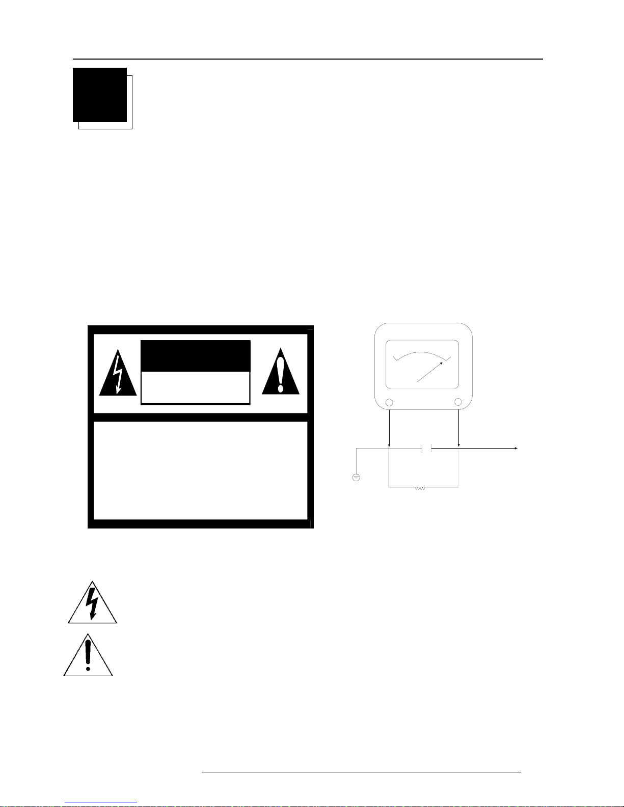
After re-assembly of the set, always m\perform an AC test on all
exposed metallic parts of the cabinet to be sure that set is safe to
operate without danger of electrical shock. DO NOT USE A LINE
ISOLATION TRANSFORMER DURING THIS TEST. Use an AC
voltmeter having 5000 ohms per volt or more sensitivity in the
following manner: Connect a 1500 ohm, 10 watt resistor,
paralleled by a 0.15 mfd 150V AC type capacitor between a
known good earth ground (water pipe, conduit, etc.) and the
exposed metallic parts, one at a time. Measure the AC voltage
across the combination of 1500 ohm resistor and 0.15 mfd
capacitor. Reverse the AC plug by using a non-polarized adaptor
and repeat AC voltage measurements for each exposed metallic
part. Voltage measured must not exceed 5.25 volts RMS. This
corresponds to 3.5 milliamp AC. Any value exceeding this limit
constitutes a potential shock hazard and must be corrected
immediately.
1500 OHM
Place this probe
on each exposed
meta l p a rt.
0.15 uF
10 WATT
G
ood Earth Ground
S
uch as the Water
P
ipe, Conduit, etc.
A.C. Voltm eter
RISK OF ELECTR IC SHOC K
DO NOT OPEN
WARNING
WARNING: TO REDUCE THE RISK OF ELECTRIC SHOCK,
DO NOT REMOVE COVER (OR BACK)
NO USER SERVICEABLE PARTS IN SIDE
REFER SERVICING TO QUALIFIED SERVICE PERSONNEL
Page 7

Safety instructions
1-2 206-3610 ZENITH PRO 1200X 151199
thinner or benzine, or abrasive cleaners, since these will damage
the cabinet.
To ensure the highest optical performance and resolution, the
projection lenses are specially treated with an anti-reflective coating,
therefore : avoid touching the lens. To remove dust on the lens, use
a soft dry cloth. Do not use a damp cloth, detergent solution, or thinner.
On AC Power
1. This product should be operated from an AC power source
only.
This product is designed to operate from either a nominal
system voltage of 120V or 240V.
However, this product has been shipped from the factory
equipped with a standard three conductor North American
power supply cordset for connection to a 15 A, 125 V, 60 Hz
branch circuit receptacle outlet.
If you are not sure of the type of AC power available, consult
your dealer or local power company.
If the power supply is not the correct one, consult your dealer.
2.THIS EQUIPMENT MUST BE GROUNDED (EARTHED) via the
supplied 3 conductor AC power cable. (If the supplied power
cable is not the correct one, consult your dealer.)
3. Do not allow anything to rest on the power cord. Do not locate
this product where people will walk on the cord. To disconnect
the cord, pull it out by the plug. Never pull the cord itself.
4. If an extension cord is used with this product, make sure that
the total of the ampere ratings on the products plugged into the
extension cord does not exceed the extension cord ampere
rating. Also make sure that the total of all products plugged into
the wall outlet does not exceed 15 amperes.
On installation
* Before operating your projector please read this manual thoroughly,
and retain it for future reference.
* Installation and preliminary adjustments should be performed by
qualified ZENITH personnel or authorized ZENITH service dealers.
* Do not place this projector on an unstable cart, stand, or table. The
projector may fall, causing serious damage to it.
* Do not use this projector near water.
* Use only the power cord supplied with your projector. While
appearing to be similar, other power cords have not been safety
tested at the factory and may not be used to power the projector.
For a replacement power cord, contact your dealer.
* Slots and openings in the cabinet and the sides are provided for
ventilation; to ensure reliable operation of the projector and to
protect it from overheating, these openings must not be blocked or
covered. The openings should never be blocked by placing the
product on a bed, sofa, rug, or other similar surface. This product
should never be placed near or over a radiator or heat register. This
projector should not be placed in a built-in installation or enclosure
unless proper ventilation is provided.
On Cleaning
Unplug this product from the wall outlet before cleaning. Do
not use liquid cleaners or aerosol cleaners. Use a damp cloth
for cleaning.
To keep the cabinet looking brand-new, periodically clean it with a soft
cloth. Stubborn stains may be removed with a cloth lightly dampened
with mild detergent solution. Never use strong solvents, such as
Page 8
Unpacking and dimensions
2
UNP ACKING AND PROJECT OR DIMENSIONS
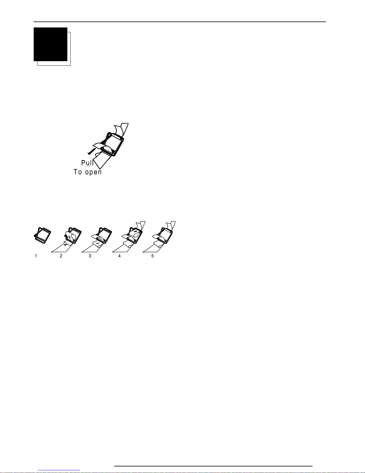
Unpacking
To open the banding around the carton, pull out the clip as shown
below :
Take the projector out of its shipping carton and place it on a table.
Save the original shipping carton and packing material, which will
come in handy if you ever have to ship your projector. For maximum
protection, repack your projector as it was originally packed at the
factory.
Contents of the shipping carton :
❒ 1 ZENITH PRO 1200X projector
❒ 1 Remote Control Unit plus 1 battery 9V
❒ 1 power cordset with outlet plug type ANSI 73.11
❒ 1 Owner's Manual
❒ 1 Installation Manual
206-3610 ZENITH PRO 1200X 151199
2-1
Page 9

Unpacking and dimensions
Projector dimensions (in mm)
APPROXIMATE WEIGHT WITH HD8 LENS - 67 KG
CRT
R7626572
R7626575
R7626576
R7627612
R7627615
590
456
558
576
FRONT IR RECEIVER
R7627616
CRT POINT
A
806 209
816 211
286
226
170
B
1040
A
596
ROTATION COVER
*SERVICE*
84
27
45.5
136
169.5
728
960
GRAVITY POINT
CRT POINT
362
B
MAX 500
POWER SUPPLY
510
590
BACK IR RECEIVER
AIRFLOW
AIRFLOW
AIRFLOW
703148
MAX 428
MAX 1076
AIRFLOW
FIXATION POINT
*4 X M8*
2-2 206-3610 ZENITH PRO 1200X 151199
Page 10

Installation guidelines
3-1
206-3610 ZENITH PRO 1200x 151199
3
INSTALLATION GUIDELINES
Installation guidelines
Careful consideration of things such as image size, ambient light
level, projector placement and type of screen to use are critical
to optimize the use of the projection system.
Environment
Do not install the projection system in a site near heat sources such
as radiators or air ducts, or in a place subject to direct sunlight,
excessive dust or humidity. Be aware that room heat rises to the
ceiling; Make sure the temperature near the installation site is not
excessive.
What about ambient light ?
The ambient light level of any room is made up of direct or indirect
sunlight and the light fixtures in the room. The amount of ambient light
will determine how bright the image will appear. So, avoid direct light
on the screen as much as possible.
Windows that face the screen should be covered by opaque drapery
while the set is being viewed. It is desirable to install the projecting
system in a room whose walls and floor are of non-reflecting material.
The use of recessed ceiling lights and a method of dimming those
lights to an acceptable level is also important. Too much ambient light
results in a ‘wash out’ of the projected image. This appears as less
contrast between the darkest and lightest parts of the image. With
bigger screens, the ‘wash out’ becomes more important. As a general
rule, darken the room to the point where there is just sufficient light to
read or write comfortably. Spot lighting is desirable for illuminating
small areas so that interference with the screen is minimal.
What image size? How big should the image
be?
The projector is designed for projecting an image width from 1.4m
(4.6') to 6m (20') with an aspect ratio of 4 to 3. It leaves the factory,
adjusted as a ceiling/front projector for a screen width of 2.4m (7.8').
Changing the image size from the factory preset size requires a
realignment of the projector.
Which screen type?
There are two major categories of screens used for projection
equipment. Those used for front projected images and those for rear
projection applications.
Screens are rated by how much light they reflect (or transmit in case
of rear projection systems) given a determined amount of light
projected toward them. The ‘GAIN’ of a screen is the term used. Front
and rear screens are both rated in terms of gain. The gain of screens
range from a white matte screen with a gain of 1 (x1) to a brushed
aluminized screen with a gain of 10 (x10) or more. Another important
consideration is the degree the screen's gain varies with the horizontal and vertical viewing angle. The choice between higher and lower
gain screens is largely a matter of personal preference.
In considering the type of screen to choose, determine where the
viewers will be located and go for the highest gain screen possible.
A high gain screen will provide a brighter picture but reduce the
viewing angle.
For more information about screens, contact your local screen
supplier.
Page 11
Installation guidelines
3-2 206-3610 ZENITH PRO 1200x 151199
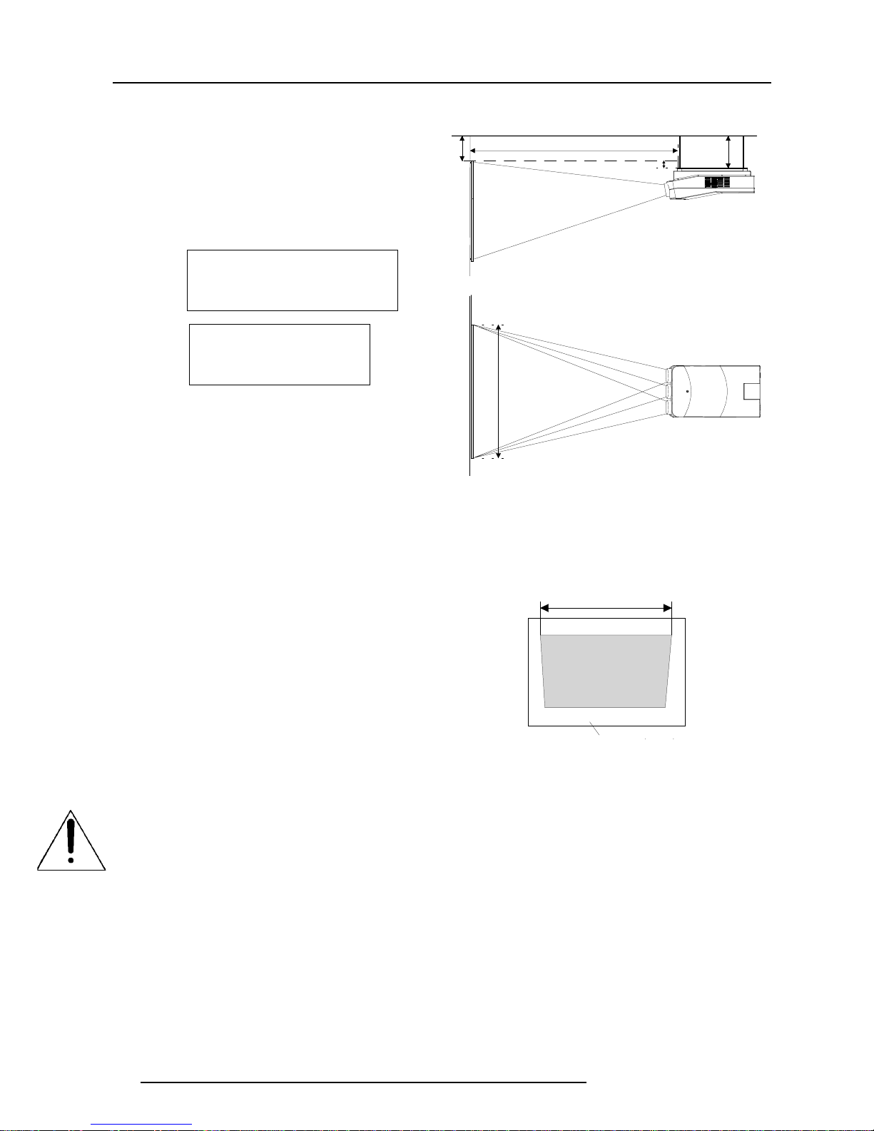
Where to install the projector ?
To indicate a correct installation position it is necessary to know :
• The distance from projector to ceiling in case of Ceiling
mounted or the distance from projector to floor in case of Table
mounted;
• The distance from projector to screen.
To find the correct position for the projector, use the following
formulas:
Abbreviations used in the calculations and the drawings :
• Install the projector water levelled in both directions
• Install the projector perpendicular to the screen
A
CD
PD
B
Screen
Projector
Ceiling
Screen width
SW
Front view
Top view
PD[inch] = 1.269 x SW[inch] + 7.12
A[inch] = 0.12 x SW[inch] - 9.70
In metric :
In inch :
PD[cm] = SW[cm] x 1.1358 + 18.53[cm]
A[cm] = SW[cm] x 0.142 - 25.26[cm]
B = Distance between ceiling and top of the screen (Ceiling
mounted) or distance between floor and bottom of the screen
(Table mounted).
A = Correction Value, extra value to be added to B to obtain the
correct installation position (In some cases the A value can be
negative).
CD = Total distance between projector and ceiling (Ceiling mounted)
or total distance between projector and floor (Table mounted).
CD = A + B.
Ceiling Mounted : when the result is negative, enlarge the
distance between ceiling and top of the screen, mount screen
lower, until CD becomes zero or positive.
Table Mounted : when the result is negative, enlarge the
distance between floor and bottom of the screen, mount
screen higher, until CD becomes zero or positive.
SW= Screen width.
PD = Perpendicular distance between screen and projector's mount.
To obtain the right values, you can make use of the new option
included in the Installation Adjustment Mode to let the projector
calculate the parameters automatically. Please refer to Chapter 8 for
details.
11.5 cm
green phospho
Used phosphor width on the CRT faceplate (e.g. green CRT)
Mounting Configuration
Ceiling Mount
To install the ZENITH PRO 1200x in the Ceiling configuration, use
ZENITH'S Ceiling Mount Kit (PJR1200CE). Installation instructions
are included with this kit.
Table Mount
ZENITH offers a heavy-duty projection table with adjustable height
which allows the projector to be correctly positioned perfectly to the
installation requirements.
(4.5 inch)
Green phosphor
On illumination
In order to obtain the best quality for the projected image, it is essential
that the ambient light which is allowed to fall on the screen be kept
to an absolute minimum.
When installing the projector and screen, care must be taken to avoid
exposure to ambient light directly on the screen. Avoid adverse
illumination on the screen from direct sunlight or fluorescent lighting
fixtures.
The use of controlled ambient lighting, such as incandescent spot
light or a dimmer, is recommended for proper room illumination.
Where possible, care should also be taken to ensure that the floors
and walls of the room in which the projector is to be installed are nonreflecting, dark surfaces. Brighter surfaces will tend to reflect and
diffuse the ambient light and hence reduce the contrast of the
projected image on the screen.
Page 12

Installation setup
4-1
206-3610 ZENITH PRO 1200x 151199
4
INSTALLATION SETUP
Removing the top cover
During some installations, it will be convenient to remove the top cover
from the projector totally.
Proceed as follows :
• Pivot the top cover backwards 90° (fully extended);
• Push carefully the top cover to the left side (viewing from the rear
of the projector) until the hinges are disengaged. This can be
facilitated by pressing downwards on the spring tabs next to the
hinges. Slide the top cover off the projector.
Reinstalling the top cover
To reinstall the top cover on the projector :
• Place the top cover in front of the hinges (as shown in the picture)
and push in the direction of the black arrow until the cover locks
into the hinges;
• Pivot the top cover to close;
• Secure the locking screw by turning it clockwise with a screw-
driver.
WARNING :
Risk of electric shock !
Installation only by ZENITH authorized service personnel !
Access to Controls
Opening the top cover
During the projector setup and installation it is necessary to open the
top cover. Follow the procedure described below :
• Turn the locking screw with a screwdriver counter clockwise;
• Lift up and pivot the top cover.
WARNING :
The projector's top cover is not supported with locking hinge. Open
with care and support the cover with your hand.
Page 13

Installation setup
4-2 206-3610 ZENITH PRO 1200x 151199
Scan Adaptation
The scan switches must be placed in the correct position which corresponds to the desired scanning configuration.
To change the scanning, it is necessary to remove the projector top cover and to open the protection plate.
For opening the projector's top cover, see 'Access to Controls'.
WARNING !
TURN OFF PROJECTOR AND UNPLUG THE POWER
CORD BEFORE CHANGING THE SCAN DIRECTION.
- Repeat this action on both sides of the module and extract the
module out of the main frame.
Side view
Top view
Top view
Side view
Push
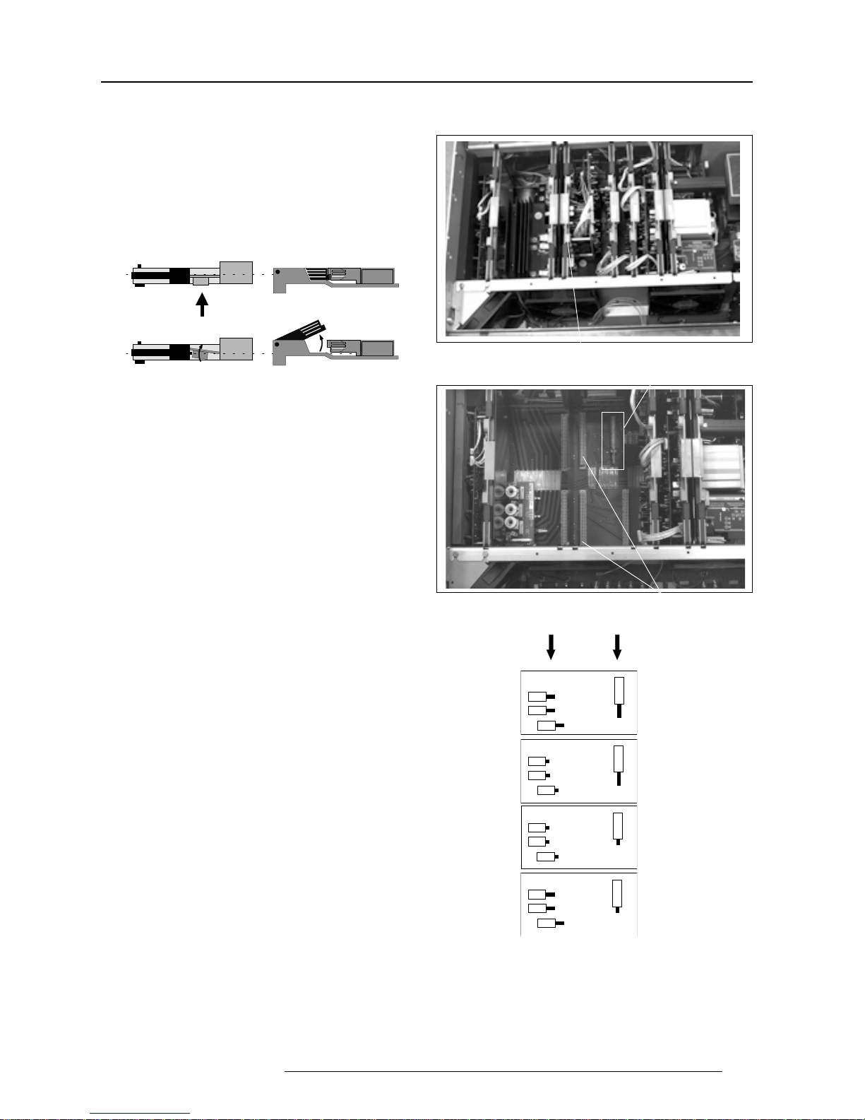
Three switches are used, one for each CRT. When changing the
horizontal scan, insure that all three switches are set in the same
position. See positions of the switches (diagram on next page) for
the corresponding projector configuration.
To set the scan switches :
• Remove the horizontal deflection module (the second module
viewing from the rear of the projector).
To remove the horizontal deflection module :
- Press the module lock and lift up the module handle;
Horizontal deflection module
• Toggle the 3 horizontal scan inversion switches (located just
underneath the horizontal amplitude module) to the correct
positions (see p.4-3).
• Reinstall the horizontal deflection module.
• Open the top cover and remove it from
the projector (see p.4-1);
• Loosen the 3 retaining screws on each
side of the projector;
• Open the protection plate and pivot it
forward (toward lenses).
Getting access to the scan switches
Horizontal scan switches
Horizontal amplitude
module
Connectors for the
horizontal deflection module
Horizontal Scan Switches
Page 14
Installation setup
4-3
206-3610 ZENITH PRO 1200x 151199
- Press the module lock and lift up the module handle;
- Repeat this action on both sides of the module and extract the
module out of the main frame.
Side view
Top view
Top view
Side view
Push
Connectors for the vertical
deflection module
Vertical scan switch
FRONT - TABLE
REAR - TABLE
REAR - CEILING
FRONT - CEILING
Vertical s can
switch
Horizontal
scan switches
Vertical Scan Switch
One vertical switch is used for the three CRT's. See position of the
switch (diagrams) for the corresponding projector configuration.
To set the vertical scan switch :
• Remove the vertical deflection module (the third module viewing
from the rear of the projector).
To remove the vertical deflection module :
Vertical deflection module
• Toggle the vertical scan inversion switch to the correct position.
• Reinstall the vertical deflection module.
Positions of the scan switches for the different mounting configurations are illustrated on the right side.
After setting the scan switches, close the metal protection plate and
secure it with the retaining screws.
Close the top cover and reconnect the power cord to the wall outlet.
Note : Switching over from Floor to Ceiling or vice versa
requires a complete readjustment of picture geometry and
convergence.
Page 15

Installation setup
4-4 206-3610 ZENITH PRO 1200x 151199
To check the current positions of the scan switches,
proceed as follows:
Attention : This procedure can only be done after power (mains)
connection. So, first continue with the projector setup
and the connections and then return to this procedure.
• Switch on the projector. The projector starts up on the last
selected source.
• Press the <ADJUST> key.
• Highlight 'SERVICE' by pushing the control stick forward or
backward and press the <ENTER> key: the 'SERVICE MODE
MENU' will be displayed.
SERVICE MODE
IDENTIFICATION
COPY A BLOCK
DELETE A BLOCK
DELETE ALL BLOCKS
CHANGE PASSWORD
CHANGE LANGUAGE
RUN TIME
DYNAMIC ASTIGMATISM
MORE...
Sele c t w ith or
then < E N T E R>
<E XIT> to retu rn
• Highlight 'IDENTIFICATION' by pushing the control stick forward
or backward and press the <ENTER> key.
The projector will display the 'IDENTIFICATION SCREEN'.
This screen gives the current information about the projector
configuration in the line entitled 'Config'.
All projectors leave the factory set for a ceiling/front configuration.
ADJUSTMENT MODE
Select a path from below:
IDENTIFICATION
GUIDED
RANDOM ACCESS
INSTALLATION
SERVICE
PROVERGE
SOURCE 1
Sele c t w ith or
then < E N T E R>
<E XIT> to retu rn
Page 16

Projector setup
5-1
206-3610 ZENITH PRO 1200x 151199
5
PROJECTOR SETUP
StdBY
MAIN POWER
PROC ESS OR C Y C
BLOCK MATCH
ERROR
RCU
RCVDS
PC
PA USE
PROJECTOR ADDRESS
(sum)
OFF ON
BAUD RATE TABLE
TO C O M P UTE R
POWER UP M ODE
OPERATING MODE WHEN
POW ER IS S W ITCHED ON
ON
OFF
PLAYING
StdBY
PASSWORD MODE
ON
OFF
YES
NO
RESERVED
POWER UP MODE
PASSWORD MODE
BA UD RA TE CODE
(sum)
PASSWORD REQUIRED
FOR ADJUSTMENT
CODE
0
1
2
3
4
5
6
7
SPEED
110
150
300
600
1200
2400
4800
9600
0
1
128
64
32
16
8
4
2
1
1
2
3
4
5
6
7
8
1
2
3
4
2
1
1
2
3
4
5
6
7
8
I
2
C SHORTED
Setting the projector address
The projector's address may be set to any value between 0 and 255.
When the address is set, the projector can be controlled now by :
• RCU for addresses between 0 and 9.
• IBM PC (or compatible) or Apple MAC for addresses between 0 and
255.
The DIP switches on the controller board allow the SETUP of the
projector :
• 8 DIP switches for setting the projector address.
• 1 DIP switch for setting the powerup mode.
• 3 DIP switches for setting the baud rate for communication.
• 1 DIP switch for setting the password mode.
To gain access to the DIP switches :
- Open the top cover.
- Loosen the retaining screws of the metal protection plate and pivot
this plate to the lens side (Please refer to Chapter 4 'Installation
setup').
The DIP switches are located on the back side of this metal protection
plate.
Addressable with RCU
Addressable with PC, MAC
or workstation
0
9
255
PROCESS CYCLE
I2C SHORTED
Page 17

Projector setup
5-2 206-3610 ZENITH PRO 1200x 151199
1 128
2 64
3 32
4 16
5 8
6 4
7 2
8 1
Setting the address is a hardware SETUP of your projector which
must be done during installation. Use the 8 DIP switches provided on
the controller board labelled 'Projector Address'.
Each DIP switch has its own decimal value. The sum of the values
associated to those DIP switches gives the address. As shown in the
table, if Switch No. 1 is set to ON, it represents a decimal value of 128,
Switch No.2 for 64, Switch No.3 for 32, and so forth.
In the given example, the projector address is set to 202 :
DIP switch No. : 1 2 3 4 5 6 7 8
Position ON/OFF : 1 1 0 0 1 0 1 0
Sum : 1x128 + 1x64 + 0x32 + 0x16 + 1x8 + 0x4 + 1x2 + 0x1 = 202
Factory preset address = 0
Note :
When the address button on the RCU is pressed, the projector will
display its own address on the screen. Once the address button is
pressed, to continue using your RCU, it is necessary to enter an
address, even when the displayed address is correct. Use the
numeric keys to enter the address.
For more information, please refer to the projector Owner's Manual .
1
2
3
4
5
6
7
8
0
1
OFF ON
1
2
3
4
5
6
7
8
ON
OFF
Power-up mode
OFF ON
Powerup mode
The projector can start up in two different modes. The start-up mode
is determined by the position of DIP Switch No. 4 of another set of 8
DIP switches on the controller board (one set of 8 switches are used
for projector address setting).
Position of the DIP Switch No. 4 (powerup mode) :
ON : operational mode.
OFF: standby mode (Factory preset).
Source 2
Fh= 15.6 kHz
Fv= 50 Hz
• Operational mode
When the power switch on the rear of the projector is pressed, the
projector displays the last selected source if available, otherwise it
remains on that source number until the source becomes available.
The on screen indication is only available when the "Text" function is
set to "ON".
• Standby mode
When the power switch on the rear of the projector is pressed, the
projector starts up in the standby mode. The standby key on the RCU
is used to turn the projector ON and OFF.
Switch No Value
PROJECTOR
ADRESS
001
Page 18

Projector setup
5-3
206-3610 ZENITH PRO 1200x 151199
Position of DIP switches and baud rate codes :
Baud Rate for communication with a
computer
The communication speed between the projector and the computer
has 8 possible settings. With DIP Switch No. 6, No.7 and No.8 of the
8 DIP switches on the controller board, labelled as ‘Baud rate code
(sum)’, it is possible to select the baud rate (communication speed).
Each DIP switch has its own decimal value. The sum of the values
associated to those DIP switches gives the baud rate code. Each
baud rate code corresponds an communication speed.
1
2
3
4
5
6
7
8
OFF
ON
0
1
Baud rate
DIP switches
4
2
1
Password mode
With DIP Switch No.5 of the second set of 8 DIP switches on the
controller board, the projector adjustments can be protected with a
password. When the password feature is enabled, the user has to
enter a password before he can enter the adjustment mode (For more
information about password setting and reprogramming the password, see Installation Adjustment).
When the password menus are disabled (adjust mode is unprotected), the adjust mode can be selected by pressing the <ADJUST>
key. This position of the DIP switch is useful for qualified service
technicians because they do not need a password to enter the adjust
mode.
Position of DIP Switch No.5 :
ON : password mode enabled.
OFF : password mode disabled.
Factory preset password mode : OFF.
Factory preset baud rate = 9600
More information about computer communication with the ZENITH
PRO 1200X is available in the Projector Control Software manual.
Password
mode
1
2
3
4
5
6
7
8
OFF
ON
0
1
Binary Baud rate code Speed
000 0 110
001 1 150
010 2 300
011 3 600
100 4 1200
101 5 2400
110 6 4800
111 7 9600
Page 19

Projector setup
5-4 206-3610 ZENITH PRO 1200x 151199
Page 20

Source connections
6-1
206-3610 ZENITH PRO 1200X 151199
4/5 Component video 8
with Tri-level sync
R, G and B with composite sync on Green;
3 RGB 3 R, G and B with separate composite or with separate Horizontal
and Vertical sync.
Port No Projector input Numeric button Description of input signal
1 Composite Video 1
S-video : Y/C (luma/chroma).
The Composite video can also be connected to Port 2. It can be
2 S-Video / Composite Video 2 selected inside the "Picture Tuning" menu. Please refer to the
Owner's Manual of this projector.
6
SOURCE CONNECTIONS
Signal input connection
The following signals can be connected to the projector through the
inputs on the back panel of the projector :
• Composite Video
• S-Video
• RGB
• Component Video
• RGB with Tri-level sync
• Component video with Tri-level sync
ONOFF
POWE R / MAIN S
800 per iphe rals
RGB
Comp-/H-Sync V-Sync
COMM. PORT POR T 3
PORT 4/5
V-nom
I-nom
Freq
See inst allation instructi ons b efore conn ecting to th e supply .
Voir la no t ice d 'i nst al lati o n av ant de raccor d er au réseau .
120/230 V
7/5 Amp
50/60 Hz
S-VIDEO OFF - ON
75 Ohm
VIDEO
green : operation
red : standby
PORT 2
PORT 1
OFF - ON
75 Ohm
PROJECTOR MODE
123 4 5
This device complies with part 15 of
the FCC rules. Operation is subject to
following two co n d ition s (1). This
device may not cause harmful interference, and (2) this device must
accept any interference received
including interference that may cause
undesired op er a tion"
75 Ω Termination Switch
R, G and B with composite sync on Green;
4/5 RGB 4 or 5 R, G and B with separate composite or with separate
Horizontal and Vertical sync.
R-Y, Y, B-Y with composite sync on Y;
4/5 Component video 6 or with separate composite or with separate Horizontal and
Vertical sync.
R, G and B with Tri-level sync on Green;
4/5 RGB with Tri-level sync 7 R, G and B with separate Tri-level sync or with separate
Horizontal and Vertical Tri-level sync.
R-Y, Y, B-Y with Tri-level sync on Y; or with separate Tri-level
sync or with separate Horizontal and Vertical Tri-level sync.
Connecting a Composite Video source to
Port 1
Composite video signals coming from a VCR, OFF air signal decoder
and so on can be connected to Port 1.
To select the video input :
Press the numeric button 1 on the RCU or the local keypad.
75 W Termination Switch for Video
Terminate the video input of the projector using the 75W switch next
to the video input, when the projector operates alone or when the
projector is the last unit in a loop-through configuration.
The switch is set to "ON" : signal terminated.
The switch is set to "OFF" :signal not terminated.
Page 21

Source connections
6-2 206-3610 ZENITH PRO 1200X 151199
Connecting a S-Video (or Composite Video)
source to Port 2
Separate Y-luma/C-chroma signals for higher quality playback of
Super VHS signals can be connected to Port 2 . The composite video
can also be connected to this port.
To select the S-video input :
Press the numeric button 2 on the RCU or the local keypad.
In case of using Port 2 for connecting the Composite Video, the
selection of this source have to be done inside the "Picture Tuning"
menu. Please refer to the Owner's Manual of this projector.
75 W Termination Switch for S-video
Terminate the S-video input of the projector using the 75 W switch
next to the S-video input when the projector operates alone or when
the projector is the last unit in a loop-through configuration.
The switch is set to "ON" :signal terminated.
The switch is set to "OFF" :signal not terminated.
Connecting a RGB Analog source to Port 3
Connect a RGB Analog signal via an interface (e.g. RGB 120MHz
interface, part number 98 26570) to Port 3: RGB analog input with
automatic sync detection (Separate H and V sync inputs, with
composite sync input or with sync signals on green).
Pin configuration of the D9 (male) connector of the Analog input :
1 not connected
2 ground RGBS
3 RED
4 GREEN
5 BLUE
6 ground RGBS
7 ground RGBS
8 Horizontal /composite sync
9 Vertical sync
To select the RGB analog Input :
Press the numeric button 3 on the RCU or the local keypad.
S1 Force Negative Sync
(ON=yes)
R81
Hsync
R101
Vsync
R41
(Blue)
R21
(Green)
R1
(Red)
S2 Blue in Green (ON=yes)
Line termination 75 Ω resistors
75 Ω Termination Switch
1
2
3
4
4 pin connector configurations:
For S-video:
Pin 1: earth(ground) luminance
Pin 2: earth(ground) chrominance
Pin 3: luminance signal(Y)
1Vpp ±3dB
Pin 4: chrominance signal(C)
300mVpp ±3dB
For video:
Pin 1: earth(ground) video
Pin 2: not connected
Pin 3: video signal
Pin 4: not connected
Locations of the Termination Resistors and Switches
on the RGB Input Auto Sync Tracking Module
When changing a switch position or removing a resistor, turn off the
projector and unplug the power cord from the wall outlet.
75 W Termination resistors
In case of chaining (loop-through) the projectors, the 75W line
termination resistors must be removed from the RGB Input Auto Sync
Tracking Module when the projector is NOT the last unit in the chain.
In case of a stand-alone projector, do not remove the resistors.
75 W resistors on the module : line terminated.
75 W resistors removed : line not terminated.
ONOFF
POWE R / MAINS
800 peripherals
RGB
Comp-/H-S yncV-Sync
COMM. PORT PORT 3
PORT 4/5
V-nom
I-nom
Freq
See installation instructions before connecting to the supply.
Voir la noti ce d'installation av ant de raccorder au réseau.
120/230 V
7/5 Amp
50/60 Hz
S-VIDEO OFF - ON
75 Ohm
VIDEO
green : operat ion
red : standby
PORT 2
PORT 1
OFF - ON
75 Ohm
PROJECTOR MODE
inver.
75 ohm term.
This device complies with part 15 of
the FCC rules. Operation is subject to
following two conditions (1). This
device may not cause har mful interference, and (2) this device must
accept any interference received
including interference that may cause
undesired operation"
RGB 120MHz interface
Page 22

Source connections
6-3
206-3610 ZENITH PRO 1200X 151199
RGB Input Auto Sync Tracking Module
Procedure to remove the line termination resistors :
• Turn off the projector and unplug the projector power cord.
• Remove the top cover from the projector (see p.4-1).
• Remove the RGB Input Auto Sync Tracking Module from the main
frame.
• Unsolder and remove the resistors.
To remove the RGB Input Auto Sync Tracking Module, follow the same
procedure as described in p.4-2 for removing the Horizontal Deflection module :
• Press the module lock and lift up the module handle;
• Repeat this action on both sides of the module and extract the
module out of the main frame.
Blue in Green Switch on the RGB Input Auto Sync
Tracking Module
Blue characters are difficult to read, therefore the blue text will be
displayed as cyan so that the readability becomes better.
Switch in the ON position : Blue in Green active.
Switch in the OFF position : Blue in Green disabled.
WARNING : Leaving the switch in the ON position will result in
abnormal color balance of the projected image.
Force Negative Sync on the RGB Input Auto Sync
Tracking Module
Switch in the ON position : the sync pulses must be negative.
Switch in the OFF position : the sync polarity will be automatically
detected.
Connecting a RGB Analog source to Port 4/5
RGB analog input terminals with separate H and V sync inputs,
composite sync input or sync signals on green can be connected to
the projector via Port 4/5. The projector automatically detects where
the sync signal is located.
An interface is recommended when connecting a computer and local
monitor to the projector.
To select the RGB input :
Press the numeric button 4 or 5 on the RCU or the local keypad.
Connecting a Component Video source to
Port 4/5
A component video (R-Y, Y, B-Y) with sync signals can be connected
to the projector via Port 4/5. The projector automatically detects
where the sync signal is located.
To select the component video input :
Press the numeric button 6 on the RCU or the local keypad.
inver.
75 ohm te rm.
Interface
ONOFF
POWE R / MAIN S
800 periphe r a ls
RGB
Comp-/H-SyncV-Sync
COMM. PORT PORT 3
PORT 4/5
V-nom
I-nom
Freq
See installatio n instruction s before co n necting to the sup pl y.
Voir la n ot ice d 'installation a v ant de racco rd er au réseau.
120/230 V
7/5 Amp
50/60 Hz
S-VIDEO OFF - ON
75 Ohm
VIDEO
green : operation
red : standby
PORT 2
PORT 1
OFF - ON
75 Ohm
PROJECTO R MODE
798
This de v ice c o mplie s with p a r t 1 5 of
the FCC rules. Operation is subject to
followin g two cond itions (1). This
dev ice m ay no t cau se h a r mful inter feren ce, a nd (2 ) this d ev ic e mu st
accept any interference received
including interference that may cause
undesired operation"
Page 23

Source connections
6-4 206-3610 ZENITH PRO 1200X 151199
Connecting a RGB Analog source with Trilevel sync to Port 4/5
RGB analog input terminals with Tri-level sync input or with Tri-level
sync on green can be connected to the projector via Port 4/5. The
projector detects automatically where the sync signal is located. This
feature requires an optional Tri-Level Sync Module.
To select the input :
Press the numeric button 7 on the RCU or the local keypad.
ONOFF
POWER / MAIN S
800 peripherals
RGB
Comp-/H-SyncV-Sync
COMM. PORT PORT 3
PORT 4/5
V-nom
I-nom
Freq
See installation instructions before connecting to the supply.
Voir la notice d'installation avant de raccorder au réseau.
120/230 V
7/5 Amp
50/60 Hz
S-VIDEO OFF - ON
75 Ohm
VIDEO
green : opera tion
red : standby
PORT 2
PORT 1
OFF - ON
75 Ohm
PROJECTOR MODE
798
This device complies with part 15 of
the FCC rules. Operation is subject to
following two conditions (1). This
device may not cause harmful inter-
ference, and (2) this dev i c e m us t
accept any interference received
including interference that may cause
undesired operation"
Connecting a Component Video source with
Tri-level sync to Port 4/5
Component video inputs with Tri-level sync signal can be connected
to the projector via Port 4/5. The projector detects automatically
where the sync signal is located. This feature requires an optional TriLevel Sync Module.
To select the input :
Press the numeric button 8 on the RCU or the local keypad.
Page 24

Installation adjustment mode
7
INSTALLATION ADJUSTMENT MODE
Access to Installation Adjustment Mode
It will be necessary to perform several mechanical adjustments while
in the Installation Adjustment Mode. It will be required to open and
remove the projector's top cover in order to gain access to the
adjustment points.
To enter into the installation adjustment mode :
Press the <ADJUST> key to start up the adjustment mode.
Push the control stick forward or backward to highlight the path
INSTALLATION in the "Adjustment mode" menu and then press
the <ENTER> key.
A warning will be displayed on the screen. If you are a qualified and
authorized service person, press the <ENTER> key to start up the
installation mode. Otherwise, press the <EXIT> key to return.
When entering the installation mode, the projector will automati-
cally switch to the internal pattern on 15 kHz/60 Hz.
When the password mode is active (see p.5-3), you will be
requested to enter the 4 digit password.
Enter the digits with the numeric keys on the RCU or the local
keypad.
ADJUSTMENT MODE
Select a path from
below:
GUIDED
RANDOM ACCESS
INSTALLATION
SERVICE
PROVERGE
WARNING
RISK OF ELECTRICAL SHOCK
NO USER ADJUSTABLE PARTS
INSIDE
THE FOLLOWING
THE FOLLOWING INSTALLATION
INSTALLATION MENUS
MENUS ARE RESERVED TO AND TO
ARE RESERVED TO,
BE PERFORMED BY ZENITH
AND TO BE PERFORMED ONLY
PERSONNEL OR ZENITH
BY BARCO PERSONNEL, OR
AUTHORIZED DEALERS
BARCO AUTHORIZED DEALERS
IF QUALIFIED, PRESS <ENTER> TO
IF QUALIFIED, PRESS
CONTINUE OR
<ENTER> TO CONTINUE, OR
IF NOT, <EXIT> TO RETURN.
Example : Password as 2 3 1 9
For each digit entered, a 'X' appears on the screen under the
displayed text 'enter password'.
If the entered password is correct, you get access to the 'Installation Adjustment Mode'.
If the entered password is wrong, The message "Wrong pass-
word!!!" will be displayed. The projector stays on the previous
selected item.
Factory programmed password :
0 0 0 0
Overview flowchart of the Installation Adjustment Mode
Adjustment Mode
Installation Raster CenteringProjector Distance Optical Lens Focusing
enter
password
xxxx
197
enter
password
Wrong Password !
xxxx
197
CRT Projection Angle Adjustment
206-3610 ZENITH PRO 1200X 151199
7-1
Page 25

Installation adjustment mode
Important : Access to adjustments
The top cover of the projector should be removed in order to gain
access to the adjustments.
Please refer to p.4-1 for how to remove the top cover.
Projector Distance
On the screen, a drawing will be displayed together with parameters
indicating a correct installation position.
To change the screen width :
Push the control stick to the left or to the right to highlight the item
SW in the "Projector Distance 1" menu and then press the
<TEXT> key.
If the <ENTER> key is pressed, the "Optical Lens Focusing" will be
displayed.
If the <EXIT> key is pressed, the projector will return to the
previous menu.
After the <TEXT> key is pressed, the next menu "Projector
Distance 2" will be displayed on the screen. It allows the user to
change the Screen width.
Push the control stick to the left or to the right to highlight the digit
needed to be changed, and enter the desired digit with the numeric
keys on the RCU or the local keypad.
Press the <ENTER> key to confirm the changes. The projector will
redisplay the "Projector Distance 1" menu with updated values for
the three parameters.
Press the <ENTER> key to continue with the "Optical Lens
Focusing".
If the <EXIT> key is pressed, the projector will return to the
previous menu.
&HLOLQJ
%
6FUHHQ
SW = 2.6 m PD= 3.64m A=12 cm
Select with arrow keys; <TEXT> to reprogram
<ENTER> to continue; <EXIT> to return.
WARNING: ONLY FOR STANDARD PROJECTORS !!
6FUHHQZLGWK
6:
Select with arrow keys; reprogram with numeric keys and
then <ENTER> to confirm.
Maximum screenwidth = 6 m
Maximum proj. distance = 8,1 m.
3'
A = Correction value
PD= Perpendicular distance between screen and projector
SW= Screen width
)URQWYLHZ
SCREENWIDTH = 2 , 6 0 m
7RSYLHZ
$
&'
3URMHFWRU
The same applies to the PD (projector distance). You can use the
above-mentioned procedure to obtain a correct updated value of SW
(screenwidth) after entering a new value of PD (projector distance).
Optical Lens Focusing
The optical focusing procedure is performed separately for each
lens. The appropriate CRT will be switched on as the user proceeds
through the optical focusing adjustment sequence.
Each lens has one focus adjustment points. The the projected image
is focused by loosening the wing nut of the lens and rotating the lens
barrel until the the image is clearly focused.
Press the <ENTER> key to continue. After finishing focusing of the
three lenses, press the <ENTER> key to enter the Raster centering.
Press the <EXIT> key to return to operational mode.
Press the <ADJUST> key to return to operational mode.
237,&$/ /(16)2 &86,1*
1. LOOSEN THE NUT ON THE
REAR OF THE GREEN LENS,
LOOSEN THE NUT ON THE xx LENS,
ROTATE THE LENS BARREL
ROTATE THE LENS BARREL TO FOCUSTHE
TO FOCU S THE CENTER
IMAGE.
OF THE IMAGE,
THEN TIGHTEN THE NUT
THEN TIGH TEN THE NUT
2. LOOSEN THE NUT ON THE
FRONT OF THE GREEN LENS
AND ROTATE THE FRONT
SECTION OF THE LENS TO
FOCUS THE CORNERS OF THE
IMAGE, THEN TIGHTEN THE NUT.
<ENTER> to continue
<EXIT> to return
xx = Green, Blue, Red
Focusing
7-2 206-3610 ZENITH PRO 1200X 151199
Page 26

Raster Centering
The raster must be centered on the CRT faceplate of each tube,
therefore, it is necessary to look into the lenses.
Caution : To avoid eye discomfort while performing these adjustments, reduce the contrast and gradually increase the brightness
level until the raster becomes visible behind the image.
Warning : In order to ensure maximum CRT
longevity and to avoid CRT damage, do not shift
the raster outside the phosphor area of the CRT.
Installation adjustment mode
5$67(5&(1 7(5,1*
CONTRAST LEVEL IS REDUCED
AND BRIGHTNESS INCREASED
TO MAKE THE RASTER
VISIBLE ON THE FACE PLATE
OF EACH CRT.
USE THE ARROW KEYS
TO CENTER THE RASTER
ON THE GREEN, RED AND
BLUE CRT RESPECTIVELY
<ENTER> to continue
<EXIT> to return
Press the <ENTER> key to display the raster on the green CRT.
Look into the green lens and shift the raster with the control stick until
it is centered in the middle of the CRT faceplate.
Press the <ENTER> key to activate the raster on the Red CRT
faceplate.
Shift the Red raster with the control stick until the raster is centered
on the CRT faceplate.
Press the <ENTER> key to activate the raster on the Blue CRT
faceplate.
Shift the Blue raster with the joy stick until the raster is centered on the
CRT faceplate.
Press the <ENTER> key to continue with the CRT projection angle
adjustment.
Press the <EXIT> key to return to Optical focusing.
Press the <ADJUST> key to return to Operational mode.
Forbidden area
Projected raster
CRT faceplate border
Phosphor area
Correct raster position
Wrong raster position
206-3610 ZENITH PRO 1200X 151199
7-3
Page 27

Installation adjustment mode
CRT Projection Angle Adjustment
The projection angle of the red and blue CRT's is dependent on the
desired size of the projected image. If the centers of green, blue and
red do not coincide, the CRT projection angle must be adjusted.
NOTE : Never try to correct this misalignment with the shift
correction or the static convergence controls. These controls
may only be applied to correct small errors which cannot be
corrected by the CRT angle adjustment.
Note: The Horizontal Shift and Vertical Shift for Red and Blue
should be set near 50%.
Be sure that the rasters are centered on the CRT faceplate.
Press the <ENTER> key to start the CRT angle adjustment procedure.
Press the <ENTER> key to continue with the second part of the CRT
projection angle adjustment.
Press the <ENTER> key to continue with the crosshairs alignment.
Press the <EXIT> key to return to the previous menu.
Press the <ADJUST> key to return to Operational mode.
Loosen bolts A, B, C and D to pivot the red CRT until the center of the
Red image and the center of the Green image coincide. When the
angle of the red CRT is corrected, tighten the four bolts.
Press the <ENTER> key to continue with blue and green crosshairs.
Press the <EXIT> key to return to the CRT projection angle adjustment menu.
CRT PROJECTION ANGLE
ADJUSTMENT
CRT PROJECTION ANGLE IS
THE FIRST STEP OF STATIC
CONVERGENCE ADJUSTMENT.
IT IS CRITICAL THAT THE
RASTERS ARE CENTERED ON
THE CRT FACE PLATES
PRIOR TO PERFORMING
THIS STEP.
...
<ENTER> to read more
<EXIT> to return
CRT PROJECTION ANGLE
ADJUSTMENT
DURING THIS PROCEDURE,
RED ON GREEN AND THEN
BLUE ON GREEN CROSSHAIRS
WILL BE DISPLAYED
TO ALLOW THE RED AND
BLUE CRTS TO BE ALIGNED
WITH THE GREEN CRT.
LOOSEN BOLTS A AND B
TO PIVOT THE RED CRT,
AND BOLDS C AND D
TO PIVOT THE BLUE CRT.
<ENTER> to continue
<EXIT> to return
PROJECT IO N AN GLE
ADJUSTMENT
CRT
Red crosshair
Green crosshair
Move the red CRT towards
the green CRT
Red crosshair
Green crosshair
Move the red CRT to the
outside, away from the
green CRT
$
%&
Align crosshairs
<ENTER> continue
<EXIT> to return
'(
)
*
+
7-4 206-3610 ZENITH PRO 1200X 151199
Page 28

Loosen bolts E, F, G and H to pivot the blue CRT until the center of the
Blue image and the center of the Green image coincide. When the
angle of the blue CRT is corrected, tighten the four bolts.
Press the <ENTER> key to continue with the diagonal focusing menu.
Press the <EXIT> key to return to the CRT projection angle adjustment.
Blue crosshair
Green crosshair
Move the blue CRT to the
outside, away from the green
CRT
Blue crosshair
Green crosshair
Move the blue CRT towards
the green CRT
Installation adjustment mode
CRT
PROJECT IO N AN GLE
ADJUSTMENT
Align crosshairs
<ENTER> continue
<EXIT> to return
Projection angle correctly aligned for screen width SW1.
The same projection angle is misaligned for new screen width SW2.
Realignment is necessary. Each screen width change requires
readjustment of the projection angle.
SW2
(SW1 > SW2)
206-3610 ZENITH PRO 1200X 151199
370b
7-5
Page 29

Installation adjustment mode
Scheimpflug adjustment
To adjust the Scheimpflug correction for each colour, follow the next procedure:
Step Action
1
First, be sure that the CRT projection angle is correctly adjusted, to ensure proper
overall focus of the image.
2
Example : diagonal focusing of the GREEN image.
Equalize diagonally the focus from left (bottom) to right (top) by turning screw G1 and from
left (top) to right (bottom) by turning screw G2.
3
Repeat the same procedure for the RED and BLUE image using the corresponding screws.
To optimize the image focusing, repeat the optical lens focusing.
4
+
+
+
+
Lenses
HD215
DIAGONAL IMAGE
FOCUSING
from left bottom to right top
+
+
E R OW 5
E R OW %
EROW*
FOCUSING
DIAGONAL IMAGE
FOCUSING
from l e ft top to rig h t bottom
+
E R OW 5
E R OW *
+
E R OW %
7-6 206-3610 ZENITH PRO 1200X 151199
5 5 * *
RED IMAGE
GREEN IM AGE
% %
BLUE IMAGE
Page 30

Messages, warnings and failure codes
9-1
206-3610 ZENITH PRO 1200X 151199
8
MESSAGES, W ARNINGS AND F AILURE CODES
SOURCE 01
Fh= 15.6 kHz
Fv= 060 Hz
SOURCE 01
Fh= 15.6 kHz
Fv= 060 Hz
Announcement of the selected
source.
enter
password
xxxx
Message to enter your password.
Password contains 4 digits.
text on
text off
These messages will be
displayed on the screen when
pushing the <TEXT> key.
Text ON : the 'Bar scale
indication' will be enabled during
the change of an analog control
in the 'Operational mode'. All
warning and failure messages
will be displayed.
Text OFF : the 'Bar scale
indication' will be disabled
during the change of an analog
control in the 'Operational mode'.
All warning and failure massages
will not be displayed.
PROJECTOR
ADDRESS :
003
WARNING :
input not
available
When using the projector with
the RCVDS, this warning will be
displayed when selecting an
input slot of an RCVDS where
the input board is missing.
When selecting a new source,
information about this source will
be displayed on the screen.
Source number, horizontal and
vertical frequencies of the
displayed source.
WARNING :
source not
available
The input is a valid input but the
source is not connected to the
input terminals or the input source
is switched off.
WARNING :
invalid
key entry
When a wrong key is pressed on
the RCU.
WARNING :
invalid
code entry
Message when the entered
password is wrong.
WARNING :
end of adjust range
End of adjustment range.
WARNING :
input no
longer
available
Message will be displayed when
the input source is no longer
available. The following message
then appears: 'check input
signal or select new source'.
This message will be displayed
after the message 'input no longer
available'. It asks to check the
connections between the source
and the projector or to check if
the source is switched on.
check input signal
or select
new source
WARNING :
input selector
not
available
It warns you to check the power
connection or the power status
of the RCVDS.
Next message will appear
immediately on the screen : 'go
to standby'.
Indication of the projector
address when activating the
'ADDRESS' button on the RCU
with a pencil or other small
object.
Page 31

Messages, warnings and failure codes
9-2 206-3610 ZENITH PRO 1200X 151199
WARNING :
go to
stand by
Projector will switch to 'Standby'
when the RCVDS is no longer
available.
WARNING :
invalid
frequency
input
The entered frequency or
applied frequency of the source
is out of the projector's range.
WARNING :
default
settings
loaded in
the E2PROM
Adjustment settings are lost.
Reload using Projector Control
Software via PC or MAC (if this
option is available), or readjust
image.
table is
deleted
Message to inform that selected
table is deleted. This message
will be followed by 'confirm
message', on which the user has
to answer.
FAILURE
invalid
RWI soft
version
Wrong software version in your
projector.
Call for technical support.
FAILURE
I2C error
addr. : 7FH3
Hardware failure. Call a
qualified service technician for
repair.
FAILURE
short
circuit on
I2C bus
Hardware failure. Call a
qualified service technician for
repair.
FAILURE
RWI commu-
nication
error
Hardware failure. Call a
qualified service technician.
FAILURE
ProVerge commu-
nication
error
Communication error between
ProVerge and the projector. Call
a qualified service technician.
WAIT
starting
up
ProVerge
Message during the start up of
the ProVerge.
Message will disappear when
the ProVerge is ready to accept
commands.
Page 32

Appendix A: G2 adjustment
A-1
206-3610 ZENITH PRO 1200X 151199
A
G2 ADJUSTMENT
Once the on-screen menu "G2 ADJUSTMENT" is displayed, proceed
as follows :
G2 ADJUSTMENT
<EX IT > to re tu rn
Use the potentiometers
on the G2-ADJ. module
to set the screen grid
voltage for Red,
Green and Blue.
Adjust until the LED
on the corresponding
out put amplifier is
turned off.
Retaining screws
• Remove the top cover from the projector (see p.4-1) and open the
front metal protection cover by turning out the 3 retaining screws on
both sides.
• A green LED is mounted on each of CRT sockets (see Photo 2).
When selecting the G2 adjustment menu, these green LEDs must
be out. If not, follow the procedure below to adjust the G2 :
- Open the second metal cover by turning out the retaining screws
on both sides and pivot the cover to the front side of the projector
(see Photo 1);
- Adjust the G2 potentiometers (see Photo 3) very slowly with a
plastic tweaker until the LED of the corresponding amplifier just
stops illuminating. Repeat the adjustment for the other colors;
- After the three G2 potentiometers have been correctly adjusted,
close both metal covers and secure with the retaining screws.
1
2
3
Red potentiometer
Blue potentiometer
Green potentiometer
After finishing the adjustments :
Press the <ENTER> key to continue with the "SERVICE" menu.
Press the <EXIT> key to return to the "SERVICE" menu.
Press the <ADJUST> key to return to Operational mode.
Green LEDs
Page 33

Appendix A: G2 adjustment
A-2 206-3610 ZENITH PRO 1200X 151199
Page 34

Gamma corrections
C-1
206-3610 ZENITH PRO 1200X 151199
B
GAMMA CORRECTIONS
When entering the gamma corrections, a warning will be displayed :
"RISK OF INCORRECT ADJUSTMENT OF THE PROJECTOR.
THE GAMMA CORRECTIONS ARE FACTORY ADJUSTED USING
AN ACTAS COLOR ANALYZER ! THEREFORE, ONLY QUALIFIED
INSTALLATION OR SERVICE PERSONNEL SHOULD PERFORM
THESE ADJUSTMENTS ! "
If you are qualified, press the <ENTER> key to continue.
WARNING
RISK OF INCORRECT
ADJUSTMENT OF THE
PROJECTOR.
THE GAMMA CORRECTIONS ARE
FACTORY ADJUSTED USING AN
ACTAS COLOR ANALYZER !
THEREFORE, ONLY QUALIFIED
INSTALLATION OR SERVICE
PERSONNEL SHOULD PERFORM
THESE ADJUSTMENTS !
<ENTER> TO CONTINUE
<EXIT> TO RETURN.
Gamma Corrections
Three items can be selected inside the "Gamma Corrections" menu:
the Blue Gamma Correction, the R & B midlights and the factory
preset.
To carry out the Blue Gamma Correction :
• Push the control stick forward or backward to highlight the item
BLUE GAMMA CORRECTION in the menu and then press the
<ENTER> key.
If the <EXIT> key is pressed, the projector will return to the Service
menu.
• After the <ENTER> key is pressed, a text box with the message,
"Adjust with arrow key", will be displayed on the screen.
• Push the control stick forward or backward to adjust the slope, a
text box with a bar scale (Min to Max) will be displayed to visualize
the magnitude of the correction.
• Push the control stick to the left or to the right to adjust the
breakpoint, a text box with a numeric bar scale (0-99) will be
displayed to visualize the magnitude of the correction.
• Press the <ENTER> key to return to the "Gamma Corrections"
menu.
GAMMA CORRECTIONS
BLUE GAMMA CORRECTION
Adjust slope with é or ê
Breakpoint with ç or è
R & B MIDLIGHTS
Adjust red with é or ê
blue with ç or è
FACTORY PRESET
Select with é or ê
then <ENTER>;
<EXIT> to return.
Adjust with arrow key
Min Max
BLUE GAMMA
SLOPE
BLUE GAMMA
BREAKPOINT
50
Page 35

Gamma Corrections
C-2 206-3610 ZENITH PRO 1200X 151199
To carry out the Red and Blue Midlights Correction :
• Push the control stick forward or backward to highlight the item
R & B MIDLIGHTS in the menu and then press the <ENTER> key.
If the <EXIT> key is pressed, the projector will return to the Service
menu.
• After the <ENTER> key is pressed, a text box with the message
"Adjust with arrow key", will be displayed on the screen.
• Push the control stick forward or backward to adjust the Red
Midlights, a text box with a bar scale (0-16) will be displayed to
visualize the magnitude of the correction.
• Push the control stick to the left or to the right to adjust the Blue
Midlights, a text box with a bar scale (0-16) will be displayed to
visualize the magnitude of the correction.
• Press the <ENTER> key to return to the "Gamma Corrections"
menu.
GAMMA CORRECTIONS
BLUE GAMMA CORRECTION
Adjust slope with é or ê
Breakpoint with ç or è
R & B MIDLIGHTS
Adjust red with é or ê
blue with ç or è
FACTORY PRESET
Select with é or ê
then <ENTER>;
<EXIT> TO RETURN.
To set the parameters back to the factory preset values :
• Push the control stick forward or backward to highlight the item
FACTORY PRESET in the menu and then press the <ENTER>
key.
• Press the <EXIT> key to return to the Service menu.
GAMMA CORRECTIONS
BLUE GAMMA CORRECTION
Adjust slope with é or ê
Breakpoint with ç or è
R & B MIDLIGHTS
Adjust red with é or ê
blue with ç or è
FACTORY PRESET
Select with é or ê
then <ENTER>;
<EXIT> to return.
Adjust with arrow key
8
RED
MIDLIGHTS
8
BLUE
MIDLIGHTS
 Loading...