

Page 1
PHOTOFACT*
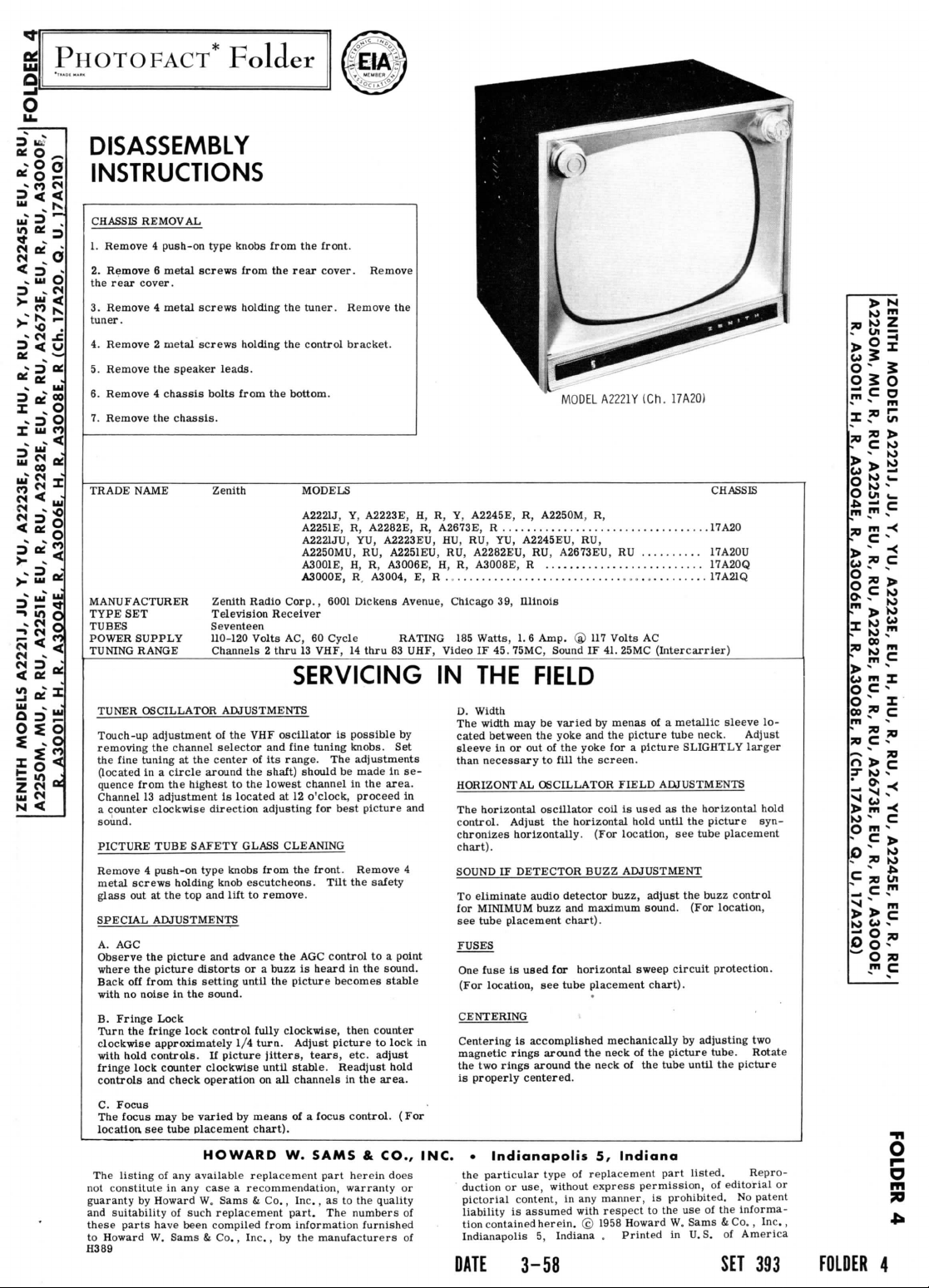
DISASSEMBLY
INSTRUCTIONS
CHASSIS
REMOVAL
1.
Remove 4 push-on type knobs
2.
Remove 6 metal
the
rear
cover.
3.
Remove 4 metal
tuner.
4.
Remove 2 metal screws holding
5.
Remove
6.
Remove 4 chassis
7.
Remove
TRADE
NAME
MANUFACTURER
TYPE
SET
TUBES
POWER
SUPPLY
TUNING
RANGE
the
the
screws
screws
speaker
bolts
chassis.
Television
Seventeen
110-120
Channels 2 thru
Folder
from
from
the
holding
the
the
leads.
from
the
Zenith
Zenith
Radio
Corp.,
Receiver
Volts
AC, 60
the
front.
rear
cover. Remove
tuner. Remove
control bracket.
bottom.
MODELS
A2221J,
Y,
A2251E,
R,
A2221JU,
YU,
A2250MU,
A3001E,
A3000E,
13
RU,
H, R,
R.
6001
Dickens
Cycle RATING
VHF,
14
the
A2223E,
A2282E,
A2223EU,
A2251EU,
A3006E,
A3004,
E, R
Avenue, Chicago
thru
83
UHF, Video
MODEL
A2221YlCh.
H, R, Y,
R,
A2245E,
A2673E, R 17A20
HU, RU, YU,
RU,
A2282EU,
H, R,
17A21Q
185
R,
A2250M,
A2245EU,
A3008E, R 17A20Q
Watts,
IF 45.
RU,
39,
Illinois
1.6
Amp.
75MC, Sound
R,
RU,
A2673EU,
© 117
IF 41.
RU
Volts
17A20)
17A20U
AC
25MC
(Intercarrier)
CHASSIS
TUNER
OSCILLATOR
Touch-up
removing
the
(located
quence
Channel
a
sound.
PICTURE
Remove 4 push-on type knobs
metal
glass
SPECIAL
A.
Observe
where
Back
with
B.
Turn
clockwise approximately
with
fringe
controls
C.
The
location,
The
not
guaranty
and
these parts
to
Howard
H389
adjustment
the
fine
tuning
in a
circle
from
the
13
counter clockwise direction adjusting
constitute
suitability
adjustment
TUBE
screws
out at the top and
ADJUSTMENTS
AGC
the
picture
the
picture
off
from
no
noise
Fringe Lock
the
fringe lock control
hold
controls.
lock counter clockwise until
and
check operation
Focus
focus
may be
see
tube placement chart).
listing
of any
in any
by
Howard
of
have
W.
Sams
ADJUSTMENTS
of the VHF
channel
selector
at the
center
around
highest
SAFETY
holding
and
distorts
this
setting
in the
sound.
If
varied
HOWARD
available replacement part herein does
case a recommendation, warranty
W,
such replacement part.
been compiled
Si
and
of its
the
shaft)
to the
lowest channel
is
located
GLASS
from
knob
escutcheons.
lift
to
remove.
advance
or a
until
fully
1/4
turn.
picture
jitters,
on all
by
means
Sams & Co.,
from
Co.,
Inc.,
SERVICING
oscillator
range.
at 12
CLEANING
the AGC
buzz
the
clockwise,
W.
by the
is
fine
the
picture becomes
Adjust
stable.
channels
of a
Inc.,
information
possible
tuning knobs.
The
should
is
adjustments
be
made
in the
o'clock, proceed
for
best
picture
front. Remove
Tilt
the
control
heard
in the
then
picture
tears,
etc.
Readjust
in the
focus
control.
SAMS & CO., INC.
as to the
The
numbers
furnished
manufacturers
by
Set
in se-
area.
safety
to a
point
sound.
stable
counter
to
lock
adjust
hold
area.
(For
quality
IN THE
D.
The
cated between
sleeve
than
in
and
4
or
of
of
HORIZONTAL
The
control.
chronizes horizontally. (For location,
chart).
SOUND
To
for
see
FUSES
in
the
DATE
FIELD
Width
width
may be
the
in or out of the
necessary
horizontal
eliminate audio
MINIMUM
tube placement
One
fuse
(For
location,
CENTERING
Centering
magnetic
two
is
properly centered.
•
Indianapolis
the
particular
duction
pictorial content,
liability
tion
contained
Indianapolis
3-58
to
OSCILLATOR
oscillator
Adjust
IF
DETECTOR
buzz
is
used
see
is
accomplished mechanically
rings
around
rings
around
type
or
use,
is
assumed
herein. © 1958
5,
varied
by
menas
of a
yoke
and the
yoke
fill
the
for
without
Indiana . Printed
for a
the
screen.
FIELD
coil
is
horizontal hold until
BUZZ
ADJUSTMENT
detector
buzz, adjust
and
maximum sound. (For location,
chart).
horizontal sweep
tube placement chart).
the
neck
the
neck
of the
5,
Indiana
of
replacement part listed. Repro-
express permission,
in any
manner,
with
respect
metallic
picture tube neck.
picture
SLIGHTLY
ADJUSTMENTS
used
as the
the
see
tube placement
the
circuit
by
of the
picture tube. Rotate
tube until
is
prohibited.
to the use of the
Howard
W.
Sams
in
U.S.
sleeve
lo-
Adjust
larger
horizontal hold
picture
syn-
buzz control
protection.
adjusting
the
of
editorial
&Co.,
of
SET
two
picture
No
patent
informa America
393
Inc.,
or
FOLDER
4
o
o
m
70
Page 2
TUNER
VHP
IS-41682
ITOPVIEWI
SCHEMATIC
TUNER PART
\D
ON
PAGE
SWITCH
ON
BI-STABLE
2?
REMOTE
_TRANSFORMER
FOR
CHASSIS
PART
RELAY
CONTROL
PRIMARY]
IS-41941
I7A20Q
5.
21
-i
PQ-1
SOCKET
ON
CONTROLCHASSIS
USED
ON
CHASSIS
REMOTE (ONE
PART
17A21Q
REMOTE WIRING
WAYI
PLUG USED WITH
IS-41940
REMOTE CONTROL
ONLY
CHASSIS
I
MEASURED
6
SEE
VALUE
DC
NOT
ARROWS
WAVEFORMS
SET
PEAK
PAGE
FROM
PIN 7 OF V2.
PARTS
LIST
FOR
OR
COIL
RESISTANCE VALUES
SHOWN
ON
(CONTROL
TO
PRODUCE
SIGNAL
voltmeter;
per
volt.
2. Pin
numbers
bottom
ALTERNATE
APPLICATION
ON
SCHEMATIC DIAGRAM
CONTROLS INDICATE CLOCKWISE
VIEWED FROM SHAFT END)
TAKEN
WITH
50
VOLTS PEAK-TO-
AT
PICTURE
AC
voltage measured
are
counted
of
socket.
2
UNDER
CONTROLS
TUBE.
at
1000
in
clockwise direction
ONE OHM
ohrns
on
ROTATION
3.
Measured
4
Line
5.
All con
Vo
val
taqe
rols
se
stated.
maintained
s
et
for
normal
at 1 17
oper
volts
ation;
pin to
for
no
commor
roltage
signa
negative
read
app
ngs.
ied.
A
PHOTOFACT
STANDARD
Ho»«J
W.
NOTATION
S«ms S Co.,
Inc. 1958
SCHEMATIC
Page 3
ZENITH MODELS A2221J,
A2250M,
R,
A3OO1E,
MU, R, RU,
H, R,
A2251E,
A3OO4E,
TO
CAP OF
(HORIZ.
OUTPUT)
JU, Y, YU,
EU, R, RU,
R,
A3OO6E,
HV
TRANSFORMER
Vll
TERMINAL
A2223E,
EU, H, HU, R, RU, Y, YU,
A2282E,
H, R,
A3OO8E, R (Ch. 17A2O,
LOCATION
EU, R, RU,
A2673E,
A2245E,
EU, R, RU,
O, U,
EU, R, RU,
A3OOOE,
17A21Q)
PAGE
23
Page 4
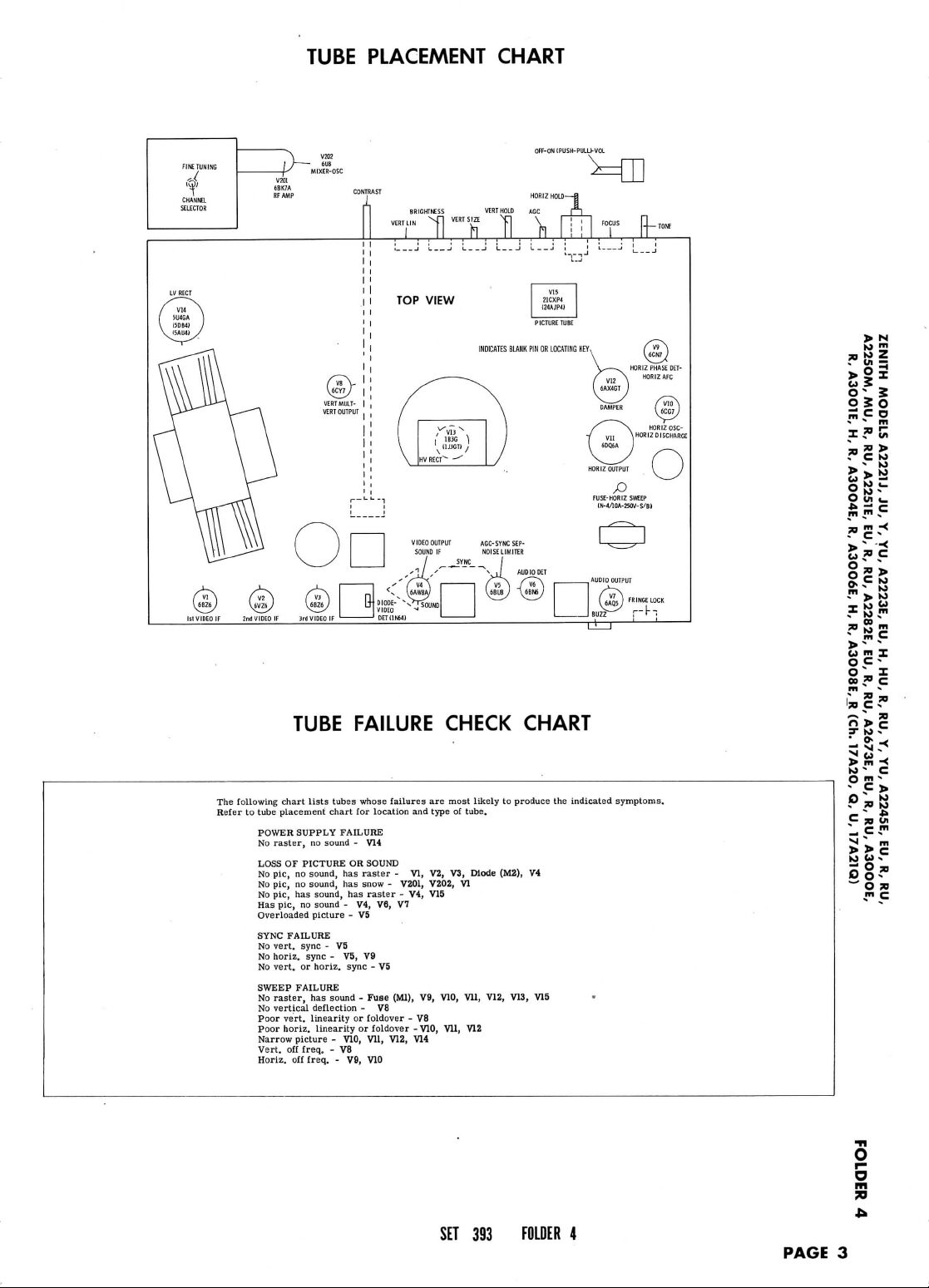
TUBE
PLACEMENT
CHART
OFF-ON
IPUSH-PULU-VOL
> N
0|o^
O u <_
££c
The
following
Refer
to
tube placement
POWER
No
LOSS
No
No
No
Has
Overloaded
SYNC
No
No
No
SWEEP
No
No
Poor
Poor
Narrow picture - V10,
Vert,
Horiz.
TUBE
chart
lists
SUPPLY FAILURE
raster,
no
sound - V14
OF
PICTURE
pic,
no
sound,
pic,
no
sound,
pic,
has
sound,
pic,
no
sound
picture
FAILURE
vert,
sync - V5
horiz.
sync - V5,
vert,
or
horiz.
FAILURE
raster,
has
vertical
deflection
vert,
linearity
horiz.
linearity
off
freq.
- V8
off
freq.
FAILURE CHECK
tubes whose failures
chart
for
location
OR
SOUND
has
raster - VI,
has
snow - V201, V202,
has
raster
- V4, V6, V7
- V5
V9
sync
- V5
sound - Fuse
- V8
or
foldover
or
foldover - V10,
Vll,
- V9,
V10
- V4, V15
(Ml),
V12,
and
V9,
- V8
V14
are
most likely
type
V2,
V3,
V10,
Vll,
of
VI
Vll,
V12
tube.
Mode
CHART
to
produce
(M2),
V12,
V13,
V4
V15
the
indicated
•
symploms.
> M
sa
<•> m X
O
C'
O _ I
00 » C
3- M »
L * -<
-
Cs™
a'*.
m
>
> c
1-
' O »
m
C
SET
393
FOLDER
4
PAGE
3
o
m
JO
Page 5
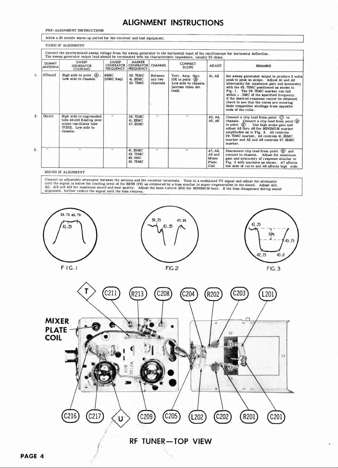
PRE-ALIGNMENT
Allow
a 20
minute
VIDEO
IF
ALIGNMENT
Connect
the
The
DUMMY
ANTENNA
470mmf
Direct
SOUND
Connect
until
All,
alignment,
synchronized sweep
sweep
generator output lead should
High
Low
High
tube
mixer-oscillator
(V202).
chassis.
IF
ALIGNMENT
an
adjustable attenuator between
the
signal
A12
and
further reduce
INSTRUCTIONS
warm-up period
SWEEP
GENERATOR
COUPLING
side
to
side
to
side
to
shield
floating
Low
is
below
A13
for
maximum sound
point
^>
chassis.
ungrounded
over
tube
side
to
the
limiting
the
signal until
for the
voltage
GENERATOR
FREQUENCY
.
44MC
(10MC
level
ALIGNMENT
receiver
and
from
the
sweep
be
terminated with
SWEEP
GENERATOR
FREQUENCY
39.
Swp)
41.25MC
45.
39.75MC
41.
47.
41.25MC
42.
45.0MC
45.75MC
the
antenna
of the
and
6BN6
best
quality. Adjust
the
hiss
returns.
test
generator
MARKER
75MC
75MC
25MC
25MC
75MC
and the
(V6)
equipment.
to the
its
characteristic
CHANNEL
Between
any two
channels
receiver
as
evidenced
the
buzz control
INSTRUCTIONS
horizontal input
impedance, usually
Vert.
10K
Low
(across
load).
terminals.
by a
hiss
CONNECT
SCOPE
Amp. thru
to
point
side
to
video
Tune
similar
(Rll)
for
of the
oscilloscope
50
ADJUST
<g>
chassis,
Al,
.
det.
A3, A4,
A5, A6
A7,
A9
Mixer
Plate
Coil
in a
modulated
to
super-regeneration
MINIMUM
buzz.
ohms.
A2
A8,
and
TV
for
horizontal
Set
sweep
peak
to
alternately
with
the 45.
Fig. 1 .
within
if
the
desired
check
their
respective
ends
of the
Connect a clip
chassis.
to
point
adjust
amplitudes
39.
75MC
marker
marker.
Disconnect clip
connect
gain
and
Fig. 3 with
low
side
signal
in the
If the
hiss
deflection.
generator
peak
on
scope.
for
maximum gain
75MC
The
39.
± .
SMC
of the
response
to see
that
coils.
lead
Connect a clip
<E>
. Use
A3
thru
A6 for
as in
marker,
and A5 and A6
lead
to
chassis.
symmetry
markers
of
curve
and
adjust
sound.
disappears
REMARKS
output
Adjust
positioned
75MC
marker
specified
the
cores
windings
from point
high
MINIMUM
Fig.
2. A3
A4
controls
controls
from point
Adjust
of
response
as
and A8
the
attenuator
Adjust
during sound
to
cannot
are
from
lead
scope
for
shown.
affects
A10,
as
from
controls
produce 3 volts
Al and A2
and
symmetry
shown
in
can
fall
frequency.
be
obtained,
entering
opposite
<£>
to
point
<§>
gain
and
marker
41.
25MC
47.
25MC
<£)
and
maximum
similar
to
A7
affects
high
side.
F
MIXER
PLATE
COIL
Nl
IG.I
*S*
FIG.
RF
TUNER-TOP
2
VIEW
FIG.
3
PAGE
4
Page 6

MIXER
PLATE
CO
IL
IF
OUTPUT
RFAGC
*
MEASURED
A
PHOTOFACT STANDARD
FROM
How,,d
PIN
VC.
3 OF
S.m, & Co.,
V201.
NOTATION
Inc. 1958
CHANNEL SELECTOR SWITCH SHOWN
SCHEMATIC
(DLCtfZl
'aoooEV
'na
'a
'na
'ns
'n 'D
'a
'ni
'ssfrctv
'OZWZl
TUNER
'3E/9tv
'nx
'A
IN
CHANNEL
VHP
TUNER
PAR!
IS-41682
SCHEMATIC
'MD) U '38OOEW
'na
'a
'03
'OH
'scatcw
'H
'03
'na
'a
13
POSITION
'«
'H
'SEECCW
'39OOEW
'na
'a
'ns
'HA
'M
'IfrOOEV
'3isicw
'A
'nr
'a
'na
'rictzw
'H
'31OOCV
'a
'nw
sisaow
"S
'wosctw
Page 7
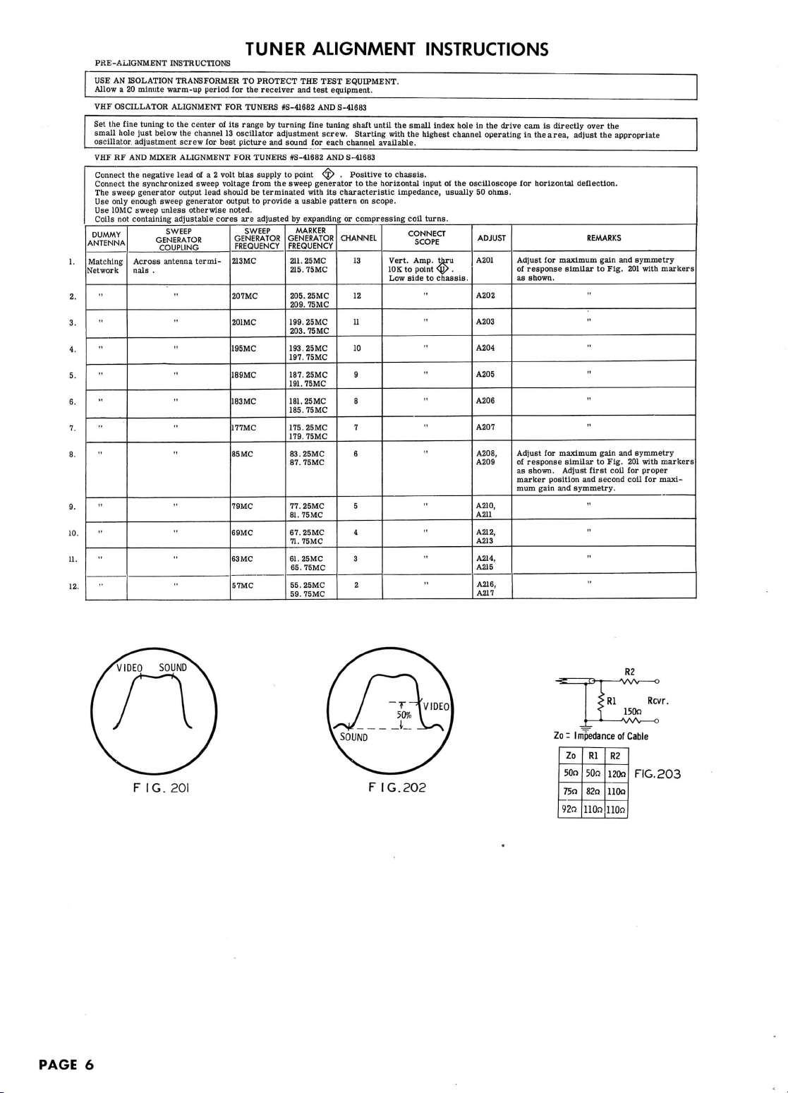
PHE-ALIGNMENT
USE
AN
ISOLATION TRANSFORMER
Allow
a 20
minute
VHF
OSCILLATOR ALIGNMENT
Set the
fine
hole
adjustment
RF AND
Connect
the
the
sweep
only
enough
10MC
not
containing adjustable
tuning
just
below
MIXER ALIGNMENT
negative
synchronized sweep
generator
sweep
sweep
unless
GENERATOR
COUPLING
Across
antenna
nals
.
small
oscillator,
VHF
Connect
The
Use
Use
Coils
DUMMY
ANTENNA
Matching
Network
"
-
"
-
INSTRUCTIONS
warm-up
period
to the
center
the
channel
screw
for
lead
of a 2
output lead should
generator
otherwise noted.
SWEEP
cores
termi-
"
"
for the
FOR
of its
13
best
FOR
volt
voltage
output
213MC
207MC
201MC
195MC
18SMC
I83MC
177MC
85MC
79MC
69MC
63
57MC
TUNER
TO
PROTECT
receiver
TUNERS
range
by
oscillator
picture
and
TUNERS
bias
supply
from
the
be
terminated
to
provide a usable
are
adjusted
SWEEP
GENERATOR
FREQUENCY
MC
ALIGNMENT
THE
TEST
and
test
equipment.
#3-41682
AND
S-41683
turning
fine
sound
for
#S-41682
to
point
sweep
with
by
expanding
MARKER
GENERATOR
FREQUENCY
211.
25MC
215.75MC
205.25MC
209. 75MC
199.25MC
203.75MC
193.25MC
197. 75MC
187. 25MC
191. 75MC
181.25MC
185.75MC
175.25MC
179.
75MC
83.25MC
87.
75MC
77.25MC
81.
75 MC
67.25MC
71.
75MC
61.25MC
65.
75MC
55.25MC
59.
75MC
tuning shaft
screw.
each channel
AND
\£> , Positive
generator
its
characteristic
pattern
adjustment
EQUIPMENT.
until
Starting
available.
S-41683
to
to the
horizontal
on
scope.
or
compressing
CHANNEL
13
12
11
10
9
8
7
6
5
4
3
2
INSTRUCTIONS
the
small
index
hole
of the
usually
thru
<§>
.
chassis.
in the
oscilloscope
50
ADJUST
A201
A202
A203
A204
A205
A206
A207
A208,
A209
A210,
A211
A212,
A213
A214,
A215
A216,
A217
with
the
chassis.
impedance,
coil
CONNECT
Vert.
Amp.
10K
to
Low
side
highest channel
input
turns.
SCOPE
point
to
"
"
"
drive
operating
ohms.
cam is
directly
in the
area,
adjust
for
horizontal
deflection.
Adjust
for
maximum
of
response
as
Adjust
of
as
marker
mum
similar
shown.
for
maximum
response
similar
shown. Adjust first
position
gain
and
symmetry.
over
REMARKS
"
to
and
"
"
the
the
appropriate
gain
to
Fig.
gain
Fig,
coil
second
and
and
201
201
for
coil
symmetry
with
markers
symmetry
with
markers
proper
for
maxi-
PAGE
6
F
IG.
201
FIG.202
Rl
Rcvr.
150n
FIG.
203
Page 8
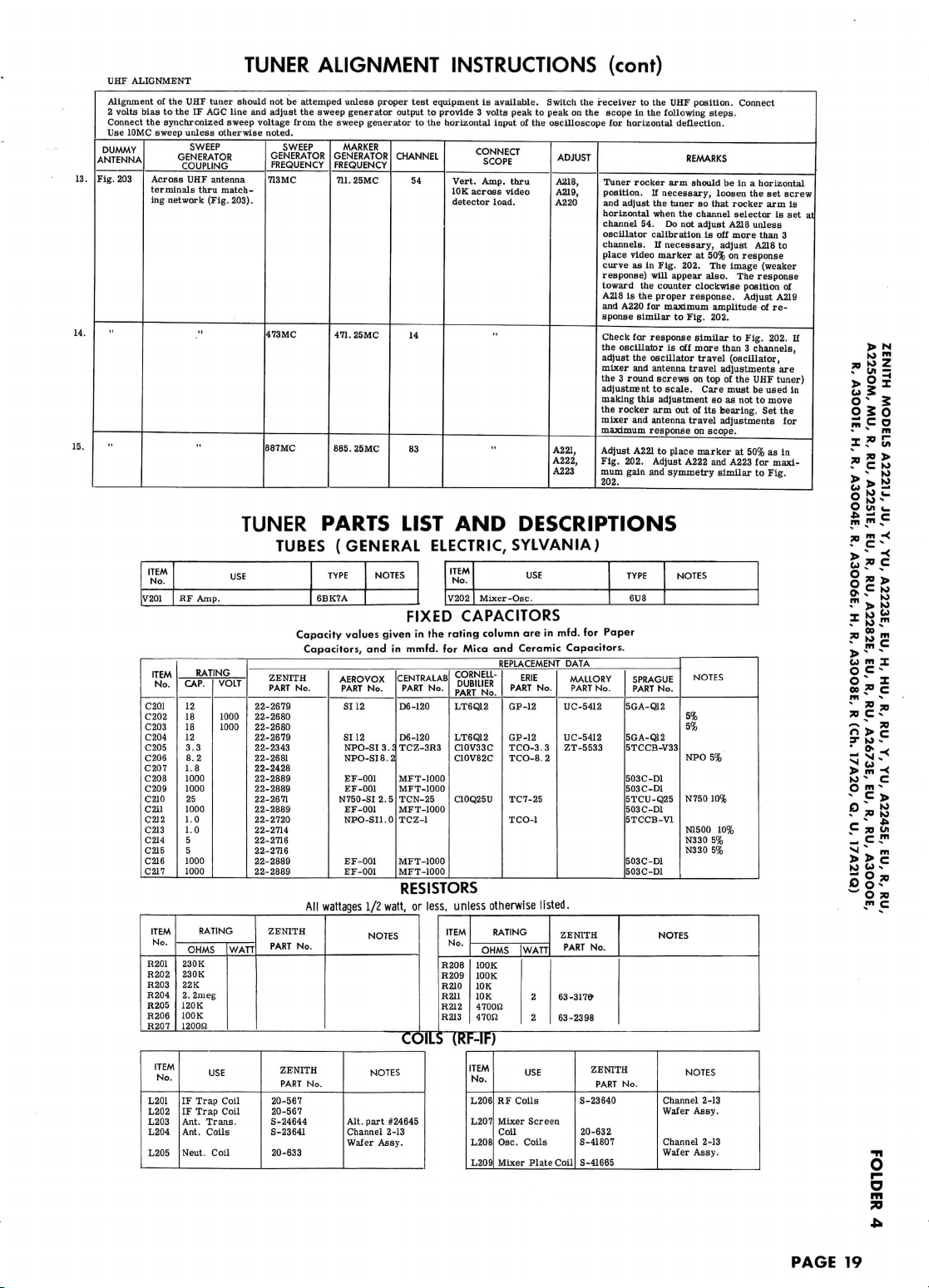
UHF
ALIGNMENT
Alignment
2
volts
Connect
Use
10MC sweep
DUMMY
ANTENNA
Fig.
203
of the UHF
bias
to the IF AGC
the
synchronized
Across
terminals
ing
network
tuner should
unless
otherwise noted.
SWEEP
GENERATOR
COUPLING
UHF
antenna
thru
match-
(Fig. 203).
TUNER
not be
line
and
adjust
sweep voltage
GENERATOR
FREQUENCY
713MC
473MC
887MC
ALIGNMENT
artemped
unless
the
from
SWEEP
sweep
the
proper
generator
sweep generator
MARKER
GENERATOR
FREQUENCY
711.
25MC
471.
25MC
885.25MC
test
output
to the
CHANNEL
54
14
83
INSTRUCTIONS
equipment
to
is
horizontal
CONNECT
Vert.
Amp.
10K
across
detector
available.
input
SCOPE
load.
provide 3 volts
peak
thru
video
of the
Switch
to
peak
the
on the
oscilloscope
ADJUST
A218,
A219,
A220
A221,
A222,
A223
(cont)
receiver
to the UHF
scope
in the
for
horizontal deflection.
Tuner
rocker
position.
and
adjust
horizontal
channel
54. Do not
oscillator
channels.
place
video
curve
as in
response)
toward
the
A218
is the
and
A220 for maximum amplitude of re-
sponse
similar
Check
for
the
oscillator
adjust
the
mixer
and
the 3 round
adjustment
making
this
the
rocker
mixer
and
maximum
Adjust
A221
Fig. 202. Adjust
mum
gain
202.
position.
following
steps.
REMARKS
arm
should
If
necessary,
the
tuner
when
calibration
If
necessary,
marker
Fig. 202.
will
appear
counter clockwise position
proper
response
is off
oscillator
antenna
screws
to
scale.
adjustment
arm out of its
antenna
response
to
place
and
symmetry
be in a
loosen
so
that
the
channel
adjust
A218
is off
adjust
at 50% on
The
also.
response.
to
Fig. 202.
similar
more
than 3 channels,
travel
travel
adjustments
on top of the UHF
Care
must
so as not to
bearing.
travel
adjustments
on
scope.
marker
A222
and
similar
(oscillator,
Connect
horizontal
the set
arm is
is
unless
A218
to
response
response
Adjust
A219
Fig. 202.
are
tuner)
be
used
move
Set the
for
at 50% as in
for
maxi-
to
Fig.
screw
3
of
rocker
selector
more than
image (weaker
The
to
A223
set at
If
in
>
10
o 2 o
ITEM
V201
C201
C202
C203
C204
C205
C206
C207
C208
C209
C210
C211
C212
C213
C214
C215
C216
C217
No.
ITEM
No.
ITEM
No.
R201
R202
R203
R204
R205
R206
R207
ITEM
L201
L202
L203
L204
L205
TUNER
USE
RF
Amp.
RATING
VOLT
CAP.
12
18
1000
1000
18
12
3.3
8.2
1.8
1000
1000
25
1000
1.0
1.0
5
5
1000
1000
RATING
OHMS
230K
230K
22K
2.
2meg
120K
100
K
1200S2
No
IF
Trap Coil
IF
Trap
Ant.
Trans.
Ant.
Coils
Neut.
USE
Coil
Coil
WATT
22-2679
22-2343
22-2681
22-2428
22-2889
22-2889
22-2671
22-2889
22-2720
22-2714
22-2716
22-2716
22-2889
22-2889
TUBES
ZENITH
PART
22-2679
22-2680
22-2680
ZENITH
PART
20-567
20-567
S-24644
S-23641
20-633
PARTS
(GENERAL
TYPE
6BK7A
Capacity
Capacitors,
No.
All
wattages
No.
ZENITH
PART
No.
NOTES
values
given
and in
AEROVOX
PART
No.
SI 12
SI 12
NPO-SI 3 .
NPO-SI8.2
EF-001
EF-001
N750-SI2.5
EF-001
NPO-SI1.0
EF-001
EF-001
1/2
NOTES
NOTES
Alt.
part
Channel
Wafer
Assy.
LIST
ELECTRIC,
FIXED
in the
mmfd.
CENTRALAB
PART
No.
D6-120
D6-120
TCZ-3R3
:
MFT-1000
MFT-1000
TCN-25
MFT-1000
TCZ-1
MFT-1000
MFT-1000
RESISTORS
watt,
or
less,
COILS
#24645
2-13
AND
DESCRIPTIONS
SYLVANIA)
ITEM
No.
V202
Mixer
-Osc.
CAPACITORS
rating
column
and
REPLACEMENT
No.
otherwise
RATING
OHMS
100K
100K
10K
10K
4700S2
470J2
are in
Ceramic
ERIE
PART
GP-12
GP-12
TCO-3.3
TCO-8.2
TC7-25
TCO-1
for
unless
ITEM
No.
R208
R209
R210
R211
R212
R213
Mica
CORNELL-
DUBILIER
PART
LT6Q12
LT6Q12
C10V33C
C10V82C
C10Q25U
(RF-IF)
ITEM
No.
HF
Coils
L206
Mixer Screen
L207
Coil
Osc.
Coils
L208
Mixer
L209
USE
No.
listed.
WATT
2
2
USE
Plate
mfd.
for
Capacitors.
DATA
MALLORY
PART
No.
UC-5412
UC-5412
ZT-5533
ZENITH
PART
No.
63-317»
63-2398
ZENITH
PART
S-23640
20-632
S-41807
S-41665
Coil
Paper
No.
TYPE
6U8
SPRAGUE
PART
No.
5GA-Q12
5GA-Q12
5TCCB-V33
503C-D1
503C-D1
5TCU-Q25
503C-D1
5TCCB-V1
503C-D1
503C-D1
NOTES
Channel
Wafer
Channel
Wafer
NOTES
NOTES
5%
5%
NPO 5%
N750
N1500
N330
N330
NOTES
Assy.
Assy.
10%
5%
5%
2-13
2-13
10%
m
-<
BB
*"
*
U
m X
o c
-
o _ z
CO » C
SS-"
PAGE
19
1
73
Page 9

TUNER-LEFT SIDE
PAGE
2O
TUNER-RIGHT
SIDE
Page 10

MIXER
A
6U8
MIXER
PLATE
COIL
A
PHOTOFACT
STANDARD
How.rJW.
NOTATION
S.m,aCo.,lne.
SCHEMATIC
1958
(DIEtf/L
'3OOOCV
'na
'a
'ns
ALTERNATE
'0
'O
'a
'ns
'isfrttw
'OtV/l
'na
'H3) a '38OOEV
'3C/9cw
'nA
'A
'na
CHANNEL
SELECTOR
UHF-VHF TUNER SCHEMATIC
'a
'H
'na
'a
'a
'nn
'ni
'H
'IEBZCV
'na
'aeczcv
'39OOEV
'na
'a
'nA
'M
'n3
'A
'3frOOCV
'aisccv
'nr
Tictcv
'«
'na
N1500
I.lmmf
SWITCH SHOWN
'H
'31OOEW
'a
'nw
siiaow
'M
'woszcv
IN
CHANNEL
13
POSITION
Page 11

PRE-ALIGNMENT
USE
AN
ISOLATION TRANSFORMER
Allow
a 20
minute
VHF
OSCILLATOR
Set
the
fine
tuning
Adjust
for
best
picture
VHF
RF AND
MIXER
Connect
negative
Connect
the
Use
Use
DUMMY
ANTENNA
Fig.
UHF
Alignment
Connect 2 volts
Connect
Use
DUMMY
ANTENNA
synchronized sweep voltage from
only
enough
10MC sweep
203
ALIGNMENT
10MC
Fig:
203
sweep generator output
unless
Across antenna
nals matching network
(Fig. 203).
of the UHF
bias
the
synchronized sweep voltage from
sweep
Across
terminals thru matching
network (Fig. 203).
'
ALTERNATE
INSTRUCTIONS
warm-up period
ALIGNMENT
at the
and
ALIGNMENT
lead
of
SWEEP
GENERATOR
COUPLING
tuner should
to the IF AGC
unless otherwise noted.
SWEEP
GENERATOR
COUPLING
UHF
antenna
for the
FOR
center
of its
range.
sound.
___
FOR
0-15 volt
variable
otherwise
noted.
GENERATOR
FREQUENCY
termi-
195MC
213MC
207MC
201MC
195MC
189MC
183MC
177MC
85MC
79MC
69MC
63MC
57MC
not be
line
GENERATOR
FREQUENCY
713MC
473MC
887MC
TUNER
TO
PROTECT
THE
receiver
and
test
TUNERS
#3-41692
The
adjustments
TUNERS
#3-41692
bias
supply
to
the
sweep generator
to
provide a usable
SWEEP
and
SWEEP
MARKER
GENERATOR
FREQUENCY
193.25MC
197.75MC
211.25MC
21S.75MC
205.
25 MC
209. 75MC
199.
25MC
203.
75MC
193.25MC
197.
75MC
187.
25MC
191.
75MC
181. 25MC
185.75MC
175.25MC
179.
75MC
83.25MC
87.
75MC
77.
25MC
81.
75MC
67.25MC
71.
75MC
61.
25MC
65.75MC
55.25MC
59.
75MC
attempted unless proper
adjust
the
sweep
the
sweep
generator
MARKER
GENERATOR
FREQUENCY
711.25MC
471.25MC
885.25MC
ALIGNMENT INSTRUCTIONS
TEST EQUIPMENT.
equipment.
AND
S-41693
are
AND
S-41693
point
^> . Positive
to the
pattern
CHANNEL
generator
CHANNEL
accessible,
on
10
13
12
11
10
9
8
7
6
5
4
3
2
test
to the
54
14
83
one at a
to
horizontal input
scope.
CONNECT
Vert.
Amp. thru
10K
to
Low
side
equipment
output
to
provide 3 volts
horizontal
CONNECT
Vert.
Amp.
10K
across
detector
time,
chassis.
SCOPE
point
<g>
to
chassis.
is
available.
input
SCOPE
video
load.
of the
of the
thru
as the
Adjust
oscilloscope
A202,
.
A203
A204
A206
A207
A208
A209
A210
A211
A212
A213
A214
A215
Switch
peak
oscilloscope
channel
bias
ADJUST
A201,
A205
the
to
ADJUST
A216,
A217,
A218
A219,
A220,
A221
selector
for 2. 5
for
Adjust
tude
in
amplitude
changing
MINIMUM
Adjust
similar
or
receiver
peak
for
Tuner
position.
and
horizontal
channel
lator
If
marker
202.
appear
ter
response.
mum
202.
Check
the
adjust
mixer
tne 3 round
adjustment
making
rocker
and
response
Adjust
Fig. 202.
mum
202.
is
rotated.
volts
at
point
horizontal deflection.
A201
and
Fig. 201.
for
compressing
on the
horizontal deflection.
rocker
adjust
calibration
necessary,
The
also.
clockwise position
amplitude
for
oscillator
the
and
arm out of its
antenna
A219
gain
<£>
REMARKS
and
A202
symmetry
Increase
of
response
the
bias
adjust A203
response
maximum amplitude
to
Fig. 201. Adjust
coil
to the UHF
scope
in the
arm
If
necessary,
the
tuner
when
the
54. Do not
is
adjust
at 50% on
image (weaker response)
The
Adjust
A217
of
response
is off
oscillator
antenna
screws
to
scale.
this
adjustment
travel
on
scope.
to
place
Adjust
A220
and
symmetry
.
for
maximum
with
markers
bias
for
MINIMUM
curve. Without
to
on the
turns.
position.
following
REMARKS
should
so
channel
adjust
off
A216
response
response
response
similar
more
travel
travel
on top of the UHF
Care
bearing.
adjustments
marker
obtain
scope.
of
by
expanding
steps.
be in a
loosen
the set
that
rocker
selector
A216
unless
more
than 3 channels.
to
place video
curve
toward
of
A216
is the
and
A218
similar
to
Fig. 202.
than 3 channels,
(oscillator,
adjustments
must
so as not to
Set the
for
at 50% as in
and
A221
similar
ampli-
as
shown
response
horizontal
screw
arm
is set at
oscil-
as in
will
the
coun-
proper
for
maxi to
Fig.
are
tuner)
be
used
move
mixer
maximum
for
maxi-
to
Fig.
Is
Fig.
If
in
the
PAGE
8
F
IG.20I
FIG.202
Rl
Rcvr.
150n
FIG.
203
Page 12

VHFANT.
TERMINAL
BOARD
MIXER
A
6CG8
IF
OUTPUT
FILAMENT
A
PHOTOFACT
STANDARD
Howird
W.
NOTATION
Sim, & Co.,
Inc.
SCHEMATIC
1958
'3OOOEV
'na
ALTERNATE
(oizwzi
'a
'na
'na
'as^ccv
'n
'a
'o
'ocv/i
'n3
-HD) a 'aeoocv
'3CZ9ZW
'nx
'A
'na
UHF-VHF TUNER SCHEMATIC
'a
'H
'na
'a
'a
'nH
'na
'ataczv
'H
'na
'sezctv
'39ooev
'na
'a
'nx
'a
'n3
'A
'a»oocw
'3isczv
'nr
'rittcv
'a
'na
'H
'aioocv
'a
'nw
siaaow
'a
'wosctw
HIINSZ
Page 13

•a
O
m
00
VHFANT.
TERMINAL
BOARD
. — ,
£*•
»-/7OTT>> — t — = — !
^ML>
'Wi
JT
(mj
}
W-
120m
30mmf
'
mf
\\/s-
fl
i , i
[A204]THRu[A215j
r
!
5
i
AV
)(•
«.<:>
^W>
12mmf
!
i
i
„
i
/\
iM A / V V
:28mmf " V*
>
<^
o
o
1
J
1
<p^— r '--^---^ — •
A
A
i\
6BN4
.
>
J
1
RF
XTN
\
1-6
Ps
5.0-10J7
mmf
~
if
,
Hi
1
'
|A203|
4700n
*—*
SOOmmf
AMP
A,\\
1.0-4.5
mmf
|A20l|^
47mmf
*"T*"
_-J—
SOOmmf
=^
I
<
<
72V
y
4
|
>
I'"
Wv",/
Y
13
°
§
—
'
10000
R
X^i
-* ^ "
b
1
"
!'J5~^*
l§
1 o N750
1
«KER
A
—
it
47mmf ! gfr^
J[A202J
T1-0-4/5
6»
mmf
^^
±2^
-L
I
-2-7V
T
9\F^!
|3900n
30m;.
—
|
1
^
FINE
T
N330
6.8mmf
3.ommf
NPO
6CG8
/r==--^y_
JT
^
o/ll\_
220K
fc
F
osc
B6CG8
TUNING
1
2|WV
r'TN
f^Ax
^"
_L
5
UK
=•
SOOmmf
J25V
,ici/
^
i
>
>
S
^lOOOmmf
4r
10K
MIXER
1
PLATE
V
g
^>
<
r
\
SOOmmf
J
COIL
IF
OUTPUT
•
A
PHOTOFACT STANDARD
Howard
W.
Sams
NOTATION
& C
o.,
Inc. 1958
SCHEMATIC
ALTERNATE
VHP
VHF
TUNER
PART
TUNER
>
6800n
IS-41692
SCHEMATIC
S5600n7W
]
1
1
i i *
If?
T"
275V,,
X , T
»|
9
l?l
T
H)
RFAGC
~
FILAMENT
Page 14
'AGE
16
Page 15

tr
aacnod
CHASSIS
BOTTOM VIEW-CAPACITOR
(OLttf/L
'3OOOCV
'na
'a
'na
'n3
'0
'D
'a
'n3
'3s*ctw
'OCWZl
'3e/9cv
'iu
'A
'MD) a '38OOEW
'na
'a
'03
'OH
'izvtiv
'H
'na
'a
'03
AND
'a
'H
'39OOCV
'na
'3ect5W
ALIGNMENT
'a
'a
'nx
'ns
'A
'3frOOeV
aisitv
'nr
'«
'na
Tictcv
'H
IDENTIFICATION
'3LOOCV
'a
'nw
siaaow
'a
'wosctv
Page 16

'AGE
1O
Page 17

aacnod
CHASSIS
BOTTOM
(DltW/L
'3OOOCV
'na
'a
'fia
'03
'0
'ssfricw
VIEW-RESISTOR
'O
'OCV/l
'MS)
Ji
'a
'03
'3C^9cw
'ru
'*
'na
'na
'a
'380OCV
'a
'ns
'nn
'a
'3S8C5V
'H
'ns
AND
'H
'39OOCV
'na
'acctcw
INDUCTOR
'a
'a
'nx
'na
'A
'3frOOCV
'aisccv
'nr
'H
'na
Tizccw
IDENTIFICATION
'H
'310OCV
'a
'nw
si3aow
'a
'wosccv
Page 18

CENTERING
WIDTH
SLEEVE
CABINET-REAR
VIEW
BUZZ
FRINGE
LOCK
>i
u
5
o-
5
03
o
».C
O
in
«_
•H m -<
•5
"
5 » c
'
O-
^
"^
^
> m
-<
•0s
C
O ™ -
•
C >
Turn
the set on and
Set
the
brightness
Turn
the
horizontal hold clockwise
tune
in a TV
and
contrast controls
HORIZONTAL
station, preferably
for a
until
the
with a test
normal picture.
picture
loses
sync.
SWEEP CIRCUIT ADJUSTMENTS
be
necessary
to
switch
otf
channel
and
pattern.
It may
SET
sync.
Turn
falls
393
the
horizontal hold slowly counter clockwise until
into
sync.
FOLDER
4
back again
for
picture
the
to
lose
picture just
PAGE
11
O
jo
me
5
Page 19

ITEM
VI
V2
V3
V4
V5
V6
V7
ITEM
No.
V15
ITEM
No.
CIA
C2A
ITEM
No.
C3
C4
C5
C6
C7
C8
C9
do
Cll
C12
as
C14
CIS
C16
07
as
C19
C20
C21
C22
C23
C24
C25
C26
C27
C26
C29
C30
C31
C32
C33A
C34
C35
C36
C37
C38
C39
C40
C41
C42
C43
C44
C45
C46
C47A
C48
C49
C50
C51
C52
C53
C54
C55
C56
C57A
C58
C59
C60
C61
C62
)
D
No.
B
C
D
B
C
B
B
B
Some
Some
1st. Video
2nd.
Video
3rd. Video
Video
Output-Sound
AGC - Sync
Noise
Audio
Audio Output
ZENITH
PART
No.
21CXP4
24AJP4
RATING
CAP.
VOLT.
•40
.80
.10
476
100
350
14
400
•10
20
25
RATING
CAP.
470
6
1000
12
12
7
470
1.5
1000
1000
1000
470
330
470
5
7.5
4700
47
.1
.1
10000
1000
10000
.33
3.3
50
2.4
470
4
10
\
1000'
1000470
10000
2200
2200
470
3300
.15
.022
.0068
.015
.1
.047
.033
100
-
\
100 _
4700
4700
1000
.047
.1
330
1100
1500
1000
1000"
\0
1000.
4700
.1
10000
110
72
versions
versions
USE
IF
IF
IF
Limiter
Det.
400
400
50
VOLT
1000
1000
1000
1000
1000
200
200
1000
200
1000
iOOO
1000
200
200
400
600
400
200
400
200
200
1000
4000
2000
use 7.
use .
Amp.
Amp.
Amp.
Sep.
GENERAL
22-2971
22-2744
22-6
22-2381
22-17
22-2379
22-2379
22-2513
22-16
22-1764
22-17
22-17
22-17
22-16
22-2667
22-16
22-2990
22-2742
22-14
22-2467
22-1777
22-1777
22-3
22-17
22-3
22-2159
22-2343
22-2460
22-2596
22-2460
22-2731
22-21
22-6
22-3
22-8
22-8
22-6
22-11
22-2147
22-2621
22-2264
22-2061
22-1778
22-2635
22-22
22-14
22-17
22-1778
22-1777
22-2667
22-2859
22-12
22-17
22-21
22-14
22-1841
22-3
22-2694
5mmf
Olmfd
TUBES
IF Amp
-
PART
ZENITH
PART
No.
ZENITH
PART
/
(Part
gi
(GENERAL
TYPE
6BZ6
6BZ6
6BZ6
6AW8A
6BU8
6BN6
6AQ5
REPIACEMENT
ELECTRIC
No.
ELECTROLYTIC
AFH4-113-50
AFH3-180
Capacity
values
Capacitors,
AEROVOX
No.
PART
HVD-15-470
NPO-SI1.5
1469-00033
P288N-1
P288N-1
BPD-01
HVD-15-1000
BPD-01
P288N-33
NPO-SI3.3
SI 50
HVD-15-470
BPD-01
BPD-0022
BPD-0022
HVD-15-470
BPD-0033
P288N-15
P488N-1
P288N-047
BPD-0001
\4
BPD-0001
P288N-1
1469-08033
1464-0011
P688N-1
BPD-01
#22-2742)
200V
10%
NOTES
PICTURE
DATA
RCA
PART
AEROVOX
PART
No.
given
and in
No.
In
this
(Part
#22-2565)
ELECTRIC,
No.
CORNELL-
DUBILIER
PART
,
C1445.3
-BR8045
C1445
FIXED
in the
mmfd.
CENTRALAB
PART
No.
DD-471
D6-471
TCZ-1R5
D6-471
D6-331
D6-471
TCN-47
DF-104
DF-104
DD-103
DD-102
DD-103
TCZ-3R3
D6-500
DD-103
DD-222
DD-222
D6-471
DD-332
DF-104
DF-503
DD-101
DD-101
DF-104
D6-331
DD-103
application.
in
TUBE
SYLVANIA)
ITEM
No.
V8
Vert.
Mult.
V9
Horiz.
Phase
Horiz.
Horiz.
Horiz.
Damper
HV
LV
«
Used
SYLVANPA
PART
No.
(D
AFC
Osc.-Horlz.
Output
Rectifier
Rectifier
in
Ch.
V10
VU
V12
V13
V14
21CXP4
CAPACITORS
REPLACEMENT
No.
MALLORY
PART
rFP459
LTCSO
JP394
hrc22
DATA
No.
CAPACITORS
rating
column
and
No.
are in
Ceramic
REPLACEMENT
ERIE
PART
HD15-470
ED-470
TCO-1.5
ED-470
ED-330
ED-470
TC7-47
ED-01
HD15-100(
ED-01
TCO-3.3
GP-50
ED-1000
ED-1000
HD15-470
ED-01
ED-0022
ED-0022
HD15-470
ED-0033
ED-100
ED-100
ED-1000
ED-330
CY20C112J
ED-1500
ED-1000
ED-1000
ED-01
for
Mica
CORNELL-
DUBILIER
PART
BYA10T47
C10V6C
OOV7C
5R5T47
C10V15C
5R5T47
5R5T33
5R5T47
1R5D47
CUB2P1
CTB2P1
BYA6S1
BYA10D1M
BYA6S1
CUB2P33
C10V33C
LT6Q5
C10V4C
"1R5D1
/
\1
-LR5D1
BYA10T47
BYA6S1
BYA10D22
BYA10D22
BYA10T47
BYA10D33
CUB2P15
CUB4P1
CUB2S47
L10T1
L10T1
1R5D47
1H5D47
1R5D1
CUB2P1
5H5T33
1H5D11
1R5D15
"1R5D1
1
\4
-1R5D1
1R5D47
CUB6P1
BYA6S1
this
application.
USE
-Vert.
Det.
CD
No.
17A21Q.
"Silver
PYRAMID
PART
Output
Disch.
NOTES
Screen
No.
mfd.
for
Paper
Capacitors.
DATA
MALLORY
PART
No.
DC30347
GEM-201
GEM-201
DC511
DC3021
DC5U
GEM-2033
ZT-5533
UC-545
MCB255
MCB255
DC30347
DC511
UC-5222
UC-5222
DC30347
UC-5233
GEM-2015
GEM-16268
GEM-401
GEM-4147
UC-531
UC-531
MCB255
GEM-201
MCB255
MCB255
GEM-601
DC511
TYPE
6CY7
6CN7
6CG7
6BQ6A
6AX4GT
1B3GT
5U4GA
85"
SANGAMO
PART
No.
,Q-046
4HTD-4520
T-610
SPRAGUE
PART
5GA-T47
MS-347
5TCCB-W
MS-347
MS-333
MS-347
MS-247
2TM-P1
2TM-P1
5HK-S1
5GA-D1
5HK-S1
2TM-P33
5TCCB-V3!
5GA-Q5
5GA-D1
5GA-D1
5GA-T47
5HK-S1
5GA-D22
5GA-D22
5GA-T47
5GA-D33
2TM-P15
4TM-P1
2TM-S47
5GA-T1
5GA-T1
MS-247
MS-247
MS-21
2TM-P1
MS-333
MS-211
MS-215
MS-21
MS-21
MS-247
6TM-P1
5HK-S1
No.
NOTES
1J3GT
*
5DB4»
5AU4
>
SPRAGUE
PART
No.
*R2584
TVL-3806.
NOTES
NPO
10%
N76 5%
N75 5%
NPO
10%
10%
10%
10%
10%
10%
10%
N470
10%
N750
5%
5%
10%
NPO©
N150
5%
10%
10%
10%
10%
®
10%
a
10%
10%
10%
10%
10%
10%
10%
10%
10%
10%
10%
10%
10%
10%
R1A
R2A
R3A
R4A
,
B
IR5A
R6A
R7A
R8A
R9A
RIGA
Rll
Note
* Use
t
File
tt
ITEM
No.
B
C
B
B
B
B
B
Use
B
B
B
1.
KR-1
double
Imeg
RATING
RESIST-
ANCE
Imeg
Shall
Switch
Imeg
Shaft
750K
Shaft
250K
Shaft
8000!!
Shaft
7.
5meg
Shaft
750K
Shaft
7.5meg
Shaft
aooon
Shaft
5meg
Shaft
750O
Alternate
on red
flat as
resistor
WATTS
i
1
a
~z
2{WW)
1
i
i
4
2
2(WW)
3meg
label
required.
control
In
series
ZENITH
PART
63-4005
63-3616
63-3299
63-3572
83-4001,
63-2919
63-3262
63-3263
63-3568
63-4012
63-3284
control.
PARTS
No.
(part
with
B-70
Not
KB-1
B-70
Not
B-66
Not
B-50
Not
WW-752
Not
AB-B'J
AK-1
AB-66
AK-1
AB-89
AK-1
AB-8
AK-1
#63-4026)
right
hand
LIST
CENTRALAB
PART
No.
Req..
*
Req.
Req.
Req.
t
Req.
tt
may be
terminal
A
REPLACEMEI
CLARO
PART
A47-lm
FS-3
SWE-12
A47-lm
KSS-3
A47-75'
KSS-3
A47-25I
KSS-3
A43-75I
DFS-i/
A47-7.
FKS-1/
A47-75I
FKS-1/'
A47-7.
FKS-1/
A47-30I
FKS-1/'
39-800
used
of
com
!
!
in
RESIS
All
wattages
1/2
watt,
or
6
R12
R13
,R14
R15
R16
R17
R18
R19
R20
R21
R22
R23
R24
R25
R26
R27
R28
R29
R30
R31
R32
R33
R34
R35
R36
R37
R38
R39
R40
R41
R42
R43
R44
R45
R46
R47
R48
R49
R50
R51
R52
R53
ITEM
No.
OHMS
2.
2meg
33K
sen
15K
56(2
isoon
120K
120K
15 K
22R
220!)
220!!
8200n
1200
2700S2
68K
osoon
10K
12K
100 K
looon
100K
100K
15K
220K
3301!
33 K
47SJ
150K
220K
27K
56K5%
180K
Imeg
l.Smeg
680K
470K
100K
180 K
27K
47K
100K
RATING
WATT
4
1
1
2
ZENITH
PART
63-1926
63-4008
63-1737
63-1733
63-1792
63-1873
63-1873
63-2372
63-1715
63-1758
63-1758
63-3602
63-1747
63-1803
63-1862
63-1820
63-1071
63-1831
63-1870
63-1786
63-1869
63-1869
63-1834
63-1883
63-1765
63-957
63-1729
63-1876
63-1884
63-1845
63-1858
63-1880
63-1911
63-1918
63-1904
63-1898
63-1869
63-1880
63-947
63-1855
63-1870
No.
Note
1.
Chassis
NOTES
17A21Q
uses
les:
33
TRANSFORME
ITEM
No.
Tl
I
Used
)
Used
PRI.
117V
@1.6A
in Ch.
in Ch.
RATING
SEC.
560VCT
® . 280A
17A20,
17A21Q.
No.
0>
@
Holldorso
PART
No
ZENITH
1
SEC.
U,
Q.
PART
2
95-1555
95-1562
TRANSFORMERS
ITEM
No.
T2
T3A
B
M5
T4
d)
Connect
@
Includes
®
Connect yoke
terminal
<3)
Use
®
Connect yoke
terminal
® Use
Vert.
Output
Yoke-Horiz.
(90°)
Vert.
Rear
Cover
Centering
Horiz.
Oulput
as
autoformer.
rear
#1. Use
original
#1. Cut and
original
USE
(13MH)
(37.
&
Device
cover
terminal
original
rear
cover
terminal
mounting
5MH)
and
tape
ZENITH
PART
No.
95-1552
95-1554
@
S-23237
S-41906
centering
device.
#3 to
horizontal
centering
horizontal
lead.
output
device.
output
yoke damping network,
and
#2 to
orange
bracket.
PART
No.
DF606
®a>
transformer
if
transformer
Mer
PART
MDF-
®<3>
HVO-
necessary
!
i
i
PAGE
12
Page 20

JiA)
)utput
Disch.
MID
No.
rQ-046
4UTD-4520
T-610
1.
for
Paper
apacitors.
VTA
ULLORY
ART
No.
230347
iM-201
5M-201
3511
33021
3511
JM-2033
F-5533
3-545
CB255
CB255
330347
3511
3-5222
3-5222
330347
3-5233
EM-2015
EM-16268
EM-401
EM-4147
0-531
C-531
CB255
EM-201
CB255
CB255
EM-601
C511
TYPE
6CT7
6CN7
6CG7
6BQ6A
6AX4GT
1B3GT
5U4GA
SANGAMO
PART
No.
SPRAGUE
PART
5GA-T47
MS-347
5TCCB-W
MS-347
MS-333
MS-347
MS-247
2TM-P1
2TM-P1
5HK-S1
5GA-D1
5HK-S1
2TM-P33
5TCCB-V3!
5GA-Q5
5GA-D1
5GA-D1
5GA-T47
5HK-S1
5GA-D22
5GA-D22
5GA-T47
5GA-D33
2TM-P15
4TM-P1
2TM-S47
5GA-T1
5GA-T1
MS-247
MS-247
MS-21
2TM-P1
MS-333
MS-211
MS
-215
MS-21
MS-21
MS-247
6TM-P1
5HK-S1
No.
NOTES
1J3GT
*
5DB4
«
5AU4«
SPRAGUE
PART
No.
•R2584
TVL-3806.
NOTES
NPO
10%
N75 5%
N75
5%
NPO
10%
10%
10%
10%
10%
10%
10%
N470
10%
N750
5%
10%
NPOO)
N150
5%
10%
10%
10%
10%
®
10%
10%
10%
10%
10%
10%
10%
10%
10%
10%
10%
10%
10%
10%
10%
PARTS
LIST
AND
DESCRIPTIONS
CONTROLS
H1A
R2A
R3A
R4A
,
B
IR5A
R6A
R7A
R8A
R9A
R10A
Rll
Note
* Use
t
File
tt
ITEM
No.
B
C
B
B
Use
B
B
B
B
B
B
RESIST-
ANCE
Imeg
Shaft
Switch
Imeg
Shaft
750K
Shaft
250
Shaft
8000(2
Shaft
7.
5meg
Shaft
750 K
Shaft
7.
Smeg
Shaft
3000(2
Shaft
Smeg
Shaft
750(2
1.
Alternate
KR-1
double flat
Imeg
RATING
K
on red
resistor
WATTS
a
1
1
a
2(WW)
i
i
i
1
~z
2(WW)
3meg
label
as
required.
in
63-4005
63-3616
63-3299
63-3572
63-4001
63-2919
63-3262
63-3263
93-3588
63-4012
63-3284
control
control.
series
PART
».
No.
(part
with
CENTRALAB
B-70
Not
KB-1
B-70
Not
B-66
Not
B-50
Not
WW-752
Not
AB-89
AK-1
AB-66
AK-1
AB-89
AK-1
AB-8
AK-1
#63-4026)
right
hand
PART
Req.
Req.
Req.
Req.
Heq.
REPLACEMENT
No.
»
f
tt
may be
terminal
CLAROSTAT
PART
No.
A47-lmeg-Z
FS-3
SWE-12
A47-lmeg-Z
KSS-3
A47-750K-S
KSS-3
A47-250K-S
KSS-3
A43-7500
DFS-1/2
A47-7. 5meg
FKS-1/4
A47-750K-S
FKS-1/4
A47-7.
Smeg
FKS-1/4
A47-3000-S
FKS-1/4
39-800
used
in
some
of
control.
DATA
-S
-S
ft
IRC
PART
"013-137
Not
Req.
76-1
013-137
Not
Req.
011-136
Not
Req.
QU-130
Not
Req.
011-142
RQ
QU-136
TQ
QU-142
TQ
011-112
RQ
Bll-141
TMl-Klt
versions.
No.
tt
MALLORY
PART
No.
PP16A
Not
Req.
Not
Req.
U53
Not
Req.
054
Not
Req.
U48
Not
Req.
U82
Not
Req.
PTA7S4L
Not
Req.
PTA855R
Not
Req.
PTA352L
Not
Req.
FL-750
tt
INSTALLATION
Volume
Tone
Vert.
Hold
Brightness
Contrast
Focus
-Note
AGC
Vert.
Size
Vert.
Lin.
Fringe
Lock
Buzz
1
with
NOTES
Imeg
stop
ITEM
No.
ITEM
No.
SP1
T5
IMPEDANCE
PRI.
940012
SIZE
5
1/4"
10"
10"
8"
SEC.
3-4S2
PM
PM
PM
PM
TYPE
FIELD
ORIGINAL
TERMINAL
CONNECTIONS
ZENITH
PART
95-1379
V.
C.
3-4(2
3-4(2
3-412
3-4(2
Tl
No.
(J>
IMP.
RESISTORS
6
5%
R12
R13
,R14
R15
R16
R17
R18
R19
R20
R21
R22
R23
R24
R25
R26
R27
R28
R29
R30
R31
H32
R33
R34
R35
R36
R37
R38
R39
R40
H41
R42
R43
R44
R45
R46
R47
R48
R49
H50
R51
R52
R53
ITEM
No.
OHMS
2.
2meg
33 K
68(2
15K
561!
1500(2
120K
120K
15K
220
220(2
22012
8200(2
120(2
2700(2
68K
6
800B
10K
12K
100K
1000(2
100K
100K
1SK
220 K
330Q
33K
47(2
150K
220K
27K
56K5%
180K
Imeg
1.
Smeg
680K
470K
100K
180K
27K
47K
100K
RATING
WATT
4
1
1
2
ZENITH
PART
63-1926
63-4008
83-1737
63-1733
63-1782
63-1873
63-1873
63-2372
63-1715
63-1758
63-1758
63-3902
63-1747
63-1803
63-1862
93-1820
63-1071
63-1831
63-1870
63-1786
63-1869
63-1869
63-1834
63-1883
63-1765
93-957
63-1729
63-1876
63-1884
63-1845
63-1858
63-1880
63-1911
63-1918
63-1904
63-1898
63-1889
63-1880
63-947
63-1855
63-1870
No.
Note
Allwattagesl/Zwatt,
1.
Chassis
TRANSFORMER
ITEM
No.
Tl
)
Used
)
Used
ITEM
No.
T2
T3A
B
MS
T4
CJ)
Connect
(2)
Includes
(£>
Connect yoke terminal
terminal
®
Use
®
Connect
terminal
® Use
RATING
PRI.
SEC.
117V
560VCT
®1.6A
@ . 280A
in
Ch.
17A20,
in Ch.
17A21Q.
USE
Vert.
Output
Yoke-Horlz.
(90°)
Vert.
Rear
Cover
Centering Device
Horiz.
Output
as
autoformer.
rear
#1. Use
original
yoke
#1. Cut and
original
1
U, Q.
(13MH)
(37.
5MH)
&
cover
original
rear
cover
terminal
tape
mounting
SEC.
and
#3 to
#2 to
bracket.
ZENITH
PART
2
95-1555
95-1562
TRANSFORMERS (SWEEP CIRCUITS)
ZENITH
PART
No.
9S-1SS2
95-1554
@
S-23237
S-41906
centering device.
horizontal output transformer terminal
yoke damping network,
and
centering
device.
horizontal
orange
output transformer terminal
lead.
NOTES
17A21Q
No.
(D
@
Holldorson
PART
DF606
®®
or
uses
Holldorson
PART
No.
if
necessary,
less,
unless
otherwise
ITEM
No.
R54
10K
R55
880B
R56
390K
R57
27K
R58
470(2
RS9
680(2
R60
220K
R61
82K
R62
3.
R63
22K
R64
18K
R65
33K
R66
220 K
R67
68K
R68
82K
R69
1000(2
R70
2.
R71
82K
R72
1200(2
R73
8200(2
H74
390(2
R75
390(2
R76
100K
R77
100K
R78
Imeg
R79
100K
R80
47K
R81
680(2
R82
22K
R83
10K
R84
68K
R85
180K
R88
100(2
R87
Imeg
R88
22K
R89
100(2
R90
10K
R91
56K
R92
4.
R93
22K
R94
230 K
330(2
2W
(Part
J63-1622)
(POWER)
REPLACEMENT
Merit
PART
No.
Merit
PART
MDF-91
®3>
HVO-143
No.
REPLACEMENT DATA
No.
PART
No.
Y90F12/47
®3>
X137
® *
#2,
yoke
connect horizontal network
#2,
yoke
RATING
OHMS
3meg
2meg
7Q
PART
PART
A-8123
DY-13A
HO-271®*
terminal
terminal
listed.
DATA
No.
Sloncor
®a>
ZENITH
PART
63-1869
63-1869
63-1911
63-1869
63-1855
63-1779
this
application.
PART
Thordarson
PART
Y-39
63-1827
63-1779
63-1894
63-947
63-1771
63-2290
63-1883
63-1866
63-1932
63-1842
63-1838
63-1848
63-1883
63-1862
63-1866
63-1786
63-1925
63-1866
63-1976
63-3602
63-1768
63-1768
63-1842
63-2145
63-1862
63-2313
63-1744
63-1912
63-1841
63-1744
63-3623
63-2341
63-1581
63-1055
63-3607
No.
No.
®
No.
Thordorson
WATT
2
1
1
2
1
4
2
1
in
No.
Q)
FLY-118®*
#1 to
horizontal output transformer
across
yoke
#7 to
horizontal output
PART
PART
Y-42-28,
NW24
terminals
Motel
No.
Triad
No.
NOTES
Triad
PART
No.
NOTES
#3 and #7.
transformer
3
1/4"
Electrt
ITEM
No.
L1A
B
L2A
B
L3A
B
L4
LS
L6
L7
L8
L9A
B
L10
m
L12
*
Parallel
•
Enlarge mounting holes.
Note
1.
ITEM
No.
L13
ITEM
No.
L14
3)
Used
©
Used
®
Drill
ITEM
No.
Kl
K2
ITEM
No.
Ml
ITEM
No.
M2
USE
1st. Video
IF
41.25MCTrap
47.
25MC
Trap
39.
75MC
Trap
2nd.
Video
IF
47.
25MCTrap
3rd. Video
IF
4th.
Video
IF
Series
Peaking Coil
HF
Choke
Shunt
Peaking Coil
4.
SMC
Trap
1st.
Sound
IF
Series
Peaking
2nd.
Sound
IF
Quadrature Coil
with
560012
Alternate
part
DC
RES.
PRI.
SEC.
165(2
*
CURRENT
(Measured)
.280A
in Ch.
17A20,
in Ch.
17A21Q.
new
mounting hole.
Vert.
Integrator
Vert.
Feedback
RATING
TYPE
4AOA
N
125V
S/B
ORIG.
TYPE
1N64
RATINGS
DC
USE
103-23
static
Coll
resistor.
(S-41890.
S-19743
RES.
62(2
U,
ZENITH
PART
ZENITH
PART
INDUCTA
Q.
136-33
No.
(0
CURR
1000^
1.8
FUSE
No
S8SS-
SS—
S-!
SS-
S-:
S-.
S-l
Hy
Z
P
Page 21

\S
)LS
TA
IRC
PART
No.
013-137
Not
Req.
78-1
013-137
Not
Req.
Qll-136
Not
Req.
QU-130
Not
Req.
Qll-142
RQ
QU-136
TO
QU-142
ft
TQ
QU-112
RQ
Bll-141
TMl-Klt
s
less
otherwise
ITEM
No.
OHMS
154
10K
155
680S2
156
390K
157
27K
158
47012
159
5801J
220
K
160
82K
161
162
3.3meg
163
22K
164
18K
165
33K
166
220K
167
68K
168
82K
169
1000S!
170
2.
2meg
171
82K
172
12001!
8200S2
173
390(2
174
175
3
son
100 K
176
177
100K
178
Imeg
179
100K
:80
47K
181
6son
182
22K
183
10 K
68K
184
180K
185
186
100S!
187
Imeg
188
22K
189
100!!
190
10K
191
56K
192
4.
m
193
22K
194
230K
IV
(Part
*63-1622)
(POWER)
REPLACEMENT
Merit
PART
\RT
No.
CIRCUITS)
CEMENT
DATA
PART
No.
Y90F12/47
®3>
X137
® *
inal
#2,
yoke terminal
onnect
horizontal
inal
#2,
yoke
MAL1ORY
PART
No.
PP16A
Not
Req.
Not
Req.
U53
Not
Req.
U54
Not
Req.
U48
Not
Req.
U82
Not
Req.
PTA754L
Not
Req.
PTA855H
tt
Not
Req.
PTA352L
Not
Req.
FL-750
listed.
RATING
PART
A-8123
DY-13A
HO-271®*
terminal
ZENITH
PART
WATT
63-1827
63-1779
63-1894
2
63-947
63-1771
1
63-2290
63-1883
63-1866
63-1932
63-1842
63-1838
63-1848
63-1883
63-1862
63-1866
63-1786
63-1925
63-1866
1
63-1976
63-3602
63-1768
63-1768
63-1869
63-1869
63-1911
63-1869
63-1855
63-1779
63-1842
2
63-2145
63-1862
1
63-2313
63-1744
63-1912
63-1841
63-1744
4
63-3623
2
63-2341
63-1581
1
63-1055
63-3607
in
this application.
DATA
No.
PART
No.
n
No.
PART
CJ
Y-39
<s®
network
CD
FLY-U8CD*
#1 to
horizontal
across
#7 to
horizontal
INSTALLATION
Volume
Tone
Vert.
Brightness
Contrast
Focus
AGO
Vert.
Vert.
Fringe
Buzz
No.
Thordarson
PART
No.
yoke
Hold
-Note
Size
Lin.
Lock
Notel
No.
Triad
PART
No.
Y-42-28.
NW24
output
terminals
output
1
with
Imeg
NOTES
PART
transformer
transformer
NOTES
stop
Triad
No.
NOTES
#3
and #7.
ITEM
No.
T5
ITEM
No.
SP1
ITEM
No
L1A
B
L2A
B
KtA
B
L4
L5
L6
L7
L8
L9A
B
LJO
m
LU
»
Parallel
•
Enlarge
Notel.
ITEM
No.
LJ3
ITEM
No.
L14
(J)
Used
(D
)
ITEM
No.
H
K2
ITEM
No.
Ml
ITEM
Na.
M2
IMPEDANCE
PRI.
9400ft
SIZE
5
1/4"
10"
10"
8"
3
1/4"
1st. Video
41.25M
47.
39.
47.
3rd.
4th.
Series
RF
Shunt
4.
SMC
1st.
Series
2nd.
Quadra
Altern
PRI.
165(2
CURRENT
(Measured)
.280A
in Ch.
Used
Drill
Vert.
Vert.
TYPE
N
ORIG.
TYPE
1N64
SEC.
3-4E!
TYPE
FIELD
PM
PM
PM
PM
Electrc
USE
IF
(,'T
25^
C
1
75\.
Vi
CT
den
25MCTrap
V:
dpn
Video
fen
if.
Cho
Peaking Coil
Ira,
nri
SOI
Peaking
Sound
ure
with
5600(2
mo
mUr
ate
DC
RES.
»
17A20,
In
C
h.
17A21Q.
new
mounting
Integrator
Feedback
RATING
S/B
95-1379
ap
rap
rap
IF
IF
IF
dng
C
P
K
Coil
IF
Coil
g ho]
part
SEC.
RATINGS
DC
RES.
62(2
USE
4AOA
125V
ZENITH
PART
103-23
*
HORIZONTAL
ORIGINAL
TERMINAL
CONNECTIONS
4
3
2
1
ZENITH
PART
No.
0>
V. C.
IMP.
3-4(2
3-4S2
3-4S!
3-4(2
static
oil
resistor.
es.
S-<
1890.
ZENITH
PART
S-19743
INDUCTANCE
[0
U,
Q.
hole.
136-33
No.
No.
CURRENT
1000^1
1.
8 Hy.
FUSE
OUTPUT TRANSFORMER
Use
Original
Width
Holldorson
Replacement
Merit
Replacement
TRANSFORMER
No.
REPLACEMENT
Merit
PART
No.
A-2932
Halldorson
PART
Z1117
SPEAKER
ZENITH
PART
49-751
49-752
49-764
49-780CJ)
49-818
49-827
49-834
49-835
S-23829
ZENITH
PART
S-41887
S-41883
S-41889
S-41891
S-41897
S-41879
8-21888
3-41880
S-42042
S-21563
S-41899
S-19020
REPLACEMENT
No.
®
No.
(J>
©
®
®
(J>
CD
DATA
QUAM
PART
52A1
10A31
10A6
8A21
(5)
Meissner
PART
1919-
19-3160
19-3125
17-1021
TRANSFORMER
REPLACEMENT
Meissner
19-1577
TV-169
FILTER
ZENITH
PART
No.
95-1553
<D
95-1559
@
COMPONENT
DESCRIPTION
680mmf,
680mmf,
47K.
47K
FUSES
ZENITH
PART
No.
HOLDER
62-18
REPLACEMENT
CBS
PART
No.
1N64
333.400
(N
CRYSTAL
DATA
1N60
Coil
Unless
Replacement
Replacement
Connections
4
3
2
1
(AUDIO
PART
AU-608
No.
REPLACEMENT
No.
3075
1004
*
»
Ram
No.
(D
t
®
CD
CD
CD
® Two
® Two
PART
TV
BL
TV-196
TV
TV-195
TV
DATA
Used
A3001E,
Used
Used
Used
A2245E,
Used
Two
Used
DATA
Merit
No.
-186
-565
-120
-121
A-3879
•
OUTPUT)
Stancor
PART
in
Models
H, R
in
Models A3008E,
in
Models
in
Models
EU, R, RU,
in
Models A2251E,
used
in
Models
used
used
61'462
6120
6153
(HORIZ
DATA
Merit
Miller
6324
CHOKE
Halldorson
PART
No.
C5037
®
p£5
IEPLACEMEN
Merit
PART
No.
C-2991
3)
COMBINATIONS
ZENITH
680mmf,
REPLACEMENT
FUSE
4AOA-
125V - S/B)
L1TTELFUSE
PART
No.
346009
87-5
87-4
DATA
HOLDER
DIODES
SYLVANIA
PART
No.
Video
Detector
CONNECTION
Type
Is
Listed
Stancor
Replacement
Connections
4
3
2
1
Thordarson
No.
PART
No.
24S52
NOTES
A2221J,
JU, Y, YU,
A2282E,
A2223E,
A2251E,
in
Models A2673E,
A3006E,
in
Models
A2250M,
in
Models A2282E,
No.
OSC.)
Ram
Thordarson
DATA
Ram
PART
No.
No.
N4/10
(Pigtail)
PART
HS-6
FUSE
NOTES
Ram
C-2326
PART
PART
Miller
0
*
.
T
DATA
Thordarson
Replacement
Connections
4
3
2
1
Triad
PART
No.
S-17X
R
EU, R, RU
EU, H, HU, R, RU, Y, YU.
EU, R, RU,
EU, R, RU
EU, R, RU
H, R
MU, R, HU
EU, R, RU
No.
Nr
81
6.
163
136
on
*
Stancor
PART
No.
®
REPLACEMENT
BUSS
PART
No.
HN
Triad
Replacement
Connections
NOTES
CD
Alternate
#95-1569
A3000E,
R,
A3004,
E, R
NOTES
.10
1
Microhenrl
38
7
Microhenr
ies
Microhenries
Microhenries-wound
5600(2
resi
tor
NOTES
Tapped ® 65(1
PART
No.
PART
26C44
C-17X
DATA
HOLDER
3/10
to 1/2
part
Triad
No.
fr N
to
™
O
> S i
B?
-
020
«
3*
LJ
71 " m
."SB
* > 8
o M *-
0)
*-
2
TO m "^
^
3D
C
§»>
.
K>
J"
•n
0°
_
j°
10
g
fr
^
"
U
m I
Q C *
O _ I
>
JQ
*
?
y
to
~
N
*••"*
)> m -<
M~
C
O
m
;?;
to w •*
D
o
^
m
c
-
»
PAGE
13
Page 22

ITEM
No.
Tuner
M3
Tuner
Tuner
Tuner
Tuner
M4
Width
Centering
M5
NAME
Safety
Glass
Safety
Glass
Safety
Glass
Safety
Glass
Knob
Knob
Knob
Knob
Knob
Knob
Knob
Knob
Knob
Knob
Knob
Knob
Knob
Knob
Knob
Cabinet
Cabinet
Cabinet
Cabinet
Cabinet
Cabinet
Cabinet
Cabinet
Cabinet
Cabinet
Cabinet
Cabinet
Cabinet
Cabinet
Cabinet
Cabinet
Cabinet
Cabinet
Cabinet
Cabinet
Cabinet
Cabinet
Cabinet
Cabinet
Cabinet
Cabinet
Cabinet
High Voltage Lead
Shielded
General-use
Power
300Si
Tuner
300J2
Antenna
Antenna
PARTS
PART
NAME
Sleeve
Device
(When
Hook-up
Wire
Unshielded Hock-up
Cord
(Interlock
Input
Lead
Lead-in
Rotor
Cable
LIST
AND
DESCRIPTIONS
MISCELLANEOUS
ZENITH
PART
S-41682
S-41692
S-41683
S-41693
S-41945
S-23237
No.
VHF - Models
VHF - Models
A2251E,
R, H,
UBF-VHF - Models
UHF-VHF - Models
RU,
A2673EU,
UHF
Includes yoke
R,
A2282E,
A3004,
A2250MU,
RU
A2221J,
A2223E,
B,
cover
CABINETS & CABINET
Ordering
192-238
192-239
192-244
192-242
46-1704
46-1831
S-41960
S-42044
S-
S-42039
S-42026
S-42058
46-1833
46-1703
46-1834
46-1806
S-41485
S-41946
46-1118
14-2239
14-2238
14-2241
14-2242
14-2240
14-2248
14-2299E
14-2299R
14-2279M
14-2279R
14-2283E
14-2283
14-2309E
14-2309R
14-2301E
14-2301R
14-2247
14-2246
14-2249
14-2297
14-2297E
14-2297R
14-22
14-2296H
14-2296R
14-2281E
14-2281R
Use
Use
Cabinets & Cabinet
PART
NO.
Models
Models
MU,
Models
Models
Channel
Channel
Channel
R, RU,
A2673E,
Channel
22863
R
96E
Use
Type)
Use
Use
Use
H,
Fine Tuning - Models
YU,
A2282E,
Fine
H, R,
UHF
UHF
A2251EU,
On-off-volume - Models
On-off-volume - Models
On-off-volume - Models
R, RU,
A2673E,
On-off-volume - Models
H, R,
Brightness,
Contrast
Horiz.
Models
Models
Models
Models
Models
Models
Models
Models A2245R,
Models A2250M,
Models
Models
Models
Models A2282E,
Models A2282R,
Models
Models
Models
Models
Model
Model A3004
Model A3004E
Model
Model A3006E
Model
Model A3006R
Model A3008E
Model A3008R
Wire
Use
Parts,
A2221J,
JU, Y , YU
A2223E,
R, RU,
R,
A2245E,
Tuning - Models
Dial - Models
Dial - Models
EU, H, HU, R, RU, Y, YU,
A2251E,
A2673E,
EU, R, RU
A3000E,
R,
Selector - Models
Selector - Models
Selector - Models
A2250M,
MU, H, RU,
EU, R, RU '
Selector - Models
A3008E, R ,,,,,.*,
EU, R, RU,
EU, R, RU,
A3008E, R *
RU,
A2282EU,
A2250M.
MU, R, RU,
EU, R, RU
A3008E, R >•>;,,
vertical
Hold
A2221Y,
YU
A2221J,
JU
A2223E.
EU
A2223H,
HU
A2223R,
RU
A2223Y,
YU
A2245E,
EU
RU
MU
A2250R,
RU
A2251E,
EU
A2251R,
RU
EU
HU
A2673E,
EU
A2673R,
RU
A3000E,
A3001E
A3000R,
A3001R
A3001H
A3004H
A3006H
WIRING
DATA
NOTES
R,
R,
A3006E,
A2221JU,
A2223EU,
RU,
A2251EU,
Specify
EU, R, RU,
A3001E,
A2221J,
A2673E,
A3000E.
A2221JU,
A2223EU,
hold,
BELDEN
BELDEN
BELDEN
BELDEN
BELDEN
BELDEN
BELDEN
(Continued)
Y
H, R, Y,
A2245E,
R,
A2673E,
R,
H, R,
YU
HU, RU, YU,
RU,
PARTS
Model,
DESCRIPTION
A2282E,
H, R,
A3004,
A2221Y,
YU
A2221J,
JU
A2223E,
EU, H, HU, R, RU, Y, YU,
A2251E,
A3000E,
R,
JU, Y, YU,
A2250M,
MU, R, RU,
EU. R, RU
R,
A3001E,
. '
YU
HU, RU, YU,
RU,
A2673EU,
A2221Y,
YU
A2221J,
JU
A2223E,
EU, H, HU, R, RU. Y, YU,
A2251E,
A3000E,
R,
A3001E,
tone
No.
8869
No.
8885
8738 (Two Conductor)
No.
8530 (Solid)
8524
No.
8874
No.
8225
No.
8230
No.
8464
8485 (Round)
8488
A2250M,
A3000E,
R,
A3008E,
A2282EU,
Chassis & Color)
EU, R, RU,
A3001E,
RU
EU, R, RU,
(Single
(Stranded)
or
(Flat)
(Round)
A3001E,
R
A2245EU,
RU,
A2245E,
EU, R, RU
E, R,
A3006E,
A2282E,
H, R
A3004
A2223E,
EU, H, HU, R, HU, Y,
A2251E,
H, R,
A3004
A2245EU,
A2282E,
H, R,
A3004E.
Conductor)
Available
Available
8275
or
8484
(Round)
- 5
Conductor
- 8
Conductor
EU, R, RU,
E, R
RU,
in Ten
R,
H, R,
A3008E,
A2245E
EU R RU
E R
EU, R, RU
A3006E
A2250MU,
A2245E,
EU, R, RU,
R,
A3006E
Colors
in Ten
Colors
- 4
Conductor
A2250M,
R
EU
A3006E
RU,
EU,
PAGE
14
Page 23

3RD
VIDEO
IF
GRID
fp2
VIDEO OUTPUT GRID
aacnod
ioitv/1
'aooocv
'na
'a
'na
'n
'na
'a
'as^tcw
'o
'na
'ocvzi
'aci9cv
'nA
'A
CHASSIS-TOP
'M3) a 'asooev
'na
'a
'na
'nH
'acaicv
'H
'na
'na
'a
'a
'H
'39oocv
'acczzv
VIEW
'na
'a
'OA
'a
'na
XA
'afrooev
'aisscv
'nr
'ritccv
'a
'na
'H
'aiooev
'a
'nw
snaaow
'a
'wosctv
HIINSZ
Page 24

ITEM
VI
V2
V3
V4
V5
V6
V7
V8
V9
V10
Vll
V12
V13
V14
V15
V2B1
V202
TUBE
6BZ6
6BZ6
6BZ6
6AW8A
6BU8
6BN6
6AQ5
6CY7
6CN7
6CG7
6DQ6A
6AX4GT
1B3GT
5U4GA
21CXP4
6BK7A
6U8
Pinl
700K
60K
.in
Oo
On
•230n
• On
t420n
t27K
On
nooK
TP
NC
NC
On
t!700n
tlOK
THIS
READING
ELECTROLYTIC
•
THIS READING WILL VARY. CONTROL
t
MEASURED FROM 275V SOURCE.
t
MEASURED FROM
tt
MEASURED FROM
NC
NO
CONNECTION.
TP
TIE
POINT.
RESIS1
Pin 2
1500n
TT22n
120n
100K
.20
680n
NC
200K
67K
.In
TP
PINS
1
27K
55K
100K
FANCE
1
CAN
VARY GREATLY, (10K
CAPACITOR
PIN 3 OF
PIN 7 OF
MEASUR
Pin 3
.10
.In
.10
t37K
t380K
.In
.10
2.
100K
On
TP
1
TP
PIN6
•
INF
tlOOK
On
On
Oo
.In
.In
On
On
On
2meg
On
Oo
tlOK
NC
THRU 8 HAVE
30o
t60K
PIN10
t60K
On
On
CONNECTED
V12.
V2.
'Pin
4
INFINITE
MINIMUM),
IN THE
SET
EMENTS
Pin 5
tt240n
t220n
t8200n
Oo
On
t27K
1
13580
.10
.In
.10
Imeg
tOn
NC
PIN11
•
180K
.in
.In
FOR
Pin 6
tt240o
t220K
t8200n
47n
•160n
4.4o
t470n
•
fSmeg
680n
tOn
TP
NC
RESISTANCE
27n
PIN12
.10
INF
t470o
DUE TO THE
ASSOCIATED CIRCUIT.
NORMAL OPERATION.
Pin?
Oo
INF
Oo
2700n
• t
Imeg
t390K
•
Oo
•
550K
1.2meg
33K
Oo
Oo
TP
I
.2meg
On
CONDITION
Pin 8
t23K
t33K
On
t47K
UK
Oo
.10
1
On
Oo
OF THE
Pin 9
1
57000
3.5meg
•
1500o
NC
Oo
TOP
CAP
t!6n
TOP
CAP
t266o
On
10K
RINGELOCK
HOR1Z
BUZZ
FUSE-HORIZ
SWEEP
(N-4/10A-25CV-S/BI
OSC-hORIZ
DISCHARGi
HORfZ
PHASE
DET-HORIZ
AFC
PAGE
22
TUBE
PLACEMENT
CHART
 Loading...