

Page 1

machine numbers A09A02X
operating guide / warranty
thanks for
choosing zenith!
hook up directory
page
3
Page 2
RECORD YOUR MODEL NUMBER
(Now, while you can see it)
The model and serial number of your new TV are located
on the back of the TV cabinet. For your future convenience,
we suggest that you record these numbers here:
MODEL NO.____________________________________
SERIAL NO.____________________________________
WARNING:
TO REDUCE THE RISK OF ELECTRIC SHOCK DO NOT REMOVE COVER (OR BACK). NO USER SERVICEABLE PARTS INSIDE.
REFER SERVICING TO QUALIFIED SERVICE PERSONNEL.
The lightning flash with arrowhead symbol, within an equilateral triangle, is intended to alert the user to the presence
of uninsulated “dangerous voltage” within the product’s enclosure that may be of sufficient magnitude to constitute a
risk of electric shock to persons.
The exclamation point within an equilateral triangle is intended to alert the user to the presence of important operating
and maintenance (servicing) instructions in the literature accompanying the appliance.
WARNING:
TO PREVENT FIRE OR SHOCK HAZARDS, DO NOT EXPOSE THIS PRODUCT TO RAIN OR MOISTURE.
POWER CORD POLARIZATION:
CAUTION: To Prevent Electric Shock, Match wide blade of plug to wide slot, fully insert.
ATTENTION: Pour éviter les chocs électriques, introduire la lame la plus large de la fiche dans la borne
correspondante de la prise et pousser jusqu’au fond.
NOTE TO CABLE/TV INSTALLER:
This reminder is provided to call the cable TV system installer’s attention to Article 820-40 of the National Electric Code
(U.S.A.). The code provides guidelines for proper grounding and, in particular, specifies that the cable ground shall be
connected to the grounding system of the building, as close to the point of the cable entry as practical.
REGULATORY INFORMATION:
This equipment has been tested and found to comply with the limits for a Class B digital device, pursuant to Part 15
of the FCC Rules. These limits are designed to provide reasonable protection against harmful interference when the
equipment is operated in a residential installation. This equipment generates, uses and can radiate radio frequency
energy and, if not installed and used in accordance with the instruction manual, may cause harmful interference to radio
communications. However, there is no guarantee that interference will not occur in a particular installation. If this
equipment does cause harmful interference to radio or television reception, which can be determined by turning
the equipment off and on, the user is encouraged to try to correct the interference by one or more of the following
measures:
• Reorient or relocate the receiving antenna.
• Increase the separation between the equipment and receiver.
• Connect the equipment into an outlet on a circuit different from that to which the
receiver is connected.
• Consult the dealer or an experienced radio/TV technician for help.
CAUTION:
Do not attempt to modify this product in any way without written authorization from Zenith Electronics Corporation.
Unauthorized modification could void the user’s authority to operate this product.
WARNING
RISK OF ELECTRIC SHOCK
DO NOT OPEN
Page 3
206-3366-0
INSTALLATION GETTING STARTED PAGE 3
This page will
direct you to
which page
to go to for
proper hookup of your
Entertainment
Machine.
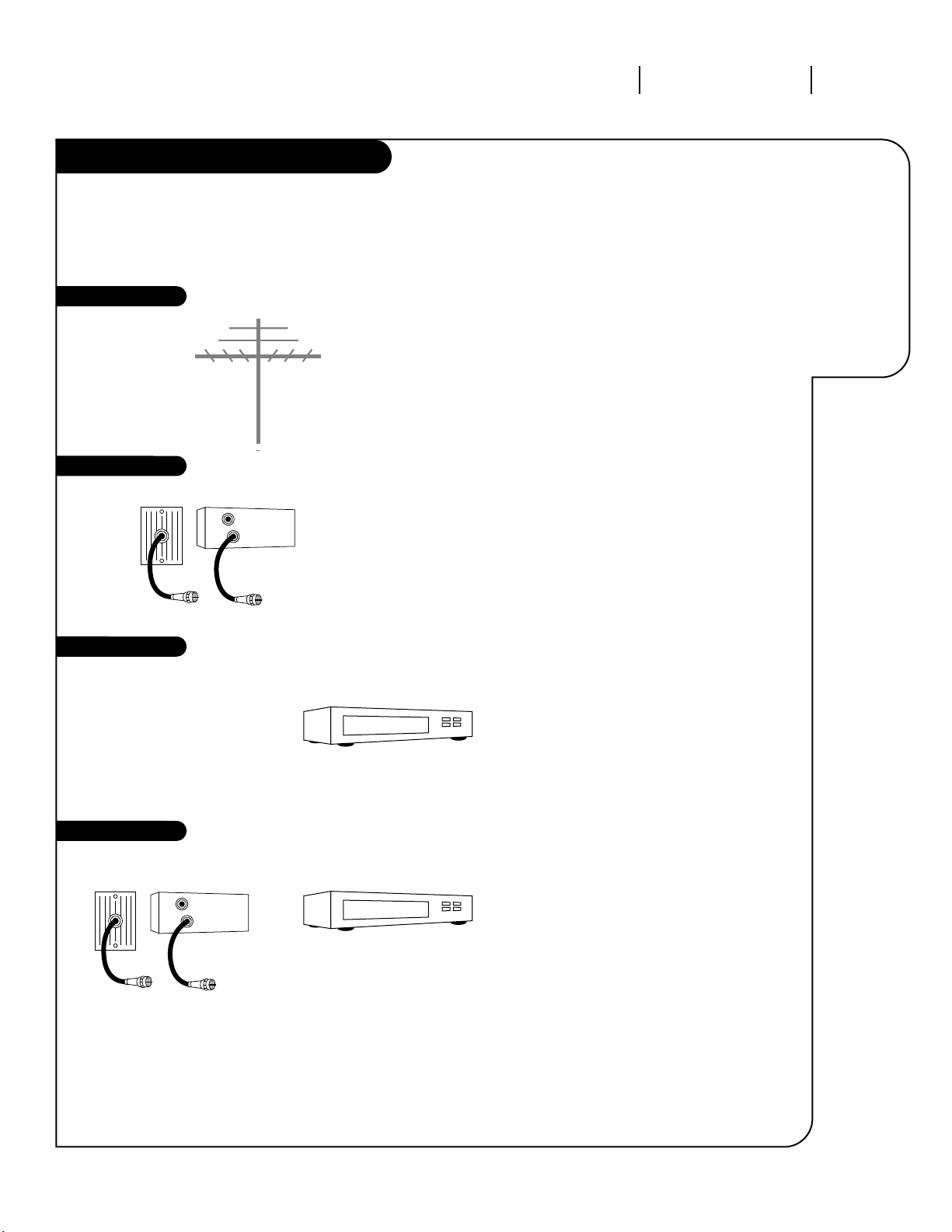
Hook-Up Directory
IMPORTANT!!
Use this page to decide where you need to begin your setup. First, find the line
below that best describes what you want to do, then go to that page number.
Cable TV
wall jack
Cable box
In
Out
Cable TV
wall jack
Cable box
In
Out
If you are using an antenna, go to . . . . . . . . . . . . . . . . . . . . . . . . . . . . . . . . . . . page 6
If you have cable or are using a cable box, go to . . . . . . . . . . . . . . . . . . . . . . . . . page 6
If you are using an antenna and have a VCR, go to . . . . . . . . . . . . . . . . . . . . . . . page 7
If you have cable or are using a cable box and a VCR, go to . . . . . . . . . . . . . . . . . . page 7
Antenna only
Cable only
Antenna with VCR
Cable and VCR
Antenna
Page 4
UNDERSTANDING YOUR TV THE JACKPACK PAGE 4
Your jack-pack
and its
various uses.
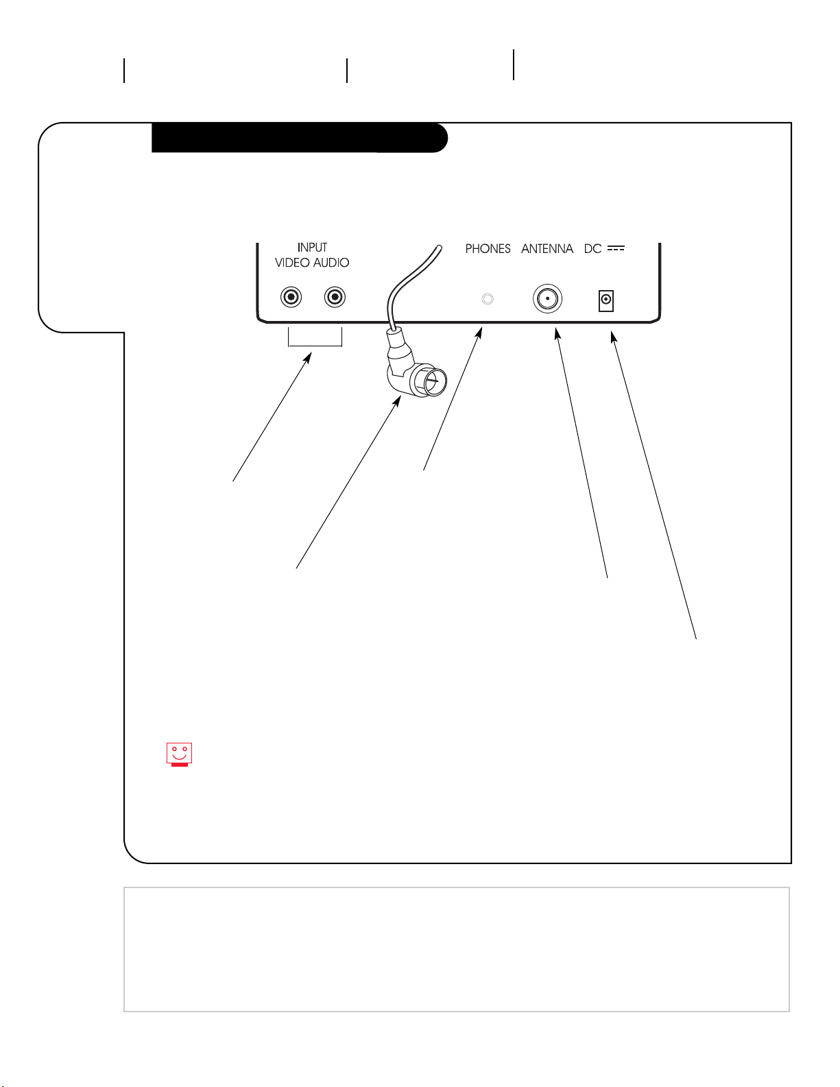
Understanding the Rear Jackpack
DC Input Jack
This is the jack to use
when you want to connect
your DC cord for direct
current (DC) power from a
12-volt source such as a
car cigarette lighter, etc.
Antenna /RF Jack
Attach your antenna,
cable-TV line or VCR
to this jack.
Phone Jacks Can
be used for connecting headphones, earphones or an external speaker. 8-ohm impedance at 1.5 watts (min) subminnature plug
3.5mm (1/8”).
TV Built-in Monopole
Antenna Connector
If you are using the
“over-the-air” built-in
antenna supplied with
the TV, connect this
to the Antenna jack.
Audio/Video Input
Jacks for connecting the
audio and video signals
from VCRs, camcorders and
various other types of
equipment.
For DC operation, use only a 12-volt negative ground power
source or the TV may be damaged.
Mini glossary
JACK A connection on the back of a TV, VCR or any other A/V device. This includes the RF jacks and the Audio/Video jacks
that are color-coded.
SIGNAL Picture and sound traveling through cable or in the air to your television screen.
206-3366-o
Page 5
UNDERSTANDING YOUR TV TV CONTROL PANEL PAGE 5
See at a
glance what
each button
on the front
of your TV
controls and
operates.
Mini glossary
SOURCE This is the term for the equipment that provides audio and video information to your Entertainment
Machine. Antenna, Cable Boxes or VCRs are examples of a source.
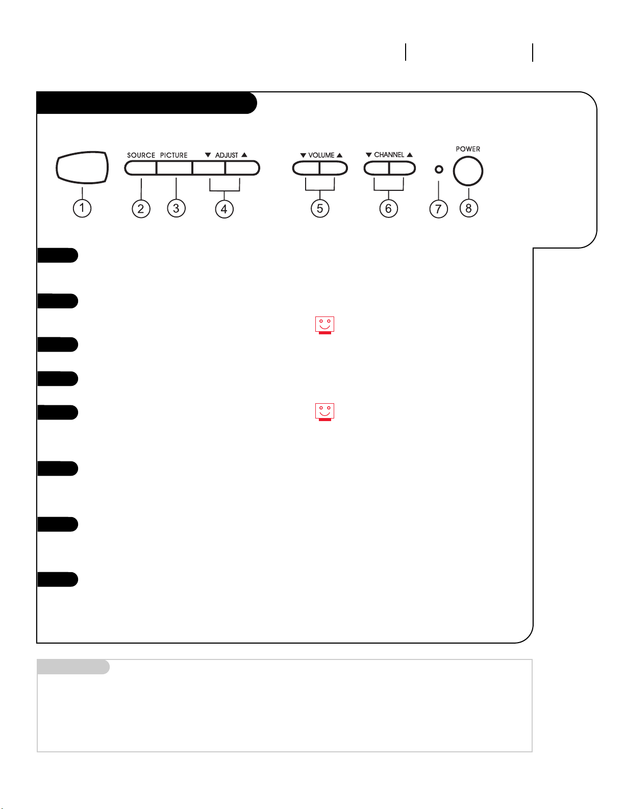
Front Panel Diagram
206-3366-o
1
This is the Remote Control Window.
Point the Remote Control at this
window to operate the TV.
This is the SOURCE button. Press it
to select your picture source, either
from Antenna or from Video.
Press repeatedly to choose the different picture adjustment options.
Press the Up/Down ADJUST buttons
to change the selected menu option.
Use either of the VOLUME Up/Down
buttons to increase or decrease the
audio level of your Entertainment
Machine.
Press the CHANNEL Up/Down buttons
to select a higher or lower numbered
channel than you are currently
watching.
This is the Power Indicator Light
that lets you know that your
Entertainment Machine is receiving
power.
This is the POWER button. Press to
turn the the TV on and off.
2
3
4
5
6
7
8
When the Power Indicator Light is
dimly lit, it indicates that the power
is connected to the TV. When the
Power Indicator Light is brightly lit it
indicates that the TV is turned on.
Always try to keep the immediate area
in front of the Remote Control Window
clear for easier remote control access.
Page 6
206-3366-o
INSTALLATION STANDARDPAGE 6
Connect an
antenna/cable
or cable box
to your
Entertainment
Machine.
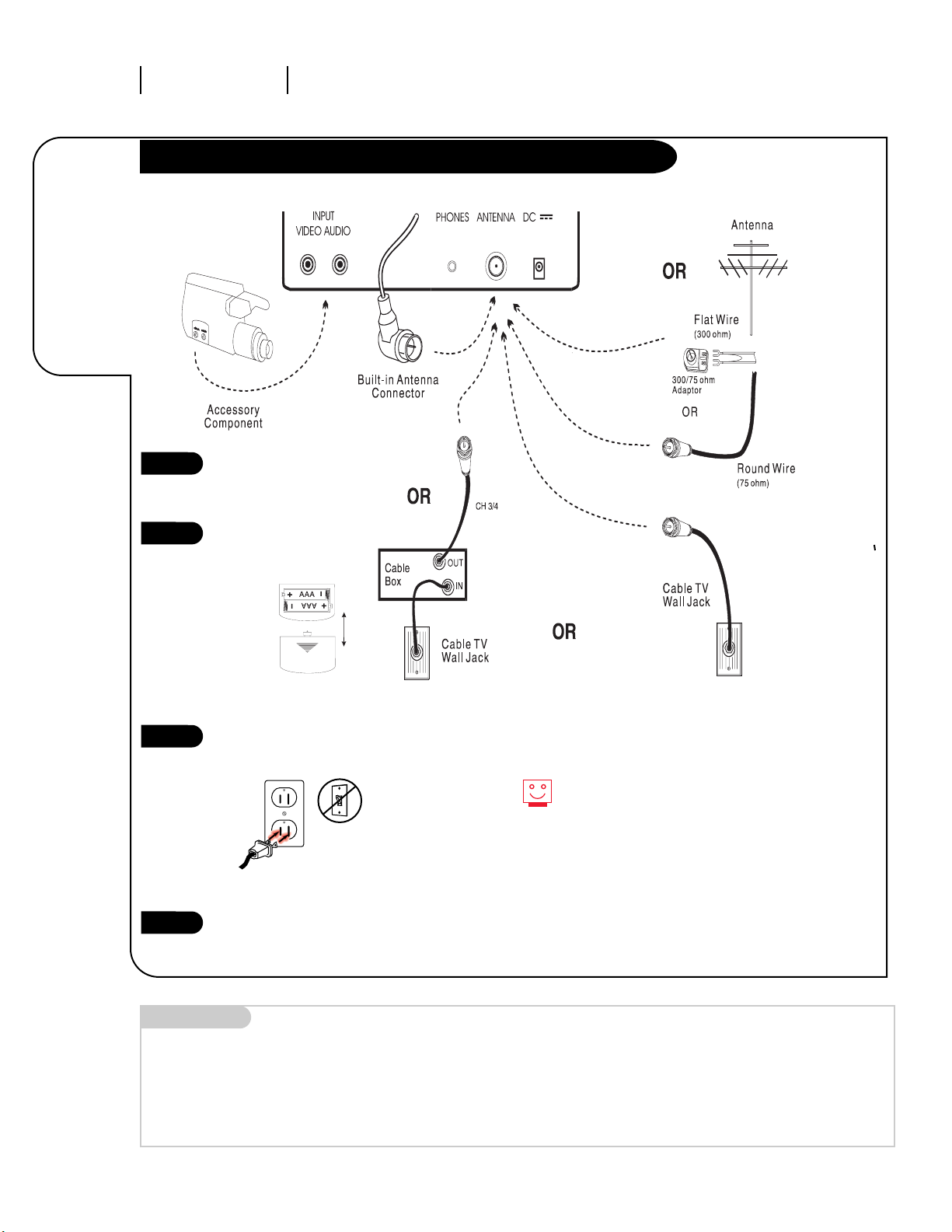
Basic Hook Up of your Antenna, Cable or Cable Box to the TV
Mini glossary
75 OHM RF CABLE The wire that comes from an off-air antenna or cable service provider. Each end looks like a hex shaped nut with a wire
sticking through the middle, and it screws onto the threaded jack on the back of your TV.
300 TO 75 OHM ADAPTER A small device that connects a two-wire 300 ohm antenna to a 75 ohm RF jack. They are usually about an
inch long with two screws on one end and a round opening with a wire sticking out on the other end.
Remember, when connecting RF
cables onto jacks, clockwise
tightens and counterclockwise
loosens.
Please refer to diagram then
hook up your
Entertainment Machine.
Remove the back of the
remote and put in two AAA
batteries.
Plug in your TV. Do not plug it
into a switched outlet.
Go to page 10 to Auto Search
your Entertainment Machine.
1
2
3
4
Page 7

206-3366-o
INSTALLATION TO VCR PAGE 7
Connect
a VCR to your
Entertainment
Machine.
Mini glossary
CABLE SERVICE The wire that supplies all your cable TV (CATV) stations.
If you’re using a cable box, leave your
TV on channel 3 or 4 and use your
cable box to change channels.
Remember, when connecting RF cables
onto jacks, clockwise tightens, and
counterclockwise loosens.
If you’re using a cable box, AutoSearch might only find the channel
your cable service is on (usually channel 3 or 4). Don’t worry, that’s all you
need!
1
2
3
4
Basic Hook Up of your Antenna, Cable or Cable Box to the TV and VCR
Hook up your
Entertainment Machine as
outlined above.
Remove the back of the
remote and put in two AAA
batteries.
Plug in your TV. Do not plug
it into a switched outlet.
Go to page 10 to Auto Search
your Entertainment Machine.
Page 8

206-3366-o
INSTALLATION QUICK STARTPAGE 8
Use Auto
Search to
automatically
find and
store all of
the stations
available in
your area.
Auto Search
With the remote control in hand,
press the POWER button to turn
on your Entertainment Machine.
Press the TV/CATV button on the
remote control repeatedly to
choose the TV picture signal
source.
Now press the AUTO SEARCH key
and the TV will collect all of the
live channels that are available
through your signal source.
1
2
3
3
2
1
Mini glossary
AUTO SEARCH Auto Search is how your Entertainment Machine finds all the channels available in your area and stores them into memory.
Select TV, if your signal is coming
from an antenna. Select STD if
your signal is coming from a cable
service.
If the picture from your cable service is weak or snowy, try running
the AUTO SEARCH in the IRC and
HRC mode until you find the mode
that gives you the best picture.
Page 9

206-3366-o
OPERATION BUTTON FUNCTIONS PAGE 9
A quick list
of all the
buttons on
your remote
and what
they do.
POWER
Turns controlled
device on and off.
Mute
Turns sound off and on.
Volume(Up/Down)
Adjusts the sound level
on your Entertainment
Machine.
Channel(Up/Down)
Cycles through available
channels.
NUMBER KEYPAD
Use for direct
channel
entry.
TV/CATV
Use to select Tuning Band,
either TV or cable service
modes STD, IRC and HRC.
SKIP/SEARCH
Allows you to skip to next
channel in memory or search
each available channel..
remote control part number
SC3492
The Buttons on Your Remote
SOURCE
Selects either the Antenna
jacks or the Audio/Video
jacks as the source of the
TV picture.
100+
Use when selecting
channel numbers
higher than 100.
Ex
ample: For 125,
press 100+, then 2
and then 5.
AUTO SEARCH
Use to find and retain all avail-
able channels in memory.
ERASE/WRITE
Use to erase or add channels
into memory.
PICTURE
Press repeatedly to select
picture settings.
ADJUST UP/DOWN
Use to change settings in
picture menu.
A broken or lost Remote Control? Call 1-800-255-6790 to purchase a replacement.
Page 10

206-3366-o
OPERATION MENUSPAGE 10
Quicker
access to
your
favorite
channel
listings
Skip/Search
Press the SKIP/SEARCH button on
your Remote Control.
If you want to see every channel
numerically in the channel scan, put
the Skip Mode into the OFF position.
If you want the channel scan to go
directly to the saved channels only,
press the SKIP/SEARCH button until
in the Skip Mode displays ON. The TV
will do the rest!
1
2
3
1
Page 11

206-3366-o
OPERATION MENUS PAGE 11
Customize
your channel
selection.
Mini glossary
ADD This function lets you save or add new channels to the list that you'll scroll through when using your remote.
ERASE This function lets you remove channels that you don't watch from the channel scan.
Setting Ch. Erase/Write
Press the ERASE/WRITE button on
the remote control.
Select the lowest channel you
wish to include in the channel
scan and select either ERASE or
ADD by pressing the ERASE/WRITE
button.
Using either the NUMBER key pad
or the CHANNEL UP/DOWN arrows
on the remote, select the next
highest channel and repeat No. 2.
Do this until you have collected
all of the channels you wish to
save in your channel scan.
1
2
3
3
1
If you erase a channel, it isn’t
gone for good. Just select it using
the NUMBER key pad on the
remote, or add it later.
Page 12

Press the PICTURE button and the
Video menu will appear. Your options
are:
• Contrast: Adjusts the level of differ
ence between white and black in
the TV picture. The more contrast,
the brighter the picture appears.
• Brightness: Increases or decreases
amount of white in the TV picture.
• Color: Adjusts levels of all colors in
the TV picture.
• Tint: Balances between amounts of
red and green in the TV picture.
Use the UP/DOWN arrows that are
positioned to the left of the PICTURE
button on the remote control to
change the picture settings
206-3366-o
OPERATION VIDEO SETTINGS
PAGE 12
Customize the
way your
picture
looks using
the Video
menu settings.
1
2
1
2
Someone left the picture looking terrible?
See how easy it is to make the picture look
great again!
Picture Settings
Page 13

OPERATION SOURCE
206-3366-o
PAGE 13
Selecting your Picture Source
Have your TV showing the live picture
from your antenna or cable service as
shown in Figure A.
Press the SOURCE button on the
remote control or on the SOURCE button on the front control panel of your
Entertainment Machine once. The TV
screen should now be blank except
for the word VIDEO which should be
displayed in the right top corner. Your
Entertainment Machine is now ready
to receive and show a video, laser
disc, etc.
Press the SOURCE button once whenever you wish to return to the live
picture from the antenna/cable..
1
2
CH 9
Changing the
SOURCE on
your
Entertainment
Machine.
If you have connected a VCR, a laser disc player or some other component to your Entertainment
Machine and are ready to play back and view a videotape, laser disc, etc., this is what you do.
FIGURE A
VIDEO
FIGURE B
3
Page 14

PAGE 14
This is how to
install the
swivel bracket
that comes
with this
Entertainment
Machine..
Header
206-3366-o
REFERENCE UNDER-CABINET MOUNT SWIVEL BRACKET
Installing the Swivel Bracket (Optional)
Mini glossary of parts
SWIVEL BRACKET ASSEMBLY 1 Swivel Bracket w/Lip Tabs. 5 Phillips Head Screws.
1 Swivel Plate 2 Pan Head Screws 5 Plastic Headed Washers.
5 Spacers (if needed).
5 Threaded Nuts
Insert the swivel bracket lip into the
top recess of the back panel of your
TV until the lip tabs at the front of
the swivel bracket snap and lock into
position.
Place the TV with the swivel bracket
attached in the right location and
position.
Be sure to leave 1 3/4” of clearance
to the wall or other surface so that
the TV can be removed when
required.
Using a graphite pencil, mark a thin
line along the back of the bracket
where it meets the cabinet’s mounting surface.
Use this pencil line as a guide for
positioning the swivel bracket template to drill the 5 holes that will be
used to secure the swivel bracket into
position. Use a drill bit at least 3/16”
in diameter to drill the 5 holes.
Install the 5 Phillips headscrews in
your cabinet. Place the swivel bracket
in position. Now thread the plastic
finish washers and the threaded nuts
on each of the 5 screws and tighten
into place.
Install the swivel plate to the back of
the TV using the 2 Pan Head screws
provided.
1
2
3
4
5
6
7
Once the swivel bracket is mounted, attach
the TV set to the bracket by sliding the TV
cabinet over the swivel bracket lip as before
until the TV snaps into its secured position.
If your cabinet has a long bottom skirt, you
may need to use the extra spacers provided
so that the bracket and TV will be located
far enough below the cabinet for viewing.
Page 15

REMOVING TV FROM SWIVEL BRACKET REFERENCE PAGE 15
Follow
these steps
to remove
the TV from
the swivel
bracket.
Under Cabinet Installation
206-3366-o
Disconnect any antenna, cables and
power cord from the TV. Shift TV so
that it is centered on the swivel
bracket.
Position one hand on the bottom
rear of the TV. Place your other
hand on the bottom front of the TV.
Swing the TV forward and up as
shown in Figure A, until you hear it
snap free of the swivel bracket lip
tabs.
Pull the TV forward, as shown in
Figure B, and away from the swivel
bracket.
1
2
3
4
FIGURE A
FIGURE B
If you use the built-in antenna as your
signal source, make sure that it is fully
retracted before you begin removing the
TV set.
Page 16

CONNECTIONS TO AC POWER PAGE 16
There are two
power cords
included with
your
Entertainment
Machine. Here
is how to
connect up
your AC power
cord.
Connecting to AC Power
206-3366-o
Locate the 2-Pin receptacle for the
AC power cord on the back panel of
your Entertainment Machine.
Insert the AC power cord into this
receptacle.(Figure A).
Place the other end ot the AC cord
into a regular 120 household outlet
(Figure B).
1
2
3
FIGURE A
FIGURE B
Make sure you use an unswitched regular
household outlet when using your
Entertainment Machine at home.
Use either a retainer or a rubber band to
hold excess cord neatly together.
Page 17

TO DC POWER CONNECTIONS PAGE 17
This is how to
connect the
DC power cord
to your
Entertainment
Machine.
Mini glossary
AC Alternating current
DC Direct current
206-3366-o
Disconnect the AC power cord from
the TV and place in a safe place.
Locate the DC power receptacle on
the back panel of your Entertainment
Machine.
Now connect the receptacle end of
the DC cord to the TV.
Plug the other end of the 12-Volt DC
power cord - yes! the end that looks
like a car cigarette lighter - into any
12-Volt NEGATIVE ground system only.
1
2
3
4
Connecting to DC Power
Make sure you disconnect the AC power
cord from your TV as the DC power will
not work while the AC plug is still connected to your Entertainment Machine.
Regardless of which power cord is used,
always connect it to the back of the TV
first.
Page 18

SYMPTOMS
Snowy picture and lousy sound.
Multiple images or ‘ghost shadows.’
Interference: Sharp lines across
the screen and lousy sound.
Normal picture but no sound.
No picture and lousy sound.
No picture and no sound —
The thing is just DEAD!
No color, but the sound is O.K.
Remote control doesn’t work.
If all else fails, call 1.847.391.8752, extension 5, between 8:30 am and 4:30 pm Central Standard Time.
206-3366-o
REFERENCE TROUBLESHOOTINGPAGE 18
Troubleshooting
Some quick
and easy
tips to fixing
problems
yourself
• Check volume control.
• Make sure the TV is not Muted.
• Try another channel. The problem may be the broadcast, not your
Entertainment Machine.
• Are the Audio A/V cables properly installed?
• Are the wires for external speakers (if you have external speakers)
Properly installed?
• Are you in TV or cable tuning mode (See Auto Program on page 8), and
should be in the other?
• Make sure output channels on all A/V equipment are on the same channel (3 or 4).
• Check that all connections are tight.
• Is the AC power plugged in?
• Check that your AC power outlet works. (Test it by plugging in something
else or try another plug.)
• Make sure your brightness and audio controls are set properly.
• Try another channel. The problem may be with the broadcast.
• Check the color control in the Video menu.
• Try another channel. The problem may be with the broadcast.
• Make sure the batteries are fresh and installed properly.
SOLUTIONS
• Check your antenna connection or location.
• Check your antenna direction and/or location.
• Make sure the wire from your antenna to your Entertainment Machine is
properly connected.
The following may cause image problems or distortion:
Electrical appliances, powerful lights, cars, trucks; Computers or
portable phones; Medical equipment
• If possible increase the distance between your Entertainment Machine and
the offending appliance. Or shut one of them off.
Page 19

206-3366-o
REFERENCE GLOSSARY PAGE 19
A complete
list of
definitions
for words
found in
this guide.
Glossary
ANTENNA The physical receiver of television signals sent over the air. A large
metal piece of equipment does not always have to be visible for your
home to be using an antenna.
75 OHM RF CABLE The wire that comes from an off-air antenna or cable service provider.
The end looks like a hex-shaped nut with a wire sticking through the
middle. It screws onto the threaded jack on the back of your TV.
300 TO 75 OHM A small device that connects a two-wire
300 ohm antenna to a
ADAPTER 75 ohm RF jack. They are usually about an inch long with two screws on
one end and a round opening with a wire sticking out on the other end.
A/V CABLES Audio/Video cables. Two (mono) or three (stereo) cables bunched
together—right audio (red), left audio (white) and video (yellow).
A/V cables are used for mono/stereo playback of videocassettes and
for higher quality picture and sound from other A/V devices.
A/V DEVICE Any device that produces video or sound (VCR, DVD, cable box,
or television).
ADD This function lets you add new channels to list that you'll scroll through
when using your remote.
ERASE This function lets you remove channels that you don't watch from the
channel scan.
AUTO SEARCH Auto Search has your Entertainment Machine automatically find all the
channels available in your area.
INPUT Refers to the jack that receives a signal from a TV, VCR or other
A/V device.
OUTPUT Refers to the jack that sends a signal out of a VCR, DVD, or other
A/V device.
SIGNAL Picture and sound traveling through cable, or on the air, to your
television screen.
SOURCE The term for the equipment that provides audio and video information
to your Entertainment Machine. Antenna, VCR, DVD players, or
Cable Boxes are examples of sources.
MONO SOUND Mono (monaural) sound is one channel of sound. On more than one
speaker, all the speakers play the same audio.
DC CONNECTION JACK Direct current power from a 12-volt source such as a car cigarette
lighter.
PHONES JACK Input jack that you can connect an earphone or headphones to for
private audio listening.
TUNER Device that picks up the signal and turns them into picture and sound.
Page 20

206-3366-o
REFERENCE MAINTENANCE
PAGE 20
Under-Cabinet Mount Swivel Bracket (Optional)
Early malfunctions can be prevented. Careful and regular cleaning can extend the amount of time you will have with
your new Entertainment Machine. Be sure to turn the power off and pull out the plug before you begin any cleaning.
Caring
for your
Entertainment
Machine.
1. Here’s a great way to keep the dust off your screen for a while. Wet a soft cloth in a mixture of
lukewarm water and a little fabric softener or dish washing detergent. Wring the cloth until it’s almost
dry, and then use it to wipe the screen.
2. Make sure the excess water is off the screen, and then let it air-dry before you turn on your
Entertainment Machine.
1. Use a soft cloth with a mild soap solution to wipe the cabinet (avoid using any cleaner that says
”industrial strength“ or ”will wash the white off of rice“ on the label).
2. Rinse the cloth and wipe the cabinet again.
3. Let the cabinet air-dry before turning the Entertainment Machine on.
If you leave your Entertainment Machine dormant for a long time (such as a vacation), it’s a good idea
to unplug the power to protect against possible damage from lightning or power surges. If you use an
off-air antenna, you may also want to disconnect it from the back of your TV before leaving.
Maintenance
Screen Cleaning
Cabinet Cleaning
Extended Absence
Page 21

206-3366-o
REFERENCE INDEX PAGE 21
Find what you
want quickly.
Index
FEATURE. . . . . . . . . . . . . . . . . . . . . . . PAGE
Antenna . . . . . . . . . . . . . . . . . . . . . . . . . . . . . . . . . . . . . . 6, 7
Auto Search . . . . . . . . . . . . . . . . . . . . . . . . . . . . . . . . . . . . . . 8
Batteries . . . . . . . . . . . . . . . . . . . . . . . . . . . . . . . . . . . . . . 6, 7
Cable . . . . . . . . . . . . . . . . . . . . . . . . . . . . . . . . . . . . . . . . 6, 7
Erase/Write. . . . . . . . . . . . . . . . . . . . . . . . . . . . . . . . . . . . . . 11
Front Panel Diagram . . . . . . . . . . . . . . . . . . . . . . . . . . . . . . . . . 5
Glossary . . . . . . . . . . . . . . . . . . . . . . . . . . . . . . . . . . . . . . . . 19
Hook-Up Directory . . . . . . . . . . . . . . . . . . . . . . . . . . . . . . . . . . 3
Jackpack . . . . . . . . . . . . . . . . . . . . . . . . . . . . . . . . . . . . . . . . 4
Maintenance . . . . . . . . . . . . . . . . . . . . . . . . . . . . . . . . . . . . . 20
Picture Settings . . . . . . . . . . . . . . . . . . . . . . . . . . . . . . . . . . . 12
Power Cords. . . . . . . . . . . . . . . . . . . . . . . . . . . . . . . . . . . 16, 17
Remote Control Diagram . . . . . . . . . . . . . . . . . . . . . . . . . . . . . . 9
Safety Information. . . . . . . . . . . . . . . . . . . . . . . . . . . . . . . . . . 2
Skip Search. . . . . . . . . . . . . . . . . . . . . . . . . . . . . . . . . . . . . . 10
Source . . . . . . . . . . . . . . . . . . . . . . . . . . . . . . . . . . . . . . . . . 13
Swivel Bracket . . . . . . . . . . . . . . . . . . . . . . . . . . . . . . . . . 14, 15
Troubleshooting . . . . . . . . . . . . . . . . . . . . . . . . . . . . . . . . . . . 18
Video Menu. . . . . . . . . . . . . . . . . . . . . . . . . . . . . . . . . . . . . . 18
Warranty. . . . . . . . . . . . . . . . . . . . . . . . . . . . . . . . . . . . . . . . 22
Page 22

Your Zenith Warranty
Direct-View Color TV Welcome to the Zenith family! We believe that you will be pleased with your new Zenith Entertainment Machine. Please read this
warranty carefully, it is a “LIMITED WARRANTY” as defined under Federal Law. This warranty gives you specific legal rights,
and you may also have other rights that vary from state to state within the U.S.A.
ZENITH RESPONSIBILITY
Service Labor During a period of 90 days from effective warranty date, Zenith will provide service labor by a Zenith authorized service center
when needed as determined by Zenith, as a result of manufacturing defects.
Parts New or remanufactured replacements for factory-defective parts will be supplied by a Zenith authorized service center for one year
from effective warranty date (color picture tube — two years). Such replacement parts are warranted for the remaining portion of the
original warranty period.
Home Service Warranty service for 21” diagonal (U.S.A.) or larger screen size models is provided in the home in most cases. (Some
repairs may require the unit to be taken by the servicer to the repair facility and returned, at no additional charge.)
Not Covered This warranty covers manufacturing defects and does not cover installation, adjustment of customer controls in the home,
installation or repair of home antenna systems, cable converters or cable company-supplied equipment; it also does
not cover damage due to misuse, abuse, negligence, acts of God or other causes beyond the control of Zenith. Any
alteration of the product after manufacture voids this warranty in its entirety.
OWNER’S RESPONSIBILITY
Effective Warranty Date Warranty begins on the date of original consumer installation. For your convenience, keep the dealer’s dated bill of sale or
delivery ticket as evidence of the purchase date.
Operating Guide Read your Operating Guide carefully so that you will understand the operation of your set and how to adjust the customer controls.
Carry-In Service Models under 21” diagonal (U.S.A.) screen size must be taken to a Zenith authorized service center for warranty service
and must be picked up by the owner.
Antenna Reception problems caused by inadequate home antenna or faulty antenna connections are the owner’s responsibility.
Important Product Registration—Please fill out and mail your Product Registration Card. It is imperative that Zenith know how to reach
you promptly if we should discover a safety problem that could affect you.
Warranty Service For warranty service information, contact any Zenith authorized service center. Parts and service labor that are Zenith’s
responsibility (see above) will be provided without charge. Other service is at the owner’s expense. If you have any problem
in obtaining satisfactory warranty service, call or write the Zenith Response Center. You must provide the model number,
serial number and date of purchase or date of original installation. Before you ask for warranty service, read “Maintenance
And Troubleshooting” in your operating guide. You might avoid a service call.
THIS WARRANTY IS IN LIEU OF ANY OTHER WARRANTY, EXPRESS OR IMPLIED, INCLUDING WITHOUT LIMITATION, ANY WARRANTY OF MERCHANTIBILITY OR
FITNESS FOR A PARTICULAR PURPOSE, AND ZENITH SHALL NOT BE LIABLE FOR ANY CONSEQUENTIAL, INDIRECT, OR INCIDENTAL DAMAGES OF ANY KIND,
INCLUDING LOST REVENUES OR PROFITS IN CONNECTION WITH THE PRODUCT.
Additional Zenith Picture Tube Protection Plan Available
Zenith offers you the opportunity to obtain additional long-term protection against failure of the picture tube in your new television.
Our Picture Tube Protection Plan enables you to avoid any unexpected picture tube repair expenses and keep your television in top condition.
It guarantees you a genuine Zenith replacement picture tube and service from a Zenith authorized service center.
Be sure to send in the Product Registration Card. We will send you and application for the Protection Plan near the expiration of the
two-year manufacturer’s warranty on the picture tube. For additional information call (847) 391-8757.
ZENITH ELECTRONICS CORPORATION
Zenith Response Center
1000 Milwaukee Avenue
Glenview, IL 60025-2493
Telephone (847)391-8752
Mon-Fri, 7:00 a.m.-8:00 p.m. CST
www.zenith.com
IN CANADA,WRITE OR CALL US AT:
LG Electronics
235 Superior Blvd.
Mississauga, Ontario, Canada LST-2L6
tel: (905)795-6240,
fax:(905) 670-2379
IN MEXICO,WRITE OR CALL US
LG Electronics
Av. San Andres Atoto,No 8
Col. San Andres Atoto, Naucalpan
Estado de Mexico,
C.P. 53500
tel: 01 (800) 50 481
y en el D.F. 359 43 55
fax 01 (800) 50 733
y en el D.F. 357 17 56
206-3366-o
ZENITH CONSUMER SERVICE
Factory Owned Service Center
Home & Carry-in Service
Television/VCR
Parts and Accessories
PTV/Computer
801 E. Roosevelt Rd
Lombard, IL 60148
(630) 705-2830
Service Hours:
M-F 8-6, Sat 9-2
Will accept UPS shipments
201 James Record Rd.
Building 4
Huntsville, AL 35824
(205) 461-8583
Page 23

206-3366-o
 Loading...