

Page 1

VC6000 Series
Quick Reference Guide
Draft - October 16, 2008
Page 2

© 2008 MOTOROLA, INC. All rights reserved.
Motorola reserves the right to make changes to any product to improve
reliability, function, or design.
Motorola does not assume any product liability arising out of, or in
connection with, the application or use of any product, circuit, or
application described herein.
No license is granted, either expressly or by implication, estoppel, or
otherwise under any patent right or patent, covering or relating to any
combination, system, apparatus, machine, material, method, or process
in which Motorola produc ts might be used. An implied licens e exis ts on ly
for equipment, circuits, and subsystems contained in Motorola products.
MOTOROLA, and th e Stylized M Log o are regi stered in the US Patent &
Trademark Office. Other product names mentioned in this manual may
be trademarks or registered trademarks of their respective companies
and are hereby acknowledged.
Motorola, Inc.
One Motorola Plaza
Holtsville, N.Y. 11742-1300, USA
www.motorola.com/enterprisemobility
Warranty
Subject to the terms of Motorola’s hardware warranty statement, the
VC6000 series products are warranted against defects in workmanship
and materials for a pe rio d of one year from the da te o f sh ipm en t. F or th e
complete Motorola hardware product warranty statement, go to:
www.motorola.com/enterprisemobility/warranty.
Patents
This product is covered by one or more patents. For patent information
go to: www.motorola.com/enterprisemobility/patents.
Page 3

Quick Reference Guide 1
Introduction
The Motorola VC6000 series is a rugged vehicle or fixed-mount
computer . It is specifi cally desig ned for the harsh c onditions of th e mobile
environment areas.
The VC6000 also serves as a stationary indoor host computer for
communication and control of outdoor VC6000 seriess.
The computer enables real-time data access, collection, capture and
report of information related to the driver’s workflow, status and location.
The fixed-mount computer consists of a touch-screen with an integrated
QWERTY keyboard. Data can be entered using the touch-screen or
keyboard.
The computer has multiple communication capabilities that include:
Wireless Local Area Network (WLAN), Wireless Wide Area Network
(WWAN), Bluetooth
Bluetooth technology is used for cordless connection of peripheral
devices such as printers, bar code scanners, handsfree speakers and
headsets to the comp uter. Cellula r and WiFi radios a re used to excha nge
voice and data with wide and local area networks. Among its many
communication interfaces, the computer contains an internal GPS
module, ensuring reliable and accurate vehicle location.
The VC6000 Vehicle Computer series is designed only for industry and
commercial use. In in door applicati ons, the VC600 0 can serve as a f ixedmount office computer for communication and data collection.
The VC6000 is not
The computer, antenna(s) and other accessories of the VC6000 require
a professional installation performed by trained and licensed personnel.
For proper installation requirements, contact your professional installer,
VAR, or antenna manufacturer.
TM
and a Global Positioning System (GPS) receiver.
designed to operate as portable lap-top computer.
Page 4
2 VC6000 Series Vehicle Computers
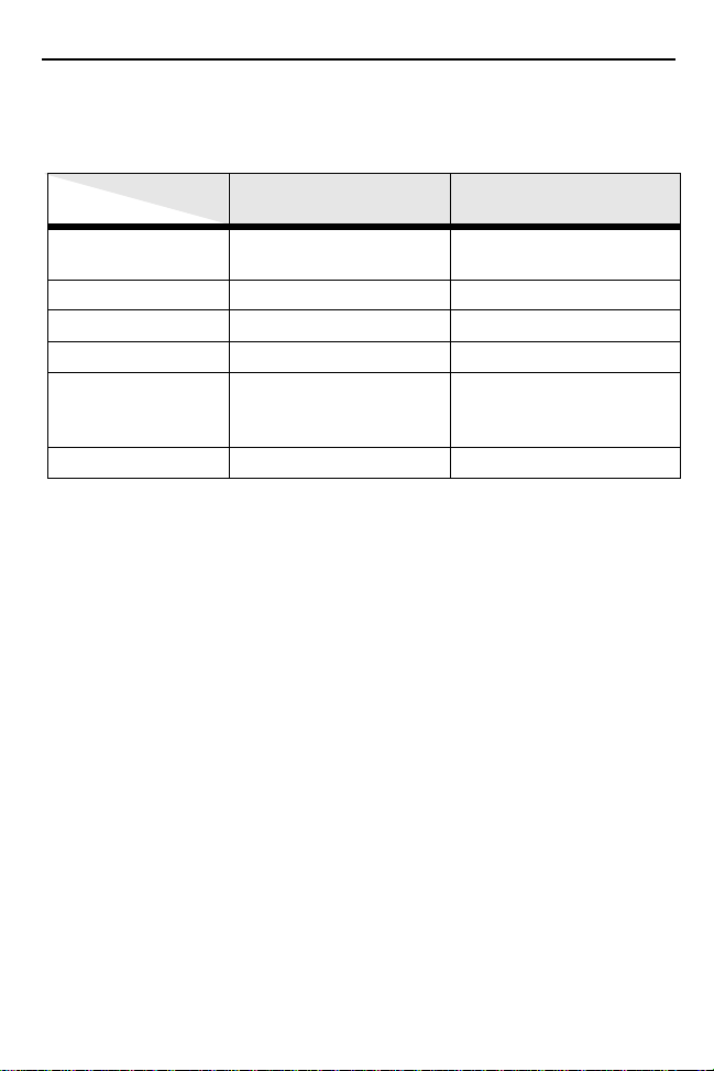
Model Configurations
This guide covers the configuration of the following VC6000 series models:
Model
Configuration
Operating System Windows Mobile 6.1
GPS No Y es
Bluetooth
Wireless LAN No Yes (802.11 a/b/g)
Cellular radio
(HSDPA, UMTS,
GSM, GPRS, EDGE)
Vehicle Telem etry No Yes
Classic
Yes Yes
No Yes (Voice and data)
VC6000 VC6096
Windows Mobile 6.1
Professional
The vehicle computer features:
• Ergonomic design with a color LCD touch screen
• Windows Mobile 6.1 operating system
• Internal Bluetooth radio to enable wireless connection to a Bluetooth
printer, bar code scanner, headset and other Bluetooth peripherals.
• Connection to WLAN in 802.11a/b/g standards (VC6096 only)
• Connection to WWAN using a Global System for Mobile communication (GSM) cellular radio and High-Speed Downlink Packet Access
(HSDPA) (VC6096 only)
• 10/100 Ethernet port for connection to Local Area Network (LAN)
• Vehicle motion and location detection via the vehicle telemetry and the
GPS receiver (VC6096 only)
• Serial RS232 interface
• Full speed USB ports
• Wide-range of input power (10 V DC to 33 V DC) to accommodate a
wide range of vehicles
• Reliable operation in cold enviro nments, as low as -20 °C (- 4 °F)
• Maximum operational temperature 60 °C (140 °F)
Page 5
Quick Reference Guide 3
Features
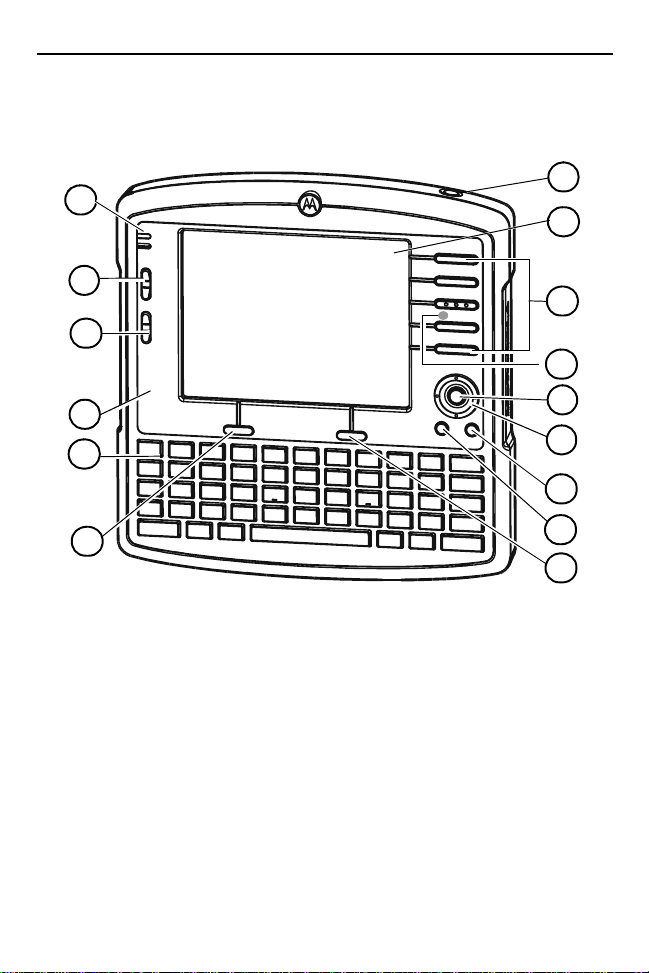
Front Features
1
2
15
3
14
4
13
5
6
7
1
1. Reset Button with system indication LED
2. Two green LEDs driven by application
3. Volume up/down key (6 levels)
4. Brightness up/down key
5. Microphone (embedded)
6. Full QWERTY keypad
7. Left soft key
8. Right soft key
1
See “System Indication LED” on page 17.
2
For LED indications, refer to your enterprise application manual.
3
For key function, refer to the text displayed on the screen.
4
For operation, refer to your enterprise application guide.
3
3
9. Home key
10. Back key
2
11. Navigation key
12. Select key
13. Speaker
14. Function keys
15. Touch screen
(embedded)
12
11
10
9
8
4
Page 6
4 VC6000 Series Vehicle Computers
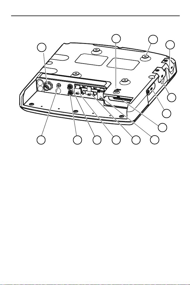
Back Features
1
1. PWR - Power connector
2. GPS antenna connector
3. WWAN antenna connector
4. WLAN antenna connector
5. Mini USB port, type B
6. USB port, type A
7. 10/100 Ethernet port
2
2
2
13
43
8. Auxiliary port
9. SIM card slot
10. SD memory card slot2
1
11. USB port, type A
12. M4 screw mounting bosses
13. M4 Ground screw boss
52
6
2, 3
2
12
11
10
9
8
7
2
1
Rotate counterclockwise to fasten connector.
2
Keep covered when not in use.
3
Includes: 8 digital inputs, 8 digital outputs, 2 analog inputs, 2 pins for de-
bugging, 2 full RS232, CAN2.0 - J1939 (Telemetry), J1708 (Telemetry).
Page 7

Quick Reference Guide 5
Unpacking
The following items are contained inside the shipping box:
• VC6000 series
• Hardware Kit (including five M4 installation screws)
•This guide
NOTE A hardware kit that contains optional accessories is
3
provided s eparately inside the shipping box.
Optional Accessories
Part Number Description
FLN4048 Combination Antenna
8508851K59 External GPS Antenna
0102246H51 Indoor Power Supply
50-16000-2212 AC Cord (USA)
3087568V83 VC6096 WWAN RF Cable (3m, 9.8ft.)
3087568V84 VC6096 WLAN RF Cable (3m, 9.8ft.)
3071815Y17
3071815Y13 VC6096 Vehicle Power Cable
3071815Y15 9-Pin Deutsch Cable
3071815Y23 9-Pin Deutsch Cable (J1939 protocol)
3071815Y24 9-Pin Deutsch Cable (J1708 protocol)
3071815Y14 6-Pin Deutsch Cable
3089906V60 50 Pin Cable
3089906V63 9-Pin Deutsch Telemetry Ca ble
3089906V61 6-Pin Deutsch Telemetry Ca ble
3071815Y25 9-Pin Deutsch Telemetry Cable (J1708 pro tocol )
3071815Y26 9-Pin Deutsch Telemetry Cable (J1939 pro tocol )
VC6096 Cigarette Lighter Cable (CLA) Power Supply
Cable
Page 8
6 VC6000 Series Vehicle Computers
Installation
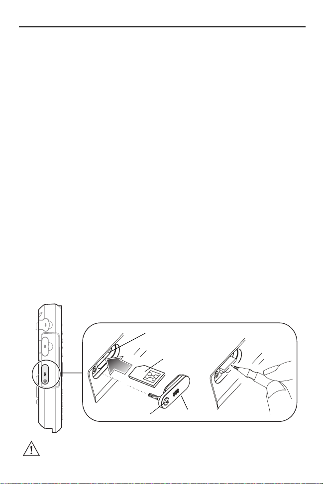
Installing a SIM Card (VC6096 only)
Before using the VC6000 seri es in a cellu lar network , make su re that th e
VC6000 series is equipp ed with a Subscribe r Identity M odule (SIM) card,
obtained form your service provider. The SIM card is a small smart card
that fits into the VC6000 series. The SIM card holds the personalized
information about the VC6096, including network activation and phone
book entries.
To install the SIM card:
1. Remove the T8 screw that secures the SIM card door and open the
door.
2. Position the SIM Card with the contacts facing the back of the
VC6000 series, and insert into the SIM Slot. The SIM Card corner
notch fits into the slot only one way (See figure below).
3. Use a pen to push the SIM Card inwards to lock.
4. Place the SIM Card Door and secure the T8 screw.
NOTE The VC6000 series powers on only if the screw is fully
3
5. Torque the screw to 3.4 kgf-cm (3 in-lbs).
secured.
SIM Slot
SIM Card
T8 Screw
CAUTION Ensure to torque the screw to seal the VC6000 series
properly. Otherwise, sealing can be compromised.
SIM Card Door
Page 9

Quick Reference Guide 7
Installing an SD Memory Card
A Secure Digital (SD) memory ca rd provide s secondary non-volat ile dat a
storage. Up to 2GB memory cards can be used. The card slot is located
on the side panel of the VC6000 series.
To install the memory card:
1. Lift up the protective rubber cap that covers the Memory Card Slot.
2. Position the SD Memory Card with the contacts facing the back of the VC6000 series and inse rt into the Mem ory Card Slot. Th e corner notch of the SD Memory Card fits into the Memory Card Slot only one way.
3. Use your pen to push the SD Memory Card inwards to lock.
4. Replace the Protective Rubber Cap to seal the Memory Card Slot.
Protective Rubber Cap
Memory
Card Slot
SD Memory Card
Page 10
8 VC6000 Series Vehicle Computers
Mounting the VC6000 series
Guidelines for Routing Cables
• Establish a ne at route for t he cable, stayi ng clear o f moving part s or hot
surfaces.
• Fix the cable to an existing cable runs inside the vehicle using cable
ties.
• When the cabling must go through a panel, use a suitable cable guard.
• When fixing a conduit or a cable on the outside of a vehicle, use
P-Clips. Either dril l and ta p the hole or use a nut and bo lt to secu re the
clip.
• Ensure the cable does not have tight bends. The minimum recommended radius is 6.35 cm (2.5 inches).
• Ensure cables do not swing or chafe on the structure. This often
requires using cable ties approximately every one foot, and ensuring
the cables do not flex often, especially where they connect to the
VC6000 series.
• If you must re-position the VC6000 serie s occa siona lly, ensu re there is
enough slack in the cable to accommodate movement without putting
tension on the cable.
• Take the power from as close to the battery terminals as possible, and
avoid using existing wiring.
• Ensure that all fuses are as close as possible to the power source.
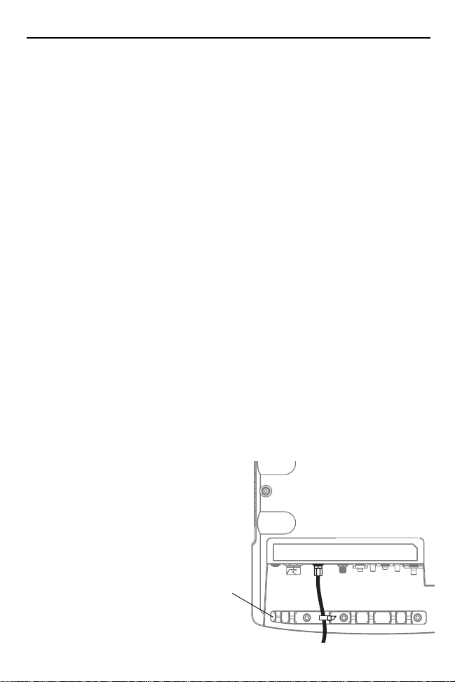
• Use plastic cable ties to
secure the cables to
the cable tie bracket of
the VC6000.
Cable Tie
Bracket
Page 11

Quick Reference Guide 9
Connecting the Vehicle Power Cable
CAUTION DO NOT install the VC6000 series in a vehicle with a
positive ground electrical system.
To connect the pow er cable:
1. Disconnect the power terminals from the vehicle battery.
2. Connect the black wire to the vehicle’s negative power source.
3. Connect the green wire to the vehicle’s ignition switch.
4. Connect the red wire to the vehicle’ s posi tive powe r source. Plac e a 10 A SLO BLO fuse inside the fuse holder, connected in-line with the Red Wire approximately 4” from the cable end, as shown below.
5. Connect and turn clockwise to lock the Power Plug to Power Connector (PWR) of the VC60 00 se ries (s ee Back Features on page 4).
The length of the cable is 9.8 ft (3 m).
Power Plug
6. When routing wires, slide Shrink Tubing over wires as required.
7. Connect the power terminals of the Vehicle Power Cable to the terminals of the vehicle battery.
10 A Fuse SLO BLO
Fuse Holder
Green Wire
Black Wire
Red Wire
Shrink Tubing
Cigarette Lighter Cable
The Cigarette Lighter Cable is a power extension cord that plugs into a
cigarette lighter ou tlet of th e vehi cle . The ma ximu m leng th of the c able i s
8.2 ft (9.1 m).
Power Plug
10A Fuse SLO BLO
Page 12

10 VC6000 Series Vehicle Computers
r
Connecting the Telemetry Cable
Telemetry Cable
1. Plug the J1 connector into the Auxiliary port of the VC6000 series (see Back Features o n page 4) and fa ste n the co nnection screws of the connector.
2. Plug connectors J2 and J3 to the telemetry receptacles of your vehicle data bus.
3. Connect the I/O Wires as required.
J1 To VC6000 series Auxiliary port
J2 (RS232) Connector
I/O Wires: 8 digita l inputs, 8 dig ital out puts, 2 analo g
inputs, Debug (2 wires fo r debugg ing). Se e labe l on
wires. Maximum current through wires 0.5 A
NOTE For Input/Output (I/O) Wires c onn ec tion s, refer to the VC6000
3
Series Product Reference Guide.
J3 Deutsch 6 o
9 pin Telemetry
Connector
Deutsch 6 and 9 Telemetry Cables
1. Plug the J1 into the Auxiliary port of the VC6000 series (see Back
Features on page 4) and fasten the connection screws of the con-
nector.
Page 13

Quick Reference Guide 11
2. Plug connectors J2 to the telemetry receptacles of the vehicle data bus.
J2 To vehicle Deutsch 9 Connector
J1 To computer Auxiliary port
J2 To vehicle Deutsch 6 Connector
Grounding
CAUTION The VC6000 series should operate only in negative
ground electrical system s. C hec k the grou nd pol ari ty of
the vehicle before starting the VC6000 series installation
to verify that the p olarity is corre ct. Ac cident ally reversing
the polarity will not damage the VC6000 series, but will
cause the cable fuse to blow.
Page 14

12 VC6000 Series Vehicle Computers
Mounting the Combination Antenna (VC6096 only)
The Combination Antenna is an optional omni-directional WWAN and
WLAN antenna used with the VC6096. The antenna mounts
inside/outside the vehicle cabin or indoors/outdoors.
The antenna has two external RF connectors that connect to the
VC6096 via two low loss RF coax cables.
CAUTION To avoid damage to the VC6000 series, make sure to
disconnect the power cable from the VC6000 series
before connecting the an tenna c able. W hen ins tal ling th e
antenna cable, ma ke s ure to c on nec t the a nte nna side of
the cable before connecting to the VC6000 series.
Installation guidelines:
1. For best performance, it is recommended to install the antenna outside of the cabin . When inst alli ng the antenn a in the v ehicl e cabin o r
indoors, keep a minimum distance of 70 cm (2.3 ft) between the
antenna and the VC6000 series.
2. The ant enna
should be directed
vertically to the
horizon to assure
maximum exposure.
3. To ensure best
performance, the
antenna should be
mounted as far
away as possible
from walls, floors
and metal containing objects. Keep
an obstacle free
zone of 10 cm (3.9
inches) from walls, cabinets, air duct, metal-framed windows, doors
etc.
4. When mounting the antenna inside the vehicle, it is recommended to install the antenna at the top right hand side of the windshield.
M4 screw mounting bosses used for mounting bracket
or
Vehicle
Windshield
WWAN
Cable
WLAN
Cable
Page 15

Quick Reference Guide 13
WARNING! 1. Keep a minimum lateral distance of 20 cm (8 inche s)
between the driver/p assenger an d the antenna. Cont act
your professional installer, VAR, or antenna
manufacturer for proper installation requirements.
2. To ensure safe driving, when mounting the
Combination Antenna next to the windshield, do not
block the driver’s field of view.
Mounting the GPS Antenna (VC6096 only)
The VC6096 is supplied with an internal module of Global Positioning
System (GPS).
Connect the cable connector of the GPS antenna to the GPS connector
at the back of the VC6096.
CAUTION To avoid damage to the VC6000 series, make sure to
disconnect the power cable from the VC6000 series
before connecting the antenna cable.
Installation guidelines:
1. Recommended GPS antenna - Motorola part number 8508851K59.
2. The GPS antenna must be mounted on the top of the dashboard or vehicle roof. For best performance, install the GPS antenna on the center-line of the vehicle roof.
3. Keep a minimum distance of 40 cm (16 inches) between the Combination antenna and the GPS antenna.
4. The antenna is attached by a magnet to a flat metal surface (minimum 2.75 inches x 2.75 inches, 7 cm x 7 cm). Before mounting the
GPS antenna on a dashboard, install a flat Metal Plate on the dashboard to hold the GPS antenna.
5. The antenna should be directed parallel to the horizon to assure exposure to as many satellites as possible.
6. If possible, the antenna location must not be obstructed by any structure or object. When mounti ng the antenna on a roof ensure at least 3” of clear space around it.
Page 16

14 VC6000 Series Vehicle Computers
GPS Antenna
Metal Plate
Connecting the VC6000 Series Indoor
When using the VC600 0 serie s indo or, the VC600 0 series c an be place d
on a desk and powered using an Indoor Power Supply Unit.
To connect the VC6000 series indoor:
1. Connect a ground wire between the VC6000 series and the facility
ground system.
WARNING: To ensure proper grounding, use a 18AWG ground
wire between the VC6000 series Ground Point (GND)
and the facility ground system.
The ground wire ring lugs should be connected to the Ground Point
(GND) at the back of the VC6000 series using M4 screw.
2. Mount the Combination Antenna outdoor. Contact the mast of the
antenna, by a metal bond ing , to a gr ou nd wire that run s directly into
the earth, via a d eep groun d rod. For a ntenna i nstall ation gui delines,
See “Mounting the Combination Antenna (VC6096 only)” on
page 12.
WARNING! Keep a minimum lateral distance of 20 cm (8 inches)
between the VC6000 series user and the antenna.
Contact your professional installer, VAR, or antenna
manufacturer for proper installation requirements.
3. Connect the WWAN plug of the Combination Antenna cable to the WWAN antenna connector at the back of the VC6000 series (VC6096 only).
Page 17

Quick Reference Guide 15
r
4. Connect the WLAN plug of the Combination Antenna cable to the WLAN antenna connector at the back of the VC6000 series (VC6096 only).
5. Attach the 12 V DC cable of the Indoor Power Supply Unit to the
Power Connector at the back of the VC6000 series and turn clockwise to lock.
6. Connect the AC Cord into the Indoor Power Supply Unit.
7. Connect the AC Cord plug into a 100-240 V AC / 50-60 Hz Power Outlet.
100-240 V AC / 50-60 Hz Power Outlet
AC Cord
Indoor Power Supply Unit
For indoor use only in dry locations
12 V DC Cable
WLAN antenna connecto
Power Connector
NOTE The total length of the power supply cables is 14.1 ft (4.3 m).
3
WWAN antenna connector
Ground Point
GND
Page 18

16 VC6000 Series Vehicle Computers
Optional Mounting
The following mount examples should be used for installing the VC6000
series inside the vehicle. For optional mounting instructions, refer to the
documentation provided by the mount manufacturer.
WARNING! Vehicles equipped with air bags - An air bag inflates
with great force. D O N OT install the VC60 00 s eri es or
place objects, including other communication
equipment, in the area over the air bag or in the air bag
deployment area. If the communication equipment is
improperly inst a ll ed and the air bag inflat es , t his c ou ld
cause serious injury.
Free-standing Pedestal Mount
R
The mount allows the VC6000
series to be easily readjusted to
either the driver or passenger
sides in the most comfortable
location. A single adjustment knob
enables adjustment of both upper
Adjustment knob
and lower ball joints
simultaneously. The mount affixes to the VC6000 series using the M4
screws, included i nside th e Ha rdware Ki t, and to th e ve hicle ’s dashbo ard
using self tapping screws or bolts, provided by the mount manufacturer.
Recommended mount: VESA plate RAM mount with 6.35 cm (2.5
inches) diameter base.
Desk Mount
The mount allows the VC6000 series to be easily
placed on a desk and adjusted to a most
comfortable screen view position. A single
adjustment knob enables adjustment of both upper
and lower ball joints simultaneously. The mount
affixes to the VC6000 series using the M4 screws,
included inside the Hardware Kit.
Page 19

Quick Reference Guide 17
Operating the VC6000 series
System Indication LED
The system indication LED is located inside the Reset Button.
The System Indication LED indicates the following states:
LED State Indication
Off Normal operation
Fast flashing amber • Critical power event. Input power is out of
operating range. The VC6000 series may turn
off - save your entries.
• Vehicle engine start - no action is required.
• Cold reset is active - no action is required.
Slowly flashing amber Critical temperature event. Ambient temperature
is out of operating range -4 °F to 140 °F (-20 °C
to 60 °C). The VC6000 series may turn off.
Controlling Screen Brightness
There are five levels of screen brightness (including turning off).
To adjust the brightness of the screen, pres s the Brig htness do wn but ton
to decrease the brightness or the Brightness up button to increase the
brightness. The VC60 00 se ries automat ically re turns to no rmal opera tion
after six seconds if the Brightness up/down key is not pressed.
Controlling Keypad Illumination
There are five levels of Keypad Illumination. To adjust the Keypad
Illumination:
1. Press the Ctrl key to lock in down position.
2. Press the Brightness up/down key to increase/d ec reas e th e ke ypad illumination. The VC6000 series automatically returns to normal operation after six seconds if the up/down key is not pressed.
3. Press the Ctrl key to unlock in up position.
Page 20

18 VC6000 Series Vehicle Computers
Standby Mode
Standby mode is a power saving mode enabled only when the vehicle
ignition key is switched to the OFF position.
In Standby mode, the screen display and backlight illumination automatically turn off after a period of two minutes when VC6000 series is not
active.
Resume from Standby Mode
To resume from Standby mode, press any
key, or touch the screen, or momentarily
press the Reset Button .
The VC6000 series can be set to
automatically resume from Standby mode
when: turning On the ignition key,
connecting or removing a USB device,
pressing a keyboard key, receiving an alarm,
pressing the touch screen, communicating
over Bluetooth, comm unica ting ov er WW AN.
Reset Button
Page 21

Quick Reference Guide 19
Resetting the VC6000 series
If the VC6000 series stops responding to inputs, perform the reset
actions in the following order:
Initial Reset
Press and hold the initial reset Button for one second and release.
Warm Boot
Warm boot ma y beco me nec essa ry wh en an ap plica tion run nin g on yo ur
VC6000 series does not respond after performing initial reset.
CAUTION Warm boot may cause lost of information from programs
currently running on the computer.
To perform warm boot:
Press and hold the Reset Button for five seconds and release.
Cold Boot
Cold boot may become necessary when your VC6000 series is jammed
and does not respond after performing warm boot.
Cold boot restarts the VC6000 series by performing an ungraceful
shutdown of a ll runni ng app lication s and p owering o ff the VC6000 series.
Cold boot resets information stored in all running applications.
Data saved on flash memory or a memory card is not lost.
To perform a cold boot:
Press and hold + + Reset Button .
Function Keys
The five function k eys on the front ri ght ha nd si de of the p anel can be se t
to perform dedicated functions, such switching between different
software application screens. To know more about the function of each
key, refer to the application operating ma nua l.
Page 22

20 VC6000 Series Vehicle Computers
Troubleshooting
Problem Cause Solution
The VC6000
series does not
power on.
Low Battery
level warning is
issued.
LCD and
Keypad
backlight do not
function.
Display
backlight
intensity is
reduced.
The VC6000
series powers
off during
operation.
Vehicle ignition key in
OFF position.
SIM door is open. Close the SIM door
Drained vehicle battery. Charge or replace battery.
Power cable is
disconnected.
Vehicle battery voltage
dropped below 9 V DC.
Critical Battery level.
Vehicle battery Voltage
dropped below 8V.
Display temperature is
below 10 °C or above 35
°C (below 50 °F or above
95 °F).
VC6000 series
temperature is out of
range:
-4 °F to 140 °F
(-20 °C to 60 °C).
Switch on the vehicle
ignition key to the ON
position.
properly and secure screw.
Connect the Power cable.
Start the vehicle engine to
charge the battery.
Replace battery.
Start the vehicle engine to
charge the battery.
Replace battery.
Control the tempera ture
inside the vehicle.
Control the tempera ture
inside the vehicle.
Page 23

Quick Reference Guide 21
Regulatory Information
All Motorola devices are designed to be compliant with rules and
regulations in locations they are sold and will be labeled as required.
This device is approved under Enterprise Mobility business of Motorola,
Inc., (“Motorola”).
Regulatory Information is available in French, Italian, German, Spanish
(Spain), Portuguese, Greek, Turkish, Czech, Danish, Estonian, Finnish,
Swedish, Hungarian, Dutch, Norwegian, Polish, Romanian, Slovak,
Slovenian, Simplifi ed C hin es e. Loc al l ang uage translations are a va ila ble
at the following web site: www.motorola.com/enterprisemobility/manuals
This device is approved under the Motorola, Inc (“Motorola”). Any
changes or modific ations to Motorol a equipment, no t expressly app roved
by Motorola, could void the user's authority to operate the equipment.
Antennas: Use only the supplied or an approved replacement antenna.
Unauthorized antennas, modifications, or attachments could cause
damage and may violate regulations.
CAUTION Only use Motorola approved and UL Listed
accessories.
Do NOT attempt to charge damp/wet mobile
computers. All components must be dry before
connecting to power source.
.
Country Approvals
Regulatory marki ngs are applied to the device si gni fying the radio(s) are
approved for use in the following countries: United States, Canada,
Australia and Europe 1, 2.
Please refer to the Motorola Declaration of Conformity (DoC) for details
of other country markings . This is available at:
www.motorola.com/enterprisemobility/doc.
NOTE 1: For 2.4GHz Products: Europe includes, Austria, Belgium,
Czech Republic, Cyprus, Denmark, Estonia, Finland, France,
Germany, Greece, Hungary, Iceland, Ireland, Italy, Latvia,
Page 24

22 VC6000 Series Vehicle Computers
Liechtenstein, Lithu ani a, Lux em bou rg, Ma lt a, Netherlands,
Norway, Poland, Portugal, Slovak Republic, Slovenia, Spain,
Sweden, Switzerland and the United Kingdom.
NOTE 2: The use of 5GHz RLAN's has varying restrictions of use;
please refer to the Motorola Declaration of Conformity (DoC)
for details.
CAUTION Operation of the device without regulatory approval is
illegal.
Health and Safety Recommendations
Ergonomic Recommendations
CAUTION In order to avoid or minimize the potential risk of
ergonomic injury follow the recom me nda tio ns bel ow.
Consult with your local Health & Safety Manager to
ensure that you are adhering to your company's safety
programs to prevent employee injury.
• Reduce or eliminate repetitive motion
• Maintain a natural position
• Reduce or eliminate excessive force
• Keep objects that are used frequently within easy reach
• Perform tasks at correct heights
• Reduce or eliminate vibration
• Reduce or eliminate direct pressure
• Provide adjustable workstations
• Provide adequate clearance
• Provide a suitable working environment
Page 25

Quick Reference Guide 23
Vehicle Installation
RF signals may affect improperly installed or inadequately shielded
electronic systems in motor vehicles (including safety systems).
Check with the ma nufacture r or its re present ative reg arding yo ur vehicl e.
You should also consult the manufacturer of any equipment that has
been added to your vehicle.
An air bag inflates with great force. DO NOT place objects, including
either installed or portable wireless equipment, in the area over the air
bag or in the air bag dep loym ent area . If in-ve hicle wirel ess equi pment i s
improperly installed and the air bag inflates, serious injury could result.
Position your device within easy reach. Be able to access your device
without removing your eyes from the road.
Note: Connection to an alert device that will cause a vehicle horn to
sound or lights to flash, on receipt of a call on public roads, is not
permitted.
Safety on the Road
Do not take notes or use the device while driving. Jotting down a “to do”
list or flipping through your address book t a kes attention away from yo ur
primary responsibility, driving safely.
When driving a car, driving is your first responsibility - Give full attention
to driving. Check the la ws and regula tions on the use o f wire less devices
in the areas where you drive. Always obey them.
When using a wireless device behind the wheel of a car, practice good
common sense and remember th e following tips:
1. Get to know your wireless device and any features such as speed dial and redial. I f availab le, these fea tures hel p you to place yo ur call without taking your attention off the road.
2. When available, use a hands free device.
3. Let the person you are spe ak ing with k now yo u are dr iv ing ; if ne ce ssary, suspend the call in heavy traffic or hazardous weather conditions. Rain, sleet, snow, ice, and even heavy traffic can be
hazardous.
Page 26

24 VC6000 Series Vehicle Computers
4. Dial sensibly and assess the traffic; if possible, place calls when you
are not moving or before pulling into traffic. Try to plan calls when
your car will be stationary. If you need to make a call while moving,
dial only a few numbers, check the road and your mirrors, then continue.
5. Do not engage in stressful or emotional conversations that may be distracting. Make people you are talking with aware you are driving and suspend conversations that have the potential to divert your attention from the road.
6. Use your wireless phone to call for help. Dial the Emergency services, (9-1-1 in the US, and 1-1-2 in Europe) or other local emergency number in the case of fire, traffic accident or medical
emergencies. Remember, it is a free call on your wireless phone!.
The call can be made regardless of any security codes and depending on a network, with or without a SIM card inserted.
7. Use your wireless phone to help others in emergencies. If you see
an auto accident, crime in progress or other serious emergency
where lives are in d anger , call the Em ergency Serv ices, (9-1 -1 in the
US, and 1-1-2 in Europe) or other local emergency number, as you
would want others to do for you.
8. Call roadside assis tan ce or a sp ecial non-em ergenc y wir eless assis tance number when necessary. If you see a broken-down vehicle
posing no seriou s h az ard, a brok en traffic signal , a minor traffic acc ident where no one appears injured, or a vehicle you know to be stolen, call roadside assistance or other special nonemergency
wireless number. “The wireless industry reminds you to use your
device / phone safely when driving.”
Warnings for Use of Wireless Devices
Please observe all warning notices with regard to the usage of wireless
devices.
Potentially Hazardous Atmospheres
You are reminded of the need to observe restrictions on the use of radio
devices in fuel depots, chemical plants etc. and areas where the air
contains chemicals or particles (such as grain, dust, or metal powders)
Page 27

Quick Reference Guide 25
and any other area wher e you woul d normal ly be ad vised to turn of f your
vehicle engine.
Hearing Aids
The wireless devi ce may interfer e with som e hearing aids. In t he event o f
interference you may want to c onsult you r hearin g aid suppli er to disc uss
solutions.
Other Medical Devices
Please consult your physician or the manufactur er of the med ical device,
to determine if the operation of your wireless product may interfere with
the medical device.
FCC / EU RF Exposure Guidelines
Safety Information
The device complies with Internationally recognized standards covering
Maximum Permissible Exposure (MPE) related to human exposure to
electromagnetic fields from radio devices.
Reducing RF Exposure - Use Properly
It is advisable to use the device only in the normal operating position.
Remote and Standalone Antenna Configurations
To comply with FCC RF exposure requirements, antennas that are
mounted externally at remote locations or operating near users at
stand-alone desk of similar configurations must operate with a minimum
separation distance of 20 cm (8 inches) from all persons.
To satisfy FCC RF exposure requirements, a mobile transmitting device
must operate with a minimum sepa ration distance of 2 0 c m (8 in ch es) or
more from a person's body.
Indoor Power Supply
Use only a Motorola approved power supply P.N 0102246H51,
Input:100-240 V AC / 50-60 Hz, output rated: 12 V DC, 5 A maximum.
Page 28

26 VC6000 Series Vehicle Computers
The power supply is certified to EN60950-1 with SELV outputs. Use of
alternative power supply will invalidate any approval given to this device
and may be dangerous.
Wireless Devices - Countries
Country Roaming
This device incorporates the International Roaming feature
(IEEE802.11d) which will ensure the product operates on the correct
channels for the particular country of use.
Ad-Hoc Operation
Ad-Hoc operation is l im ite d to Chan nel s 3 6-48 (5150-5250 MHz). Us e o f
this band is restricted to Indoor Use Only, any other use will make the
operation of this device illegal.
Radio Frequency Interference Requirements
Note: This equipment has been tested and found to comply with the
limits for a Class B digital device, pursuant to Part 15 of the FCC rules.
These limits are designed to provide reasonable protection against
harmful interference in a residential installation. This equipment
generates, uses, and can radiate radio frequency energy and, if not
installed and used in acc ord anc e with the ins tru ctions, may cause
harmful interference to radio communications. However there is no
guarantee that interference will not occur in a particular installation. If this
equipment does cause harmful interference to radio or television
reception, which ca n be det ermine d by turn ing the equip ment of f an d on,
the user is encouraged to try to correct the interference by one or more
of the following measures:
• Reorient or relocate the receiving antenna
• Increase the separation between the equipment and receiver
• Connect the equipment into an outlet on a circuit different from that to
which the receiver is connected
• Consult the dealer or an experienced radio/TV technician for help
Page 29

Quick Reference Guide 27
Radio Transmitters (Part 15)
This device com plies wi th Part 15 o f the FCC Rules . Op erat ion i s su bject
to the following two conditions: (1) this device may not cause harmful
interference, and (2) this device must accept any interference received,
including interference that may cause undesired operation.
Radio Frequency Interference Requirements - Canada
This Class B digital apparatus complies with Canadian ICES-003. Cet
appareil numérique de la classe B est conforme à la norme NMB-003 du
Canada.
IMPORTANT: In the band 5150- 5250 MHz, the dev ice may only be u sed
indoors to reduce poten tial for harm ful interfe rence to c o- channel mobile
satellite systems.
Radio Transmitters
This device complies with RSS 210 of Industry & Science Canada.
Operation is subject to the following two conditions: (1) this device may
not cause harmful interference and (2) this device must accept any
interference received, including interference that may caus e undesired
operation.
Label Marking: The Term “IC:” before th e rad io certification only si gni fie s
that Industry Canada technical specifications were met.
Marking and European Economic Area (EEA)
The use of 2.4 GHz RLAN's, have the following restrictions:
• Maximum radiated transmit power of 100 mW EIRP in the frequency
range 2.400 -2.4835 GHz
• France, equipment is restricted to 2.4 - 2.454 GHz
• Italy requires a user license for outside usage
The use of 5GHz RLAN's has varying restri ctions fo r use within the EEA;
please refer to the Motorola Declaration of Conformity (DoC) for details
at: www.motorola.com/enterprisemobility/doc
Page 30

28 VC6000 Series Vehicle Computers
Bluetooth® Wireless Technology for use through the EEA has the
following restrictions:
• Maximum radiated transmit power of 100mW EIRP in the frequency
range 2.40 0 -2.4835 GHz
• France, outside usage is restricted to 10mW EIRP
• Italy requires a user license for outside usage.
Statement of Compliance
Motorola, Inc., hereby, declares t hat th is d evi ce is in compli an ce w it h t he
essential requirements and other relevant provisions of Directives
1999/5/EC. Declaration of Conformities may be obtained from
www.motorola.com/enterprisemobility/doc
Other Countries
2.4GHz Radio Devices:
Mexico - Restrict Frequency Range to: 2.450 - 2.4835 GHz.
Sri Lanka - Restrict Frequency Range to: 2.400 - 2.430 GHz.
Waste Electrical and Electronic Equipment (WEEE)
English: For EU Customers: All products at the end of their life
must be returned to Motorola for recycling. For information on
how to return product, please go to: http://www.motorola.com/recycling.
Page 31

Page 32

Service Information
If you have a problem using the equipment, contact your facility’s Technical or
Systems Support. If there is a problem with the equipment, they will contact the
Motorola Enterprise Mobility Support at:
www.motorola.com/enterprisemobility/support
.
For the latest version of this guide go to:
www.motorola.com/enterprisemobility/manuals
Motorola, Inc.
One Motorola Plaza
Holtsville, New York 11742, USA
1-800-927-9626
http://www.motorola.com
MOTOROLA and the Stylized M Logo and Symbol and the Symbol logo are registered in the U.S.
Patent and Trademark Office. All other product or service names are the property of their
registered owners. © Motorola, Inc. 2008
.
@6802986C09@
6802986C09 Revision A - October 2008
 Loading...