

Page 1
S4M™
Midrange Printer
User Guide
Page 2

© 2009 ZIH Corp. The copyrights in this manual and the software and/or firmware in the printer described
therein are owned by ZIH Corp. Unauthorized reproduction of this manual or the software and/or firmware in the
printer may result in imprisonment of up to one year and fines of up to $10,000 (17 U.S.C.506). Copyright violators
may be subject to civil liability.
This product may contain ZPL
Monotype Imaging fonts. Software © ZIH Corp. All rights reserved worldwide.
®
, ZPL II®, and ZebraLink™ programs; Element Energy Equalizer® Circuit; E3®; and
ZebraLink and all product names and numbers are trademarks, and Zebra, the Zebra logo, ZPL, ZPL II, Eltron,
Element Energy Equalizer Circuit, and E
worldwide.
Datamax is a registered trademark of Datamax Corporation. Intermec is a registered trademark of Intermec
Technologies Corporation.
All other brand names, product names, or trademarks belong to their respective holders. For additional trademark
information, please see “Trademarks” on the product CD.
3
Circuit are registered trademarks of ZIH Corp. All rights reserved
Proprietary Statement This manual contains proprietary information of Zebra Technologies Corporation and its
subsidiaries (“Zebra Technologies”). It is intended solely for the information and use of parties operating and
maintaining the equipment described herein. Such proprietary information may not be used, reproduced, or disclosed
to any other parties for any other purpose without the express, written permission of Zebra Technologies Corporation.
Product Improvements Continuous improvement of products is a policy of Zebra Technologies Corporation.
All specifications and designs are subject to change without notice.
Liability Disclaimer Zebra Technologies Corporation takes steps to ensure that its published Engineering
specifications and manuals are correct; however, errors do occur. Zebra Technologies Corporation reserves the right
to correct any such errors and disclaims liability resulting therefrom.
Limitation of Liability In no event shall Zebra Technologies Corporation or anyone else involved in the creation,
production, or delivery of the accompanying product (including hard ware and software) be liab le for any damages
whatsoever (including, without limitation, consequential damages including loss of busin ess profi ts, business
interruption, or loss of business information) arising out of the use of, the results of use of, or inability to use such
product, even if Zebra Technologies Corporation has been advised of the possibility of such damages. Some
jurisdictions do not allow the exclusion or limitation of incidental or consequential damages, so the above limitation
or exclusion may not apply to you.
Part Number: 13290L-004 Rev. A
Page 3

Declaration of Conformity
Declaration of Conformity
I have determined that the Zebra printers identified as the
3
Stripe™ Series
S4M
manufactured by:
Zebra Technologies Corporation
333 Corporate Woods Parkway
Vernon Hills, Illinois 60061-3109 U.S.A.
Have been shown to comply with the applicable technical standards of the FCC
For Home, Office, Commercial, and Industrial use
If no unauthorized change is made in the equipment,
and if the equipment is properly maintained and operated.
6/15/09 S4M User Guide 13290L-004 Rev. A
Page 4

Compliance Information
4
Compliance Information
Compliance Information
FCC Compliance Statement
This device complies with Part 15 rules. Operation is subject to the following two conditions:
1. This device may not cause harmful interference, and
2. This device must accept any interference received, including interference that may cause
undesired operation.
The user is cautioned that any changes or modifications not expressly approved by Zebra
Technologies Corporation could void the user’s authority to operate the equipment. To ensure
compliance, this printer must be used with Shielded Communication Cables.
FCC Rules and Regulations for Data Cables
Zebra printers comply with FCC Rules and Regulations, Part 15 for Class B Equipment using
fully shielded, 6.5 ft. (2 m) data cables. Use of unshielded cables may increase radiation above
the Class B limits.
Canadian DOC Compliance Statement
This Class B digital apparatus complies with Canadian ICES-003.
Cet appareil numérique de la classe B est conforme à la norme NMB-003 du Canada.
13290L-004 Rev. A S4M User Guide 6/15/09
Page 5

Contents
Declaration of Conformity . . . . . . . . . . . . . . . . . . . . . . . . . . . . . . . . . . . . . . . . . . . 3
Compliance Information . . . . . . . . . . . . . . . . . . . . . . . . . . . . . . . . . . . . . . . . . . . . . . . . . . . 4
Contents . . . . . . . . . . . . . . . . . . . . . . . . . . . . . . . . . . . . . . . . . . . . . . . . . . . . . . . . . 5
About This Document . . . . . . . . . . . . . . . . . . . . . . . . . . . . . . . . . . . . . . . . . . . . . . . 9
Who Should Use This Document . . . . . . . . . . . . . . . . . . . . . . . . . . . . . . . . . . . . . . . . . . . 10
How This Document Is Organized . . . . . . . . . . . . . . . . . . . . . . . . . . . . . . . . . . . . . . . . . . 10
Contacts . . . . . . . . . . . . . . . . . . . . . . . . . . . . . . . . . . . . . . . . . . . . . . . . . . . . . . . . . . . . . . .11
Document Conventions. . . . . . . . . . . . . . . . . . . . . . . . . . . . . . . . . . . . . . . . . . . . . . . . . . . 12
1 • Introduction . . . . . . . . . . . . . . . . . . . . . . . . . . . . . . . . . . . . . . . . . . . . . . . . . . . 15
External View . . . . . . . . . . . . . . . . . . . . . . . . . . . . . . . . . . . . . . . . . . . . . . . . . . . . . . . . . . 16
Control Panel . . . . . . . . . . . . . . . . . . . . . . . . . . . . . . . . . . . . . . . . . . . . . . . . . . . . . . . . . . 17
Control Panel LCD . . . . . . . . . . . . . . . . . . . . . . . . . . . . . . . . . . . . . . . . . . . . . . . . . . . 18
Control Panel Buttons. . . . . . . . . . . . . . . . . . . . . . . . . . . . . . . . . . . . . . . . . . . . . . . . . 18
Control Panel Lights . . . . . . . . . . . . . . . . . . . . . . . . . . . . . . . . . . . . . . . . . . . . . . . . . . 20
Printer Media Compartment . . . . . . . . . . . . . . . . . . . . . . . . . . . . . . . . . . . . . . . . . . . . . . . 21
Printer Language Modes. . . . . . . . . . . . . . . . . . . . . . . . . . . . . . . . . . . . . . . . . . . . . . . . . . 22
Firmware Downloads . . . . . . . . . . . . . . . . . . . . . . . . . . . . . . . . . . . . . . . . . . . . . . . . . 22
New or Modified Commands . . . . . . . . . . . . . . . . . . . . . . . . . . . . . . . . . . . . . . . . . . . 22
Additional Printer Language Information . . . . . . . . . . . . . . . . . . . . . . . . . . . . . . . . . . 22
6/15/09 S4M User Guide 13290L-004 Rev. A
Page 6

Contents
6
2 • Printer Setup . . . . . . . . . . . . . . . . . . . . . . . . . . . . . . . . . . . . . . . . . . . . . . . . . . 23
Before You Begin . . . . . . . . . . . . . . . . . . . . . . . . . . . . . . . . . . . . . . . . . . . . . . . . . . . . . . . 24
Handling the Printer . . . . . . . . . . . . . . . . . . . . . . . . . . . . . . . . . . . . . . . . . . . . . . . . . . . . . 25
Unpack and Inspect the Printer . . . . . . . . . . . . . . . . . . . . . . . . . . . . . . . . . . . . . . . . . 25
Store the Printer . . . . . . . . . . . . . . . . . . . . . . . . . . . . . . . . . . . . . . . . . . . . . . . . . . . . . 25
Ship the Printer. . . . . . . . . . . . . . . . . . . . . . . . . . . . . . . . . . . . . . . . . . . . . . . . . . . . . . 25
Select a Site for the Printer. . . . . . . . . . . . . . . . . . . . . . . . . . . . . . . . . . . . . . . . . . . . . . . . 26
Select a Surface . . . . . . . . . . . . . . . . . . . . . . . . . . . . . . . . . . . . . . . . . . . . . . . . . . . . . 26
Provide Proper Operating Conditions. . . . . . . . . . . . . . . . . . . . . . . . . . . . . . . . . . . . . 26
Allow Proper Space . . . . . . . . . . . . . . . . . . . . . . . . . . . . . . . . . . . . . . . . . . . . . . . . . . 26
Provide a Data Source . . . . . . . . . . . . . . . . . . . . . . . . . . . . . . . . . . . . . . . . . . . . . . . . 26
Provide a Power Source. . . . . . . . . . . . . . . . . . . . . . . . . . . . . . . . . . . . . . . . . . . . . . . 26
Select a Data Communication Interface . . . . . . . . . . . . . . . . . . . . . . . . . . . . . . . . . . . . . . 27
Data Cables and Wireless Cards . . . . . . . . . . . . . . . . . . . . . . . . . . . . . . . . . . . . . . . . 28
Connect the Printer to the Computer or Network . . . . . . . . . . . . . . . . . . . . . . . . . . . . 28
Connect the Printer to a Power Source . . . . . . . . . . . . . . . . . . . . . . . . . . . . . . . . . . . . . . 30
Power Cord Specifications . . . . . . . . . . . . . . . . . . . . . . . . . . . . . . . . . . . . . . . . . . . . . 31
Types of Media . . . . . . . . . . . . . . . . . . . . . . . . . . . . . . . . . . . . . . . . . . . . . . . . . . . . . . . . . 32
Ribbon Overview. . . . . . . . . . . . . . . . . . . . . . . . . . . . . . . . . . . . . . . . . . . . . . . . . . . . . . . . 34
When to Use Ribbon. . . . . . . . . . . . . . . . . . . . . . . . . . . . . . . . . . . . . . . . . . . . . . . . . . 34
Coated Side of Ribbon . . . . . . . . . . . . . . . . . . . . . . . . . . . . . . . . . . . . . . . . . . . . . . . . 34
3 • Operations . . . . . . . . . . . . . . . . . . . . . . . . . . . . . . . . . . . . . . . . . . . . . . . . . . . . 37
Print Modes and Printer Options. . . . . . . . . . . . . . . . . . . . . . . . . . . . . . . . . . . . . . . . . . . . 38
Print Mode Descriptions and Printer Requirements . . . . . . . . . . . . . . . . . . . . . . . . . . 38
Media Paths . . . . . . . . . . . . . . . . . . . . . . . . . . . . . . . . . . . . . . . . . . . . . . . . . . . . . . . . 38
Start a Roll of Media . . . . . . . . . . . . . . . . . . . . . . . . . . . . . . . . . . . . . . . . . . . . . . . . . . 39
Insert Media into the Printer . . . . . . . . . . . . . . . . . . . . . . . . . . . . . . . . . . . . . . . . . . . . 40
Load Media in Tear-Off Mode . . . . . . . . . . . . . . . . . . . . . . . . . . . . . . . . . . . . . . . . . . . . . . 42
Load Media in Peel-Off Mode. . . . . . . . . . . . . . . . . . . . . . . . . . . . . . . . . . . . . . . . . . . . . . 45
Load Media in Cutter Mode. . . . . . . . . . . . . . . . . . . . . . . . . . . . . . . . . . . . . . . . . . . . . . . . 50
Load Ribbon . . . . . . . . . . . . . . . . . . . . . . . . . . . . . . . . . . . . . . . . . . . . . . . . . . . . . . . . . . . 53
Remove Used Ribbon. . . . . . . . . . . . . . . . . . . . . . . . . . . . . . . . . . . . . . . . . . . . . . . . . 57
Calibrate the Printer . . . . . . . . . . . . . . . . . . . . . . . . . . . . . . . . . . . . . . . . . . . . . . . . . . . . . 58
Auto Calibration . . . . . . . . . . . . . . . . . . . . . . . . . . . . . . . . . . . . . . . . . . . . . . . . . . . . . 58
Manual Calibration . . . . . . . . . . . . . . . . . . . . . . . . . . . . . . . . . . . . . . . . . . . . . . . . . . . 58
Select or Adjust the Media Sensors . . . . . . . . . . . . . . . . . . . . . . . . . . . . . . . . . . . . . . . . . 59
Select the Transmissive Sensor . . . . . . . . . . . . . . . . . . . . . . . . . . . . . . . . . . . . . . . . . 59
Adjust the Reflective Sensor. . . . . . . . . . . . . . . . . . . . . . . . . . . . . . . . . . . . . . . . . . . . 59
Adjust Printhead Pressure . . . . . . . . . . . . . . . . . . . . . . . . . . . . . . . . . . . . . . . . . . . . . . . . 61
13290L-004 Rev. A S4M User Guide 6/15/09
Page 7

Contents
4 • Configuration . . . . . . . . . . . . . . . . . . . . . . . . . . . . . . . . . . . . . . . . . . . . . . . . . . 63
Setup Mode. . . . . . . . . . . . . . . . . . . . . . . . . . . . . . . . . . . . . . . . . . . . . . . . . . . . . . . . . . . . 64
Enter Setup Mode. . . . . . . . . . . . . . . . . . . . . . . . . . . . . . . . . . . . . . . . . . . . . . . . . . . . 64
Leave Setup Mode . . . . . . . . . . . . . . . . . . . . . . . . . . . . . . . . . . . . . . . . . . . . . . . . . . . 64
Password Protection of Parameters . . . . . . . . . . . . . . . . . . . . . . . . . . . . . . . . . . . . . . . . . 66
Printing Configuration Labels . . . . . . . . . . . . . . . . . . . . . . . . . . . . . . . . . . . . . . . . . . . . . . 68
Select a Display Language. . . . . . . . . . . . . . . . . . . . . . . . . . . . . . . . . . . . . . . . . . . . . . . . 71
Control Panel Parameters. . . . . . . . . . . . . . . . . . . . . . . . . . . . . . . . . . . . . . . . . . . . . . . . . 72
Password Level 1 and 2 Parameters . . . . . . . . . . . . . . . . . . . . . . . . . . . . . . . . . . . . . 72
Password Level 3 Parameters . . . . . . . . . . . . . . . . . . . . . . . . . . . . . . . . . . . . . . . . . . 77
5 • Routine Maintenance . . . . . . . . . . . . . . . . . . . . . . . . . . . . . . . . . . . . . . . . . . . 87
Replacing Printer Components. . . . . . . . . . . . . . . . . . . . . . . . . . . . . . . . . . . . . . . . . . . . . 88
Ordering Replacement Parts . . . . . . . . . . . . . . . . . . . . . . . . . . . . . . . . . . . . . . . . . . . 88
Recycling Printer Components. . . . . . . . . . . . . . . . . . . . . . . . . . . . . . . . . . . . . . . . . . 88
Lubrication . . . . . . . . . . . . . . . . . . . . . . . . . . . . . . . . . . . . . . . . . . . . . . . . . . . . . . . . . . . . 88
Cleaning Schedule and Procedures . . . . . . . . . . . . . . . . . . . . . . . . . . . . . . . . . . . . . . . . . 89
Clean the Exterior. . . . . . . . . . . . . . . . . . . . . . . . . . . . . . . . . . . . . . . . . . . . . . . . . . . . 89
Clean the Printhead and Platen Roller . . . . . . . . . . . . . . . . . . . . . . . . . . . . . . . . . . . . 90
Clean the Media Compartment and Sensors . . . . . . . . . . . . . . . . . . . . . . . . . . . . . . . 93
Clean the Peel Assembly . . . . . . . . . . . . . . . . . . . . . . . . . . . . . . . . . . . . . . . . . . . . . . 94
Clean the Cutter Module. . . . . . . . . . . . . . . . . . . . . . . . . . . . . . . . . . . . . . . . . . . . . . . 97
7
6 • Troubleshooting . . . . . . . . . . . . . . . . . . . . . . . . . . . . . . . . . . . . . . . . . . . . . . . 99
Troubleshooting Checklists. . . . . . . . . . . . . . . . . . . . . . . . . . . . . . . . . . . . . . . . . . . . . . . 100
LCD Error Messages . . . . . . . . . . . . . . . . . . . . . . . . . . . . . . . . . . . . . . . . . . . . . . . . . . . 101
Memory Errors . . . . . . . . . . . . . . . . . . . . . . . . . . . . . . . . . . . . . . . . . . . . . . . . . . . . . . . . 105
Print Quality Problems . . . . . . . . . . . . . . . . . . . . . . . . . . . . . . . . . . . . . . . . . . . . . . . . . . 106
Calibration Problems. . . . . . . . . . . . . . . . . . . . . . . . . . . . . . . . . . . . . . . . . . . . . . . . . . . . 109
Communications Problems. . . . . . . . . . . . . . . . . . . . . . . . . . . . . . . . . . . . . . . . . . . . . . . .110
Ribbon Problems . . . . . . . . . . . . . . . . . . . . . . . . . . . . . . . . . . . . . . . . . . . . . . . . . . . . . . .111
Miscellaneous Printer Problems . . . . . . . . . . . . . . . . . . . . . . . . . . . . . . . . . . . . . . . . . . . .112
Printer Diagnostics . . . . . . . . . . . . . . . . . . . . . . . . . . . . . . . . . . . . . . . . . . . . . . . . . . . . . .114
Power-On Self Test. . . . . . . . . . . . . . . . . . . . . . . . . . . . . . . . . . . . . . . . . . . . . . . . . . .114
CANCEL Self Test . . . . . . . . . . . . . . . . . . . . . . . . . . . . . . . . . . . . . . . . . . . . . . . . . . .115
PAUSE Self Test. . . . . . . . . . . . . . . . . . . . . . . . . . . . . . . . . . . . . . . . . . . . . . . . . . . . .116
FEED Self Test . . . . . . . . . . . . . . . . . . . . . . . . . . . . . . . . . . . . . . . . . . . . . . . . . . . . . .117
FEED and PAUSE Self Test . . . . . . . . . . . . . . . . . . . . . . . . . . . . . . . . . . . . . . . . . . . 120
Communications Diagnostics Test . . . . . . . . . . . . . . . . . . . . . . . . . . . . . . . . . . . . . . 121
Sensor Profile. . . . . . . . . . . . . . . . . . . . . . . . . . . . . . . . . . . . . . . . . . . . . . . . . . . . . . 122
6/15/09 S4M User Guide 13290L-004 Rev. A
Page 8

Contents
8
7 • Specifications . . . . . . . . . . . . . . . . . . . . . . . . . . . . . . . . . . . . . . . . . . . . . . . . 125
General Specifications . . . . . . . . . . . . . . . . . . . . . . . . . . . . . . . . . . . . . . . . . . . . . . . . . . 126
Agency Approvals. . . . . . . . . . . . . . . . . . . . . . . . . . . . . . . . . . . . . . . . . . . . . . . . . . . . . . 127
Printing Specifications. . . . . . . . . . . . . . . . . . . . . . . . . . . . . . . . . . . . . . . . . . . . . . . . . . . 128
Media Specifications. . . . . . . . . . . . . . . . . . . . . . . . . . . . . . . . . . . . . . . . . . . . . . . . . . . . 129
Ribbon Specifications . . . . . . . . . . . . . . . . . . . . . . . . . . . . . . . . . . . . . . . . . . . . . . . . . . . 130
A • ZPL II Commands . . . . . . . . . . . . . . . . . . . . . . . . . . . . . . . . . . . . . . . . . . . . . 131
End User License Agreement . . . . . . . . . . . . . . . . . . . . . . . . . . . . . . . . . . . . . . 133
Glossary . . . . . . . . . . . . . . . . . . . . . . . . . . . . . . . . . . . . . . . . . . . . . . . . . . . . . . . . 139
Index . . . . . . . . . . . . . . . . . . . . . . . . . . . . . . . . . . . . . . . . . . . . . . . . . . . . . . . . . . . 143
13290L-004 Rev. A S4M User Guide 6/15/09
Page 9

About This Document
This section provides you with contact information, documen t struc ture and organization, and
additional reference documents.
Contents
Who Should Use This Document. . . . . . . . . . . . . . . . . . . . . . . . . . . . . . . . . . . . . . . . . . . 10
How This Document Is Organized . . . . . . . . . . . . . . . . . . . . . . . . . . . . . . . . . . . . . . . . . . 10
Contacts. . . . . . . . . . . . . . . . . . . . . . . . . . . . . . . . . . . . . . . . . . . . . . . . . . . . . . . . . . . . . . 11
Document Conventions . . . . . . . . . . . . . . . . . . . . . . . . . . . . . . . . . . . . . . . . . . . . . . . . . . 12
6/15/09 S4M User Guide 13290L-004 Rev. A
Page 10
About This Document
10
Who Should Use This Document
Who Should Use This Document
This User Guide is intended for use by any person who needs to operate or troubleshoot
problems with the printer.
How This Document Is Organized
The User Guide is set up as follows:
Section Description
Introduction on page 15 This section shows the operational controls and
Printer Setup on page 23 This section provides the tasks that you must
location of major components used when loading
media and ribbon. Other features of the printer are
discussed.
complete and the issues that you must consider
before you load and configure your printer.
Operations on page 37 This section provides the procedures for loading
and calibrating the printer.
Configuration on page 63 This section discusses printer configuration
settings and instructs you how to view or change
printer parameters through the control panel.
Routine Maintenance on page 87 This section provides routine cleaning and
maintenance procedures.
Troubleshooting on page 99 This section provides information about errors that
you might need to troubleshoot. Assorted
diagnostic tests are included.
Specifications on page 125 This section provides the features of and
specifications for the printer.
13290L-004 Rev. A S4M User Guide 6/15/09
Page 11

Contacts
About This Document
Technical Support via the Internet is available 24 hours per day, 365 days per year.
Web Site: www.zebra.com
E-mail Back Technical Library:
E-mail address: emb@zebra.com
Subject line: Emaillist
Self Service Knowledge Base: www.zebra.com/knowledgebase
Online Case Registration: www.zebra.com/techrequest
Contacts
11
Which Department
Do You Need?
Regional Headquarters
Technical Support
For questions on the
operation of Zebra
equipment and software,
please call your distributor.
For additional assistance,
contact us.
Please have your model and
serial numbers available.
Repair Service
Department
For back-to-base service and
repair.
Technical Tr aining
Department
For Zebra product training
courses.
Inquiry Department
For product literature and
distributor and dealer
information.
Customer Service
Department (US)
Internal Sales
Department (UK)
For printers, parts, media,
and ribbon, please call your
distributor or contact us.
Key:
T: Telephone
F: Facsimile
E: E-mail
The Americas
Zebra Technologies In ternational, LLC
333 Corporate W oods Parkway
Vernon Hills, IL 60061-3109
U.S.A.
T: +1 847 793 2600
Toll-free +1 800 423 0422
F: +1 847 913 8766
T: +1 877 ASK ZEBRA (275 9327)
F: +1 847 913 2578
Hardware: ts1@zebra.com
Software: ts3@zebra.com
Kiosk printers:
T: +1 866 322 5202
E: kiosksupport@zebra.com
T: +1 877 ASK ZEBRA (275 9327)
F: +1 847 821 1797
E: repair@zebra.com
To request a repair in the U.S.,
go to www.zebra.com/repair
T: +1 847 793 6868
T: +1 847 793 6864
F: +1 847 913 2578
E: ttamerica@zebra.com
T: +1 877 ASK ZEBRA (275 9327)
E: inquiry4@zebra.com
T: +1 877 ASK ZEBRA (275 9327)
E: clientcare@zebra.com
.
Europe, Middle East,
and Africa
Zebra Technologies Europe Limited
Dukes Meadow
Millboard Road
Bourne End
Buckinghamshire, SL8 5XF
United Kingdom
T: +44 (0) 1628 556000
F: +44 (0) 1628 556001
T: +44 (0) 1628 556039
F: +44 (0) 1628 556003
E: Tseurope@zebra.com
T: +44 (0) 1772 693069
F: +44 (0) 1772 693046
New requests: ukrma@zebra.com
Status updates:
repairupdate@zebra.com
T: +44 (0) 1628 556000
F: +44 (0) 1628 556001
E: Eurtraining@zebra.com
T: +44 (0) 1628 556037
F: +44 (0) 1628 556005
E: mseurope@zebra.com
T: +44 (0) 1628 556032
F: +44 (0) 1628 556001
E: cseurope@zebra.com
Asia Pacific
and India
Zebra Technologies Asia
Pacific Pte. Ltd.
120 Robinson Road
#06-01 Parakou Building
Singapore 068913
T: + 65 6858 0722
F: +65 6885 0838
T: +65 6858 0722
F: +65 6885 0838
E: China: tschina@zebra.com
All other areas:
tsasiapacific@zebra.com
T: +65 6858 0722
F: +65 6885 0838
E: China: tschina@zebra.com
All other areas:
tsasiapacific@zebra.com
T: + 65 6858 0722
F: +65 6885 0838
E: China: tschina@zebra.com
All other areas:
tsasiapacific@zebra.com
E: China: GCmarketing@zebra.com
All other areas:
AP ACChannelmarketing@zebra.com
T: +65 6858 0722
F: +65 6885 0836
E: China: order-csr@zebra.com
All other areas:
csasiapacific@zebra.com
6/15/09 S4M User Guide 13290L-004 Rev. A
Page 12
About This Document
12
Document Conventions
Document Conventions
The following conventions are used throughout this document to convey certain information.
Alternate Color (online only) Cross-references contain hot links to other sections in this
guide. If you are viewing this guide online in .p df format, you can click the cross-reference
(blue text) to jump directly to its location.
LCD Display Examples Text from a printer’s Liquid Crystal Display (LCD) appears in
Bubbledot ICG font.
Command Line Examples Command line examples appear in Courier New font. For
example, type
Files and Directories File names and directories appear in Courier New font. For
example, the
Icons Used
ZTools to get to the Post-Install scripts in the bin directory.
Zebra<version number>.tar file and the /root directory.
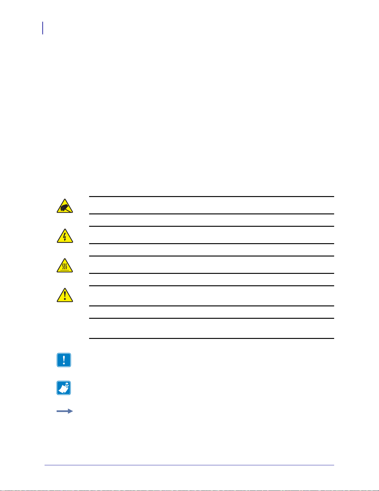
Caution • Warns you of the potential for electrostatic discharge.
Caution • Warns you of a potential electric shock situation.
Caution • Warns you of a situation where excessive heat could cause a burn.
Caution • Advises you that failure to take or avoid a specific action could result in physical
harm to you.
Caution • (No icon) Advises you that failure to take or avoid a specific action could result in
physical harm to the hardware.
Important • Advises you of informatio n that is essential to complete a task.
Note • Indicates neutral or positive information that emphasizes or supplements important
points of the main text.
Example • Provides an example, often a scenario, to better clarify a section of text.
13290L-004 Rev. A S4M User Guide 6/15/09
Page 13
About This Document
2
1
Document Conventions
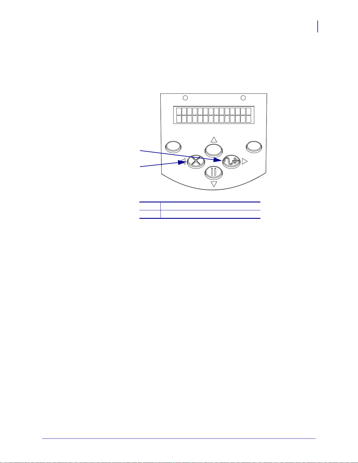
Illustration Callouts Callouts are used when an illustration contains information that needs
to be labeled and described. A table that contains the labels and descriptions follows the
graphic. Figure 1 provides an example.
Figure 1 • Sample Figure with Callouts
POWER ALERT
13
MENU
FEED button
1
CANCEL button
2
ENTER
CANCEL FEED
PAUSE
6/15/09 S4M User Guide 13290L-004 Rev. A
Page 14

About This Document
Notes • ___________________________________________________________________
__________________________________________________________________________
__________________________________________________________________________
__________________________________________________________________________
__________________________________________________________________________
__________________________________________________________________________
__________________________________________________________________________
__________________________________________________________________________
__________________________________________________________________________
__________________________________________________________________________
14
Document Conventions
13290L-004 Rev. A S4M User Guide 6/15/09
Page 15

1
Introduction
This section shows the operational controls and location of major components used when
loading media and ribbon. Other features of the printer are discussed.
Contents
External View. . . . . . . . . . . . . . . . . . . . . . . . . . . . . . . . . . . . . . . . . . . . . . . . . . . . . . . . . . 16
Control Panel . . . . . . . . . . . . . . . . . . . . . . . . . . . . . . . . . . . . . . . . . . . . . . . . . . . . . . . . . . 17
Control Panel LCD. . . . . . . . . . . . . . . . . . . . . . . . . . . . . . . . . . . . . . . . . . . . . . . . . . . . 18
Control Panel Buttons . . . . . . . . . . . . . . . . . . . . . . . . . . . . . . . . . . . . . . . . . . . . . . . . . 18
Control Panel Lights. . . . . . . . . . . . . . . . . . . . . . . . . . . . . . . . . . . . . . . . . . . . . . . . . . . 20
Printer Media Compartment. . . . . . . . . . . . . . . . . . . . . . . . . . . . . . . . . . . . . . . . . . . . . . . 21
Printer Language Modes . . . . . . . . . . . . . . . . . . . . . . . . . . . . . . . . . . . . . . . . . . . . . . . . . 22
Firmware Downloads. . . . . . . . . . . . . . . . . . . . . . . . . . . . . . . . . . . . . . . . . . . . . . . . . . 22
New or Modified Commands . . . . . . . . . . . . . . . . . . . . . . . . . . . . . . . . . . . . . . . . . . . . 22
Additional Printer Language Information . . . . . . . . . . . . . . . . . . . . . . . . . . . . . . . . . . . 22
6/15/09 S4M User Guide 13290L-004 Rev. A
Page 16
Introduction
1
2
Front
Rear
4
5
3
16
External View
External View
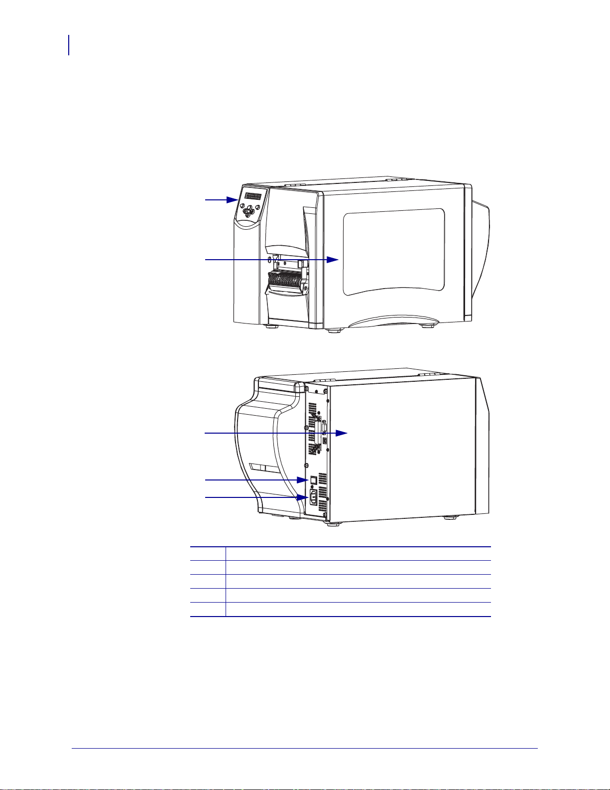
Figure 2 shows the outside of the printer.
Figure 2 • Exterior of Printer
Control panel
1
Media door
2
Electronics cover
3
Power switch (O = off, I = on)
4
AC power connector
5
13290L-004 Rev. A S4M User Guide 6/15/09
Page 17
Control Panel
3
5
6
7
8
9
2 1
4
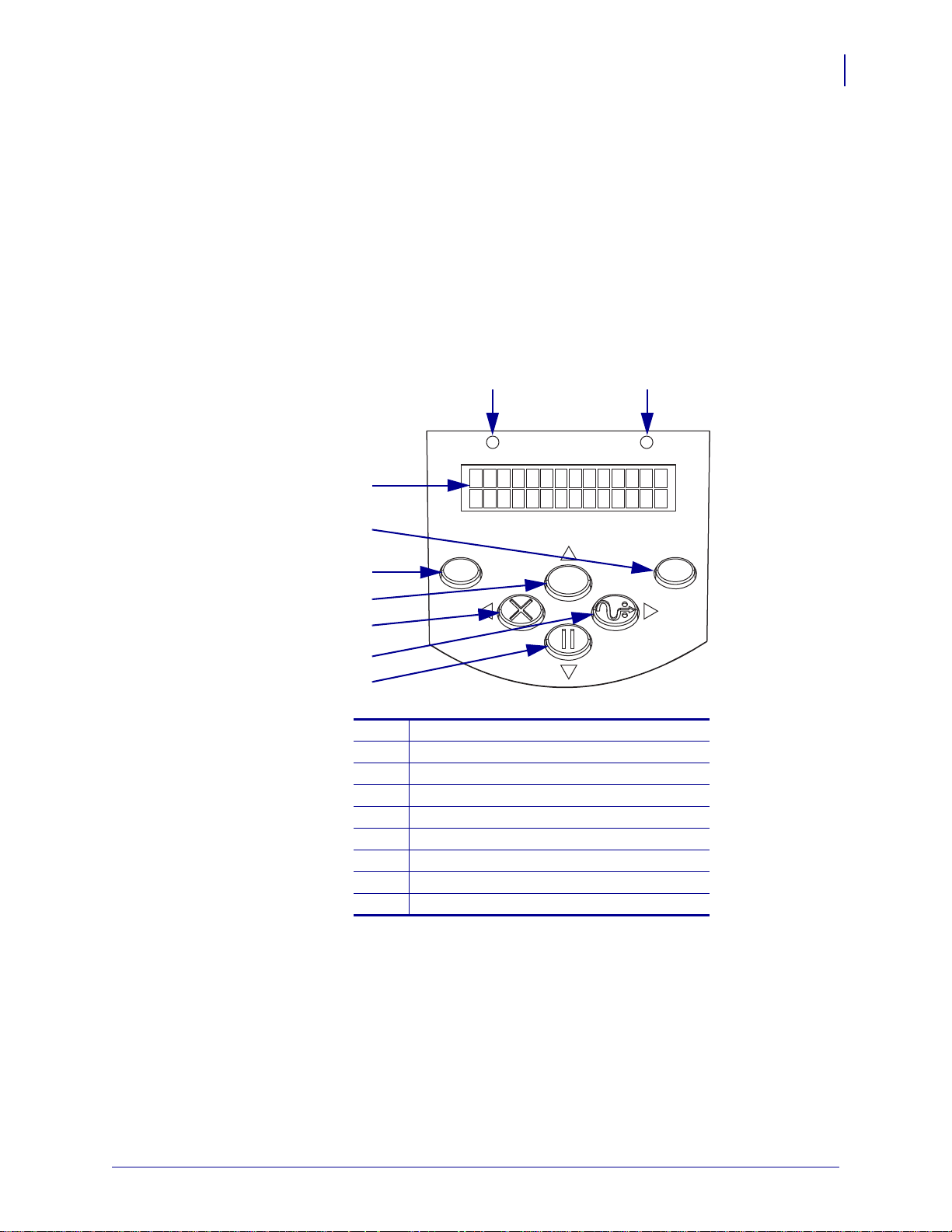
All controls and indicators for the printer are located on the control panel (Figure 3).
•The control panel Liquid Crystal Display (LCD) shows the operating status and printer
parameters.
•The control panel buttons are used to cont rol the printer operations and to set parameters.
•The control panel lights (LEDs) show the printer’s operating status or indicate which
control panel buttons are active.
Figure 3 • Location of Control Panel Buttons and Lights
POWER ALERT
Introduction
Control Panel
17
MENU
CANCEL FEED
ALERT light
1
POWER light
2
LCD
3
ENTER button
4
MENU button
5
Up arrow button
6
CANCEL or Left Arrow button
7
FEED or Right Arrow button
8
PAUSE or Down Arrow button
9
ENTER
PAUSE
6/15/09 S4M User Guide 13290L-004 Rev. A
Page 18
18
1
2
Introduction
Control Panel
Control Panel LCD
The control panel LCD functions differently in different printer modes.
•In Operating mode, the LCD displays the printer’s status, sometimes in conjunction with
a control panel light (see Contr ol Pan el Lights on page 20). When the printer is receiving
data, the control panel shows the word
spaces.
•In Pause mode, the printer stops printing temporarily.
•In Setup mode, you can use the control panel LCD to view or modify printer parameters
(see Control Panel Parameters on page 72).
•In Error mode, the LCD may display an alert or error message (see LCD Error Messages
on page 101).
Control Panel Buttons
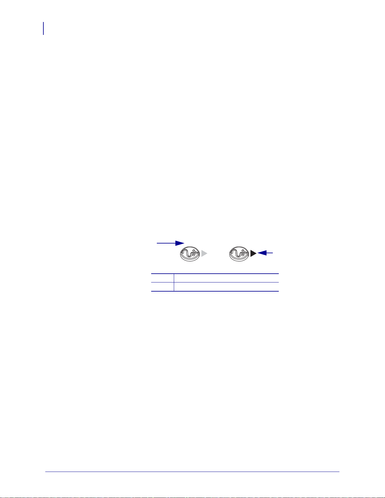
The printer has six basic control buttons on the control panel. Some of these buttons also
function as navigational keys when the printer is in Setup mode. The current function of a
particular button is determined by which light is illuminated next to it (Figure 4).
DATA and cycles through a series of dots and
Figure 4 • Example of Active Control Panel Buttons
FEED FEED
FEED active
1
Right arrow active
2
Table 1 describes the function of each button. The
active when the printer is in normal operating mode.
MENU, PAUSE, and FEED buttons are
13290L-004 Rev. A S4M User Guide 6/15/09
Page 19
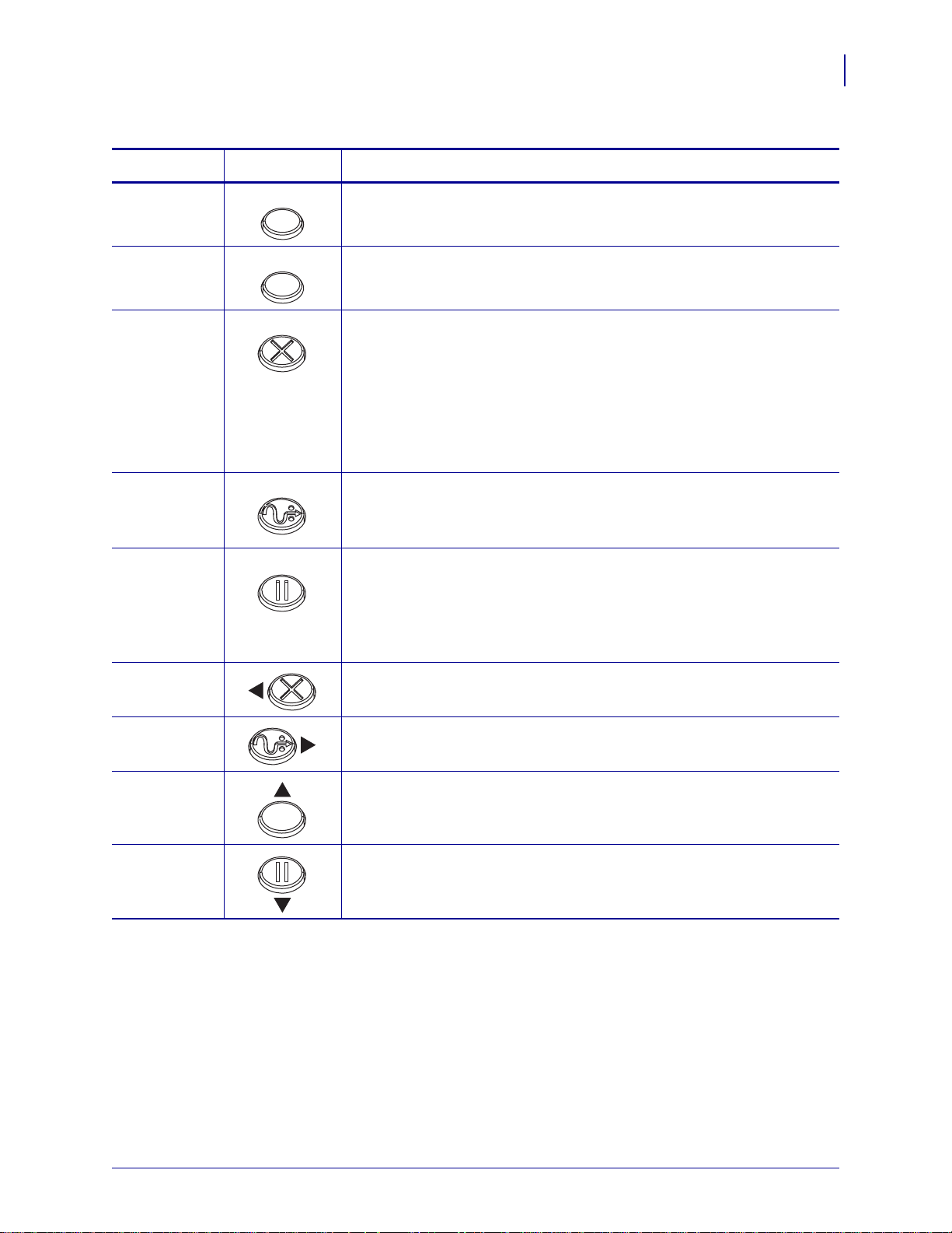
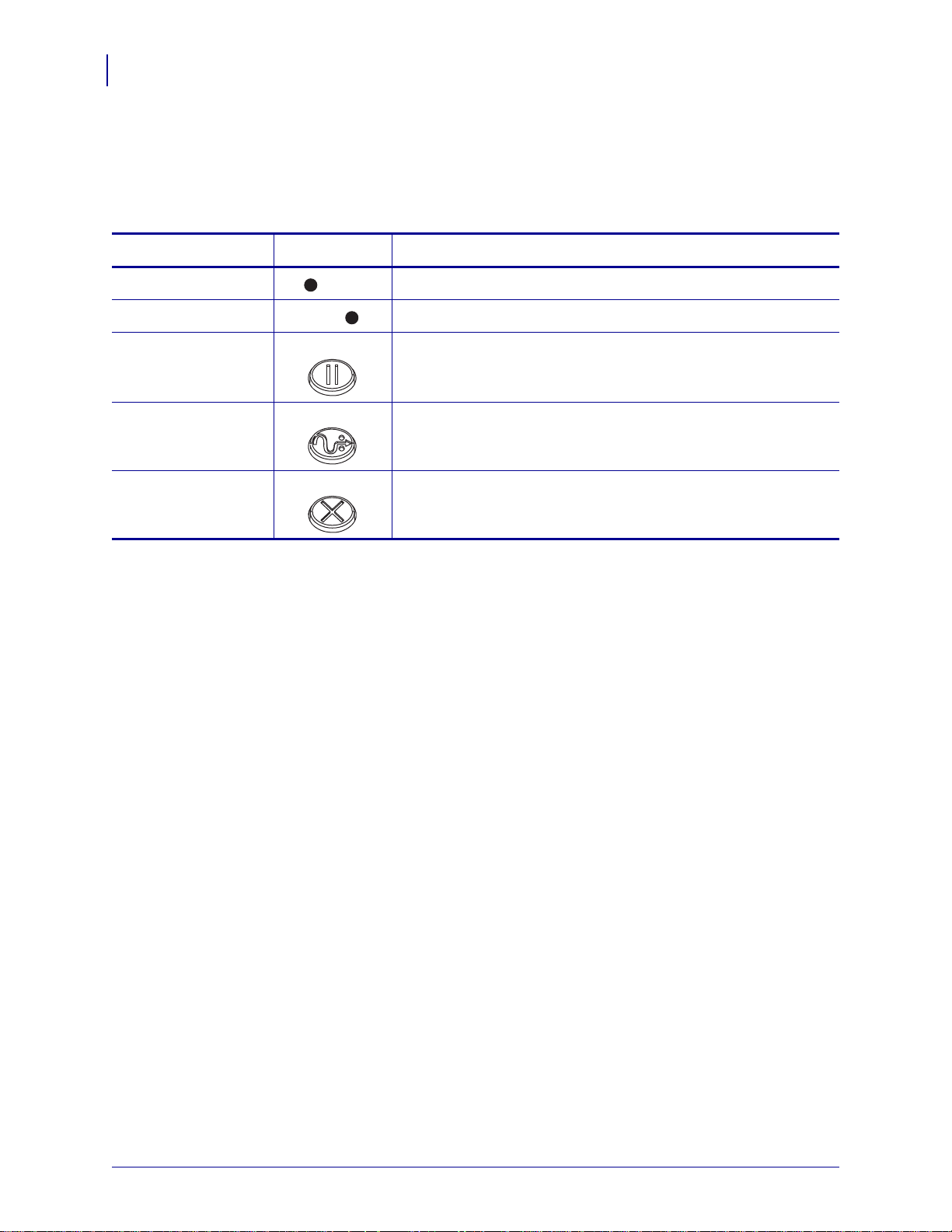
Table 1 • Control Panel Buttons
MENU
ENTER
Introduction
Control Panel
19
Button
MENU
ENTER
CANCEL
FEED
PAUSE
Left Arrow
Appearance
CANCEL
FEED
PAUSE
Function/Description
Enters and exits Setup mode.
If a parameter or option in Setup mode needs to be selected, pressing
ENTER selects the item. This button is active only when necessary.
CANCEL
functions only in Pause mode. Pressing CANCEL once has these
effects:
• Cancels the label format that is currently printing.
• If no label format is printing, the next one to be printed is canceled.
• If no label formats are waiting to be printed,
CANCEL is ignored.
To clear the printer’s entire label format memory, press and hold
CANCEL.
Advances a blank label.
• If the printer is idle or paused, the label is fed immediately.
• If the printer is printing, the label is fed after printing finishes.
Stops and restarts the printing process or removes error messages and
clears the LCD. When the printer is paused, the PAUSE light blinks.
• If the printer is idle, it enters Pause mode immediately.
• If the printer is printing, the label is completed before the printer
pauses.
When in Setup mode, scrolls the LCD to the previous parameter.
Right Arrow
Up Arrow
Down Arrow
When in Setup mode, scrolls the LCD to the next parameter.
When in Setup mode, increases values or scrolls to the next option.
When in Setup mode, decreases values or scrolls to the previous option.
6/15/09 S4M User Guide 13290L-004 Rev. A
Page 20
20
ER
A
Introduction
Control Panel
Control Panel Lights
Table 2 describes lights on the control panel that indicate different printer conditions.
Table 2 • Control Panel Lights
Light
POWER Indicates that the printer is on.
ALERT In an error or alert situation, the ALERT light flashes.
PAUSE (part of the
Appearance
POW
LERT
PAUSE
PAUSE button)
FEED (part of the
FEED
FEED button)
CANCEL (part of
CANCEL button)
the
CANCEL
Function/Description
Flashes when the printer is in Pause mo de unless the printer enters
Setup mode and the down arrow becomes active.
On during normal printer operation, indicati ng that t he print er can
feed a blank label.
On when canceling a label format is a valid option.
13290L-004 Rev. A S4M User Guide 6/15/09
Page 21
Printer Media Compartment
79
4
5
3
2
10 8
1
11
6
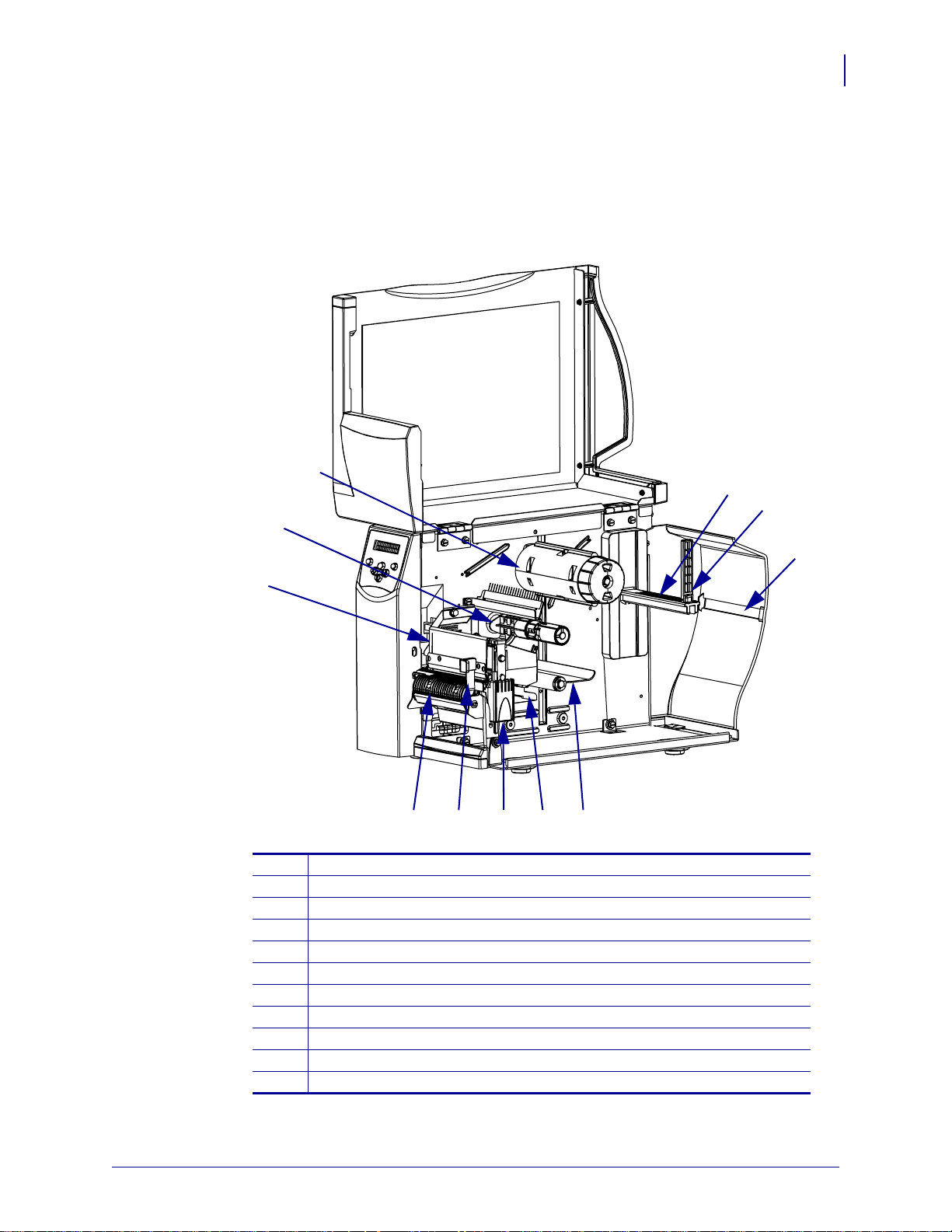
Figure 5 shows a simplified view of the media compartment of your printer. Depending on
installed options, your printer may look slightly different.
Figure 5 • Media Compartment
Introduction
Printer Media Compartment
21
Printhead assembly
6/15/09 S4M User Guide 13290L-004 Rev. A
1
Ribbon supply spindle*
2
Ribbon take-up spindle*
3
Media supply hanger
4
Media supply guide
5
Fanfold media slot
6
Dancer assembly
7
Media guide
8
Printhead release latch
9
Peel release lever**
10
Peel assembly**
11
* Present only on printers that have the Thermal Transfer option installed.
** Present only on printers that have the Peel option installed.
Page 22

Introduction
22
Printer Language Modes
Printer Language Modes
Depending on how your printer was ordered, it came from the factory with firmware that
operates in or allows you to use certain commands for one of the following printer languages:
• Zebra Programming Language (ZPL
•Eltron
• Datamax® Programming Language (APL-D™)
•Intermec
Firmware Downloads
You may download S4M firmware to the printer at any time to change from one printer
language to another. For the latest firmware versions and instructions for downloading them,
go to http://www.zebra.com/firmware.
Note • When the printer changes from one printer language to another, error messages may
appear on the LCD, and some control panel lights may activate in error mode. You may
ignore these error messages and lights. When the firmware download is complete, reboot the
printer and load printer defaults to return the printer to Operating mode.
®
Programming Language (EPL™)
®
®
Printer Language (APL-I™)
)
New or Modified Commands
See ZPL II Commands on page 131 for ZPL II commands that changed or that were added
specifically for this printer.
Additional Printer Language Information
The following manuals contain specific information about the different printer language
modes. Copies of these manuals are on the CD that came with your printer and at
http://www.zebra.com/manuals.
®
•ZPL II
• EPL2™ Programming Guide
• APL-D™ Reference Guide
• APL-I™ Reference Guide
Programming Guide
13290L-004 Rev. A S4M User Guide 6/15/09
Page 23

2
Printer Setup
This section provides the tasks that you must complete and the issues that you must consider
before you load and configure your printer.
Contents
Before You Begin. . . . . . . . . . . . . . . . . . . . . . . . . . . . . . . . . . . . . . . . . . . . . . . . . . . . . . . 24
Handling the Printer . . . . . . . . . . . . . . . . . . . . . . . . . . . . . . . . . . . . . . . . . . . . . . . . . . . . . 25
Unpack and Inspect the Printer . . . . . . . . . . . . . . . . . . . . . . . . . . . . . . . . . . . . . . . . . . 25
Store the Printer. . . . . . . . . . . . . . . . . . . . . . . . . . . . . . . . . . . . . . . . . . . . . . . . . . . . . . 25
Ship the Printer . . . . . . . . . . . . . . . . . . . . . . . . . . . . . . . . . . . . . . . . . . . . . . . . . . . . . . 25
Select a Site for the Printer . . . . . . . . . . . . . . . . . . . . . . . . . . . . . . . . . . . . . . . . . . . . . . . 26
Select a Surface. . . . . . . . . . . . . . . . . . . . . . . . . . . . . . . . . . . . . . . . . . . . . . . . . . . . . . 26
Provide Proper Operating Conditions . . . . . . . . . . . . . . . . . . . . . . . . . . . . . . . . . . . . . 26
Allow Proper Space . . . . . . . . . . . . . . . . . . . . . . . . . . . . . . . . . . . . . . . . . . . . . . . . . . . 26
Provide a Data Source. . . . . . . . . . . . . . . . . . . . . . . . . . . . . . . . . . . . . . . . . . . . . . . . . 26
Provide a Power Source . . . . . . . . . . . . . . . . . . . . . . . . . . . . . . . . . . . . . . . . . . . . . . . 26
Select a Data Communication Interface. . . . . . . . . . . . . . . . . . . . . . . . . . . . . . . . . . . . . . 27
Data Cables and Wireless Cards. . . . . . . . . . . . . . . . . . . . . . . . . . . . . . . . . . . . . . . . . 28
Connect the Printer to the Computer or Network. . . . . . . . . . . . . . . . . . . . . . . . . . . . . 28
Connect the Printer to a Power Source . . . . . . . . . . . . . . . . . . . . . . . . . . . . . . . . . . . . . . 30
Power Cord Specifications. . . . . . . . . . . . . . . . . . . . . . . . . . . . . . . . . . . . . . . . . . . . . . 31
Types of Media. . . . . . . . . . . . . . . . . . . . . . . . . . . . . . . . . . . . . . . . . . . . . . . . . . . . . . . . . 32
Ribbon Overview . . . . . . . . . . . . . . . . . . . . . . . . . . . . . . . . . . . . . . . . . . . . . . . . . . . . . . . 34
When to Use Ribbon . . . . . . . . . . . . . . . . . . . . . . . . . . . . . . . . . . . . . . . . . . . . . . . . . . 34
Coated Side of Ribbon. . . . . . . . . . . . . . . . . . . . . . . . . . . . . . . . . . . . . . . . . . . . . . . . . 34
6/15/09 S4M User Guide 13290L-004 Rev. A
Page 24

Printer Setup
24
Before You Begin
Before You Begin
Review this checklist, and resolve any issues before you set up or use your printer.
Unpack and Inspect the Printer Have you unpacked the printer and inspected it for
Select a Site Have you selected an appropriate location for the printer? If y ou have no t,
Connect to a Data Source Have you determined how the printer will connect to a
Attach a Power Cord Do you have the correct power cord for your printer? If you are
Select Media Do you have the correct media for your application? If you are unsure,
Select Ribbon Do you need to use ribbon, and is the appropriate ribbon available, if
damage? If you have not, see Unpack and Inspect the Printer on page 25.
see Select a Site for the Printer on page 26.
data source (usually a computer)? For more information, see Select a Data
Communication Interface on page 27.
unsure, see Power Cord Specifications on page 31. To attach the power cord and connect
the printer to a power source, see Connect the Printer to a Power Source on page 30.
see Types of Media on page 32.
needed? If you are unsure, see Ribbon Overview on page 34.
13290L-004 Rev. A S4M User Guide 6/15/09
Page 25

Handling the Printer
This section describes how to handle your printer.
Unpack and Inspect the Printer
When you receive the printer, immediately unpack it and inspect for shipping damage.
• Save all packing materials.
• Check all exterior surfaces for damage.
• Raise the media door, and inspect the media compartment for damage to components.
If you discover shipping damage upon inspection:
• Immediately notify the shipping company and file a damage report.
• Keep all packaging material for shipping company inspection.
• Notify your authorized Zebra reseller
Important • Zebra Technologies Corporation is not responsible for any damage incurred
during the shipment of the equipment and will not repair this damage under warranty.
Printer Setup
Handling the Printer
25
Store the Printer
If you are not placing the printer into immediate operation, repackage it using the original
packing materials. You may store the printer under the conditions shown in Table 3.
Temperature Relative Humidity
–40°F to 140°F (–40° to 60°C) 5% to 85% non-condensing
Ship the Printer
If you must ship the printer:
• Turn off (O) the printer, and disconnect all cables.
• Remove any media, ribbon, or loose objects from the printer interior.
• Close the printhead.
• Carefully pack the printer into the original container or a suitable alternate container to
avoid damage during transit. A shipping container can be purchased from Zebra if the
original packaging has been lost or destroyed.
Table 3 • Storage Temperature and Humidity
6/15/09 S4M User Guide 13290L-004 Rev. A
Page 26
Printer Setup
26
Select a Site for the Printer
Select a Site for the Printer
Consider the following when selecting an appropriate location for your printer.
Select a Surface
Select a solid, level surface of sufficient size and strength to accommodate the printer and
other equipment (such as a computer), if necessary. The choices include a table, countertop,
desk, or cart. For the printer’s weight and dimensions, see General Specifications on page 126.
Provide Proper Operating Conditions
This printer is designed to function in a wide range of environmental and electrical conditions,
including a warehouse or factory floor. For more information on the required conditions, see
General Specifications on page 126.
Table 4 shows the temperature and relative humidity requirements for the printer when it is
operating.
Table 4 • Operating Temperature and Humidity
Mode Temperature Relative Humidity
Thermal Transfer 40° to 105°F (5° to 40°C) 20 to 85% non-condensing.
Direct Thermal 32° to 105°F (0° to 40°C) 20 to 85% non-condensing
Allow Proper Space
The printer should have enough space around it for you to be able to open the media door. To
allow for proper ventilation and cooling, leave open space on all sides of the printer.
Caution • Do not place any padding or cushioning material behind or under the printer
because this restricts air flow and could cause the printer to overheat.
Provide a Data Source
If the printer will be located away from the data source (such as a computer), the selected site
must provide the appropriate connections to that data source. For more information on the
types of communication interfaces and their limitations, see Select a Data Communication
Interface on page 27.
Provide a Power Source
Place the printer within a short distance of a power outlet that is easily accessible.
13290L-004 Rev. A S4M User Guide 6/15/09
Page 27

Select a Data Communication Interface
Select a Data Communication Interface
Table 5 provides basic information about data communication interfaces that you can use to
connect your printer to a computer. Y ou ma y send label format s to the prin ter through any data
communication interface that is available. Select an interface that is supported by both your
printer and your computer or your Local Area Network (LAN).
Table 5 • Characteristics of the Data Communication Interfaces
Standard or
Interface
RS-232 Serial Standard • Maximum cable length of 50 ft (15.24 m).
Optional on
Printer
Characteristics
• You may need to change printer parameters to match the host
computer.
• You need to use a null-modem adaptor to connect to the printer
if using a standard modem cable.
Printer Setup
27
IEEE 1284
Bidirectional Parallel
Standard • Maximum cable length of 10 ft (3 m).
• Recommended cable length of 6 ft (1.83 m).
• An Ethernet print server (if installed) takes up or covers this
port on the printer.
• No printer parameter changes required to match the host
computer.
USB Standard • Maximum cable length of 16.4 ft (5 m).
• No printer parameter changes required to match the host
computer.
Internal wired
Ethernet print server
Optional • Can print to the printer from any computer on your LAN.
• Can communicate with the printer through the printer’s web
pages when in ZPL mode.
• Computer must be equipped with an Ethernet board.
• The printer must be configured to use your LAN.
Wireless Ethernet
print server
Optional • Can print to the printer from any computer on your Wireless
Local Area Network (WLAN).
• Can communicate with the printer through the printer’s web
pages when in ZPL mode.
• The printer must be configured to use your WLAN.
6/15/09 S4M User Guide 13290L-004 Rev. A
Page 28

Printer Setup
28
Select a Data Communication Interface
Data Cables and Wireless Cards
You must supply all data cables or wireless cards for your application.
Data Cables Ethernet cables do not require sh ielding, but all o ther data cabl es must be fully
shielded and fitted with metal or metallized connector shells. Unshielded data cables may
increase radiated emissions above the regulated limits.
To minimize electrical noise pickup in the cable:
• Keep data cables as short as possible.
• Do not bundle the data cables tightly with the power cords.
• Do not tie the data cables to power wire conduits.
Wireless Cards For supported wireless cards, refer to the ZebraNet Wireless User Guide. A
copy of the manual is available at http://www.zebra.com/manuals or on the user CD that came
with your printer.
Connect the Printer to the Computer or Network
Table 6 shows how to connect the different types of data cables to your printer and computer.
The connectors on the back of your computer may be in different locations than on the sample
computer shown in this section.
Caution • Ensure that the printer power is off (O) before connecting data communications
cables. Connecting a data communications cable while the power is on (
printer.
I) may damage the
Table 6 • Connecting the Printer to a Computer or Network
Interface Connection and Configuration
RS-232 Serial The baud rate, number of data and stop bits, the parity, and the
XON/XOFF or DTR control must match those of the host computer. See
Control Panel Param eters on page 72 to view or change these parameters.
IEEE 1284
Bidirectional
No additional configuration is necessary. An Ethernet print server (if
installed) takes up or covers this port on the printer.
Parallel
USB No additional configuration is necessary.
Caution • Be careful not to plug the USB cable into the wired Ethernet
print server connector on the printer because doing so will damage the
connector.
13290L-004 Rev. A S4M User Guide 6/15/09
Page 29
Select a Data Communication Interface
Table 6 • Connecting the Printer to a Computer or Network (Continued)
Interface Connection and Configuration
Printer Setup
29
Internal wired
Ethernet print
server
Wireless
Ethernet print
server
Refer to the ZebraNet 10/100 Print Server User and Reference Guide for
configuration instructions. A copy of this manual is available at
http://www.zebra.com/manuals or on the user CD that came with your
printer.
Note • To use this connection, you may need to remove a factory-
installed plug that is designed to keep someone from accidentally
plugging a USB connector into this port.
Refer to the ZebraNet Wireless User Guide for co nfig uration instructions.
A copy of this manual is available at http://www.zebra.com/manuals or on
the user CD that came with your printer.
6/15/09 S4M User Guide 13290L-004 Rev. A
Page 30
Printer Setup
1
30
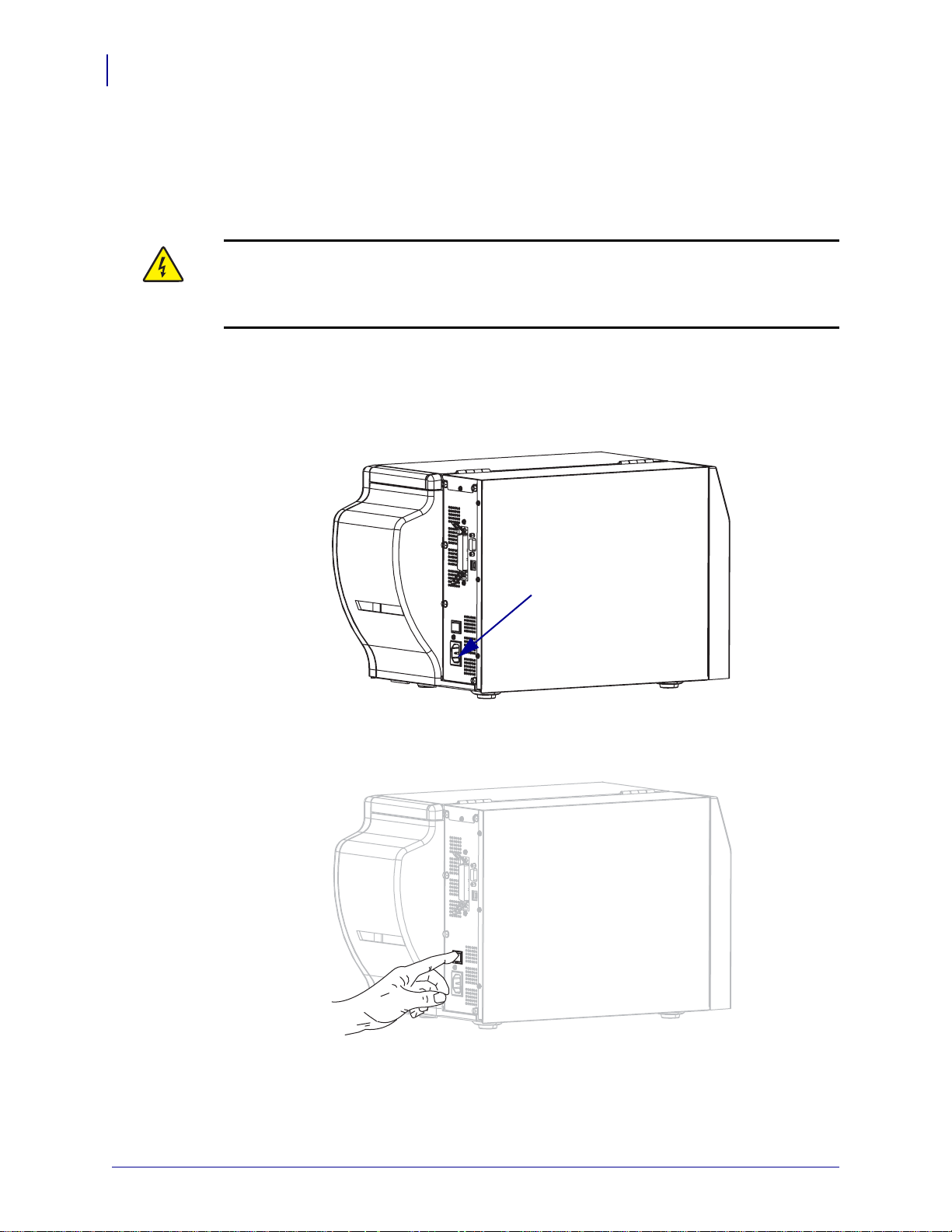
Connect the Printer to a Power Source
Connect the Printer to a Power Source
The AC power cord must have a three-prong female connector on one end that plugs into the
mating AC power connector at the rear of the printer. If a power cable was not included with
your printer, refer to Power Cord Specifications on page 31.
Caution • For personnel and equipment safety, always use an approved three-conductor
power cord specific to the region or country intended for installation. This cord must use an
IEC 320 female connector and the appropriate region-specific three-conductor grounded
plug configuration.
To connect the printer to a power source, complete these steps:
1. Toggle the printer power switch to the off (O) position.
2. Plug the power cord into the AC power connector (1) on the rear of the printer.
3. Plug the other end of the power cord into a power outlet near the printer.
4. Turn on (I) the printer.
The control panel LCD and lights activate, indicating that the printer is booting up.
13290L-004 Rev. A S4M User Guide 6/15/09
Page 31

Power Cord Specifications
3
1
2
4
Caution • For personnel and equipment safety, always use an approved three-conductor
power cord specific to the region or country intended for installation. This cord must use an
IEC 320 female connector and the appropriate region-specific, three-conductor grounded
plug configuration.
Depending on how your printer was ordered, a power cord may or may not be included. If one
is not included or if the one included is not suitable for your requirements, see Figure 6 and
refer to the following guidelines:
• The overall cord length must be less than 9.8 ft. (3 m).
• The cord must be rated for at least 10 A, 250 V.
• The chassis ground (earth) must be connected to e nsure safety and redu ce electromagnetic
interference.
Figure 6 • Power Cord Specifications
Printer Setup
Connect the Printer to a Power Source
31
AC power plug for your country—This should bear
1
the certification mark of at least one of the known
international safety organizations (Figure 7).
3-conductor HAR cable or other cable approved for
2
your country.
IEC 320 connector—This should bear the
3
certification mark of at least one of the known
international safety organizations (Figure 7).
Length ≤ 9.8 ft. (3 m). Rating 10 Amp, 250 VAC.
4
Figure 7 • International Safety Organization Certifications
6/15/09 S4M User Guide 13290L-004 Rev. A
Page 32

Printer Setup
32
Types of Media
Types of Media
Important • Zebra strongly recommends the use of Zebra-brand supplies for continuous
high-quality printing. A wide range of paper, polypropylene, polyester, and vinyl stock has
been specifically engineered to enhance t he p rint ing c apabi lities of the pri nter an d to pre vent
premature printhead wear. To purchase supplies, go to http://www.zebra.com/howtobuy.
Your printer can use various types of media:
• Standard media—Most standard media uses an adhesive backing that sticks individual
labels or a continuous length of labels to a liner.
• Tag stock—Tags are usually made from a heavy paper. Tag stock does not have adhesive
or a liner, and it is typically perforated between tags.
Table 7 describes roll and fanfold media. Roll media is loaded into the printer while fanfold
media may be located inside or outside of the printer.
Table 7 • Roll and Fanfold Media
Media Type How It Looks Description
Non-Continuous
Roll Media
Roll media is wound on a core that can be 1 in. to 3 in. (25 to
76 mm) in diameter. Individual labels are separated by one or
more of the following methods:
• Web media separates labels by gaps, ho les, or notches.
• Black mark media uses pre-printed black marks on the back
side of the media to indicate label separations.
• Perforated media has perforations that allow the labels or
tags to be separated from each other easily. The media may
also have black marks or other separations between labels
or tags.
13290L-004 Rev. A S4M User Guide 6/15/09
Page 33

Table 7 • Roll and Fanfold Media (Continued)
Media Type How It Looks Description
Printer Setup
Types of Media
33
Non-Continuous
Fanfold Media
Continuous
Roll Media
Fanfold media is folded in a zigzag pattern. Fanfold media can
have the same label separations as non-continuous roll media.
The separations would fall on or near the folds.
Roll media is wound on a core that can be 1 in. to 3 in. (25 to
76 mm) in diameter.
Continuous roll media does not have gaps, holes, notches , o r
black marks to indicate label separations. This allows the
image to be printed anywhere on the label. Sometimes a cutter
is used to cut apart individual labels.
6/15/09 S4M User Guide 13290L-004 Rev. A
Page 34

Printer Setup
Outside Inside
34
Ribbon Overview
Ribbon Overview
Note • This section applies only to printers that have the Thermal Transfer option installed.
Ribbon is a thin film that is coated on one side with wax, resin, or wax resin, which is
transferred to the media during the thermal transfer process. The media determines whether
you need to use ribbon and how wide the ribbon must be.
When ribbon is used, it must be as wide as or wider than the media being used. If the ribbon is
narrower than the media, areas of the printhead are unprotected and subject to premature wear.
When to Use Ribbon
Thermal transfer media requires ribbon for printing while direct thermal media does not.
To determine if ribbon must be used with a particular media, perform a media scratch test.
To perform a media scratch test, complete these steps:
1. Scratch the print surface of the media rapidly with your fingernail.
2. Did a black mark appear on the media?
If a black mark... Then the media is...
Does not appear on the media Thermal transfer. A ribbon is required.
Appears on the media Direct thermal. No ribbon is required.
Coated Side of Ribbon
Ribbon can be wound with the co ated si de on the i nside or outsi de ( Figure 8). This printer can
only use ribbon that is coated on t he outside. If you are unsure which side of a particular roll of
ribbon is coated, perform an adhesive test or a ribbon scratch t est to determine which side is
coated.
Figure 8 • Ribbon Coated on Outside or Inside
13290L-004 Rev. A S4M User Guide 6/15/09
Page 35

Adhesive Test
If you have labels available, perform the adhesive test to determine which side of a ribbon is
coated. This method works well for ribbon that is already installed.
To perform an adhesive test, complete these steps:
1. Peel a label from its liner.
2. Press a corner of the sticky side of the label to the outer surface of the roll of ribbon.
3. Peel the label off of the ribbon.
4. Observe the results. Did flakes or particles of ink from the ribbon adhere to the label?
If ink from the ribbon... Then...
Adhered to the label The ribbon is coated on the outside and can be used in
this printer.
Did not adhere to the label The ribbon is coated on the inside and cannot be used in
this printer. To verify this, repeat the test on the other
surface of the roll of ribbon.
Printer Setup
Ribbon Overview
35
Ribbon Scratch Test
Perform the ribbon scratch test when labels are unavailable.
To perform a ribbon scratch test, complete these steps:
1. Unroll a short length of ribbon.
2. Place the unrolled section of ribbon on a piece of paper with the outer surface of the
ribbon in contact with the paper.
3. Scratch the inner surface of the unrolled ribbon with your fingernail.
4. Lift the ribbon from the paper.
5. Observe the results. Did the ribbon leave a mark on the paper?
If the ribbon... Then...
Left a mark on the paper The ribbon is coated on the outer surface.
Did not leave a mark on the
paper
The ribbon is coated on the inner surface and cannot be
used in this printer. To verify this, repeat the test on the
other surface of the roll of ribbon.
6/15/09 S4M User Guide 13290L-004 Rev. A
Page 36

Printer Setup
Notes • ___________________________________________________________________
__________________________________________________________________________
__________________________________________________________________________
__________________________________________________________________________
__________________________________________________________________________
__________________________________________________________________________
__________________________________________________________________________
__________________________________________________________________________
__________________________________________________________________________
__________________________________________________________________________
36
Ribbon Overview
13290L-004 Rev. A S4M User Guide 6/15/09
Page 37

3
Operations
This section provides the procedures for loading and calibrating th e pri nt er.
Note • Complete the tasks and resolve the issues in Printer Setup on page 23 before
operating the printer.
Contents
Print Modes and Printer Options . . . . . . . . . . . . . . . . . . . . . . . . . . . . . . . . . . . . . . . . . . . 38
Print Mode Descriptions and Printer Requirements. . . . . . . . . . . . . . . . . . . . . . . . . . . 38
Media Paths. . . . . . . . . . . . . . . . . . . . . . . . . . . . . . . . . . . . . . . . . . . . . . . . . . . . . . . . . 38
Start a Roll of Media. . . . . . . . . . . . . . . . . . . . . . . . . . . . . . . . . . . . . . . . . . . . . . . . . . . 39
Insert Media into the Printer. . . . . . . . . . . . . . . . . . . . . . . . . . . . . . . . . . . . . . . . . . . . . 40
Load Media in Tear-Off Mode. . . . . . . . . . . . . . . . . . . . . . . . . . . . . . . . . . . . . . . . . . . . . . 42
Load Media in Peel-Off Mode . . . . . . . . . . . . . . . . . . . . . . . . . . . . . . . . . . . . . . . . . . . . . 45
Load Media in Cutter Mode . . . . . . . . . . . . . . . . . . . . . . . . . . . . . . . . . . . . . . . . . . . . . . . 50
Load Ribbon. . . . . . . . . . . . . . . . . . . . . . . . . . . . . . . . . . . . . . . . . . . . . . . . . . . . . . . . . . . 53
Remove Used Ribbon . . . . . . . . . . . . . . . . . . . . . . . . . . . . . . . . . . . . . . . . . . . . . . . . . 57
Calibrate the Printer. . . . . . . . . . . . . . . . . . . . . . . . . . . . . . . . . . . . . . . . . . . . . . . . . . . . . 58
Auto Calibration . . . . . . . . . . . . . . . . . . . . . . . . . . . . . . . . . . . . . . . . . . . . . . . . . . . . . . 58
Manual Calibration. . . . . . . . . . . . . . . . . . . . . . . . . . . . . . . . . . . . . . . . . . . . . . . . . . . . 58
Select or Adjust the Media Sensors. . . . . . . . . . . . . . . . . . . . . . . . . . . . . . . . . . . . . . . . . 59
Select the Transmissive Sensor. . . . . . . . . . . . . . . . . . . . . . . . . . . . . . . . . . . . . . . . . . 59
Adjust the Reflective Sensor . . . . . . . . . . . . . . . . . . . . . . . . . . . . . . . . . . . . . . . . . . . . 59
Adjust Printhead Pressure . . . . . . . . . . . . . . . . . . . . . . . . . . . . . . . . . . . . . . . . . . . . . . . . 61
6/15/09 S4M User Guide 13290L-004 Rev. A
Page 38

Operations
38
Print Modes and Printer Options
Print Modes and Printer Options
The printer can use different print modes and options for label removal (Table 8). Use a print
mode that matches the media being used and the printer optio ns avail able. For more
information on the types of media, see Types of Media on page 32. To select a print mode, see
Select the Label Removal Method on page 74.
Print Mode Descriptions and Printer Requirements
Table 8 • Print Modes and Printer Options
Print Mode When to Use/Printer Options Required Printer Actions
Tear-Off
(default setting)
Peel-Off Use only if the printer has the Peel-Off
Cutter Use if the printer has a cutter option when
Use for most applications. This mode can
be used with any printer options and most
media types.
option.
you want the labels to be cut apart.
Media Paths
Table 9 shows the media paths for print mode and printer option combinations using roll
media. Fanfold media uses the same print modes and printer options as roll media.
Table 9 • Media Paths for Print Modes with Various Printer Options
Print Mode Printer Option
Tear-Off Printers with any
printer options can
use Tear-Off mode
The printer prints label formats as it
receives them. The printer operator can tear
off the printed labels any time after they
print.
The printer peels the label from the liner
during printing and then pauses until the
label is removed. The liner exits the front of
the printer.
The printer prints a label and then cuts it
free.
Media Path
Red solid lines = media, Blue dotted lines = backing only
13290L-004 Rev. A S4M User Guide 6/15/09
Page 39

Operations
Print Modes and Printer Options
Table 9 • Media Paths for Print Modes with Various Printer Options (Continued)
39
Print Mode Printer Option
Peel-Off Peel, Liner take-up,
or Rewind
Cutter Cutter (shown with
an optional catch
tray)
Red solid lines = media, Blue dotted lines = backing only
Media Path
Start a Roll of Media
Exposed media may become dirty when han dled or stored. To start a roll of media, remove and
discard one full revolution of labels or tags and any liner.
Remove all labels that are held by
adhesives or tape.
Labels Tag Stock
Detach all exposed tags.
6/15/09 S4M User Guide 13290L-004 Rev. A
Page 40

Operations
40
Print Modes and Printer Options
Insert Media into the Printer
Roll Media
To insert roll media, complete these steps:
This section shows how to insert roll or fanfold media in to the printer. Fanfold medi a is loaded
the same way as roll media, except the media is stored outside of the printer.
1. Flip down the media supply guide.
2. Place the roll of media on the media supply hanger. Push the roll as far back as it will go.
3. Flip up the media supply guide, and then slide it in until it touches, but does not restrict,
the edge of the roll.
4. Continue with the media loading procedure for the desired print mode.
13290L-004 Rev. A S4M User Guide 6/15/09
Page 41

Fanfold Media
To insert fanfold media, complete these steps:
1. Flip down the media supply guide.
2. Insert the fanfold media through the fanfold media slot on the rear of the printer.
Operations
Print Modes and Printer Options
41
3. Drape the media over the media supply hanger.
4. Flip up the media supply guide, and then slide it in until it touches, but does not restrict,
the edge of the media.
5. Continue with the media loading procedure for the desired print mode.
6/15/09 S4M User Guide 13290L-004 Rev. A
Page 42

Operations
1
2
5678
4
3
1
2
5678
4
3
42
Load Media in Tear-Off Mode
Load Media in Tear-Off Mode
Figure 9 shows roll and fanfold media loaded in Tear-Off mode, which is the default print
mode.
Roll Media
Figure 9 • Tear-Off Mode
Fanfold Media
Printhead assembly
1
Transmissive sensor
2
Media supply guide
3
Media supply hanger
4
Caution • While performing any tasks near an open printhead, remove all rings, watches,
hanging necklaces, identification badges, or other metallic objects that could touch the
printhead. You are not required to turn off the printer power when working near an open
printhead, but Zebra recommends it as a precaution. If you turn off the power, you will lose
all temporary settings, such as label formats, and you must reload them before you resume
printing.
To load media in Tear-Off Mode, complete these steps:
1. Set the printer to Tear-Off mode. See Select the Label Removal Method on page 74 for
Dancer
5
Media guide
6
Printhead release latch
7
Printed label
8
instructions.
2. Insert media into the printer. See Inse rt Med ia in to the Printer on page 40 for instructions.
13290L-004 Rev. A S4M User Guide 6/15/09
Page 43

Operations
123
Load Media in Tear-Off Mode
3. Press the printhead release latch to open the printhead assembly. Lift the printhead until it
latches open.
4. Slide out the media guide.
43
5. Feed the media under the dancer assembly (1), through the slot in the transmissive
sensor (
2—standard transmissive sensor shown), and under the ribbon senso r (3).
6/15/09 S4M User Guide 13290L-004 Rev. A
Page 44

Operations
1
2
44
Load Media in Tear-Off Mode
6. Push the media to the back of the transmissive sensor (1). Slide in the media guide (2)
until it just touches the edge of the media.
7. Close the printhead assembly.
8. If the printer is paused (the PAUSE light is blinking), press PAUSE to enable printing.
13290L-004 Rev. A S4M User Guide 6/15/09
Page 45

Load Media in Peel-Off Mode
4
5
6
789
10
11
12
1
2
3
This section applies only if the Peel-Off option is installed (Figure 10).
The peel assembly consists of several spring-loaded rollers to ensure the proper roller
pressure. Use the peel release lever and your right hand to open and close the peel assembly.
Doing this will keep your fingers away from the rollers.
Caution • Do not use your left hand to assist in closing the peel assembly. The top edge of
the peel roller/assembly could pinch your fingers.
Figure 10 • Peel-Off Mode
Operations
Load Media in Peel-Off Mode
45
Peel lever
1
Tear-off /peel-off bar
2
Printhead assembly
3
Transmissive sensor
4
Media supply guide
5
Media supply hanger
6
6/15/09 S4M User Guide 13290L-004 Rev. A
Dancer
7
Media guide
8
Printhead release latch
9
Label liner
10
Peel assembly
11
Label
12
Page 46

Operations
46
Load Media in Peel-Off Mode
To load media in Peel-Off mode, complete these steps:
Caution • While performing any tasks near an open printhead, remove all rings, watches,
hanging necklaces, identification badges, or other metallic objects that could touch the
printhead. You are not required to turn off the printer power when working near an open
printhead, but Zebra recommends it as a precaution. If you turn off the power, you will lose
all temporary settings, such as label formats, and you must reload them before you resume
printing.
1. Press the printhead release latch to open the printhead assembly.
2. Lift the printhead until it latches open.
3. Slide out the media guide.
13290L-004 Rev. A S4M User Guide 6/15/09
Page 47

Operations
123
Load Media in Peel-Off Mode
4. Feed the media under the dancer assembly (1), through the slot in the transmissive
sensor (2—standard transmissive sensor shown), and under the ribbon sensor (
5. Push down the peel-off mechanism release lever to open the peel assembly.
3).
47
6. Pull approximately 18 in. (500 mm) of media through the front of the printer.
6/15/09 S4M User Guide 13290L-004 Rev. A
Page 48

Operations
1
2
1
2
48
Load Media in Peel-Off Mode
7. Remove the exposed labels so that only the liner remains.
8. Feed the liner over the tear-off/peel-off bar (1) and behind the peel assembly (2). Make
sure that the end of the liner falls outside of the printer.
9. Push the media to the back of the transmissive sensor (1). Slide in the media guide (2)
until it just touches the edge of the media.
13290L-004 Rev. A S4M User Guide 6/15/09
Page 49

Load Media in Peel-Off Mode
10. Close the printhead assembly.
11.
Caution • Use the peel release lever and your right hand to close the peel assembly.
Do not use your left hand to assist in closing. The top edge of the peel roller/assembly
could pinch your fingers.
Operations
49
Close the peel assembly using the peel-off mechanism release lever.
12.
Set the printer to Peel-Off mode. See Select the Label Removal Method on page 74 for
instructions.
13. If the printer is paused (the PAUSE light is blinking), press PAUSE to enable printing.
Peeling starts automatically.
6/15/09 S4M User Guide 13290L-004 Rev. A
Page 50

Operations
1
2
5678
4
3
9
50
Load Media in Cutter Mode
Load Media in Cutter Mode
Figure 9 shows roll and fanfold media loaded in Cutter mode.
Figure 11 • Cutter Mode
Printhead assembly
1
Transmissive sensor
2
Media supply guide
3
Media supply hanger
4
Dancer
5
Caution • While performing any tasks near an open printhead, remove all rings, watches,
hanging necklaces, identification badges, or other metallic objects that could touch the
printhead. You are not required to turn off the printer power when working near an open
printhead, but Zebra recommends it as a precaution. If you turn off the power, you will lose
all temporary settings, such as label formats, and you must reload them before you resume
printing.
Media guide
6
Printhead release latch
7
Cutter
8
Printed label
9
To load media in Cutter Mode, complete these steps:
1. Set the printer to Cutter mode. See Select the Label Removal Method on page 74 for
instructions.
2. Insert media into the printer. See Inse rt Med ia in to the Printer on page 40 for instructions.
13290L-004 Rev. A S4M User Guide 6/15/09
Page 51

Operations
4
123
Load Media in Cutter Mode
3. Press the printhead release latch to open the printhead assembly. Lift the printhead until it
latches open.
4. Slide out the media guide.
51
5.
Caution • The cutter blade is sharp. Do not touch or rub the blade with your fingers.
Feed the media under the dancer assembly (1), through the slot in the transmissive
sensor (
and through the cutter (
6/15/09 S4M User Guide 13290L-004 Rev. A
2—standard transmissive sensor shown), under the printhead-open sensor (3),
4).
Page 52

Operations
1
2
52
Load Media in Cutter Mode
6. Push the media to the back of the transmissive sensor (1). Slide in the media guide (2)
until it just touches the edge of the media.
7. Close the printhead assembly.
8. If the printer is paused (the PAUSE light is blinking), press PAUSE to enable printing.
13290L-004 Rev. A S4M User Guide 6/15/09
Page 53

Load Ribbon
1
4
3
2
Note • This section applies only to printers that have the Thermal Transfer option installed.
The ribbon supply spindle in your printer is a dual-tension variety. Most applications require
the spindle to be in the normal position. The lo w tension position is reco mmended only when a
narrow ribbon is used or if normal tension hampers the ribbon movement.
Always use ribbon that is wider than the media to protect the printhead from wear. For direct
thermal printing, do not load ribbon in the printer.
Figure 12 • Ribbon Path
Operations
Load Ribbon
53
Printhead assembly
1
Ribbon supply spindle
2
Ribbon take-up spindle
3
Tension blades
4
6/15/09 S4M User Guide 13290L-004 Rev. A
Page 54

54
1 2
Operations
Load Ribbon
Caution • While performing any tasks near an open printhead, remove all rings, watches,
hanging necklaces, identification badges, or other metallic objects that could touch the
printhead. You are not required to turn off the printer power when working near an open
printhead, but Zebra recommends it as a precaution. If you turn off the power, you will lose
all temporary settings, such as label formats, and you must reload them before you resume
printing.
To load ribbon, complete these steps:
1. Set the ribbon supply spindle for normal or low tension.
• T o pla ce th e ri bbon supp ly spi ndle in the normal position, firmly pull out the spindle
end cap until it extends and c licks in place , as sh own in Figure 13. Use this setting for
most applications.
• To place the ribbon supply spindle in the low-tension position, firmly push in the end
cap until it retracts and clicks in place, as shown in Figure 13. Use this setting when
using a narrow ribbon or if normal tension hampers ribbon movement.
Figure 13 • Ribbon Spindle—Normal and Low Tension
Normal Position (Spindle End Cap Extended)
1
Low-Tension Position (Spindle End Cap Retracted)
2
2. Press the printhead release latch to open the printhead assembly. Lift the printhead until it
latches open.
13290L-004 Rev. A S4M User Guide 6/15/09
Page 55

Operations
1
1
Load Ribbon
3. Orient the ribbon with the loose end unrolling clockwise.
4. Place the roll of ribbon on the ribbon supply spindle (1) and push it all the way back.
55
5. Pull the end of the ribbon under the printhea d assembly ( 1) and out the front of the printer.
6/15/09 S4M User Guide 13290L-004 Rev. A
Page 56

56
1
Operations
Load Ribbon
6. Close the printhead assembly.
7. Wind the ribbon clockwise onto the ribbon take-up spindle (1).
13290L-004 Rev. A S4M User Guide 6/15/09
Page 57

Remove Used Ribbon
1
1
2
Remove used ribbon from the ribbon take-up spindle each time you change the roll of ribbon
or when switching from thermal transfer mode to direct thermal mode.
To remove used ribbon, complete these steps:
1.
Caution • Do not cut the ribbon directly on the ribbon take-up spindle. Doing so may
damage the spindle.
If the ribbon has not run out, cut or break it before the ribbon take-up spindle (1).
Operations
Load Ribbon
57
To loosen the ribbon, squeeze it against the ribbon take-up spindle tension blades (1). At
2.
the same time, turn the ribbon take-up spindle release knob counterclockwise (
2).
The tension blades collapse into the ribbon take-up spindle, loosening the ribbon.
3. Slide the used ribbon off of the ribbon take-up spindle and discard.
6/15/09 S4M User Guide 13290L-004 Rev. A
Page 58

Operations
58
Calibrate the Printer
Calibrate the Printer
The printer can be set to calibrate automatically, or you can calibrate it manually.
Auto Calibration
When the control panel setting for automaticall y calibrat es on power up or when the printhead
is closed. During auto calibration, the printer determines the label length and sensor settings.
The results of the auto calibration are stored in the printer’s memory and are retained even if
printer power is removed. These parameters remain in effect until the next calibration is
performed.
Manual Calibration
Perform a media and ribbon sensor calibration to reset the sensitivity of the sensors so the
media and ribbon are detected more accurately. If you change the type of ribbon or media,
your printer may operate better if you perform this calibration.
For instructions, refer to Calibrate Media and Ribbon Sensors on page 85.
13290L-004 Rev. A S4M User Guide 6/15/09
Page 59

Select or Adjust the Media Sensors
1
This printer uses two types of media sensors: transmissive and reflective.
Select the Transmissive Sensor
The standard transmissive sensor (Figure 14) is in a fixed position and enabled from the
control panel. For more information about the operation of this sensor, see Select the Media
Sensor on page 74.
Figure 14 • Transmissive Sensor
Operations
Select or Adjust the Media Sensors
59
1
Adjust the Reflective Sensor
The reflective sensor is compatible with most types of media. W ith non-continuous media, the
reflective sensor detects the sta r t-of-label indicator (the notch, hole, black mark, or gap
between die-cut labels). With both continuous media and non-continuous media, the sensor
detects an out-of-paper condition. If you have difficulties with calibration while using this
sensor, use the transmissive sensor (see Select the Media Sensor on page 74).
Position the reflective sensor in the following way:
• directly under the notch, hole, or black mark with these types of labels
• anywhere along the width of the media if there is a gap between labels
• anywhere under the media for continuous media
The glow of the red light through the media may help you accurately positi on the senso r.
Standard transmissive sensor
6/15/09 S4M User Guide 13290L-004 Rev. A
Page 60

Operations
1
2
3
4
60
Select or Adjust the Media Sensors
Figure 15 • Adjusting the Reflective Sensor
Printhead assembly
1
Reflective sensor
2
Reflective sensor positioning lever
3
Printhead release latch
4
To adjust the reflective sensor, complete these steps:
1. See Figure 15. Press the printhead release latch.
2. Lift the printhead until it latches open.
3. Locate the reflective sensor positioning lever.
4. Move the reflective sensor positioning lever across the width of the media until the
reflective sensor aligns with the gap or notch.
5. Close the printhead assembly.
13290L-004 Rev. A S4M User Guide 6/15/09
Page 61

Adjust Printhead Pressure
1
2
You may need to adjust printhead pressure if printing is too light on one side, if you use thick
media, or if the media drifts from side to side during printing.
See Figure 16. The pressure adjustment dials have four possible settings designated by blocks
of increasing size embossed on the print mechanism. The smallest block (fully
counterclockwise) is considered position 1, and the largest block (fully clockwise) is
considered position 4.
Figure 16 • Printhead Pressure Adjustment Dials
Operations
Adjust Printhead Pressure
61
Outside dial
1
Inside dial
2
To set printhead pressure, complete these steps:
1. Use Table 10 to select the initial dial settings for your media.
Media Width
1 in. (25.4 mm)
2 in. (51 mm)
3 in. (76 mm)
3.5 in. and up (89 mm and up)
6/15/09 S4M User Guide 13290L-004 Rev. A
Table 10 • Printhead Pressure
Inside Dial Outside Dial
31
41
32
33
Page 62

Operations
62
Adjust Printhead Pressure
2. If necessary, adjust the pressure adjustment dials as follows:
If the media... Then...
Requires higher pressure to
Increase both dials one position.
print well
Shifts left while printing Increase the outside dial setting one position, or
decrease the inside dial setting one position.
Shifts right while printing Increase the inside dial setting one position, or
decrease the outside dial setting one position.
Prints too lightly on the left side
Increase the inside dial setting one position.
of the label.
Prints too lightly on the right
Increase the outside dial setting one position.
side of the label.
13290L-004 Rev. A S4M User Guide 6/15/09
Page 63

4
Configuration
This section discusses printer configuration settings and instructs you how to view or change
printer parameters through the control panel.
Contents
Setup Mode . . . . . . . . . . . . . . . . . . . . . . . . . . . . . . . . . . . . . . . . . . . . . . . . . . . . . . . . . . . 64
Enter Setup Mode . . . . . . . . . . . . . . . . . . . . . . . . . . . . . . . . . . . . . . . . . . . . . . . . . . . . 64
Leave Setup Mode. . . . . . . . . . . . . . . . . . . . . . . . . . . . . . . . . . . . . . . . . . . . . . . . . . . . 64
Password Protection of Parameters. . . . . . . . . . . . . . . . . . . . . . . . . . . . . . . . . . . . . . . . . 66
Printing Configuration Labels. . . . . . . . . . . . . . . . . . . . . . . . . . . . . . . . . . . . . . . . . . . . . . 68
Select a Display Language . . . . . . . . . . . . . . . . . . . . . . . . . . . . . . . . . . . . . . . . . . . . . . . 71
Control Panel Parameters . . . . . . . . . . . . . . . . . . . . . . . . . . . . . . . . . . . . . . . . . . . . . . . . 72
Password Level 1 and 2 Parameters. . . . . . . . . . . . . . . . . . . . . . . . . . . . . . . . . . . . . . 72
Password Level 3 Parameters. . . . . . . . . . . . . . . . . . . . . . . . . . . . . . . . . . . . . . . . . . . 77
6/15/09 S4M User Guide 13290L-004 Rev. A
Page 64

Configuration
64
Setup Mode
Setup Mode
Enter Setup Mode
After you have installed the media and ribbon and the Power-O n Self T est (PO ST) is complete,
the control panel displays
application using the control panel LCD and the buttons directly below it. If it becomes
necessary to restore the initial printer defaults, see FEED and PAUSE Self Test on page 120.
Important • Certain printing conditions may require that you adjust some printing
parameters, such as print speed or darkness. These conditions i nclude (but are not limited to):
• printing at high speeds
• peeling the media
• the use of extremely thin, small, synthetic, or coated labels
Because these and other factors affect print quality, run tests to determine the best
combination of printer settings and media for your applic ation. A po or match may li mit print
quality or print rate, or the printer may not function properly in the desired print mode.
PRINTER READY. You may now set printer parameters for your
To enter Setup mode, complete these steps:
1. Press MENU.
2. Use the left or right arrow to scroll through the parameters.
Leave Setup Mode
You can leave Setup mode at any time. As you leave Setup mode, you may choose to save or
discard changes that you made, or you may return to where you were in Setup mode.
To exit Setup mode, complete these steps:
1. Press MENU.
The printer displays
2. Do you wish to save changes that were made since you entered Setup mode?
If you wish to... Then...
Save changes a. If necessary, press the up or down arrow to select YES.
SAVE CHANGES and activates the ENTER button.
b. Press ENTER.
The printer saves changes and exits Setup mode.
13290L-004 Rev. A S4M User Guide 6/15/09
Page 65

If you wish to... Then...
Discard changes a. Press the up or down arrow to select NO.
b. Press ENTER.
The printer discards changes and exits Setup mode.
Return to Setup mode Press one of the following buttons:
MENU returns you to the same parameter.
•
• The left arrow takes you to the previous parameter.
• The right arrow takes you to the next parameter.
Configuration
Setup Mode
65
6/15/09 S4M User Guide 13290L-004 Rev. A
Page 66

Configuration
66
Password Protection of Parameters
Password Protection of Parameters
The printer has four levels of passwords. When you enter Setup mode on the control panel,
only those parameters that are not password-protected are displayed. To see more parameters,
you must enter an appropriate password at the
password correctly, you do not have to enter it again until you leave and reenter Setup mode.
When you are prompted for a password, enter the password for the level displayed or for a
higher level. Entering a higher level password will unprotect the parameters for that level and
for all levels below it (for example, unprotecting level 4 parameters also unprotects levels 1, 2,
and 3).
The password levels and default passwo rds are shown in Table 11. To change the password for
any level, use the
^KP ZPL II command.
Table 11 • Password Levels and Defaults
ADVANCED SETUP prompt. After you enter a
Password
Level
4 All features, including sensor adjustments
3 Installation and reconfiguration. The printer
2 Label configuration operations (media type,
1 Darkness, Tear-Off position, label top
Features Controlled Default Password
and other sensitive parameters
web-page interface also uses this password.
label removal method, label length)
To enter a password when prompted, complete these steps:
1. When the printer displays ADVANCED SETUP X, press ENTER.
The printer displays
2. Enter the four-digit password for the password level displayed or for a higher level.
• The left and right arrows change the selected digit position.
• The up and down arrows change the value of the selected digit.
PASSWORD and the number 0000.
For advanced use only. See the
Maintenance Manual or contact
technical support.
1234
0000 (unprotected)
0000 (unprotected)
3. After entering the password, press ENTER.
If you entered a valid password, additional parameters are displayed.
13290L-004 Rev. A S4M User Guide 6/15/09
Page 67

Configuration
Password Protection of Parameters
Note • When you enter a password at an ADVANCED SETUP prompt, the first parameter
that you see is determined in part by whether you pressed the right arrow or the left arrow to
get to the
ADVANCED SETUP prompt:
• If you used the right arrow, the first parameter that you see is based on the password level
that the printer prompted for (see Table 12).
• If you used the left arrow, the first parameter that you see is based on which password you
enter at the prompt, regardless of which password level the printer prompted for
(see Table 13).
67
Table 12 • Right Arrow Used to Reach
Advanced
Setup Level
Prompted
Password
Level
Entered
First Parameter Seen
ADVANCED SETUP Prompt
1 1, 2, 3, or 4 DARKNESS (top of level 1)
2 2, 3, or 4
33 or 4
44
Table 13 • Left Arrow Used to Reach
Advanced
Setup Level
Prompted
Password
Level
Entered
MEDIA TYPE (top of level 2)
PRINT OUT (top of level 3)
LABEL LEVEL (top of level 4)
ADVANCED SETUP Prompt
First Parameter Seen
11 LABEL TOP (ZPL, EPL, APL-D)
(bottom of level 1)
Y FORMS ADJUST (APL-I)
(bottom of level 1)
1, 2 2
LENGTH
(bottom of level 2)
1, 2, 3 3
LANGUAGE
(bottom of level 3)
1, 2, 3, or 4 4
LANGUAGE
(bottom of level 4;
LANGUAGE parameter appears in
both level 3 and 4)
6/15/09 S4M User Guide 13290L-004 Rev. A
Page 68

Configuration
68
Printing Configuration Labels
Printing Configuration Labels
After you load the media and ribbon (if necessary), print a printer configuration label and a
network configuration label as records of your pr inter’s current settings. Keep the labels to use
when troubleshooting printing problems. The options to print these labels are located in
password level 3.
A configuration label lists the printer settings that are stored in configuration memory. A
network configuration label lists the print server settings. For the correct settings, print a
network configuration label after the printer connects to the network.
Note • If the printer is paused when you enter Setup mode, these labels will prin t after you exit
Setup mode and resume printing.
To print a printer configuration label or a network configuration label, complete
these steps:
1. On the control panel, press MENU.
The printer enters Setup mode and displays
DARKNESS.
2. Press the left arrow.
If a password is set for any levels, the printer display s
number, and the
ENTER button is enabled. If no passwords are set, the printer displays
LANGUAGE.
3. What does the printer display?
If the printer displays... Then...
ADVANCED SETUP 1
ADVANCED SETUP 2
ADVANCED SETUP 3
ADVANCED SETUP 4
LANGUAGE
a. Press ENTER.
The printer displays
b. Use the left and right arrows to enter the password for
level 3 or 4.
c. Press ENTER.
The printer displays
d. Use the left or right arrow to scroll through the
parameters until you reach
You do not need to enter a password to access this
parameter. Use th e left or rig ht arrow to scrol l throu gh the
parameters until you reach
Use the left or right arrow to scroll through the parameters
until you reach
ADVANCED SETUP with the level
PASSWORD 0000.
LANGUAGE.
PRINT OUT.
PRINT OUT.
PRINT OUT.
13290L-004 Rev. A S4M User Guide 6/15/09
Page 69

4. Select the type of label to print.
To print a... Then...
Printer configuration label a. Scroll to SETTINGS.
b. Press ENTER.
A printer configuration label prints (Figure 17).
Figure 17 • Sample Printer Configuration Label
Configuration
Printing Configuration Labels
69
6/15/09 S4M User Guide 13290L-004 Rev. A
Page 70

Configuration
70
Printing Configuration Labels
To print a... Then...
Network configuration label a. Scroll to NETWORK.
b. Press ENTER.
A network configuration label prints (Figure 18). An
asterisk designates whether the wired or wireless print
server is active.
Figure 18 • Sample Network Configuration Label
13290L-004 Rev. A S4M User Guide 6/15/09
Page 71

Select a Display Language
The LANGUAGE parameter is included in passwo rd level 3 and leve l 4 so you c an easily re ach
the parameter to select a familiar language if you cannot read the one being displayed.
To change the language displayed, complete these steps:
1. On the control panel, press MENU.
The printer enters Setup mode.
2. Press the left arrow.
If a password is set for level 3 or 4, the printer displays
level number, and the
the printer displays
3. What does the printer display?
If the printer displays... Then...
ADVANCED SETUP 1
ADVANCED SETUP 2
ADVANCED SETUP 3
ADVANCED SETUP 4
LANGUAGE
* Displays in the last language selected.
*
ENTER button is enabled. If no passwords are set for level 3 or 4,
LANGUAGE.
Select a Display Language
ADVANCED SETUP with the
*
a. Press ENTER.
*
*
*
The printer displays
b. Use the left and right arrows to enter the password
PASSWORD 0000
for level 3 or 4.
c. Press ENTER.
The printer displays
LANGUAGE
*
.
Continue with the next step.
Configuration
*
.
71
4. Use the up and down arrows until you reach the language of your choice.
5. Press MENU.
The printer prompts you to accept changes.
6. If necessary, press the up or down arrow to select YES.
7. Press ENTER to accept the language that you selected.
6/15/09 S4M User Guide 13290L-004 Rev. A
Page 72

Configuration
72
Control Panel Parameters
Control Panel Parameters
Use the LCD on the control panel to adjust printer settings.
Additional parameters appear in the following situations:
• When a wired print server is installed in the printer. For more information, refer to the
ZebraNet 10/100 Print Server User and Reference Guide.
• When a wireless print server is installed in the printer. For more information, refer to the
ZebraNet Wire less User Guide.
Copies of these manuals are available at http://www.zebra.com/manuals or on the user CD that
came with your printer.
Password Level 1 and 2 Parameters
Table 14 shows parameters in the order in which they appear when you press the right arrow
after entering Setup mode. Throughout this process, press the right arrow to continue to the
next parameter or the left arrow to return to the previous parameter in the cycle.
Table 14 • Printer Parameters, Password Levels 1 and 2 (Page 1 of 5)
Parameter Explanation
DARKNESS
(ZPL, APL-D, and APL-I
modes)
DENSITY
(EPL mode only)
Adjust Print Darkness
The best darkness setting depends on a variety of factors, including ribbon
type, labels, and the condition of the printhead. You may adjust the
darkness for consistent high-quality printing.
Important • Set the darkness to the lowest setting that provides
good print quality. If the darkness is set too high, the ink may
smear, the ribbon may burn through, or the printhead may wear
prematurely.
Note • The printer applies and saves the darkness setting
immediately. Exiting Setup mode without saving changes does not
restore the previous value.
If printing is too light or if there are voids in the printed areas, i ncrease the
darkness. If the printing is too dark or if there is spreading or bleeding of
printed areas, decrease the darkness. Darkness settings also may be
changed by the driver or software settings.
The FEED Self Test on page 117 can be used to determine the best
darkness setting. Because the darkness setting takes effect immediately,
you can see the results on labels that are currently printing.
Range (ZPL, APL-D, APL-I): 0.0 to +30.0
Default Value (ZPL, APL-D, APL-I): +10.0
Range (EPL): 7
Default Value (EPL): 0 to 15
To modify this parameter:
• Press the up arrow to increase value.
• Press the down arrow to decrease value.
13290L-004 Rev. A S4M User Guide 6/15/09
Page 73

Table 14 • Printer Parameters, Password Levels 1 and 2 (Page 2 of 5)
Parameter Explanation
Configuration
Control Panel Parameters
73
TEAR OFF
LABEL TOP
(ZPL, EPL, and APL-D
modes)
X FORMS ADJUST
(APL-I mode only)
Adjust Tear-Off Position
This parameter establishes the position of the labels over the
tear-off/peel-off bar after printing.
Note • The printer applies and saves the tear-off setting
immediately. Exiting Setup mode without saving changes does not
restore the previous value.
Range (ZPL, EPL, APL-I): -120 to +120
Default Value (ZPL, EPL, APL-I): 0
Range (APL-D): +00i to +999i (0m to 2537m)
Default Value (APL-D): +128i
To modify this parameter:
• Press the up arrow to increase value.
• Press the down arrow to decrease value.
Adjust Label Top Position
The label top position adjusts the print position vertically on the label.
Positive numbers adjust the label top position farther down the label (away
from the printhead), and negative numbers adjust the positi on up the lab el
(toward the printhead).
Range (ZPL, EPL): -120 to +120
Range (APL-I): -10 to +4000
Range (APL-D): -0.64i to 0.64i
Default Value: 0
LEFT POSITION
(ZPL, EPL, and APL-D
modes)
Y FORMS ADJUST
(APL-I mode only)
To modify this parameter:
• To increase the value, press the up arrow.
• To decrease the value, press the down arrow.
Adjust Label Left Position
The label left position adjusts the print position horizontally on the label.
Positive numbers move the left ed ge of the image toward the center of the
label while negative numbers shift the left edge of the image toward the
left edge of the label.
Range (ZPL, EPL, APL-D): -120 to +120
Range (APL-I): -9999 to +9999
Default Value: 0
To modify this parameter:
• To increase the value, press the up arrow.
• To decrease the value, press the down arrow.
6/15/09 S4M User Guide 13290L-004 Rev. A
Page 74

Configuration
74
Control Panel Parameters
Table 14 • Printer Parameters, Password Levels 1 and 2 (Page 3 of 5)
Parameter Explanation
MEDIA TYPE
SENSOR SELECT
Set Media Type
Tells the printer which type of media you are using.
Selections:
• GAP/NOTCH—Use for non-continuous web media, non-continuous
fanfold media, and tag stock.
• CONTINUOUS—Use for media that does not have divisions
between labels.
• MARK—Use for non-continuous black mark media.
Default Value: GAP/NOTCH
To modify this parameter:
• Press the up or down arrow to scroll through the selections.
Select the Media Sensor
Use the setting that gives the best results. You can use the reflective se nsor
for most media.
• REFLECTIVE—Use with black mark media and most other media
types.
• TRANSMISSIVE—Use with any media (other than black mark
media) that does not work well with the reflective sensor.
To use the transmissive sensor with media that has holes or notches,
verify that the holes or notches pass through the sensor so that the
sensor can detect them. If the holes or notches do not pass through
the sensor, use the reflective se nso r.
Default Value: REFLECTIVE
REMOVAL
To modify this parameter:
• Press the up or down arrow to scroll through the selections.
Select the Label Removal Method
The label removal must correspond to the print mode (see Print Modes
and Printer Options on page 38). Be sure to select a label removal mode
that your hardware configuration supports because some of the selections
displayed are for optional printer features.
Selections: TEAR, PEEL, CUTTER, REWIND, DELAYED CUT
Default Value: TEAR
To modify this parameter:
• Press the up or down arrow to scroll through the selections.
13290L-004 Rev. A S4M User Guide 6/15/09
Page 75

Table 14 • Printer Parameters, Password Levels 1 and 2 (Page 4 of 5)
Parameter Explanation
Configuration
Control Panel Parameters
75
PRINT SPEED
PRINT WIDTH
Adjust Print Speed
Adjusts the speed for printing a label (given in whole numbers of inches
per second). Slower print speeds typically yield better print quality. Print
speed changes take effect upon exiting Setup mode.
Range: 2 to 6 IPS
Default Value (ZPL, APL-I): 2 IPS
Default Value (EPL, APL-D): 6 IPS
To modify this parameter:
• To increase the value, press the up arrow.
• To decrease the value, press the down arrow.
Set Print Width
Print width determines the printable area across the width of the label.
Important • Setting the width too narrow can result in portions of
the label not being printed on the media. Settin g the width t oo wide
wastes formatting memory and can cause printing of f the label an d
on the platen roller. This setting can affect the horizontal position
of the label format if the image was inverted using the ^POI
ZPL II command.
Range: 2 to 832 for 8 dots/mm, 2 to 1248 for 12 dots/mm
Default Value: 832 for 8 dots/mm, 1248 for 12 dots/mm
KDU MODE
(EPL mode only)
COMPAT. MODE
(APL-D mode only)
To modify this parameter:
• To increase the value, press the up arrow.
• To decrease the value, press the down arrow.
Enable KDU
Allows the S4M printer to work with a Keyboard Display Unit (Zebra
KDU or KDU Plus™).
Selections: ON, OFF
Default Value: OFF
To modify this parameter:
• Press the up or down arrow to scroll through the selections.
Set APL-D Compatibility Mode
Sets compatibility with some older DPL printers. The default label top
changes from 1.1 inches to 2.5 inches.
Selections: ON, OFF
Default Value: OFF
To modify this parameter:
• Press the up or down arrow to scroll through the selections.
6/15/09 S4M User Guide 13290L-004 Rev. A
Page 76

Configuration
76
Control Panel Parameters
Table 14 • Printer Parameters, Password Levels 1 and 2 (Page 5 of 5)
Parameter Explanation
CONTROL CODES
(APL-D mode only)
RESOLUTION
(APL-I mode only)
LENGTH
Set APL-D Control Codes
Allows you to select which set of language control codes will be sent to
the printer.
Selections: STANDARD, MAINFRAME
Default Value: STANDARD
To modify this parameter:
• Press the up or down arrow to scroll through the selections.
Set Printer Resolution for APL-I
Sets the dot size for backward compatibility with some older APL-I
printers.
Selections: 5 MIL, 10 MIL, 15 MIL
Default Value: 5 MIL
To modify this parameter:
• Press the up or down arrow to scroll through the selections.
Set Maximum Label Length
Maximum label length is used in conjunction with the calibration
procedure. The value of this setting is the maximum label length that is
used during the media portion of the calibration process. Only a few labels
are required to set media sensors. Always set the val ue that is at l east 1 in.
(25.4 mm) longer than the longest label to be used on the printer.
Selections (ZPL, EPL, APL-I): AUTO, < 1 INCH (25.4 mm) to
< 39 INCH (991 mm) in 1-inch (25.4 mm) increments
Default Value AUTO
Selections (APL-D): 0000 to 9999 (tenths of inches)
Default Value (APL-D): 1200
To modify this parameter:
• To increase the value, press the up arrow.
• To decrease the value, press the down arrow.
13290L-004 Rev. A S4M User Guide 6/15/09
Page 77

Password Level 3 Parameters
Table 15 shows parameters in the order in which they appear when you press the right arrow
after entering the Level 3 password. Throughout this process, press the right arrow to continue
to the next parameter or the left arrow to return to the previous parameter in the cycle.
Table 15 • Printer Parameters, Password Level 3 (Page 1 of 10)
Parameter Explanation
Configuration
Control Panel Parameters
77
PRINT OUT
Print Selected Labels
This parameter allows you to print certai n types of labels with information
about the printer.
Selections:
SETTINGS—Prints a printer configuration label. See Printing
•
Configuration Labels on page 68.
FONTS (ZPL, EPL, APL-D)—Prints a label that lists the available
•
fonts in the printer, including standard printer fon ts plus any optio nal
fonts. Fonts may be stored in RAM, Flash memory, optional memory
cards, or font cards.
FORMATS (ZPL, EPL, APL-D)—Prints a label that lists the
•
available formats stored in the printer’s RAM, Flash memory, or
optional memory card.
BARCODES (ZPL only)—Prints a label that lists the ava ilable bar
•
codes in the printer.
ALL (ZPL, EPL)—Prints labels that list the available fonts, bar
•
codes, images, formats, and the current printer and network
configurations.
IMAGES (ZPL, EPL, APL-D)—Prints a label that lists the images
•
currently stored in the printer’s RAM, Flash memory, or optional
memory cards.
NETWORK—Prints a network configuration label. See Printing
•
Configuration Labels on page 68.
APLI SW SETUP (APL-I only)
•
APLI HW SETUP (APL-I only)
•
• APLI PRT QUAL (APL-I only)
APLI PITCH (APL-I only)
•
To print labels:
1. Press the up or down arrow to display label choices.
2. Press ENTER to print the desired label.
6/15/09 S4M User Guide 13290L-004 Rev. A
Page 78

Configuration
78
Control Panel Parameters
Table 15 • Printer Parameters, Password Level 3 (Page 2 of 10)
Parameter Explanation
MODULE A
(APL-D mode only)
MODULE B
(APL-D mode only)
PARALLEL COMM.
Set Module A Storage Device for APL-D
This parameter allows you to assign an actual 512 KB memory devi ce to a
module letter.
Selections: NONE, RAM 1, RAM 2, FLASH 1, FLASH 2
Default Value: NONE
To modify this parameter:
• Press the up or down arrow to scroll through the selections.
Set Module B Storage Device for APL-D
This parameter allows you to assign an actual 512 KB memory devi ce to a
module letter.
Selections: NONE, RAM 1, RAM 2, FLASH 1, FLASH 2
Default Value: NONE
To modify this parameter:
• Press the up or down arrow to scroll through the selections.
Set Parallel Communications
Select the communications port that match es the one being u sed by the host
computer.
Selections: UNIDIRECTIONAL, BIDIRECTIONAL
Default Value: UNIDIRECTIONAL
PRINT PAGE
(APL-I mode only)
PRINT FORMAT
(APL-I mode only)
To modify this parameter:
• Press the up or down arrow to scroll through the selections.
Print Stored APL-I Page
Up to 20 pages can be stored and printed.
Selections: 0 through 19
Default Value: 0
To modify this parameter:
• To increase the value, press the up arrow.
• To decrease the value, press the down arrow.
Print Stored APL-I Format
Up to 100 formats can be stored and printed.
Selections: 0 through 99
Default Value: 0
To modify this parameter:
• To increase the value, press the up arrow.
• To decrease the value, press the down arrow.
13290L-004 Rev. A S4M User Guide 6/15/09
Page 79

Table 15 • Printer Parameters, Password Level 3 (Page 3 of 10)
Parameter Explanation
Configuration
Control Panel Parameters
79
BAUD
DATA BITS
Set Baud
The baud setting of the printer must match the baud setting of the host
computer for accurate communications to take place. Sele ct the value that
matches the one being used by the host computer.
Selections (ZPL, APL-I, APL-D): 300, 600, 1200, 2400, 4800, 9600,
14400, 19200, 28800, 38400, 57600, 115200
Selections (EPL): 1200, 2400, 4800, 9600, 19200, 38400, 57600, 115200
Default Value: 9600
To modify this parameter:
• Press the up or down arrow to scroll through the selections.
Set Data Bits
The data bits of the printer must match the data bits of the host computer
for accurate communications to take place. Set the data bits to match the
setting being used by the host computer.
Note • Code Page 850 requires the data bits to be set to 8 bits.
Selections: 7BITS, 8BITS
Default Value: 8BITS
To modify this parameter:
• Press the up or down arrow to scroll through the selections.
STATUS RESPONSE
(APL-I mode only)
PARITY
Send APL-I Status Response
Determines if a response is sent after inquiry commands.
Selections: ON, OFF
Default Value: ON
To modify this parameter:
• Press the up or down arrow to scroll through the selections.
Set Parity
The parity of the printer must match the parity of the host computer for
accurate communications to take place. Select the parity that matches the
one being used by the host computer.
Selections: NONE, ODD, EVEN
Default Value: NONE
To modify this parameter:
• Press the up or down arrow to scroll through the selections.
6/15/09 S4M User Guide 13290L-004 Rev. A
Page 80

Configuration
80
Control Panel Parameters
Table 15 • Printer Parameters, Password Level 3 (Page 4 of 10)
Parameter Explanation
HOST HANDSHAKE
CONTROL CHAR
(ZPL mode only)
Set Host Handshake
The handshake protocol of the printer must match the handshake protocol
of the host computer for proper communications to take place. Select the
handshake protocol that matches the one being used by the host comput er.
Selections (ZPL, APL-D): XON/XOFF, DSR/DTR, RTS/CTS
Selections (APL-I): XON/XOFF, DSR/DTR, RTS/CTS, APL-I
Default Value (ZPL, APL-D, APL-I): XON/XOFF
Selections (EPL): DTR & XON/XOF, DTR
Default Value (EPL): DTR & XON/XOF
Note • XOFF is abbreviated as XOF on the EPL display.
To modify this parameter:
• Press the up or down arrow to scroll through the selections.
Set Control Character
The printer looks for this two-digit hexadecimal character to indicate the
start of a ZPL/ZPL II control instruction.
Note • Do not use the same hexadecimal value for the control,
command, and delimiter character. The printer must see different
characters to work properly.
Range: 00 to FF
Default Value: 7E (tilde—displayed as an arrow)
COMMAND CHAR
(ZPL mode only)
To modify this parameter:
• To increase the value, press the up arrow.
• To decrease the value, press the down arrow.
Set Command Character
The command prefix is a two-digit hexadecimal value used as a parameter
place marker in ZPL/ZPL II format instructions. The printer looks for this
two-digit hexadecimal character to indicate the start of a ZPL/ZPL II
format instruction. See the ZPL II Programming Guide for more
information.
Note • Do not use the same hexadecimal value for the control,
command, and delimiter character. The printer must see different
characters to work properly.
Range: 00 to FF
Default Value: 5E (caret)
To modify this parameter:
• To increase the value, press the up arrow.
• To decrease the value, press the down arrow.
13290L-004 Rev. A S4M User Guide 6/15/09
Page 81

Table 15 • Printer Parameters, Password Level 3 (Page 5 of 10)
Parameter Explanation
Configuration
Control Panel Parameters
81
DELIM. CHAR
(ZPL mode only)
HEXDUMP
Set Delimiter Character
The delimiter character is a two-digit hexadecimal value used as a
parameter place marker in ZPL/ZPL II format instructions. See the ZPL II
Programming Guid e for more information.
Note • Do not use the same hexadecimal value for the control,
command, and delimiter character. The printer must see different
characters to work properly.
Range: 00 to FF
Default Value: 2C (comma)
To modify this parameter:
• To increase the value, press the up arrow.
• To decrease the value, press the down arrow.
Hex Dump
The hexadecimal dump mode is a troubleshooting tool for checking the
interconnection between the printer and the host computer. For more
information, see Communications Diagnostics Test on page 121.
Selections: NO, YES
Default Value: NO
To modify this parameter:
• Press the up or down arrow to scroll through the selections.
REPRINT MODE
(ZPL mode only)
CHANGE RTC DATE
Reprint Mode
When Reprint Mode is enabled, the
reprint the last label. If the Reprint feature is disabled, the
is ignored. (Equivalent to the reprint mode parameter in the
~PR ZPL command can be used to
~PR command
^JJ ZPL
command.)
Selections: ENABLED, DISABLED
Default Value: DISABLED
Set RTC (Real-time clock) Date
If RTC is installed, this parameter allows you to set the RTC date.
Note • The printer saves the RTC date immediately.
To modify this parameter:
1. Press ENTER.
The printer displays the current RTC date.
2. Modify the values as follows:
• Press the right arrow to move to the next digit position.
• To increase the value, press the up arrow.
• To decrease the value, press the down arrow.
3. Press ENTER to accept the value shown.
6/15/09 S4M User Guide 13290L-004 Rev. A
Page 82

Configuration
82
Control Panel Parameters
Table 15 • Printer Parameters, Password Level 3 (Page 6 of 10)
Parameter Explanation
CHANGE RTC TIME
LOAD DEFAULTS
Set RTC (Real-t ime cl ock ) Time
If RTC is installed, this parameter allows you to set the RTC time.
Note • The printer saves the RTC time immediately.
To modify this parameter:
1. Press ENTER.
The printer displays the current RTC time.
2. Modify the values as follows:
• Press the right arrow to move to the next digit position.
• To increase the value, press the up arrow.
• To decrease the value, press the down arrow.
3. Press ENTER to accept the value shown.
Load Factory Defaults
Sets all parameters back to factory defaults.
Important • Use care when using this command. All printer
parameters are reset to factory values with this command. If
possible, print a configuration label to have as a record of the
printer’s settings before loading defaults.
How to select this parameter:
1. Press ENTER.
The printer asks
2. T o load factory defaults, press ENTER to select YES. T o cancel, press
ARE YOU SURE?
any other key.
DEFAULT NET
Reset Network Parameters
Resets the network parameters back to the factory defaults.
1. Press ENTER.
ARE YOU SURE?
INIT FLASH MEM
The printer asks
2. To reset network parameters to the factory defaults, press ENTER to
YES. To cancel, press any other key.
select
Initialize Flash Memory
This parameter allows you to erase the printer’s Flash memory.
Important • The internal Flash memory is entirely era sed with this
command.
To select this parameter:
1. Press ENTER to select YES.
The printer asks
2. To initialize Flash memory, press ENTER. To cancel, press any other
ARE YOU SURE?
key.
13290L-004 Rev. A S4M User Guide 6/15/09
Page 83

Table 15 • Printer Parameters, Password Level 3 (Page 7 of 10)
Parameter Explanation
Configuration
Control Panel Parameters
83
RIBBON
ZPL OVERRIDE
(ZPL mode only)
Set Ribbon Use
Note • This parameter appears only for printers that have the
Thermal Transfer option installed.
Specifies the printing method: thermal transfer (using ribbon) or
direct thermal (no ribbon).
Selections:
• YES (thermal transfer mode, with ribbon)
• NO (direct thermal mode, no ribbon)
Default Value: YES
To modify this parameter:
• Press the up or down arrow to scroll through the selections.
Override Certain ZPL Commands
Allows the following ZPL commands to override the user (printer)
settings:
^MM (media mode)
•
^MT (media type direct thermal or thermal transfer)
•
^MN (media non-continuous or continuous)
•
Selections:
• NO—tells the printer to ignore the listed ZPL commands.
• YES—allows the printer to accept the listed ZPL commands.
Default Value: YES
To modify this parameter:
• Press the up or down arrow to scroll through the selections.
6/15/09 S4M User Guide 13290L-004 Rev. A
Page 84

Configuration
84
Control Panel Parameters
Table 15 • Printer Parameters, Password Level 3 (Page 8 of 10)
Parameter Explanation
SENSOR PROFILE
Print Sensor Profile
Use the sensor profile (Figure 19) to troubleshoot registration problems
that may occur if the media sensor detects preprinted areas on the media or
if it experiences difficulty in determining web location. To adjust the
sensitivity of the media and/or ribbon sensors, use Calibrate Media and
Ribbon Sensors on page 85.
Note • The ribbon portion of the label appears only for printers
that have the Thermal Tran sfe r op tio n inst alled.
Figure 19 • Sensor Profile
To select this parameter:
1. Press ENTER to start this standard calibration procedure and print a
media sensor profile.
13290L-004 Rev. A S4M User Guide 6/15/09
Page 85

Table 15 • Printer Parameters, Password Level 3 (Page 9 of 10)
Parameter Explanation
Configuration
Control Panel Parameters
85
MEDIA/RIBBON
CALIBRATE
(Thermal Transfer only)
MEDIA CALIBRATE
(Direct Thermal only)
Calibrate Media and Ribbon Sensors
Use this procedure to adjust the sensitivity of the printer’s sensors. In a
printer that has the Thermal Transfer option installed, both media and
ribbon sensors are adjusted. In a Direct Thermal printer (no Thermal
Transfer option installed), only media sensors are adjusted, and the LCD
displays for ribbon do not appear in this procedure.
Important • This procedure must be followed exactly as presented.
All of the steps must be performed even if only one of the sensors
requires adjustment. Y ou may press the left arrow at any step in this
procedure to cancel the procedure.
How to select this parameter:
1. Press ENTER to start the calibration proced ure.
The
LOAD BACKING/REMOVE RIBBON prompt displays.
2. Open the printhead.
3. Remove approximately 8 in. (203 mm) of labels from the backing,
and pull the media into the printer so that only the backi ng is bet ween
the media sensors.
4. Remove the ribbon (if used).
5. Close the printhead.
6. Press ENTER.
The message
CALIBRATING PLEASE WAIT displays.
The printer adjusts the scale (gain) of the signals that it receives from
the media and ribbon sensors. On the sensor profile, this essentially
corresponds to moving the peak of the graph up or down to optimize
the readings for your application.
RELOAD ALL displays.
7. Open the printhead and pull the media forward until a label is
positioned under the media sensor.
8. Reload the media and ribbon (if used).
9. Close the printhead.
10. Press ENTER.
The message
The printer does a calibration; during this process, the printer
determines the label length. To see the new readings on the new scale,
print a sensor profile.
CALIBRATING PLEASE WAIT displays.
6/15/09 S4M User Guide 13290L-004 Rev. A
Page 86

Configuration
86
Control Panel Parameters
Table 15 • Printer Parameters, Password Level 3 (Page 10 of 10)
Parameter Explanation
LANGUAGE
Select the Display Language
This parameter allows you to display the control panel in the language of
your choice. As soon as you select a language, all parameters are
displayed in that language. Save changes as you exit Setup mode to save
the language setting.
Selections:
• English (
• Spanish (
• French (FRANCAIS)
•German (
•Italian (
•Norwegian (
• Portuguese (
•Swedish (
•Danish (DANSK)
• Spanish2 (
•Dutch (
•Finnish (SUOMI)
• Japanese (appears in Japanese characters)
Default Value: ENGLISH
ENGLISH)
ESPANOL)
Deutsch)
ITALIANO)
NORSK)
PORTUGUES)
SVENSKA)
ESPANOL2)
NEDERLANDS)
To modify this parameter:
• Press the up or down arrow to scroll through the selections.
13290L-004 Rev. A S4M User Guide 6/15/09
Page 87

Routine Maintenance
This section provides routine cleaning and maintenance procedures.
5
Contents
Replacing Printer Components . . . . . . . . . . . . . . . . . . . . . . . . . . . . . . . . . . . . . . . . . . . . 88
Ordering Replacement Parts . . . . . . . . . . . . . . . . . . . . . . . . . . . . . . . . . . . . . . . . . . . . 88
Recycling Printer Components . . . . . . . . . . . . . . . . . . . . . . . . . . . . . . . . . . . . . . . . . . 88
Lubrication . . . . . . . . . . . . . . . . . . . . . . . . . . . . . . . . . . . . . . . . . . . . . . . . . . . . . . . . . . . . 88
Cleaning Schedule and Procedures. . . . . . . . . . . . . . . . . . . . . . . . . . . . . . . . . . . . . . . . . 89
Clean the Exterior . . . . . . . . . . . . . . . . . . . . . . . . . . . . . . . . . . . . . . . . . . . . . . . . . . . . 89
Clean the Printhead and Platen Roller. . . . . . . . . . . . . . . . . . . . . . . . . . . . . . . . . . . . . 90
Clean the Media Compartment and Sensors. . . . . . . . . . . . . . . . . . . . . . . . . . . . . . . . 93
Clean the Peel Assembly. . . . . . . . . . . . . . . . . . . . . . . . . . . . . . . . . . . . . . . . . . . . . . . 94
Clean the Cutter Module . . . . . . . . . . . . . . . . . . . . . . . . . . . . . . . . . . . . . . . . . . . . . . . 97
6/15/09 S4M User Guide 13290L-004 Rev. A
Page 88

Routine Maintenance
88
Replacing Printer Components
Replacing Printer Components
Some printer components, such as the printhead and platen roller, may wear out over time and
can be replaced easily. Regular cleaning may extend the life of some of these comp onents. See
Cleaning Schedule and Procedures on page 89 for the recommended cleaning intervals.
Ordering Replacement Parts
For optimal printing quality and proper printer performance across our product line, Zebra
strongly recommends the use of genuine Zebra™ supplies as part of the total solution.
Contact your authorized Zebra reseller for part ordering information, or see Contacts
on page 11 for contact addresses and telephone numbers.
Recycling Printer Components
The majority of this printer’s components are recyclable. The printer’s main logic board
includes a battery that you should dispose of properly.
Do not dispose of any printer components in unsorted municipal waste. Please dispose of the
battery according to your local regulations, and recycle the other printer components
according to your local standards. For more information, see
http://www.zebra.com/environment.
Lubrication
No lubrication is needed for this printer.
Caution • Some commercially available lubricants will damage the finish and the
mechanical parts if used on this printer.
13290L-004 Rev. A S4M User Guide 6/15/09
Page 89

Routine Maintenance
Cleaning Schedule and Procedures
Cleaning Schedule and Procedures
Important • Zebra is not responsible for damage caused by the use of cleaning fluids on this
printer.
Specific cleaning procedures are provided on the following pages. Table 16 shows the
recommended cleaning schedule. These intervals are intended as guidelines only. You may
have to clean more often, depending upon your application and media.
.
Table 16 • Recommended Cleaning Schedule
Area Method Interval
Printhead Solvent* Direct Thermal Mode: After every roll of
Platen roller Solvent*
Media sensors Air blow
Ribbon sensor Air blow
Media path Solvent*
media (or 500 feet of fanfold media).
Thermal Tr ansfer Mode: After every roll of
ribbon or three rolls of media.
89
Ribbon path Solvent*
Pinch roller (part of Peel-Off option) Solvent*
Cutter
module
If cutting continuous,
pressure-sensitive media
If cutting tag stock or label
liner material
Solvent* After every roll of media (or more often,
depending upon your application and media).
Solvent* and
After every two or three rolls of media.
air blow
Tear-off/peel-off bar Solvent* Once a month.
Take-label sensor Air blow Once every six months.
* Zebra recommends using Preventive Maintenance Kit (part number 47362). In place of this kit, you may use a clean swab
dipped in a solution of isopropyl alcohol (minimum 90%) and deionized water (maximum 10%).
Clean the Exterior
You may clean the exterior surfaces of the printer with a lint-free cloth and a small amount of a
mild detergent, if necessary. Do not use harsh or abrasive cleaning agents or solvents.
6/15/09 S4M User Guide 13290L-004 Rev. A
Page 90

Routine Maintenance
1
2
90
Cleaning Procedures
Clean the Printhead and Platen Roller
Y o u can minimize printhead wear and maintai n print quality with regular preventiv e measures.
Over time, the movement of media or ribbon across the printhead wears through the protective
ceramic coating, exposing and eventually damaging the print elements (dots). To avoid
abrasion:
• Clean the printhead frequently, and use well-lubricated thermal transfer ribbons with
backings optimized to reduce friction.
• Minimize printhead pressure and burn temperature settings by optimizing the balance
between the two.
• Ensure that the thermal transfer ribbon is as wide or wider than the label medi a to preven t
exposing the elements to the more abrasive label material.
For best results, clean the printhead after changing every roll of ribbon. Inconsistent print
quality, such as voids in the bar code or graphics, may indicate a dirty printhead.
Caution • While performing any tasks near an open printhead, remove all rings, watches,
hanging necklaces, identification badges, or other metallic objects that could touch the
printhead. You are not required to turn off the printer power when working near an open
printhead, but Zebra recommends it as a precaution. If you turn off the power, you will lose
all temporary settings, such as label formats, and you must reload them before you resume
printing.
-
Note • For printers with a peel assembly, keep the peel assembly closed while cleaning the
platen roller to reduce the risk of bending the tear-off/peel-off bar.
Figure 20 • Location of the Printhead and Platen Roller
Printhead assembly
1
Platen roller
2
13290L-004 Rev. A S4M User Guide 6/15/09
Page 91

Routine Maintenance
Cleaning Procedures
Caution • The printhead may be hot and could cause severe burns. Allow the printhead
to cool.
Caution • Before touching the printhead assembly, discharge any built-up static electricity
by touching the metal printer frame or by using an antistatic wriststrap and mat.
To clean the printhead and platen roller, complete these steps:
1. Open the printhead assembly.
2. Remove the media and ribbon.
3. Using the swab from the Preventive Maintena nce Kit (part number 473 62), wipe along th e
brown strip on the printhead assembly from end to end. In place of the Preventive
Maintenance Kit, you may use a clean swab dipped in a solution of isopropyl alcohol
(minimum 90%) and deionized water (maximum 10%). Allow the solvent to evaporate.
91
4. While manually rotating the platen roller, clean it thoroughly with the swab. Allow the
solvent to evaporate.
6/15/09 S4M User Guide 13290L-004 Rev. A
Page 92

Routine Maintenance
92
Cleaning Procedures
5. Reload media and ribbon, and close the printhead assembly.
Note • If performing this procedure does not improve print quality, try cleaning the
printhead with Save-A-Printhead cleaning film. This specially coated material removes
contamination buildup without damaging the printhead. Call your authorized Zebra
reseller for more information.
13290L-004 Rev. A S4M User Guide 6/15/09
Page 93

Clean the Media Compartment and Sensors
1
3
4
2
To clean the media compartment and sensors, complete these steps:
1. Brush or vacuum any accumulated paper lint and dust away from the media and ribb on
paths.
2. Brush or vacuum any paper lint and dust away from the sensors (see Figure 21).
Figure 21 • Cleaning the Sensors
Routine Maintenance
Cleaning Procedures
93
Take-label sensor
1
Ribbon sensor
2
Transmissive sensor
3
Reflective sensor
4
6/15/09 S4M User Guide 13290L-004 Rev. A
Page 94

Routine Maintenance
94
Cleaning Procedures
Clean the Peel Assembly
The peel assembly, which is part of the Peel-Off option, consists of several spring-loaded
rollers to ensure the proper roller pressure. Clean the pinch roller and tear-off/peel-off bar if
adhesive buildup begins to affect peel performance.
Caution • Do not use your left hand to assist in closing the Peel assembly. The top edge of
the Peel roller/assembly could pinch your fingers.
Caution • The printhead may be hot and could cause severe burns. Allow the printhead to
cool.
If adhesive buildup affects peel-off performance, complete these steps:
1. Press the printhead release latch to open the printhead assembly. Lift the printhead until it
latches open.
2. Push down the peel-off mechanism release lever to open the peel assembly.
3. Remove any media backing to expose the pinch roller.
13290L-004 Rev. A S4M User Guide 6/15/09
Page 95

Routine Maintenance
Cleaning Procedures
4. While manually rotating the pinch roller, clean it thoroughly with the swab from the
Preventive Maintenance Kit (part numb er 4736 2). In place of the Preventive Maint enance
Kit, you may use a clean swab dipped in a solution of isopropyl alcohol (minimum 90%)
and deionized water (maximum 10%). Allow the solvent to evaporate.
5. Use the swab to remove excess adhesive from the tear-off/peel-off bar. Allow the solvent
to evaporate.
Important • Apply minimum force when cleaning the tear-off/peel-off bar. Excessive
force can cause the tear-off/peel-off bar to bend, which could have a negative effect on
peel performance.
95
6. Close the printhead assembly.
6/15/09 S4M User Guide 13290L-004 Rev. A
Page 96

Routine Maintenance
96
Cleaning Procedures
7.
Caution • Use the peel release lever and your right hand to close the peel assembly.
Do not use your left hand to assist in closing. The top edge of the peel roller/assembly
could pinch your fingers.
Close the peel assembly using the peel-off mechanism release lever.
8.
Close the media door.
The printer is ready to operate.
13290L-004 Rev. A S4M User Guide 6/15/09
Page 97

Clean the Cutter Module
12
1
If the cutter is not cutting the labels cleanly or if it jams with labels, clean the cutter.
Caution • For personnel safety, always power off and unplug the printer before performing
this procedure.
To clean the cutter module, complete these steps:
1. Turn the printer off (O), and unplug the printer from its power source.
2.
Caution • The cutter blade is sharp. Do not touch or rub the blade with your fingers.
Remove the cutter shield (1) by removing the cutter shield thumbscrew and lock
washer (
2).
Routine Maintenance
Cleaning Procedures
97
3. To expose the V-shaped cutter blade, turn the cutter motor thumbscrew (1)
counterclockwise to lower the blade.
6/15/09 S4M User Guide 13290L-004 Rev. A
Page 98

Routine Maintenance
1
2
98
Cleaning Procedures
4. See Figure 22. Using the swab from the Preventive Maintenance Kit (part number 47362 ),
wipe along the upper cutting surface (
1) and the cutter blade (2). In place of the
Preventive Maintenance Kit, you may use a clean swab dipped in a solution of isopropyl
alcohol (minimum 90%) and deionized water (maximum 10%). Allow the solvent to
evaporate.
Figure 22 • Cleaning the Cutter Module
5. Replace the cutter shield.
6. Plug the printer into its power source, and then turn on (I) the printer.
The lower cutter blade returns to its correct operating position.
7. If the cutter continues to perform unsatisfactorily, contact an authorized service
technician.
13290L-004 Rev. A S4M User Guide 6/15/09
Page 99

6
Troubleshooting
This section provides information about errors that you might need to troubleshoot. Assorted
diagnostic tests are included.
Contents
Troubleshooting Checklists . . . . . . . . . . . . . . . . . . . . . . . . . . . . . . . . . . . . . . . . . . . . . . 100
LCD Error Messages . . . . . . . . . . . . . . . . . . . . . . . . . . . . . . . . . . . . . . . . . . . . . . . . . . . 101
Memory Errors . . . . . . . . . . . . . . . . . . . . . . . . . . . . . . . . . . . . . . . . . . . . . . . . . . . . . . . . 105
Print Quality Problems . . . . . . . . . . . . . . . . . . . . . . . . . . . . . . . . . . . . . . . . . . . . . . . . . . 106
Calibration Problems . . . . . . . . . . . . . . . . . . . . . . . . . . . . . . . . . . . . . . . . . . . . . . . . . . . 109
Communications Problems . . . . . . . . . . . . . . . . . . . . . . . . . . . . . . . . . . . . . . . . . . . . . . 110
Ribbon Problems . . . . . . . . . . . . . . . . . . . . . . . . . . . . . . . . . . . . . . . . . . . . . . . . . . . . . . .111
Miscellaneous Printer Problems. . . . . . . . . . . . . . . . . . . . . . . . . . . . . . . . . . . . . . . . . . . 112
Printer Diagnostics. . . . . . . . . . . . . . . . . . . . . . . . . . . . . . . . . . . . . . . . . . . . . . . . . . . . . 114
Power-On Self Test . . . . . . . . . . . . . . . . . . . . . . . . . . . . . . . . . . . . . . . . . . . . . . . . . . 114
CANCEL Self Test . . . . . . . . . . . . . . . . . . . . . . . . . . . . . . . . . . . . . . . . . . . . . . . . . . . 115
PAUSE Self Test . . . . . . . . . . . . . . . . . . . . . . . . . . . . . . . . . . . . . . . . . . . . . . . . . . . . 116
FEED Self Test. . . . . . . . . . . . . . . . . . . . . . . . . . . . . . . . . . . . . . . . . . . . . . . . . . . . . . 117
FEED and PAUSE Self Test. . . . . . . . . . . . . . . . . . . . . . . . . . . . . . . . . . . . . . . . . . . . 120
Communications Diagnostics Test. . . . . . . . . . . . . . . . . . . . . . . . . . . . . . . . . . . . . . . 121
Sensor Profile . . . . . . . . . . . . . . . . . . . . . . . . . . . . . . . . . . . . . . . . . . . . . . . . . . . . . . 122
6/15/09 S4M User Guide 13290L-004 Rev. A
Page 100

100
Troubleshooting
Troubleshooting Checklists
Troubleshooting Checklists
If an error condition exists with the printer, review this checklist:
Is there an error message on the LCD? If yes, see LCD Error Messages on page 101.
Are noncontinuous labels being treated as continuous labels? If yes, see Calibrate Media
and Ribbon Sensors on page 85.
Is the
CHECK RIBBON light on when ribbon is loaded properly? If yes, see Calibrate
Media and Ribbon Sensors on page 85.
Are you experiencing problems with print quality? If yes, see Print Qu ality Problems
on page 106.
Are you experiencing communications problems? If yes, see Communications Problems
on page 110.
If the labels are not printing or advancing correctly, review this checklist:
Are you using the correct type of labels? Review the types of label in Types of Media
on page 32.
Are you using a label that is narrower than the maximum print width? See Set Print Width
on page 75.
Review the label- and ribbon-loading illustrations in Media Paths on page 38 and Load
Ribbon on page 53.
Does the printhead need to be adjusted? See Adjust Printhead Pressure on page 61 for
more information.
Do the sensors need to be calibrated? See Calibrate Media and Ribbon Sensors
on page 85 for more information.
If none of the above suggestions correct the problem, review this checklist:
Perform one or more of the self-tests given in Printer Diagnostics on page 114. Use the
results to help identify the problem.
If you are still having problems, see Contacts on page 11 for customer support
information.
13290L-004 Rev. A S4M User Guide 6/15/09
 Loading...