

Page 1
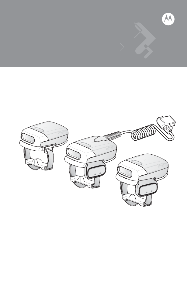
RS507 Hands-Free Imager
Quick Reference Guide
Page 2

2 RS507 Hands-Free Imager
© 2009 MOTOROLA, INC. All rights reserved.
Motorola reserves the right to make changes to any product to improve reliability,
function, or design.
Motorola does not assume any product liability arising out of, or in connection
with, the application or use of any product, circuit, or application described herein.
No license is granted, either expressly or by implication, estoppel, or otherwise
under any patent right or patent, covering or relating to any combination, system,
apparatus, machine, material, method, or process in which Motorola products
might be used. An implied license exists only for equipment, circuits, and
subsystems contained in Motorola products.
MOTOROLA and the Stylized M Logo are registered trademarks of Motorola, Inc.
Other product names mentioned in this manual may be trademarks or registered
trademarks of their respective companies and are hereby acknowledged.
Motorola, Inc.
One Motorola Plaza
Holtsville, N.Y. 11742-1300
www.motorola.com/enterprisemobility.
Warranty
For the complete Motorola hardware product warranty statement, go to:
www.motorola.com/enterprisemobility/warranty.
Patents
This product is covered by one or more patents. For patent information go to:
www.motorola.com/enterprisemobility/patents.
Page 3

Quick Reference Guide 3
Introduction
The RS507 Hands-Free Imager (also referred to as Imager) is wearable barcode
scan solution for both 1D and 2D barcode symbologies. The Imager is also
compatible with a wide range of mobile computers communicating over Bluetooth.
The Imager is designed for a wide range of applications from management of
products in a warehouse, processing deliveries at a courier facility, hospitality to
scanning lift tickets at a ski resort.
The Imager uses camera-based scanning technology, designed to offer flexible
hands-free operation with ergonomic comfort for right or left hand users.
The Imager can be operated in both manual and auto-triggering modes.
Auto-triggering is a patented Intelligent Sensing Technology combining motion
and proximity sensing for triggering the Imager.
The Imager durability is built to last and rated for indoor and outdoor daily use in
intensive scan environments. Built on magnesium chassis, the Imager offers
durability associated with the most rugged mobile computers.
About this Guide
This guide provides basic information on the following topics:
• Cordless Configuration Features on page 5
• Change Trigger Position on page 7
• Getting Started - Cordless Configuration on page 8
• Getting Started - Corded Configuration on page 9
• Establish Bluetooth Connection on page 11
• Scan on page 13
• Status Indications on page 11
• Troubleshooting on page 16
• Resetting the Imager on page 17
• Field Replaceable Parts on page 18
• Cleaning on page 21
• Ergonomic Recommendations on page 24
• Regulatory Information on page 23
• Waste Electrical and Electronic Equipment (WEEE) on page 34
For more information, refer to the RS507 Hands-Free Imager Product Reference
Guide, p/n 72-120802-01 available at:
www.motorola.com/enterprisemobility/manuals
.
Page 4
4 RS507 Hands-Free Imager
Unpacking the Imager
After opening the shipping box, inspect the contents. You should have received
the following:
Model
RS507-IM200000STWR
RS507-IM200000SNWR Triggerless RS507
RS507-IM200000ENWE Triggerless RS507
RS507-IM200000CTWR
Description RS507
Triggered RS507
with standard
battery
with standard
battery
with extended
battery
Corded and
Triggered RS507
Standard
Inspect the equipment for damage. If you are missing any equipment or if you find
any damaged equipment, contact Motorola Enterprise Mobility Support
immediately. See Service Information on backcover for contact information.
Battery
Extended
Battery
Corded
Adapter
Quick Start
Guide
Page 5
Quick Reference Guide 5
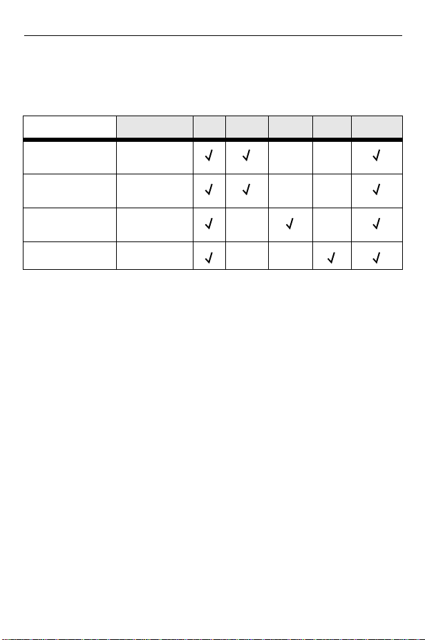
Cordless Configuration Features
NOTE When the imager is provided as triggerless configuration, the
auto-triggering mode is enabled by default.
Battery Release Latch
Imager Window
Battery
Comfort Pad
Trigger Assembly
Fingers Strap
Asset Control Label
Left Scan LED
Beeper
Right Scan LED
Scan Trigger
Restore Key
Strap Buckle
Str ap
Page 6
6 RS507 Hands-Free Imager
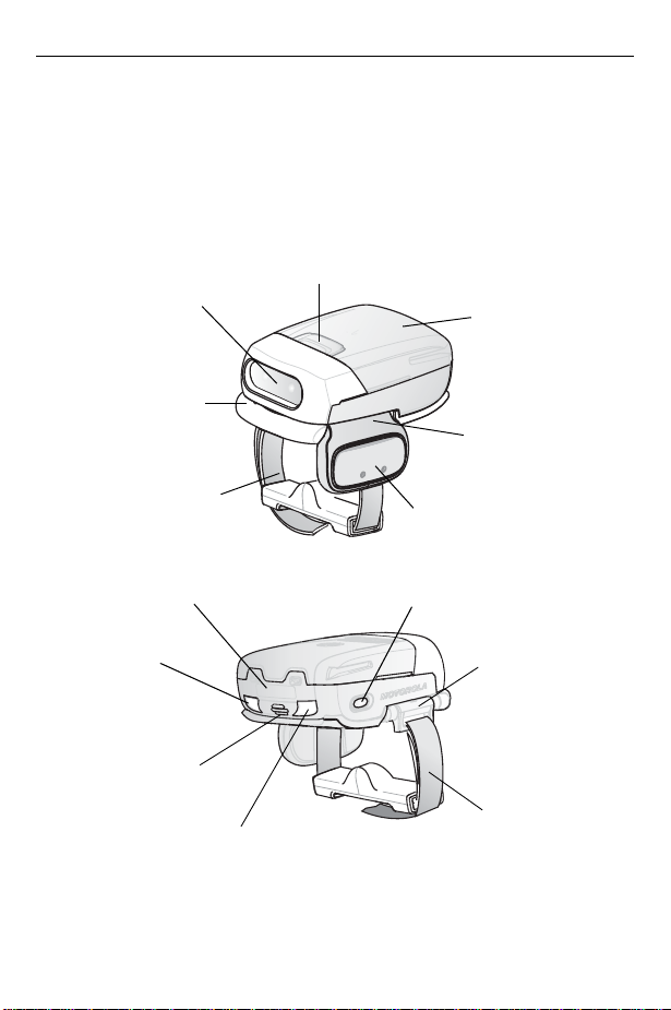
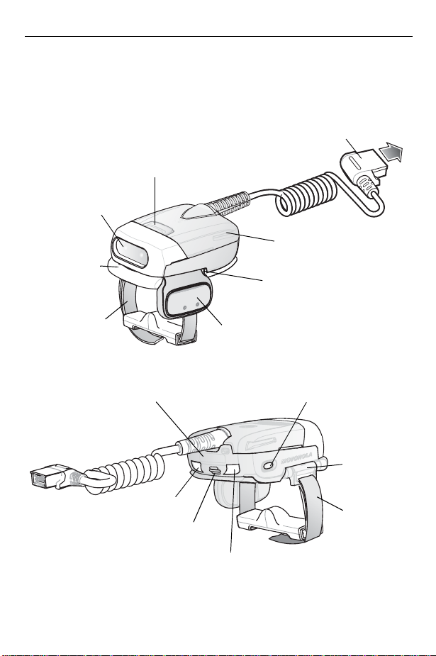
Corded Configuration Features
Interface Cable Connector to WT4090
Release Latch
Imager Window
Corded Adapter
Comfort Pad
Trigger Assembly
Fingers Strap
Asset Control Label
Left Scan LED
Scan Trigger
Restore Key
Strap Buckle
Str ap
Beeper
Right Scan LED
Page 7
Quick Reference Guide 7
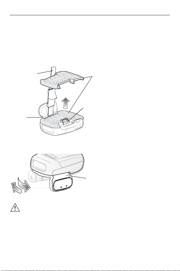
Change Trigger Position
The Trigger Assembly of the Imager rotates to provide left-hand or right-hand use.
1. Remove the Fingers Strap from the Strap Buckle.
2. From bottom of Imager, Hold and pull the Comfort Pad out of the Barcode
Imager.
Fingers Strap
Trigger
Assembly
3. Determine whether the Imager is used on the right or left hand and rotate the
Comfort Pad
Strap Buckle
Trigger Assembly.
Trigger Assembly
CAUTION The Trigger Assembly only rotates 180° around the back of the
scan assembly. Do not rotate the Trigger Assembly past the
designed stops
4. Rotate the Trigger Assembly so that the Scan Trigger is positioned next to the
thumb when the Imager is placed on the index and middle fingers.
5. Position the Comfort Pad onto the Imager.
6. Press the Comfort Pad onto the Imager. When properly installed, the Comfort
Pad “locks” into place.
7. Insert the Fingers Strap into the Strap Buckle
Page 8
8 RS507 Hands-Free Imager
Getting Started - Cordless Configuration
Before using the Imager, charge the battery. The 8-Bay Battery Charger supports both standard and extended capacity batteries.
Charge the Battery
To charge the Imager battery, refer to SAC5070 Quick Start Guide.
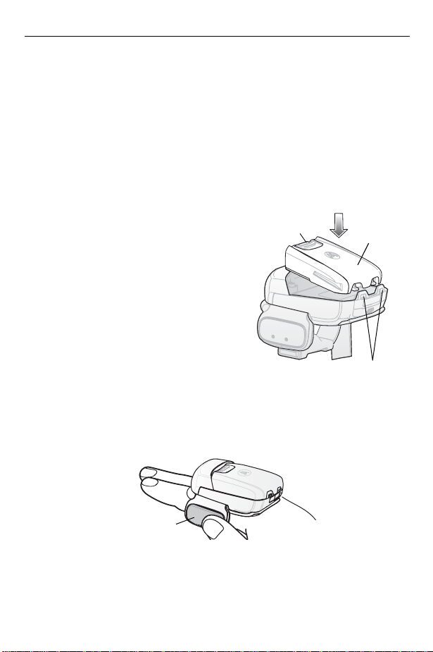
Install the Battery
1. Align the Battery on top of the Imager.
2. Push the battery all the way into the
Locking Slots of the Imager.
3. Firmly press the Battery into the Imager
until a “click” is heard ensuring the
Battery Release Latch is fully engaged
with the Imager.
Remove the Battery
1. Hold the Imager in one hand.
2. Press the Battery Release Latch.
3. Pull up the Battery to release from the Locking Slots of the Imager.
Wear the Imager
1. Slide the Imager onto the index and middle fingers with the Scan Trigger next
to the thumb.
Battery Release
Latch
Battery
Locking Slots
Scan Trigger
Page 9
Quick Reference Guide 9
aaaaaaaaaaaaaaaa
aaaaaaaaaaaaaaaa
aaaaaaaaaaaaaaaa
aaaaaaaaaaaaaaaa
aaaaaaaaaaaaaaaa
aaaaaaaaaaaaaaaa
aaaaaaaaaaaaaaaa
aaaaaaaaaaaaaaaa
aaaaaaaaaaaaaaaa
aaaaaaaaaaaaaaaa
aaaaaaaaaaaaaaaa
aaaaaaaaaaaaaaaa
aaaaaaaaaaaaaaaa
aaaaaaaaaaaaaaaa
aaaaaaaaaaaaaaaa
aaaaaaaaaaaaaaaa
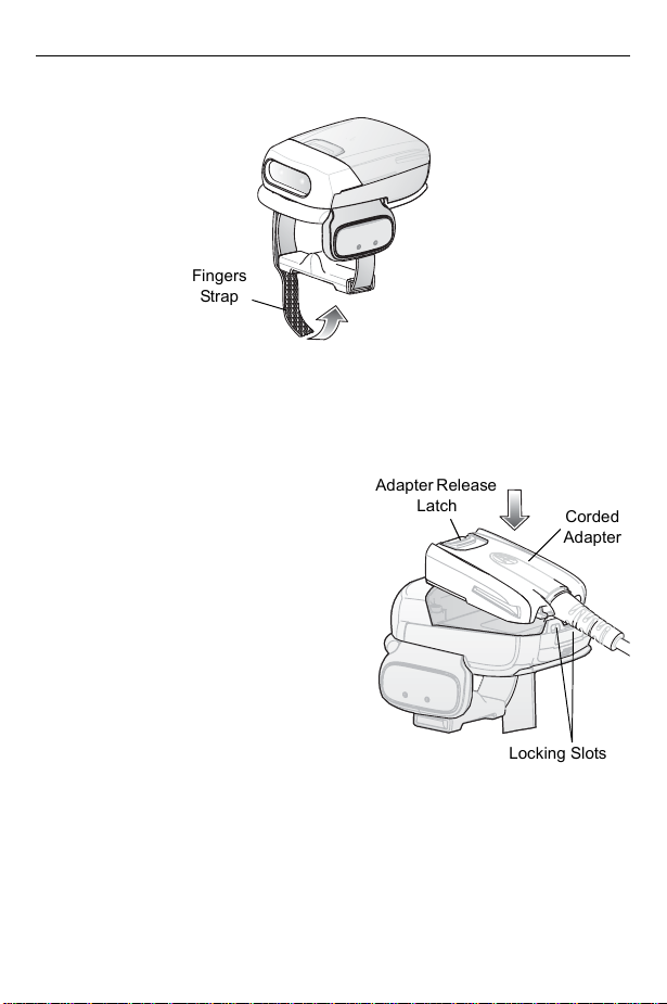
2. Tighten the Fingers Strap.
Fingers
Strap
Getting Started - Corded Configuration
In order to start using the Imager you must install the Corded Adapter.
Connect Corded Adapter
1. Align the Corded Adapter on top of the
Imager.
2. Push the Corded Adapter all the way
into the Locking Slots of the Imager.
3. Firmly press the Corded Adapter into the
Imager until a “click” is heard ensuring
the Adapter Release Latch is fully
engaged with the Imager.
Adapter Release
Latch
Corded
Adapter
Remove the Corded Adapter
1. Hold the Imager in one hand.
2. Press the Adapter Release Latch.
3. Pull up the Corded Adapter to release
from the Locking Slots of the Imager.
Locking Slots
Page 10
10 RS507 Hands-Free Imager
aaaaaaaaaaaaaaaaaa
aaaaaaaaaaaaaaaaaa
aaaaaaaaaaaaaaaaaa
aaaaaaaaaaaaaaaaaa
aaaaaaaaaaaaaaaaaa
aaaaaaaaaaaaaaaaaa
aaaaaaaaaaaaaaaaaa
aaaaaaaaaaaaaaaaaa
aaaaaaaaaaaaaaaaaa
aaaaaaaaaaaaaaaaaa
aaaaaaaaaaaaaaaaaa
aaaaaaaaaaaaaaaaaa
aaaaaaaaaaaaaaaaaa
aaaaaaaaaaaaaaaaaa
aaaaaaaaaaaaaaaaaa
aaaaaaaaaaaaaaaaaa
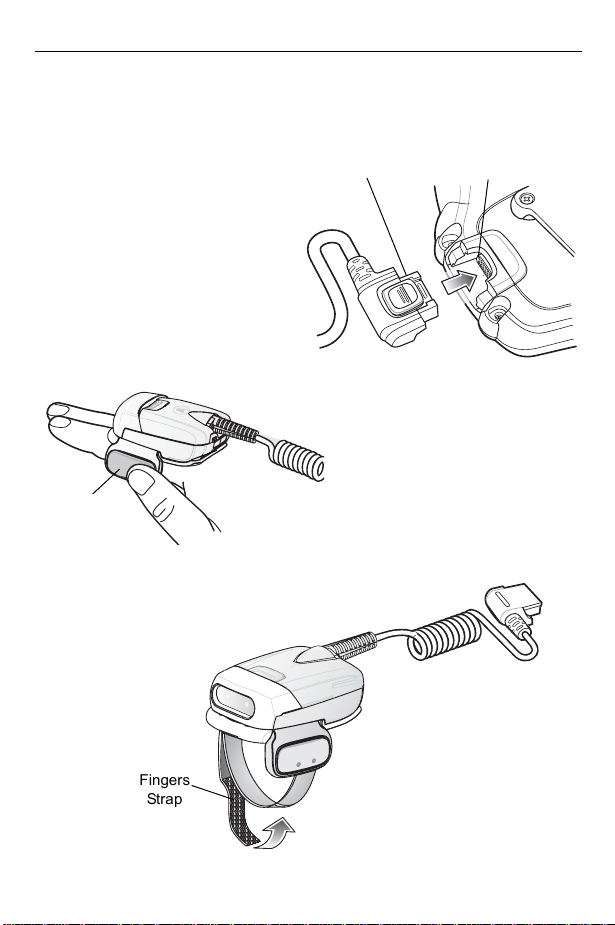
Connect to a Wearable Terminal
The Imager connects to the
WT4090 and mounts on the fingers.
1. On the WT4090, remove the
connector cover.
2. Connect the Imager Interface
Cable Connector to the WT4090
Interface Connector.
Interface Cable
Connector
WT4090 Interface
Connector
Wear the Imager
1. Slide the Imager onto the index
and middle fingers with the Scan
Trigger next to the thumb.
2. Tighten the Fingers Strap.
Fingers
Stra p
4t×Q
Page 11

Quick Reference Guide 11
Status Indications
The Imager has two Scan LEDs that provide identical indications. The Imager is
also equipped with a beeper that generates sound indications in variable tones.
NOTE In corded adapter configuration, beep indications are emitted only from the
WT4090.
No. LED Beep Indication Description
1. None High/low Bluetooth communication is
2. Short green
flashes
3. None Low/high Imager is connected over
4. None High/low Bluetooth communication is
5. None high/low/high/low Properly decoded scan of
6. None Long low/
7. None Long low/
8. One green
flash
9. None 4 long beeps No Bluetooth communication after
None Attempting to connect over
long high/
long high/
Long low/
long high/
High Proper scanning indication
disconnected
Bluetooth
Bluetooth
disconnected - Imager is out of
range
Bluetooth pairing Barcode
Bluetooth connection attempt
failed
Bluetooth connection attempt is
rejected
scanning time-out
Bluetooth Connection
Establish Bluetooth Connection
To establish Bluetooth connection with a mobile computer:
1. Ensure that the Imager is within a range of 10 meters (30 feet) from the mobile
computer.
2. Install the battery on the Imager.
Page 12

12 RS507 Hands-Free Imager
3. Launch the Bluetooth Device (BD) Address application on the mobile
computer. Most BD Address applications display a pairing barcode image on
the screen of the mobile computer.
4. Scan a pairing barcode form the mobile computer screen or any provided label.
When scanning, the Imager emits one string of high/low/high/low beeps.
5. The Scan LED starts flashing green indicating that the Imager is attempting to
establish connection with a mobile computer.
6. When connection is established, the Scan LED turns Off and the Imager emits
one string of low/high beeps. The Imager is connected and ready for scanning.
NOTE When replacing the Imager battery, the Imager memory retains the pairing
information of last paired mobile computer (e.g WT4090).
Remove Bluetooth Connection
1. Scan an unpairing barcode label with the Bluetooth address for disconnecting
the Imager from the mobile computer (e.g WT4090).
2. The Imager emits one string of high/low beeps indicating that Bluetooth
communication with the mobile computer is disconnected.
Restore Lost Bluetooth Connection
The Imager maintains Bluetooth communication with a mobile computer within a
range of 10 meters (30 feet). When the Imager fails to establish connection or
connection is lost during operation, the Imager emits one string of low/high beeps.
To reestablish Bluetooth connection with a mobile computer (e.g WT4090):
1. Ensure that the Imager is within a range of 10 meters (30 feet) from the mobile
computer.
2. Ensure that the mobile computer is On and “awake” (not in Suspend mode).
3. The Imager automatically attempts reconnecting to the mobile computer for 30
seconds (Scan LED flashes green). If automatic re-connection fails, verify that
the Imager is within Bluetooth range and briefly press the Restore Key on the
Imager to reconnect.
4. The Scan LED starts flashing green indicating that the Imager is attempting to
establish connection with a mobile computer (e.g WT4090).
5. The Scan LED turns Off and the Imager emits one string of low/high beeps
indicating that the Imager is connected and ready for scanning.
Page 13

Quick Reference Guide 13
Scan
The Imager uses digital camera technology to take a picture of a barcode and
software decoding algorithms are executed to extract the barcode data from the
image.
Scan Triggering Modes
Manual Triggering (Triggered models only)
1. Launch a scanning software application on the mobile computer or WT4090.
2. Press the Scan Trigger and position the aiming cross hair laser to cover the
barcode. The Imager takes a digital picture (image) of the barcode and stores it
in memory for decoding.
3. One green flash and a high beep sounds to indicate that the barcode was
properly decoded.
NOTE In some configurations proper decoding of a barcode is indicated by
software application running on mobile computer or WT4090.
Auto-triggering (Triggered models only)
The Imager is provided with auto-triggering capability.
In auto-triggering mode, both motion and proximity sensors are used to trigger the
Imager when the user intends to scan a barcode.
With auto-triggering activated, the Imager automatically scans when motion stops
and a barcode is placed within the depth of field of the Imager. The Imager scans
the barcode and turns off to conserve power.
To scan barcode in auto-triggering mode:
1. Bring the Imager within 9 inches ± 1 inch (22.86 cm ± 2.54 cm) of a barcode
label.
2. Hold the Imager steady, aiming at the barcode label.
3. The Imager takes a picture (image) of the barcode and stores it in memory for
decoding.
4. One green flash of the Scan LED and a high beep indicates that a barcode was
properly decoded.
NOTE In some configurations, proper decoding of a barcode is indicated by a
software application running on mobile computer or WT4090.
Page 14

14 RS507 Hands-Free Imager
Aiming the Imager
The aimer of the Imager is a cross hair laser with bright center dot (shown below).
The virtual rectangle made by the Cross Hair Lines reflects the field of view of the
Imager. The aimer is used to position the barcode or object within the field of view.
Cross Hair Lines of
Imager Aimer
1. Enter the symbol in any orientation within the virtual rectangle made by the
cross hair lines.
Linear Barcode
Symbol
@
4
3
2
1
@
Aimer Pattern
The imager can also read a barcode presented within the aiming pattern but
not centered, such as the figure below on the left. The figure on the right,
however, may not be decoded.
@1234@
Right
The aiming pattern is smaller when the Imager is closer to the symbol and
larger when it is farther from the symbol. Scan symbols with smaller bars or
elements (mil size) closer to the unit and those with larger bars or elements
(mil size) farther from the unit.
2. Hold the Imager between two and eleven inches (depending on symbol
density) from the symbol, centering the aiming pattern cross hairs on the
symbol.
3. Press the Scan Button. The aimer pattern illuminates red indicating that the
Laser is on. One green flash of the Scan LED and a high beep indicates that a
barcode was properly decoded.
Virtual rectangle made by the
Cross Hair Lines
PDF417 Symbol
@1234@
Wrong
Page 15

Quick Reference Guide 15
Customize the Imager Behavior
The Imager behavior can be configured by scanning custom barcode tables. The
following table provides examples of configurable Imager features.
Feature Description Default Setting
Beep on
reconnection
attempt
Motion
sensing
Proximity
sensing
Proximity
distance
Low battery
indication
Bluetooth
auto connect
When this parameter is enabled, the
Imager emits a low/high beep when
Bluetooth link is reconnected.
When this parameter is enabled, the
Imager automatically scans when motion
stops in front of the Imager and a barcode
is placed within the depth of field of the
Imager.
When this parameter is enabled, the
Imager automatically scans when sensing
proximity to an object and a barcode is
placed within the depth of field of the
Imager.
When using proximity sensing, you can set
proximity distance to Short, Mid or Long.
When this parameter is enabled, the
Imager flashes red every 15 seconds when
battery power is low.
The Imager automatically tries to reconnect
to a remote device when a disconnection
occurs that is due to the radio losing
communication. This can happen if the
Imager goes out of the mobile computer
range.
The following auto connect options are
available: “None”, “On power up”, “Back in
Bluetooth range”, “On power up & back in
Bluetooth range”.
The beep on
reconnection
attempt feature is
disabled by default.
Motion sensing is
set by default to on
for triggerless
models and off for
triggered models.
Proximity sensing is
set by default to on
for trigger less
models and off for
triggered models.
Proximity distance
is set to Long by
default.
Low battery
indication is
disabled by default.
Bluetooth auto
connect is set to
“Back in Bluetooth
range” by default.
Page 16

16 RS507 Hands-Free Imager
Troubleshooting
Problem Cause Solution
Laser aimer does
not display when
pressing the Scan
Trigger
Imager does not
decode a barcode
Corded:
Interface
cable is not secure
Cordless:
not charged
Power is not applied
to Imager
Scan application on
the mobile computer
(e.g WT4090) is not
functioning
Imager software
does not respond
Barcode is
unreadable
Exit window is dirty Clean exit window with a lens tissue.
Barcode symbology
is not supported or
enabled
Cordless:
link is disconnected
Battery is
Bluetooth
Verify that the interface cable is
properly connected
Replace or charge battery
Corded: Verify that the mobile
computer (e.g WT4090) has a
charged battery installed
Cordless: Replace or Charge Imager
battery
Restart the scanning application on
the mobile computer (e.g WT4090)
Reset the Imager (See Resetting the
Imager on page 17)
Verify that the barcode is not
defective, i.e., smudged or broken
Tissues for eyeglasses work well. Do
not use tissues coated with lotion
See your system administrator
Reestablish Bluetooth connection
(See Establish Bluetooth Connection
on page 11)
Page 17

Quick Reference Guide 17
Resetting the Imager
If the Imager stops responding to input, reset it. There are two reset functions,
warm boot and cold boot. Perform a warm boot first. If the Imager still does not
respond, perform a cold boot.
Warm Boot
To perform warm boot, press and hold the Restore Key for more than six seconds.
Cold Boot
Cold boot restores the Imager’s operation by resetting it’s software. To perform
cold boot, remove and re-insert the battery into the Imager. When using a corded
RS507 model with WT4090, remove and reconnect the interface cable that
connects between the Imager and the WT4090.
Page 18

18 RS507 Hands-Free Imager
Field Replaceable Parts
Part Description
1 CLMPT-RS507-R
2 KT-BKL-RS507-R
3 CLMPN-RS507-R
4 KT-PAD-RS507-R
5 KT-STRPN-RS507-R
6 KT-S TRPT-RS507-R
7 BTRY-RS50EAB00-01 Standard Battery
8 BTRY-RS50EAB02-01 Extended Battery
9 ADPTRWT -RS507-R Corded Adapter
Trigger Assembly
Set of 10 Strap Buckles
Triggerless Fingers Clamp
Set of 10 Comfort Pads
Set of 10 Triggerless Fingers Strap with Fingers
Support
Set of 10 Trigger Fingers Strap with Fingers
Support
7
1
a
5
2
3
8
4
6
Fingers
Support
9
Page 19

Quick Reference Guide 19
Comfort Pad Replacement
Removal
Hold and pull Comfort Pad out of the Barcode Imager.
Installation
1. Position the Comfort Pad onto the Imager as
shown.
2. Press the Comfort Pad onto the Imager. When
properly installed, the Comfort Pad “locks” into
place.
Trigger Assembly Replacement
Removal
1. Turn the Imager upside-down.
2. Remove the Comfort Pad.
3. Rotate the Trigger Assembly to
align with the back of the Imager.
4. Use a paper clip or similar object to
press the Release Latch.
5. Lift the Trigger Assembly off the
scan assembly.
1
Release Latch
3
Imager Back
2
Installation
1. Turn the Imager upside-down.
2. Position the Trigger Assembly to
align with the back of the Imager.
3. Lower the Trigger Assembly to
the scan assembly.
4. Rotate Trigger Assembly 1/4 turn
counterclockwise.
5. Press the Comfort Pad onto the
Imager. When properly installed,
the Comfort Pad “locks” into
place.
2
Triggerless
Finger Clamp
1
Page 20

20 RS507 Hands-Free Imager
y
Note: An optional Triggerless Finger Clamp should be installed when the
Imager is intended to be used in Motion and Proximity Initiated Barcode Read
mode.
Fingers Strap Replacement (Trigger Assembly)
Removal
1. Remove the Fingers Strap from the
Strap Buckle.
2. Pull the Fingers Strap out of the
Trigger Assembly.
Installation
1. Align a new Finger Strap with the
Slots in the Trigger Assembly.
2. Gently press the Strap Pins to
engage with the Slots of the Trigger
Assembly. The Strap Pins snap into
the Slots.
3. Slip the Fingers Strap through the
Strap Buckle.
Slots
Fingers Strap
Strap Pins
Trigger Assembl
Strap Buckle
Page 21

Quick Reference Guide 21
Fingers Strap Replacement (Triggerless Finger Clamp)
Removal
1. Remove the Fingers Strap from the
Strap Buckles.
Installation
1. Slip the Fingers Strap through the
Strap Buckles.
Strap Buckles
Strap Buckle Replacement
Strap
Buckle
Removal
Press the Strap Buckle out of the
Trigger Assembly Pin.
Installation
1. Align the pin slots of Strap Buckle
with the pin of the Trigger Assembly.
2. Gently press the pin slots of Strap Buckle to engage with the pin of the Trigger
Assembly. The pin slots snaps into the pin.
Trigger Assembly Pin
Cleaning
Wipe the exit window periodically with a lens tissue or other material suitable for
cleaning eyeglasses.
CAUTION Do not pour, spray, or spill any liquid on the Imager.
Page 22

22 RS507 Hands-Free Imager
The gold plated battery contacts do not tarnish or oxidize. No maintenance should
be needed. If the contacts need to be cleaned:
1. Wet the tip of a cotton swab with isopropyl alcohol and squeeze the excess
alcohol from the swab.
2. Wipe the metal contacts with the damp swab.
Page 23

Quick Reference Guide 23
Regulatory Information
This device is approved under the Enterprise Mobility business of Motorola, Inc.
("Motorola").
This guide applies to Model Number RS507.
All Motorola devices are designed to be compliant with rules and regulations in
locations they are sold and will be labeled as required.
Local language translations are available at the following website:
www.motorola.com/enterprisemobility/support
CAUTION Any changes or modifications to Motorola equipment, not
expressly approved by Motorola, could void the user's authority
to operate the equipment.
Only use Motorola approved and UL Listed accessories, battery
packs and battery chargers.
Do NOT attempt to charge damp/wet mobile computers or
batteries. All components must be dry before connecting to an
external power source.
Bluetooth® Wireless Technology
This is an approved Bluetooth® product. For more information or to view End
Product Listing, please visit http://www.bluetooth.org/tpg/listings,cfm
Wireless Device Country Approvals
Regulatory markings, subject to certification, are applied to the device signifying
the radio(s) is/are approved for use in the following countries: United States,
Canada, Japan, China, S. Korea, Australia, and Europe (see note below).
Please refer to the Motorola Declaration of Conformity (DoC) for details of other
country markings. This is available at http://www2.symbol.com/doc/
Note: For 2.4GHz Products: Europe includes, Austria, Belgium, Bulgaria, Czech
Republic, Cyprus, Denmark, Estonia, Finland, France, Germany, Greece,
Hungary, Iceland, Ireland, Italy, Latvia, Liechtenstein, Lithuania, Luxembourg,
Malta, Netherlands, Norway, Poland, Portugal, Romania, Slovak Republic,
Slovenia, Spain, Sweden, Switzerland and the United Kingdom.
..
.
Page 24

24 RS507 Hands-Free Imager
Health and Safety Recommendations
Ergonomic Recommendations
CAUTION In order to avoid or minimize the potential risk of ergonomic injury
follow the recommendations below. Consult with your local Health &
Safety Manager to ensure that you are adhering to your company’s
safety programs to prevent employee injury.
• Reduce or eliminate repetitive motion
• Maintain a natural position
• Reduce or eliminate excessive force
• Keep objects that are used frequently within easy reach
• Perform tasks at correct heights
• Reduce or eliminate vibration
• Reduce or eliminate direct pressure
• Provide adjustable workstations
• Provide adequate clearance
• Provide a suitable working environment
• Improve work procedures.
Warnings for Use of Wireless Devices
Please observe all warning notices with regard to the usage of wireless devices.
Potentially Hazardous Atmospheres - Vehicles Use
You are reminded of the need to observe restrictions on the use of radio devices
in fuel depots, chemical plants etc. and areas where the air contains chemicals or
particles (such as grain, dust, or metal powders) and any other area where you
would normally be advised to turn off your vehicle engine.
Safety in Hospitals
Wireless devices transmit radio frequency energy and may affect medical
electrical equipment.
Page 25

Quick Reference Guide 25
Wireless devices should be switched off wherever you are requested to do so in
hospitals, clinics or healthcare facilities. These requests are designed to prevent
possible interference with sensitive medical equipment.
Pacemakers
Pacemaker manufacturers recommended that a minimum of 15cm (6 inches) be
maintained between a handheld wireless device and a pacemaker to avoid
potential interference with the pacemaker. These recommendations are
consistent with independent research and recommendations by Wireless
Technology Research.
Persons with Pacemakers:
• Should ALWAYS keep the device more than 15cm (6 inches) from their
pacemaker when turned ON.
• Should not carry the device in a breast pocket.
• Should use the ear furthest from the pacemaker to minimize the potential for
interference.
• If you have any reason to suspect that interference is taking place, turn OFF
your device.
Other Medical Devices
Please consult your physician or the manufacturer of the medical device, to
determine if the operation of your wireless product may interfere with the medical
device.
RF Exposure Guidelines
Safety Information
Reducing RF Exposure - Use Properly
Only operate the device in accordance with the instructions supplied.
International
The device complies with internationally recognized standards covering human
exposure to electromagnetic fields from radio devices. For information on
"International" human exposure to electromagnetic fields refer to the Motorola
Declaration of Conformity (DoC) at http://www2.symbol.com/doc/
.
Page 26

26 RS507 Hands-Free Imager
EU
Handheld Devices
This device was tested for typical body-worn operation. Use only Motorola tested
and approved belt-clips, holsters, and similar accessories to ensure EU
Compliance.
US and Canada
Handheld Devices
This device was tested for typical body-worn operation. Use only Motorola tested
and approved belt-clips, holsters, and similar accessories to ensure FCC
Compliance. The use of third-party belt-clips, holsters, and similar accessories
may not comply with FCC RF exposure compliance requirements, and should be
avoided.
Laser Devices
Complies with 21CFR1040.10 and 1040.11 except for deviations pursuant to
Laser Notice No. 50, dated July 26, 2001, and with
EN60825-1:1994+A1:2002+A2:2001 and IEC60825-1:1993+A1:1997+A2:2001.
The laser classification is marked on one of the labels on the device.
Class 1 Laser devices are not considered to be hazardous when used for their
intended purpose. The following statement is required to comply with US and
international regulations:
Caution: Use of controls, adjustments or performance of procedures other than
those specified herein may result in hazardous laser light exposure.
Class 2 laser Imagers use a low power, visible light diode. As with any very bright
light source, such as the sun, the user should avoid staring directly into the light
beam. Momentary exposure to a Class 2 laser is not known to be harmful.
LASER LIGHT
DO NOT STARE INTO BEAM
CLASS 2 LASER PRODUCT
LASERSTRAHLUNG
NICHT IN DEN STRAHL BLICKEN
LASER KLASSE 2
LUMIÈRE LASER
NE PAS REGARDER DANS LE
FAISCEAU
APPAREIL À LASER DE CLASSE 2
Page 27

Quick Reference Guide 27
p
Imager Labeling
Country Stam
(example)
Batteries
Taiwan - Recycling
EPA (Environmental Protection Administration) requires dry
battery producing or importing firms in accordance with Article
15 of the Waste Disposal Act are required to indicate the
recycling marks on the batteries used in sales, giveaway or
promotion. Contact a qualified Taiwanese recycler for proper battery disposal.
Battery Information
Motorola rechargeable battery packs are designed and constructed to the highest
standards within the industry.
However, there are limitations to how long a battery can operate or be stored
before needing replacement. Many factors affect the actual life cycle of a battery
pack, such as heat, cold, harsh environmental conditions and severe drops.
Page 28

28 RS507 Hands-Free Imager
When batteries are stored over six (6) months, some irreversible deterioration in
overall battery quality may occur. Store batteries at half of full charge in a dry, cool
place, removed from the equipment to prevent loss of capacity, rusting of metallic
parts and electrolyte leakage. When storing batteries for one year or longer, the
charge level should be verified at least once a year and charged to half of full
charge.
Replace the battery when a significant loss of run time is detected.
Standard warranty period for all Motorola batteries is 3 months, regardless if the
battery was purchased separately or included as part of the mobile computer or
bar code scanner. For more information on Motorola batteries, please visit:
http:/mysymbolcare.symbol.com/battery/batbasics1.html
Battery Safety Guidelines
• The area in which the units are charged should be clear of debris and
combustible materials or chemicals. Particular care should be taken where the
device is charged in a non commercial environment.
• Follow battery usage, storage, and charging guidelines found in the user's
guide.
• Improper battery use may result in a fire, explosion, or other hazard.
• To charge the mobile device battery, the battery and charger temperatures
must be between +32 ºF and +104 ºF (0 ºC and +40 ºC)
• Do not use incompatible batteries and chargers. Use of an incompatible
battery or charger may present a risk of fire, explosion, leakage, or other
hazard. If you have any questions about the compatibility of a battery or a
charger, contact Motorola Enterprise Mobility support.
• Do not disassemble or open, crush, bend or deform, puncture, or shred.
• Severe impact from dropping any battery-operated device on a hard surface
could cause the battery to overheat.
• Do not short circuit a battery or allow metallic or conductive objects to contact
the battery terminals.
• Do not modify or remanufacture, attempt to insert foreign objects into the
battery, immerse or expose to water or other liquids, or expose to fire,
explosion, or other hazard.
• Do not leave or store the equipment in or near areas that might get very hot,
such as in a parked vehicle or near a radiator or other heat source. Do not
place battery into a microwave oven or dryer.
• Battery usage by children should be supervised.
Page 29

Quick Reference Guide 29
• Please follow local regulations to promptly dispose of used re-chargeable
batteries.
• Do not dispose of batteries in fire.
• Seek medical advice immediately if a battery has been swallowed.
• In the event of a battery leak, do not allow the liquid to come in contact with the
skin or eyes. If contact has been made, wash the affected area with large
amounts of water and seek medical advice.
• If you suspect damage to your equipment or battery, contact Motorola
Enterprise Mobility support to arrange for inspection.
In accordance with Clause 5, IEC 825 and EN60825, the following information is
provided to the user:
Page 30

30 RS507 Hands-Free Imager
Radio Frequency Interference Requirements-FCC
Note: This equipment has been tested and found to comply with
the limits for a Class B digital device, pursuant to Part 15 of the
protection against harmful interference in a residential installation. This equipment
generates, uses and can radiate radio frequency energy and, if not installed and
used in accordance with the instructions, may cause harmful interference to radio
communications. However there is no guarantee that interference will not occur in
a particular installation. If this equipment does cause harmful interference to radio
or television reception, which can be determined by turning the equipment off and
on, the user is encouraged to try to correct the interference by one or more of the
following measures:
• Reorient or relocate the receiving antenna
• Increase the separation between the equipment and receiver
• Connect the equipment into an outlet on a circuit different from that to which
the receiver is connected
• Consult the dealer or an experienced radio/TV technician for help.
Radio Transmitters (Part 15) - USA
This device complies with Part 15 of the FCC Rules. Operation is subject to the
following two conditions: (1) this device may not cause harmful interference, and
(2) this device must accept any interference received, including interference that
may cause undesired operation.
Radio Frequency Interference Requirements - Canada
This Class B digital apparatus complies with Canadian ICES-003.
Cet appareil numérique de la classe B est conforme à la norme NMB-003 du
Canada.
Radio Transmitters - Canada
This device complies with RSS 210 of Industry & Science Canada. Operation is
subject to the following two conditions: (1) this device may not cause harmful
interference and (2) this device must accept any interference received, including
interference that may cause undesired operation.
Label Marking: The Term “IC:” before the radio certification only signifies that
Industry Canada technical specifications were met.
FCC rules. These limits are designed to provide reasonable
Page 31

Quick Reference Guide 31
Marking and European Economic Area (EEA)
following restrictions:
• Maximum radiated transmit power of 100mW EIRP in the frequency range
• France, outside usage is restricted to 10mW EIRP
• Italy requires a user license for outside usage.
Statement of Compliance for Wireless Devices
Motorola hereby, declares that this device is in compliance with the essential
requirements and other relevant provisions of Directive 1999/5/EC. A Declaration
of Conformity may be obtained from http://www2.symbol.com/doc/
Japan (VCCI) - Voluntary Control Council for Interference
Class B ITE
This is a Class B product based on the standard of the Voluntary Control Council
for Interference from Information Technology Equipment (VCCI). If this is used
Bluetooth® Wireless Technology for use through the EEA has the
2.400 -2.4835 GHz
.
Page 32

32 RS507 Hands-Free Imager
near a radio or television receiver in a domestic environment, it may cause radio
interference. Install and use the equipment according to the instruction manual.
Korea Warning Statement for Class B ITE
Other Countries
Declarações Regulamentares para RS507 - Brazil
Note: The certification mark applied to the RS507 is for Restrict Radiation
Equipment. This equipment operates on a secondary basis and does not have the
right for protection against harmful interference from other users including same
equipment types. Also this equipment must not cause interference to systems
operating on primary basis.
For more information consult the website www.anatel.gov.br
Nota: "A marca de certificação se aplica ao Transceptor, modelo RS507. Este
equipamento opera em caráter secundário, isto é, não tem direito a proteção
contra interferência prejudicial, mesmo de estações do mesmo tipo, e não pode
causar interferência a sistemas operando em caráter primário."
Para maiores informações sobre ANATEL consulte o site: www.anatel.gov.br
Mexico
Restrict Frequency Range to: 2.450 - 2.4835 GHz.
Sri Lanka- Restrict Frequency Range to: 2.400 - 2.430 GHz.
Tai wan - 臺灣
According to Administrative Regulations on Low Power Radio Waves Radiated
Devices:
Article 12
Without permission granted by the DGT, any company, enterprise, or user is not
allowed to change frequency, enhance transmitting power or alter original
.
.
Page 33

Quick Reference Guide 33
characteristic as well as performance to an approved low power radio-frequency
devices.
Article 14
The low power radio-frequency devices shall not influence aircraft security and
interfere legal communications; If found, the user shall cease operating
immediately until no interference is achieved.
The said legal communications means radio communications is operated in
compliance with the Telecommunications Act.
The low power radio-frequency devices must be susceptible with the interference
from legal communications or ISM radio wave radiated devices.
低功率電波輻射性電機管理辦法
第十二條
經型式認證合格之低功率射頻電機,非經許可,公司、商號或使用者均不得擅自變
更頻率、加大功率或變更原設計之特性及功能。
第十四條
低功率射頻電機之使用不得影響飛航安全及干擾合法通信;經發現有干擾現象時,
應立即停用,並改善至無干擾時方得繼續使用。
前項合法通信,指依電信規定作業之無線電通信。
低功率射頻電機須忍受合法通信或工業、科學及醫療用電波輻射性電機設備之干
擾。
限制頻率範圍是: 2.400 - 2.4835 GHz。 最大發射功率 : 27dBm
5.250 - 5.350 GHz。
5.725 - 5.850 GHz。
2.4GHz: 11 個通道
50 GHz
Korea
Page 34

34 RS507 Hands-Free Imager
Waste Electrical and Electronic Equipment (WEEE)
English: For EU Customers: All products at the end of their life must be returned
to Motorola for recycling. For information on how to return product, please go to:
www.motorola.com/recycling/weee
Bulgarish: За клиенти от ЕС: След края на полезния им живот всички
продукти трябва да се връщат на Motorola за рециклиране. За информация
относно връщането на продукти, моля отидете на адрес:
www.motorola.com/recycling/weee
Dansk: Til kunder i EU: Alle produkter skal returneres til Motorola til recirkulering,
når de er udtjent. Læs oplysningerne om returnering af produkter på:
www.motorola.com/recycling/weee
Deutsch: Für Kunden innerhalb der EU: Alle Produkte müssen am Ende ihrer
Lebensdauer zum Recycling an Motorola zurückgesandt werden. Informationen
zur Rücksendung von Produkten finden Sie unter
www.motorola.com/recycling/weee
Eesti: EL klientidele: kõik tooted tuleb nende eluea lõppedes tagastada
taaskasutamise eesmärgil Motorola'ile. Lisainformatsiooni saamiseks toote
tagastamise kohta külastage palun aadressi: www.motorola.com/recycling/weee
Español: Para clientes en la Unión Europea: todos los productos deberán
entregarse a Motorola al final de su ciclo de vida para que sean reciclados. Si
desea más información sobre cómo devolver un producto, visite:
www.motorola.com/recycling/weee
.
.
.
.
.
.
Français: Clients de l'Union Européenne : Tous les produits en fin de cycle de vie
doivent être retournés à Motorola pour recyclage. Pour de plus amples
informations sur le retour de produits, consultez :
www.motorola.com/recycling/weee
Italiano: per i clienti dell'UE: tutti i prodotti che sono giunti al termine del rispettivo
ciclo di vita devono essere restituiti a Motorola al fine di consentirne il riciclaggio.
Per informazioni sulle modalità di restituzione, visitare il seguente sito Web:
www.motorola.com/recycling/weee
.
.
Page 35

Quick Reference Guide 35
Magyar: Az EU-ban vásárlóknak: Minden tönkrement terméket a Motorola
vállalathoz kell eljuttatni újrahasznosítás céljából. A termék visszajuttatásának
módjával kapcsolatos tudnivalókért látogasson el a
www.motorola.com/recycling/weee
Nederlands: Voor klanten in de EU: alle producten dienen aan het einde van hun
levensduur naar Motorola te worden teruggezonden voor recycling. Raadpleeg
www.motorola.com/recycling/weee
van producten.
Português: Para clientes da UE: todos os produtos no fim de vida devem ser
devolvidos à Motorola para reciclagem. Para obter informações sobre como
devolver o produto, visite:
Românesc: Pentru clienţii din UE: Toate produsele, la sfârşitul duratei lor de
funcţionare, trebuie returnate la Motorola pentru reciclare. Pentru informaţii
despre returnarea produsului, accesaţi:
Slovenski: Za kupce v EU: vsi izdelki se morajo po poteku življenjske dobe vrniti
podjetju Motorola za reciklažo. Za informacije o vraèilu izdelka obišèite:
www.motorola.com/recycling/weee
weboldalra.
voor meer informatie over het terugzenden
www.motorola.com/recycling/weee.
www.motorola.com/recycling/weee.
.
Suomi: Asiakkaat Euroopan unionin alueella: Kaikki tuotteet on palautettava
kierrätettäväksi Motorola-yhtiöön, kun tuotetta ei enää käytetä. Lisätietoja tuotteen
palauttamisesta on osoitteessa
Svenska: För kunder inom EU: Alla produkter som uppnått sin livslängd måste
returneras till Motorola för återvinning. Information om hur du returnerar produkten
finns på www.motorola.com/recycling/weee
www.motorola.com/recycling/weee.
.
Page 36

Service Information
If you have a problem using the equipment, contact your facility’s Technical or
Systems Support. If there is a problem with the equipment, they will contact the
Motorola Enterprise Mobility Support at:
www.motorola.com/enterprisemobility/support
For the latest version of this guide go to:
www.motorola.com/enterprisemobility/manuals
Motorola, Inc.
One Motorola Pl aza
Holtsville, New York 11742, USA
1-800-927-9626
http://www.motorola.com
MOTOROLA and the Stylized M Logo and Symbol and the Symbol logo are registered in the U.S.
Patent and Trademark Office. All other product or service names are the property of their
registered owners. © Motorola, Inc. 2009
.
.
@72-115988-01@
72-115988-01 Revision A - January 2009
 Loading...