

Page 1

5
RFID Guidelines
This chapter provides an overview of how RFID works and the ZPL commands used to create
RFID labels.
Contents
Overview . . . . . . . . . . . . . . . . . . . . . . . . . . . . . . . . . . . . . . . . . . . . . . . . . . . . . . . . . . . . . 62
Transponder Placement. . . . . . . . . . . . . . . . . . . . . . . . . . . . . . . . . . . . . . . . . . . . . . . . . . 62
ZPL II Commands for RFID . . . . . . . . . . . . . . . . . . . . . . . . . . . . . . . . . . . . . . . . . . . . . . . 63
Sample of RFID Programming . . . . . . . . . . . . . . . . . . . . . . . . . . . . . . . . . . . . . . . . . . . . . 70
23063L-001 Rev. 1 6/7/2004 RXiIIIPlus User Guide 61
Page 2

RFID Guidelines
Overview
Overview
The R110XiIIIplus “smart” label printer-encoders serve as dynamic tools for both printing and
encoding RFID labels, tickets, and tags. The printer encodes information on ultra-thin UHF
RFID transponders embedded in “smart” labels. It then immediately verifies proper encoding
and prints bar codes, graphics, and/or text on the label’s surface. For more information about
RFID media, see RFID “Smart” Labels on page 16.
Function of an encoded “smart” label depends on factors such as where the label is placed on
an item as well as on the contents of the item (such as metals or liquids). Contact the supplier
of your RFID transponders for assistance with these types of issues.
Transponder Placement
Communication between the “smart” label and the printer is established when the transponder
lines up with the printer’s antenna. The optimal transponder position varies with the
transponder size, its configuration, and the type of RFID IC chip used.
Print quality may be affected by printing directly over the transponder. In particular, there is an
area on each label immediately around the location of the IC chip where the printer may print
with low quality. Design your printed label around the location of the chip in the type of
approved “smart” label that you select. For the list of approved transponders and related
placement specifications, go to http://www.rfid.zebra.com/r110.htm.
Important • It is important to use transponders that have been specifically approved for use in
this RFID printer. Failure to do so may result in the inability to read or write to the embedded
RFID tags. As new transponders become commercially available, Zebra will evaluate them for
compatibility with this printer. For the list of approved transponders, go to
http://www.rfid.zebra.com/r110.htm.
62 RXiIIIPlus User Guide 6/7/2004 23063L-001 Rev. 1
Page 3

ZPL II Commands for RFID
Printing and encoding (writing) of “smart” labels is handled through the use of Zebra
Programming Language (ZPL). Each transponder has memory that can be read from through
ZPL commands, and most transponders have memory that can be written to. The printer
divides the ZPL commands that it receives into two categories: RFID and non-RFID (such as
the printing commands for bar codes or human-readable text). The RFID commands are
executed first.
ZPL commands also provide for exception handling, such as setting the number of read/write
retries before declaring a transponder defective. For example, if an RFID transponder fails to
program correctly or cannot be detected, the printer ejects it and prints the word “VOID”
across the label. This process continues for the number of RFID tags specified by the
command using the same data and format.
The following pages provide the ZPL II commands that can be used for RFID applications.
Important • If a parameter is designated as not applicable, any value entered for the parameter
will be ignored, but the place holder for the field is required.
RFID Guidelines
ZPL II Commands for RFID
^RS
23063L-001 Rev. 1 6/7/2004 RXiIIIPlus User Guide 63
Page 4

RFID Guidelines
^HV
^HV
Host Verification
Description This command is used to return data from specified fields, along with an
optional ASCII header, to the host. It can be used with any field that has been assigned a
number with the
^RT command.
Format
The following table identifies the parameters for this format.
Parameters Details
# = field number
specified with another
command
n = number of bytes to be
returned
h = header Header (in uppercase ASCII characters) to be returned with the data.
^HV#,n,h
The value assigned to this parameter should be the same as the one used in the
^RT command.
Accepted values: 0 to 9999
Default value: 0
Accepted values: 1 to 256
Default value: 64
Acceptable values: 0 to 3072 characters
Default value: none
64 RXiIIIPlus User Guide 6/7/2004 23063L-001 Rev. 1
Page 5

^RS
RFID Setup
RFID Guidelines
^RS
Important • Use care when using this command in combination with ^RT (reading tag data).
Problems can occur if the data read from the tag is going to be printed on the label. Any data
read from the transponder must be positioned to be printed above the read/write position.
Failure to do this will prevent read data from being printed on the label.
Description The ^RS command moves the RFID tag into the effective area for reading or
writing or for possible error handling if there is an error.
Format
The following table identifies the parameters for this format.
Parameters Details
^RSt,p,v,n,e
t =tag type Accepted values:
• 1 = Auto detect (automatically determine the tag type by querying the tag)
Default value: 1
p = read/write position of
the transponder in the
vertical (Y axis) in
dot rows from the top
of the label
v = length of void
printout in vertical (Y
axis) dot rows
n = number of labels to
try in case of
read/encode failure
Set to 0 (no movement) if the transponder is already in the effective area
without moving the media.
Accepted values: 0 to label length
Default value: label length minus 8 dot rows
Default value: label length
Accepted values: 0 to label length
Default value: 3
Accepted values: 1 to 10 (number of labels)
e = error handling If an error persists after the specified number of labels are tried, perform this
error handling action.
Accepted values:
• N = No action (printer drops the label format causing the error and moves to
the next queued label)
• P = Place printer in Pause mode (label format stays in the queue until the user
cancels)
• E = Place printer in Error mode (label format stays in the queue until the user
cancels)
Default value: N
Note • You can set the printer to send an error message to the host as an
unsolicited message for each failure. To enable or disable the unsolicited error
message, refer to the
RFID error in these commands is
^SX and ^SQ ZPL commands. The parameter for the
V.
23063L-001 Rev. 1 6/7/2004 RXiIIIPlus User Guide 65
Page 6
RFID Guidelines
^RS
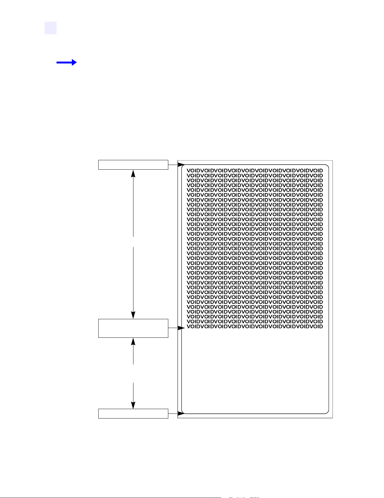
Example 1 • This example sets the printer to move the media to 800 dots from the top of the
media [or label length minus 800 from the bottom (leading edge) of the media] and voids the
rest of the media in case of an error. The printer will try to print two labels, then will pause the
printer if printing and encoding fail.
^XA
^RS,800,,2,P^FS
^XZ
The following illustration shows the resulting voided label. Note where the void starts. The
media has been moved 800 dot rows from the top of the label (label length minus 800 dot rows
from the bottom (leading edge) of a label) to bring the transponder into the effective area to
read/write a tag. If the printer fails the operation, the rest of the media is voided.
Top of label
800 dot rows
Start of RFID
operation
Label length minus
800 dot rows
Bottom of label
66 RXiIIIPlus User Guide 6/7/2004 23063L-001 Rev. 1
Page 7
RFID Guidelines
^RS
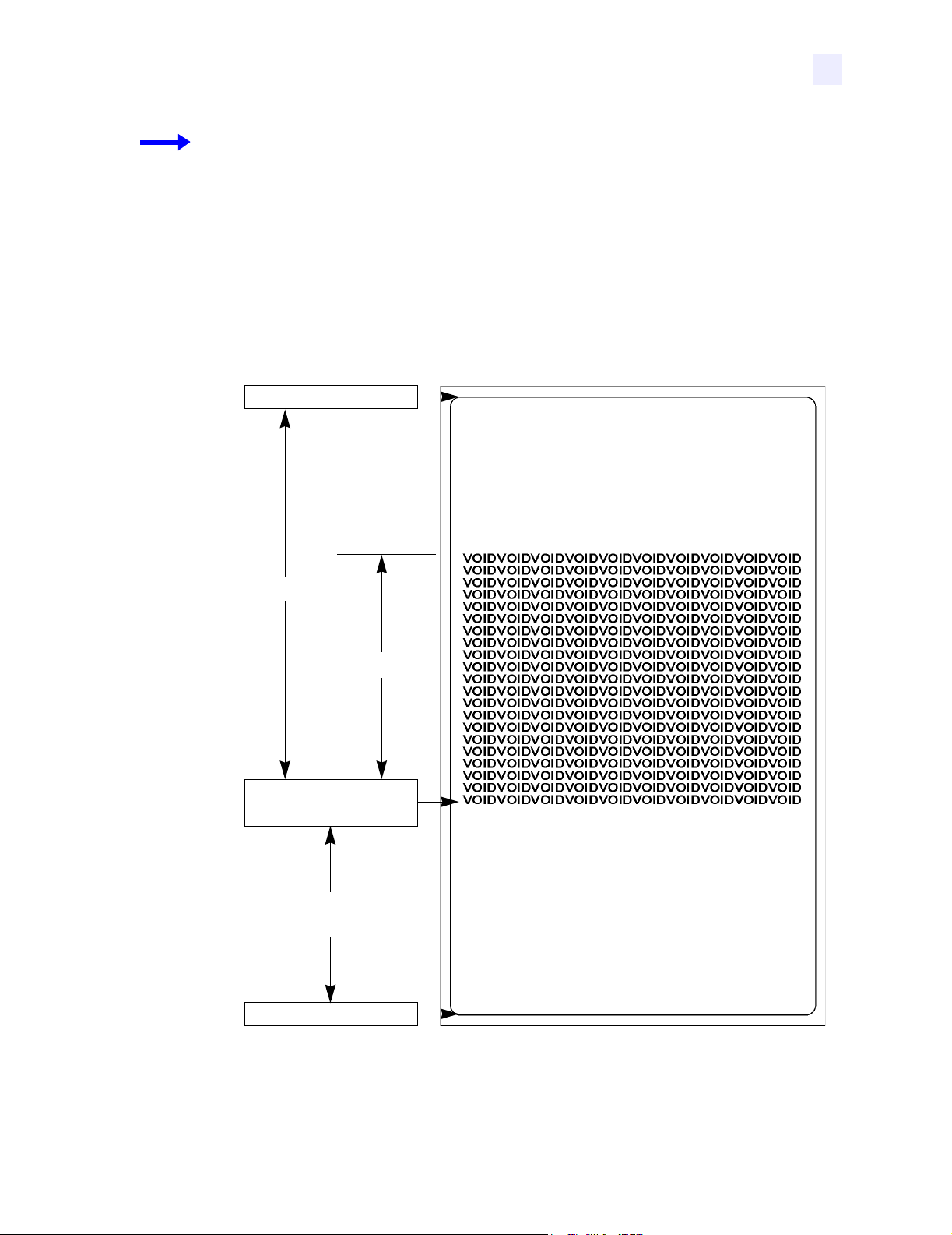
Example 2 • This example sets the printer to move the media to 800 dots from the top of the
media [or label length - 500 from the bottom (leading edge) of the media] and prints “void”
500 dots in vertical length (Y axis) in case of an error.
^XA
^RS,800,500,2,P^FS
^XZ
The following illustration shows the resulting voided label. Note where the void starts. The
media has been moved 800 dot rows from the top of the label [label length minus 800 dot rows
from the bottom (leading edge) of a label] to bring the transponder into the effective area to
read/write a tag. If the printer fails the operation, an area that is 500 dot rows of the media is
voided instead of the entire rest of the media.
Top of label
800 dot rows
500 dot rows
Start of RFID
operation
Label length minus
800 dot rows
Bottom of label
23063L-001 Rev. 1 6/7/2004 RXiIIIPlus User Guide 67
Page 8

RFID Guidelines
^RT
^RT
Read Tag
Description The ^RT command tells the printer to read the current RFID tag data. The data
can be sent back to the host via the
^HV command.
Format
The following table identifies the parameters for this format.
Parameters Details
# = number to be
assigned to the field
b = starting block
number*
n = number of blocks
to read*
^RT#,b,n,f,r,m,s
Accepted values: 0 to 9999
Default value: 0
Accepted values: 0 to n, where n is the maximum number of blocks for the tag.
Default value: 0
Accepted values: 1 to n, where n is the maximum number of blocks minus the
starting block number. For example, if the tag has 8 blocks (starting with
block 0) and you start with block 6, n can be 2. This would give you block 6 and
block 7 information.
Default value: 1
f =format Accepted values:
•0 (ASCII)
• 1 (Hexadecimal)
Default value: 0
r = number of retries Accepted values: 0 to 10
Default value: 0
m =motion Accepted values:
• 0 (Feed label after writing.)
• 1 (No Feed after writing. Other ZPL may cause a feed.)
Default value: 0
s = special mode For EPC Class 1 (Alien reader) only. Not applicable for EPC class 0.
Default value: 0 (Do not read if mismatched checksum.)
Accepted values: 1 (Read even if mismatched checksum.)
*Not applicable for R110XiIIIplus
Example • This sample reads a tag, prints the data on a label, and sends the string
Tag Data:xxxxxxxx back to the host. The data read will go into the ^FN1 location of the
format. The printer will retry the command five times, if necessary.
^XA
^FO20,120^A0N,60^FN1^FS
^RT1,,,,5^FS
^HV1,,Tag Data:^FS
^XZ
68 RXiIIIPlus User Guide 6/7/2004 23063L-001 Rev. 1
Page 9

^WT
Write Tag
RFID Guidelines
^WT
Note • Check the amount of data memory available for the tag that you will be using. If more is
sent than the memory can hold, the data will be truncated.
Description The ^WT command allows you to program the current RFID tag.
Format
The following table identifies the parameters for this format.
Parameters Details
^WTb,r,m,w,f,v
b =block number Accepted values:
• 0 (ID data/EPC)
• 1 (User data)
Default value: 0
r = number of
retries
Accepted values: 0 to 10
Default value: 0
m =motion Accepted values:
• 0 (Feed label after writing.)
• 1 (No Feed after writing. Other ZPL may cause a feed.)
Default value: 0
w = write protect Accepted values:
• 0 (Not write protected.)
• 1 (Write protect.)
Default value: 0
f = data format Accepted values:
• 0 (ASCII)
• 1 (Hexadecimal)
Default value: 0
v = verify valid
data*
*Not applicable for R110XiIIIplus
Default value: y
Accepted values:
• n (Do not verify)
• y (Verify valid data [Hex A5A5 in the first two bytes] before writing)
Example • This sample encodes data “RFIDRFID” and will try writing up to five times, if
necessary.
^XA
^WT,5^FDRFIDRFID^FS
^XZ
23063L-001 Rev. 1 6/7/2004 RXiIIIPlus User Guide 69
Page 10

RFID Guidelines
Sample of RFID Programming
Sample of RFID Programming
ZPL II is Zebra’s label design language. ZPL II lets you create a wide variety of labels from
the simple to the very complex, including text, bar codes, and graphics.
This section is not intended as an introduction to ZPL II. If you are a new ZPL II user, order
the ZPL II Programming Guide (part number 46530L) or go to
download the guide.
For your programming, do the following:
1. Set up the printer and turn the power On (I).
http://support.zebra.com to
2. Use any word processor or text editor capable of creating ASCII-only files (for example,
use Microsoft
®
Word and save as a .txt file) and type in the label format exactly as shown
in the sample label format shown in Table 7.
3. Save the file in a directory for future use. Use the “.zpl” extension.
4. Copy the file to the printer.
From the DOS command window, use the “COPY” command to send a file to the Zebra
printer. For example, if your file name is format1.zpl then type,
COPY FORMAT 1.ZPL XXXX
where XXXX is the port to which your Zebra printer is connected (such as LPT1).
5. Compare your results with those shown. If your printout does not look like the one shown,
confirm that the file you created is identical to the format shown, then repeat the printing
procedure. If nothing prints, refer to
• Printer Setup on page 7
• Printer Operation on page 21
• Front Panel Controls on page 41
• Troubleshooting on page 99
to make sure that your system is set up correctly.
70 RXiIIIPlus User Guide 6/7/2004 23063L-001 Rev. 1
Page 11

RFID Guidelines
Sample of RFID Programming
Table 7 • Sample ZPL Code and Results
Line Number Type This Label Format Resulting Printout
1 ^XA ZEBRA
2^RS,0^FS
5A65627261000000
3 ^WT^FDZebra^FS
4 ^FO100,100^A0n,60^FN0^FS
5 ^FO100,200^A0n,40^FN1^FS
6^RT0^FS
7 ^RT1,,,1^FS
8^XZ
Line 1 Indicates start of label format.
Line 2 Indicates no movement for media.
Line 3 Writes the data “Zebra” to the tag.
Line 4 Print field number ‘0’ at location 100,100.^FN0 is replaced by what we read on line 6.
Line 5 Print field number ‘1’ at location 100,200. ^FN1 is replaced by what we read on line 7.
Line 6 Read Tag into field number 0 in ASCII format (default).
Line 7 Read Tag into field number 1 in hexadecimal format.
Line 8 End of label format.
23063L-001 Rev. 1 6/7/2004 RXiIIIPlus User Guide 71
Page 12

RFID Guidelines
Sample of RFID Programming
Notes • ___________________________________________________________________
__________________________________________________________________________
__________________________________________________________________________
__________________________________________________________________________
__________________________________________________________________________
__________________________________________________________________________
__________________________________________________________________________
__________________________________________________________________________
__________________________________________________________________________
__________________________________________________________________________
__________________________________________________________________________
__________________________________________________________________________
__________________________________________________________________________
__________________________________________________________________________
__________________________________________________________________________
__________________________________________________________________________
__________________________________________________________________________
__________________________________________________________________________
__________________________________________________________________________
To provide feedback on this document, please send your comments to techpubs@zebra.com, or
write your comments on this page and fax to the following:
Fax: 1.847.821.1795 Attention: TechPubs — CTC
72 RXiIIIPlus User Guide 6/7/2004 23063L-001 Rev. 1
Page 13

6
Data Ports
This chapter describes the standard communication ports available to connect the printer to your
computer or network.
Contents
Parallel Port . . . . . . . . . . . . . . . . . . . . . . . . . . . . . . . . . . . . . . . . . . . . . . . . . . . . . . . . . . . 74
Serial Port . . . . . . . . . . . . . . . . . . . . . . . . . . . . . . . . . . . . . . . . . . . . . . . . . . . . . . . . . . . . 76
Serial Pin Configuration . . . . . . . . . . . . . . . . . . . . . . . . . . . . . . . . . . . . . . . . . . . . . . . . 77
RS-232 Interface Connections. . . . . . . . . . . . . . . . . . . . . . . . . . . . . . . . . . . . . . . . . . . 78
RS-422/RS-485 Interconnections . . . . . . . . . . . . . . . . . . . . . . . . . . . . . . . . . . . . . . . . 80
USB 2.0 Port . . . . . . . . . . . . . . . . . . . . . . . . . . . . . . . . . . . . . . . . . . . . . . . . . . . . . . . . . . 81
23063L-001 Rev. 1 6/7/2004 RXiIIIPlus User Guide 73
Page 14
Data Ports
Parallel Port
Parallel Port
When communicating via the parallel port, the values selected must be the same as those used
by the host equipment connected to the printer. Port selection for status information is
determined by the channel sending the request. The parallel port can be set for bidirectional or
unidirectional communication. The default setting is bidirectional.
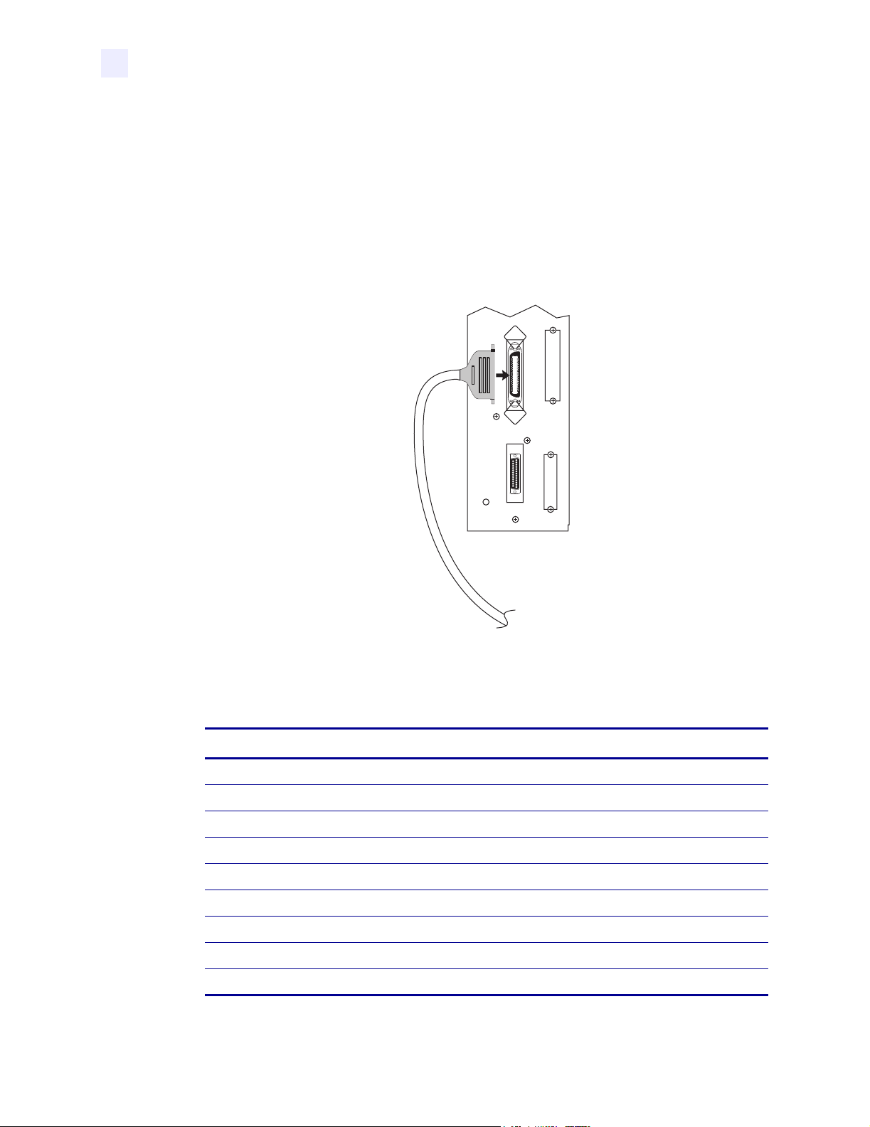
A standard 36-pin parallel connector (Figure 30) is available on the back of the printer for
connection to the data source.
Figure 30 • Parallel Connector
Table 8 shows the pin configuration and function of a standard computer-to-printer parallel
cable.
Table 8 • Parallel Cable Pin Configuration
36-Pin Connectors Description
1 nStrobe/HostClk
2–9 Data Bits 1–8
10 nACK/PtrClk
11 Busy/PtrBusy
12 PError/ACKDataReq
13 Select/Xflag
14 nAutoFd/HostBusy
15 Not used
16, 17 Ground
74 RXiIIIPlus User Guide 6/7/2004 23063L-001 Rev. 1
Page 15

Table 8 • Parallel Cable Pin Configuration (Continued)
36-Pin Connectors Description
18 +5 V at 750 mA
The maximum current draw may be limited by option
configuration.
19–30 Ground
31 ninit
32 nFault/NDataAvail
33, 34 Not used
35 +5 V through a 1.8 KΩ Resistor
36 NSelectin/1284 active
Data Ports
Parallel Port
23063L-001 Rev. 1 6/7/2004 RXiIIIPlus User Guide 75
Page 16
Data Ports
Serial Port
Serial Port
To communicate using the serial data port of the printer, you must choose the number of data
and stop bits, parity, and handshaking. Parity applies only to data transmitted by the printer
because the parity of received data is ignored.
The values selected must be the same as those used by the host equipment connected to the
printer. Default settings are 9600 baud, 8 data bits, 1 stop bit, no parity, and XON/XOFF.
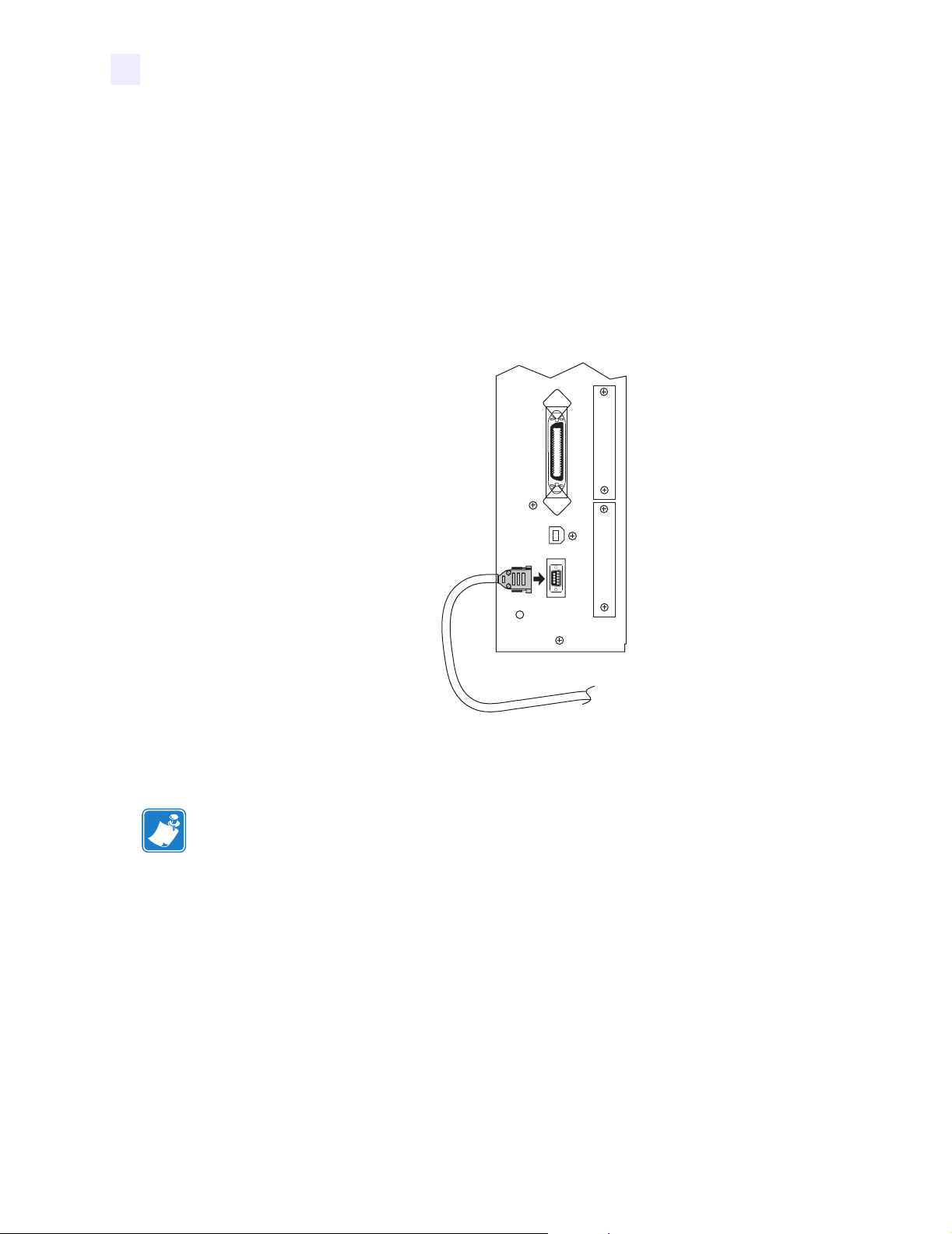
Connect the serial data cable to the female DB-9 connector (Figure 31) on the back panel of
the printer.
Figure 31 • Serial Connector
Use a DB-9 to DB-25 interface module for all RS-232 connections through a DB-25 cable. An
interface module is required for RS-422/RS-485 interface support (see RS-422/RS-485
Interconnections on page 80).
Note • For all RS-232 input and output signals, the printer follows the specifications of the
Electronics Industries Association (EIA) RS-232 and the Consultative Committee for
International Telegraph and Telephone (CCITT) V.24.
76 RXiIIIPlus User Guide 6/7/2004 23063L-001 Rev. 1
Page 17

Serial Pin Configuration
Table 9 shows the pin configuration and function of the rear panel serial data connector on
the printer.
Table 9 • Serial Connector Pin Configuration
Pin No. Name Description
1 — Not connected
2 RXD Receive data—data input to printer
3 TXD Transmit data—data output from printer
4 DTR Data terminal ready—output from printer
5 SG Signal ground
6 DSR Data set ready—input to printer
7 RTS Request to send—output from printer
8 CTS Clear to send—input to printer
Data Ports
Serial Port
\
9 +5 VDC +5 VDC at 750 mA
The maximum current draw may be limited by option
configuration.
23063L-001 Rev. 1 6/7/2004 RXiIIIPlus User Guide 77
Page 18
Data Ports
Serial Port
RS-232 Interface Connections
Note • Adapters are available from Zebra Technologies LLC.
• RS-422/RS-485 adapter, Zebra part number 33114M
• RS-232 DB-9 to DB-25 adapter, Zebra part number 33109M
Direct Connection to a Computer
The printer is configured as Data Terminal Equipment (DTE).
Note • Use a null modem (crossover) cable to connect the printer to a computer or any other
DTE device.
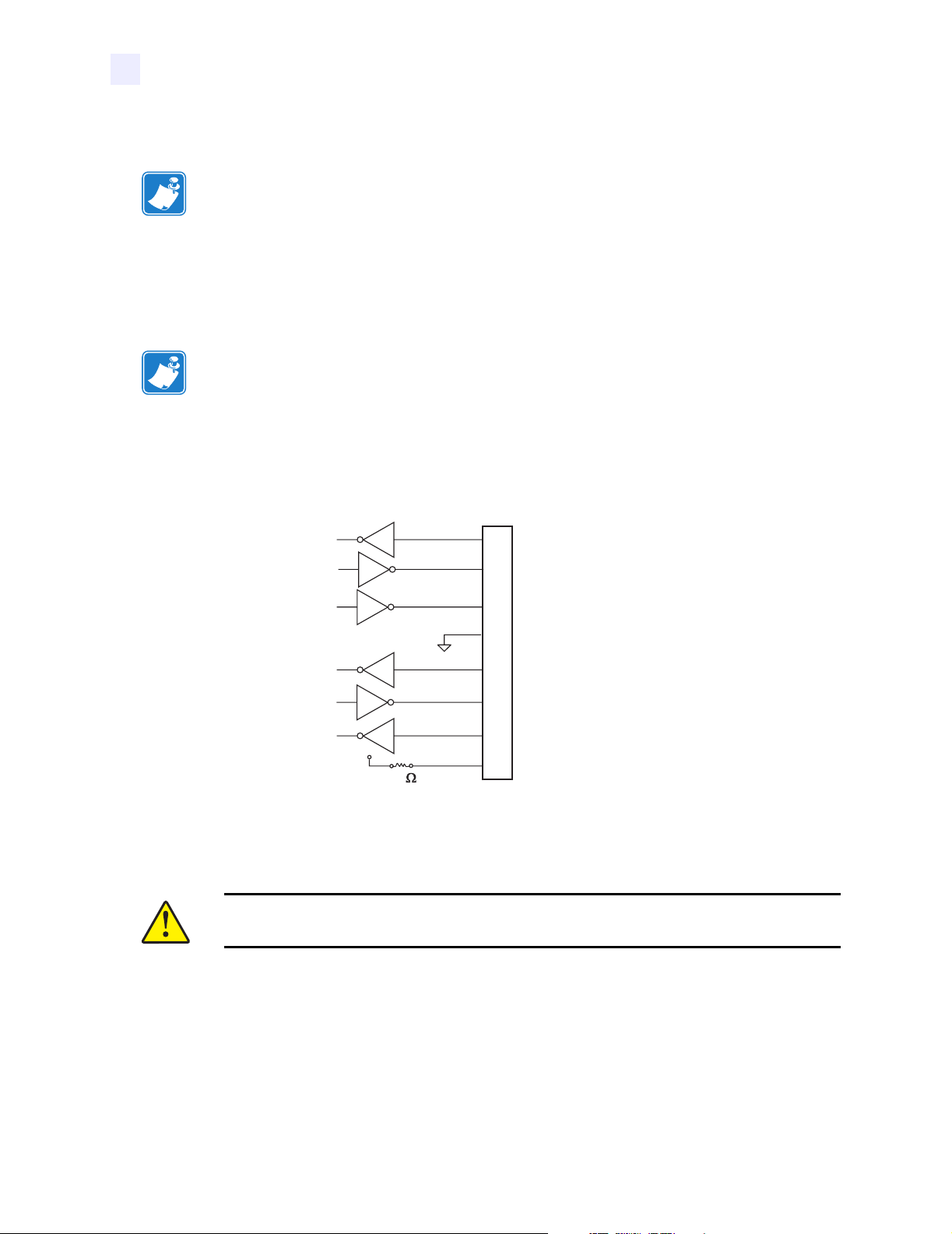
Figure 32 shows the internal connections of the printer’s RS-232 connector.
Figure 32 • RS-232 Connections
RS-232 Connector (DTE)
Rear Panel Female DB-9
2
RXD (receive data) input
3
TXD (transmit data) output
4
DTR (data terminal ready) output
5
SG (signal ground)
6
DSR (data set ready) input
7
RTS (request to send) output
8
+5 VDC
R1
1K
NOTE: Pin 1 is unused and unterminated.
CTS (clear to send) input
9
+5 VDC signal source
Pin 9 is also available as a +5 VDC signal source at 750 mA. The maximum current draw may
be limited by option configuration.
Caution • To enable this capability, a qualified service technician must install a jumper on
the printer’s main logic board on JP1, pins 2 and 3.
78 RXiIIIPlus User Guide 6/7/2004 23063L-001 Rev. 1
Page 19
Data Ports
Serial Port
DB-9 to DB-25 Connections
An interface adapter is required (Zebra part number 33109M) to connect the printer’s DB-9
interface to a DB-25 connector. A generic DB-25 adapter CAN be used, although the +5 VDC
signal source would not be passed through the adapter.
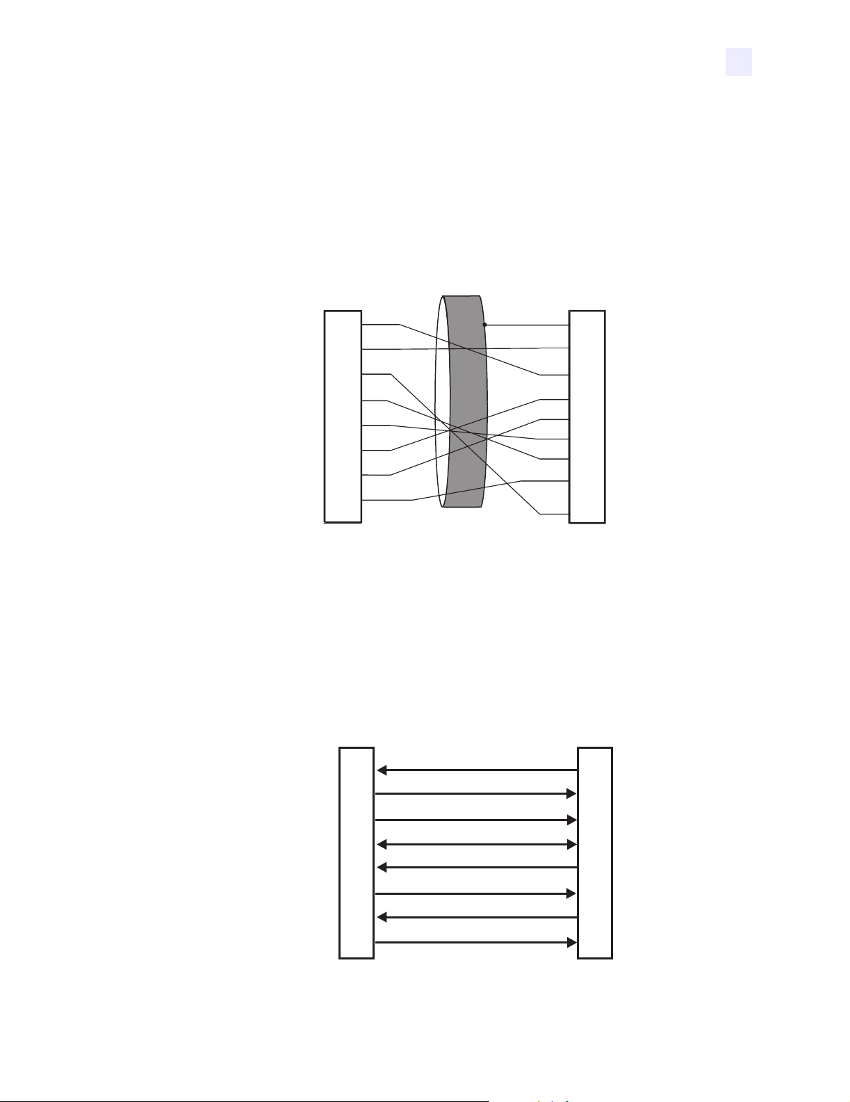
Figure 33 shows the connections required for the DB-9 to DB-25 interface.
Figure 33 • DB-9 to DB-25 Connections
Male DB-9 Adapter
Connector
(plugs into printer)
RXD
2
TXD
3
DTR
4
SG
5
DSR
6
RTS
7
CTS
8
+5 VDC
9
SIGNAL
NOTE: Pin 1 of DB-9 connector is unused and unterminated.
Female DB-25 Adapter
Connector
(plugs into cable)
FG
1
TXD
RXD
RTS
CTS
DSR
+5 VDC
SIGNAL
DTR
SG
2
3
4
5
6
7
9
20
Modem Connection
When the printer is connected via its RS-232 interface to Data Communication Equipment
(DCE) such as a modem, use a standard RS-232 (straight-through) interface cable.
Figure 34 shows the connections required for this cable.
Figure 34 • RS-232 Connections
DTE
(Printer)
2
3
4
5
6
7
8
9
NOTE: Pin 1 is unused and unterminated at the printer.
23063L-001 Rev. 1 6/7/2004 RXiIIIPlus User Guide 79
RXD (receive data)
TXD (transmit data)
DTR (data terminal ready)
SG (signal ground)
DSR (data set ready)
RTS (request to send)
CTS (clear to send)
+5 VDC signal source
DCE
(Modem, etc.)
2
3
4
5
6
7
8
9
Page 20
Data Ports
Serial Port
RS-422/RS-485 Interconnections
Caution • A qualified service technician must install a jumper on the printer’s main logic
board at JP1, pins 2 and 3, for the RS-422/RS-485 interface adapter to function properly.
An interface adapter (Zebra part number 33114M) is required to connect the printer’s RS-232
DB-9 interface to a host computer through an RS-422 or RS-485 interface. A generic DB-25
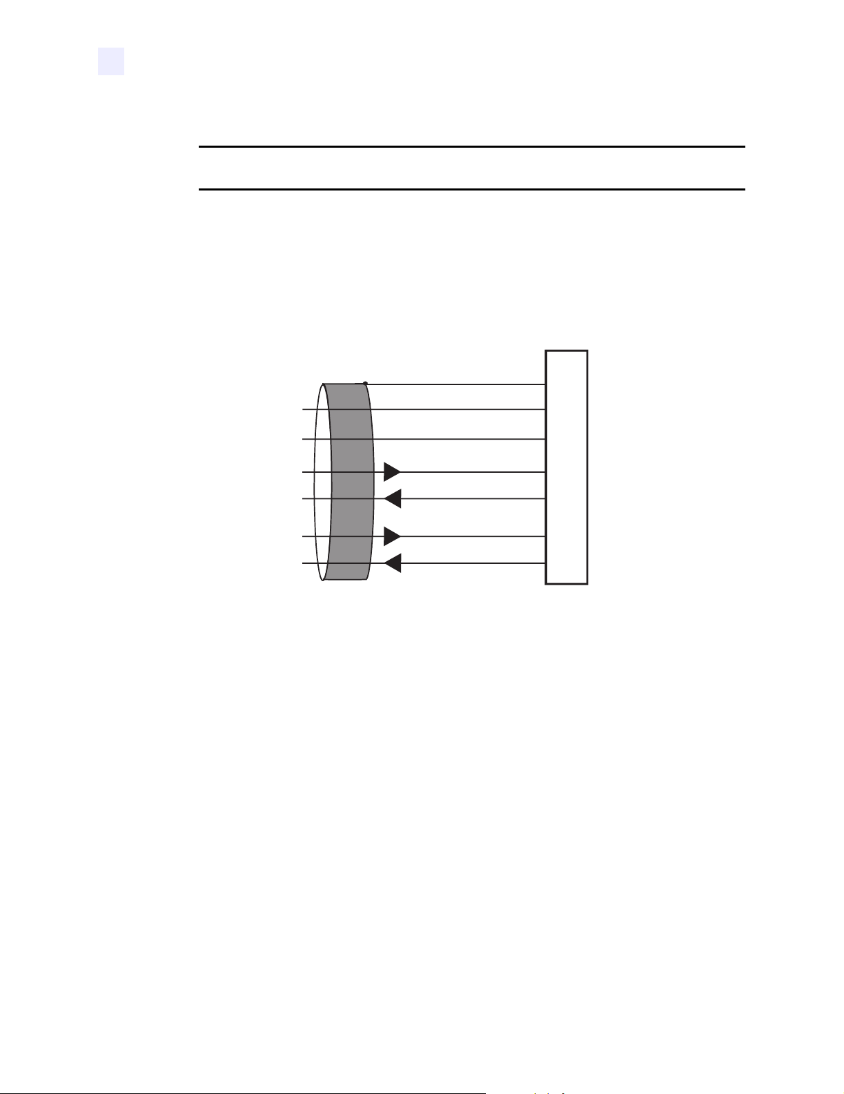
adapter can be used. Figure 35 shows the cable wiring for interconnecting the DB-9 to the
interface adapter’s DB-25 female connector.
Figure 35 • DB-9 to DB-25 Connections
Frame ground
+5 VDC 725 mA source
Signal ground ref.
Data input B (–)
Data output B (–)
Data input A (+)
Data output A (+)
NOTE: Pins 2–8, 10, 12, 15, 17, 18, and 20–25 are unused and unterminated.
Female DB-25 Connector on
RS-422/RS-485 Adapter
1
9
11
13
14
16
19
80 RXiIIIPlus User Guide 6/7/2004 23063L-001 Rev. 1
Page 21
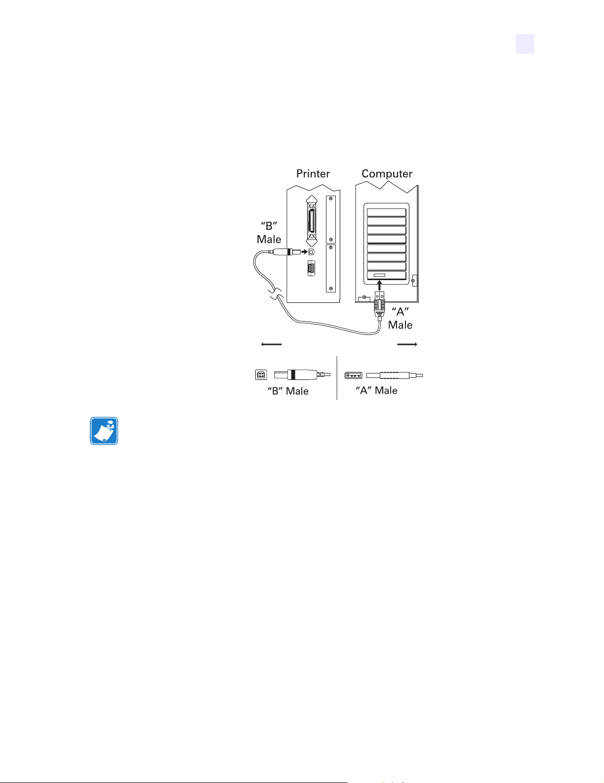
USB 2.0 Port
A USB 2.0 port (which is USB 1.1 and 1.0 compatible) is available to connect your printer to
the host equipment. The industry-standard USB cable has an A-male connector on one end and
a B-male connector on the other end as shown in Figure 36.
Data Ports
USB 2.0 Port
Figure 36 • USB Connectors
=
16.4 ft (5 m) maximum
Note • Use a USB 2.0-certified compliant cable no longer than 16.4 ft (5 m) long. A cable that
meets these requirements is available from Zebra (part number 33011).
23063L-001 Rev. 1 6/7/2004 RXiIIIPlus User Guide 81
Page 22

Data Ports
USB 2.0 Port
Notes • ___________________________________________________________________
__________________________________________________________________________
__________________________________________________________________________
__________________________________________________________________________
__________________________________________________________________________
__________________________________________________________________________
__________________________________________________________________________
__________________________________________________________________________
__________________________________________________________________________
__________________________________________________________________________
__________________________________________________________________________
__________________________________________________________________________
__________________________________________________________________________
__________________________________________________________________________
__________________________________________________________________________
__________________________________________________________________________
__________________________________________________________________________
__________________________________________________________________________
__________________________________________________________________________
To provide feedback on this document, please send your comments to techpubs@zebra.com, or
write your comments on this page and fax to the following:
Fax: 1.847.821.1795 Attention: TechPubs — CTC
82 RXiIIIPlus User Guide 6/7/2004 23063L-001 Rev. 1
Page 23

7
Memory Cards
This chapter describes the optional cards that can be used with the printer and gives instructions for
installation.
Contents
PCMCIA Memory Card . . . . . . . . . . . . . . . . . . . . . . . . . . . . . . . . . . . . . . . . . . . . . . . . . . 84
CompactFlash Card . . . . . . . . . . . . . . . . . . . . . . . . . . . . . . . . . . . . . . . . . . . . . . . . . . . . . 86
23063L-001 Rev. 1 6/7/2004 RXiIIIPlus User Guide 83
Page 24

Memory Cards
PCMCIA Memory Card
PCMCIA Memory Card
A Type 1- or Type II-compliant PCMCIA memory card holds extra memory or font options for
the printer. The card is hot-swappable (it can be installed while the printer is on).
Electrostatic Discharge Caution • Observe proper electrostatic safety precautions when
handling any static-sensitive components such as circuit boards and printheads.
To install the PCMCIA card, complete these steps:
1. Remove the PCMCIA card shield from the rear of the printer (Figure 37).
Figure 37 • PCMCIA Card Installation
1 2 3 4
PCMCIA card shield
1
PCMCIA card
2
Notch
3
Card-eject button
4
2. Insert the PCMCIA card, with the notch up, into the card slot as shown. Insert it far
enough to make the eject button pop out.
84 RXiIIIPlus User Guide 6/7/2004 23063L-001 Rev. 1
Page 25

Memory Cards
PCMCIA Memory Card
3. Reinstall the PCMCIA card shield over the PCMCIA card and card slot.
Note • The PCMCIA card may take a few minutes to initialize. The PAU SE light
flashes while the card initializes. If the card is already initialized, the PAUSE light
flashes only once or twice after the card is installed.
The printer is ready to operate with the additional memory or font option. To be sure that
the card has successfully initialized, print a configuration label as instructed in Print a
Printer Configuration Label on page 31 and review it to see whether the new memory
card information is listed.
23063L-001 Rev. 1 6/7/2004 RXiIIIPlus User Guide 85
Page 26

Memory Cards
CompactFlash Card
CompactFlash Card
A CompactFlash card is a nonvolatile memory card that stores data even when the power to
the printer is turned off. A Type I-compliant CompactFlash card holds extra memory or
optional fonts for your printer.
Caution • This procedure should only be performed by qualified service technicians.
Electrostatic Discharge Caution • Observe proper electrostatic safety precautions when
handling any static-sensitive components such as circuit boards and printheads.
To install a CompactFlash card, complete these steps:
1. Turn the AC power Off (O).
2. Disconnect the AC power cord from the printer.
3. Remove the two screws near the bottom of the electronics cover (Figure 38).
Figure 38 • Printer Exterior
1
3
4
Electronics cover
1
Screws
2
Channel
3
Lip of cover
4
4. Lift the electronics cover at the rear top corner. Pull the corner forward and up, then lift the
2
cover up and away from the printer.
86 RXiIIIPlus User Guide 6/7/2004 23063L-001 Rev. 1
Page 27

Memory Cards
CompactFlash Card
5. Insert the CompactFlash card into the card slot on the upper portion of the option board.
Insert the card with the back (unlabeled) side of the card facing out. The card can be
inserted only one way and should snap into place.
Figure 39 shows where to insert the CompactFlash card.
Figure 39 • Compact Flash Card Insertion
1 2 3
Option board
1
Card slot
2
Compact flash card
3
6. Reinstall the electronics cover by lowering the cover so the lip of the cover goes into the
channel on the top of the printer.
7. Secure the cover by reinstalling the two screws near the bottom of the cover.
8. Reconnect the printer AC power cord.
9. Press and hold CANCEL while turning the printer On (I).
The printer prints a configuration label.
10. Check for the presence of additional memory or optional fonts by looking at the
information on the configuration label.
Note • The CompactFlash card may take a few minutes to initialize. If the process is not
successfully completed within 10 minutes, contact Technical Support at
http://www.zebra.com/SS/service_support.htmfor assistance.
23063L-001 Rev. 1 6/7/2004 RXiIIIPlus User Guide 87
Page 28

Memory Cards
CompactFlash Card
Notes • ___________________________________________________________________
__________________________________________________________________________
__________________________________________________________________________
__________________________________________________________________________
__________________________________________________________________________
__________________________________________________________________________
__________________________________________________________________________
__________________________________________________________________________
__________________________________________________________________________
__________________________________________________________________________
__________________________________________________________________________
__________________________________________________________________________
__________________________________________________________________________
__________________________________________________________________________
__________________________________________________________________________
__________________________________________________________________________
__________________________________________________________________________
__________________________________________________________________________
__________________________________________________________________________
To provide feedback on this document, please send your comments to techpubs@zebra.com, or
write your comments on this page and fax to the following:
Fax: 1.847.821.1795 Attention: TechPubs — CTC
88 RXiIIIPlus User Guide 6/7/2004 23063L-001 Rev. 1
Page 29

8
Routine Maintenance
Cleaning your printer regularly maintains print quality and may extend the life of the printer. This
section provides routine cleaning and maintenance procedures.
Contents
Cleaning Schedule. . . . . . . . . . . . . . . . . . . . . . . . . . . . . . . . . . . . . . . . . . . . . . . . . . . . . . 90
Clean Exterior . . . . . . . . . . . . . . . . . . . . . . . . . . . . . . . . . . . . . . . . . . . . . . . . . . . . . . . . . 90
Clean Interior . . . . . . . . . . . . . . . . . . . . . . . . . . . . . . . . . . . . . . . . . . . . . . . . . . . . . . . . . . 91
Printhead and Platen Roller . . . . . . . . . . . . . . . . . . . . . . . . . . . . . . . . . . . . . . . . . . . . . 91
Sensors . . . . . . . . . . . . . . . . . . . . . . . . . . . . . . . . . . . . . . . . . . . . . . . . . . . . . . . . . . . . 93
Snap Plate . . . . . . . . . . . . . . . . . . . . . . . . . . . . . . . . . . . . . . . . . . . . . . . . . . . . . . . . . . 95
Replace Fuse. . . . . . . . . . . . . . . . . . . . . . . . . . . . . . . . . . . . . . . . . . . . . . . . . . . . . . . . . . 96
23063L-001 Rev. 1 6/7/2004 RXiIIIPlus User Guide 89
Page 30

Routine Maintenance
Cleaning Schedule
Cleaning Schedule
The recommended cleaning schedule is shown in Tab le 10. See the following pages for
specific procedures.
Caution • Use only the cleaning agents indicated. Zebra is not responsible for damage
caused by any other fluids being used on this printer.
Table 10 • Recommended Printer Cleaning Schedule
Area Method Interval
Printhead Solvent*† Perform these procedures at the following times:
Platen roller Solvent*
Transmissive (media) sensor Air blow
Media path Solvent*
Ribbon sensor Air blow
•When
• Direct Thermal Print Mode: After every roll of labels
• Thermal Transfer Print Mode: After every roll
CLEAN HEAD NOW
or 500 ft (150 m) of fanfold labels.
(1500 ft or 450 m) of ribbon.
appears.
Label-available sensors Air blow Monthly
Tear-off bar Solvent*
Snap plate Solvent* As needed
* Use Zebra’s Preventative Maintenance kit, part number 47362, or a solution of 90% isopropyl alcohol and
10% deionized water.
Clean Exterior
Clean the outside surfaces of the printer with a lint-free cloth. Use a mild detergent solution or
desktop cleaner sparingly, as needed.
Caution • Do not use harsh or abrasive cleaning agents or solvents.
90 RXiIIIPlus User Guide 6/7/2004 23063L-001 Rev. 1
Page 31

Clean Interior
After every four rolls of media, inspect the inside of the printer. Use a soft bristle brush or a
vacuum cleaner to remove any dirt and lint from the interior of the printer.
Printhead and Platen Roller
After every roll of ribbon, clean the printhead. Clean the printhead more often if you see
inconsistent print quality, such as voids in the bar code or graphics.
Clean after every roll (1500 feet or 450 m) of thermal transfer ribbon or after every roll
(500 feet or 150 m) of direct thermal labels or when
the LCD.
Note • You do not need to turn off the printer before cleaning the printhead. If power is turned
off, all label formats and images, as well as any temporarily saved parameter settings stored in
the printer’s internal memory, are lost. When power is turned back on, these items must be
reloaded.
If print quality does not improve after you perform this procedure, clean the printhead with
Save-a-Printhead cleaning film. This specially coated material removes contamination
buildup without damaging the printhead. Call your authorized Zebra reseller or distributor for
more information.
Routine Maintenance
CLEAN HEAD NOW
Clean Interior
appears on
Caution • The printhead is hot and can cause severe burns. Allow the printhead to cool.
Caution • Observe proper electrostatic safety precautions when handling any static-
sensitive components such as circuit boards and printheads.
To clean the printhead and platen roller, complete these steps:
1. Open the printhead.
2. Remove the media and ribbon (if loaded).
3. Use Zebra’s Preventative Maintenance kit, part number 47362, or a solution of
90% isopropyl alcohol and 10% deionized water on an applicator to wipe along the print
elements from end to end, as shown in Figure 40. (The print elements are on the brown
strip on the printhead.) Allow a few seconds for the solvent to evaporate.
23063L-001 Rev. 1 6/7/2004 RXiIIIPlus User Guide 91
Page 32

Routine Maintenance
Clean Interior
Figure 40 • Cleaning the Printhead
3
4
1
2
Applicator
1
Platen roller
2
Printhead print elements
3
Printhead lever
4
4. Rotate the platen roller and clean thoroughly with solvent and an applicator.
5. Brush or vacuum any accumulated paper lint and dust away from the rollers.
6. Reload the media and the ribbon (if required).
7. Close the printhead.
92 RXiIIIPlus User Guide 6/7/2004 23063L-001 Rev. 1
Page 33

Sensors
Brush or vacuum any accumulated paper lint and dust off the sensors whenever the sensors are
blocked. At minimum, clean the sensors according to the recommendations in Cleaning
Schedule on page 90.
Ribbon and Label-Available Sensor Locations
The ribbon sensor and optional label-available sensor are shown in Figure 41.
Figure 41 • Sensor Locations
1
Routine Maintenance
Clean Interior
Label-available sensors
1
Ribbon sensor
2
2
23063L-001 Rev. 1 6/7/2004 RXiIIIPlus User Guide 93
Page 34

Routine Maintenance
Clean Interior
Transmissive (Media) Sensor Locations
The locations of the upper and lower transmissive (media) sensors are shown in Figure 42 and
Figure 43.
Figure 42 • Upper Media Sensor
1
Upper media sensor
1
Figure 43 • Lower Media Sensor
Lower media sensor
1
1
94 RXiIIIPlus User Guide 6/7/2004 23063L-001 Rev. 1
Page 35

Snap Plate
Clean the snap plate when label adhesive or a label is stuck to the underside. Figure 44 shows
the location of the snap plate.
Figure 44 • Snap Plate
1
Routine Maintenance
Clean Interior
2
6
1
2
5
4
3
Antenna support screws
Location of right-side snap plate screw
(screw not shown)
Snap plate
3
Antenna support
4
Antenna support frame
5
Left-side snap plate screw
6
To clean the snap plate, complete these steps:
1. Remove the two screws that secure the snap plate to the antenna support frame.
Important • Do not remove the antenna support screws.
2. Remove the snap plate from the printer.
3. Clean the snap plate with cleaning solvent and a soft cloth.
4. To reinstall the snap plate, slide it back into place until the screw holes on the snap plate
line up with the screw holes in the antenna support frame.
5. Reinstall the two snap plate screws to secure the snap plate to the antenna support frame.
23063L-001 Rev. 1 6/7/2004 RXiIIIPlus User Guide 95
Page 36

Routine Maintenance
Replace Fuse
Replace Fuse
The R110XiIIIPlus fuse must be replaced only by an authorized service technician.
Caution • Turn the AC power switch Off (O) and remove the power cord before performing
this procedure.
The printer uses a metric-style fuse (5 × 20 mm IEC) rated at F5A, 250 V. The AC power entry
module comes with two approved fuses in the fuse holder: one is in-circuit, and the second is
provided as a spare. The end caps of the fuse must bear the certification mark of a known
international safety organization.
To replace a faulty fuse, complete these steps:
1. Use a small-blade screwdriver or similar tool to remove the fuse holder.
The fuse holder is part of the AC power entry module at the rear of the printer (Figure 45).
Figure 45 • AC Power Entry Module
1
2
3
4
Power switch
1
Fuse holder
2
AC power entry module
3
Small-blade screwdriver
4
2. Remove the faulty fuse and install a new fuse in the in-circuit position (Figure 46).
Important • If you use the spare fuse, be sure to order a replacement fuse from your
authorized Zebra distributor. The spare fuse should be the exact type and rating as the
original in-circuit fuse.
96 RXiIIIPlus User Guide 6/7/2004 23063L-001 Rev. 1
Page 37

Routine Maintenance
Replace Fuse
Figure 46 • Fuse Locations
1
2
3
In-circuit fuse
1
Fuse holder
2
Spare fuse
3
3. Snap the fuse holder back into the AC power entry module.
4. Reconnect the power cord, and turn the printer On (I).
Note • If the printer does not power on, an internal component failure may have occurred,
and the printer requires servicing by an authorized service technician.
23063L-001 Rev. 1 6/7/2004 RXiIIIPlus User Guide 97
Page 38

Routine Maintenance
Replace Fuse
Notes • ___________________________________________________________________
__________________________________________________________________________
__________________________________________________________________________
__________________________________________________________________________
__________________________________________________________________________
__________________________________________________________________________
__________________________________________________________________________
__________________________________________________________________________
__________________________________________________________________________
__________________________________________________________________________
__________________________________________________________________________
__________________________________________________________________________
__________________________________________________________________________
__________________________________________________________________________
__________________________________________________________________________
__________________________________________________________________________
__________________________________________________________________________
__________________________________________________________________________
__________________________________________________________________________
To provide feedback on this document, please send your comments to techpubs@zebra.com, or
write your comments on this page and fax to the following:
Fax: 1.847.821.1795 Attention: TechPubs — CTC
98 RXiIIIPlus User Guide 6/7/2004 23063L-001 Rev. 1
Page 39

9
Troubleshooting
This chapter provides you with information about LCD, print quality, communications, and other
errors that you might need to troubleshoot.
Contents
Troubleshooting . . . . . . . . . . . . . . . . . . . . . . . . . . . . . . . . . . . . . . . . . . . . . . . . . . . . . . . 100
LCD Error Messages . . . . . . . . . . . . . . . . . . . . . . . . . . . . . . . . . . . . . . . . . . . . . . . . . . . 101
Print Quality Problems . . . . . . . . . . . . . . . . . . . . . . . . . . . . . . . . . . . . . . . . . . . . . . . . . . 104
Communications Problems . . . . . . . . . . . . . . . . . . . . . . . . . . . . . . . . . . . . . . . . . . . . . . 106
Printer Diagnostics . . . . . . . . . . . . . . . . . . . . . . . . . . . . . . . . . . . . . . . . . . . . . . . . . . . . . 108
Power-On Self Test . . . . . . . . . . . . . . . . . . . . . . . . . . . . . . . . . . . . . . . . . . . . . . . . . . 108
Additional Printer Self Tests . . . . . . . . . . . . . . . . . . . . . . . . . . . . . . . . . . . . . . . . . . . . 108
Communications Diagnostics Test . . . . . . . . . . . . . . . . . . . . . . . . . . . . . . . . . . . . . . . 112
Additional Printer Diagnostics . . . . . . . . . . . . . . . . . . . . . . . . . . . . . . . . . . . . . . . . . . 112
23063L-001 Rev. 1 6/7/2004 RXiIIIPlus User Guide 99
Page 40

Troubleshooting
Troubleshooting
Troubleshooting
If an error condition exists with the printer, review this checklist:
Is there an error message on the LCD? If yes, see LCD Error Messages on page 101 for
more information.
Is the CHECK RIBBON light on when ribbon is loaded properly, or are non-continuous
labels being treated as continuous labels? If yes, see Media and Ribbon Sensor
Calibration on page 34.
Are you experiencing problems with print quality? If yes, see Print Quality Problems
on page 104.
Are you experiencing communications problems? If yes, see Communications Problems
on page 106.
If the labels are not printing or advancing correctly, review this checklist:
Are you using the correct type of labels? Review the types of label in Types of Media
on page 14.
Review the label- and ribbon-loading illustrations, starting with Load the Printer
on page 22.
Check the position of the media sensor and move if necessary, as shown in Adjust and
Calibrate Sensors on page 34.
Does the printhead need to be adjusted? See Adjust Printhead Pressure and Toggle
Position on page 38 for more information.
Do the sensors need to be calibrated? See Media and Ribbon Sensor Calibration
on page 34 for more information.
If none of the above suggestions correct the problem, review this checklist:
Perform one or more of the self-tests given in Printer Diagnostics on page 108. Use the
results to help identify the problem.
If you are still having problems, see Support on page xviii for customer support
information.
100 RXiIIIPlus User Guide 6/7/2004 23063L-001 Rev. 1
Page 41

LCD Error Messages
The LCD displays messages when there is an error. See Table 11 for LCD errors, the possible
causes, and the recommended solutions.
Table 11 • LCD Error Messages
LCD Possible Cause Recommended Solution
Troubleshooting
LCD Error Messages
RIBBON OUT
PAPER OUT
Thermal Transfer Mode—
Ribbon is not loaded or is loaded
incorrectly.
Thermal Transfer Mode—
Ribbon is loaded but the ribbon
sensor is not sensing the ribbon.
Direct Thermal Mode—
Ribbon is loaded.
Direct Thermal Mode—
Settings are incorrect.
Labels are not loaded or are
loaded incorrectly.
Media Sensor is not adjusted
correctly.
Printer is set for non-continuous
labels but continuous labels are
loaded.
Load the ribbon correctly, following directions in
Load Ribbon on page 26
Adjust the media and ribbon sensors. See Media
and Ribbon Sensor Calibration on page 34.
Make sure that ribbon is not loaded and that the
printer is in Direct Thermal Print Mode. See
Selecting Print Method on page 45.
Make sure the printer driver and software settings
are compatible with Direct Thermal Print Mode.
Load the labels correctly. See Load the Printer
on page 22.
Check the position of the media sensors, and adjust
if necessary. See Media and Ribbon Sensor
Calibration on page 34.
• Make sure the labels and the Media Type settings
match. See Setting Media Type on page 45.
• Make sure the printer driver or software settings
match the label and Media Type settings.
• Calibrate the printer. For more information, see
Calibrate the Printer on page 33.
.
The MAX LENGTH setting is
set to a value that is shorter than
the actual length of the label.
HEAD OPEN
HEAD ELEMENT
BAD
23063L-001 Rev. 1 6/7/2004 RXiIIIPlus User Guide 101
The printhead is not fully closed. Close the printhead.
One or more of the printhead
elements failed the printhead
element test.
Change the MAX LENGTH setting to a value that is
at least 1 in. (25 mm) longer than the
• If the failed elements affect your printing
application, replace the printhead.
• To override this error, disable the head test count
feature on the front panel by defaulting the value
to 0000.
Page 42

Troubleshooting
LCD Error Messages
Table 11 • LCD Error Messages (Continued)
LCD Possible Cause Recommended Solution
RIBBON IN
HEAD TOO HOT
CLEAN HEAD NOW
Ribbon is loaded, but the printer
is set for Direct Thermal mode.
• To operate in Direct Thermal mode, remove the
ribbon.
• To operate in Thermal Transfer mode, leave the
ribbon loaded and change the print method to
Thermal Transfer. See Selecting Print Method
on page 45.
• Ensure that the printer driver and/or software
settings are correctly set (if applicable).
The printhead is over
temperature.
Printing automatically resumes when the printhead
elements cool to an acceptable operating
temperature.
Caution • The printhead is hot and can
cause severe burns. Allow the printhead
to cool.
Electrostatic Discharge Caution •
Observe proper electrostatic safety
precautions when handling any staticsensitive components such as circuit
boards and printheads.
The printhead requires cleaning. Clean the printhead according to the instructions in
Printhead and Platen Roller on page 91.
Caution • The printhead is hot and can
cause severe burns. Allow the printhead
to cool.
Electrostatic Discharge Caution •
Observe proper electrostatic safety
precautions when handling any staticsensitive components such as circuit
boards and printheads.
If the message does not go away after the printhead
is cleaned, open the printhead and then close it.
102 RXiIIIPlus User Guide 6/7/2004 23063L-001 Rev. 1
Page 43

LCD Error Messages
Table 11 • LCD Error Messages (Continued)
LCD Possible Cause Recommended Solution
Troubleshooting
HEAD COLD
Caution • An improperly connected printhead data or power cable can
cause this error message. The printhead can still be hot enough to cause
severe burns. Allow the printhead to cool.
The printhead is under
temperature.
Printhead data cable is not
properly connected.
Continue printing while the printhead reaches the
correct operating temperature. If the error remains,
the environment may be too cold for proper
printing. Relocate the printer to a warmer area.
Caution • You must turn off the printer before
performing this procedure. Failure to do so can
damage the printhead.
1. Turn off (O) the printer.
2. Disconnect and reconnect the data cable to the
printhead.
3. Ensure that the cable connector is fully inserted
into the printhead connector.
4. Turn on (I) the printer.
Electrostatic Discharge Caution •
Observe proper electrostatic safety
precautions when handling any staticsensitive components such as circuit
boards and printheads.
OUT OF MEMORY
There is not enough memory to
perform the function shown on
the second line of the error
message.
Turn the printer off then back on to clear memory,
and try to print again. If the error recurs, there is
insufficient memory for the label length,
downloaded fonts or graphics, and images.
Ensure that the device, such as Flash memory or
PCMCIA card, is installed and not write-protected
or full. See Memory Cards on page 83.
Electrostatic Discharge Caution •
Observe proper electrostatic safety
precautions when handling any staticsensitive components such as circuit
boards and printheads.
Ensure that the data is not directed to a device that is
not installed or available.
23063L-001 Rev. 1 6/7/2004 RXiIIIPlus User Guide 103
Page 44

Troubleshooting
Print Quality Problems
Print Quality Problems
Table 12 identifies problems with print quality, the possible causes, and the recommended
solutions.
Table 12 • Print Quality Problems
Problem Possible Cause Recommended Solution
General print quality
issues
You are using an incorrect
combination of labels and ribbon
Consult your authorized Zebra reseller or distributor
for information and advice.
for your application.
The printer is set at the incorrect
print speed.
For optimal print quality, set the print speed to the
lowest possible setting for your application via
ZPL II, the driver, or the software. See Adjusting
Print Speed on page 44.
The printer is set at an incorrect
darkness level.
For optimal print quality, set the darkness to the
lowest possible setting for your application via the
front panel, the driver, or the software. See
Adjusting Print Darkness on page 44.
The printhead is dirty. Clean the printhead according to the instructions in
Printhead and Platen Roller on page 91.
Caution • The printhead is hot and can
cause severe burns. Allow the printhead
to cool.
Electrostatic Discharge Caution •
Observe proper electrostatic safety
precautions when handling any staticsensitive components such as circuit
boards and printheads.
There is light
printing (or no
The toggle pressure needs to be
adjusted.
Follow the instructions in Adjust Printhead
Pressure and Toggle Position on page 38.
printing) on the left
or right side of the
label or the printed
image is not sharp.
Gray lines on blank
labels with no
The printhead is dirty. Clean the printhead according to the instructions in
Printhead and Platen Roller on page 91.
consistent pattern
104 RXiIIIPlus User Guide 6/7/2004 23063L-001 Rev. 1
Electrostatic Discharge Caution •
Observe proper electrostatic safety
precautions when handling any staticsensitive components such as circuit
boards and printheads.
Caution • The printhead is hot and can
cause severe burns. Allow the printhead
to cool.
Electrostatic Discharge Caution •
Observe proper electrostatic safety
precautions when handling any staticsensitive components such as circuit
boards and printheads.
Page 45

Print Quality Problems
Table 12 • Print Quality Problems (Continued)
Problem Possible Cause Recommended Solution
Troubleshooting
Light, consistent
vertical lines running
The printhead or platen roller is
dirty.
through the labels
Intermittent creases
on the left and right
There is too much toggle
pressure on the printhead.
edges of the labels
Wrinkled Ribbon The ribbon is not loaded
correctly.
The darkness setting is incorrect. Set the darkness to the lowest possible setting for
Clean the printhead and platen roller as instructed in
Printhead and Platen Roller on page 91.
Caution • The printhead is hot and can
cause severe burns. Allow the printhead
to cool.
Electrostatic Discharge Caution •
Observe proper electrostatic safety
precautions when handling any staticsensitive components such as circuit
boards and printheads.
Reduce the toggle pressure. See Adjust Printhead
Pressure and Toggle Position on page 38.
Electrostatic Discharge Caution •
Observe proper electrostatic safety
precautions when handling any staticsensitive components such as circuit
boards and printheads.
Load the ribbon correctly. See Load Ribbon
on page 26
.
good print quality. See Adjusting Print Darkness
on page 44.
Incorrect printhead pressure or
balance.
The labels are not feeding
correctly. They are shifting from
side to side.
Set the pressure to the minimum required for good
print quality. See Adjust Printhead Pressure and
Toggle Position on page 38.
Electrostatic Discharge Caution •
Observe proper electrostatic safety
precautions when handling any staticsensitive components such as circuit
boards and printheads.
Make sure that the media guide and media supply
guide touch the edge of the media.
Adjust the ribbon strip plate.
23063L-001 Rev. 1 6/7/2004 RXiIIIPlus User Guide 105
Page 46

Troubleshooting
Communications Problems
Communications Problems
Table 13 identifies problems with communications, the possible causes, and the recommended
solutions.
Table 13 • Communications Problems
Problem Possible Cause Recommended Solution
A label format was sent to
the printer but was not
recognized. The DATA light
does not flash.
A label format was sent to
the printer. Several labels
print, then the printer
skips, misplaces, misses, or
distorts the image on the
label.
The communication
parameters are incorrect.
The host is set to EPP parallel
communications.
The serial communication
settings are incorrect.
Check the printer driver or software
communications settings (if applicable).
If you are using serial communication, check the
serial port setting in the front panel menu. See
Setting Serial Communications on page 50.
Make sure you are using the correct
communication cable. See Data Cable
Requirements on page 13 for the requirements.
Using the front panel controls, check the
NONE
protocol setting. It should be set to
Setting Protocol on page 51.
If a driver is used, check the driver
communication settings for your connection.
Change the settings on the computer host to
standard parallel communications. See Setting
Parallel Communications on page 50.
Ensure that the flow control settings match.
Check the communication cable length. See
Data Cable Requirements on page 13 for
requirements.
. See
Check the printer driver or software
communications settings (if applicable).
A label format was sent to
the printer but was not
recognized. The DATA light
flashes but no printing
occurs.
106 RXiIIIPlus User Guide 6/7/2004 23063L-001 Rev. 1
The prefix and delimiter
characters set in the printer do
not match the ones in the
label format.
Incorrect data is being sent to
the printer.
Verify the prefix and delimiter characters. See
Format Prefix Character on page 53
Delimiter Character on page 53 for the
requirements.
Ensure that ZPL is being used.
Check the communication settings on the
computer. Ensure that they match the printer
settings.
and
Page 47

Troubleshooting
Communications Problems
Table 13 • Communications Problems (Continued)
Problem Possible Cause Recommended Solution
The printer fails to
calibrate or detect the top of
the label.
The printer was not calibrated
for the label being used.
The printer is configured for
continuous media.
The driver or software
configuration is not set
correctly.
Perform the calibration procedure in CANCEL
Self Test on page 109.
Set the media type to non-continuous media. See
Setting Media Type on page 45.
Driver or software settings produce ZPL
commands that can overwrite the printer
configuration. Check the driver or software
media-related setting.
23063L-001 Rev. 1 6/7/2004 RXiIIIPlus User Guide 107
Page 48

Troubleshooting
Printer Diagnostics
Printer Diagnostics
Self tests give information about the condition of the printer. The most commonly used are the
Power-On and the CANCEL self tests.
Caution • Be sure that the print width is set to match the label width you are using before
running any self tests. If the labels are not wide enough, the test may print on the platen
roller and damage it.
Power-On Self Test
The Power-On Self Test (POST) is performed automatically each time the printer is turned on.
During either test sequence, the front panel LEDs light up and the LCD monitors the progress
of the POST. If the printer fails any of these tests,
notify an authorized Zebra reseller.
Additional Printer Self Tests
These self tests produce sample printouts and provide specific information that help determine
the operating conditions for the printer.
FAILED
shows on the LCD. If this occurs,
Each self test is enabled by pressing a specific front panel key or combination of keys while
turning the power On (I). Keep the key(s) depressed until the DATA light turns off. When the
POST is complete, the selected self test starts automatically.
Note • When performing a self test, do not send a label format to the printer. For remote hosts,
disconnect all data interface cables from the printer. For printers in Peel-Off Mode, remove the
labels as they come out of the printer.
108 RXiIIIPlus User Guide 6/7/2004 23063L-001 Rev. 1
Page 49

CANCEL Self Test
The CANCEL self test prints a configuration label, which tells you the current settings for the
printer.
To perform the CANCEL Self Test, complete these steps:
1. Turn Off (O) the printer.
2. Press and hold CANCEL while turning the power On (I). Hold CANCEL until the DATA
light turns off.
A printer configuration label prints (Figure 47).
Figure 47 • Printer Configuration Label
Troubleshooting
Printer Diagnostics
The printer configuration can be changed by performing a calibration procedure. See Calibrate
the Printer on page 33 for more information.
23063L-001 Rev. 1 6/7/2004 RXiIIIPlus User Guide 109
Page 50

Troubleshooting
Printer Diagnostics
PAUSE Self Test
This self test can be used to provide the test labels required when making adjustments to the
printer’s mechanical assemblies. See the sample printout below.
To perform a PAUSE self test, complete these steps:
1. Turn Off (O) the printer.
2. Press and hold PAUSE while turning the power On (I). Hold PAUSE until the DATA light
turns off.
• The initial self test prints 15 labels at 2.4 in. (61 mm) per second, then automatically
pauses the printer. When PAUS E is pressed, an additional 15 labels print. Figure 48
shows a sample of the labels.
Figure 48 • PAUSE Test Label
• While the printer is paused, pressing CANCEL alters the self test. When PAU S E is
pressed, 15 labels print at 6 in. or 152 mm per second.
• While the printer is paused, pressing CANCEL again alters the self test a second time.
When PAUSE is pressed, 50 labels print at 2.4 in. (61 mm per second).
• While the printer is paused, pressing CANCEL again alters the self test a third time.
When PAUSE is pressed, 50 labels print at 6 in. (152 mm) per second.
• While the printer is paused, pressing CANCEL again alters the self test a fourth time.
When PAUSE is pressed, 15 labels print at the printer’s maximum speed.
• To exit this self test at any time, press and hold CANCEL.
110 RXiIIIPlus User Guide 6/7/2004 23063L-001 Rev. 1
Page 51

FEED Self Test
This test helps you choose the best darkness setting for your printer.
To perform a FEED self test, complete these steps:
1. Turn Off (O) the printer.
2. Press and hold FEED while turning the power On (I). Hold FEED until the DATA light
turns off.
The printer prints a series of labels (Figure 49) at various speeds and at darkness settings
higher and lower than the darkness value shown on the configuration label.
Figure 49 • FEED Test Label
Troubleshooting
Printer Diagnostics
3. Inspect the labels and determine which one has the best print quality for your application.
The darkness value printed on that label is added to (plus) or subtracted from (minus) the
darkness value specified on the configuration label. The resulting numeric value (0 to 30)
is the best darkness value for that specific label/ribbon combination and print speed.
4. Enter the corresponding darkness and print speed values into the printer through the front
panel.
23063L-001 Rev. 1 6/7/2004 RXiIIIPlus User Guide 111
Page 52

Troubleshooting
Printer Diagnostics
FEED and PAUSE Self Test
Performing this self test temporarily resets the printer configuration to the factory default
values. These values are active only until power is turned off unless you save them
permanently in memory.
To perform a FEED and PAUSE self test, complete these steps:
1. Turn Off (O) the printer.
2. Press and hold FEED and PAUSE while turning the power On (I). Hold FEED and
PAUSE until the DATA light turns off.
No labels print at the end of this test.
Communications Diagnostics Test
This test is controlled from the front panel display. See Setting Communications Mode
on page 52. Figure 50 shows a typical printout from this test. Turn off the power to exit this
self test and return to normal operation.
Note • The communications test label prints upside-down.
Figure 50 • Communications Diagnostics Test Label
Additional Printer Diagnostics
Additional diagnostic tests are available for this printer. See the Maintenance Manual for
information about these additional tests.
112 RXiIIIPlus User Guide 6/7/2004 23063L-001 Rev. 1
Page 53

A
Specifications
This appendix provides the features of and specifications for the RXiIIIPlus printers.
Contents
Features. . . . . . . . . . . . . . . . . . . . . . . . . . . . . . . . . . . . . . . . . . . . . . . . . . . . . . . . . . . . . 114
Standard Features . . . . . . . . . . . . . . . . . . . . . . . . . . . . . . . . . . . . . . . . . . . . . . . . . . . 114
Print Modes . . . . . . . . . . . . . . . . . . . . . . . . . . . . . . . . . . . . . . . . . . . . . . . . . . . . . . . . 114
Zebra Programming Language (ZPL II
Bar Codes . . . . . . . . . . . . . . . . . . . . . . . . . . . . . . . . . . . . . . . . . . . . . . . . . . . . . . . . . 115
Agency Approvals for All Printers . . . . . . . . . . . . . . . . . . . . . . . . . . . . . . . . . . . . . . . 116
Compliance for All Printers . . . . . . . . . . . . . . . . . . . . . . . . . . . . . . . . . . . . . . . . . . . . 116
General Specifications . . . . . . . . . . . . . . . . . . . . . . . . . . . . . . . . . . . . . . . . . . . . . . . . . . 117
Electrical Specifications . . . . . . . . . . . . . . . . . . . . . . . . . . . . . . . . . . . . . . . . . . . . . . . 117
Environmental Conditions for Operation and Storage . . . . . . . . . . . . . . . . . . . . . . . . 117
Print Specifications by Model. . . . . . . . . . . . . . . . . . . . . . . . . . . . . . . . . . . . . . . . . . . . . 118
Ribbon Specifications. . . . . . . . . . . . . . . . . . . . . . . . . . . . . . . . . . . . . . . . . . . . . . . . . . . 119
Label Specifications . . . . . . . . . . . . . . . . . . . . . . . . . . . . . . . . . . . . . . . . . . . . . . . . . . . . 120
®
). . . . . . . . . . . . . . . . . . . . . . . . . . . . . . . . . . 114
23063L-001 Rev. 1 6/7/2004 RXiIIIPlus User Guide 113
Page 54

Specifications
Features
Features
This section lists the standard and optional features for the printer.
Standard Features
Note • Printer specifications are subject to change without notice.
• Thermal transfer and direct thermal printing
• DRAM 16 MB
•USB 2.0 Port
•Real-time Clock
• Advanced Counter
Print Modes
Five different print modes can be used, depending on the printer options purchased:
• Te ar -O ff Mode: Labels are produced in strips.
• Peel-Off Mode: Labels are dispensed and peeled from the backing as needed.
• Applicator Mode: The printer is part of a larger label application system.
Zebra Programming Language (ZPL II®)
ZPL features include:
• Downloadable graphics, scalable and bitmap fonts, and label formats
• Object copying between memory areas
• (RAM, memory card, and internal Flash)
• Code page 850 character set
• Data compression
• Automatic virtual input buffer management
• Format inversion
• Mirror image printing
• Four-position field rotation (0°, 90°, 180°, 270°)
• Slew command
• Controlled via mainframe, mini-computer, PC, portable data terminal
• Programmable quantity with print, pause, and cut control
• Communicates in printable ASCII characters
• Error-checking protocol
• Status message to host upon request
• Serialized fields
• In-spec OCR-A and OCR-B
•UPC/EAN
114 RXiIIIPlus User Guide 6/7/2004 23063L-001 Rev. 1
Page 55

• User-programmable password
Bar Codes
Types of bar codes include:
• Bar code ratios—2:1, 7:3, 5:2, 3:1
• Codabar (supports ratios of 2:1 up to 3:1)
• CODABLOCK
•Code 11
• Code 39 (supports ratios of 2:1 up to 3:1)
• Code 49 (two-dimensional bar code)
• Code 93
• Code 128 (with subsets A, B, and C and UCC case codes)
• Check digit calculation where applicable
• Data Matrix
• EAN-8, EAN-13, EAN extensions
•ISBT-128
• Industrial 2 of 5
• Interleaved 2 of 5 (supports ratios of 2:1 up to 3:1, Modulus 10 Check Digit)
• LOGMARS
•MaxiCode
•Micro PDF
•MSI
• PDF-417 (2-dimensional bar code)
• PLANET code
•Plessey
• POSTNET
• QR-Code
• RSS code
• Standard 2 of 5
• TLC 39
• UPC-A, UPC-E, UPC extensions
Specifications
Features
23063L-001 Rev. 1 6/7/2004 RXiIIIPlus User Guide 115
Page 56

Specifications
Features
Agency Approvals for All Printers
Approvals include:
• Canadian ICES-003, Class B
• FCC class B
Compliance for All Printers
• Complies with FCC class B and Canadian Doc. class A rules
116 RXiIIIPlus User Guide 6/7/2004 23063L-001 Rev. 1
Page 57

General Specifications
Dimensions R110Xi IIIPlus
Height 15.5 in (393.7 mm)
Width 10.37 in. (263.5 mm)
Depth 19.5 in. (495.3 mm)
Weight without options 51 lb. (25 kg)
Electrical Specifications
Power R110Xi IIIPlus
General 90 to 264 VAC; 48 to 62 Hz
Specifications
General Specifications
Power consumption printing
PAUSE test at slowest speed
Printer idle 20 W
180 W
Environmental Conditions for Operation and Storage
Environment Mode Temperature Relative Humidity
Operation Thermal Transfer 41° to 104°F
(5° to 40° C)
Direct Thermal 32° to 104°F
(0° to 40° C)
Storage Thermal Transfer or
Direct Thermal
–40° to 140°F
(–40° to 60° C)
20 to 85% non-condensing
5 to 85% non-condensing
23063L-001 Rev. 1 6/7/2004 RXiIIIPlus User Guide 117
Page 58

Specifications
Print Specifications by Model
Print Specifications by Model
Refer to the key and the table that follows for printer specifications.
Model Specifications Key
This table contains the key for print specifications for the table that follows.
Specification R110XiIIIPlus 200 dpi
Printhead resolution 203 dots/inch (8 dots/mm)
Dot size (width×length) 0.0049×0.0049 in. (0.125×0.125 mm)
First dot location (measured from inside
media edge)
Maximum print width 4.09 in. (104 mm)
Selectable print speeds (inches per second) 2.4, 3 through 10
Maximum Print length 39 in. (991 mm) 150 in. (3810 mm)
Bar code modulus (X) dimension 4.9 mil to 49 mil
Thin film printhead with Element Energy
Equalizer (E
Non-Continuous printing (gap, notch, or hole between labels).
Continuous printing (no gap, notch or hole).
Ladder (rotated) orientation.
Picket fence (nonrotated) orientation.
0.10 ± 0.035 in. (2.5 ± 0.89 mm)
4.9 mil to 49 mil
3)®
Ye s
118 RXiIIIPlus User Guide 6/7/2004 23063L-001 Rev. 1
Page 59

Ribbon Specifications
Refer to the table that follows for ribbon specifications.
Note • Match the ribbon to the label width and printhead width that you are using.
• Ribbon must be wound with the coated side out.
• Ribbon should be at least as wide as the labels to protect the printhead from excessive wear.
Specifications R110Xi IIIPlus 200 dpi
Printhead resolution 203 dots/inch
Ribbon width—Minimum* 0.79 in. (20 mm)
Specifications
Ribbon Specifications
(8 dots/mm)
Ribbon width—Maximum
4.33 in. (110 mm)
Standard length with 2:1 label to ribbon ratio 984 ft (300 m)
Standard length with 3:1 label to ribbon ratio 1476 ft (450 m)
Ribbon core inside diameter 1.0 in. (25.4 mm)
Maximum ribbon roll outside diameter 3.2 in. (81.3 mm)
* For RFID “smart” labels, the minimum ribbon width is determined by the minimum label width for the
transponder being used. For the list of approved transponders and related size and placement
specifications, go to http://www.rfid.zebra.com/r110.htm.
23063L-001 Rev. 1 6/7/2004 RXiIIIPlus User Guide 119
Page 60

Specifications
Label Specifications
Label Specifications
RXiIIIPlus printers need the correct size and type of labels for best performance. Refer to the
table that follows for the specifications.
Important • Media registration and minimum label length are affected by label type and
width, ribbon type, print speed, and printer mode of operation. Performance improves as these
factors are optimized. Zebra recommends qualifying any application with thorough testing.
Specifications
Minimum label length Tear-off 0.7 in. (18 mm)*
RFID “smart” labels **
Total media width
(label + backing, if any)
Total thickness
(includes backing, if any)
Roll media core inside diameter 3 in. (76 mm)
Maximum roll diameter on 3 in. (76 mm) core 8.0 in. (203 mm)
Interlabel gap Minimum 0.079 in.(2 mm)*
Maximum internal fanfold media pack size
(label + backing) L × W×H
Ticket/tag sensing notch L × W 0.12×0.25 in. (3×6 mm)
Ticket/tag sensing hole diameter 0.125 in. (3 mm)
Label registration tolerance (vertical) ± 0.06 in. (± 1.5 mm)
Label registration tolerance (horizontal) ± 0.06 in. (± 1.5 mm)
Minimum 0.79 in. (20 mm)*
Maximum 4.5 in. (114 mm)
RFID “smart” labels **
Minimum 0.003 in. (0.076 mm)
Maximum 0.012 in. (0.305 mm)
Preferred 0.118 in. (3 mm)*
Maximum 0.157 in. (4 mm)*
RFID “smart” labels **
8.0×4.5×4.5 in.
(20×114×114 mm)
* Does not apply to RFID “smart” labels.
** This parameter varies for each transponder type. For the list of approved transponders and related placement
specifications, go to http://www.rfid.zebra.com/r110.htm
120 RXiIIIPlus User Guide 6/7/2004 23063L-001 Rev. 1
Page 61

Index
A
adhesive test for ribbon coating, 18
adjustments
LCD, 57
left position, 55
lower media sensor, 37
print darkness, 44
print speed, 44
printhead toggle pressure, 38
sensors, 34
tear-off position, 44
upper media sensor, 36
agency approvals, 116
alert setting, 47
applicator port setting, 56
auto-calibration, 33
B
backfeed setting, 54
bar codes
list available codes, 48
types of codes, 115
baud setting, 51
before you begin setup, 8
bitmap scaling factor, 57
C
cable requirements, 13
calibration
media and ribbon sensor, 34, 50
methods, 33
setting for head close, 54
setting for media power up, 54
Canadian DOC compliance, vi
CANCEL self test, 109
CHECK RIBBON
checklist
before you begin, 8
troubleshooting, 100
CLEAN HEAD NOW
cleaning
exterior of printer, 90
interior, 91
printhead and platen roller, 91
recommended schedule, 90
sensors, 93
snap plate, 95
communication interfaces
overview and location, 12
types of connections, 73
communications diagnostics test
sample printout, 112
selecting, 52
communications problems, 106
CompactFlash card
format, 48
installation, 86
compliance, 116
components, 6
light on, 34
message, 102
23063L-001 Rev. 1 6/7/2004 RXiIIIPlus User Guide 121
Page 62

Index
configuration
enter setup mode, 42
exit setup mode, 42
configuration label
print during CANCEL self test, 109
printing after loading printer, 31
printing using List Setup command, 48
connect printer to power source, 11
contact information, xviii
continuous media, 15
setting media type, 45
control prefix setting, 52
creases on labels, 105
create ribbon leader, 26
customer support, xviii
D
darkness setting, 44
data bits setting, 51
data cable requirements, 13
data connections
RS-232, 78
RS-422/RS-485, 80
data ports, 73
data source
communication interface location, 12
communication interfaces, 73
provide connections, 10
date setting, 57
DB-9 to DB-25 connection, 79
default gateway setting, 59
default password, 43
delimiter character setting, 53
detect RFID tag type, 58
diagnostics, 108
RFID test, 58
direct connection to a computer, 78
direct thermal mode
media scratch test, 17
direct thermal transfer mode
setting, 45
disable password protection, 43
display language selection, 58
dpi format conversion, 57
E
Early Warning setting, 47
electrical noise, 13
electrical specifications, 117
enter setup mode, 42
environmental specifications, 117
error messages, 101
exit setup mode, 42
exterior cleaning, 90
F
fanfold media loading, 24
FCC compliance, v
features, 114
FEED and PAUSE self test, 112
FEED self test, 111
Flash memory, 49
fonts
listing, 47
using CompactFlash card, 86
using PCMCIA memory card, 84
format convert setting, 57
format list, 48
format memory card, 48
format prefix setting, 53
front panel
buttons, 4
enter setup mode, 42
exit setup mode, 42
illustration, 3
LCD error messages, 101
LCD parameters, 44
lights, 5
fuse replacement, 96
G
gray lines on labels, 104
H
HEAD COLD
HEAD ELEMENT BAD
HEAD OPEN
HEAD TOO HOT
host handshake setting, 51
message, 103
message, 101
message, 101
message, 102
122 RXiIIIPlus User Guide 6/7/2004 23063L-001 Rev. 1
Page 63

Index
I
idle display setting, 57
image not sharp, 104
images list, 48
initialize Flash memory, 49
inspect the printer, 9
interior cleaning, 91
international safety organization marks, 11
IP settings
default gateway, 59
IP address, 59
IP resolution, 59
protocols, 59
subnet mask, 59
L
label length maximum setting, 46
label specifications by model, 120
label top
printer cannot detect, 107
setting, 55
label-available sensor
location, 93
when to clean, 90
labels did not print, 106
labels per roll setting, 47
language selection, 58
LCD messages
adjust LCD settings, 57
error messages, 101
language selection, 58
setup mode, 44
liability, vi
light or no printing, 104
lights on front panel, 5
list settings
all settings, 48
bar codes, 48
fonts, 47
formats, 48
images, 48
setup, 48
load the printer
load fanfold media, 24
load roll media, 22
ribbon, 26
long calibration, 33
lower media sensor adjustment, 37
M
mark LED setting, 57
Mark Med S. setting, 57
maximum label length setting, 46
media
label specifications by model, 120
load fanfold media, 24
load roll media, 22
media LED setting, 57
media low warning, 47
non-continuous media, 15
RFID “smart” labels, 16
setting labels per roll, 47
setting media type, 45
types of media, 14
media and ribbon sensor calibration
procedure, 34, 50
when to perform, 34
media path cleaning, 90
media power up setting, 54
Media S. setting, 57
media scratch test, 17
media sensor
adjustment, 36
location, 94
print media sensor profile, 49
sensor sensitivity calibration, 33
media types
continuous media, 15
memory card installation
CompactFlash card, 86
PCMCIA memory card, 84
modem connection, 79
N
network ID setting, 52
non-continuous media
setting media type, 45
O
operating conditions, 10
OUT OF MEMORY
message, 103
23063L-001 Rev. 1 6/7/2004 RXiIIIPlus User Guide 123
Page 64

Index
P
PAPER OUT
parallel port
location, 12
pin configuration, 74
setting parallel communications, 50
settings, 74
parity setting, 51
passwords
default, 43
disable, 43
entering, 43
PAUSE self test, 110
PCMCIA card
format, 48
installing memory card, 84
pin configuration
parallel port, 74
serial port, 77
platen roller
cleaning, 91
when to clean, 90
ports, 73
power cord specifications, 11
power source, 11
Power-On Self Test (POST), 108
print configuration label
CANCEL self test, 109
List Setup command, 48
when printer is loaded, 31
print darkness setting, 44
print modes
features, 114
selecting, 45
Tear-Off Mode, 22
print quality
effect of printhead toggle pressure, 38
troubleshooting problems, 104
print speed setting, 44
print width setting, 46
printer components, 6
printer diagnostics, 108
printer operation, 21
printer self tests, 108
message, 101
printer settings
applicator port, 56
backfeed, 54
baud, 51
configuration label as baseline, 31
control prefix, 52
data bits, 51
date, 57
delimiter character, 53
Early Warning, 47
format convert, 57
format prefix, 53
host handshake, 51
idle display, 57
IP settings, 59
label top, 55
labels per roll, 47
language, 58
LCD, 57
left position, 55
maximum label length, 46
media type, 45
network ID, 52
parallel communications, 50
parity, 51
passwords, 43
print darkness, 44
print method, 45
print server settings, 59
print speed, 44
print width, 46
protocol, 51
resynch mode, 56
RFID tag type, 58
ribbon length, 47
saving, 42
sensor type, 45
serial communications, 50
setting through front panel, 42
start print signal, 56
time, 58
verifier port, 55
ZPL mode, 53
printer setup
before you begin, 8
load the printer, 22
printhead
cleaning, 91
early warning message, 47
head close setting, 54
pressure adjustment, 38
when to clean, 90
124 RXiIIIPlus User Guide 6/7/2004 23063L-001 Rev. 1
Page 65

Index
PrintServer II settings
default gateway, 59
IP address, 59
IP protocols, 59
IP resolution, 59
subnet mask, 59
product improvements, v
proprietary statement, v
protocol setting, 51
R
R110XiIIIPlus
label specifications, 120
ribbon specifications, 119
related documents, xx
relative humidity requirements, 10
remove used ribbon, 30
replace fuse, 96
report shipping damage, 9
reship the printer, 9
resynch mode setting, 56
RFID
error status, 58
guidelines, 61
RFID tag type, 58
RFID test, 58
sample ZPL commands, 70
“smart” labels, 16
transponder placement, 62
ZPL commands, 63
ribbon
adhesive test, 18
CHECK RIBBON
create ribbon leader, 26
determining coated side, 17
load, 26
removal, 30
RIBBON IN
ribbon LED setting, 57
ribbon low warning, 47
Ribbon Out
scratch test, 18
setting length, 47
specifications, 119
troubleshooting wrinkles, 105
when to use, 17
Ribbon S. setting, 57
light on, 34
message, 102
message, 101
ribbon sensor
calibration procedure, 50
cleaning, 93
location, 93
sensitivity calibration, 33
when to clean, 90
roll media loading, 22
routine maintenance, 89
RS-232 interface connections, 78
RS-422/RS-485 interconnections, 80
RTC (Real-time clock) setting
date, 57
time, 58
S
schedule for cleaning, 90
scratch test
media type, 17
ribbon coated side, 18
select a printer site, 10
self tests
CANCEL, 109
FEED, 111
FEED and PAUSE, 112
how to perform additional tests, 108
PAUSE, 110
Power-On Self Test (POST), 108
Sensor Profile calibration
description, 33
procedure, 49
sensors
adjusting, 34
cleaning, 93
label-available sensor location, 93
lower media sensor adjustment, 37
media and ribbon sensor calibration, 34
ribbon sensor location, 93
setting sensor type, 45
transmissive (media) sensor adjustment, 36
transmissive (media) sensor location, 94
upper media sensor adjustment, 36
serial port
location, 12
pin configuration, 77
setting serial communications, 50
settings, 76
setup checklist, 8
setup mode
enter setup mode, 42
exit setup mode, 42
LCD messages, 44
23063L-001 Rev. 1 6/7/2004 RXiIIIPlus User Guide 125
Page 66

Index
shipping
report damage, 9
reship the printer, 9
short calibration, 33
site requirements, 10
“smart” labels, 16
snap plate
cleaning, 95
when to clean, 90
spacing requirements, 10
specifications
by model number, 118
electrical, 117
environmental, 117
general, 117
power cord, 11
ribbon, 119
standard data ports, 73
standard features, 114
start print signal setting, 56
store the printer, 9
subnet mask setting, 59
support, xviii
surface for the printer, 10
T
take label setting, 57
Tear-Off Mode
load the printer, 22
tear-off bar cleaning, 90
tear-off position adjustment, 44
temperature requirements, 10
thermal transfer mode
load ribbon, 26
media scratch test, 17
setting, 45
time setting, 58
toggle pressure adjustment, 38
top of label
printer cannot detect, 107
setting, 55
transmissive (media) sensor
adjustment, 36
location, 94
when to clean, 90
transponder placement, 62
troubleshooting
CHECK RIBBON
checklist, 100
communications problems, 106
LCD error messages, 101
non-continuous labels treated as continuous, 34
print quality problems, 104
printer diagnostics, 108
wrinkled ribbon, 105
types of media
continuous media, 15
non-continuous media, 15
RFID “smart” labels, 16
light on, 34
U
unpack the printer, 9
upper media sensor adjustment, 36
USB 2.0 port
location, 12
settings, 81
V
verifier port setting, 55
vertical lines on labels, 105
W
web media, 15
setting sensor type, 45
Web S. setting, 57
wrinkled ribbon, 105
Z
Zebra Programming Language (ZPL II)
^HV, Host Verification, 64
^RS, RFID Setup, 65
^RT, Read Tag, 68
^WT, Wr i t e Tag , 6 9
sample RFID Programming, 70
Zebra support, xviii
ZPL Programming Language
features, 114
ZPL mode setting, 53
126 RXiIIIPlus User Guide 6/7/2004 23063L-001 Rev. 1
Page 67

Page 68

Zebra Technologies Corporation
333 Corporate Woods Parkway
Vernon Hills, Illinois 60061.3109 U.S.A.
Telephone: +1 847.634.6700
Facsimile: +1 847.913.8766
Zebra Technologies Europe Limited
Zebra House
The Valley Centre, Gordon Road
High Wycombe
Buckinghamshire HP13 6EQ, UK
Telephone: +44 (0) 1494 472872
Facsimile: +44 (0) 1494 450103
Customer Order # 23063L-001
Manufacturer Part # 23063L-001 Rev. 1
© 2004 ZIH Corp.
 Loading...