

Page 1

Motorola Solutions
DRAFT 2B - 12 June 2014
MPACT LOCATION & ANALYTICS
DEPLOYMENT GUIDE
Page 2

DRAFT 2B - 12 June 2014
Page 3

TABLE OF CONTENTS
DRAFT 2B - 12 June 2014
Chapter 1 MPact Overview
1.1 MPact Architecture ........................................................................................................................................................1-2
1.1.1 MPact Beacons ...................................................................................................................................................1-2
1.1.2 MPact Server .......................................................................................................................................................1-3
1.1.3 MPact Toolbox .....................................................................................................................................................1-3
1.1.4 MPact Client SDK ................................................................................................................................................1-3
1.2 Browser Support ............................................................................................................................................................1-4
Chapter 2 MPact Server Installation and Setup
2.1 Server Installation and Login .........................................................................................................................................2-2
2.1.1 Server Login .........................................................................................................................................................2-3
2.2 Server Configuration ......................................................................................................................................................2-4
2.3 Tree Setup .....................................................................................................................................................................2-7
2.4 Floor Plan Setup .............................................................................................................................................................2-9
2.5 Category Configuration ................................................................................................................................................2-11
2.5.0.1 Category Creation and Modification ........................................................................................................2-12
2.5.0.2 Category Value Creation and Modification .............................................................................................2-13
2.6 Beacon Place Holder Setup and Configuration ...........................................................................................................2-15
2.6.1 Place Holder Manual Setup ...............................................................................................................................2-16
2.6.2 Beacon Place Holder CSV File Import Setup .....................................................................................................2-19
Chapter 3 MPact Toolbox Installation and Setup
3.1 Toolbox System Requirements ......................................................................................................................................3-2
3.1.1 iPad Hardware Limitations ..................................................................................................................................3-2
3.2 Toolbox Installation .......................................................................................................................................................3-3
3.2.1 TestFlight Mobile Platform Account Sign Up (Use for Beta Only) .......................................................................3-3
3.2.2 MPact Toolbox Installation (Use for Beta Only) ..................................................................................................3-3
3.3 Toolbox Login and Setup .............................................................................................................................................3-11
Page 4

4 Motorola Solutions MPact Location & Analytics Deployment Guide
DRAFT 2B - 12 June 2014
Chapter 4 Beacon Installation and Activation
4.1 Beacon Installation ........................................................................................................................................................4-2
4.2 Beacon Activation ..........................................................................................................................................................4-6
Appendix A Beacon Hardware Installation
A.1 Beacon Battery Life ...................................................................................................................................................... A-2
A.2 Beacon Part Number: MPACT-T1B20-000-WR (Model # ATLS-T1B) .......................................................................... A-3
A.3 Beacon Part Number: MPACT-T1B10-000-WR (Model # ATLS-T1B) .......................................................................... A-4
A.4 Beacon Hardware Regulatory Information .................................................................................................................. A-6
Appendix B Customer Support
Page 5

ABOUT THIS GUIDE
DRAFT 2B - 12 June 2014
This section is organized into the following sections:
Using the Documentation
•
• Motorola Solutions, Inc. End-User License Agreement
Page 6
6
!
DRAFT 2B - 12 June 2014
Using the Documentation
The following sections provide information about the document and notational conventions used in the guides, and provides a
list of related documentation.
Intended Audience
This document is written for Motorola Solutions Partners and Product Managers.
Document Conventions
The following conventions are used in this manual to draw your attention to important information:
NOTE: Indicates tips or special requirements.
CAUTION: Indicate
WARNING! Indicates a condition or procedure t
injury or equipment damage.
Notational Conventions
The following notational conventions are used in this document:
• Italics are used to highlight specific items in the general text, an
documents
• Bullets (•) indicate:
• lists of alternatives
• lists of required steps that are not necessarily sequential
• action items
• Sequential lists (those describing step-by-step procedures) appear as numbered lists
s conditions that can cause equipment damage or data loss.
hat could result in personal
d to identify chapters and sections in this and related
Related Documentation
Motorola Solutions MPact Location and Analytics documentation includes the following:
• Motorola Solutions MPact Location
• Motorola Solutions MPact Location & Analytics Server Reference Guide
• Motorola Solutions MPact Location & Analytics Toolbox Reference Guide
• Motorola Solutions MPact Location & Analytics So
& Analytics Deployment Guide
ftware Development Kit
Page 7

About this Guide 7
DRAFT 2B - 12 June 2014
Motorola Solutions, Inc.
End-User License Agreement
BY INSTALLING AND/OR USING THIS PRODUCT, YOU ACKNOWLEDGE THAT YOU HAVE READ THIS AGREEMENT,
UNDERSTAND IT AND AGREE TO BE BOUND ITS TERMS. IF YOU DO NOT AGREE TO THE TERMS OF THIS AGREEMENT,
MOTOROLA SOLUTIONS IS NOT WILLING TO LICENSE THE PRODUCT TO YOU, AND YOU MUST NOT USE OR INSTALL THIS
PRODUCT.
1. LICENSE GRANT. Motorola Solutions grants you ("Licensee
nonassignable, no cost license to use the software and documentation (“Product(s)”) subject to the terms and conditions of
this Agreement. You shall use the Products only for your internal business purposes, exclusively to support Motorola
Solutions’ MPACT solution. Any use of the Products outside of the conditions set forth herein is strictly prohibited and will
be deemed a breach of this Agreement resulting in immediate termination of your License. In the event of a breach of this
Agreement, Motorola Solutions will be entitled to all available remedies at law or in equity (including immediate injunctive
relief and repossession of all Products unless Licensee is a Federal agency of the United States Government).
2. LICENSE RESTRICTIONS. You shall not distribute, sublicense, rent, loan, le
cause to be exported, re-exported, resold, shipped or diverted, directly or indirectly, the Products under this Agreement. You
shall not, and shall not permit others to: (i) modify, translate, decompile, bootleg, reverse engineer, disassemble, or extract
the inner workings of the Products, (ii) copy the look-and-feel or functionality of the Products; (iii) remove any proprietary
notices, marks, labels, or logos from the Products; (iv) rent or transfer all or some of the Products to any other party without
Motorola Solutions’ prior written consent; or (v) utilize any computer software or hardware which is designed to defeat any
copy protection device, should the Products be equipped with such a protection device.
3. INTELLECTUAL PROPERTY; CONTENT. You shall no
or divert or cause to be exported, re-exported, resold, shipped or diverted, directly or indirectly, the Products under this
Agreement. You shall not, and shall not permit others to: (i) modify, translate, decompile, bootleg, reverse engineer,
disassemble, or extract the inner workings of the Products, (ii) copy the look-and-feel or functionality of the Products; (iii)
remove any proprietary notices, marks, labels, or logos from the Products; (iv) rent or transfer all or some of the Products to
any other party without Motorola Solutions’ prior written consent; or (v) utilize any computer software or hardware which
is designed to defeat any copy protection device, should the Products be equipped with such a protection device.
Title to all copies of Products will not pass to Licensee at any time and remains vested exclusively in Motorola Solutions.
llectual property developed, originated, or prepared by Motorola Solutions in connection with the Products remain
All inte
vested exclusively in Motorola Solutions, and this Agreement does not grant to Licensee any intellectual property rights.
Portions of the Products are protected by United States patent an
applicable laws. Therefore, you must treat the Products like any other copyrighted material (e.g., a book or musical
recording) except that you may make one copy of the Product solely for back-up purposes. Unauthorized duplication of the
Products constitutes copyright infringement, and in the United States is punishable in federal court by fine and
imprisonment.
t distribute, sublicense, rent, loan, lease, export, re-export, resell, ship
" or "you") a personal, nonexclusive, nontransferable,
ase, export, re-export, resell, ship or divert or
d copyright laws, international treaty provisions, and other
4. LOCATION INFORMATION. The Product enables you to collect location
may allow you to track the actual location of those client devices. Motorola Solutions specifically disclaims any liability for
your use or misuse of the location-based data. You agree to defend, indemnify and hold harmless Motorola Solutions and
its affiliates, officers, agents, and employees from any claim, suit or action arising from or related to your use of the
location-based data, including any liability or expense (including litigation costs and attorneys’ fees) arising from claims,
losses, damages, suits, and/or judgments.
5. DISCLAIMER. MOTOROLA SOLUTIONS MAKES, AND YOU RECEIVE, NO WARRANTIES OF ANY KIND, WHETHER EXPRESS,
IMPLIED, STATUTORY, OR IN ANY COMMUNICATION WITH YOU. MOTOROLA SOLUTIONS SPECIFICALLY DISCLAIMS ANY
WARRANTY INCLUDING THE IMPLIED WARRANTIES OF MERCHANTABILTY, NONINFRINGEMENT, OR FITNESS FOR A
PARTICULAR PURPOSE. THE PRODUCTS ARE PROVIDED "AS IS." MOTOROLA SOLUTIONS DOES NOT WARRANT THAT THE
PRODUCTS WILL MEET YOUR REQUIREMENTS, OR THAT THE OPERATION OF THE PRODUCTS WILL BE UNINTERRUPTED
-based data from one or more client devices which
Page 8

8
DRAFT 2B - 12 June 2014
OR ERROR FREE, OR THAT DEFECTS IN THE PRODUCTS WILL BE CORRECTED. MOTOROLA SOLUTIONS MAKES NO
WARRANTY WITH RESPECT TO THE CORRECTNESS, ACCURACY, OR RELIABILITY OF THE PRODUCTS. Some jurisdictions
do not allow the exclusion of implied warranties, so the above exclusion may not apply to you.
6. LIMITATION OF LIABILITY. THE TOTAL LIABILITY OF MOTORO
SHALL NOT EXCEED THE FAIR MARKET VALUE OF THE PRODUCTS LICENSED UNDER THIS AGREEMENT. IN NO EVENT
WILL MOTOROLA SOLUTIONS BE LIABLE IN ANY WAY FOR INCIDENTAL, CONSEQUENTIAL, INDIRECT, SPECIAL OR
PUNITIVE DAMAGES OF ANY NATURE, INCLUDING WITHOUT LIMITATION, LOST BUSINESS PROFITS, OR LIABILITY OR
INJURY TO THIRD PERSONS, WHETHER FORESEEABLE OR NOT, REGARDLESS OF WHETHER MOTOROLA SOLUTIONS HAS
BEEN ADVISED OF THE POSSIBLITY OF SUCH DAMAGES. Some jurisdictions do not permit limitations of liability for
incidental or consequential damages, so the above exclusions may not apply to you. This Limitation of Liability provision
survives the termination of this Agreement and applies notwithstanding any contrary provision in this Agreement. Licensee
must bring any action under this Agreement within one (1) year after the cause of action arises.
7. MAINTENANCE. Unless provided for in a separate agreement, Motorola So
or field service of the Products.
8. HIGH RISK ACTIVITIES. The Products are
as on-line control software in hazardous environments requiring fail-safe performance, such as in the operation of nuclear
facilities, aircraft navigation or communication systems, air traffic control, direct life support machines, or weapons
systems, in which the failure of the Products could lead directly to death, personal injury, or severe physical or
environmental damage ("High Risk Activities"). Motorola Solutions and its suppliers specifically disclaim any express or
implied warranty of fitness for High Risk Activities, and if you elect to use the Products in any High Risk Activities, you agree
to indemnify, defend, and hold Motorola Solutions harmless from and against any and all costs, damages, and losses
related to that use.
9. U.S. GOVERNMENT. If you are acquiring the Products on behalf of any unit or agency of the U.S. Government, the following
shall apply. Use, duplication, or disclosure of the Products is subject to the restrictions set forth in subparagraphs (c) (1) and
(2) of the Commercial Computer Software - Restricted Rights clause at FAR 52.227-19 (JUNE 1987), if applicable, unless
being provided to the Department of Defense. If being provided to the Department of Defense, use, duplication, or
disclosure of the Products is subject to the restricted rights set forth in subparagraph (c) (1) (ii) of the Rights in Technical
Data and Computer Software clause at DFARS 252.227-7013 (OCT 1988), if applicable. Products may or may not include a
Restricted Rights notice, or other notice referring specifically to the terms and conditions of this Agreement. The terms and
conditions of this Agreement shall each continue to apply, but only to the extent that such terms and conditions are not
inconsistent with the rights provided to you under the aforementioned provisions of the FAR and DFARS, as applicable to
the particular procuring agency and procurement transaction.
not fault-tolerant and are not designed, manufactured or intended for use or resale
LA SOLUTIONS UNDER THIS AGREEMENT FOR DAMAGES
lutions shall not be responsible for maintenance
10. GOVERNING LAW. This Agreement shall be governed by the laws of the United States of America to the extent that they
app
ly and otherwise by the laws of the State of New York without regard to its conflict of laws provisions.
11. COMPLIANCE WITH LAWS. Licensee will comply with all ap
regulations of the United States. Licensee will not, without the prior authorization of Motorola Solutions and the
appropriate governmental authority of the United States, in any form export or re-export, sell or resell, ship or reship, or
divert, through direct or indirect means, any item or technical data or direct or indirect products sold or otherwise furnished
to any person within any territory for which the United States Government or any of its agencies at the time of the action,
requires an export license or other governmental approval. Violation of this provision will be a material breach of this
Agreement, permitting immediate termination by Motorola Solutions.
12. THIRD PARTY SOFTWARE. The Products may contain one or more items of Third-Party Software. The terms of this
Agreem
INCLUDED, IN WHICH CASE YOUR USE OF THE THIRD-PARTY SOFTWARE WILL THEN BE GOVERNED BY THE SEPARATE
THIRD-PARTY LICENSE.
13. OPEN SOURCE SOFTWARE. The Products may contain one or more items of Open Source Software. Open Source Software
is software covered by a publicly available license governed solely under Copyright law, whereas the complete terms and
obligations of such license attach to a licensee solely through the act of copying, using and/or distribution of the licensed
ent govern your use of any Third-Party Software UNLESS A SEPARATE THIRD-PARTY SOFTWARE LICENSE IS
plicable laws and regulations, including export laws and
Page 9
About this Guide 9
DRAFT 2B - 12 June 2014
software, such obligations often include one or more of attribution obligations, distribution obligations, copyleft
obligations, and intellectual property encumbrances. The use of any Open Source Software is subject to the terms and
conditions of this Agreement as well as the terms and conditions of the corresponding license of each Open Source
Software package. If there is a conflict between the terms and conditions of this Agreement and the terms and conditions
of the Open Source Software license, the applicable Open Source Software license will take precedence. Copies of the
licenses for the included Open Source Software, if any, as well as their attributions, acknowledgements, and software
information details, are provided in the electronic copy of this Agreement, which is available in the Legal Notices or
README file associated with the Product. Motorola Solutions is required to reproduce the software licenses,
acknowledgments and copyright notices as provided by
14. the authors and owners, thus, all such information is provide
translation.
15. Depending on the license terms of the specific Open Source So
and review the entire Open Source Software information to identify which Open Source Software packages have source
code provided or available. For instructions on how to obtain a copy of any source code made publicly available by Motorola
Solutions related to Open Source Software distributed by Motorola Solutions, you may send your request (including the
Motorola Solutions Product name and version, along with the Open Source Software specifics) in writing to: Motorola
Solutions, Inc., Open Source Software Management, 1301 E. Algonquin Road, Schaumburg, IL 60196 USA.
16. MOTOROLA, MOTO, MOTOROLA SOLUTIONS and the Stylized M Logo are trademarks or registered trademarks of Motorola
Trademark Holdings, LLC and are used under license. SYMBOL is a trademark owned by Symbol Technologies, Inc., which
is a wholly owned subsidiary of Motorola Solutions, Inc. All other trademarks are the property of their respective owners.
© 2014 Motorola Solutions, Inc. All Rights Reserved.
d in its native language form, without modification or
ftware, source code may not be provided. Please reference
Page 10

10
DRAFT 2B - 12 June 2014
Page 11
CHAPTER 1 MPACT OVERVIEW
DRAFT 2B - 12 June 2014
The Motorola Solutions MPact accurately locates Bluetooth® SMART 4.0 mobile client devices using distributed Bluetooth
Low Energy
modes; Battery Saving, iBeacon or MPact. Battery Saving mode is optimized to save battery life. The iBeacon mode is
configured to Apple’s iBeacon specification. MPact mode is a modified iBeacon mode that includes battery information.
(BLE) beacons and displays their location on a site’s floor plan. The beacon can be configured to be in one of three
The Bluetooth radio is low energy, and its signal does not propagate v
an MPact beacon, the device recognizes the beacon’s emission using its Bluetooth radio. Data from the beacon is forwarded
to a back-end MPact Server, which displays the location of each individual MPact beacon and the movement of the store’s
customer as they walk about the store shopping. This data is used for analysis at a later date.
MPact is a real-time micro locationing system, designed and position
scenarios. As an example, using MPact, retailers know the specific aisle a customer is located and the shelf they are currently
viewing. This allows administrators to track customers with standard
products and services based on a customer’s movement and location. RTLS applications enable administrators to target
coupons and product information where they are most likely to be leveraged based on a customer's exact store location.
This document provides a logical arrangement of processes that are essential to a successful MPact Server and Toolbox
deployment.
ery far. When a Bluetooth 4.0 smartphone or tablet nears
ed for high-level accuracy in a wide range of deployment
real time locationing services (RTLS) and customize
Page 12
1 - 2 Motorola Solutions MPact Location & Analytics Deployment Guide
DRAFT 2B - 12 June 2014
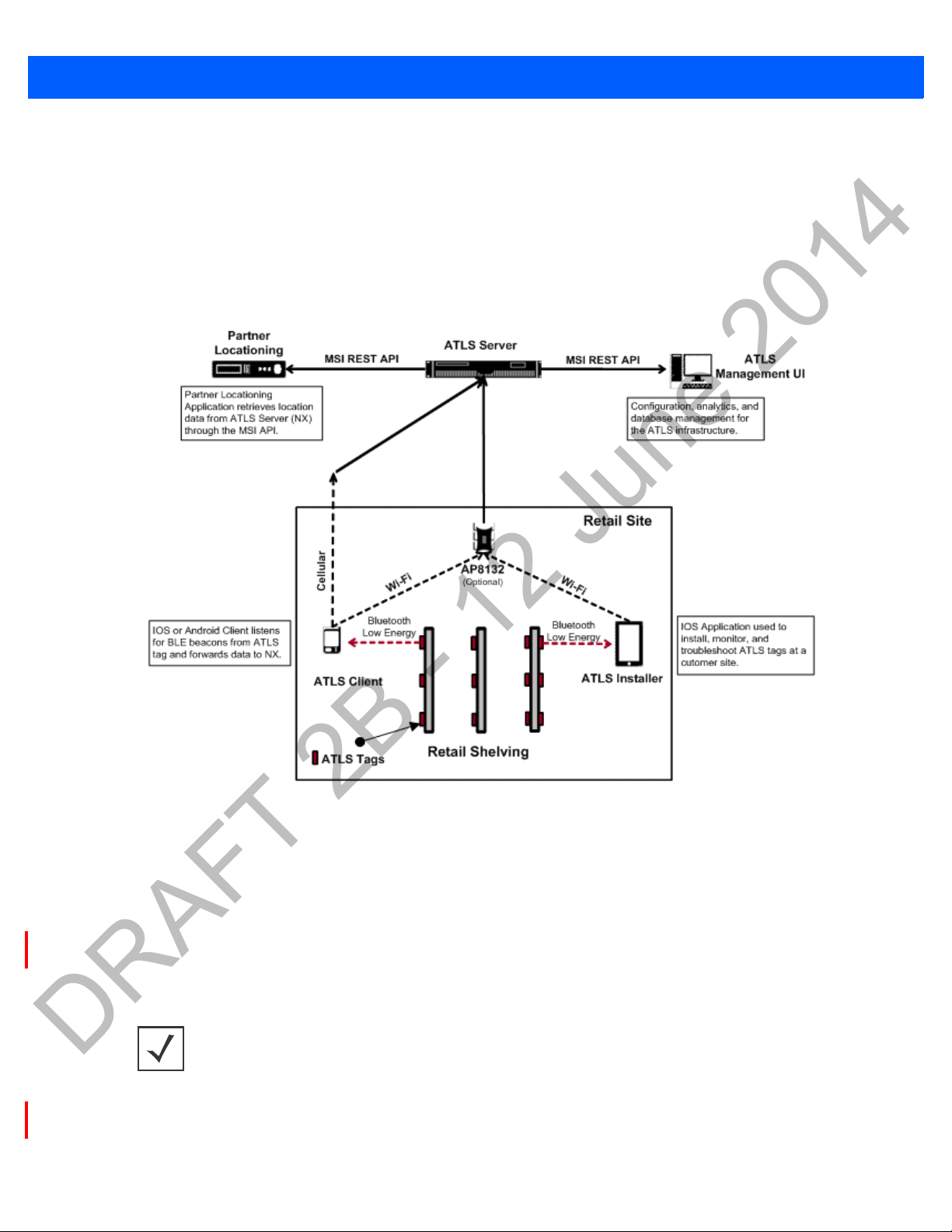
1.1 MPact Architecture
The MPact architecture is comprised of the following:
•
MPact Beacons
• MPact Server
• MPact Toolbox
• MPact Client SDK
Figure 1-1 MPact Typical Topology
1.1.1 MPact Beacons
MPact beacons are small, battery powered Bluetooth Low Energy (BLE) devices. Beacons are strategically placed in retail
environments where customer locationing is wanted. Beacons can be placed on existing retail shelving or mechanically
secured. MPact beacons utilize a Bluetooth 4.0 radio that periodically emits a signal over the course of at least two years (the
battery’s maximum lifespan). Depleted beacon batteries are easily replaced. A beacon’s Bluetooth beacon contains the
beacon’s ID and remaining battery life of the beacon to assist the administrator in managing the deployment area.
NOTE: Battery information is not available if using iBeacon mode. This guide assumes
the beacon is in
Beacon placements can be adjusted within a deployment floor plan, and depending on the mode selected, their battery life can
be tracked over time. Administrators can cursor over a beacon to assess the beacon’s remaining battery life. For more
information on Active View, refer to the
Battery Saving or MPact mode.
Motorola Solutions MPact Locations & Analytics Server Reference Guide.
Page 13
1.1.2 MPact Server
DRAFT 2B - 12 June 2014
The MPact Server, a location and analytics system can be installed on the Linux platform (Debian 7.3). It provides an interface
to install and maintain MPact beacon positions throughout a deployment site.
MPact Overview 1 - 3
The MPact Server receives its beacon data from customer’s devices moving
(beacon’s ID) is compared to other pre-configured beacon identifiers mapped to a specific location (the UUID is used to
distinguish one store from another and is set within the MPact management UI). When a match occurs, the MPact Server can
either place the mobile customer within a store or place the mobile customer in close proximity to specific products. The
customer’s location, the beacon’s proximity to specific products and the beacon’s remaining battery life are all stored on the
MPact Server’s local database for administrative retrieval and analysis.
The MPact Server application manages the MPact infrastructure and administrative
configure the site floor plans required for beacon placement and locationing, manage the association of beacons with specific
products, support beacon deployment and maintenance, and provide the visualization and analytics needed for both mobile
customer devices and beacons.
1.1.3 MPact Toolbox
The MPact Toolbox is an iPad application designed for easy beacon deployment and management. During a typical MPact
installation, an iPad is carried within a retail area to scan each beacon’s barcode during deployment. The handheld can also
validate existing beacon functionality at any time. Beacon deployments are administrated from the MPact Server (consisting
of beacon place holders and other attributes). An administrator user can add, modify or delete beacons and beacon place
holders from a site’s floor plan residing and displaying on the Installer. An administrator can add beacons or flash beacons as
their beacons are recognized. Beacon updates are stored on the MPact Server.
1.1.4 MPact Client SDK
The MPact Client SDK is a client library and is available in both IOS and Android versions. The client SDK integrates directly
into a partner application and allows it to listen for BLE emissions. Upon receiving a beacon emission, the client library sends
relevant information to the MPact Server. If the client receives data from more than one beacon within a given interval, the
utilized beacon is based on a beacon selection algorithm distributed between the client and the server. Communication
between the client library and the MPact Server is secured through SSL.
about a retail environment. The beacon identifier
framework. Use the MPact Server UI to
Page 14

1 - 4 Motorola Solutions MPact Location & Analytics Deployment Guide
DRAFT 2B - 12 June 2014
1.2 Browser Support
Use the following browsers with MPact Server:
• Internet Explorer, version 10 and higher
• Chrome, version 33 and higher
• Firefox, version 26 and higher
Page 15

CHAPTER 2 MPACT SERVER INSTALLATION
DRAFT 2B - 12 June 2014
AND SETUP
For more information, refer to the following:
Server Installation and Login
•
Server Configuration
•
• Tree Setu p
• Floor Plan Setup
• Category Configuration
• Beacon Place Holder Setup and Configuration
Page 16
2 - 2 Motorola Solutions MPact Location & Analytics Deployment Guide
DRAFT 2B - 12 June 2014
2.1 Server Installation and Login
The MPact Server is a Linux-based system. As a prerequisite to installing the MPact Server, ensure the server has the following
capacity:
•4 Cores
•8GB RAM
• 200GB disk space
• Operating System (OS): Debian 7.3 64-bit GUI
If an older version of MPact is installed on th
To uninstall the MPact Server:
1. Open a terminal on the
2. Get into the root account using su root.
3. Make sure
4. If
ls –l /bin/sh points to dash, enter the command, ln –fs bash /bin/sh.
5. Copy the server
6. For a server upgrade, stop the server ./nxstats stop under /usr/nuxi/script/bin.
After uninstalling the older version of the MPact Server
1. Change the folder to c
The server tar.gz file must be located in the /usr directory, otherwise the server cannot find the file.
2. Create a new folder, mkdir installer.
3. Change current folder to the installer folder, cd installer.
4. Download the ATLS tar.gz file to this folder or copy it from available location to the installer folder.
5. Untar tar.gz by
6. Once untared, change
7. Use python to start install process, python install.py.
ls –l /bin/sh points to bash, not dash.
tar xzvf <file name> under /usr, chmod –R 755 /usr/nuxi.
De
bian 7.3 GUI
tar.gz file into /usr:
d/usr.
dir to the install folder, cd ./nx_installer.
e system, the older version must be uninstalled.
.
, install the latest version.
8. Go to /usr/nuxi/script/bin.
9. To start the server, enter the command,./nxstat
Use the following paths for the MPact Server and base:
For the MPact Se
For the MPact Server database, the use the path: /
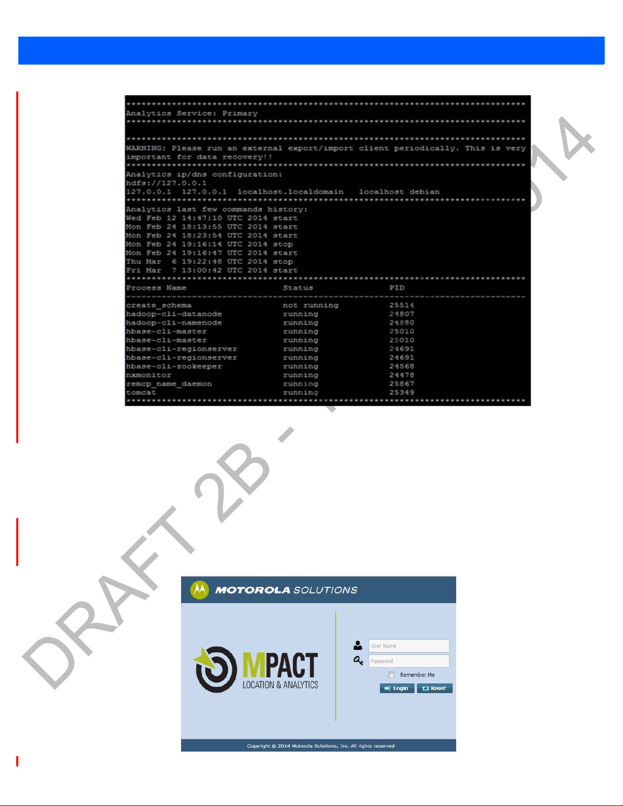
To check the status of the installation, use the following instructions.
1. To check for the expected results:
• Process (create_schema) is not running. This process is used to
• There should be 10 processes running.
rver, the use the path:
/usr/nuxi/*
s start.
var2/nuxi/data/*.
create the database for the first server installation.
Page 17
MPact Server Installation and Setup 2 - 3
DRAFT 2B - 12 June 2014
When the server installation is complete, login to the server and configure the system parameters.
2.1.1 Server Login
To login to the MPact Server remotely:
1. Go to
2. Enter the
<S
• Select
• Select
erver IP>: 80/atls
User Name (superuser is the default) and Password (motorola is the default), and select Login.
Remember Me
Reset
Figure 2-1 MPact Deployment - Expected Results
(use either Chrome or Firefox).
to use the same credentials in subsequent logins.
to clear the fields and start again.
Figure 2-2 MPact Server - Login
Page 18
2 - 4 Motorola Solutions MPact Location & Analytics Deployment Guide
DRAFT 2B - 12 June 2014
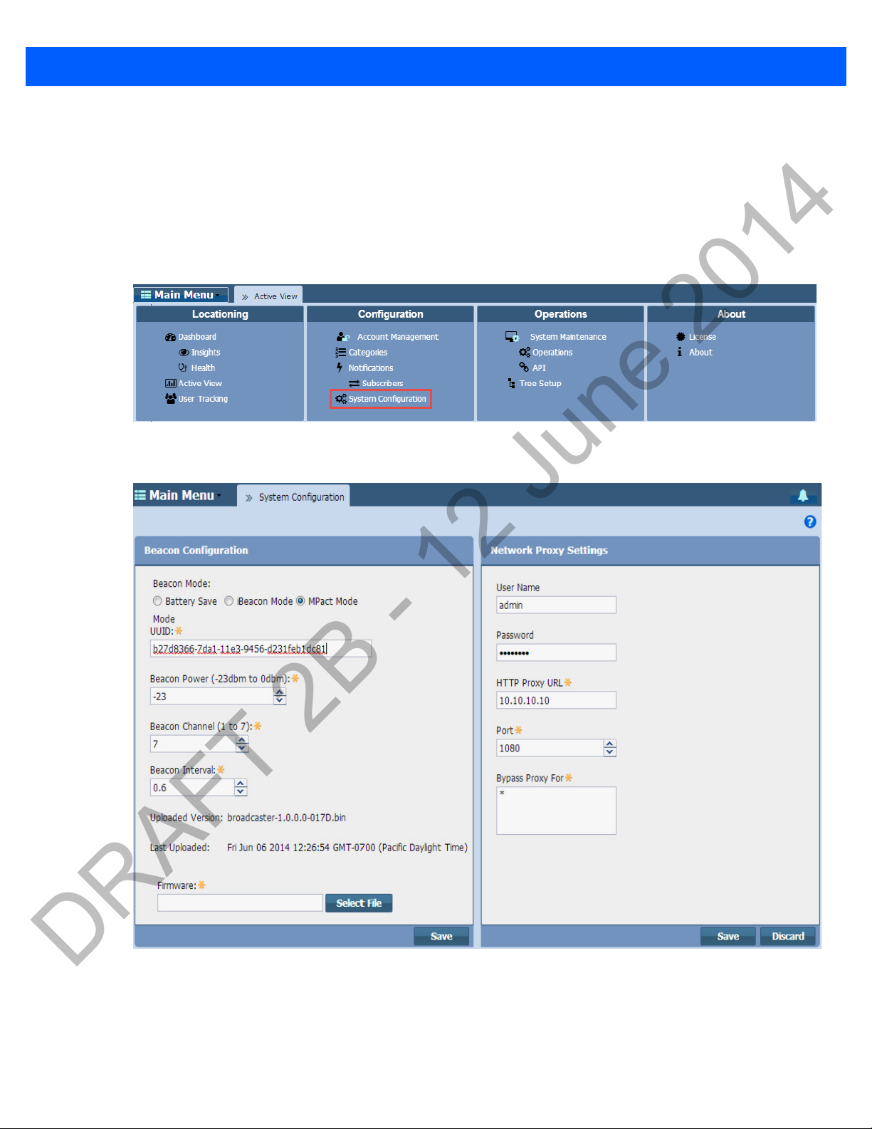
2.2 Server Configuration
Use
System Configuration for the administration of beacon settings defined globally on the MPact Server. The beacon
settings are then pushed to selected beacons as their respective configurations warrant. Beacon configuration settings must
be set accurately in the MPact Server before they can be provisioned to an MPact Toolbox supported iPad.
To administrate the system configuration:
1. Select
2. Modify the System Configuration parameters as required.
System Configuration under the Configuration main menu item.
Figure 2-3 MPact Server System Configuration - System Configuration
Figure 2-4 MPact Server - System Configuration
Page 19
MPact Server Installation and Setup 2 - 5
DRAFT 2B - 12 June 2014
3. Refer to the following table to modify the Beacon Configuration parameters:
Beacon Mode Set the mode defining how beacons are emitted from MPact beacons. Supported modes
include
The
beacon as small as possible (the beacon contains the minimal amount of information needed
to support MPact server functions). An MPact beacon contains the Motorola Solutions
registered manufacturing ID, beacon ID and a single byte representing the percentage of
battery life remaining (0-100%).
The
7.0). There are three data fields Apple has made available to iOS applications, a UUID for
device identification, a Major component for device class and a Minor component for more
refined information like product category.
The
could be the same for each device on the first floor or a particular department store (0-65525).
The
If the major or minor values display in red, they have been pre-set from the MPact Server and
do not require modification, they just need to be pushed to the device.
The
been defined so MPact data can be conveyed as being compatible with the MPact server. No
input is required.
Battery Saving, iBeacon and MPact.
Battery Saving format, the default setting, is optimized for battery life by making the
iBeacon format was created by Apple for use in iOS devices (beginning with iOS version
Major field is a 2 byte field for identifying the device class. For example, the Major value
Minor field is a 2 byte field for more refined information, like product category (0-65535).
MPact beacon format uses the iBeacon format, however, the Major and Minor fields have
UUID (16 bytes) 16 byte hex character string that defines the purpose of the device. The UUID classification is
meant to be broad. For example, a UUID could identify a beacon was owned by Starbucks.
Beacon Power
(-23 dBm to O dBm)
Beacon Channel
(1 to 7)
Beacon Interval
(100 ms to 1000 ms)
Uploaded Version
Last Uploaded
Firmware
Beaconing output power is set from -23 to 0 dBm.
Channel mask is set from 1-7 to apply an operation channel restriction to beacon
transmissions.
From 100ms to 1000ms in 100 ms increments for a beacon's emission. The default is 600ms.
The shorter the interval, the shorter the beacon's battery life. However, shorter intervals result
in increased accuracy.
Either blank or lists the firmware version last utilized for beacon uploads by the MPact server
(for example, broadcaster-1.0.0.0-00xD.bin.
Either blank or lists the date and time the most recent firmware version (the version listed in
the Uploaded Version field) is pushed to the beacons.
Place the cursor inside the field to browse to the latest beacon firmware file. Choose Select
to launch a screen for navigating the system for a target firmware file for subsequent
File
beacon uploads. Once selected, the complete relative path for the file displays.
Note: Some beacon models do not allow for any changes in firmware.
4. Select Save to commit these beacon configuration settings for subsequent download to beacons.
Page 20
2 - 6 Motorola Solutions MPact Location & Analytics Deployment Guide
DRAFT 2B - 12 June 2014
5. Set the Network Proxy Settings to define how MPact server event subscribers receive their defined notifications over
the MPact server.
HTTP Proxy Settings Set the Web domain location for the destination of uniquely defined subscriber event
notifications (for example, www.hostname-example.com).
Port Use the spinner control to set the virtual port integer for the connection between the MPact
server and the defined proxy or IP address.
Bypass Proxy Optionally, bypass a proxy Web domain by providing a numerical IP address for the recipient
server receiving event notifications on behalf of the subscribers.
6. Select
Save to commit these subscriber notification connection settings to the MPact server.
NOTE: If the uploaded version does not change after saving the configuration, try logging
out and re-login to MPact UI or repeating the configuration steps.
Page 21
MPact Server Installation and Setup 2 - 7
DRAFT 2B - 12 June 2014
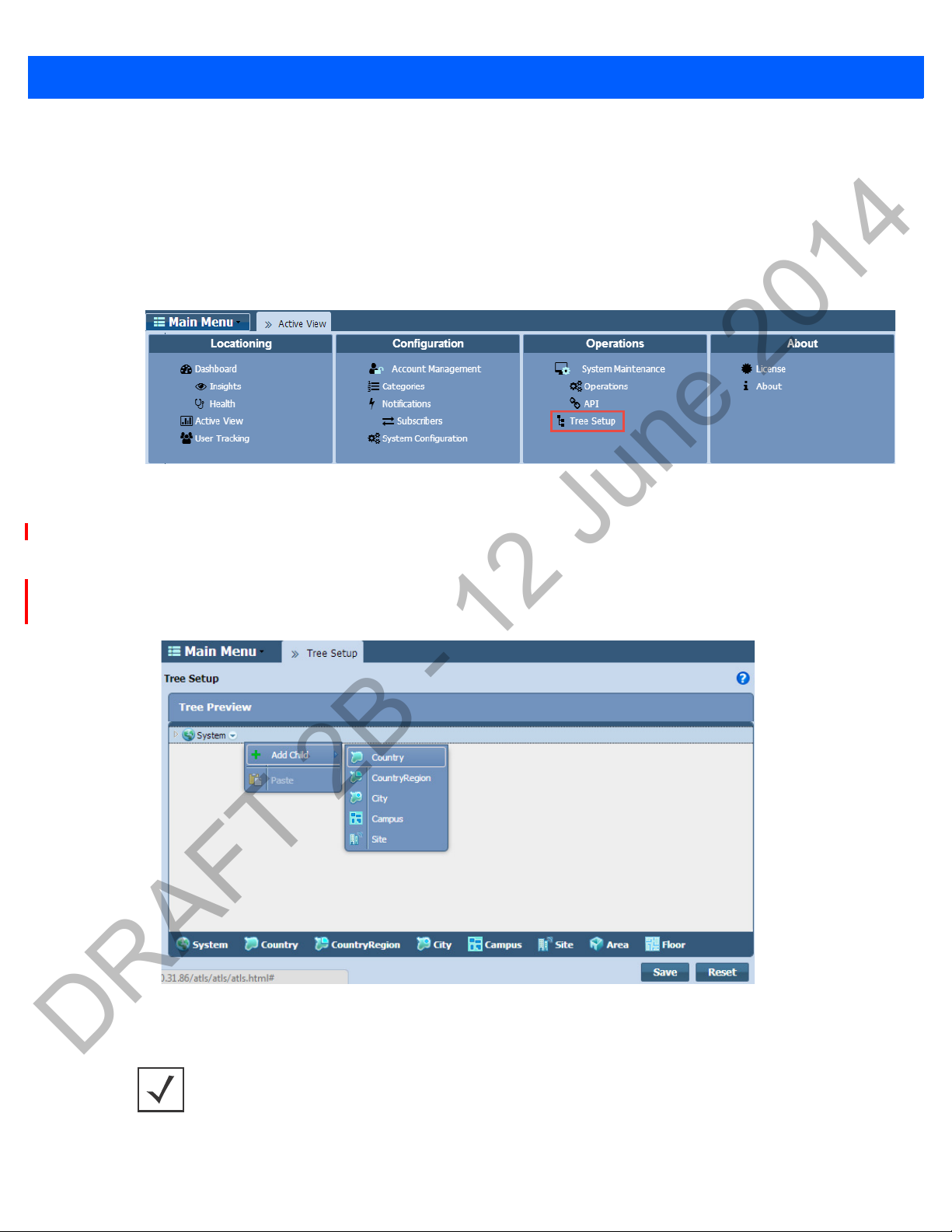
2.3 Tree Setup
Use
Tree Setu p to build the tree hierarchy for each store site location on a global map. A tree hierarchy is built from a global
site location down to each floor in a building, including floor plans for each floor in a building. After the tree is saved,
configurations are added to the system for beacon deployment on the floors of each site.
To administrate the MPact tree setup:
1. Select
2. From the System drop-down menu, select Add Child and drag the cursor over to the node to add the required node. Build
T
ree Setup
the hierarchy for
Keep the following in mind when creating the tree:
• You do not have to create a
• At the end of every tree setup there must be a
under the Operations main menu item.
Figure 2-5 MPact Server UI Tree Setup
Country, Country Region, City, Campus, Site, Area and Floor, as needed.
Coun
before creating a Site.
try
Floor.
Figure 2-6 MPact Server UI Tree Setup - Adding Tree Nodes
NOTE: When building the tree hierarchy, the following characters are invalid:
-q- $ * < > # ~. All other characters, including space, are valid.
Page 22

2 - 8 Motorola Solutions MPact Location & Analytics Deployment Guide
DRAFT 2B - 12 June 2014
3. From the Add Node dialog box, enter a node Name and select OK.
Figure 2-7 MPact Server UI Tree Setup - Add Node Dialog Box
4. Continue adding nodes as required to the Floor level.
5. When finished, select
The newly created tree displays in the
hierarchy in relation to the existing tree setups. The next step is to add a floor plan to the floor.
Save.
Tree Preview area. The node is automatically placed in its respective location the
Page 23

2.4 Floor Plan Setup
DRAFT 2B - 12 June 2014
MPact Server Installation and Setup 2 - 9
After the tree setup is built down to the site floor level, load a
floors along with their floor plans. Optimally, a floor plan should be an accurate representation of the retail floor layout, which
includes broad category labeling for items in the area. For example, a grocery store would have labels such as dairy, meats,
vegetables etc.
Floor plan images have the following constraints:
Forma
•
•
To administrate a floor plan:
1. Select Tree Setup under the Operations main menu item.
2. From the
3. From the
t
: JPEG/JPG/PNG
Ma
ximum resolution
Tree Prev iew area, open the tree hierarchy down to the floor level.
Floor drop-down menu, select Edit Floor Plan.
: 10,000 x 10,000 pixel ~ 20MB
Floor Plan image to the site’s Floor. A site can have multiple
Figure 2-8 MPact Server UI Tree Setup - Edit Floor Plan
Page 24

2 - 10 Motorola Solutions MPact Location & Analytics Deployment Guide
DRAFT 2B - 12 June 2014
4. Select the Load Map button to browse to and select a floor plan image of the site’s floor.
Figure 2-9 MPact Server UI Tree Setup - Load Floor Plan
5. Set the physical size of the area the floor plan represents:
• Unit: Select either Meter or Feet.
Width:
•
•
6. Select
Enter the width of the floor, the default is set to 400.
Width:
Enter the height of the floor, the default is set to 200.
Save.
Figure 2-10 MPact Server UI Tree Setup - Load Floor Plan
Page 25

2.5 Category Configuration
DRAFT 2B - 12 June 2014
MPact Server Installation and Setup 2 - 11
Use the
traffic and dwell time data reported by the system. MPact events are tied to categories and category fields. When beacons are
skillfully deployed, they are associated with the physical location of a specific product category within a floor plan. As client
users move about the floor, their beacon visits and dwell times can be associated with the product categories associated with
the beacon’s location.
To administrate categories:
1. Select
2. From the
Categories functions to group product family items logically and better apply significance to the locationing, customer
Categories under the Configuration main menu item.
Figure 2-11 MPact Server - Categories
Existing categories display along the left-hand side of the screen.
Category List, select a category to display its Category Values (product names) administratively aligned with
that category’s beacon location on a site’s floor plan.
Figure 2-12 MPact Server - Categories
In the example above, the Category, Beauty, located on the left-hand side of the screen, is aligned with the Category
Values
represent the products grouped for tracking under the parent category,
listed on the right-hand side of the screen: Deodorant, Shampoo and Soap. In this example, Category Values
Beauty.
Page 26

2 - 12 Motorola Solutions MPact Location & Analytics Deployment Guide
DRAFT 2B - 12 June 2014
2.5.0.1 Category Creation and Modification
Use the
existing categories.
To create a new category:
1. Select the
+Create New Category button to add new categories to the Category List and the Edit drop-down menu to modify
+Crea
te New Category
Figure 2-13 MPact Server - Category Creation and Modification
button.
2. Enter a
3. To modify an existing category, select a category from the Category List.
4. From the
Category Name and Category Description and click Ok to implement the updates.
Figure 2-14 MPact Server - Add Category
Edit drop-down menu, select one of the following actions and select Ok to implement the changes.
Edit Allows changes to the category’s name and description.
Copy Places a duplicate copy of the category and its category values immediately below the existing category
name.
Delete Deletes the category and associated category values. Motorola Solutions recommends an administrator
export and archive a category’s defined values in Comma Separated Value (CSV) file format before deleting
a category.
Page 27

2.5.0.2 Category Value Creation and Modification
DRAFT 2B - 12 June 2014
MPact Server Installation and Setup 2 - 13
Use the
existing category values. Ensure any values added make up a logical group of products, well suited for the client traffic and
dwell time reported under its parent category’s beacon deployment location.
To create new category values:
+Add New Value button to add new values to existing Category Values and the Delete drop-down menu to modify
Figure 2-15 MPact Server - Category Value Creation and Modification
1. Select the
2. Enter a Name and Description and click Update to implement the value.
3. To modify existing category values, select the check box for an existing category value.
+Ad
d New Value
button.
Figure 2-16 MPact Server - Add New Value
Select the
D
drop-down menu to select one of the following modification actions:
elete
Edit Allows changes to the category value name and description.
Page 28

2 - 14 Motorola Solutions MPact Location & Analytics Deployment Guide
DRAFT 2B - 12 June 2014
Copy Places a duplicate copy of the category value immediately below the existing category value.
Delete Deletes the category value.
4. Select Ok to implement the changes to the category value list.
Page 29

MPact Server Installation and Setup 2 - 15
DRAFT 2B - 12 June 2014
2.6 Beacon Place Holder Setup and Configuration
Use
Place Holders to secure a beacon’s physical position on a site floor plan. The beacon place holder contains the beacon’s XAxis and Y-Axis coordinates and the beacon’s direction and antenna pattern.
The optimal floor plan coverage has beacon place holders setup
seen in the image below. Placing them any closer can cause the beacon’s signal to bounce between beacon locations.
Figure 2-17 MPact Server - Beacon Place Holder Coverage
When placing beacon place holders on the floor plan, ensure the place holder is located with respect to the selected product
category. Place holders can be strategically placed on end caps, aisle entrances, and at seasonal promotional displays.
Product
Notifications for special promotional offers. Notifications are configured to notify a subscriber when a client action is
performed, for example, client entry, client exit or dwell time.
There are two methods for setting up beacon place holder positions on a floor plan:
Ca
tegories
• Manual setup: Used for smaller deployment projects.
and Category Values are assigned to the beacon place holder, which allows Subscribers to receive
two meters apart and staggered on opposite sides of an aisle,
• CSV file import setup: Used for large deployment projects.
Page 30

2 - 16 Motorola Solutions MPact Location & Analytics Deployment Guide
DRAFT 2B - 12 June 2014
2.6.1 Place Holder Manual Setup
Manual place holder setup can be used for smaller deployments.
To manually set up a beacon’s place holder position:
1. Select Active View under the Locationing main menu.
2. From the
been placed on the global map.
3. Use the zoom feature in the upper left-hand corner of the right pane to zoom in to the appropriate site location.
4. Drag and drop one or more of the
Tree Hierarchy area on the left-hand side, select the System node to display the Unplaced Sites that have not yet
Unplaced Sites to the appropriate site location on the global map.
Figure 2-18 MPact Server - Site Map Placement
5. Expand the Tree Hierarchy on the left-hand pane and select the corresponding site floor for the deployment.
Page 31

6. Select the Edit Mode button to the far-right on the tool bar.
DRAFT 2B - 12 June 2014
MPact Server Installation and Setup 2 - 17
Figure 2-19 MPact Server - Floor Plan Edit Mode
7. From the Positions drop-down menu, select Add Position.
Figure 2-20 MPact Server Active View - Add Position
8. Select the intended location of the place holder by double-clicking on the location on the floor plan.
Page 32

2 - 18 Motorola Solutions MPact Location & Analytics Deployment Guide
DRAFT 2B - 12 June 2014
The Add Position dialog box displays with the Position Location auto-populated with the place holder’s
X-Axis and Y-Axis positions on the floor plan.
Figure 2-21 MPact Server Active View - Add Place Holder Position to the Site Floor
9. Configure the Place Holder options:
Position Name Enter a XX character maximum Position Name for the beacon place holder location.
Position Description Optionally, provide a XX character maximum description.
Position Location
(meters)
Beacon Configuration Major: Set from 0 - 9. A Major component for device class and a Minor component for more
Position Categories Select Add Category to assign a Category to the beacon’s position. Category selections are
The auto-populated X and Y axis values are relative (zero) to the upper left-hand corner of the
floor plan and increase to the right (X) and down (Y) from the left-hand corner of the floor plan.
(The Position Location was auto-populated earlier by double-clicking on the floor plan
location.)
refined information like product category. The Major field is a 2 byte field for identifying the
device class. For example, the Major value could be the same for each device on the first floor
or a particular department store.
Minor: Set from 0 - 9. In iBeacon mode, the Minor field is a 2 byte field for more refined
information, like product category. It consists of the last byte of the MAC address.
defined and configured in Categories, under the Configuration main menu item of the Server.
For more information on defining and configuring Categories, see
Location & Analytics Server Reference Guide
.
Motorola Solutions MPact
Page 33

MPact Server Installation and Setup 2 - 19
DRAFT 2B - 12 June 2014
Advanced Beacon
Settings
10. Select Save to commit the updates, Reset to revert to the last saved configuration or Cancel to close and exit the screen.
11. Repeat this process to manually add more place holders. Once place holders have been added to the floor plan, beacons
can be installed (scanned) and configured.
Antenna Pattern: Use the drop-down menu to set whether the antenna pattern is a Circle (360
degree omnidirectional) pattern or a Semi-Ellipse (180 degree direction) pattern.
Beacon ID: The ID of the beacon receiving advanced settings.
Degrees: Set from 0 to 360 degrees.
Beacon Offset: Set from 1 to 4 meters.
2.6.2 Beacon Place Holder CSV File Import Setup
For large deployments, a CSV file is used to setup beacon place holders on a site floor plan on the MPact Server (instead of
manual setup).
To import the CSV file to the site
1. Select
API
under the Operations main menu.
floor plan in the server:
Figure 2-22 MPact Server System Maintenance- CSV File Import
Page 34

2 - 20 Motorola Solutions MPact Location & Analytics Deployment Guide
DRAFT 2B - 12 June 2014
2. Select the Export/Import button.
Figure 2-23 MPact Server System Maintenance- CSV Place Holder Import
3. Select the Import button for Place Holder.
4. When the
5. Click Save to save CSV file data to the server.
Upload CSV popup box displays, browse to and select the CSV file, and select the Upload button.
Figure 2-24 MPact Server System Maintenance - Upload CSV
Page 35

CHAPTER 3 MPACT TOOLBOX
DRAFT 2B - 12 June 2014
INSTALLATION AND SETUP
The MPact Toolbox is an iPad application designed for beacon installation and maintenance at the area beacons are deployed.
The iPad is carried within the deployment area to scan a beacon’s barcode when the beacon is first installed to add its position
attributes and validate existing beacons are working as expected. A toolbox equipped iPad reads beacon installations from the
MPact Server, which consists of beacon positions, IDs and other attributes. Users can optionally add, modify or delete beacons
and beacon positions from a store map displayed on the installer (essentially adding beacons by scanning a barcode and
flashing beacons as their beacons are recognized).
All beacon updates are stored on the MPact Server. The MPact Toolbox mediates between an MPact Server and an MPact
con. The toolbox can pull configuration and firmware information from the MPact Server and update a beacon as
bea
deployment objectives require. The toolbox records beacon placements and updates the server. The toolbox supports three
beaconing beacon modes: Battery Save, iBeacon and MPact.
To install the MPact Toolbox application, re
MPact Server configurations to the MPact Toolbox application on the iPad.
For more information, refer to the following:
Toolbox System Requirements
•
• Toolbox Installation
• Toolbox Login and Setup
gister the iPad with the TestFlight Web site. Once installed, download the latest
Page 36

3 - 2 Motorola Solutions MPact Location & Analytics Deployment Guide
DRAFT 2B - 12 June 2014
3.1 Toolbox System Requirements
The MPact Toolbox can be run with the following platforms:
• iOS versions 6.1 - Only supports the Battery Save beaconing mode
• iOS versions 7.0 and higher - Supports all three MPact beacon modes (Battery Save, iBeacon and MPact)
3.1.1 iPad Hardware Limitations
The iPad has the following limitations:
iPad Version Model CPU RAM Limitation
iPad Min
(First Generation)
iPad 3 A1416 32 Bit 1GB Floor plan image should not exceed 200 MB
iPad 4 A1458 32 Bit 1GB Floor plan image should not exceed 200 MB
A1432 32 Bit 512 MB Floor plan image should not exceed 3MB in
ile size
f
le size
in fi
le size
in fi
Page 37

MPact Toolbox Installation and Setup 3 - 3
DRAFT 2B - 12 June 2014
3.2 Toolbox Installation
The MPact Toolbox software application is installed on an iPad and is used to locate beacons in the system, download firmware
to the beacons, and configure the beacons. The MPact Toolbox is used to maintain beacon positions and reconfigure beacons
when changes are made to the retail site floor.
The MPact Toolbox software application is installed on an iPad us
The MPact Toolbox application supports the iPad iOS 6.0 and 7.0 operating systems.
ing the TestFlight web site (only for beta).
3.2.1 TestFlight Mobile Platform Account Sign Up (Use for Beta Only)
The TestFlight mobile platform is used to install and maintain the Toolbox application. Prior to using the TestFlight web site,
provide a business email to the Motorola MPact team and request an invitation to sign up for the TestFlight mobile platform.
Invitations are provided only to qualified developers and IT personnel.
To sign-up for the TestFlight account:
1. From the invitation email received fr
account.
2. Follow the instructional wizard to complete the registration.
Use this account to install and maintain the MPact Toolbox application during the beta period.
om the Motorola MPact team,
Accept the invite using a new or existing TestFlight
3.2.2 MPact Toolbox Installation (Use for Beta Only)
Use the install wizard provided to install the MPact Toolbox.
To install the Toolbox software application:
1. Using an iPad, logon to https://www.testflightapp.com using the newly created TestFlight account.
Page 38

3 - 4 Motorola Solutions MPact Location & Analytics Deployment Guide
DRAFT 2B - 12 June 2014
2. Select the Install button to install the TestFlight configuration profile on the iPad.
Figure 3-1 MPact Toolbox Installation - Install Profile
Page 39

3. Select the Install Now button to change the iPad settings.
DRAFT 2B - 12 June 2014
MPact Toolbox Installation and Setup 3 - 5
Figure 3-2 MPact Toolbox Installation - Confirm Install Profile
4. Select the Install Now button to install the profile settings on your iPad.
Page 40

3 - 6 Motorola Solutions MPact Location & Analytics Deployment Guide
DRAFT 2B - 12 June 2014
Figure 3-3 MPact Toolbox Installation - Profile Installation Confirmation
Page 41

5. Select the View All Apps button.
DRAFT 2B - 12 June 2014
MPact Toolbox Installation and Setup 3 - 7
Figure 3-4 MPact Toolbox Installation - TestFlight Device Connected
Page 42

3 - 8 Motorola Solutions MPact Location & Analytics Deployment Guide
DRAFT 2B - 12 June 2014
6. Select the Continue button to agree to the Terms of Use & Privacy Policy Update.
Figure 3-5 MPact Toolbox Installation - Terms of Use and Privacy Policy Update
Page 43

7. Select the Install button to install the To ol bo x application.
DRAFT 2B - 12 June 2014
MPact Toolbox Installation and Setup 3 - 9
Figure 3-6 MPact Toolbox Installation - Install the Toolbox Application
8. Select the Install button to continue with the installation.
Figure 3-7 MPact Toolbox Installation
Page 44

3 - 10 Motorola Solutions MPact Location & Analytics Deployment Guide
DRAFT 2B - 12 June 2014
9. Select the Continue button complete the installation process and open the application.
Figure 3-8 MPact Toolbox Installation Complete
The application is installed on the iPad and ready for login.
Page 45

MPact Toolbox Installation and Setup 3 - 11
DRAFT 2B - 12 June 2014
3.3 Toolbox Login and Setup
Login to the MPact Toolbox application to automatically allow the server to download deployment information to the Toolbox.
All data displayed in the ToolBox is fetched from the server, which includes settings for site maps, floor plans, and beacon
related configurations.
To login to the MPact Toolbox application:
1. From your iPad, select the Toolbox icon.
Figure 3-9 MPact Toolbox Icon
The first time logging on, the login screen displays prompting for a username, password and the server port for data
transfers between MPact beacons and the administrative MPact Server.
Figure 3-10 MPact Client Toolbox - Login
2. Enter superuser as the default Username and motorola as the default Password.
If changing the default password, enter a 32 character maximum alphanumeric password consisting of ASCII characters
with no spaces.
Page 46

3 - 12 Motorola Solutions MPact Location & Analytics Deployment Guide
DRAFT 2B - 12 June 2014
3. Provide the numeric server IP address and port designated for traffic for MPact beacons. This is a non IPv6 address.
The first time logging into the MPact Toolbox, the following are acceptable IP addresses for logging on to the server:
• http://IP/atls/atls/atls.html
• http://IP:80/atls/atls/atls.html
• https://IP/atls/atls/atls.html
• https://IP:443/atls/atls/atls.html
NOTE: T
/var2/muxi/cert/nuxi.jks. The nuxi.jks certificate file is provided for https connections. To
use a company generated certificate, rename the certificate to
directory.
4. Select the
Upon successful login, the toolbox home page displays. The first time you log onto the MPact Toolbox application, wait for
the server to download toolbox data to the iPad, which takes about a minute. The indicator in the upper left corner of the
screen displays the progress of the download.
o enable the https connection, a certificate is required in the following directory:
nuxi.jks and put it in the
Login bu
tton. Select
Remember Me to use the same credentials in subsequent logins.
Figure 3-11 MPact Toolbox Home Page - Beacon Installation
The Home page displays beacon setup and maintenance activities:
Installation Select the Installation ic
Individual floors can be administrated for specific beacon deployment activities.
Maintenance Select the Maintenance option to validate the operation and functionality of existing beacon
deployments.
Beacon Firmware Select Beacon Firmware to launch a utility for upgrading beacon firmware.
on to display a site map containing building and floor plan images.
Page 47

MPact Toolbox Installation and Setup 3 - 13
DRAFT 2B - 12 June 2014
Beacon Configure Select Beacon Configure to wirelessly set the deployment settings for beacons.
Settings Refer to the Settings option to administrate the connection settings between the handheld
device and the MPact Server.
Page 48

3 - 14 Motorola Solutions MPact Location & Analytics Deployment Guide
DRAFT 2B - 12 June 2014
Page 49

CHAPTER 4 BEACON INSTALLATION AND
DRAFT 2B - 12 June 2014
ACTIVATION
The MPact Toolbox allows beacons to be installed and activated from the deployment site and allows the MPact Server to
receive client device site data in real time.
For more information, refer to the following:
•
Beacon Installation
• Beacon Activation
Page 50

4 - 2 Motorola Solutions MPact Location & Analytics Deployment Guide
DRAFT 2B - 12 June 2014
4.1 Beacon Installation
Use the iPad to scan the beacon’s bar code and connect the beacon to the floor plan location in the MPact Toolbox.
To connect the beacon hardware to the MPact Toolbox application:
1. From the toolbox home page, select
A global map displays the existing site locations.
Installation.
Figure 4-1 MPact Toolbox - Deployment Site Map
2. Use the Close button located in the lower left-had corner of the screen to close the map and display the Site Hierarchy
screen.
Page 51

Beacon Installation and Activation 4 - 3
DRAFT 2B - 12 June 2014
The Site Hierarchy screen displays deployment sites downloaded from the MPact Server.
Figure 4-2 MPact Toolbox - Site Hierarchy
3. Select a site and drill down to the deployment floor plan where the beacons are being deployed.
4. Select the intended Place Holder for the beacon that is being deployed.
The image below shows an empty circle on the floor plan with a red square, an intended Place Holder for a beacon.
Figure 4-3 MPact Toolbox Home Page - Beacon Place Holder
Page 52

4 - 4 Motorola Solutions MPact Location & Analytics Deployment Guide
DRAFT 2B - 12 June 2014
5. With the MPact Toolbox set to scan mode, scan the bar code on the beacon housing by aiming the iPad camera within 3-4
inches of the beacon’s bar code until a green square appears.
Figure 4-4 MPact Toolbox Home Page - Beacon Place Holder
A green square appears in the capture area and the decoded barcode displays as a numeric ID at the bottom of the page.
Figure 4-5 Beacon Barcode Scanning
Page 53

6. When the installation popup displays, select Scan Barcode.
DRAFT 2B - 12 June 2014
Figure 4-6 MPact Toolbox - Scan Barcode
Beacon Installation and Activation 4 - 5
NOTE: If the beacons have been pre-configured on the server with a specific ID, be sure
to select the proper beacon with the correct ID that matches what is shown on the
beacon installation popup display.
7. Select Done, then select Save.
Within twenty seconds, the beacon connects to the toolbox. A successful installation results in the beacon being located
in the intended place holder position and in an inactive state; the interior of the beacon is grey.
Figure 4-7 MPact Toolbox - Successful Beacon Installation
Page 54

4 - 6 Motorola Solutions MPact Location & Analytics Deployment Guide
DRAFT 2B - 12 June 2014
4.2 Beacon Activation
After the beacon is connected to the MPact Toolbox, the beacon must be activated. The beacon is activated by opening and
closing the beacon’s housing (hardware), where the battery is located. These actions allow the beacon to switch from
transmitting mode to receiving mode, enabling the location and tracking of the client’s device, and allowing offers to be receive
by the client’s device.
To activate the beacon, pull the mylar strip off of the beacon housing, shown below, to the left of the housing.
Figure 4-8 Beacon Activation
When the beacon is in an active state, the beacon turns green with a blue dot, shown below. The blue dot indicates the
direction of the beacon’s signal, which should face toward the middle of the aisle.
Figure 4-9 MPact Toolbox Home Page - Active Beacon
8. Attach the beacon to the shelf or other similar hardware and move on to deploy the next beacon.
For more information on mounting beacon hardware to shelves and other surfaces, see
Beacon Hardware Installation.
Appendix A,
Page 55

APPENDIX BEACON HARDWARE
DRAFT 2B - 12 June 2014
INSTALLATION
As a prerequisite to installing beacon hardware, the following setup processes must be complete:
• MPact Server installation and setup is complete
For more information see,
• MPact Toolbox installation and setup is complete
For more information see,
For information on beacon power usage and scalability, see Beacon Battery Life
For instructions on installing beacon and bracket hardware models on deployment site floors, see the following:
•
Beacon Part Number: MPACT-T1B20-000-WR (Model # ATLS-T1B)
• Beacon Part Number: MPACT-T1B10-000-WR (Model # ATLS-T1B)
• Beacon Hardware Regulatory Information
Lozier Shelves
The brackets can be used on the following styles of Lozier shelves:
MPact Server Installation and Setup on page 2-1
MPact Toolbox Installation and Setup on page 3-1
• Lozier TL Shelf
• DL Shelf
• HL Shelf
• Standard Base Deck
Page 56

A - 2 Motorola Solutions MPact Location & Analytics Deployment Guide
DRAFT 2B - 12 June 2014
A.1 Beacon Battery Life
For beacon battery life information, refer to the following table.
Advertising Interval Broa
-30 dBm [low] -4dBm +4 dBm [high]
200 ms
500 ms [short]
600 ms
1000 ms
2000 ms [long]
160 days 140 days 104 days
40 days 35 days 26 days
1.9 years 1 year 300 days
1.2 years 1.7 years 1.3 years
3.3 years 3 years 2.3 years
dcasting
Power
Page 57

Appendix A Customer Support A - 3
DRAFT 2B - 12 June 2014
A.2 Beacon Part Number: MPACT-T1B20-000-WR (Model # ATLS-T1B)
As a prerequisite, the following hardware items are required to mount the tie-wrap style beacon housing to a pole or
similar structure:
• Beacon (tie-wrap style housing), part number - MPACT-T1B20-000-WR
• Plastic tie wraps for attaching each beacon housing to the shelf
Installing the Tie-Wrap Style Beacon
Tie-wrap beacon housings are designed to attach to vertical or horizontal poles or similar mounting surfaces.In the image
below, there are openings located on the back of the beacon housing allowing a tie wrap to be inserted through the
openings and wrapped around a pole or similar structure.
Notice there is an up arrow located on the middle of the beacon housing. This up arrow shows the orientation for the
be
acon to rest in order for the beacon to function properly. In addition to the beacon’s up arrow orientation, the smooth
front of the beacon should face out, so that the beacon’s directional pattern faces out toward the aisle where the retail
customer is located, not facing over the shelves.
Figure A-1 Tie Wrap Style Beacon - Part Number - MPACT-T1B20-000-WR
To mount the tie wrap style beacon to a pole or similar structure:
1. Using a site floor plan, determine the exact Place Holder
Physically mounting the beacon should be done in conjunction
with the place holder in the MPact Toolbox application. After the technician associates the beacon with the place
holder, the beacon is physically affixed to a poll or similar structure on the site floor.
2. Mount the beacon to a pole or similar
When mounting the beacon, make sure the bar code label is face up toward the ceiling and the front of the beacon is
facing
outward toward the aisle where the retail customer is expected to dwell.
structure using the plastic tie wrap.
location on the site floor plan for the beacon.
with the software process of associating the beacon
Page 58

A - 4 Motorola Solutions MPact Location & Analytics Deployment Guide
DRAFT 2B - 12 June 2014
A.3 Beacon Part Number: MPACT-T1B10-000-WR (Model # ATLS-T1B)
As a prerequisite, the following hardware items are required to a Lozier style shelving unit:
• Lozier style shelving units are in place
• Beacon: Part number - MPACT-T1B10-000-WR
• Bracket mount, one of the following:
• MPACT Metal Lozier Bracket: Part number MPACT-A1O10-004-WR
• MPACT Plastic Lozier Bracket: Part number MPACT-A1O10-001-WR
• Phillips head screw driver for mounting the bracket (metal brackets only) to the Lozier shelf
Installing the Universal Style Beacon
The image below shows a universal style beacon housing. While there is no up arrow on this beacon’s housing, the
beacon is oriented similar to the tie wrap style of beacon housing (see
(Model # ATLS-T1B) on page A-3
).
Beacon Part Number: MPACT-T1B20-000-WR
Figure A-2 Tie Wrap Style Beacon - MPACT-T1B10-000-WR
The beacon and bracket are mounted on the shelf so the beacon is up and facing out toward the aisle so the signal
emitted by the beacon can be picked up by the retail customer’s phone application. The bracket mounts directly onto
the retail shelf. There are two styles of bracket mounts from which to choose, one is metal and one is plastic.
Page 59

Appendix A Customer Support A - 5
DRAFT 2B - 12 June 2014
Figure A-3 Universal Style Metal Bracket - Part Number MPACT-A1O10-004-WR
Figure A-4 Universal Style Plastic Bracket with Beacon- Bracket Part Number MPACT-A1O10-001-WR
To mount the universal style beacon to a Lozier shelf:
1. From the MPact Toolbox, select a site floor plan and beacon
2. Mount the universal beacon shelf-bracket on the shelf:
• Metal brackets: Fit in place and tighten onto the shelving unit using a phillips-head screw driver.
• Plastic brackets: Fit in place and snap onto the shelving unit.
Place
Holder
location for the beacon installation.
3. Fit the beacon’s universal style housing into the bracket and turn the beacon housing clockwise 90 degrees.
The bar code label should face up toward the ceiling and the smooth
where the retail customer is expected to dwell.
front of the beacon should face out toward the aisle
Page 60

A - 6 Motorola Solutions MPact Location & Analytics Deployment Guide
DRAFT 2B - 12 June 2014
A.4 Beacon Hardware Regulatory Information
This device is approved under Motorola Solutions, Inc. This regulatory information applies to the following Model
Numbers: ATLS-T1B.
All Motorola devices are designed to be compliant with rules and regulations in locations they are sold and will be
labe
led as required.
Local language translations are available at the following web site:
http://portal.motorolasolutions.com/Support/US-EN
Any changes or modifications to Motorola equipment, not expressly approved by Motorola, could void the user's
au
thority to operate the equipment.
Wireless Device Country Approvals
Regulatory markings, subject to certification, are applied to the device signifying the radio(s) is/are approved for use
in the following countries: United States, Canada, Japan, China, Australia, and Europe.
Please refer to the Declaration of Conformity (DoC) for de
http://www.motorolasolutions.com/doc.
Note:
Europe includes Austria, Belgium, Bulgaria, Czech Republic, Cyprus, Denmark, Estonia, Finland, France,
Germany, Greece, Hungary, Iceland, Ireland, Italy, Latvia, Liechtenstein, Lithuania, Luxembourg, Malta, Netherlands,
Norway, Poland, Portugal, Romania, Slovak Republic, Slovenia, Spain, Sweden, Switzerland and the United Kingdom.
Figure A-5 Operation of the device without regulatory approval is illegal.
tails of other country markings. This is available at
Bluetooth Wireless® Technology
This is an approved Bluetooth® product. For more information or to view End Product Listing, please visit
https://www.bluetooth.org/tpg/listings.cfm.
Please observe all warning notices with regard to the usage of wireless devices.
Figure A-6 Warnings for use of Wireless Devices
Potentially Hazardous Atmospheres: Vehicles Use
You are reminded of the need to observe restrictions on the use of radio devices in fuel depots, chemical plants etc.
and areas where the air contains chemicals or particles (such as grain, dust, or metal powders) and any other area
where you would normally be advised to turn off your vehicle engine.
Potentially Hazardous Atmospheres: Fixed Installations
You are reminded of the need to observe restrictions on the use of radio devices in fuel depots, chemical plants etc.
and areas where the air contains chemicals or particles (such as grain, dust, or metal powders).
Page 61

Appendix A Customer Support A - 7
DRAFT 2B - 12 June 2014
Safety in Aircraft
Switch off your wireless device whenever you are instructed to do so by airport or airline staff. If your device offers a flight
or similar feature, consult airline staff as to its use in flight.
mode
Safety Information
Figure A-7 RF Exposure Guidelines
Reducing RF Exposure - Use Properly
Only operate the device in accordance with the instructions supplied.
International
The device complies with internationally recognized standards covering human exposure to electromagnetic fields from
radio devices. For information on “International” human exposure to electromagnet fields refer to the Motorola
Declaration of Conformity (DoC) at
http://www.motorolasolutions.com/doc.
For further information on the safety o
http://responsibility.motorolasolutions.com/index.php/downloads/
This is located under Wireless Communications and Health.
f RF energy from wireless devices, see
Radio Frequency Interference Requirements (FCC)
This equipment has been tested and found to comply with the limits for a Class B digital device, pursuant to Part 15 of the
FCC rules. These limits are designed to provide reasonable protection against harmful interference in a residential
installation. This equipment generates uses and can radiate radio frequency energy and, if not installed and used in
accordance with the instructions, may cause harmful interference to radio communications. However there is no
guarantee that interference will not occur in a particular installation. If this equipment does cause harmful interference
to radio or television reception, which can be determined by turning the equipment off and on, the user is encouraged to
try to correct the interference by one or more of the following measures:
• Reorient or relocate the receiving antenna
• Increase the separation between the equipment and receiver
• Connect the equipment into an outlet on a circuit different from that to which the receiver is connected
• Consult the dealer or an experienced radio/TV technician for help
Figure A-8 Label for FCC Standards
Page 62

A - 8 Motorola Solutions MPact Location & Analytics Deployment Guide
DRAFT 2B - 12 June 2014
Radio Transmitters (Part 15)
This device complies with Part 15 of the FCC Rules. Operation is subject to the following two conditions: (1) this device
may not cause harmful interference, and (2) this device must accept any interference received, including interference
that may cause undesired operation.
Radio Frequency Interference Requirements: Canada
This device is in compliance with the NRC for Industry Canada applicable to license-exempt radios. Use is allowed
with the following two conditions: (1) the device must not produce interference, and (2) the device must accept any
interference to the radio, even if the interference is likely to compromise operation.
Le présent appareil est conforme aux CNR d'Industrie Canada applicables aux appareils radio exempts de licence.
xploitation est autorisée aux deux conditions suivantes : (1) l'appareil ne doit pas produire de brouillage, et (2)
L'e
l'utilisateur de l'appareil doit accepter tout brouillage radioélectrique subi, même si le brouillage est susceptible d'en
compromettre le fonctionnement.
Marketing and European Economic Area (EEA)
Bluetooth® Wireless Technology for use through the EEA has the following restriction of a maximum radiated
transmit power of 100mW EIRP in the frequency range 2.400 -2.4835 GHz.
European Union Statement of Compliance
Motorola hereby declares that this device is in compliance with the essential requirements and other relevant
provisions of Directive 1999/5/EC and 2011/65/EU. A Declaration of Conformity may be obtained from
http://www.motorolasolutions.com/doc.
Japan: Voluntary Control Council for Interference (VCCI)
Figure A-9 Japan VCCI
China
Figure A-10 China
Page 63

Customer Support Web Site
DRAFT 2B - 12 June 2014
Appendix A Customer Support A - 9
Figure A-11 China RoHS
If you have a problem with your equipment, contact Enterprise Mobility support for your region. Support and issue
resolution is provided for products under warranty or that are covered by an Enterprise Mobility Services agreement. For
information and online assistance including developer tools, software downloads, product manuals, support contact
information and online repair requests. Contact information and web self-service is available by visiting
http://portal.motorolasolutions.com/Support/US-EN.
When contacting Customer Support, please provide the following information:
• MAC ID of the product shown on the side of the product next to the barcode
• Model number or product name shown on the label on the back of the product
Beacon Mounts and Installation
For mounting and installation information see the guide, Motorola Solutions MPact Location and Analytics Deployment
Guide on the web site:
http://portal.motorolasolutions.com/Support/US-EN.
Batteries
Important: Replace batteries with cell type CR2450. Only trained service personnel should replace battery cells.
Dispose of batteries in accordance with local governmental regulation
battery, see the guide, Motorola Solutions MPact Location and Analytics Deployment Guide on the web site,
http://portal.motorolasolutions.com/Support/US-EN.
s. For information on how to remove and reinsert a
Page 64

A - 10 Motorola Solutions MPact Location & Analytics Deployment Guide
DRAFT 2B - 12 June 2014
Other Licenses
The following indicates that this product is licensed to operate according to Apple's iBeacon specifications.
Figure A-12 iBeacon Logo
Page 65

APPENDIX CUSTOMER SUPPORT
DRAFT 2B - 12 June 2014
Motorola’s Enterprise Mobility Support Center
If you have a problem with your equipment, contact Enterprise Mobility support for your region. Support and issue
resolution is provided for products under warranty or that are covered by an Enterprise Mobility Services agreement.
Contact information and Web self-service is available by visiting
When contacting Enterprise Mobility support, please provide the following information:
• MAC ID of the unit
• Model number or product name
• Software type and version number
Motorola Solutions responds to calls by email or telephone within the time limits set forth in support agreements. If you
p
urchased your Enterprise Mobility business product from a Motorola business partner, contact that business partner for
support.
Customer Support Web Site
http://portal.motorolasolutions.com/Support/US-EN.
Motorola's Support Central Web site, located at
information and online assistance including developer tools, so
information and online repair requests.
http://portal.motorolasolutions.com/Support/US-EN provides
ftware downloads, product manuals, support contact
Manuals
To see manuals, go to:
http://portal.motorolasolutions.com/Support/US-EN
Page 66

B - 2 Motorola Solutions MPact Location & Analytics Deployment Guide
DRAFT 2B - 12 June 2014
Page 67

DRAFT 2B - 12 June 2014
Page 68

Motorola Solutions, Inc.
DRAFT 2B - 12 June 2014
1301 E. Algonquin Rd.
Schaumburg, IL 60196-1078, U.S.A.
http://www.motorolasolutions.com
MOTOROLA, MOTO, MOTOROLA SOLUTIONS and the Stylized M Logo are trademarks or registered
trademarks of Motorola Trademark Holdings, LLC and are used under license. All other trademarks are
the property of their respective owners.
© 2014 Motorola Solutions, Inc. All Rights Reserved.
BETA
August 2014
 Loading...