

Page 1
ZXP Series 7™
P1036102-007
Card Printer
Service Manual
Page 2

Corporate Headquarters
+1 800 423 0442
inquiry4@zebra.com
Asia-Pacific Headquarters
+65 6858 0722
contact.apac@zebra.com
EMEA Headquarters
zebra.com/locations
mseurope@zebra.com
Latin America Headquarters
+1 847 955 2283
la.contactme@zebra.com
http://www.zebra.com/locations
©2016 ZIH Corp. and/or its affiliates. All rights reserved. Zebra and the stylized Zebra head are trademarks of ZIH Corp., registered in many jurisdictions
worldwide. All other trademarks are the property of their respective owners.
Page 3

Contents
Introduction .....................................................................................................................1
Description ............................................................................................................................................. 1
Theory of Operation .......................................................................................................3
Introduction ............................................................................................................................................3
Card Movement During Printing .............................................................................................................4
Printing Technologies and Ribbons ........................................................................................................ 6
Dye Sublimation Printing .................................................................................................................8
Thermal Transfer Printing ................................................................................................................ 8
System-Level Electronics .......................................................................................................................9
Main PCBA (CPU) .........................................................................................................................10
High-Capacity Output Hopper .............................................................................................................. 13
Hopper Cassette ............................................................................................................................13
Stacker ..........................................................................................................................................13
Troubleshooting ........................................................................................................... 15
Introduction ..........................................................................................................................................15
OCP Error Messages ........................................................................................................................... 16
OCP Test Cards ................................................................................................................................... 25
Ethernet ...............................................................................................................................................26
Replacement Procedures for the Printer ...................................................................27
Introduction ..........................................................................................................................................27
Required Tools ..................................................................................................................................... 28
Removal Sequence ..............................................................................................................................29
Printer ............................................................................................................................................ 30
Feeder Module ..............................................................................................................................30
Flipper Module ............................................................................................................................... 31
Options Module .............................................................................................................................31
Procedures ...........................................................................................................................................32
Reject Bin ......................................................................................................................................32
Feeder Cartridge ...........................................................................................................................34
Ribbon Drawer ...............................................................................................................................40
Card Guides ..................................................................................................................................42
Shroud for Options ........................................................................................................................44
Back Cover .................................................................................................................................... 45
Rear Feeder Cover ........................................................................................................................ 46
Options Cover ................................................................................................................................47
P1036102-007 ZXP Series 7 Card Printer Service Manual i
Page 4

OCP PCBA .................................................................................................................................... 49
Right Cover ....................................................................................................................................51
Print Cover .....................................................................................................................................58
Door Button and Latch ...................................................................................................................60
Left Side Cover .............................................................................................................................. 63
Belt and Gear Panel ......................................................................................................................64
Bottom Cover .................................................................................................................................66
Feet ...............................................................................................................................................67
Reject Bin Bracket ......................................................................................................................... 68
Printer ............................................................................................................................................ 69
Main PCBA ....................................................................................................................................73
Ethernet PCBA ..............................................................................................................................76
Print Engine ................................................................................................................................... 77
Feeder/Flipper/Options Assembly ...............................................................................................137
Feeder/Flipper Assembly ............................................................................................................. 142
Ground Plate ...............................................................................................................................145
Power Switch ............................................................................................................................... 147
Feeder Module ............................................................................................................................149
Flipper Module ............................................................................................................................. 157
Options Module ...........................................................................................................................180
Torque Tools Calibration Instructions ........................................................................................... 187
Replacement Procedures for Factory Installed Options .......................................191
Introduction ........................................................................................................................................191
Required Tools ................................................................................................................................... 192
Procedures .........................................................................................................................................193
Barcode Scanner Assembly ........................................................................................................ 193
SmartCard Control PCBA ............................................................................................................199
MIFARE/Contact Encoder Module ...............................................................................................200
MIFARE Contact Encoder PCBA ................................................................................................. 203
Contact Station Module ...............................................................................................................205
Contact Station Module PCBA .....................................................................................................208
Pressure Roller Assembly ........................................................................................................... 209
Replacement Procedures for the Laminator ........................................................... 217
Introduction ........................................................................................................................................217
Required Tools ................................................................................................................................... 218
Removal Sequence ............................................................................................................................219
Procedures .........................................................................................................................................221
Back Cover .................................................................................................................................. 221
Side Cover ................................................................................................................................... 222
Lock Replacement for Left Cover ................................................................................................ 223
Lower Door .................................................................................................................................. 225
Door Assembly (Door and Hinges) ..............................................................................................227
Latch Assembly ...........................................................................................................................230
Laminator / Printer Separation .....................................................................................................232
Bottom Panel ............................................................................................................................... 236
Feet .............................................................................................................................................237
Mounting Plate .............................................................................................................................238
Molded Ribbon Spindle ...............................................................................................................240
Square Corner Spindle ................................................................................................................ 241
Laminator Heater Assembly ........................................................................................................ 242
Halogen Bulbs .............................................................................................................................243
24V Heater Fans .........................................................................................................................246
Motor and Plate Assembly ...........................................................................................................248
Laminator Controller PCBA .........................................................................................................251
Media Authentication PCBA .........................................................................................................253
ii ZXP Series 7 Card Printer Service Manual P1036102-007
Page 5

Top Laminator Control Motor ....................................................................................................... 254
Bottom Laminator Control Motor .................................................................................................255
Staging Motor ..............................................................................................................................256
Media Authentication Antenna PCBA ..........................................................................................257
Front Frame ................................................................................................................................. 259
Static Brush .................................................................................................................................261
Cassette Latch Assembly (Top & Bottom) ...................................................................................262
Thermopiles (Top & Bottom) ........................................................................................................ 270
Top Thermopile Cable ................................................................................................................. 274
Bottom Thermopile Cable ............................................................................................................ 275
Flexible Ribbed Rollers (Left & Right) .........................................................................................276
Card Staging Nip Rollers (Left & Right) ....................................................................................... 277
Platen Overrun Roller (Top & Bottom) ......................................................................................... 278
Exit Rollers ..................................................................................................................................279
Cutters (Upper & Lower) ..............................................................................................................280
Laminate Ribbon Rollers (Top & Bottom) .................................................................................... 284
Card Entry Sensor Cable Assembly ............................................................................................285
Card Laminator Sensor Cable Assembly .....................................................................................286
Card Exit Sensor Cable Assembly ...............................................................................................287
Door Sensor Cable Assembly .....................................................................................................288
Replacement Procedures for the High-Capacity Output Hopper ..........................289
Introduction ........................................................................................................................................289
Required Tools ................................................................................................................................... 290
Procedures .........................................................................................................................................291
Output Hopper Cassette .............................................................................................................. 291
High-Capacity Output Hopper .....................................................................................................292
Left Side Panel ............................................................................................................................304
Platen Roller ................................................................................................................................ 3 11
Pressure Roller ............................................................................................................................ 313
Sensors .......................................................................................................................................316
Drive Assembly ............................................................................................................................ 329
Elevator .......................................................................................................................................339
Elevator Bushing .........................................................................................................................346
Base Housing ..............................................................................................................................347
Base Cover and Latch Assembly .................................................................................................354
PCBA ...........................................................................................................................................355
Cleaning ......................................................................................................................361
Introduction ........................................................................................................................................361
Cleaning the Printer ...........................................................................................................................362
When to Clean ............................................................................................................................. 362
Initiate the Cleaning Process ....................................................................................................... 362
Clean the Card Path .................................................................................................................... 363
Clean the Feeder Path ................................................................................................................364
Polish the Printhead ....................................................................................................................365
Cleaning the Laminator ...................................................................................................................... 366
When to Clean ............................................................................................................................. 366
Initiate the cleaning process ........................................................................................................ 366
Clean the Laminator Card Path ................................................................................................... 367
Clean the Laminator Media Rollers ............................................................................................. 368
Clean the Laminator Oven (Heater Rollers) ................................................................................ 370
Cleaning the High-Capacity Output Hopper .......................................................................................373
Dual Cleaning Cartridge .....................................................................................................................374
Manual Feed Cleaning Cassette ........................................................................................................374
Cleaning Supplies .............................................................................................................................. 374
P1036102-007 ZXP Series 7 Card Printer Service Manual iii
Page 6

Field Upgrades............................................................................................................375
Introduction ........................................................................................................................................375
Placing Labels ....................................................................................................................................376
Field Upgrade Labels ......................................................................................................................... 377
iv ZXP Series 7 Card Printer Service Manual P1036102-007
Page 7

Description
This manual provides detailed information on the service of, and replacement
procedures for the Zebra ZXP Series 7 Card Printer, the optional laminator, and the
optional high-capacity output hopper.
1
Introduction
References to “the printer” in this document apply to either the single- or the doublesided printer. Similarly, references to “the laminator” apply to either the single- or the
double-sided Laminator.
P1036102-007 ZXP Series 7 Card Printer Service Manual 1
Page 8

2 ZXP Series 7 Card Printer Service Manual P1036102-007
Page 9

Introduction
This section includes five major topics:
• Card Movement During Printing
2
Theory of Operation
• Printing Technologies and Ribbons
• System-Level Electronics
• Main PCBA (CPU)
• High-Capacity Output Hopper
3
Page 10

Theory of Operation
Card Movement During Printing
Card Movement During Printing
Step 1. The card is fed from the Feeder Cartridge into the Printer.
Step 2. As the card is moved into the Printer, it is cleaned via the Cleaning Cartridge;
this cleans dust and dirt particles from both sides of the card.
Step 3. If the Printer includes an optional Smart Card Encoder (either contact-style
or contactless), the card is moved to the Encoder; and the smart card is
encoded. As the card is encoded, it is checked to verify that it was encoded
properly. If encoding fails, the card is moved to the Reject Bin. This is done
to avoid wasting time and ribbon panels on a defective card. If the encoding
is successful, the card is moved into the pre-print position, just before the
Printhead.
Step 4. If the Printer includes an optional Magnetic Stripe Encoder, the card is
moved to the Encoder; and the magnetic stripe is encoded. The card is then
backed up and run through the Magnetic Stripe Encoder again; on this pass
the card is read to verify that the magnetic stripe was properly encoded.
If encoding fails, the card is moved to the Reject Bin. As with failed smart
card encoding, this is done to avoid wasting time and ribbon panels on a
defective card. If the encoding is successful, the card is moved into the preprint position, just before the Printhead.
Step 5. The card is printed.
Dye-Sublimation Printing
When the Print Cover is opened and closed, the ribbon is synchronized,
thereby bringing the leading edge of the Yellow ribbon panel (e.g., a YMCKO
ribbon) under the Printhead.
The leading edge of the card is moved under the Printhead (over the Platen
Roller), and the Printhead is lowered. Lowering the Printhead reduces the
space between the Printhead, the ribbon, and the card, which produces
sharper images.
As the card and ribbon move along, each element of the Printhead receives
a pulse of variable width; a wider pulse results in a hotter element which
melts a larger amount of yellow dye onto that particular spot on the card.
After this Yellow (Y) pass is completed, the Printhead is raised, the card is
moved back, and printing continues with the Magenta (M) ribbon panel,
then the Cyan (C) panel, then the Black (K) panel, and finally the Overlay (O)
panel.
Thermal-Transfer Printing
If using a monochrome ribbon, the card makes a single pass under the
Printhead. The Printhead elements are energized to either on or o. The
on level actually transfers the spot of resin under the Printhead element to
the card. This results in the sharpest possible images; for bar codes you
want the sharpest edges and highest contrast between dark and un-printed
areas.
4 ZXP Series 7 Card Printer Service Manual P1036102-007
Page 11

Theory of Operation
Card Movement During Printing
Step 6. For double-sided printing, the card is now moved back to the Card Flipper
where the card is turned over (rotated 180 degrees). The card is moved into
the Print Engine; and the card is printed (same as Step 5).
Step 7. If the Printer has a Laminator:
a. The card is moved through the Printer into the Laminator.
b. As the card passes through the Laminator, laminating film is applied to
the card, the top side or both sides depending on the Laminator.
c. The card (with the laminating film) then passes between a pair of heated
rollers, which seal the laminating film to the card.
d. The card is moved from the Laminator to the Card Exit, where it falls into
the Output Hopper attached to the left side of the Laminator.
Step 8. If the Printer does not have a Laminator; the card moves through the Printer,
where it falls into the Output Hopper attached to the left side of the Printer.
P1036102-007 ZXP Series 7 Card Printer Service Manual 5
Page 12
Theory of Operation
Printing Technologies and Ribbons
Printing Technologies and Ribbons
There are two types of printing technology used in the printer: Dye Sublimation and
Thermal Transfer. The technology to use is determined by the type of dye or ink on
the ribbon.
Monochrome Ribbons have a single color ink on the length of the ribbon. The printer
is programmed to use Thermal Transfer printing for monochrome ribbons.
Multi-Panel Ribbons have a repeating sequence of panels of dierent dye. RFID
Multi-Panel Ribbons have an RFID tag on the supply spool; the RFID code identifies
the ribbon type and panel count. (Note that the lack of an RFID tag will be interpreted
by the printer as being a Monochrome Ribbon.) Printing with a Multi-Panel Ribbon
requires multiple passes of the card under the Printhead, once per panel.
For double-sided printing, a typical situation would be to print a full-color graphic (such
as a person’s picture) along with black text and/or bar-coding on the front, and black
text and/or bar-coding on the rear. In this case, a YMCKOK Multi-Panel Ribbon would
be used.
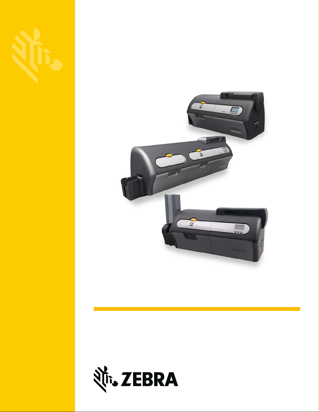
A YMCKO ribbon has successive panels as follows:
Color Technology Function / Usage
Yellow (“Y”) Dye Sublimation
Magenta (“M”) Dye Sublimation
Cyan (“C”) Dye Sublimation
Black Resin (“K”) Thermal Transfer
Overlay (O) - -
Thermal Transfer
Printing Process
(YMCKO)
Pattern
Repeats)
Overlay
(O)
Black
(K)
Resin
Cyan
(C)
Dye
Full-Color Printing and Dye
Sublimation Black Printing
Full-Color Printing and Dye
Sublimation Black Printing
Full-Color Printing and Dye
Sublimation Black Printing
K Resin Black Printing (for the
front of the card)
Dye Sublimation
Printing Process
Magenta
(M)
Dye
Yellow
(Y)
Dye
Ribbon movement from supply spool
Other ribbons are available for the printer; see the Supplies List on the Driver and
Documentation CD that came with the printer, or visit the Zebra Card Printer Solutions
website at zebra.com/supplies.
6 ZXP Series 7 Card Printer Service Manual P1036102-007
Page 13
Theory of Operation
Printing Technologies and Ribbons
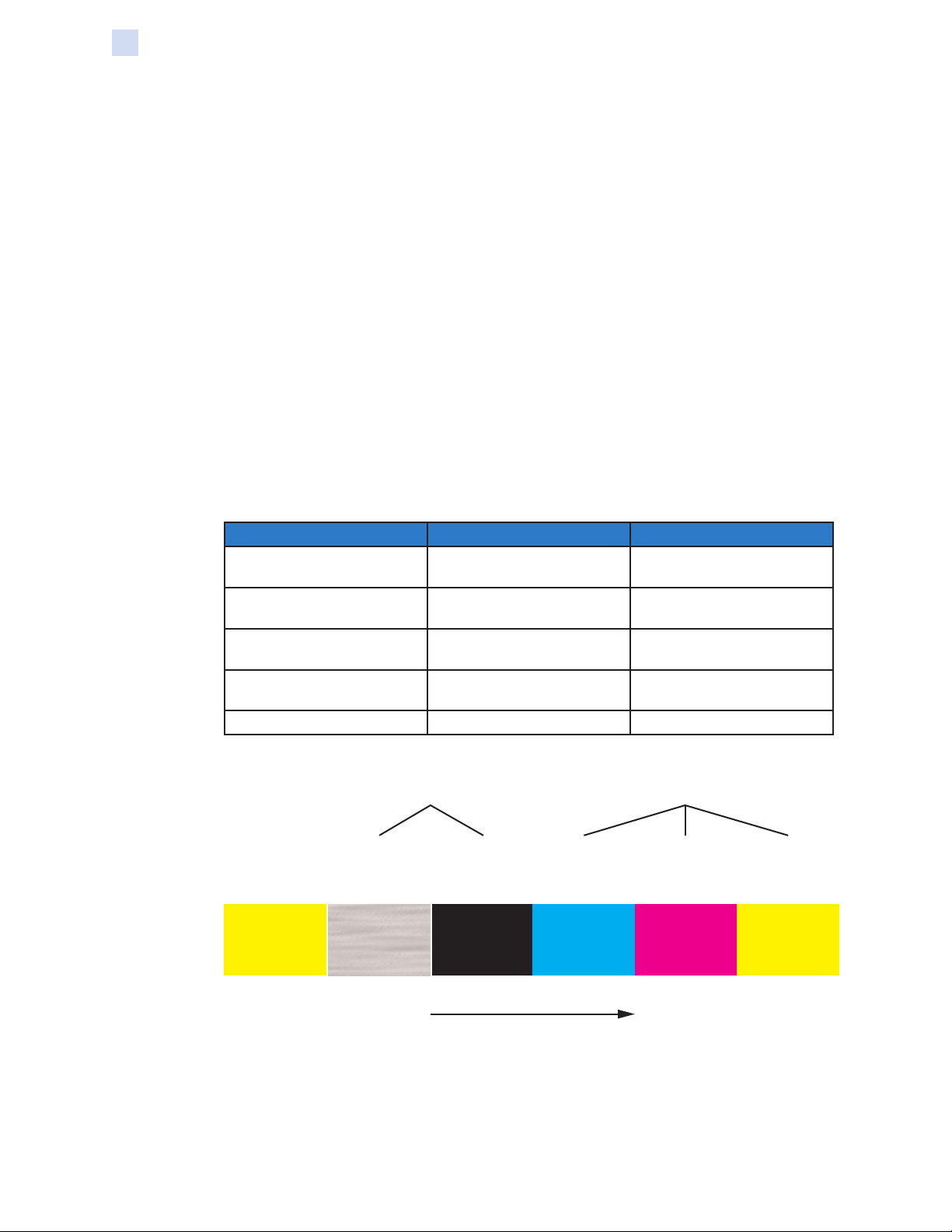
The ribbon synchronizes to it’s “starting” position whenever the Print Cover is opened
and then closed. For a YMCKO ribbon, the starting position is with the leading edge of
a Yellow Panel at the printhead location.
The figure below shows how the YMCKO ribbon and card move relative to each other
during printing.
Printhead in fixed position1. Ribbon move yellowpanel into
position at printhead.
2. Card is fed to printing position
under the printhead.
3. Card and ribbon move together as
yellow panel is printed.
4. Card and ribbon stop at the end
of the yellow panel.
5. Ribbon remains stationary as card
is moved back to printing position.
6. Card and ribbon move together as
magenta panel is printed.
In addition, the driver software allows the user to specify which ribbon panels are
printed on either side of the card.
P1036102-007 ZXP Series 7 Card Printer Service Manual 7
Page 14
Theory of Operation
Printing Technologies and Ribbons
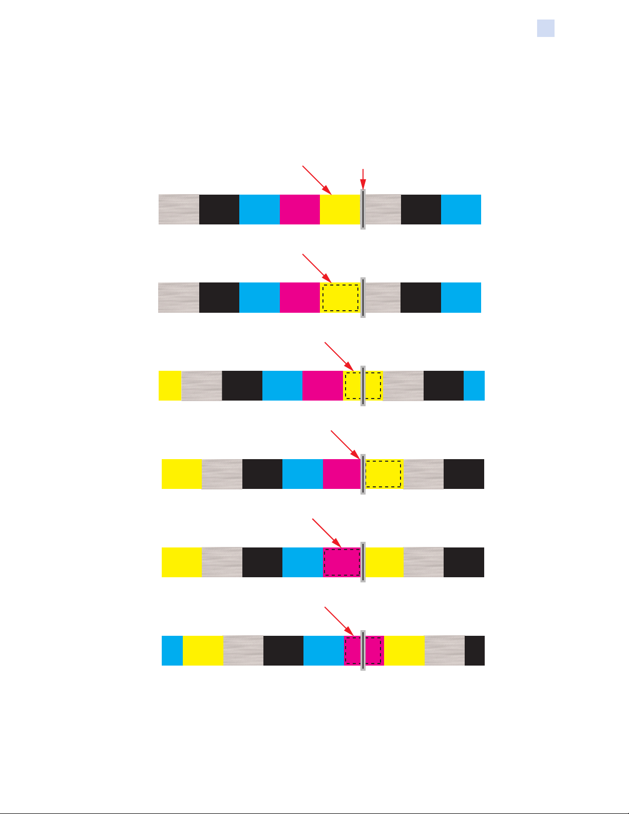
Dye Sublimation Printing
In Dye Sublimation Printing, each printhead heating element is applied voltage at one
of a number of pulse widths.
A wider pulse results in the element getting hotter, which converts more of the dye (at
that pixel location) to a gas and diuses it into the surface of the card (a wider pulse
gives more intense color at that pixel).
This is repeated for each of the dye panels (i.e., Yellow, Magenta, and Cyan), to result
in full-color images.
Ribbon Carrier
Layer
Ribbon Ink
Layer
Card
Printhead
Gaseous dye is
absorbed by the card
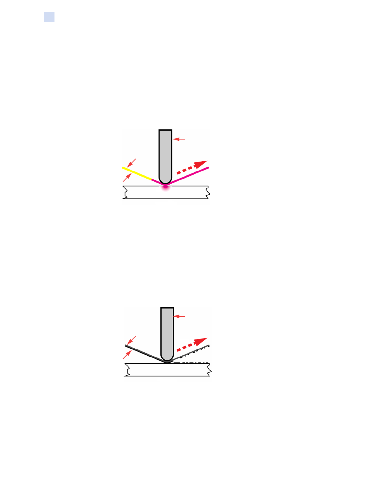
Thermal Transfer Printing
In Thermal Transfer Printing, voltage is either applied or not applied to each printhead
printing element. If voltage is applied, the ink at that location is transferred to the
surface of the card.
Each pixel is either printed (i.e., the ink is transferred to the card) or not; there are no
intermediate levels.
Thermal Transfer printing with a black (K) resin panel is used for printing bar codes,
since contrast between the light and dark areas is the highest and the edges are the
sharpest.
Ribbon Carrier
Layer
Ribbon Ink
Layer
Card
Printhead
Ink is transferred to the
surface of the card
8 ZXP Series 7 Card Printer Service Manual P1036102-007
Page 15
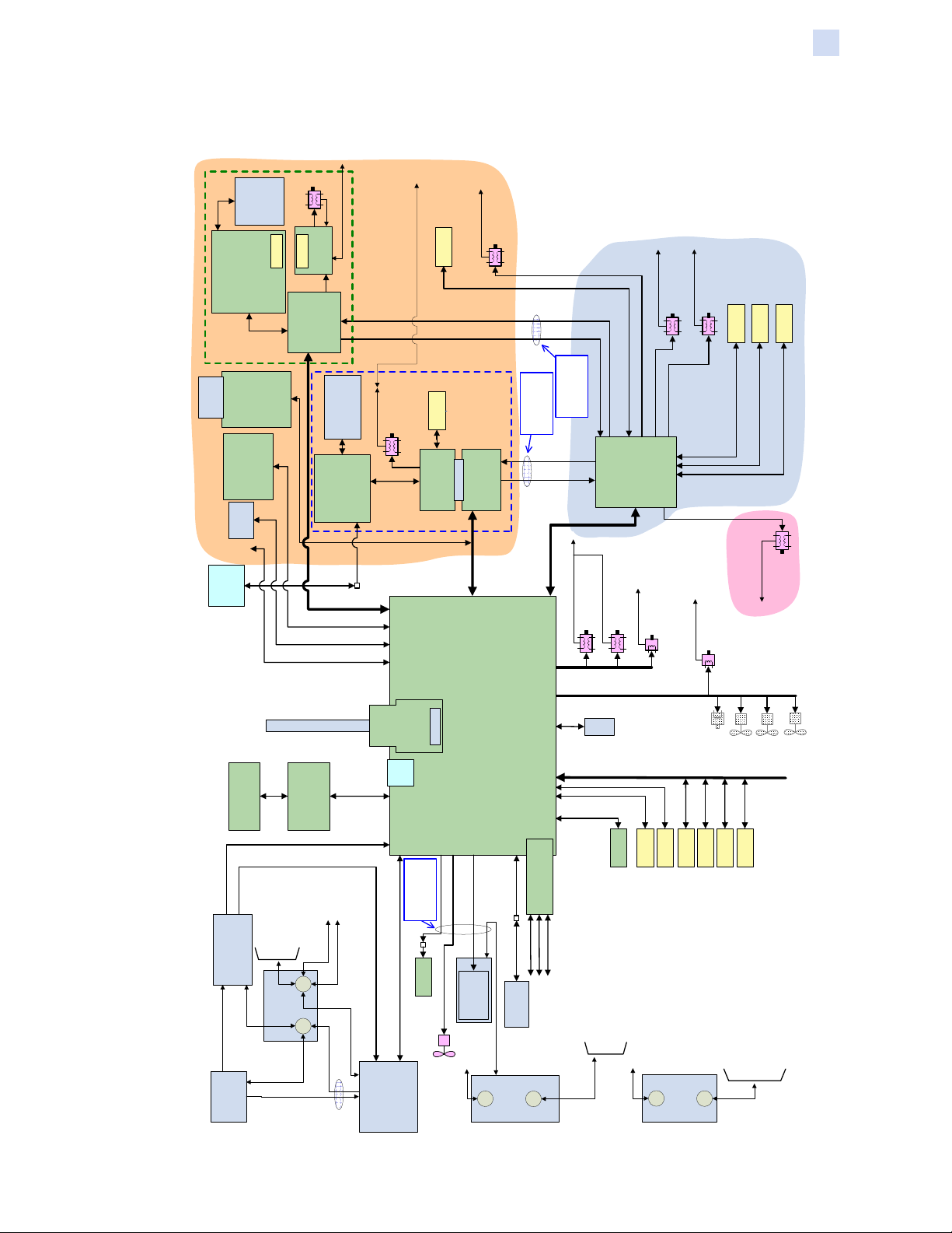
System-Level Electronics
)
MAG_ISO(P1029189
Mag Head
MTR_OPMG
(P1039207)
LED
Detector
(PCBA_MAG_
SEN_OPMG
P1038451-01)
Mag Module PCBA
(PCBA_MAG_MOD_IF
(P1031857)
Mag PCBA
CA_MAG_MOD_IF
Options Module
(P1027378-02)
PCBA_FELICA_CAR
or
or
UHF Mod
Felica Mod
OPTIONS MODULE
DB9 for
External
(P1027378-01)
PCBA_UHF_CAR
SmartCard
for User Auth)
Authentication
(Contact SmartCard
Reader
Barcode
(BARCD)
USB
Host
Ports
Station
Contact
MAG
MOD_DET,
P1038478-01)
CA_MTR_OPMG-MOD_GND (P1033288)
P1038415-01)
(PCBA_OPMAG,
(P1029200)
(if required)
MTR_OPCM
(P1033220)
(PCBA_CPLR_SC)
SmartCard Coupler
CA_MTR_OPCM_GND
PCBA
(SC_MOD,
P1006651-01)
806882-001) or
Ext Contact Stn i/f
SmartCard Module
(PCBA_EXTCNT_IF,
CA_SC_MOD
CA_SC_MOD
(P1029151) or
CA_EXT
(P1043050)
(P1042978)
CA_EXT_DB9
CA_OPMAG (P1026484)
CA_USRAUTH
CA_BARCD
CA_UCONN
Theory of Operation
System-Level Electronics
SEN_OPCD
(300238G-002)
Gap
Sensor
CA_MTR_OPCM-MOD_GND (P1033283)
OPMAG_PD_N
Gap
Sensor
SEN_OPCM
SmartCard
Module PCBA
P1028126-01)
(PCBA_SC_MOD,
_EXT
(P1042729)
(P1044093)
MTR_OPCD
CA_MTR_OPCD_GND
(P1042321)
MTR_FLCD
CA_MTR_FLCD_GND
SEN_FLCD
MTR_FLRO
(P1026465-002)
CA_MTR_FLRO_GND
Gap
SEN_FDOP
(P1030185)
SEN_FLRO
(300364-006)
(300364-007)
Gap
Gap
Sensor
Sensor
Sensor
SMARTCARD
(P1026478)
CA_FLOPMAG
are combined into
These connections
(P1026476)
(P1029126)
Connectors
P1028104-01)
(PCBA_OPSC,
Options Module
SmartCard PCBA
CA_OPSC_RF
CA_OPSC
(P1027859)
CA_FLOPSC
are combined into
These connections
CA_FLIP_PWR (P1026479)
CA_FLIP_CTL (P1026480)
MTR_OPMG_CTL
MTR_OPCM_CTL
OPSC_PD_N
(PCBA_FLIP,
P1021234-01)
Flipper Board PCBA
FLIPPER
FEEDER
CA_MTR_FEED_GND
(P1041216)
MTR_FEED
CA_MTRS_ENG_GND
MTR_MAIN (P1009157-001)
MTR_CAM (P1009302)
MTR_RIBS (P1020449)
CA_MTR_RIBS_GND
CA_MTR_MCB (P1014939)
MTR_RIBT (P1020406)
CA_MTR_RIBT_GND
(Individual motor cables)
WiFi Antenna (ANT, P1005199)
(300844-001)
CA_CPLR_MA
(PCBA_MAB,
P1008230-02)
(PCBA_CPLR_MA,
Media Auth Coupler
(P1029730)
CA_MTRS_ENG_GND
P1008702)
(PWR_SUP,
200W Power Supply
(P1014040)
CA_SUP_GND
CA_ACPWR (P1013793)
EMI Filter
P1035695)
(PWR_SW,
AC Switch &
404870-003P)
Media Auth PCBA
DC output CN2 is term block)
DC output CN2 is conn)
(P1029884)
(P1022300)
CA_MTR_RIBT_GND
CA_BRUSH_EXIT
CA_ENGINE_GND
CA_OPTIONS_GND
P1010902)
(GND_MCB,
Ground Plate
PE
(P1013891)
CA_SW_GND
CA_LAM_DC (P1030139)
(P1041281)
CA_LAM_GND
(Osprey P/N: P1004275)
CA_LAM_AC (P1029986)
or
Board
Ethernet
(P1025470)
CA_MAB
(Osprey P/N: 300827-001:
CA_DCPWR (P1030122:
(Osprey P/N: P1004276)
CA_LAM_CTL (P1030001)
Laminator
FSI Conn
P1006890-02
P1006890-03)
(PCBA_ENET,
Port
USB
Periph
CA_PH
are combined into
These connections
Tri-Color
SEN_RIBA
(Osprey P/N: P1004277)
(LAM)
(PCBA_MCB,
P1047494-01)
Main Controller Board PCBA
P1043417-01)
(PCBA_DIAG_IF,
(P1037316)
Emitter
Print Head
(404790-003P)
(P1044307)
FAN_PH (blower)
CA_ENGINE_GND (P1032223)
(P1032163)
IP/EP Diagnostic Board
CA_OCP_RECEPT
JTAG
(P1032161)
CA_IP_DEBUG
CA_EP_DEBUG
CA_OCP_PLUG
(PH,
P1040725)
(OCP,
OCP Assy
P1027292)
PH_GND
P1030086)
(GND_ENG,
Ground Plate
Thermistor
(P1051848)
CA_THERM
Gap
(P1037399)
CA_SEN_RIBB
CA_BRUSH_CLSOUTS (P1029745-001)
Gap
Sensor
Sensor
Detector
Tri-Color
SEN_EXIT
SEN_RIBB
SEN_TENC
(300364-003)
(405030-003B)
CA_BRUSH_FEED_RGHT (P1029727)
CA_MTR_RIBS_GND (P1029883-001)
CA_BRUSH_FEED_LEFT (P1029728)
CA_MTR_FEED_GND (P1029744-001)
CA_OPTIONS_GND
(300364-010)
(P1032220)
MTR_SP
CA_SEN_MCB (P1014941)
Gap
Sensor
SEN_SENC
(300364-002)
P1029901)
Ground Plate
(GND_FLOP,
FAN_PWR
Gap
Gap
Gap
Sensor
Sensor
SEN_CAM
SEN_CSYN
SEN_DOOP
(300364-009)
(300364-008)
CA_FLIP_SHFT_GND (P1029747-001)
CA_MTR_FLCD_GND (P1032300)
CA_MTR_OPCD_GND (P1032300)
FAN_SP2
FAN_SP1
Sensor
(300238G-004)
CA_MTR_FLRO_GND (P1032281)
CA_BRUSH_ATM (P1029833)
CA_BRUSH_FLIP (P1032340)
CA_MTR_OPMG-MOD_GND (P1033288)
CA_MTR_OPCM-MOD_GND (P1033283)
P1036102-007 ZXP Series 7 Card Printer Service Manual 9
Page 16
Theory of Operation
System-Level Electronics
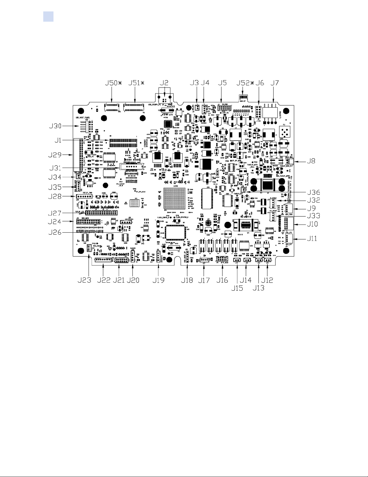
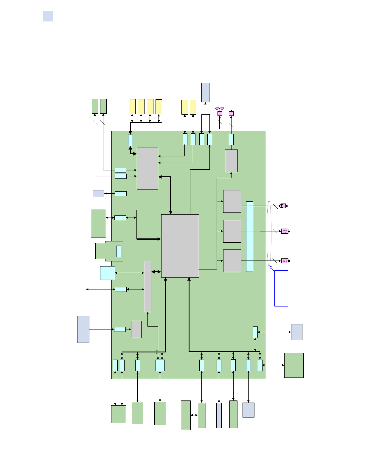
Main PCBA (CPU)
PCBA Layout
* J50, J51, and J52 are on the bottom side of the Main PCBA
10 ZXP Series 7 Card Printer Service Manual P1036102-007
Page 17

Theory of Operation
System-Level Electronics
PCBA Connections
Connector PCBA ID Functional Description
J1 ETHERNET INTERFACE Ethernet Daughterboard
J2 USB_PERIPH_PC USB peripheral interface from host PC
J3 SEN_RIBA Ribbon tri-color sensor (detector)
J4 SEN_RIBB Ribbon tri-color sensor (emitter)
J5 PH_PWR Power to printhead
J6 JTAG RESERVED
J7 DCPWR DC power input to board
J8 MTR_RIBT Ribbon take-up motor
J9 SEN_TENC Ribbon take-up encoder wheel sensor
J10 LAM_CTL Control signals to Laminator or Hopper
J11 SEN_EXIT Exit sensor
J12 -- RESERVED
J13 -- RESERVED
J14 -- RESERVED
J15 -- RESERVED
J16 MTR_MCB Stepper motors driven by MCB
J17 -- RESERVED
J18 USB_HOST_SP RESERVED
J19 USRAUTH User Authentication
J20 BARCD Barcode Reader
J21 OCP Operator Control Panel
J22 MAB Media Authentication Board
J23 SEN_CAM RESERVED
J24 SEN_MCB Various sensors
J25 N/A N/A
J26 UHF/FELICA RESERVED
J27 FDFLIP_CTL Control signals to Flipper Board
J28 FDFLIP_PWR Power to Flipper Board
J29 PH_DATA Printhead Data
J30 USB_HOST_PANEL USB Dual Host cable
J31 -- RESERVED
J32 IP_DEBUG RESERVED
J33 EP_DEBUG RESERVED
J34 SEN_RIBA_NEW Ribbon tri-color sensor (emitter)
J35 SEN_RIBB_NEW Ribbon tri-color sensor (detector)
J36 THERM RESERVED
J50* OPSC SmartCard option board
J51* OPMAG Mag option board
J52* DIAG I/F Diagnostic test
* J50, J51, and 52 are on the bottom side of the Main PCBA
P1036102-007 ZXP Series 7 Card Printer Service Manual 11
Page 18
Theory of Operation
MTR_
System-Level Electronics
PCBA Block Diagram
Most of the circuitry in the printer is on the Main PCBA. Since the Main PCBA is not a
serviceable unit, there is no component level circuit analysis.
SEN_RIBB
SEN_RIBA
Emitter
Detector
Tri-Color
Tri-Color
2
5
Thermistor
CA_THERM
P1043417-01)
(PCBA_DIAG_IF,
IP/EP Diagnostic Board
Board
Ethernet
Daughter
(PCBA_ENET)
J2
Main PCBA
CA_UCONN
SEN_SENC
Gap
J24
J35
J34
J36
J52
J1
J30
SEN_CSYN
SEN_CAM
Gap
Sensor
USB_PERIPH_PC
SEN_DOOP
Gap
Gap
Sensor
Sensor
Sensor
CA_SEN_MCB
Sensor Interface
A2D for analog inputs)
(tri-color sensor circuit,
74HC14's for digital sensor inputs,
Debug Interfaces
USB Interfaces
USB Logic
USB_HOST_PANEL
Remote Board Interfaces
SEN_TENC
Gap
Sensor
J9
MCB Sensor Interfaces
Print Head Interface
CPU Subsystem
(FPGA, DDR, Flash,
clock buffering, I2C mux, etc.)
External Module Interfaces
(PH)
Print Head
SEN_EXIT
FAN_PH
Gap
Sensor
CA_PH
(PH_DATA)
(PH_PWR)
J5
J11
J29
MTR_RIBT
2
2
J8
BEMF Circuit
A3966
A4983
J16
MCB Motor Driver Interfaces
A3979
2
4
4
connects to J16 here.
a C/A (CA_MTR_MCB) that
These motors each plug into
MTR_RIBS
MTR_CAM
MAIN
J7
(PWR_SUP)
200W Power Supply
CA_DCPWR
J28
CA_FDFLIP_PWR
Flipper
Module
Power
DC-DC
Conversion
J21
J10
J51
J27
CA_OPMAG
CA_FDFLIP_CTL
PCBA
Mag PCBA
(PCBA_FLIP)
(PCBA_OPMAG)
CA_OPSC
SmartCard PCBA
J50
(PCBA_OPSC)
Media Auth
J22
CA_OCP
CA_LAM_CTL
CA_MAB
CA_CPLR_MAB
(PCBA_MAB)
Coupler PCBA
Media Auth PCBA
(PCBA_CPLR_MAB)
(PCBA_OCP)
Laminator (LAM)
OCP Support PCBA
J26
J19
J20
CA_BARCD
Reader
Barcode
(BARCD)
CA_UHF-FELICA
UHF/Felica
CA_USRAUTH
SmartCard
for User Auth)
Authentication
(PCBA_USRAUTH)
(Contact SmartCard
12 ZXP Series 7 Card Printer Service Manual P1036102-007
Page 19
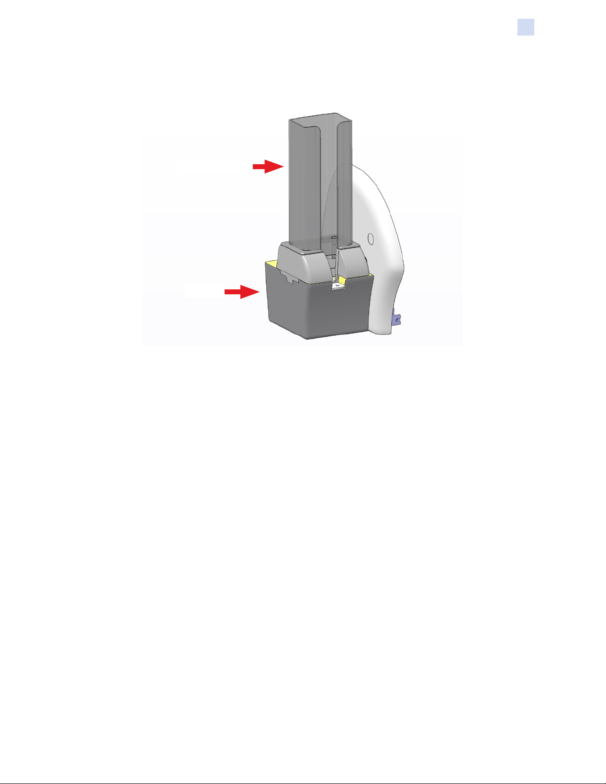
High-Capacity Output Hopper
Hopper Cassette
Stacker
Theory of Operation
High-Capacity Output Hopper
Hopper Cassette
• Easily removable from, and replaceable back onto, stacker base (full, partial, or
empty of cards).
• Equipped with a locking mechanism for capturing and holding stacked cards.
• Open front slot to allow for manual removal of cards (from 1 to 250 cards) without
removing stacker from base.
• With the hopper cassette removed, cards can be removed from top, not from
bottom as locking mechanism is not reversible.
Stacker
The high-capacity output hopper receives and automatically stacks cards in the order
they were printed—top face up—with the first card printed at the top of the stack, and
the last card printed at the bottom of the stack.
The high capacity output hopper runs independently of the printer and responds only
to the card present sensor at the entrance to the hopper. With the cassette in place,
the hopper will stack cards continuously based on print job (including overfilling over
the top of the cassette). With the cassette removed, the elevator will not actuate,
but the printer will continue to print and printed cards will accumulate on the stacker
base—up to 9 cards (30 mil) will accumulate before being pushed o the stacker base.
P1036102-007 ZXP Series 7 Card Printer Service Manual 13
Page 20

14 Hopper Cassette
Page 21

Introduction
The table on the next page oers causes and solutions to symptoms related to
improper operation. Check the table on the following pages when experiencing any
loss of operation or print quality.
3
Troubleshooting
For additional information on troubleshooting and advanced operations, you can
access an extensive Knowledge Base at km.zebra.com.
P1036102-007 ZXP Series 7 Card Printer Service Manual 15
Page 22

Troubleshooting
OCP Error Messages
OCP Error Messages
Important • If the Possible Solution does not solve your problem, contact Zebra
Technical Support.
CODE MESSAGE POSSIBLE CAUSE POSSIBLE SOLUTION
5
6 DIAGNOSTIC ERROR
7
8
3001 PRINTER OFFLINE
4003 CARD JAM Card is jammed in the Printer. Clear the card path.
4014 CARD FEED ERROR
FIRMWARE UPGRADE
ERROR
FIRMWARE UPGRADE
ERROR
CRITICAL ERROR
SHUTTING DOWN
Firmware upgrade
incompatibility.
Error encountered in
Diagnostic Mode.
Firmware upgrade failed.
Major malfunction encountered. Contact Zebra Technical Support.
Status toggled (ofine/online)
via the OCP Advanced Settings
Menu.
Card is jammed in Feeder
Cartridge.
Verify the version, and retry installing
the rmware.
Power cycle the printer, and retry.
Verify the version, and retry installing
the rmware.
Change status to ONLINE via the
OCP Advanced Settings Menu.
1. Clear card jam in Feeder
Cartridge, and re-seat Feeder
Cartridge.
2. Ensure that cards are not stuck
together and that they are the
correct thickness (10 to 50 mil).
1. Load cards in the Feeder
Printer is out of cards.
Card was not fed into the
4015 CARD NOT INSERTED
5001 OUT OF RIBBON Print ribbon has run out. Load a new roll of print ribbon.
5002 INVALID RIBBON
5003 RIBBON JAM Print ribbon is jammed.
5004 RIBBON MOTION ERROR
5006 RIBBON BEMF ERROR
5007
RIBBON COLOR DETECT
ERROR
Manual Feed Slot within
30-second period.
Print ribbon does not match the
printer.
Print ribbon is stretched. Recalibrate ribbon torque.
Print ribbon is broken.
Problem with the Back EMF
(BEMF) of the ribbon motors.
Print ribbon is not installed
correctly.
Cartridge.
2. Re-seat the Feeder Cartridge.
Retry and feed a card into the Manual
Feed Slot, or cancel the operation.
Verify the part number of the print
ribbon is correct on OCP.
1. Check the print ribbon.
2. Reinstall the print ribbon.
3. Repair the break in the print ribbon
and reinstall.
Tape the broken ends of the ribbon
together, roll the ribbon around the
take-up spool, place the ribbon back
in the printer, and power cycle the
printer.
Contact Zebra Technical Support.
Reinstall the print ribbon. If reinstalling
the ribbon does not solve the problem,
contact Zebra Technical Support.
16 ZXP Series 7 Card Printer Service Manual P1036102-007
Page 23

Troubleshooting
OCP Error Messages
CODE MESSAGE POSSIBLE CAUSE POSSIBLE SOLUTION
1. Verify the part number of the print
ribbon is correct on OCP.
2. Power cycle the printer, and retry.
Power cycle the printer, and retry.
Power cycle the printer, and retry.
Power cycle the printer, and retry.
Power cycle the printer, and retry.
Power cycle the printer, and retry.
Power cycle the printer, and retry.
Power cycle the printer, and retry.
1. Clear card jam in Feeder
Cartridge, and re-seat Feeder
Cartridge.
2. Ensure that cards are not stuck
together and that they are the
correct thickness (10 to 50 mil).
1. Load cards in the Feeder
Cartridge.
2. Re-seat the Feeder Cartridge.
Check printhead cable connection,
reconnect if loose or disconnected.
Remove the card from the exit area.
Move the printer to a cooler
environment, or cool the area of
operation.
Move the printer to a warmer
environment, or warm the area of
operation.
This warning will be cleared when the
printer cover is closed.
Power cycle the printer, and retry.
Power cycle the printer, and retry.
Power cycle the printer, and retry.
5008 INVALID RIBBON
6001 6008
6009 FLASH ERASE ERROR
6010
6011
6012
6013 INVALID FW S-RECORD
6015 6025
7001 CARD FEED ERROR
7002 CARD CLEAN ERROR
7003
7004 CARD EJECT ERROR
7005 PRINTHEAD TOO HOT
7006 PRINTHEAD TOO COLD
7008 PRINT COVER OPEN
7010
7013
7014
7015 MAG MOTION ERROR
GENERAL MEMORY
ERROR
FLASH ERASE VERIFY
ERROR
FLASH PROGRAM
ERROR
FLASH PROGRAM
VERIFY ERROR
GENERAL MEMORY
ERROR
PRINTHEAD CABLE
ERROR
PRINTHEAD MOTION
ERROR
MOTOR VOLTAGE
ERROR
SCRIPT PROCESSING
ERROR
Print ribbon does not match the
printer.
There is a problem when
accessing general memory.
There is a problem when
accessing ash memory.
There is a problem when
accessing ash memory.
There is a problem when
accessing ash memory.
There is a problem when
accessing ash memory.
There is a problem when
accessing ash memory.
There is a problem when
accessing general memory.
Card is jammed in Feeder
Cartridge.
The printer is out of cards.
Printhead cable loose or
disconnected.
Card from previous job is stuck
in the exit area.
Environmental issue -- the
ambient temperature is too hot.
Environmental issue -- the
ambient temperature is too
cold.
This warning will be displayed if
the cover protecting the Printer
Module is opened.
Printhead did not move
to proper position during
initialization.
Incorrect voltage detected at
one or several motors in the
unit.
Internal logic error. Power cycle the printer, and retry.
This is a magnetic encoding
retrace error.
P1036102-007 ZXP Series 7 Card Printer Service Manual 17
Page 24

Troubleshooting
OCP Error Messages
CODE MESSAGE POSSIBLE CAUSE POSSIBLE SOLUTION
1. Ensure that you are using the
correct card type.
7018 SMARTCARD ERROR
7019
7020 SCRIPT SEND ERROR Internal logic error. Power cycle the printer, and retry.
7023
7024 OPTIONS CARD JAM
7026 FLIPPER CARD JAM Card is jammed in the Flipper. Clear the card path.
7028 OPTIONS COVER OPEN
7029
7032 SINGLE CARD FEED JAM
7033 FLIPPER BOARD ERROR The Flipper has failed. Contact Zebra Technical Support.
7034
7035 OPTIONS CARD JAM
7036 7039
9001 MAG READ ERROR
SCRIPT CONTENT
ERROR
SMART CARD CAM INIT
ERROR
FLIPPER ROTATION
ERROR
REJECT BIN FULL
REMOVE CARDS
PRINT CARD JAM
• Encoding error.
• Faulty card.
Internal logic error. Power cycle the printer, and retry.
Mechanical positioning issue. Power cycle the printer, and retry.
Card is jammed in the Options
Module, Feeder Cartridge.
This warning will be displayed
if the cover protecting the
Options Module is opened.
The Flipper has failed. Contact Zebra Technical Support.
Card is jammed in the Options
Module, Single Card Feed Slot.
The Reject Bin is full.
Card is jammed in the Options
Module, Magnetic Encoder.
Card is jammed in Printer
Module.
• Encoding error.
• Defective magnetic stripe.
2. Check that the cards are loaded in
the correct orientation.
3. Ensure that the data conforms to
ISO Specications.
4. Retry writing and reading.
Clear the card path.
This warning will be cleared when the
options cover is closed.
Clear the card path.
Remove the cards from the bin, and
reset the reject bin card count to 0
via the OCP (Main Menu > Advanced
Settings > Clear Reject Bin).
Clear the card path.
Clear the card path.
1. Ensure that you are using the
correct card type.
2. Check that the cards are loaded
with the magnetic stripe in the
correct orientation.
3. Ensure that the cards are setup correctly in the printer driver
(coercivity setting).
4. Ensure that the data conforms to
ISO Specications.
5. Retry reading.
18 ZXP Series 7 Card Printer Service Manual P1036102-007
Page 25

Troubleshooting
OCP Error Messages
CODE MESSAGE POSSIBLE CAUSE POSSIBLE SOLUTION
1. Ensure that you are using the
correct card type.
2. Check that the cards are loaded
with the magnetic stripe in the
9002 MAG WRITE ERROR
9004 NO MAG STRIPE Magnetic stripe not detected.
10001 CONTACT READ ERROR
10002
11001
11002
15001 MISSING MAB
15002
17001 LAMINATOR MISSING
17002
CONTACT WRITE
ERROR
CONTACTLESS READ
ERROR
CONTACTLESS WRITE
ERROR
MAB FIRMWARE
MISSING
LAMINATOR FAILED
INITIALIZATION
• Encoding error.
• Defective magnetic stripe.
• Wrong card type is in use.
• Card orientation in the
Feeder Cartridge is wrong.
• Smart Card Options Module
is incorrectly installed.
• Wrong card type is in use.
• Card orientation in the
Feeder Cartridge is wrong.
• Wrong card type is in use.
• Smart Card Options Module
is incorrectly installed.
• Wrong card type is in use.
• Smart Card Options Module
is incorrectly installed.
An error occurred when
reading the RFID Tag by the
MAB (Media Authentication
Board).
MAB (Media Authentication
Board) Firmware is missing.
Laminator was detected by
the printer, but was unable to
communicate to it.
correct orientation.
3. Ensure that the cards are setup correctly in the printer driver
(coercivity setting).
4. Ensure that the data conforms to
ISO Specications.
5. Retry writing.
1. Ensure that you are using the
correct card type.
2. Check that the cards are loaded
with the magnetic stripe in the
correct orientation.
1. Ensure that you are using the
correct card type.
2. Check that the cards are loaded
with the chip in the correct
orientation.
3. Re-seat the Smart Card Options
Module.
1. Ensure that you are using the
correct card type.
2. Check that the cards are loaded
with the chip in the correct
orientation.
3. Re-seat the Smart Card Options
Module.
1. Ensure that you are using the
correct card type.
2. Re-seat the Smart Card Options
Module.
1. Ensure that you are using the
correct card type.
2. Re-seat the Smart Card Options
Module.
1. Check print ribbon orientation.
2. Verify part number of the print
ribbon.
3. Power cycle the printer, and retry.
Install the rmware.
Contact Zebra Technical Support.
P1036102-007 ZXP Series 7 Card Printer Service Manual 19
Page 26

Troubleshooting
OCP Error Messages
CODE MESSAGE POSSIBLE CAUSE POSSIBLE SOLUTION
17003
17004
17005
17006
17007
17008
17009
17010
17011
17012
LAMINATOR UNKNOWN
ERROR
MISSING LAMINATOR
MAB
TOP LAMINATE FEED
FAIL
BOTTOM LAMINATE
FEED FAIL
TOP LAMINATE
REGISTRATION ERROR
LAMINATOR CARD FEED
FAIL
LAMINATOR EARLY
CARD JAM
LAMINATOR MIDDLE
CARD JAM
LAMINATOR LATE CARD
JAM
LAMINATOR POLL
TIMEOUT
An unknown error has occurred
– this is an indication of a FW
problem and should not occur.
An error occurred when
trying to communicate to
the Laminator MAB (Media
Authentication Board).
• Top laminate cartridge is not
installed properly.
• Cartridge is not removed
when that side of the card is
not being laminated.
• A mis-cut piece of laminate
(rare) is obscuring the media
sensor.
• Bottom laminate cartridge is
not installed properly.
• Cartridge is not removed
when that side of the card is
not being laminated.
• Improperly prepared
registered laminate.
• Media misfeed.
• Patch length improperly set.
• Unexpected end of laminate
roll detected.
Printer has not fed the card
far enough into laminator
mechanism for infeed rollers to
grab it.
Card did not make it to the
staging rollers.
Card and laminate have
jammed inside heater
assembly, often due to mispositioned laminate patch
sticking to heated rollers.
Card did not unblock the exit
sensor in the specied time.
The laminator expects the
printer to periodically send
commands to it within a
specied time period. If it
fails to do so, it assumes that
something is wrong with the
communication link or that the
printer is down. This error may
occur if the printer-to-laminator
communications is having
intermittent problems.
1. Press RETRY on the OCP.
2. Contact Zebra Technical Support.
1. Power cycle the printer, and retry.
2. Contact Zebra Technical Support.
1. Remove, reposition, and re-install
the top laminate cartridge.
2. Remove the top laminate
cartridge.
3. Remove the mis-cut piece of
laminate.
1. Remove, reposition, and re-install
the bottom laminate cartridge.
2. Remove the bottom laminate
cartridge.
Remove and re-cut laminate in the
center of the index notch, re-install,
and retry.
Open the Laminator and printer doors
to check for jammed/stuck cards.
Remove the card and/or laminate
that is stuck in the laminator staging/
cutting area.
Remove the oven, and inspect for
stuck cards.
1. Check for card jam in the exit area.
2. Assure that the sliding exit door is
not partially blocking the exit path.
Power cycle the printer, and retry.
20 ZXP Series 7 Card Printer Service Manual P1036102-007
Page 27

Troubleshooting
OCP Error Messages
CODE MESSAGE POSSIBLE CAUSE POSSIBLE SOLUTION
Top heater did not turn on
after being instructed to
do so. When the heater
is enabled, the controller
17013
17014
17015
17016
17017
17118
17019
17020
17021
17022
17023 LAMINATOR FAN FAIL
LAMINATOR TOP
HEATER FAIL
LAMINATOR BOTTOM
HEATER FAIL
LAMINATOR TOP
TEMPERATURE HIGH
LAMINATOR BOTTOM
TEMPERATURE HIGH
LAMINATOR TOP
CUTTER STALL
LAMINATOR BOTTOM
CUTTER STALL
LAMINATOR TOP
CUTTER FAIL
LAMINATOR BOTTOM
CUTTER FAIL
LAMINATOR TOP TEMP
SENSOR FAIL
LAMINATOR BOTTOM
TEMP SENSOR FAIL
will wait a certain specied
amount of time for it to attain
the set target temperature. If
the heater fails to reach the
target in the specied time, the
TopHeaterFail fault will be set.
Bottom heater did not turn
on after being instructed
to do so. When the heater
is enabled, the controller
will wait a certain specied
amount of time for it to attain
the set target temperature. If
the heater fails to reach the
target in the specied time, the
BotHeaterFail fault will be set.
If the top roller temperature
ever exceeds a xed
temperature threshold, the over
temp error occurs.
If the bottom roller temperature
ever exceeds a xed
temperature threshold, the over
temp error occurs.
Top cutter blade is obstructed,
or top cutter mechanism is
damaged.
Bottom cutter blade is
obstructed, or bottom cutter
mechanism is damaged.
Top cutter has failed.
Bottom cutter has failed.
The top temperature
(thermopile) sensor has failed.
The bottom temperature
(thermopile) sensor has failed.
This should only happen if one
or both cooling fans fail or the
cooling vents near the heated
roller assembly are blocked or
the fan(s) have failed.
Replace the top halogen bulb.
Replace the bottom halogen bulb.
1. Power cycle the printer, and retry.
2. If this error persists, contact Tech
Support.
1. Power cycle the printer, and retry.
2. If this error persists, contact Tech
Support.
If this error persists, contact Tech
Support.
If this error persists, contact Tech
Support.
If this error persists, contact Tech
Support.
If this error persists, contact Tech
Support.
If this error persists, contact Tech
Support.
If this error persists, contact Tech
Support.
Check for blocked vents.
P1036102-007 ZXP Series 7 Card Printer Service Manual 21
Page 28

Troubleshooting
OCP Error Messages
CODE MESSAGE POSSIBLE CAUSE POSSIBLE SOLUTION
The parameters stored in
EEPROM have been reset
to their default values. This
will not normally happen, but
17024
17026
17027 TOP LAMINATE OUT The top laminate has run out. Load new roll of laminate.
17028 BOTTOM LAMINATE OUT
17029 INVALID TOP LAMINATE
17030
17031
17032 REMOVE TOP LAMINATE
17033
17034
17038
17040
17041
LAMINATOR EEPROM
DEFAULT
TOP AND BOTTOM
LAMINATES OUT
INVALID BOTTOM
LAMINATE
BOTTOM LAMINATE
REGISTRATION ERROR
REMOVE BOTTOM
LAMINATE
REMOVE TOP AND
BOTTOM LAMINATES
LAMINATOR COVER
OPEN
LAMINATOR
INITIALIZING
LAMINATOR FIRMWARE
MISSING
could be seen with certain
FW upgrades when new
parameters have been added
by Engineering. It could also
indicate a problem with the
Laminator’s EEPROM.
The top and bottom laminates
have run out.
The bottom laminate has run
out.
Laminate does not match the
printer.
Laminate does not match the
type allowed in the laminator
or top and/or bottom has been
swapped.
• Improperly prepared
registered laminate.
• Media misfeed.
• Patch length improperly set.
• Unexpected end of laminate
roll detected.
Top laminate is installed when
the driver lamination mode
“Bottom” is selected.
Bottom laminate is installed
when the driver lamination
mode “Top” is selected.
Top and bottom laminates
are installed when the driver
lamination mode “Pass
through” is selected.
This warning will be displayed
if the cover protecting the
laminator is opened.
This warning will be displayed
after the laminator door is
closed and laminate spools are
re-read/detected.
Laminator Controller Board
(LCB) Firmware is missing.
1. Press RETRY on the OCP when
this error occurs.
2. Power cycle the printer, and retry.
Load new rolls of laminate.
Load new roll of laminate.
1. Verify the part number of the
laminate is correct on OCP.
2. Power cycle the printer, and retry.
1. Verify that the top and bottom
laminate cassettes are installed in
the correct locations.
2. Verify the part number of the
laminate is correct on OCP.
3. Power cycle the printer, and retry.
Remove and recut laminate in the
center of the index notch, re-install,
and retry.
Remove the top laminate cassette.
Remove the bottom laminate
cassette.
Remove both laminate cassettes.
This warning will be cleared when the
laminator cover is closed.
No action needed
Install the rmware.
22 ZXP Series 7 Card Printer Service Manual P1036102-007
Page 29

Troubleshooting
OCP Error Messages
CODE MESSAGE POSSIBLE CAUSE POSSIBLE SOLUTION
17042
18001
19001 WIFI COMM ERROR Hardware failure. Replace the Wireless PCBA.
19002
19003 WIFI LINK LOST Network failure.
19004
19005
19006
20001 BARCODE ERROR INIT
20002 BARCODE ERROR READ
20003
LAMINATOR MAB
FIRMWARE MISSING
ETHERNET COMM
ERROR
WIFI ACCESS POINT
MISSING
WIFI INCOMPATIBLE
NETWORK
WIFI ASSOCIATION
FAILED
WIFI CONNECTION
FAILED
BARCODE ERROR NO
DATA
Laminator MAB (Media
Authentication Board)
Firmware is missing.
Ethernet connection failed. Check network connectivity.
Network failure.
Network failure.
Network failure.
Network failure.
The Barcode Scanner
Assembly may be incorrectly
installed or defective.
Communications problem
with the Barcode Scanner
Assembly.
Cannot read the barcode.
Install the rmware.
Attempt to reconnect to the Access
Point (AP).
Attempt to reconnect to the Access
Point (AP).
Attempt to reconnect to the Access
Point (AP).
Attempt to reconnect to the Access
Point (AP).
Attempt to reconnect to the Access
Point (AP).
Check the Barcode Scanner
Assembly.
Check the Barcode Scanner
Assembly.
1. Check for defective barcode on the
card being read.
2. Check the orientation of the cards
in the Feeder cartridge.
3. The barcode is printed in the
wrong location.
P1036102-007 ZXP Series 7 Card Printer Service Manual 23
Page 30

Troubleshooting
OCP Error Messages
21001 STACKER MISSING
21002
21003 STACKER INIT ERROR
21004 STACKER CARD JAM
21005
21006 STACKER COMM ERROR
21010 STACKER FW MISSING
STACKER
UNAUTHORIZED
STACKER ELEVATOR
JAM
Stacker is missing but is
congured to have it. Stacker
may have been removed or
communication has been lost
between stacker and main logic
board. Printer will still print,
however no cards will stack.
Stacker has been found but
has not been enabled. Printer
will not print until stacker is
enabled.
Something mechanically has
prevented the stacker from fully
initializing. Printer will not print.
Card has jammed at the
stacker entry sensor. Printer
will not print.
Elevator jam in which the
elevator has not detected
the home position. Could be
the possibility of a faulty cam
sensor for elevator, a card jam,
or too many card in the hopper.
Printer will not print.
Cannot communicate between
printer and hopper. Printer will
not print until error is xed.
Firmware corrupt or missing.
Printer will not print until
stacker rmware is installed
and power is cycled.
Replace the stacker. The printer
conguration will recognize the
stacker and operate normally.
Remove the stacker. The printer
must be congured at the factory
to recognize the stacker. Once the
stacker is removed, the printer will
operate normally.
Check the card path. Remove the
high-capacity output hopper from the
stacker and clear any obstruction.
Clear the card jam.
1. Replace cam sensor.
2. Check the stacker card path for
jammed or stuck cards.
3. Remove nished cards from the
hopper.
Cycle printer power. Check
connections between printer and
stacker.
Update printer and stacker rmware.
24 ZXP Series 7 Card Printer Service Manual P1036102-007
Page 31

OCP Test Cards
Image Title Description Use
Troubleshooting
OCP Test Cards
GRADIENT BOXES
DENSITY SETUP
MONOCHROME ONLY Barcode and text
3 sets of light-to-dark
grayscale ramps
Mid-gray and maximum
density elds on a at gray
surface
For factory use only.
Used to measure mid
and max densities. Also
used to check the left/right
offsets or the centering of
the image on the card.
Used to verify
monochrome print
capability.
Also used to check the left/right osets or the centering of the image on the card.
P1036102-007 ZXP Series 7 Card Printer Service Manual 25
Page 32

Troubleshooting
Ethernet
Ethernet
• Indicators -- Detail
• Link Speed Indicator (Orange)
O No link (disconnected)
1 Blink The LED blinks once (one blink, pause, one blink,
etc.) when a 10Base link has been established.
2 Blinks The LED blinks twice (two blinks, pause, two blinks,
etc.) when a 100Base link has been established.
• Link Activity Indicator (Green)
O No link (disconnected)
On Network link has been established
Blinking Network activity has been detected
• Issues
If both LEDs are o, the printer has not detected the presence of a network cable.
To solve the problem:
• Verify that the network cable is appropriate and has an RJ-45 connector.
• Remove the network cable from the printer. Plug the network cable back in
until you hear a positive click. Check the other end of the cable in the same
manner. If the printer still does not detect a cable, then continue.
• Connect the printer to a known good network. If the printer is still unable to
detect the network cable, contact Technical Support for assistance.
26 ZXP Series 7 Card Printer Service Manual P1036102-007
Page 33

Introduction
The following sections describe removing both major assemblies and—where
applicable—sub-assemblies and/or components that are considered replaceable.
4
Replacement Procedures
for the Printer
In general, only removal directions are presented. Unless otherwise noted,
replacement would be performed by reversing the removal steps. Replacement
instructions for some common or simple procedures are not presented.
For a complete listing of Spare Part Kits and Upgrade Kits available for the Zebra ZXP
Series 7 Card Printer, see the ZXP Series 7 Spare Parts Catalog at www.zebra.com/
parts.
Electric Shock • Before performing any of the procedures in this section, set the
printer power to OFF (O) and disconnect the power cord.
Electrostatic Discharge • All replacement procedures must be performed at a staticfree work station, an anti-static wrist strap must be worn and properly terminated, or
other appropriate protection must be used.
Caution • Before beginning any of the procedures that follow, read completely
through the procedure. If you do not have the specified tools or if any step(s) seem
beyond your skill or experience level, do not attempt the procedure. You may cause
additional damage to the printer.
Note • Some of the photographs in this section may show additional parts removed in
addition to removals for the process being described.
P1036102-007 ZXP Series 7 Card Printer Service Manual 27
Page 34

Replacement Procedures for the Printer
Required Tools
Required Tools
The following list specifies the tools required to perform the replacement procedures
described in this section. Naturally, not all tools are required for a particular procedure;
specific tools are called out in each step as appropriate.
• Flat-blade Screwdrivers: from 1/16 inch (1.5 mm) to 1/4 inch (6.5 mm)
• Phillips Screwdrivers: #0, #1, and #2
• TORX T8, T9, and T10 (standard, 12-inch shaft, and/or ball-end; magnetic tip
recommended)
• Fine-Point, Oset Fine-Point, and Needle-Nose Pliers
• Small Diagonal Cutters or other cutter for cutting cable ties
• 5.5 mm nut driver (this can also be used for securing push nuts)
• 3–10 mm E-Ring Clip Tool
• Small and Medium Spring Hooks
• Adjustable Wrench
• Multimeter
• Loctite® 242
The following list specifies the Zebra Special-Purpose Tools required to calibrate
specific parts/assemblies reinstalled in selected procedures. Note that the Zebra Part
Number is in parentheses following the description.
• Torque Tools for RTU Motor Calibration ZXP7 (P1037750-400)
This kit is comprised of a High Torque Tool and a Low Torque Tool. The recommended calibration cycle for these tools is 50 uses or every 6 months. Please
return your torque tools to the nearest Zebra Repair Center for calibration; or see
page 187 for torque tool calibration instructions.
• Print Head Cam Sync Fixture ZXP7 (P1037750-401).
• Flipper Deck Level (P1037750-402).
• Contact Station Upgrade Tool (P1037750-403).
• AC Power Filter Release Tool (P1037750-404).
• Mag Tensioning Spring Tool (included with all magnetic encoder upgrade kits).
• Gates Sonic Tension Meter 507C. Note that this item is not being sold by Zebra.
• Kit Service CD / ZXP7 (P1037750-090).
• ZMotif Service Partner Tool (SW0000194)
28 ZXP Series 7 Card Printer Service Manual P1036102-007
Page 35

Removal Sequence
The following figures show the recommended removal sequence. For each item,
follow the diagram upward to see what must be removed for access. For example: to
remove the control panel door open sensor, remove the back cover, the options cover,
and the right cover.
Replacement Procedures for the Printer
Removal Sequence
“Ribbon
Drawer” on
page 40
“Left Side
Cover” on
page 63
“Belt and
Gear Panel”
on page 64
“Reject Bin”
on page 32
“Back Cover”
on page 45
“Ethernet
PCBA” on
page 76
“Rear Feeder
Cover” on
page 46
“Print Cover”
on page 58
“Door Button
and Latch” on
page 60
“Bottom
Cover” on
page 66
“Main PCBA”
on page 73
“Ground
Plate” on
page 145
“Right Cover”
on page 51
“Lock Replacement
for Right Cover” on
“Control Panel Door
Open Sensor” on
“Options
Cover” on
page 47
page 53
page 57
“Card Guides”
on page 42
“OCP PCBA”
on page 49
“Printer” on page 69
P1036102-007 ZXP Series 7 Card Printer Service Manual 29
Page 36

Replacement Procedures for the Printer
Removal Sequence
Printer
“Printer” on page 30
Feeder Module
“Print Engine”
on page 77
Assembly” on page
“Feeder
Module” on
page 149
“Torque Tools Calibration
Instructions” on page
Options Assembly”
“Feeder/Flipper
142
187
“Feeder/Flipper/
on page 137
“Flipper
Module” on
page 157
“Options
Module” on
page 180
“Feeder
Module” on
page 149
“Feeder
Motor” on
page 155
“Drive Assembly
Feeder” on page
149
30 ZXP Series 7 Card Printer Service Manual P1036102-007
Page 37

Flipper Module
Replacement Procedures for the Printer
Removal Sequence
“ESD Brush”
on page 159
“Flipper
PCBA” on
page 161
“Flipper
Module” on
page 157
“Flipper
Position
Sensor” on
page 163
“Flipper
Assembly” on
page 157
“Flipper
Rotation
Gear” on
page 164
“85/35T Gear”
on page 166
“Flipper
Rotation
Motor” on
page 167
“Flexible
Roller” on
page 169
“Flipper Drive
Motor” on
page 168
Options Module
“Drive Platen
Roller” on
page 183
“Flipper Deck
Platen Roller”
on page 176
“Options
Module” on
page 180
“Card Sensor”
on page 180
“Card Present
On Flipper
Sensor” on
page 178
“Options
Motor” on
page 182
P1036102-007 ZXP Series 7 Card Printer Service Manual 31
Page 38

Replacement Procedures for the Printer
Procedures: Reject Bin
Procedures
Reject Bin
Step 1. Locate the Reject Bin (circled below).
Step 2. Slide the Reject Bin out of the Printer until it stops.
32 ZXP Series 7 Card Printer Service Manual P1036102-007
Page 39

Replacement Procedures for the Printer
Procedures: Reject Bin
Step 3. Using two fingers, simultaneously, depress the two locking tabs (arrows
below) that prevent the Reject Bin from being removed.
Step 4. Slide the Reject Bin out of the Printer, and set it aside.
P1036102-007 ZXP Series 7 Card Printer Service Manual 33
Page 40

Replacement Procedures for the Printer
Procedures: Feeder Cartridge
Feeder Cartridge
This is the replacement kit for the Standard Feeder Cartridge (i.e., the entire
assembly).
Feeder Cartridge Cover
Step 1. With a Flat-blade screwdriver, carefully press the pivot arm in (arrow below)
to free the tab and thereby releasing the Feeder Cartridge Cover.
34 ZXP Series 7 Card Printer Service Manual P1036102-007
Page 41

Replacement Procedures for the Printer
Procedures: Feeder Cartridge
Step 2. Set the Feeder Cartridge Cover aside.
Retainer for Feeder Cartridge
Step 1. Lift the Retainer slightly; then slide it forward, up, and out of the Feeder
Cartridge—see arrows below.
P1036102-007 ZXP Series 7 Card Printer Service Manual 35
Page 42

Replacement Procedures for the Printer
Procedures: Feeder Cartridge
Step 2. Remove the Spring (under the Retainer).
Step 3. Set the Retainer and Spring aside.
Lock Replacement for Security Feeder Cartridge
Step 1. With a TORX T10 driver, remove the five screws on the bottom of the Feeder
Cartridge; arrows below.
36 ZXP Series 7 Card Printer Service Manual P1036102-007
Page 43

Replacement Procedures for the Printer
Procedures: Feeder Cartridge
Step 2. With a TORX T10 driver, remove the two screws holding the Side Cover in
place; arrows below.
Step 3. Separate the Feeder Cartridge into its three components: Top Cover, Bottom
Cover, and Side Cover.
Step 4. With an adjustable wrench, remove the small nut from the Lock Assembly in
the Side Cover.
P1036102-007 ZXP Series 7 Card Printer Service Manual 37
Page 44

Replacement Procedures for the Printer
Procedures: Feeder Cartridge
Step 5. Remove the Lock Pawl; arrow below. Note the orientation of the Lock Pawl.
Step 6. With an adjustable wrench, remove the large nut (arrow below).
Step 7. Remove the Lock Assembly, and set it aside.
38 ZXP Series 7 Card Printer Service Manual P1036102-007
Page 45

Replacement Procedures for the Printer
Procedures: Feeder Cartridge
Reassembly
Step 1. For proper lock orientation, install the replacement lock with key inserted
slightly, teeth up.
Step 2. Continue installing the replacement Lock Assembly by reversing the
removal steps.
Step 3. Reassemble the Feeder Cartridge as follows:
a. Fit the Side Cover into the slots in the Bottom Cover; ensure that the rod
fits into the alignment hole in the Side Cover.
b. With a TORX T10 driver, install the two screws holding the Side Cover in
place.
c. Fit the Top Cover onto the Bottom Cover; the pieces will “snap” together.
d. With a TORX T10 driver, install the five screws on the bottom of the
Feeder Cartridge.
P1036102-007 ZXP Series 7 Card Printer Service Manual 39
Page 46

Replacement Procedures for the Printer
Procedures: Ribbon Drawer
Ribbon Drawer
Step 1. Open the Print Cover.
Step 2. If a ribbon is installed, remove the ribbon.
Step 3. Slide the Ribbon Drawer out of the Printer until it stops.
40 ZXP Series 7 Card Printer Service Manual P1036102-007
Page 47

Replacement Procedures for the Printer
Procedures: Ribbon Drawer
Step 4. Depress the two locking tabs (one on each side) to free the Ribbon Drawer.
Step 5. Slide the Ribbon Drawer out of the Printer, and set it aside.
P1036102-007 ZXP Series 7 Card Printer Service Manual 41
Page 48

Replacement Procedures for the Printer
Procedures: Card Guides
Card Guides
Step 1. Remove the Ribbon Drawer (page 40).
Step 2. Locate the Card Guides.
Note • To facilitate reassembly, mark the Card Guides appropriately upon removal;
e.g., left, top; and right, top.
Step 3. With a Flat-blade screwdriver, free the Left Card Guide; it snaps into place.
42 ZXP Series 7 Card Printer Service Manual P1036102-007
Page 49

Replacement Procedures for the Printer
Procedures: Card Guides
Step 4. With a Flat-blade screwdriver, free the Right Card Guide; it snaps into place.
Step 5. Set the Card Guides aside.
P1036102-007 ZXP Series 7 Card Printer Service Manual 43
Page 50

Replacement Procedures for the Printer
Procedures: Shroud for Options
Shroud for Options
Step 1. Open the Options Cover.
Step 2. Depress the two tabs (one on each side) to unlock the Shroud.
Step 3. Lift the Shroud up and out of the Printer, and set it aside.
44 ZXP Series 7 Card Printer Service Manual P1036102-007
Page 51

Back Cover
Step 1. With a TORX T10 driver, remove the three screws holding the Back Cover in
Replacement Procedures for the Printer
Procedures: Back Cover
place. Use an 8-inch tapered bit TORX T10 driver for the screw on the left.
Step 2. Remove the Back Cover, and set it aside.
P1036102-007 ZXP Series 7 Card Printer Service Manual 45
Page 52

Replacement Procedures for the Printer
Procedures: Rear Feeder Cover
Rear Feeder Cover
Step 1. With a TORX T10 driver, remove the left screw holding the Rear Feeder
Cover in place.
Step 2. With a TORX T10 driver, remove the right screw and washer holding the Rear
Feeder Cover in place.
Step 3. Remove the Rear Feeder Cover, and set it aside.
46 ZXP Series 7 Card Printer Service Manual P1036102-007
Page 53

Options Cover
Step 1. If not already done, remove the Cleaning Cartridge and Cleaning Cassette.
Replacement Procedures for the Printer
Procedures: Options Cover
Step 2. With a TORX T10 driver, remove the two screws holding the Options Cover
in place.
P1036102-007 ZXP Series 7 Card Printer Service Manual 47
Page 54

Replacement Procedures for the Printer
Procedures: Options Cover
Step 3. Disconnect the OCP cable connection.
Step 4. Remove the Options Cover, and set it aside.
48 ZXP Series 7 Card Printer Service Manual P1036102-007
Page 55

OCP PCBA
Step 1. With a TORX T10 driver, remove the five screws holding the Faceplate to the
Step 2. Set the Faceplate aside.
Replacement Procedures for the Printer
Procedures: OCP PCBA
Options Cover;.
Step 3. With a TORX T10 driver, remove the two screws holding the OCP PCBA to
the Options Cover.
P1036102-007 ZXP Series 7 Card Printer Service Manual 49
Page 56

Replacement Procedures for the Printer
Procedures: OCP PCBA
Step 4. Remove the OCP PCBA.
Step 5. Disconnect the Plug at J2 (circled above).
Step 6. Set the OCP PCBA aside.
50 ZXP Series 7 Card Printer Service Manual P1036102-007
Page 57

Right Cover
Step 1. From the front of the Printer: With a TORX T10 driver, remove the two screws
Replacement Procedures for the Printer
Procedures: Right Cover
holding the Right Cover in place.
Step 2. From the back of the Printer: With a TORX T10 driver, remove the two screws
holding the Right Cover in place.
P1036102-007 ZXP Series 7 Card Printer Service Manual 51
Page 58

Replacement Procedures for the Printer
Procedures: Right Cover
Step 3. Disconnect the Control Panel Door Open Sensor at connector J12 on the
FLIPPER MODULE PCBA.
Step 4. Carefully cut the cable tie to free the sensor cable.
Step 5. Remove the Right Cover.
Step 6. Set the Right Cover aside.
52 ZXP Series 7 Card Printer Service Manual P1036102-007
Page 59

Replacement Procedures for the Printer
Procedures: Right Cover
Lock Replacement for Right Cover
Step 1. With a TORX T10 driver, remove the five screws holding the Inner Cover to
the Right Cover; arrows below.
Step 2. Separate the Inner Cover from the Right Cover, and set the Inner Cover
aside.
Step 3. Remove the Reject Bin Lock Lever and Spring; dashed arrows below. Note
the position of the spring legs.
P1036102-007 ZXP Series 7 Card Printer Service Manual 53
Page 60

Replacement Procedures for the Printer
Procedures: Right Cover
Step 4. With an adjustable wrench, remove the small nut from the Lock Assembly;
arrow below.
Step 5. Remove the Right Lock Pawl; arrow #1 below. Note the orientation of the
Lock Pawl.
#1
#2
Step 6. With an adjustable wrench, remove the large nut; arrow #2 above.
Step 7. Remove the Lock Assembly, and set it aside.
54 ZXP Series 7 Card Printer Service Manual P1036102-007
Page 61

Replacement Procedures for the Printer
Procedures: Right Cover
Reassembly
Step 1. Install the replacement lock with key inserted slightly, teeth up.
Step 2. With an adjustable wrench, install and tighten the large nut holding the Lock
Assembly in place.
Step 3. Install the Right Lock Pawl, and install and loosely tighten the small nut
holding the Right Lock Pawl in place.
Step 4. Install the Spring.
P1036102-007 ZXP Series 7 Card Printer Service Manual 55
Page 62

Replacement Procedures for the Printer
Procedures: Right Cover
Step 5. Set the Reject Bin Lock Lever in place.
Step 6. Set a 10-mil card between the Reject Bin Lock Lever and the Cover Guide,
arrows below; then tighten the small nut (loosely tightened in Step 3).
10-MIL Gap
Step 7. Remove the 10-mil card.
Step 8. Reassemble the Inner Cover and the Right Cover
56 ZXP Series 7 Card Printer Service Manual P1036102-007
Page 63

Replacement Procedures for the Printer
Procedures: Right Cover
Control Panel Door Open Sensor
Step 1. With a TORX T10 driver, remove the five screws holding the Inner Cover to
the Right Cover.
Step 2. Remove the Inner Cover.
Step 3. With a TORX T8 driver, remove the two screws holding the Sensor in place;
and set the Sensor (and cable) aside.
P1036102-007 ZXP Series 7 Card Printer Service Manual 57
Page 64

Replacement Procedures for the Printer
Procedures: Print Cover
Print Cover
Step 1. If not already done, open the Print Cover.
Step 2. With a small Flat-blade screwdriver, carefully remove the left-side E-ring
holding the shaft in place.
Step 3. Slide the shaft out of the print cover brackets.
58 ZXP Series 7 Card Printer Service Manual P1036102-007
Page 65

Replacement Procedures for the Printer
Procedures: Print Cover
Step 4. Free the two springs (right side and left side of the Print Cover). Note that
you may need to use needle-nose pliers.
Step 5. Slide the cover to the rear thereby freeing the left and right guide pins from
their respective guides.
Step 6. Set the Print Cover (and two springs) aside.
Replacement
Note • the springs go in the slots on the Print Cover when reassembling.
P1036102-007 ZXP Series 7 Card Printer Service Manual 59
Page 66

Replacement Procedures for the Printer
Procedures: Door Button and Latch
Door Button and Latch
Step 1. With a TORX T10 driver, remove the six screws holding the Door Enclosure
and Door Frame together.
Step 2. Separate the Door Enclosure from the Door Frame.
Step 3. Remove the Door Button (arrow above).
60 ZXP Series 7 Card Printer Service Manual P1036102-007
Page 67

Replacement Procedures for the Printer
Procedures: Door Button and Latch
Step 4. With a TORX T10 driver, remove the two screws holding the Upper Bearings
in place.
Step 5. Remove the Upper Bearings.
P1036102-007 ZXP Series 7 Card Printer Service Manual 61
Page 68

Replacement Procedures for the Printer
Procedures: Door Button and Latch
Step 6. With a small Flat-blade screwdriver, release and remove the two latch
springs (solid arrows below). There is a LEFT and RIGHT latch spring; note
the orientation of each spring.
Step 7. Remove the Latch (dashed arrow above), and set it aside.
62 ZXP Series 7 Card Printer Service Manual P1036102-007
Page 69

Left Side Cover
Step 1. From the front of the Printer: With a TORX T10 driver, remove the two screws
holding the Left Cover in place.
Replacement Procedures for the Printer
Procedures: Left Side Cover
Step 2. From the back of the Printer: With a TORX T10 driver, remove the two screws
holding the Left Cover in place.
Step 3. Remove the Left Cover, and set it aside.
P1036102-007 ZXP Series 7 Card Printer Service Manual 63
Page 70

Replacement Procedures for the Printer
Procedures: Belt and Gear Panel
Belt and Gear Panel
Step 1. With a TORX T10 driver, remove the four front screws holding the Belt and
Gear Panel in place.
Step 2. Remove the Belt and Gear Panel, and set it aside.
64 ZXP Series 7 Card Printer Service Manual P1036102-007
Page 71

Replacement Procedures for the Printer
Procedures: Belt and Gear Panel
Plunger and Spring Assemblies
Step 1. Press each Plunger in, and rotate it counterclockwise. This will free the
assembly.
Step 2. Set the Plungers and associated Springs aside.
P1036102-007 ZXP Series 7 Card Printer Service Manual 65
Page 72

Replacement Procedures for the Printer
Procedures: Bottom Cover
Bottom Cover
Step 1. With a TORX T10 driver, remove the eight screws holding the Bottom Cover
in place.
Step 2. Carefully move the Bottom Cover away from the Printer. Note the green
ground wire attached.
Step 3. With a 5.5-mm nut driver, remove the nut holding the ground wires to the
ground lug; then remove the ground wire.
Step 4. Remove the Bottom Cover.
66 ZXP Series 7 Card Printer Service Manual P1036102-007
Page 73

Feet
Replacement Procedures for the Printer
Procedures: Feet
Step 1. With a Flat-blade screwdriver, carefully loosen each Foot. Note that the feet
are attached with adhesive.
Step 2. Set the Feet aside.
P1036102-007 ZXP Series 7 Card Printer Service Manual 67
Page 74

Replacement Procedures for the Printer
Procedures: Reject Bin Bracket
Reject Bin Bracket
Step 1. Locate the Reject Bin Bracket (arrow below).
Step 2. With a TORX T10 driver, remove the four screws holding the Reject Bin
Bracket in place.
Step 3. Remove the Reject Bin Bracket, and set it aside.
68 ZXP Series 7 Card Printer Service Manual P1036102-007
Page 75

Printer
The Printer is comprised of three assemblies: the Print Engine, the Feeder/Flipper
Module, and the Options Module. This section details the steps required to separate
the Print Engine from the Feeder/Flipper/Options Assembly.
Replacement Procedures for the Printer
Procedures: Printer
PRINT ENGINE OPTIONS
FLIPPER /
FEEDER
Step 1. With a 5.5-mm nut driver, remove the two nuts (circled below) holding the
print engine ground wires in place.
Step 2. Remove the ground wires connecting the Print Engine with the Options
Module.
P1036102-007 ZXP Series 7 Card Printer Service Manual 69
Page 76

Replacement Procedures for the Printer
Procedures: Printer
Step 3. For printers with a Mag Encoder and/or Smart Card Encoder: Disconnect
connectors J112 and/or J4 (arrows below). Note that these connectors have
locking tabs; use a small Flat-blade screwdriver to unlock the tabs.
J112J4
Step 4. Disconnect connectors J5 and J7 from the FLIPPER MODULE PCBA (arrows
below).
J5
J7
Step 5. With a 5.5-mm nut driver, remove ground wires from the L-shaped ground
plate (circled above).
70 ZXP Series 7 Card Printer Service Manual P1036102-007
Page 77

Replacement Procedures for the Printer
Procedures: Printer
Step 6. Turn the printer on its side so that you can access the Main PCBA.
Step 7. Disconnect connector J21 from the Main PCBA (arrow above).
Step 8. From the top of the Printer: With a long TORX T10 driver, remove the two
screws holding the modules together. Use an 8-inch tapered bit or ball-end
TORX T10 driver for the lower screw.
P1036102-007 ZXP Series 7 Card Printer Service Manual 71
Page 78

Replacement Procedures for the Printer
Procedures: Printer
Step 9. From the front of the Printer: With a TORX T10 driver, remove the two screws
holding the modules together.
Step 10. Lift the Feeder/Flipper/Options Assembly, and slide it to the right.
Step 11. Disconnect the two ground wires and cut the cable tie.
Step 12. Separate the Print Engine from the Feeder/Flipper/Options Assembly.
PRINT ENGINE OPTIONS
FLIPPER /
FEEDER
72 ZXP Series 7 Card Printer Service Manual P1036102-007
Page 79

Main PCBA
Important • A configuration file, NVM_bkup_< printer serial number >.xml, is saved
when the driver and printer are first installed. If the Main PCBA is not functional, you
can use that file to restore the printer settings.
Preparation
Before you replace the Main PCBA, save the printer configuration settings.
• NVMEM (Non-Volatile Memory): This control is used to back up NVMEM to XML for
importing back into the printer. This does a full restore of all printer settings and
calibration data; e.g., ribbon torque, program values, MAC address, etc.
Replacement Procedures for the Printer
Procedures: Main PCBA
Use this control when replacing the Main PCBA (MCB):
Step 1. Use the ZXP Toolbox (accessible from Printer Preferences) to save the
printer settings.
Step 2. Select Save/Restore from the menu list.
Step 3. Click Save.
Step 4. In the file save dialog, enter a name for your settings file and click Save.
P1036102-007 ZXP Series 7 Card Printer Service Manual 73
Page 80

Replacement Procedures for the Printer
Procedures: Main PCBA
Removal
Step 1. Disconnect all the connectors to the Main PCBA. Cut cable ties as required.
Step 2. With a Phillips #2 screwdriver, remove the three screws holding the Main
PCBA in place.
Step 3. With a Phillips #1 screwdriver, remove the five screws holding the Shield and
Main PCBA in place; and set the Main PCBA and Shield aside.
Step 4. Carefully pull the PCBA o the mounting posts.
74 ZXP Series 7 Card Printer Service Manual P1036102-007
Page 81

Replacement Procedures for the Printer
Procedures: Main PCBA
Firmware Update
Step 1. Download the latest firmware from the Zebra web site (www.zebra.com)
under Support & Downloads.
Step 2. Use the ZXP Toolbox (accessible from Printer Preferences) to update the
printer firmware.
Step 3. Select Firmware and Lookup Tables from the menu list.
Step 4. Click Browse.
Step 5. In the file open dialog, locate the firmware (BIN file type) that was
downloaded in Step 1.
Step 6. The update process will begin automatically—do not close the Toolbox
window or turn o the printer until the update is complete.
P1036102-007 ZXP Series 7 Card Printer Service Manual 75
Page 82

Replacement Procedures for the Printer
Procedures: Ethernet PCBA
Ethernet PCBA
Step 1. With a Phillips #0 screwdriver, remove the four screws holding the Ethernet
PCBA to the Main PCBA.
Step 2. Remove the Ethernet PCBA, and set it aside.
76 ZXP Series 7 Card Printer Service Manual P1036102-007
Page 83

Print Engine
Cooling Fan
Step 1. With a TORX T10 driver, remove the four screws holding the Cooling Fan in
Replacement Procedures for the Printer
Procedures: Print Engine
place.
Step 2. Remove the Cooling Fan, and set it aside.
P1036102-007 ZXP Series 7 Card Printer Service Manual 77
Page 84

Replacement Procedures for the Printer
Procedures: Print Engine
Power Supply
Step 1. Disconnect the input power and ground connections at the Power Switch;
circled below.
Step 2. Disconnect J7 (DCPWR) from the Main PCBA; arrow below.
78 ZXP Series 7 Card Printer Service Manual P1036102-007
Page 85

Replacement Procedures for the Printer
Procedures: Print Engine
Step 3. With a TORX T10 driver, remove the four screws holding the Power Supply in
place.
Step 4. Remove the Power Supply, and set it aside.
P1036102-007 ZXP Series 7 Card Printer Service Manual 79
Page 86

Replacement Procedures for the Printer
Procedures: Print Engine
Print Engine Ground Plate
Step 1. With a TORX T10 driver, remove the three screws holding the Print Engine
Ground Plate in place—see arrows below.
Step 2. With a 5.5-mm nut driver, remove all nuts and associated ground wires.
Step 3. Remove the Print Engine Ground Plate, and set it aside.
80 ZXP Series 7 Card Printer Service Manual P1036102-007
Page 87

Replacement Procedures for the Printer
Procedures: Print Engine
Printhead Assembly
Step 1. Pull the Printhead Assembly and Printhead Housing out of the Print Engine.
Step 2. Push the Printhead Assembly into the Printhead Housing, then pull it up and
out of the Printhead Housing.
Caution • Pulling the Printhead Assembly too far out of the Printhead Housing may
break the wire connected to the ground lug (circled below).
P1036102-007 ZXP Series 7 Card Printer Service Manual 81
Page 88

Replacement Procedures for the Printer
Procedures: Print Engine
Step 3. With a small Flat-blade screwdriver, carefully disconnect the Printhead
Power and Data Cable, and then remove the Ground (circled below).
Step 4. Set the Printhead Assembly aside.Set the Printhead Assembly aside.
Replacement
Replacement is performed by reversing the removal steps.
82 ZXP Series 7 Card Printer Service Manual P1036102-007
Page 89

Replacement Procedures for the Printer
Procedures: Print Engine
Test and Adjustment
Printhead Serial Number and Resistance Change
Note • Access to Print Head options (Serial Number and Resistance) is
controlled via Advanced Security > Security Roles.
After replacing the Printhead, you will need to change the printhead serial number and
resistance value stored in the printer. The new value is located on the label applied to
the Printhead; e.g., R=3662.
Step 1. Select Start > Devices and Printers, right-click on the Zebra ZXP Series 7
Card Printer listing, and select Printer Properties > Device Information. Click
on the ZXP Toolbox button.
Step 2. From the ZXP Toolbox, select Configuration > Printer Settings.
Step 3. In the Printhead > Serial Number and Resistance fields (circled above),
enter the serial number and resistance of the replacement Printhead. The
new resistance value is located on the label applied to the Printhead; e.g.,
R=3380.
Step 4. Click on the Save Settings button.
P1036102-007 ZXP Series 7 Card Printer Service Manual 83
Page 90

Replacement Procedures for the Printer
Procedures: Print Engine
Power Adjustment
Step 1. Print a card.
Step 2. If card is too dark or too light in comparison with the previously used
printhead, access the ZXP Toolbox.
Select Start > Devices and Printers, right-click on the Zebra ZXP Series 7
Card Printer listing, and select Printer Properties > Device Information. Click
on the ZXP Toolbox button.
Step 3. From the ZXP Toolbox, go to Printer Settings, select Advanced Settings, then
select the Mechanical and Power Adjustment tab.
Step 4. In the Power Adjustment section (circled below), adjust the settings as
follows:
• If the card is too dark, decrease the appropriate power settings (1%
increments recommended).
• If the card is too light, increase the appropriate power settings (1%
increments recommended).
Typically, the following adjustments should be set to the same value; individual
adjustments can be made as required:
• Yellow, Magenta, and Cyan
• K-resin front and K-resin back
• K-dye and Overlay (the overlay option should be disabled with a laminator)
• UV front and UV back
84 ZXP Series 7 Card Printer Service Manual P1036102-007
Page 91

Replacement Procedures for the Printer
Procedures: Print Engine
Printhead Housing Assembly
Printhead Housing
Step 1. Remove the Printhead Assembly from the Printhead Housing Assembly
(page 81).
Step 2. Pull the Printhead Power and Data Cable out of the Printhead Housing.
Step 3. Unplug the ribbon sensor cable-to-cable connection.
Step 4. Set the Printhead Housing Assembly aside.
Printhead Latch Assembly
Step 1. When the slot is in the vertical position, the Printhead Latch is locked.
P1036102-007 ZXP Series 7 Card Printer Service Manual 85
Page 92

Replacement Procedures for the Printer
Procedures: Print Engine
Step 2. With a Flat-blade screwdriver, rotate the slot 90o counter-clockwise to
unlock the Printhead Latch.
Step 3. Slide the Latch out of the housing, and remove the Spring.
Printhead Lift Spring Assembly
Step 1. Remove the eight screws holding the Printhead Front Cover in place. Note
the in-lb torque dierence for Steps a and b.
a. With a TORX T10 driver, remove the “outside” four screws.
86 ZXP Series 7 Card Printer Service Manual P1036102-007
Page 93

Replacement Procedures for the Printer
Procedures: Print Engine
b. With a TORX T10 driver, remove the “inside” four screws.
Step 2. Locate the Printhead Lift Spring Assembly.
P1036102-007 ZXP Series 7 Card Printer Service Manual 87
Page 94

Replacement Procedures for the Printer
Procedures: Print Engine
Step 3. Remove the spring, lift, pulley, and dowel.
Ribbon Sensor
Step 1. With a TORX T10 driver, remove the two screws holding the Ribbon Sensor
Assembly (sensor housing and sensor) in the Printhead Housing Assembly.
88 ZXP Series 7 Card Printer Service Manual P1036102-007
Page 95

Replacement Procedures for the Printer
Procedures: Print Engine
Step 2. Unplug the ribbon sensor cable-to-cable connection, and set the Ribbon
Sensor Assembly aside.
Covers for Printhead
Printhead Front Cover
Step 1. Remove the eight screws holding the Printhead Front Cover in place. Note
the in-lb torque dierence for Steps a and b.
a. With a TORX T10 driver, remove the “outside” four screws.
P1036102-007 ZXP Series 7 Card Printer Service Manual 89
Page 96

Replacement Procedures for the Printer
Procedures: Print Engine
b. With a TORX T10 driver, remove the “inside” four screws.
Step 2. Remove the Printhead Front Cover.
Step 3. Unplug the door open sensor cable-to-cable connection.
Step 4. With a TORX T8 driver, remove the screw holding the Door Open Sensor in
place.
90 ZXP Series 7 Card Printer Service Manual P1036102-007
Page 97

Replacement Procedures for the Printer
Step 5. Remove the Door Open Sensor, and set it aside.
Procedures: Print Engine
Printhead Back Cover
Step 1. Remove the screw holding the cable harness anchor in place.
Step 2. Cut the cable ties as required to free the cable harness.
Step 3. Disconnect J5 (printhead power) and J29 (printhead data) from the Main
PCBA.
Step 4. Disconnect the Cooling Fan.
Step 5. With a TORX T10 driver, remove the four screws holding the Printhead Back
Cover in place.
Step 6. Remove the Printhead Back Cover.
P1036102-007 ZXP Series 7 Card Printer Service Manual 91
Page 98

Replacement Procedures for the Printer
Procedures: Print Engine
Step 7. Set the Front and Back Covers aside.
Ribbon Spindles
Step 1. Open the Print Cover.
Step 2. Remove the Ribbon Drawer.
Step 3. With a TORX T10 driver, remove the screws holding the Spindles in place.
When replacing the screws, use Loctite 242. In the figure below, parts have
been removed for clarity.
92 ZXP Series 7 Card Printer Service Manual P1036102-007
Page 99

Replacement Procedures for the Printer
Step 4. Remove the Spindles, and set them aside.
Replacement
Procedures: Print Engine
The spindles need to be rotated to engage the flat on the shaft.
Ribbon Supply Spindle Assembly
Media Authentication PCBA (MAB)
Step 1. Locate the Media Authentication PCBA.
P1036102-007 ZXP Series 7 Card Printer Service Manual 93
Page 100

Replacement Procedures for the Printer
Procedures: Print Engine
Step 2. Disconnect J4 and J5 (arrows below).
J4
J5
Step 3. With a TORX T10 driver, remove the two screws holding the Media
Authentication PCBA in place; circled above.
Step 4. Remove the Media Authentication PCBA, and set it aside.
Spindle Clutch Assembly
Step 1. Remove the retaining ring/clip (circled below).
Step 2. With a TORX T10 driver, remove the four screws holding the Bearing Plate in
place—see arrows above.
Step 3. Remove the Bearing Plate, and set it aside.
94 ZXP Series 7 Card Printer Service Manual P1036102-007
 Loading...