

Page 1

ZD421 and
ZD621 Series
Link-OS® Printers
User Guide
P1123730-01EN
Page 2

ZEBRA and the stylized Zebra head are trademarks of Zebra Technologies Corporation, registered in
many jurisdictions worldwide. All other trademarks are the property of their respective owners.
© 2021 Zebra Technologies Corporation and/or its affiliates. All rights reserved.
Information in this document is subject to change without notice. The software described in this document
is furnished under a license agreement or nondisclosure agreement. The software may be used or copied
only in accordance with the terms of those agreements.
For further information regarding legal and proprietary statements, please go to:
SOFTWARE:zebra.com/linkoslegal
COPYRIGHTS:zebra.com/copyright
WARRANTY:zebra.com/warranty
END USER LICENSE AGREEMENT: zebra.com/eula
Terms of Use
Proprietary Statement
This manual contains proprietary information of Zebra Technologies Corporation and its subsidiaries
(“Zebra Technologies”). It is intended solely for the information and use of parties operating and
maintaining the equipment described herein. Such proprietary information may not be used, reproduced,
or disclosed to any other parties for any other purpose without the express, written permission of Zebra
Technologies.
Product Improvements
Continuous improvement of products is a policy of Zebra Technologies. All specifications and designs are
subject to change without notice.
Liability Disclaimer
Zebra Technologies takes steps to ensure that its published Engineering specifications and manuals are
correct; however, errors do occur. Zebra Technologies reserves the right to correct any such errors and
disclaims liability resulting therefrom.
Limitation of Liability
In no event shall Zebra Technologies or anyone else involved in the creation, production, or delivery of the
accompanying product (including hardware and software) be liable for any damages whatsoever
(including, without limitation, consequential damages including loss of business profits, business
interruption, or loss of business information) arising out of the use of, the results of use of, or inability to
use such product, even if Zebra Technologies has been advised of the possibility of such damages. Some
jurisdictions do not allow the exclusion or limitation of incidental or consequential damages, so the above
limitation or exclusion may not apply to you.
Publication Date
March 24, 2021
2
Page 3

Contents
About ................................................................................................................................................. 11
Printer Resources .......................................................................................................... 11
Zebra OneCare Printer Service and Support ................................................................. 12
Icon Conventions ........................................................................................................... 12
Introduction....................................................................................................................................... 13
Link-OS 4 inch Desktop Thermal Printers...................................................................... 13
Common Desktop Link-OS Printer Features .......................................................... 14
Link-OS 4 inch Desktop Printer Options................................................................. 15
Zebra Label Printing Solution........................................................................................ 17
Modes of Printing.................................................................................................... 17
What’s in the Box? ........................................................................................................ 18
Unpack and Inspect the Printer .............................................................................. 18
Printer Features ................................................................................................................................ 20
Inside the ZD421 Dual Capacity Ribbon Roll Printer.............................................. 22
Inside the ZD621 Dual Capacity Ribbon Roll Printer.............................................. 23
Inside the ZD421 Direct Thermal Printers .............................................................. 26
Inside the ZD621 Direct Thermal Printers .............................................................. 27
Inside the ZD421 Ribbon Cartridge Printer ............................................................ 28
Label Dispenser Option (field installable) - All Models ........................................... 30
Cutter Option (field installable) - All Models ........................................................... 30
Linerless Media Tear-Off Option (Direct Thermal Models Only) ............................ 31
Linerless Cutter Option (Direct Thermal Models Only)........................................... 31
Identifying Platen Drive Rollers Types.................................................................... 32
Printer Power Supply Options ................................................................................ 33
ZD621 Direct Thermal Locking Printer Features .................................................... 35
Zebra Print Touch ......................................................................................................... 36
3
Page 4

Contents
Controls and Indicators ................................................................................................................... 37
User Interface.................................................................................................................37
Standard Interface Controls.................................................................................... 38
Meaning of the Indicator Light Patterns ........................................................................ 41
Status - Typical Operating Conditions .................................................................... 41
Status - Printhead Operation .................................................................................. 43
Status - Bluetooth Low Energy (BTLE) Option ....................................................... 44
Status - Ethernet (LAN) Option............................................................................... 44
Status - Wi-Fi (WLAN) Option ................................................................................ 45
Battery Indicators and Controls...................................................................................... 45
Install Hardware Options ................................................................................................................. 47
Field Installable printer Accessories and Options .......................................................... 47
Printer Connectivity Modules ........................................................................................ 49
Accessing the Connectivity Module Slot................................................................. 49
Installing the Serial Port Module............................................................................. 50
Installing the Internal Ethernet (LAN) Module......................................................... 51
Installing the Wireless Connectivity Module ........................................................... 53
Media Handling Options................................................................................................ 56
Removing the Standard Bezel................................................................................ 56
Installing the Label Dispenser ................................................................................ 57
Installing the Standard Media Cutter ...................................................................... 58
Installing the Linerless Media Cutter ...................................................................... 59
Installing the Linerless Media ‘Tear-Off’ Bezel ....................................................... 60
Media Roll Core Size Adapters .............................................................................. 61
Print Resolution Upgrade Kits ................................................................................ 63
Installing the Attached Power Supply Base Options .............................................. 64
Installing the Attached Battery Base Options ......................................................... 66
Installing the Battery into the Attached Power Base............................................... 67
Color Touch Display and Controls.................................................................................................. 68
Color Touch Display Printer Controls............................................................................. 69
Home Screen ................................................................................................................. 70
Printer Status.......................................................................................................... 70
Printer Info .............................................................................................................. 71
Printer Wizards ....................................................................................................... 72
User Menus ............................................................................................................ 74
System Menu ................................................................................................................ 75
System > Language................................................................................................ 76
System > Program Language > Diagnostic Mode.................................................. 77
4
Page 5

Contents
System > Program Language > Virtual Device .................................................. 78
System > Program Language > ZBI ....................................................................... 79
System > Settings > Display Time Format ............................................................. 80
System > Settings > Password Level ..................................................................... 81
System > Settings > Set Password ........................................................................ 82
System > Settings > Power Up Action.................................................................... 83
System > Settings > Head Close Action................................................................. 84
System > Settings > Screen Calibration................................................................. 85
System > Settings > Restore Defaults.................................................................... 86
System > Settings > Print: System Settings ........................................................... 87
System > Energy Saving > Energy Star ................................................................. 88
Connection Menu.......................................................................................................... 89
Connection > Networks > Reset Network............................................................... 90
Connection > Networks > Primary Network............................................................ 91
Connection > Networks > IP Port ........................................................................... 92
Connection > Networks > IP Alternate Port............................................................ 93
Connection > Networks > Print: Network Info......................................................... 94
Connection > Networks > Visibility Agent............................................................... 95
Connection > Wired > Wired IP Protocol................................................................ 96
Connection > Wired > Wired IP Address................................................................ 97
Connection > Wired > Wired Gateway ................................................................... 98
Connection > Wired > Wired Mac Address ............................................................ 99
Connection > WLAN > WLAN IP Protocol............................................................ 100
Connection > WLAN > WLAN IP Address............................................................ 101
Connection > WLAN > WLAN Subnet .................................................................. 102
Connection > WLAN > WLAN Gateway ............................................................... 103
Connection > WLAN > WLAN Mac Address ........................................................ 104
Connection > WLAN > ESSID .............................................................................. 105
Connection > WLAN > WLAN Security ................................................................ 106
Connection > WLAN > WLAN Band ..................................................................... 107
Connection > WLAN > WLAN Country Code ....................................................... 108
Connection > Bluetooth > Bluetooth..................................................................... 109
Connection > Bluetooth > Bluetooth Discovery .................................................... 110
Connection > Bluetooth > Friendly Name............................................................. 111
Connection > Bluetooth > Minimum Security Mode ............................................. 112
Connection > Bluetooth > Specification Version .................................................. 113
Connection > Bluetooth > MAC Address.............................................................. 114
Connection > Bluetooth > Bluetooth Auth. PIN .................................................... 115
Connection > Bluetooth > Bluetooth Bonding....................................................... 116
Print Menu................................................................................................................... 117
Print > Print Quality > Darkness ........................................................................... 118
5
Page 6

Contents
Print > Print Quality > Print Speed........................................................................ 119
Print > Print Quality > Print Type .......................................................................... 120
Print > Print Quality > Label Type......................................................................... 121
Print > Print Quality > Label Length...................................................................... 122
Print > Print Quality > Label Width (Dots)............................................................. 123
Print > Label Position > Collection Method........................................................... 124
Print > Label Position > Tear Line Offset.............................................................. 125
Print > Label Position > Horizontal Label Offset................................................... 126
Print > Label Position > Vertical Label Offset ....................................................... 127
Print > Sensors > Manual Calibration................................................................... 128
Print > Sensors > Label Sensor............................................................................ 129
Print > Sensors > Sensor Type ............................................................................ 130
Print > Sensors > Print: Sensor Profile................................................................. 131
Print > Print Station............................................................................................... 132
Print > Applicator > Applicator Port Mode ............................................................ 133
Print > Applicator > Start Print Mode .................................................................... 134
Print > Applicator > Error on Pause...................................................................... 135
Print > Applicator > Applicator Reprint ................................................................. 136
RFID Menu.................................................................................................................. 137
RFID > RFID Status.............................................................................................. 138
RFID > RFID Test................................................................................................. 139
RFID > RFID Calibrate ......................................................................................... 140
RFID > Read Power ............................................................................................. 141
RFID > Write Power.............................................................................................. 142
RFID > RFID Antenna .......................................................................................... 143
RFID > RFID Valid Count ..................................................................................... 144
RFID > RFID Void Count ...................................................................................... 145
RFID > RFID Program Position ............................................................................ 146
RFID > Read RFID Data....................................................................................... 147
Storage Menu.............................................................................................................. 148
Storage > USB > Copy: Files to USB ................................................................... 149
Storage > USB > Copy: Files to Printer................................................................ 150
Storage > USB > Copy: Configuration to USB ..................................................... 151
Storage > USB > Print: From USB ....................................................................... 152
Storage > Print Asset Lists ................................................................................... 153
Storage > USB > Print from E: ............................................................................. 154
Setup................................................................................................................................................ 155
Printer Setup Overview ................................................................................................ 155
Select a Location for the Printer................................................................................... 155
Install Printer Options and Connectivity Modules......................................................... 156
6
Page 7

Contents
Attaching Power........................................................................................................... 156
Getting Ready to Print.................................................................................................. 157
Preparing and Handling Media ............................................................................. 157
Media Storage Tips .............................................................................................. 158
Loading Roll Media ...................................................................................................... 158
Setting Media Sensing by Media type .................................................................. 158
Instructions for media loading:.............................................................................. 159
Loading Thermal Transfer Roll Ribbon ........................................................................ 165
Loading Zebra Transfer Roll Ribbon .................................................................... 166
Loading the ZD421 Ribbon Cartridge ......................................................................... 176
Run a SmartCal Media Calibration.............................................................................. 177
SmartCal Procedure ............................................................................................. 177
Test Printing with the Configuration Report ................................................................. 178
Detecting a Media Out Condition ................................................................................ 179
Detecting a Ribbon Out Condition............................................................................... 180
Connecting your Printer to a Computer....................................................................... 181
Interface Cable Requirements.............................................................................. 181
Wi-Fi and Bluetooth Classic Wireless Connectivity Option .......................................... 185
Setup for Windows® OS................................................................................................................. 186
Windows to Printer Communication Setup (Overview) ................................................ 186
Pre-install Windows® Printer Drivers ........................................................................... 186
Setting Up the Wi-Fi Print Server Option ..................................................................... 187
Configure Using the ZebraNet Bridge Connectivity Wizard ......................................... 187
Using a Configuration Script................................................................................. 194
Bluetooth Option Configuration.................................................................................... 195
Connecting to a Windows XP® SP2 Central Device............................................. 198
Connecting to a Windows Vista® SP2 or Windows 7® Central Device ................ 199
Connecting the Printer to a Windows 8 ................................................................ 202
Connecting the Printer to a Windows 10 PC ........................................................ 203
After Your Printer is Connected ................................................................................... 205
Print Operations.............................................................................................................................. 208
Thermal Printing........................................................................................................... 208
Determining Your Printer’s Configuration Settings ............................................... 208
Select a Print Mode or Collection Method.................................................................... 208
Adjusting the Print Quality............................................................................................ 209
Adjusting the Print Width.............................................................................................. 209
Replacing Supplies while Using the Printer.......................................................... 210
Printing on Fan-Fold Media.......................................................................................... 210
7
Page 8

Contents
Printing with Externally Mounted Roll Media................................................................ 213
Externally Mounted Roll Media Considerations:................................................... 213
Using the Label Dispenser Option ............................................................................... 214
Using the Linerless Options ......................................................................................... 217
Linerless Printing .................................................................................................. 218
Sending Files to the Printer.......................................................................................... 218
Ribbon Cartridge Programming Commands ................................................................ 218
Printing with the Attached Battery Base and Battery Option........................................ 219
Printer Fonts................................................................................................................ 220
Identifying Fonts in Your Printer ........................................................................... 220
Localizing the Printer with Code Pages................................................................ 220
Asian fonts and Other Large Font Sets ................................................................ 221
EPL Line Mode - Direct Thermal Printers only............................................................ 222
ZD621 and ZD421 Locking Printer Option ................................................................... 222
Zebra® ZKDU — Printer Accessory ........................................................................... 223
ZBI 2.0 ™ — Zebra Basic Interpreter........................................................................... 223
Setting the Power Failure Recovery Mode Jumper...................................................... 224
USB Host Port and Link-OS Usage Examples ............................................................................. 225
USB Host ..................................................................................................................... 225
Using USB Host for Firmware Updates ................................................................ 226
USB Host and Printer Usage Examples...................................................................... 227
Items Required for the USB Host Exercises......................................................... 227
Files for Completing the Exercises....................................................................... 227
Exercise 1: Copy Files to a USB Flash Drive and Perform USB Mirror................ 230
Exercise 2: Print a Label Format from a USB Flash Drive ................................... 232
Exercise 3: Copy Files to/from a USB Flash Drive ............................................... 234
Exercise 4: Enter Data for a Stored File with a USB Keyboard and Print a Label 236
Using the USB Hosts Port and the NFC Capabilities................................................... 237
Exercise 5: Enter Data for a Stored File with a Smart Device andPrintaLabel.. 238
Maintenance.................................................................................................................................... 240
Cleaning.......................................................................................................................240
Cleaning Supplies................................................................................................. 240
Recommended Cleaning Schedule ...................................................................... 241
Cleaning the Printhead ......................................................................................... 243
Media Path Cleaning ............................................................................................ 246
Sensor Cleaning ................................................................................................... 251
Platen Cleaning and Replacement ....................................................................... 255
Replacing the Printhead.............................................................................................. 259
8
Page 9

Contents
ZD621 and ZD421 Direct Thermal ....................................................................... 260
ZD621 and ZD421 Thermal Transfer Ribbon Roll................................................ 264
ZD421 Thermal Transfer Ribbon Cartridge .......................................................... 269
Updating Printer Firmware .......................................................................................... 273
Other Printer Maintenance........................................................................................... 273
RTC Battery ................................................................................................................. 273
Fuses ........................................................................................................................... 273
Troubleshooting ............................................................................................................................. 274
Resolving Alerts and Errors ......................................................................................... 274
Alert: Printhead Open ........................................................................................... 274
Alert: Media Out.................................................................................................... 275
Alert: Ribbon In (ZD421 Cartridge Printer only).................................................... 277
Alert: Ribbon Out .................................................................................................. 278
Alert: Ribbon Low (ZD421 Cartridge Printer only) ................................................ 279
Alert: CUT ERROR............................................................................................... 280
Alert: PRINTHEAD OVER TEMP ......................................................................... 281
Alert: PRINTHEAD SHUTDOWN ......................................................................... 282
Alert: PRINTHEAD UNDER TEMP....................................................................... 283
Alert: OUT OF MEMORY ..................................................................................... 284
Resolving Print Issues................................................................................................. 285
Issue: General Print Quality Issues ...................................................................... 285
Issue: No Print on the Label ................................................................................. 286
Issue: Labels Are Distorted in Size or Print Area Start Position Varies................ 287
Communication Issues................................................................................................ 288
Issue: Label Job Sent, No Data Transfer ............................................................. 288
Issue: Label Job Sent, Skips Labels or Prints Bad Content ................................. 288
Issue: Label Job Sent, Data Transfers, But No Print............................................ 289
Miscellaneous Issues.................................................................................................. 290
Issue: Settings are Lost or Ignored....................................................................... 290
Issue: Non-continuous labels act as Continuous labels. ...................................... 291
Issue: Printer Locks-Up ........................................................................................ 291
Issue: Erroneous Ribbon Cartridge Faults ........................................................... 291
Issue: Battery has a Red Indicator ....................................................................... 292
Tools ................................................................................................................................................ 293
Printer Diagnostics ....................................................................................................... 293
Power-On Self Test .............................................................................................. 293
SmartCal Media Calibration.................................................................................. 293
Configuration Report (CANCEL Self Test) ........................................................... 294
9
Page 10

Contents
Printer Network (and Bluetooth) Configuration Report ......................................... 295
Print Quality Report (FEED self test).................................................................... 296
Reset Printer Factory Defaults (PAUSE + FEED Self Test) ................................. 299
Reset Network Factory Defaults (PAUSE + CANCEL Self Test) ......................... 299
Reset Button......................................................................................................... 300
Communication Diagnostics Test ......................................................................... 301
Sensor Profile ....................................................................................................... 302
Advanced Mode ........................................................................................................... 303
Manual Media Calibration..................................................................................... 303
Manual Print Width Adjustment ............................................................................ 304
Manual Print Darkness Adjustment ...................................................................... 305
Factory Test Modes ..................................................................................................... 306
Interface Wiring............................................................................................................................... 307
Universal Serial Bus (USB) Interface ........................................................................... 307
Serial Port Interface ..................................................................................................... 308
Connecting the Printer to a DTE Device............................................................... 308
Connecting the Printer to a DCE Device .............................................................. 309
Dimensions ..................................................................................................................................... 310
ZD621 / ZD421 Thermal Transfer Models ................................................................... 311
ZD421 Ribbon Cartridge Thermal Transfer Models ..................................................... 319
ZD621 / ZD421 Direct Thermal Models ....................................................................... 327
Media................................................................................................................................................ 334
Types of Thermal Media .............................................................................................. 334
Determining Thermal Media Types ...................................................................... 334
General Media and Print Specifications ............................................................... 335
ZPL Configuration ......................................................................................................................... 339
Managing the ZPL Printer Configuration...................................................................... 339
Configuration Setting to Command Cross-reference .................................................. 341
Printer Memory Management and Related Status Reports ......................................... 344
ZPL Programming for Memory Management ....................................................... 344
10
Page 11

About
This guide is for integrators and operators of Zebra Link-OS ZD421 desktop printers. Use this guide to
install, change configuration, operate, and physically support these printers.
Information, support, and additional resources are available online to support this printer:
• ZD621 Thermal Transfer printer — zebra.com/
• ZD621 Direct Thermal printer — zebra.com/
• ZD421 Thermal Transfer Ribbon Cartridge printer — zebra.com/
• ZD421 Thermal Transfer printer — zebra.com/
• ZD421 Direct Thermal printer — zebra.com/
• ZD621R Thermal Transfer printer — zebra.com/
Printer Resources
Zebra has a large suite of technical resource for your Zebra Link-OS printer, as well as free and fee-based
software and Apps (applications), including:
• “How To” videos
• Printer accessory, supplies, parts, and software links
• Various setup and configuration guides
• Programmer’s manuals
• Printer Drivers (Windows, Apple, OPOS, etc.)
• Printer Firmware
• Printer Fonts
ZD621t-info
ZD621d-info
ZD421c-info
ZD421t-info
ZD421d-info
ZD621r-info
• Utilities
• Knowledge base and support contacts
• Printer warranty and repair links
• Label Design software
• Printer Management tools
• Virtual Devices for legacy languages normally associated with other printer brands
• Cloud-based Enterprise printer management and printing
• XML and PDF format file printing
11
Page 12
About
• Oracle and SAP support
• Zebra Savanna ™ Data Intelligence platform - turns raw data from devices (IoT) and sensors into
actionable intelligence for your business
• A suite of Link-OS Mobile Apps (applications for phones, tablets, etc.)
• Link-OS software development kit (SDK)
• Additional Operating Systems (OS) and Service platforms
Find out more about ZebraLink, Zebra Link-OS, and Zebra Savanna at zebra.com/software
Zebra OneCare Printer Service and Support
For maximum productivity, we can help your business ensure its Zebra printers are Online and ready for
business. Refer to the descriptions of the Zebra OneCare service and support options available for your
printers at zebra.com/zebraonecare
.
Icon Conventions
The documentation set is designed to give the reader more visual clues. The following graphic icons are
used throughout the documentation set. These icons and their associated meanings are described below.
NOTE: The text here indicates information that is supplemental for the user to know and that is not
required to complete a task.
IMPORTANT: The text here indicates information that is important for the user to know.
CAUTION—EYE INJURY: Wear protective eyewear when performing certain tasks.
CAUTION—PRODUCT DAMAGE: If the precaution is not taken, the product could be damaged.
.
CAUTION: If the precaution is not heeded, the user could receive minor or moderate injury.
CAUTION—HOT SURFACE: Touching this area could result in burns.
CAUTION—ESD: Observe proper electrostatic safety precautions.
CAUTION—ELECTRIC SHOCK: Disconnect the printer power before performing certain procedures to
avoid the risk of electric shock.
WARNING: If danger is not avoided, the user CAN be seriously injured or killed.
DANGER: If danger is not avoided, the user WILL be seriously injured or killed.
NOTE: This is an icon for wired networking notes.
NOTE: This is an icon for wireless networking notes.
12
Page 13

Introduction
This section introduces the Zebra Link-OS 4-inch desktop thermal label printers, the ZD621 and ZD421. It
has an overview of the Link-OS printer’s features and options, and what ships with your new printer.
This document covers the following ZD-series desktop printer models:
• ZD621 Thermal Transfer Printer — zebra.com/
• ZD621 Direct Thermal Printer — zebra.com/
• ZD421 Thermal Transfer Ribbon Cartridge Printer — zebra.com/
• ZD421 Thermal Transfer Printer — zebra.com/
• ZD421 Direct Thermal Printer — zebra.com/
• ZD621R Thermal Transfer Printer — zebra.com/
ZD621d-info
ZD421d-info
Link-OS 4 inch Desktop Thermal Printers
The Zebra Link-OS 4 inch Desktop printers are compact label printers with a wide range of features and
options.
• Direct Thermal and Thermal Transfer printer models available.
• Includes some Healthcare printer model configurations with plastics that withstand common hospital
cleaning chemicals and include a medical grade power supply.
• ZD621 printers can support printing speeds* up to 203 mm/s per second (8 ips - inches per second)
for 203 dpi (dots per inch print density) printers and 152 mm/s (6 ips) for 300 dpi version printers.
• ZD421 printers can support printing speeds* up to 152 mm/s per second (6 ips) for 203 dpi printers
and 102 mm/s (4 ips) for 300 dpi version printers.
• These printers support ZPL ™ and EPL Zebra printer programming languages and a wide variety of
other printer control languages via Link-OS Virtual Devices.
ZD621t-info
ZD421c-info
ZD421t-info
ZD621r-info
NOTE: Maximum print speeds vary by model, print resolution, and the type of media in use.
13
Page 14

Introduction
Common Desktop Link-OS Printer Features
• OpenAccess ™ design for simplified media loading.
• Color-coded “touch points” for operator controls and media guides.
• Enhanced user interface featuring three buttons and five status indicators.
• Easy, field-installable media handling options.
• Media roll support:
• Outer Diameter (O.D.): Up to 127 mm (5 in.) and
• Inner Diameter (I.D.) roll cores:12.7 mm (0.5 in.), 25.4 mm (1 in.) and additional core sizes with
optional media core adapters.
• Movable Sensor provides compatibility with the widest range of media types:
• Compatible with full or partial width black mark media.
• Compatible with notched or slotted media.
• Multi-center position transmissivity sensor for use with label gap/web media.
• Universal Serial Bus (USB) Host Port that can be used for easy firmware updates.
• Universal Serial Bus (USB) 2.0 interface
• ZD621 - The Modular Connectivity Slot has a Serial (RS-232 DB-9) Port and an Ethernet (LAN,
RJ-45 connector) with an Internal Print Server that supports 10Base-T, 100Base-TX and fast
Ethernet 10/100 auto-switching networks factory installed.
• ZD421 — Modular Connectivity Slot is available for ZD421 field installable 10/100 Ethernet (802.3
RJ-45) with an Internal Print Server or Serial (RS-232 DB-9) interface options.
• On–the–fly OpenType and TrueType font scaling and import, Unicode, resident scalable font (Swiss
721 Latin 1 font), and a selection of resident bitmap fonts.
• Backwards compatibility focused technology eases printer replacement:
• Drop in replacement of legacy Zebra desktop printers. The printer accepts both EPL and ZPL
programming languages.
• Supports Link-OS virtual devices to interpret non-Zebra printer programming languages.
• XML-Enabled printing—allows XML communications for barcode label printing, eliminating license
fees and print server hardware and lowering customization and programming costs.
• Zebra ™ Global Printing Solution – supports Microsoft Windows keyboard encoding (and ANSI),
Unicode UTF-8 and UTF 16 (Unicode Transformation Formats), XML, ASCII (7 and 8 bit used by
legacy programs and systems), basic single and double byte font encoding, JIS and Shift-JIS
(Japanese International Standards), Hexadecimal encoding, and c
table creation, font linking, and character remapping).
• Support for printer configuration via a setup utility running on mobile devices.
ustom character mapping (DAT
• Use the printer’s Bluetooth Low Energy (BTLE) feature exclusively for Zebra Link-OS Setup
Apps using for short range communication to mobile devices. Bluetooth LE works with Zebra
mobile setup utility applications to assist in printer setup, perform media calibration, and
maximize print quality.
• Zebra’s Print Touch (Near Field Communication - NFC) tap- to- pair devices, access printer
information, and access mobile applications.
14
Page 15

Introduction
• Zebra’s Link-OS - an open platform that connects operating systems for smart Zebra devices with
powerful software apps (applications), making the devices easy to integrate, manage and maintain
from any location.
• An On-board Real Time Clock (RTC).
• Printhead maintenance reporting enabled and customizable by the user.
• Easy tool-less replacement of printhead and platen (driver) roller.
• A minimum of 64 MB of internal (E:\) printer memory for storing forms, fonts, and graphics.
Link-OS 4 inch Desktop Printer Options
• A Color Touch User Interface for easy setup, print configuration, printing, and a range of Link-OS
features.
• Factory Installed RFID support with the Color Touch Display with ZD621R thermal transfer printer.
• Healthcare printer models:
• Healthcare wipe-able plastics for disinfecting and cleaning.
• IEC 60601-1 certified power supply.
• Factory Installed and Field Installable Wired and Wireless options:
• Wi-Fi (802.11ac – includes a/b/g/n), Bluetooth Classic 4.1, and Bluetooth Low Energy (LE) 5.0
wireless connectivity.
• Internal Ethernet Print Server (LAN, RJ-45 connector) — supports 10Base-T, 100Base-TX and
fast Ethernet 10/100 auto-switching networks for wired connectivity. This includes Bluetooth Low
Energy (LE) wireless connectivity.
• ZD621 printers include Internal Ethernet Print Server (LAN, RJ-45 connector) — supports
10Base-T, 100Base-TX and fast Ethernet 10/100 auto-switching networks, and Serial (RS-232
DB-9) Port.
• Thermal Transfer Printing - a choice of easy loading thermal transfer ribbon cartridge or dual
capacity ribbon roll (74 m and 300 m ribbons) models.
• The printer has a factory installed, on-board Real Time Clock (RTC).
• ZD421 Field installable connectivity modules:
• Internal Ethernet Print Server (LAN, RJ-45 connector) — supports 10Base-T, 100Base-TX and
fast Ethernet 10/100 auto-switching networks.
• Serial (RS-232 DB-9) Port
• Field installable media handling options:
• Label Dispenser (Peel-Off liner and present the label for the operator).
• General purpose media cutter.
15
Page 16

Introduction
• Media Core Adapter kit include adapters for media rolls with Outer Diameters (O.D.) up to 127 mm
(5 in.):
• 38.1 mm (1.5 in.) I.D. media cores.
• 50.8 mm (2.0 in.) I.D. media cores.
• 76.2 (3.0 in.) I.D. media cores.
• Attached Power Supply Base with internal power supply.
• Attached Battery Base with removable Battery.
• Attached Battery Base and Battery are sold separately.
• The battery provides a constant regulated 24 VDC until the battery shutdown for recharging to
maintain print quality. This keeps print from changing as the battery discharges with use.
• Includes a Shutdown Mode for shipping and storage.
• Includes battery charge and status indicators built into the battery.
• Asian Language support with printer configuration options for the large Simplified and Traditional
Chinese, Japanese, or Korean character sets.
• Printers sold in China have the Simplified Chinese SimSun font pre-installed.
• Zebra® ZBI 2.0 ™ (Zebra BASIC Interpreter) programming language. ZBI allows you to create
custom printer operations that can automate processes, use peripherals (i.e. scanners, scales,
keyboards, Zebra® ZKDU ™ , etc.) all without being attached to a PC or network.
• Locking Media Cabinet for ZD621 Direct Thermal Healthcare printer models. This special
Healthcare model includes for additional security, Kensington ™ Slot for Kensington locking devices
to secure the printer.
16
Page 17

Zebra Label Printing Solution
The printer is just one of three parts of a printing solution. To print; you need a printer (ZD621 or ZD421),
compatible media (thermal transfer ribbon cartridge or rolls, and thermal transfer media; or just direct
thermal media), and software (driver, applications or programming) to tell the printer what to do and print.
The printer can print without being connected to other devices or systems.
The media may be labels, tags, tickets, receipt paper, fan-fold stacks, tamper proof labels, etc.
Zebra assists you with label design and print with the free label and form design software:
ZebraDesigner ™ for Windows PC operating systems.
Zebra provides a complete suite of free Link-OS software applications and drivers to configure printer
settings, print labels and receipts, get printer status, import graphics and fonts, send programming
commands, update firmware, and download files.
The Zebra web site or your reseller will be able to help you identify media for your desired use case.
Modes of Printing
You can operate this printer in many different modes and media configurations:
• Direct thermal printing: uses heat sensitive media to print.
Introduction
• Thermal transfer printing: uses thermal transfer ribbon cartridge or ribbon rolls, where heat and
pressure transfers ink from the ribbon to media.
• Standard Tear-Off mode: allows you to tear off each label/receipt or batch print a strip of labels and
tear them off after it is printed.
• Label Dispense Mode: if an optional dispenser is installed, the backing material can be peeled away
from the label as it is printed. After this label is removed, the next one is printed.
• Media Cutting: if an optional media cutter is installed, the printer can cut the label liner between
labels, receipt paper or tag stock.
• Linerless media printing with Cut or Tear-Off label options: allows for easy pick and place label
applications.
• Stand-alone: the printer can print without being directly connected to a computer.
• A printer with the color touch display option can use menus to access and print a label
format/form.
• A Link-OS App connecting via Bluetooth (Wireless option).
• An auto running label format/form (programming based).
• A data input device connected to the printer’s USB Host port or serial port. This mode
accommodates data input devices, such as scanners, weigh scales, a Zebra Keyboard Display
Unit (ZKDU), etc.
• Shared network printing: printers configured with Ethernet (LAN) and Wi-Fi interface options include
an internal print server.
17
Page 18
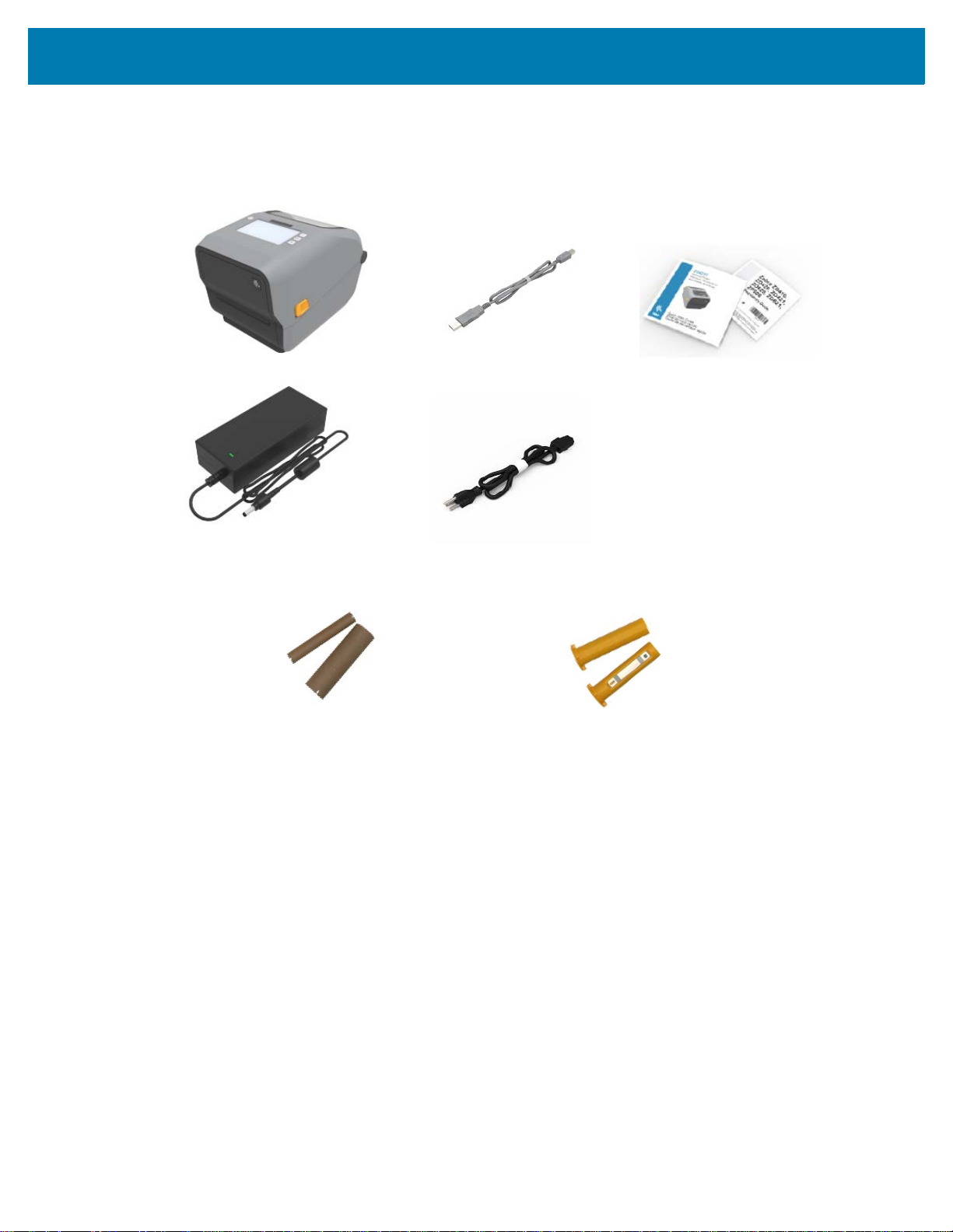
What’s in the Box?
USB Cable
Printer
Power Cord (varies by locale)
Non-Zebra 300 Meter Ribbon Adapters
Printer Documentation
Included with Thermal Transfer Printer (uses ribbon rolls)
Empty Starter Ribbon Cores
Power Supply
After unpacking, make sure you have all parts shown below. Follow the procedures for inspecting the
printer to familiarize yourself with printer parts so you can follow the instructions in this book
.
Introduction
Unpack and Inspect the Printer
When you receive the printer, immediately unpack it and inspect for shipping damage.
• Save all packing materials.
• Check all exterior surfaces for damage.
• Open the printer and inspect the media compartment for damage to components.
If you discover shipping damage upon inspection:
• Immediately notify the shipping company and file a damage report. Zebra Technologies Corporation
is not responsible for any damage to the printer incurred during shipment, and will not cover the
repair of this damage under its warranty policy.
• Keep all packaging material for shipping company inspection.
• Notify your authorized Zebra
Refer to the Zebra Web site for ‘How To’ videos on packing and unpacking your printer. Go to About on
page 11 for links to one of the 5 basic Link-OS printer variations.
®
reseller.
18
Page 19
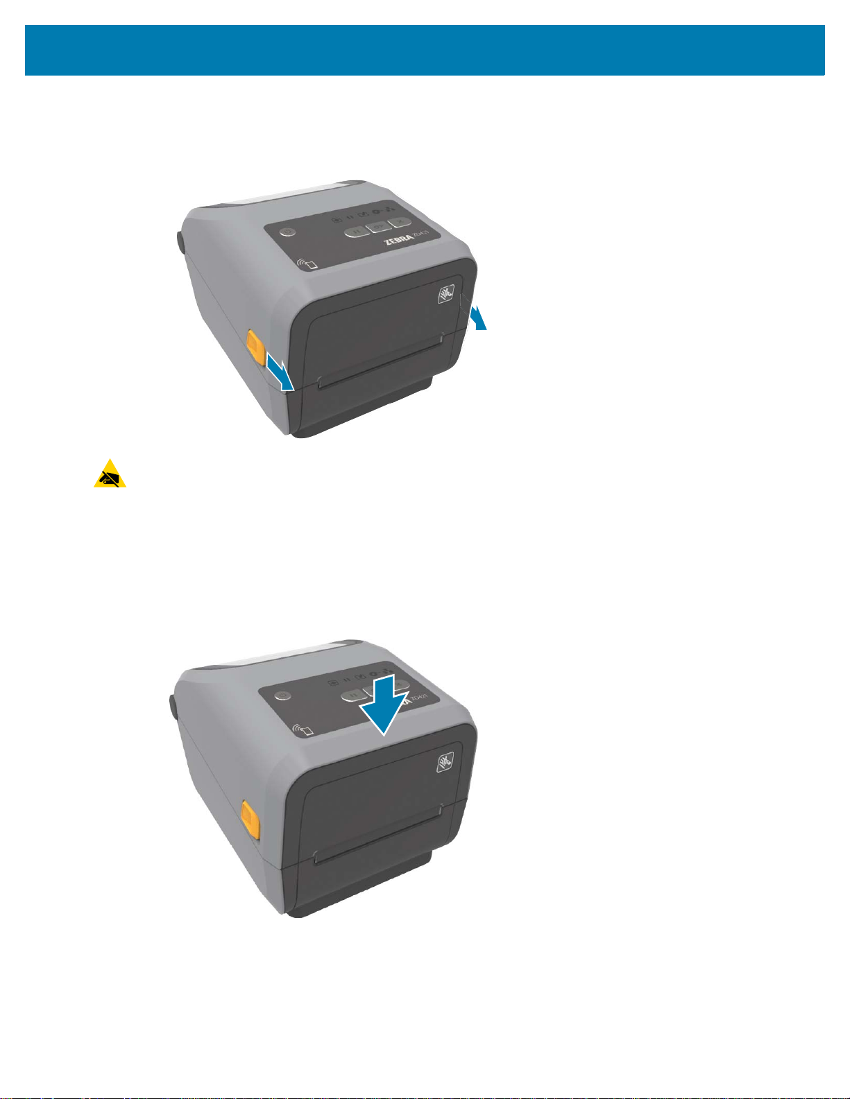
Open the Printer
To access the media compartment, pull the release latches towards you and lift the cover. Check the
media compartment for loose or damaged components.
Introduction
CAUTION—ESD: Observe proper electrostatic safety precautions when handling static-sensitive
components such as circuit boards and printheads.The discharge of electrostatic energy that accumulates
on the surface of the human body or other surfaces can damage or destroy the printhead and other
electronic components used in this device. You must observe static-safe procedures when working with
the printhead or the electronic components under the top cover.
Closing the printer
Lower the top cover. Push down on the front of the printer to close. Push the center or both corners of the
printer firmly until both side latches lock.
19
Page 20

Printer Features
This section will help you identify features of these Zebra® Link-OS 4-inch desktop thermal label printers,
the ZD621 and ZD421. ‘How to’ videos on the Zebra Web site include a Printer Features video; as well as;
other printer setup and task specific videos. Links to these five (5) Link-OS 4-inch desktop printers are:
• ZD621 Thermal Transfer Printer — zebra.com/
• ZD621 Direct Thermal Printer — zebra.com/
• ZD421 Thermal Transfer Ribbon Cartridge Printer — zebra.com/
• ZD421 Thermal Transfer Printer — zebra.com/
• ZD421 Direct Thermal Printer — zebra.com/
• ZD621R Thermal Transfer Printer — zebra.com/
ZD621t-info
ZD621d-info
ZD421t-info
ZD421d-info
ZD621r-info
ZD421c-info
20
Page 21
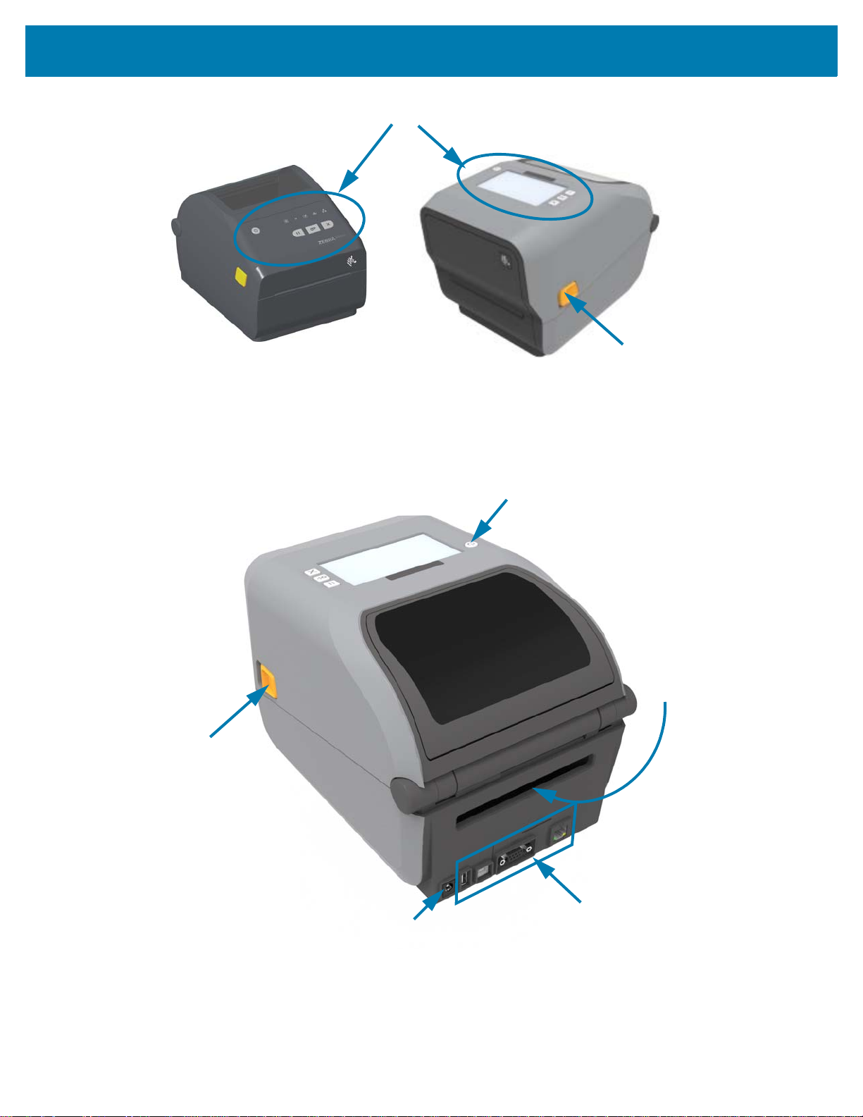
Interface and Connectivity Module
Slot Access
User Interface
Release Latch
DC Power
Receptacle
Power Button
Release
Latch
Fan-Fold Media
Entry Slot
For more details on printer controls, go to Controls and Indicators on page 37.
Printer Features
21
Page 22
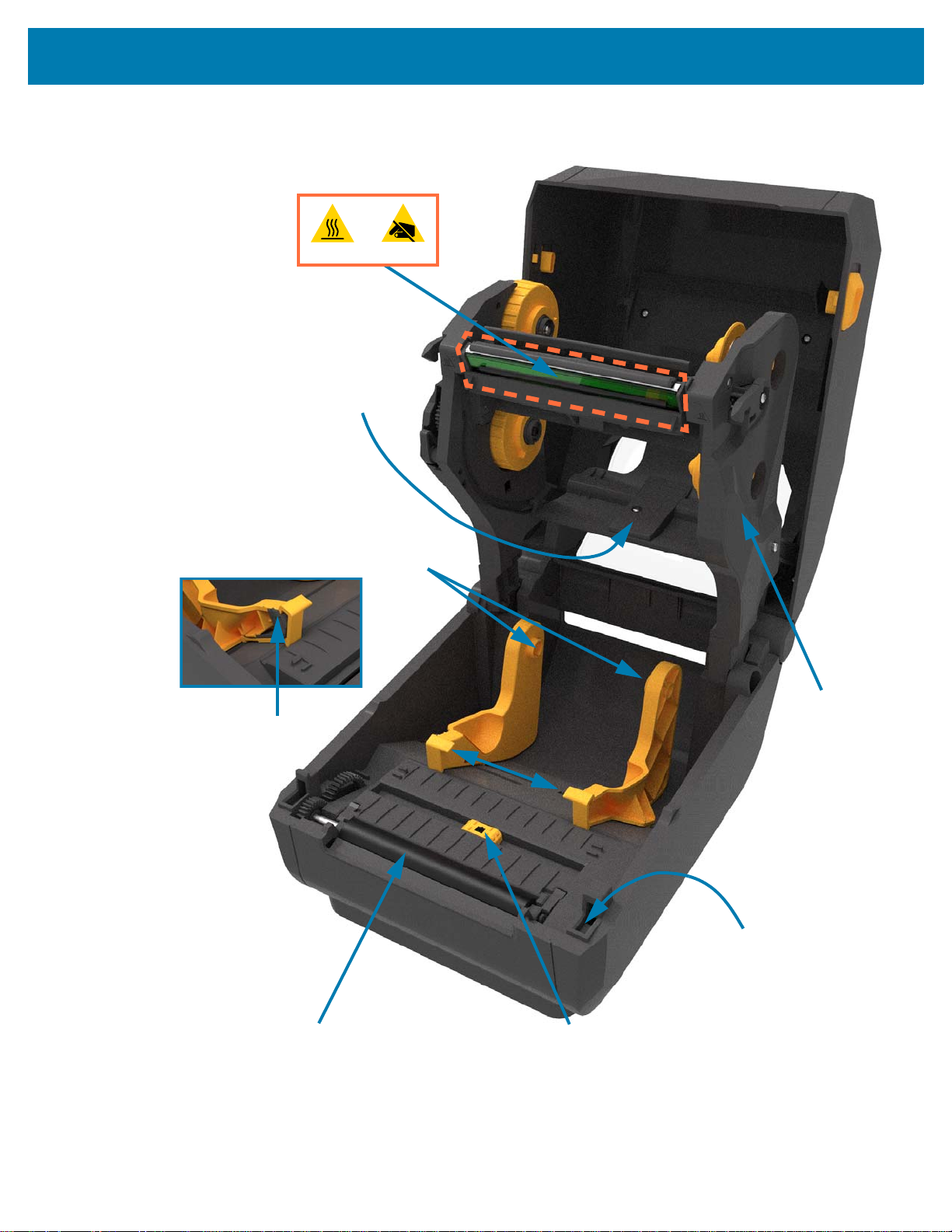
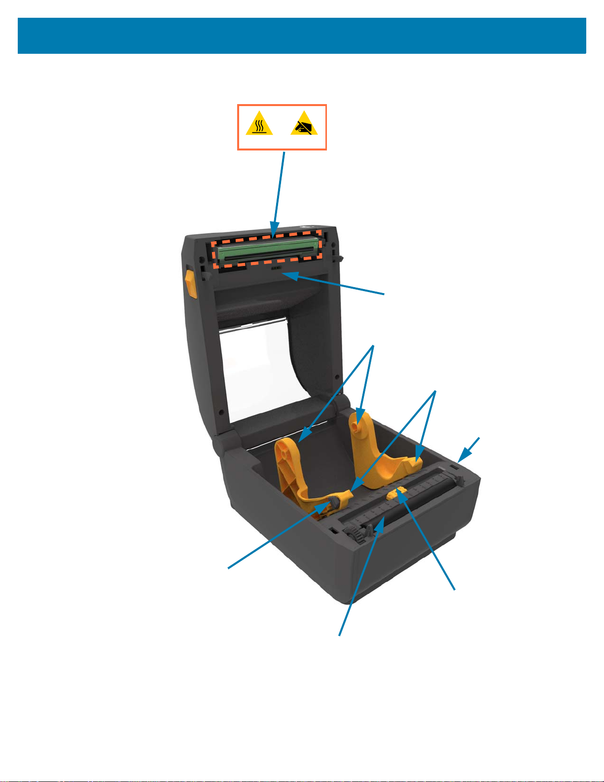
Printer Features
Movable Sensor
(Black Mark and Lower Web/Gap)
Media
Guides
Head-Up Sensor
(inside)
Media Guide
Stop
Platen (Drive) Roller
Roll
Holders
Upper Web (Gap)
Array Sensor
(other side)
Ribbon
Carriage
Printhead
Inside the ZD421 Dual Capacity Ribbon Roll Printer
22
Page 23
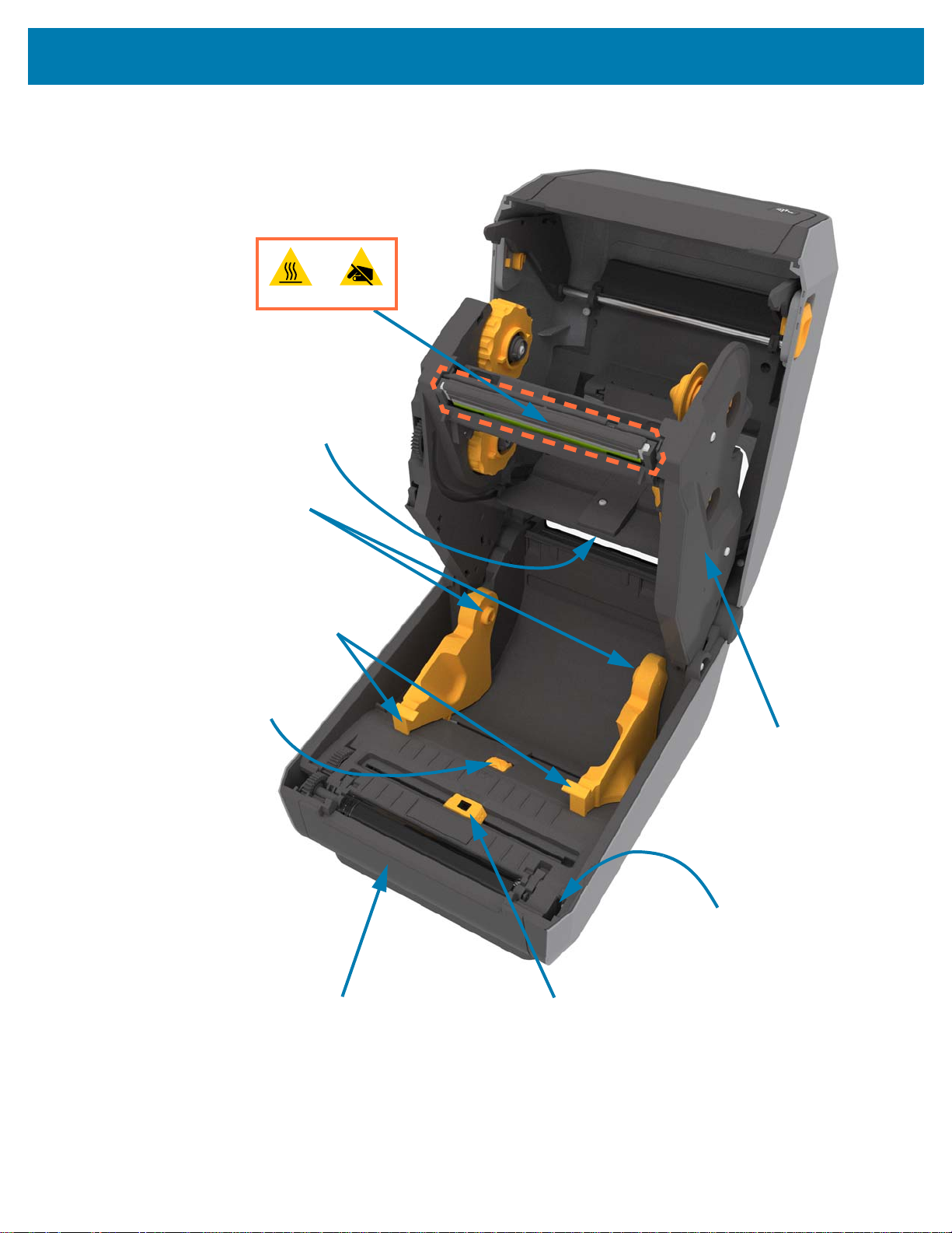
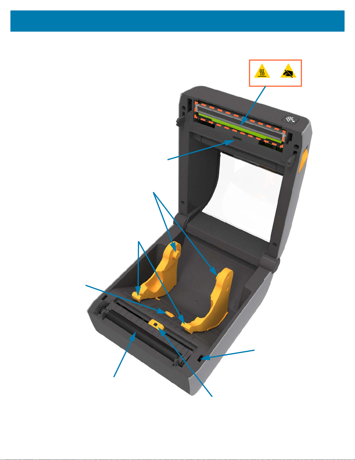
Printer Features
Movable Sensor
(Black Mark and Lower Web/Gap)
Media Guides
Head-Up Sensor
(inside)
Media Guide Stop
Adjustment
Platen (Drive) Roller
Roll Holders
Upper Web (Gap)
Array Sensor
(other side)
Ribbon Carriage
Printhead
Inside the ZD621 Dual Capacity Ribbon Roll Printer
23
Page 24
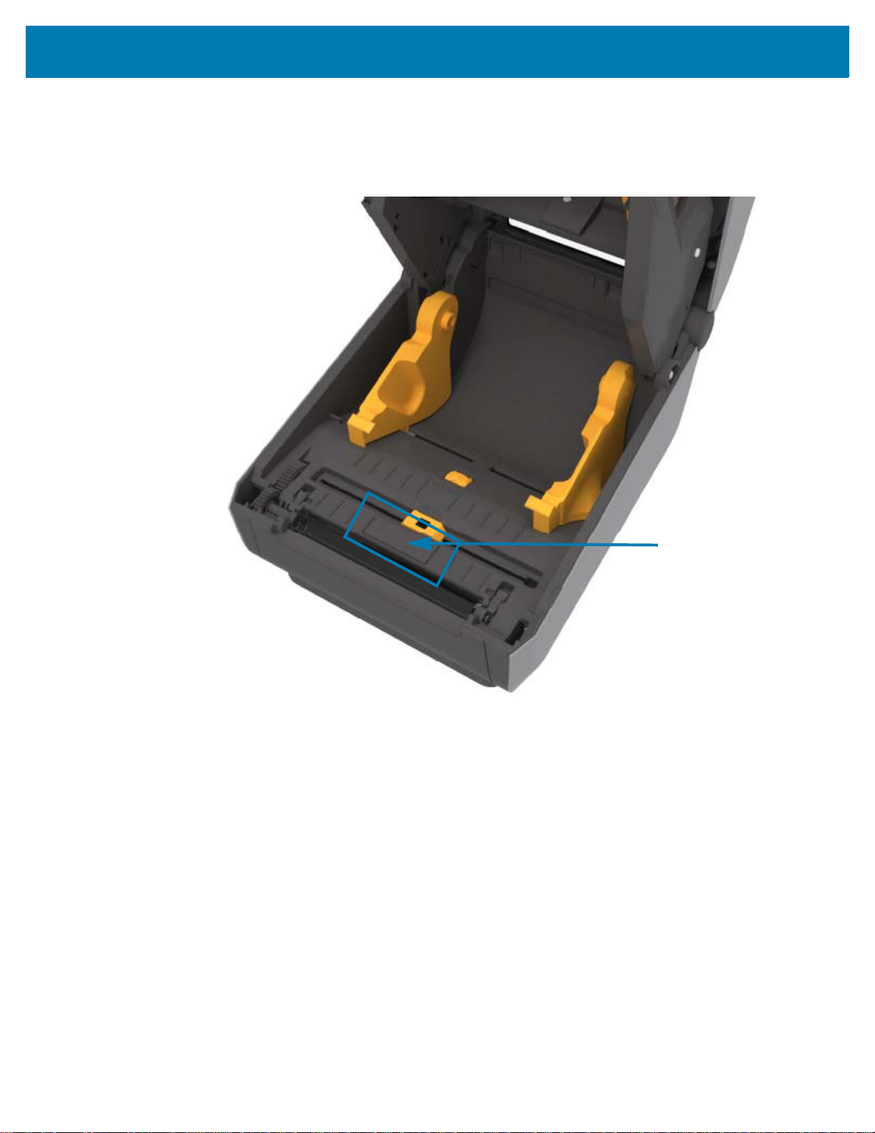
Printer Features
RFID Antenna Dome
Identifying the ZD621R RFID Antenna Location
The ZD621R printers antenna is located between the platen rollover and movable media sensor channel in
the center of the printer. This is the only visible RFID item other than the Color Touch Display when on and
the product branding and labeling.
24
Page 25
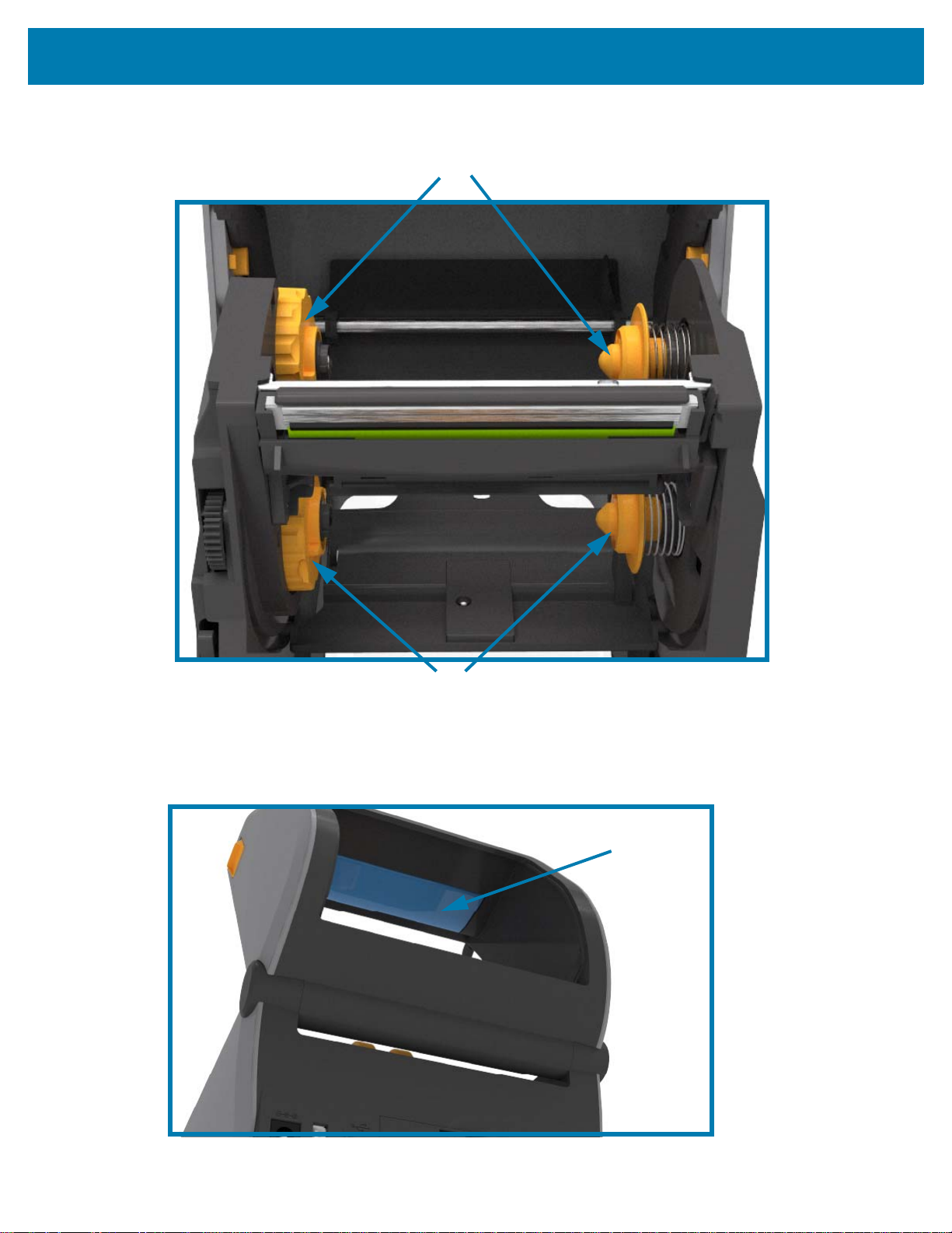
Printer Features
Take Up Spindles
Supply Spindles (full ribbon rolls)
Media Dancer
(ZD621 Only)
Dual Capacity Ribbon Chassis - Ribbon Roll Holders
Media Dancer - ZD621 Printer Models Only
The printer’s window is removed to show the Media Dancer (plate). The Media Dancer is re-colored to
make it easier to locate. It is the same color as the dark gray parts adjacent to it.
25
Page 26
Printer Features
Movable Sensor
(Black Mark and Lower Web/Gap)
Media Guides
Head-Up Sensor
(inside)
Media Guide Stop
Platen (Drive) Roller
Roll Holders
Upper Web (Gap)
Array Sensor
Printhead
Inside the ZD421 Direct Thermal Printers
26
Page 27
Printer Features
Movable Sensor
(Black Mark and Lower Web/Gap)
Media
Guides
Head-Up Sensor
(inside)
Media Guide
Stop
Adjustment
Platen (Drive)
Roller
Roll Holders
Upper Web (Gap)
Array Sensor
Printhead
Inside the ZD621 Direct Thermal Printers
27
Page 28
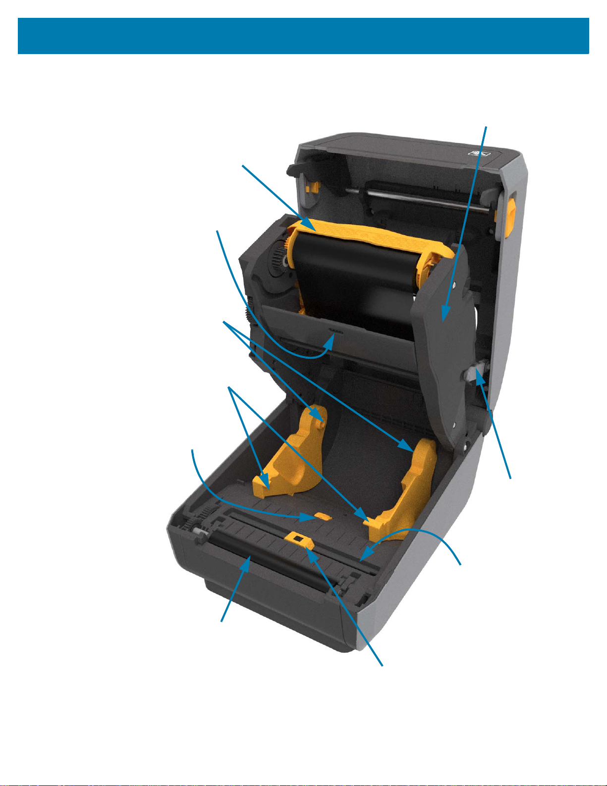
Printer Features
Movable Sensor
(Black Mark and Lower Web/Gap)
Media Guides
Head-Up Sensor
(inside)
Media Guide Stop
Adjustment
Platen (Drive) Roller
Roll Holders
Ribbon Cartridge
Shown Installed
(sold separately)
Upper Web (Gap)
Array Sensor
Release
Arms (2)
Ribbon Drive
Transport
Inside the ZD421 Ribbon Cartridge Printer
28
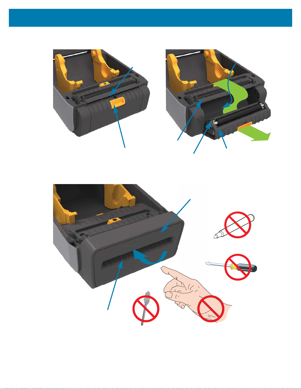
Page 29
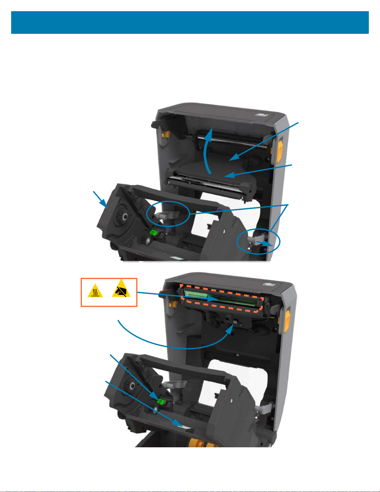
Printer Features
Backside of
Printhead
Printhead
Actuator Arm
Ribbon
Transport
Release
Arms
Printhead
Ribbon Cartridge
Authentication and Status
Interface
Ribbon Sensor
Ribbon Sensor’s
Reflector
Accessing the Printhead of the Ribbon Cartridge Printer
To access the printhead:
1. Pull both release arms out (lighter gray parts).
The ribbon drive transport drops down.
2. Lift printhead actuator arm up to access the printhead.
29
Page 30
Printer Features
Door Latch
Label Taken
Sensor
Peel Roll
Dispenser Door
Label Liner
Exit Area
Label Peel Bar
Media Exit Slot
Cutter Module
Label Dispenser Option (field installable) - All Models
Cutter Option (field installable) - All Models
30
Page 31

Printer Features
Label Taken
Sensor
Label Taken
Sensor
Cut Label Landing
Area
Linerless Media Tear-Off Option (Direct Thermal Models Only)
Linerless Cutter Option (Direct Thermal Models Only)
31
Page 32

Printer Features
203 dpi Standard Platen (black)
300 dpi Standard Platen (gray)
203 dpi Linerless Platen (reddish-brown)
300 dpi Linerless Platen (brown)
Identifying Platen Drive Rollers Types
The platen (drive) rollers are colored differently to identify the platen type and print resolution of your
printer (and the platen). Do not exchange platen types unless instructed to by an upgrade procedure or
Zebra technical support. The printer will not operate correctly and may cause a variety of problems
requiring maintenance.
32
Page 33

Printer Power Supply Options
Attached Power Supply
Base, Rear View
Attached Power Supply
Base, Front View
ZD-Series printers offer field-installable attached power options: an attached power supply base or a
battery power base. These options easily attach with screws and replace the power supply that was
included with your printer.
Attached Power Supply Base
Printer Features
33
Page 34

Printer Features
Battery Power
Base
Battery Status and
Charge Indicators
Printer with Battery Base Installed Battery
Power
Interface
Power Input Battery Control
Button
Battery Ready to Install Printer with Battery installed
Battery Latch
Attached Battery Base and Battery
IMPORTANT: The battery can be charged, checked, and configured for storage all without the printer. A printer
power supply or other approved Zebra power source is needed to charge your battery.
34
Page 35

Printer Features
Kensington Lock Slot
Cabinet Lock
ZD621 Direct Thermal Locking Printer Features
This option is only available in Direct Thermal Healthcare printer models. It includes a lock and key access
to the printer’s media compartment and a Kensington Lock Slot on the back panel of the printer to secure
the printer. For more information on the Locking Printer option, go to ZBI 2.0 ™ — Zebra Basic Interpreter
on page 223.
Go to Color Touch Display and Controls on page 68 for more information on printer controls.
35
Page 36

Zebra Print Touch
Print Touch Location
(Passive NFC)
The Zebra Print Touch ™ feature allows you to touch an Android ™ -based, Near Field Communication
(NFC)-enabled device such as a smart phone or tablet to the printer’s Print Touch logo to pair the device to
the printer. Print Touch is available on models with a factory installed networking (Wi-Fi, wired Ethernet,
Bluetooth, and Bluetooth Low Power). This capability allows you to use your device to provide information
for which you are prompted and then print a label using that information.
IMPORTANT: Some mobile devices may not support NFC communication with the printer until you
configure the required NFC settings in your device. If you encounter difficulties, consult your service
provider or your smart device manufacturer for more information.
Printer Features
Data encoded into the tag includes:
• A URL for a Zebra QuickHelp style support web page
• The printer’s unique Bluetooth Low Energy MAC address
• The printer’s Bluetooth Classic MAC address (if present)
• The printer’s Wi-Fi (WLAN) MAC address (if present)
• The printer’s Ethernet (LAN) MAC address (if present)
• The printer SKU – ex. ZD6A142-301F00EZ
• The printer’s unique serial number
The NFC tag can be used to:
• Facilitate Bluetooth pairing with a compatible mobile device.
• Launch an application.
• Launch a mobile browser to a web page.
36
Page 37

Controls and Indicators
This section discusses the two user control panel variations and their functionality.
User Interface
The primary user controls are found on the front of the printer. The ZD-Series Desktop printers support two
user interface options.
• Standard User Interface — This interface provides basic control and status needed by an operator.
Printer operating status is reported by five (5) icon indicator lights. The icons represent several
functional areas of operation. The indicator lights, as a group, provide a wide range of printer status
notifications when used in combination. They are visible from a greater distance than you can read
on a printer with a display. Go to Meaning of the Indicator Light Patterns on page 41.
• This interface supports operator tasks of replacing printing supplies (labels, receipt paper,
transfer ribbon, etc.) when prompted by two indicators.
• Status indicator’s icons represent a functional area of printer operation.
• Status indicator lights typically use color to show the operator the functional status of the printer.
The status indicator lights may be off (not lit), red, green, or amber (orange/yellow). Red is
‘needs attention’ or ‘not ready’. Green is for ‘ready’ or ‘functioning’. Amber (orange/yellow) is for
busy or active process (data downloading, over-temperature cooling cycle, etc.). An off or un-lit
status indicator does not require the operators attention.
• A status indicator can flash (blink), fade (bright to off), alternate between colors, or remain on in a
variety of patterns that denote various printer activities, and operational status as a group.
• Control buttons are used in various combinations to access internal utilities that calibrate the
printer to your media and make limited print settings.
• Color Touch Display and Interface — The Color Touch Display interface provides easy access to
printer setup, configuration, and is customizable for all user types. The interface includes all the
Standard User Interface controls and indicators to provide you with common functionality and
behaviors for these Link-OS printer models.
• The display option provides written printer status and messages.
• The display supports 19 languages, selectable by the operator, or with programming.
• It has a menu system. Users can make changes to print settings (darkness, speed, etc.), run
utilities, and set wired and wireless communication interfaces (Serial, Ethernet, Wi-Fi, etc.) that
are installed on your printer.
37
Page 38

Standard Interface Controls
Pause
Feed8
Cancel
DataStatus NetworkMediaPause
Power
Status Indicators
Power Button
Pause Button
Feed Button
Cancel Button
Color Touch Display
and Interface
Status Indicators
Controls and Indicators
38
Page 39

Controls and Indicators
1.
Power Button — Turns power ON and OFF in the printer. It is also used to initiate low-power sleep and
wake states.
• Initial Power ON — Press the Power button until the printer’s indicator lights flash on. The indicator
lights will flash on and off in various combinations while the printer does self diagnostics,
configuration checks, and integrate optional components which will take several seconds to
complete.
The Status indicator will turn solid GREEN indicating the printer is ready for normal print operations.
• Energy Star (Low Power Mode) — Pressing and releasing the button once will cause the printer to
enter Energy Star low power mode. The printer will minimize power use. All the indicators will be off
except the Status Indicator will slowly change between On and Off to indicate Energy Star Mode.
• Power OFF with Energy Star Delayed — Press and Hold the button for 4-9 seconds. The operator
can start a batch print job and put the printer into the low power consumption state of Sleep mode —
after the job has finished.
• Power OFF / Shutdown — Press and Hold the button for 4-9 seconds. The printer will turn OFF.
• Power Failure Recovery Mode — This printer feature is activated by a hardware jumper setting on
one of the optional Printer Connectivity Modules installed in the printer. Go to Setting the Power
Failure Recovery Mode Jumper on page 224.
• The printer will automatically Power ON when plugged into an active (ON) AC power source.
• Supports Sleep Mode and Power OFF with Sleep mode Delayed.
• A Power OFF/Shutdown will reset the printer and then runs the Initial Power ON sequence.
NOTE: The Power Failure Recovery Mode is only available on printers with a Printer Connectivity Module
installed in the printer.
2. Status Indicator — Primary status indicator for overall printer health and operational status. This
indicator is also known as the Power indicator.
• Green: Ready for print and data activity.
• Green, Slowly Changing between ON and OFF: Printer is in Sleep Mode.
• Red: Media out, media detection error, head (cover/printhead) open, cut error, printhead
authentication failure.
• Amber: Printhead Over Temp (temperature), printhead element failure, out of memory while storing
content (formats, graphics, fonts, etc.), and interface power fault for USB Host or Serial ports.
• Blinking Amber: Printhead Under Temp (temperature)
• Blinking Red: Printhead Over Temp (temperature) — this status is coupled with blinking red Pause
indicator. Requires cooling and printer restart.
3. Pause Indicator — The printer is in Pause mode when the Pause indicator light is on. A label (print
form) or all labels (print forms) in the print buffer’s queue can be canceled when the Pause indicator is
on using the Cancel button.
• Amber: The printer is paused. Print, label FEED (advance), and other label routines are suspended
until the pause state is removed by pressing the Pause button.
• Blinking Red: Printhead Over Temp (temperature) — this status is coupled with blinking red Status
indicator. Requires cooling and printer restart.
4. Data Indicator — Indicates the status of data transfer activity.
• Off: Data is not being transferred.
39
Page 40

Controls and Indicators
• Green: A data communication operation has not finished, but is not actively being transferred.
• Blinking Green: Data communications are in process.
• Blinking Amber: Out of memory while storing content (formats, graphics, fonts, etc.).
5. Supplies Indicator — Indicates media (label, receipt, tags, transfer ribbon, ribbon cartridge, etc.) status.
• Red: There is a media out condition.
• Blinking Red: Ribbon Out.
• Blinking Red and Amber: Ribbon Cartridge Low (ZD421 Cartridge printers only).
• Blinking Amber: Ribbon In (ZD421 Cartridge printers only) detected while the printer is attempting to
print in direct thermal mode.
6. Network Indicator — Indicates network activity and status.
• Amber: 10 base Ethernet (LAN) connection detected.
• Green: 10/100 Ethernet (LAN) connection detected or when Wi-Fi (WLAN) has a strong signal and
is connected.
• Red: when an Ethernet (LAN) or Wi-Fi (WLAN) fault occurs.
• Blinking Red: during Wi-Fi (WLAN) association.
• Blinking Amber: during Wi-Fi (WLAN) authentication.
• Blinking Green: when Wi-Fi (WLAN) has completed, but has a weak signal.
7. Cancel Button — Cancels print jobs.
• Only functional when the printer is in the Pause state.
• Pressing the Cancel button once causes the printer to cancel printing the next format in the print
buffer.
• Pressing and holding the button for two seconds cancels printing of ALL pending formats.
8. FEED (Advance) Button — Advance a label (print form/format).
• Feed One Label - Pressing (and releasing) the FEED button when the printer is not printing, causes
the printer to advance media one (1) blank form/format length (label, receipt, tag, ticket, etc.).
• Advance Multiple Labels - Pressing and Holding the FEED button when the printer is not printing,
causes the printer to advance labels until released. It finishes advancing to the beginning position of
the next label.
• Reprint Last Label (activated via a SGD command: ezpl.reprint_mode) - The intended purpose of
this feature is to allow reprint of a failed media print. If the printer runs out of media (paper, labels,
transfer ribbon, etc.), then the printer can re-print the last label (print form/format). The print buffer
that stores the print image available for reprint is cleared when the printer gets turned off or is reset.
9. Pause Button — Pauses print and media movement actions.
• Pressing the Pause button will stop print activities and place the printer into a ‘Pause’ state. The
printer will complete printing a label that is printing before it pauses.
• The Pause indicator will display Amber (orange/yellow) to indicate the Pause state.
• Pressing the Pause button while in Pause state will return the printer to normal operation. If printing
a multi label (form/format) job or another print job is waiting to print in the print queue, then printing
will resume print jobs.
40
Page 41

Controls and Indicators
Indicator States
Steady-On Flashing Fade Off
Meaning of the Indicator Light Patterns
All of the Link-OS 4 inch printers have status indicators. The indicators may be off or on in a variety of
lighting patterns of red, green, or amber (orange/yellow). The status indicators can flash (blink), fade
(bright to off), alternate between colors, or just remain on. The status information that these lighting
patterns represent is detailed in this section.
Status - Typical Operating Conditions
Printer Ready
The printer is powered on and ready to print.
Pause
The printer is paused. The operator must press the Pause
button to resume print operations.
Media Out
The media (labels, receipts, tags, tickets, etc.) supply is out.
The printer needs attention and cannot continue without user
intervention.
Ribbon Out
Detected end of ribbon roll (reflective end on ribbon rolls), a
missing ribbon cartridge, or the ribbon cartridge needs
replaced to continue printing when the printer is in thermal
transfer mode.
Ribbon Low (Ribbon Cartridge Printers Only)
Default value is 10% of ribbon remaining. The Media
indicator flashes red and yellow while the Status indicator
is solid yellow.
41
Page 42

Controls and Indicators
Ribbon In (Ribbon Cartridge Printers Only)
Transferring Data
Data Transfers Paused
Thermal Transfer printer is in Direct Thermal Mode and has a
ribbon cartridge installed. Remove the ribbon cartridge to
continue printing in direct thermal mode.
Data communications are in process.
A data communication operation has not finished, but is
not actively being transferred.
Out of Memory
Cover Open/Printhead (PH) Open
Cut Error (Binding)
Cartridge Authentication Failed
Out of memory while storing content (formats, graphics, fonts,
etc.).
The cover (printhead) is open. The printer needs attention
and cannot continue without user intervention.
The cutter blade is bound and is not moving properly.
The ribbon cartridge can not be authenticated or has been
altered. The printer only supports Genuine Zebra Ribbon
Cartridges and does not support refurbished or non-Zebra
cartridges.
42
Page 43

Status - Printhead Operation
Hot Surface Caution • The printhead may be hot and could cause sever burns. Allow the printhead to
cool.
Printhead Over Temp
Printhead Under Temp
Printhead Shutdown
Controls and Indicators
The printhead is over temperature and paused to allow the
printhead to cool. The print operation will resume after the
printhead has cooled.
The printhead is under temperature. Typically, the
operating environment is below the printer’s minimum
operational temperature.
Printhead Resolution Error
Unauthorized Printhead Error
The printhead is over temperature. Turn the printer OFF.
After several minutes to allow the printer to completely cool,
turn the printer ON.
The printer is unable to read the printhead resolution type
(dpi). The printhead has been replaced incorrectly or with
non-Zebra printhead.
The printhead was replaced with one that is not a genuine
Zebra printhead. Install a genuine Zebra printhead to
continue.
43
Page 44

Controls and Indicators
Status - Bluetooth Low Energy (BTLE) Option
Bluetooth LE Paired
Bluetooth Low Energy has paired.
Bluetooth LE Failed to Pair
Bluetooth Low Energy has failed to pair.
Status - Ethernet (LAN) Option
Ethernet (LAN) No Link
No Ethernet link is available. NETWORK status is light off
Ethernet (LAN) 100base Link
Ethernet (LAN) 10base Link
Ethernet (LAN) Link Error
A 100 Base link was found.
A 10 Base link was found.
An error condition exists. The printer is not connected to your
network.
44
Page 45

Status - Wi-Fi (WLAN) Option
Controls and Indicators
Wi-Fi
Connecting to WLAN
Wi-Fi (WLAN) 100base Link
Wi-Fi (WLAN) 10base Link
The light flashes red while the printer associates with the
network.
The light then flashes yellow while the printer is
authenticating with the network.
The printer is connected to your network and the Wi-Fi
signal is strong.
The printer is connected to your network and the Wi-Fi
signal is weak.
f
Wi-Fi (WLAN) Link Error
Battery Indicators and Controls
The optional printer battery accessory has a simple, one button, 4 LED indicator light user interface to
control and display battery status and health. The battery acts as a UPS (uninterruptible power supply) for
the printer. For more information on using the battery with your printer and power saving modes (Sleep,
Shutdown, etc.), go to Printing with the Attached Battery Base and Battery Option on page 219.
An error condition exists. The printer is not connected to
your network.
45
Page 46

Controls and Indicators
Rear of Battery
Battery Control
Button
Health Indicator
Charge Level Indicators (3)
Charge Level
Indicators (3)
Health Indicator
Battery Control Button — The button helps you control the battery, both inside and outside of the printer.
• Battery On - Press and release
• Wakes up (activates power) the battery from Sleep or Shutdown Modes. The battery health and
charge status are checked. The battery indicators all flash on and off together 3 times. The
operator now has one (1) minute to turn the printer on before the battery reverts back to the
previous Sleep or Shutdown Mode.
• Battery displays the battery level charge during the first ten (10) seconds after internal battery
health checks are complete
• Shutdown Mode - Press and hold the button for 10-11 seconds and release. The battery begins
shutdown and approximately 3 seconds later all of the battery LEDs will flash three (3) times to
let you know the battery has shut down.
Battery Health Indicator — Displays the battery’s charging status and health of the battery.
• Green - Good health, charge complete and ready to operate.
• Amber - Charging (printer is OFF).
• Red - Battery has an internal error. Remove the battery and go to Troubleshooting on page 274.
• Flashing Red - Charging error - over or under temperature, internal monitoring error, etc.
Battery Charge Level Indicator — Displays the battery’s charging status and health of the battery.
• Three green bars on, no flashing - Battery is fully charged. (The battery will not start charging
• Two green bars on with the top bar flashing. Less than full charge.
• One green bar flash - Time to charge your battery!
• No bars on - Battery needs charging, but the Battery Health Indicator flashes when the Battery
Control Button is pressed. The printer can not be turned on.
• Amber - Charging.
46
Page 47

Install Hardware Options
This section assists you installing common printer connectivity modules and media handling options.
IMPORTANT: To simplify and speed up the setup process, install all connectivity modules and media
handling options before setting up and using your printer for the first time.
IMPORTANT: It is strongly recommended that you update your printer’s firmware after the printer has
completed the setup process. Many of these options have internal firmware that require an update to
operate properly with the printer’s Main Logic Board’s installed firmware version.
Field Installable printer Accessories and Options
Printer Connectivity Modules
The connectivity module’s access door must be removed prior to installing the following options —
Accessing the Connectivity Module Slot on page 49.
• Wireless Connectivity Module — go to Installing the Wireless Connectivity Module on page 53.
• Wi-Fi 802.11ac, Bluetooth 4.2, BTLE 5, and MFi 3.0
• ZD421 Serial Port — go to Installing the Serial Port Module on page 50
• RS-232 DB-9 connector with DTE/DTC auto-switching — go to Serial Port Interface on page 308
• ZD421 Internal Ethernet (LAN - wired) — go to Installing the Internal Ethernet (LAN) Module on
page 51
• RJ-45 connector
• Fast Ethernet 10/100 auto-switching, 10Base-T, and 100Base-TX networks.
Media Handling Options
The printer’s standard bezel must be removed prior to installing the following options — go to Removing
the Standard Bezel on page 56.
• Label Dispenser (Peel-Off Liner and Present Label for Operator) — go to Installing the Label
Dispenser on page 57.
• General Purpose Media Cutter — go to Installing the Standard Media Cutter on page 58.
• Linerless Media Cutter — go to Installing the Linerless Media ‘Tear-Off’ Bezel on page 60.
• Linerless Media ‘Tear-Off’ Label Bezel — go to Installing the Linerless Media ‘Tear-Off’ Bezel on
page 60.
47
Page 48

• Printer Resolution Upgrade Kits (203 dpi and 300 dpi) — go to Print Resolution Upgrade Kits on
page 63.
• Media Roll Adapters for 38.1 mm (1.5 in.), 50.8 mm (2.0 in.), or 76.2 mm (3.0 in.) I.D. media cores go to Media Roll Core Size Adapters on page 61.
• Fan-Fold Media Access Cover for thermal transfer printers.
Power Base Options
The ZD-Series (ZD621 and ZD421) printers are supported with power base field upgrade kits for each the
direct thermal and thermal transfer versions of these printers.
• Attached Power Supply Base (power supply included) — go to Installing the Attached Power Supply
Base Options on page 64.
• Battery Power Base (battery pack sold separately) — go to Installing the Attached Battery Base
Options on page 66.
• Battery Pack (battery power base sold separately) — go to Installing the Battery into the Attached
Power Base on page 67.
Install Hardware Options
48
Page 49

Install Hardware Options
Printer Connectivity Modules
The connectivity modules can be easily installed without tools.
CAUTION—ESD: The discharge of electrostatic energy that accumulates on the surface of the human
body or other surfaces can damage or destroy the printhead or electronic components used in this device.
You must observe static-safe procedures when working with the printhead or the electronic components.
Power Failure Recovery Mode Jumper (OFF by Default)
All of the Printer Wired Connectivity Modules have a Power Failure Recovery jumper. It is set to the OFF
position by default. With the jumper set to ON, the printer will automatically Power ON when plugged into
an active (ON) AC power source (and not power off). Go to Standard Interface Controls on page 38 Power Button - Power Failure Recovery Mode for power ON/OFF behaviors. Go to Setting the Power
Failure Recovery Mode Jumper on page 224 for instructions on activating the mode.
NOTE: The Power Failure Recovery Mode is only available on printers with a Printer Connectivity Module
installed in your printer.
Accessing the Connectivity Module Slot
1. Disconnect the DC power plug from the rear of the printer.
2. Push down on the top of the module access door with your finger tip.
The latch released.
3. Pull the door away and down to remove it.
49
Page 50

Install Hardware Options
Serial Port (RS-232)
Installing the Serial Port Module
1. With the DC power plug and module’s access door removed, slide the serial port module into the
printer.
2. Push the circuit card in slowly but firmly until the card is just past the inside lip of the access door.
3. Align the bottom of the serial port’s door cover to the bottom lip of the module access opening.
4. Swing the door up and snap the cover closed.
NOTE: For best printer performance, update the printer’s firmware after installing options or immediately
after the printer’s initial setup. Go to Updating Printer Firmware on page 273.
50
Page 51

Install Hardware Options
Ethernet Port (RJ-45)
Installing the Internal Ethernet (LAN) Module
1. With the DC power plug and module’s access door removed, slide the Ethernet module into the printer.
2. Push the circuit card in slowly but firmly until the card is just past the inside lip of the access door.
3. Align the bottom of the Ethernet port’s door cover to the bottom lip of the module access opening.
4. Swing the door up and snap the cover closed.
NOTE: For best printer performance, update the printer’s firmware after installing options or immediately
after the printer’s initial setup. Go to Updating Printer Firmware on page 273.
51
Page 52

Install Hardware Options
Removing Printer Connectivity Modules
Connectivity modules can be removed to reconfigure or repair a printer. You should not remove and
replace connectivity modules as a general practice.
1. Remove the interface cable (Ethernet or Serial).
2. Remove the module access door. Push down on the top of the door with your finger tip.
The latch released.
3. Pull the door away and down to remove.
4. Reattach the interface cable to the connectivity module and secure the cable.
5. Gently pull on the interface cable that is secured to the connectivity modul, and slowly pull the module
out of the printer.
6. Install a different connectivity module or reinstall the connectivity module’s access door.
7. Align it to the bottom lip of the access opening and swing it up to snap and lock in place.
52
Page 53

Install Hardware Options
Installing the Wireless Connectivity Module
Use this procedure to install the Wireless Connectivity Module.
CAUTION—ESD: The discharge of electrostatic energy that accumulates on the surface of the human
body or other surfaces can damage or destroy the printhead or electronic components used in this device.
You must observe static-safe procedures when working with the printhead or the electronic components.
Installation Preparation
1. Unload printer media.
2. Turn OFF the printer.
3. Disconnect any power or interface cables from the printer.
NOTE: No tools are needed for this procedure.
Access the Wireless Connectivity Area
1. Turn the printer over to access the Wireless Connectivity Door.
2. Push the latch at the top with your fingertip to open the module access door.
The printer base has a recessed area for your fingertip. The latch released.
3. Lift and swing the door up to remove it.
53
Page 54

Install Hardware Options
4.
Align the antenna arm (1) into the well.
5. Lower and align the module (2) to the printer's Wi-Fi connector (3).
6. Push the module (2) in gently but firmly until fully seated.
7. Align the shortest side of the Wireless Connectivity Door (1) to the shortest side of the opening.
8. Swing the door on the tab (1) in the middle of the door printer and swing the door closed.
9. Push the door to lock the latch.
NOTE: The Wireless Connectivity Door will not close correctly if the module has not been fully seated. This
is a good test to verify complete insertion.
54
Page 55

Install Hardware Options
5.
Place the three (3) Wi-Fi identification labels included on the bottom of the printer.
These assist with printer configuration (and later reconfiguration) of your printer. Mobile apps, use of
scanners, and printer support are aided by these printer configuration labels.
Label Locations for Thermal Transfer Printers
Label Locations for Direct Thermal Printers
55
Page 56
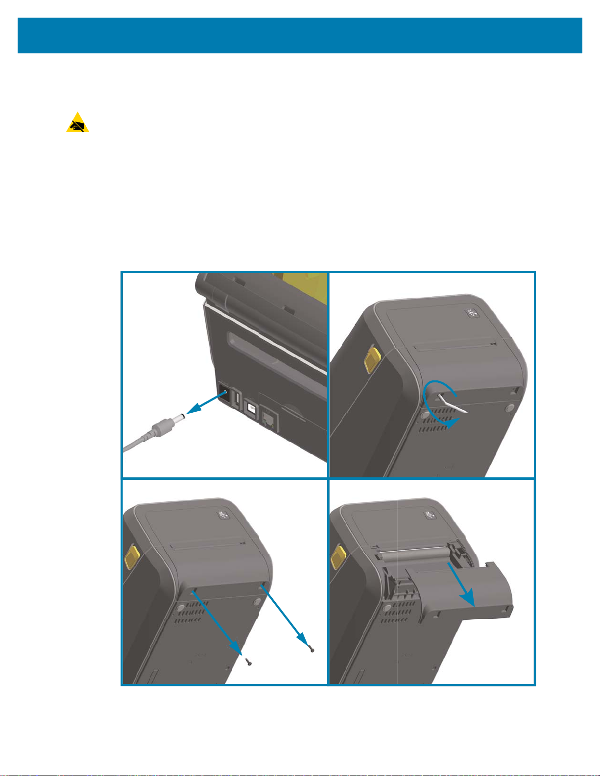
Media Handling Options
CAUTION—ESD: The discharge of electrostatic energy that accumulates on the surface of the human
body or other surfaces can damage or destroy the printhead or electronic components used in this device.
You must observe static-safe procedures when working with the printhead or the electronic components.
Removing the Standard Bezel
The standard bezel must be removed to mount your media handling option.
1. Disconnect the printer’s DC power input plug from the rear of the printer.
2. Turn the printer upside down. Remove the two (2) mounting screws with the supplied T10 wrench.
Save the screws.
3. Slide the bezel down the front about 12.5 mm (0.5 in.) and pull the loose bezel out.
Install Hardware Options
56
Page 57

Install Hardware Options
Installing the Label Dispenser
The standard bezel must be removed and DC input power disconnected before the Label Dispenser can
be installed. Go to Removing the Standard Bezel on page 56.
1. Place the label dispenser module and printer right side up with the top of the module 12.5 mm (0.5 in.)
below the bottom of the top cover.
2. Center and push the module into the front of the printer and slide it up until it stops.
3. Turn the printer upside down and attach the module to the printer with the two screws using the T10
wrench.
NOTE: For best printer performance, update the printer’s firmware after installing options or immediately
after the printer’s initial setup. Go to Updating Printer Firmware on page 273.
57
Page 58

Install Hardware Options
Installing the Standard Media Cutter
The standard bezel must be removed and DC input power disconnected before the Label Dispenser can
be installed. Go to Removing the Standard Bezel on page 56.
CAUTION: There are no operator serviceable parts in the cutter unit. Never remove the cutter cover
(bezel). Never attempt to insert objects or fingers in to the cutter mechanism.
IMPORTANT: Using un-approved tools, cotton swabs, solvents, etc. all may damage or shorten the
cutter’s usable life or cause the cutter to bind.
1. Place the Cutter module and printer right side up with the top of the module even with the bottom of the
top cover.
2. Center and push the module into the front of the printer and slide it up until it stops.
3. Turn the printer upside down and attach the module to the printer with the two screws using the T10
wrench.
NOTE: For best printer performance, update the printer’s firmware after installing options or immediately
after the printer’s initial setup. Go to Updating Printer Firmware on page 273.
58
Page 59

Install Hardware Options
Installing the Linerless Media Cutter
The standard bezel must be removed and DC input power disconnected before the Linerless Media Cutter
Module can be installed. Go to Removing the Standard Bezel on page 56.
1. Open the printer and remove replace the standard platen roller with the Linerless platen roller. Go to
Platen Cleaning and Replacement on page 255 for a replacement procedure. Go to Installing the
Printhead Resolution Upgrade Kits on page 63 to help you identify platen rollers.
2. Place the Cutter module and printer right side up with the top of the module even with the bottom of the
top cover.
3. Center and push the module into the front of the printer and slide it up until it stops.
4. Turn the printer upside down and attach the module to the printer with the two screws using the T10
wrench.
NOTE: For best printer performance, update the printer’s firmware after installing options or immediately
after the printer’s initial setup. Go to Updating Printer Firmware on page 273.
59
Page 60

Install Hardware Options
Installing the Linerless Media ‘Tear-Off’ Bezel
The standard bezel must be removed and DC input power disconnected before the Linerless Tear-Off
Bezel module can be installed. Go to Removing the Standard Bezel on page 56.
1. Open the printer and remove replace the standard platen roller with the Linerless platen roller. Go to
Platen Cleaning and Replacement on page 255 for a replacement procedure. Go to Installing the
Printhead Resolution Upgrade Kits on page 63 to help you identify platen rollers.
2. Place the Tear-Off bezel module and printer right side up with the top of the module even with the
bottom of the top cover. Center and push the module into the front of the printer and slide it up until it
stops.
3. Turn the printer upside down and attach the module to the printer with the two screws using the T10
wrench.
NOTE: For best printer performance, update the printer’s firmware after installing options or immediately
after the printer’s initial setup. Go to Updating Printer Firmware on page 273.
60
Page 61

Install Hardware Options
Media Roll Core Size Adapters
Adapter Kits
The media roll adapters kit includes three pairs of media roll adapters. The kits are for the following inner
diameter (I.D.) media cores
• 38.1 mm (1.5 in.)
• 50.8 mm (2.0 in.)
• 76.2 mm (3.0 in.)
Adapter Usage
• The adapters are intended to be permanently installed in the printer.
• They may be changed to support other media roll sizes that require one of these adapter sizes.
• The adapters may wear out if they are changed too much.
• Removing the media adapters to print on standard roll cores may leave plastic pieces in the media
roll holders side areas that rub against the roll. Push those attached pieces back into the side of the
media roll holder.
:
Installing Media Roll Adapters
1. Place one screw in the top adapter mounting hole of both of the roll holders. Start turning the screws
clockwise using the T10 wrench until the tip of the screw is just protruding through the inside of the roll
holder. The screws are self-tapping.
2. Place the adapter on the inside of the roll holder. The large side of the adapter is on top. The smooth
side (no ribs) faces the middle of the printer.
3. Align the adapter’s top screw hole to the protruding screw tip and pinch it tightly to the roll holder body.
Tighten the screw until there is no gap between the adapter and roll holder. Do not tighten beyond this
point. Over tightening will strip the thread.
4. Insert a screw in the bottom adapter mounting hole. Pinch the adapter tightly to the roll holder while
tightening the screw. Tighten the screw until there is no gap between the adapter and roll holder. Do not
tighten beyond this point. Over tightening will strip the thread.
5. Repeat step 1-4 for the other adapter and roll holder.
61
Page 62

Install Hardware Options
Example of Label Roll
with 76.2 mm (3.0 in.)
Inner Core
mounted on Media Core
Adapters
62
Page 63

Install Hardware Options
Print Resolution Upgrade Kits
There are four (4) print resolution upgrade kits. The same procedure is used to change all the printhead
resolution upgrade kits. Both the printhead and platen (drive) rollers must be changed and are resolution
dependent. The printer automatically detects the change in printheads and the platen roller materials are
identified by color.
Standard Printing
• Change the printer from 203 dpi to 300 dpi printing.
• Change the printer from 300 dpi to 203 dpi printing.
Linerless Printing (for Direct Thermal ZD621 printers only)
• Change the printer from 203 dpi to 300 dpi printing.
• Change the printer from 300 dpi to 203 dpi printing.
Printheads used in the upgrade kits include a 203 or 300 marking to help you keep the unpackaged
upgrade printhead separate from the original printhead. The original printhead contains no marking
identifying its print resolution.
The platen (drive) rollers are colored differently to help you keep from accidentally using the old platen
roller. Go to Identifying Platen Drive Rollers Types on page 32.
Installing the Printhead Resolution Upgrade Kits
1. Turn the printer off and disconnect the power.
2. Use the platen roller replacement procedure. Go to Platen Cleaning and Replacement on page 255.
3. Use the printhead replacement procedure. Go to Replacing the Printhead on page 259.
4. Re-attach power and turn the printer on. The printer will automatically detect the change in printhead
(but not the platen) when the printer verifies the printer’s configuration.
IMPORTANT: For best results and the latest printer features and operation, download and install the latest
printer firmware. Go to Updating Printer Firmware on page 273.
63
Page 64

Install Hardware Options
Thermal Transfer Printers Direct Thermal Printers
Installing the Attached Power Supply Base Options
The power base is ready to attach to the printer. The base is installed using T10 wrench (that you supply)
and the mounting screws provided with the upgrade kit. The direct thermal printer models attach to the
printer with three screws and thermal transfer printer models use four screws.
1. Remove any media rolls from the printer. Remove the original power supply cable from the back of the
printer.
2. Turn the printer over and align the power base to the bottom of the printer with the printer power plug
oriented toward the rear of the printer. The printer’s rubber feet align with recesses in the top of the
power base.
3. Use the screws provided to attach the power base to the printer. Three screws for Direct Thermal
printers. Four screws for Thermal Transfer printers. Tighten the screws using the T10 wrench supplied
in the kit.
64
Page 65

Install Hardware Options
DC Input Power
Plug
DC Input Power
Plug
4.
Insert the DC input power plug into the printer.
5. Re-connect the AC power cord to the printer power base.
65
Page 66

Install Hardware Options
T10
T10
Direct Thermal Printers Thermal Transfer Printers
Installing the Attached Battery Base Options
The battery base is ready to attach to the printer. The base is installed using a T10 wrench and the
mounting screws provided with the upgrade kit. The direct thermal printer models attach to the printer with
three (3) screws and thermal transfer printer models use four (4) screws.
1. Remove any media rolls from the printer. Remove the original power supply cable from the back of the
printer.
2. Turn the printer over and align the power base to the bottom of the printer with the printer power plug
oriented toward the rear of the printer. The printer’s rubber feet align with recesses in the top of the
power base.
3. Use the screws provided to attach the power base to the printer. Three (3) screws for Direct Thermal
printers. Four (4) screws for Thermal Transfer printers. Tighten the screws using the T10 wrench
supplied in the kit.
66
Page 67

Install Hardware Options
Battery Ready to Install Printer with Battery installed
Battery Latch
Installing the Battery into the Attached Power Base
IMPORTANT: The printer must have an Attached Battery Base installed and securely connected your
printer to keep from damaging the printer or battery.
1. Disconnect the printer’s external power supply from the DC Power Input located in the rear of the
printer.
2. Slide the battery into the battery base’s battery slot. Push the battery into the base until battery pack is
flush to the rear of the battery base, and the connectors on the battery pack are engaged with the ports
on the back of the printer.
IMPORTANT: Batteries are shipped in Shutdown Mode for safety and to keep the battery from discharging
during storage and shipping. The battery requires charging prior to initial use with the printer.
3. Attach the printer’s power supply to the battery to wake up the battery from Shutdown Mode and begin
its initial charge.
4. The printer must be fully charged before it’s first use. Go to Battery Indicators and Controls on page 45
to learn how to:
• Turn the battery on.
• Discover battery charge saving features and behaviors.
• Check the battery’s charge level and health.
5. The printer will take approximately two hours to reach a full charge. The battery status (health) indicator
(lighting bolt) will go from Amber (Charging) to Green (Charged)
67
Page 68

Color Touch Display and Controls
The printer's optional Color Touch Display provides easy access to your printer features, run print jobs, use
wizards to assist you, and a visually interactive display to help you quickly through tasks and
troubleshooting.
68
Page 69

Color Touch Display and Controls
Power Button
Pause Button
Feed Button
Cancel Button
Color Touch Display
and Interface
Status Indicators
Color Touch Display Printer Controls
The Color Touch Display interface provides easy access to printer setup, configuration, and is
customizable for all user types. The interface includes all the Standard User Interface controls and
indicators to provide you with common functionality and behaviors for these Link-OS printer models.
The printer’s Standard Interface control; Power, Pause, Feed, and Cancel Buttons with the five printer
Status Indicators are discussed in detail in Controls and Indicators on page 37.
69
Page 70

Home Screen
The printer’s Home screen shows you the printer’s current status and allows you to access the printer’s
menus. You can rotate the image of the printer 360 degrees to view it from all angles.
Printer Status
Color Touch Display and Controls
70
Page 71

Printer Info
Color Touch Display and Controls
Printers with the optional Color Touch Display interface include the following features:
• The printer's Standard Interface controls and status indicators provide quick and easy access to
common printed operations.
• The interactive Color Touch Display shows the normal operation status of the Home Screen with
access to:
• Print Status and Printer Info (information)
•Menu— Is used to set and control printing and communications
•Wizards—Allows you to change printer settings by going through prompts. Go to Printer Wizards
on page 72.
• Shortcuts — Allows you to quickly access the most recent menu items and to save your favorites.
Touch the darkened heart icon next to a menu item to save it to your list of favorites. Items in the
favorites are shown in the order in which they were saved.
71
Page 72

Color Touch Display and Controls
• The Color Touch Display shows the operator Alerts and Error messages
• If the background color of the Home Screen is yellow or red, the printer is in an alert or error state.
For more information, go to Resolving Alerts and Errors on page 274.
• Displays a quick link to online instructions and "How to ... ' videos for access by mobile devices.
• Access to Onboard Help.
Printer Wizards
The printer Wizards can assist you by walking you through the setup process for various printer settings
and features.
IMPORTANT: When using the Wizards, do not send data to the printer from the host. For best results, use
full-width media running the Print or Set All Wizards. If the media is shorter than an image to be printed, the
image may be truncated or print across multiple labels.
The following wizards are available:
• Set All Wizard—runs all the Wizards in sequence.
•System Wizard—sets up non-print related operating system settings.
• Connection Wizard—configures the printer’s connectivity options.
•Print Wizard—configures key printing parameters and features.
•RFID Wizard—sets up the RFID subsystem’s operations.
On the Home screen, touch Wizards to see the available options. For more information about individual
settings set by any of the wizards, go to User Menus on page 74.
72
Page 73

Color Touch Display and Controls
73
Page 74

User Menus
The printer’s user menus can be used to configure the printer.
See the following menu sections:
•System
• Connection
•Print
•RFID
•Storage
Color Touch Display and Controls
The user menu descriptions include other ways to change the same settings when other options exist. You
can also use the printer’s wizards to change some of the settings. Go to Printer Wizards on page 72.
74
Page 75

System Menu
Use System menu items to set printer function, operational options, languages, and restore defaults.
Color Touch Display and Controls
75
Page 76

System > Language
Use this setting to select from 19 language choices for your printer's displayed and printed information.
NOTE: The language selections for this parameter are displayed by language name in the language of the
displayed name.
Color Touch Display and Controls
Accepted values: ENGLISH, SPANISH, FRENCH, GERMAN, ITALIAN, NORWEGIAN, PORTUGUESE,
SWEDISH, DANISH, DUTCH, FINNISH, CZECH, JAPANESE, KOREAN, ROMANIAN, RUSSIAN,
POLISH, SIMPLIFIED CHINESE, TRADITIONAL CHINESE
Related ZPL command(s): ^KL
SGD command used: print.tone
Print Server web page: View and Modify Printer Settings > General Setup > Language
76
Page 77

Color Touch Display and Controls
System > Program Language > Diagnostic Mode
Use Communications Diagnostics Mode to enable the printer to output all communication as printed data
for advanced troubleshooting.
Accepted values: Print, E:Drive, USB Host, Off
Related ZPL command(s): For Print Diagnostics only:~JDto enable,~JEto disable
Print Server web page: View and Modify Printer Settings > General Setup > Language
Control panel key(s): For Print Diagnostics only: Hold PAUSE + FEED for 2 seconds when the
printer is in the Ready state.
77
Page 78
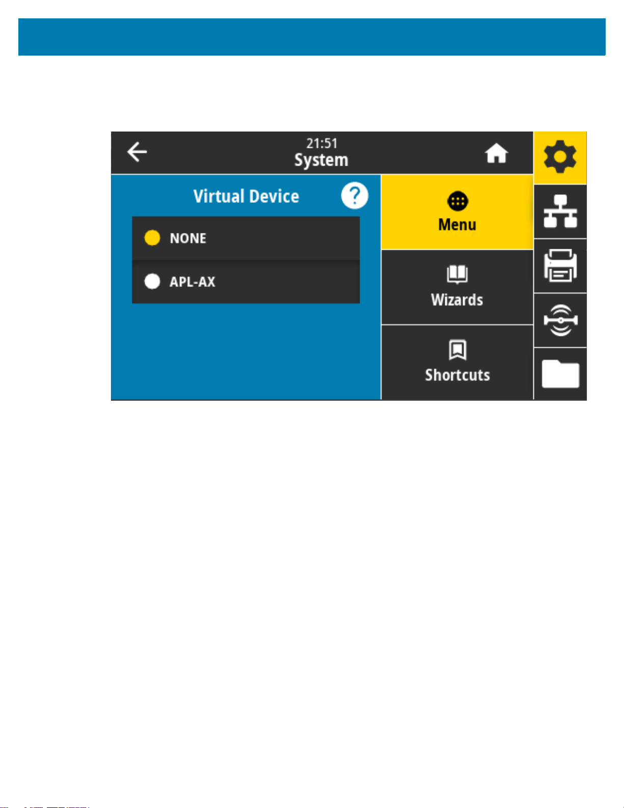
Color Touch Display and Controls
System > Program Language > Virtual Device
If any Virtual Device applications are installed on your printer, you may view or enable/disable them from
this user menu.
Accepted values: NONE or any Link-OS Virtual Device(s) will be in a list here.
78
Page 79
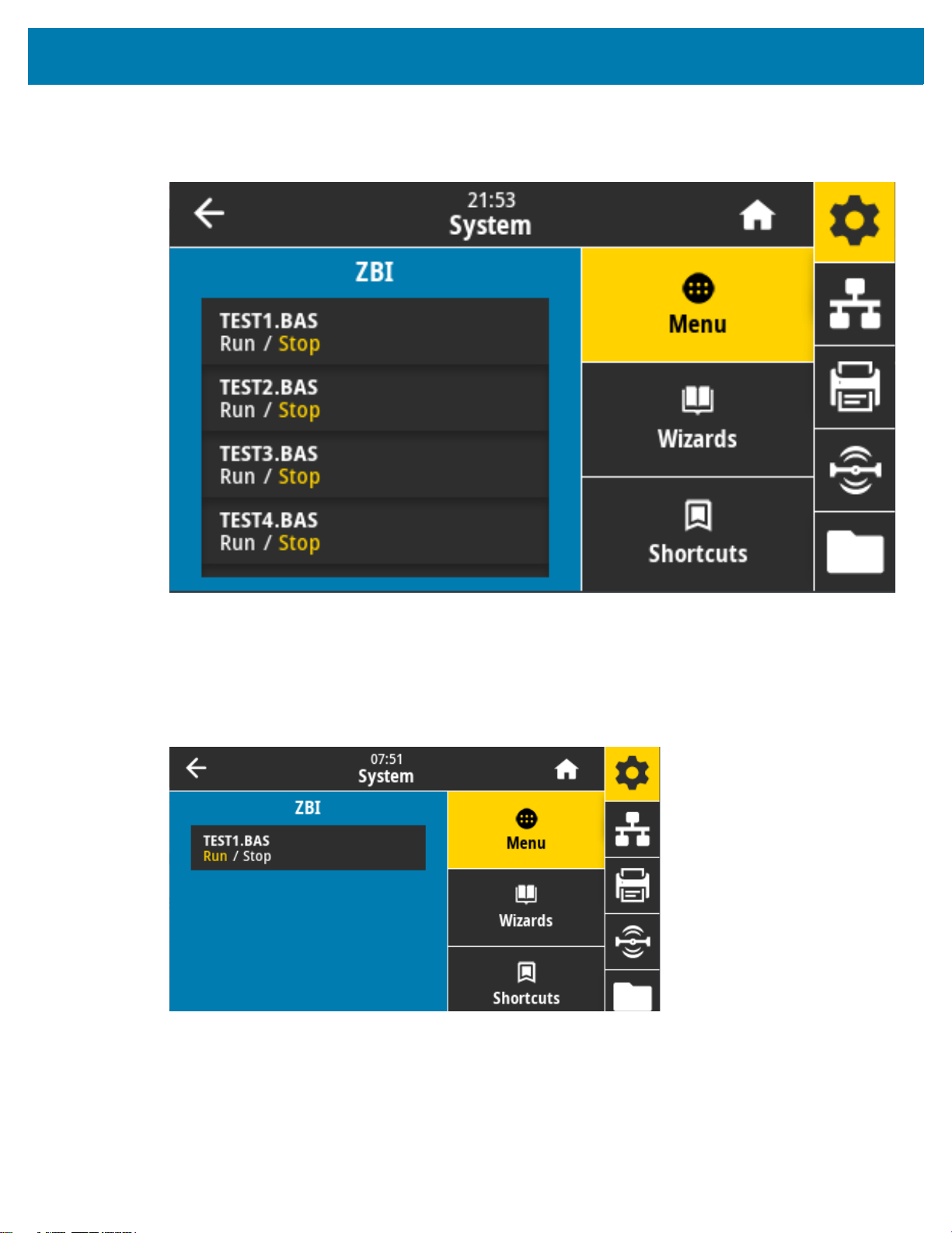
Color Touch Display and Controls
System > Program Language > ZBI
Zebra Basic Interpreter (ZBI 2.0 ™ ) is a programming option that may be purchased for your printer.
Zebra Basic Interpreter (ZBI 2.0™ ) is a programming option that may be purchased for your printer. If you
would like to purchase this option, contact your Zebra reseller for more information.
If ZBI programs have been downloaded to your printer, you may select one to run using this menu item. If
no program exists on your printer, NONE is listed.
When ZBI programs have been downloaded but none are running, the printer lists all available programs.
To run one of them, touch Run (highlighted in white) under the program name.
After a program is running, only that program is listed. Touch Stop (highlighted in white) to end the
program.
SGD command used: zbi.key (identifies if the ZBI 2.0 option is enabled or disabled on the printer)
79
Page 80

Color Touch Display and Controls
System > Settings > Display Time Format
Use this setting to select the time format used by the printer.
Accepted values: 12-Hour, 24-Hour
SGD command used: device.idle_display_value
80
Page 81

Color Touch Display and Controls
System > Settings > Password Level
Use this setting to select the level of password protection for user menu items.
Accepted values: Selected, All, None
Related ZPL command(s): ^KP (to change the printer password)
81
Page 82

Color Touch Display and Controls
System > Settings > Set Password
Set a new printer password for menu items protected by the previous parameter.
Accepted values: Numerals 0-9
The default printer password is 1234.
Related ZPL command(s): ^KP
82
Page 83

Color Touch Display and Controls
System > Settings > Power Up Action
Set the action for the printer to take during the power-up sequence.
Accepted values:
CALIBRATE—Adjusts sensor levels and thresholds, determines the label length, and feeds the media
to the next web.
FEED—Feeds the labels to the first registration point.
LENGTH—Determines the label length using current sensor values, and feeds the media to the next
web.
NO MOTION—Tells the printer not to move the media. You must manually ensure that the web is
positioned correctly, or press feed to position the next web.
SHORT CAL—Sets the media and web thresholds without adjusting sensor gain, determines the label
length, and feeds the media to the next web.
Related ZPL command(s): ^MF
SGD command used: ezpl.power_up_action
Printer web page: View and Modify Printer Settings > Calibration
83
Page 84

Color Touch Display and Controls
System > Settings > Head Close Action
Set the action for the printer to take when you close the printhead.
Accepted values:
CALIBRATE—Adjusts sensor levels and thresholds, determines the label length, and feeds the media
to the next web.
FEED—Feeds the labels to the first registration point.
LENGTH—Determines the label length using current sensor values, and feeds the media to the next
web.
NO MOTION—Tells the printer not to move the media. You must manually ensure that the web is
positioned correctly, or press feed to position the next web.
SHORT CAL—Sets the media and web thresholds without adjusting sensor gain, determines the label
length, and feeds the media to the next web.
Related ZPL command(s): ^MF
SGD command used: ezpl.head_close_action
Printer web page: View and Modify Printer Settings > Calibration
84
Page 85

Color Touch Display and Controls
System > Settings > Screen Calibration
Touch each crosshair to calibrate the screen.
85
Page 86

Color Touch Display and Controls
System > Settings > Restore Defaults
Restore specific printer, print server, and network settings back to the factory defaults.
Use care when loading defaults because you will need to reload all settings that you changed manually.
This menu item is available through two user menus with different default values for each.
Accepted values:
PRINTER—Restores all printer settings other than the network settings back to the factory defaults.
Use care when loading defaults because you will need to reload all settings that you changed manually.
NETWORK—Reinitializes the printer’s wired or wireless print server. With a wireless print server, the
printer also re-associates with your wireless network.
LAST SAVED—Loads settings from the last permanent save.
NO MOTION—Tells the printer not to move the media. You must manually ensure that the web is
positioned correctly, or press feed to position the next web.
SHORT CAL—Sets the media and web thresholds without adjusting sensor gain, determines the label
length, and feeds the media to the next web.
Related ZPL command(s):
PRINTER— ^JUF
NETWORK— ^JUN
LAST SAVED— ^JUR
Control panel key(s): Hold FEED + PAUSE during printer power-up to reset the printer parameters to
factory values.
Printer web page:
PRINTER—View and Modify Printer Settings > Restore Default Configuration
NETWORK—Print Server Settings > Reset Print Server
LAST SAVED—View and Modify Printer Settings > Restore Saved Configuration
86
Page 87

Color Touch Display and Controls
System > Settings > Print: System Settings
Prints a printer configuration report.
Related ZPL command(s): ~WC
Control panel key(s):
Hold CANCEL for 2 seconds during printer power-up.
Hold FEED + CANCEL for 2 seconds when the printer is in the Ready state.
Printer web page: View and Modify Printer Settings > Print Listings on Label
87
Page 88

Color Touch Display and Controls
System > Energy Saving > Energy Star
When Energy Star mode is enabled, the printer goes into a “sleep” mode after a timeout period, thereby
lowering power consumption. Press any button on the control panel to bring the printer back to an active
state.
Accepted values: ON, OFF
SGD command used:
power.energy_star.enable
power.energy_star_timeout
88
Page 89
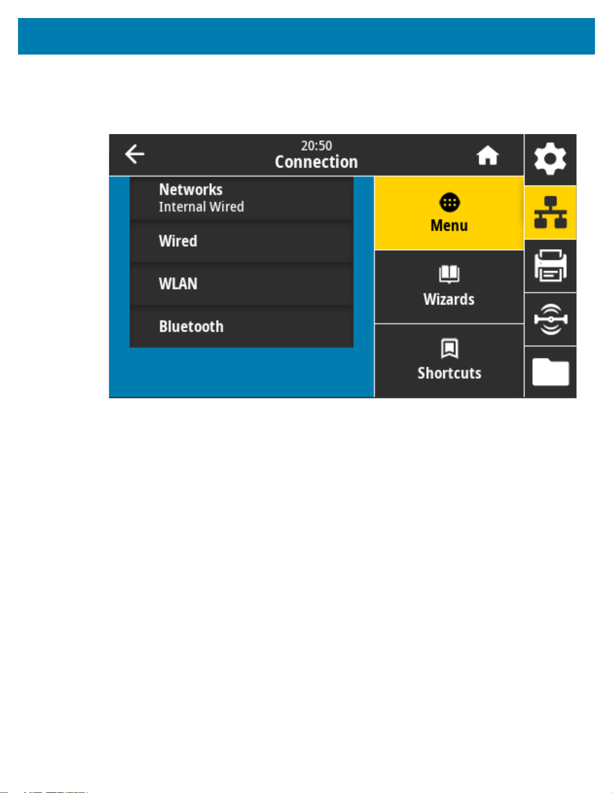
Connection Menu
Use this menu to set connection parameters for wired and wireless (Wi-Fi and Bluetooth) printer
communication.
Color Touch Display and Controls
89
Page 90

Color Touch Display and Controls
Connection > Networks > Reset Network
This option resets the wired or wireless print server and saves any changes that you made to any network
settings.
You must reset the print server to allow changes to the network settings to take effect.
Related ZPL command(s): ~WR
SGD command used: device.reset
Printer web page: Print Server Settings > Reset Print Server
90
Page 91

Color Touch Display and Controls
Connection > Networks > Primary Network
View or modify whether the wired or wireless print server is considered primary. You may select which one
is primary.
Accepted values: Wired, WLAN
Related ZPL command(s): ^NC
SGD command used: ip.primary_network
91
Page 92

Color Touch Display and Controls
Connection > Networks > IP Port
This printer setting refers to the internal wired print server's port number that the TCP print service is
listening on. Normal TCP communications from the host should be directed to this port.
SGD command used: internal_wired.ip.port
Printer web page: View and Modify Printer Settings > Network Communications Setup > TCP/IP Settings
92
Page 93

Color Touch Display and Controls
Connection > Networks > IP Alternate Port
This command sets the port number of the alternate TCP port.
Print servers supporting this command will monitor both the primary port and the alternate port for
connections at the same time.
SGD command used:
internal_wired.ip.port_alternate
wlan.ip.port_alternate
Printer web page: View and Modify Printer Settings > Network Communications Setup > TCP/IP Settings
93
Page 94

Color Touch Display and Controls
Connection > Networks > Print: Network Info
Prints the settings for any print server or Bluetooth device that is installed.
Related ZPL command(s): ~WL
Control panel key(s):
Hold CANCEL for 2 seconds during printer power-up.
Hold FEED + CANCEL for 2 seconds when the printer is in the Ready state.
Printer web page: View and Modify Printer Settings > Print Listings on Label
94
Page 95

Color Touch Display and Controls
Connection > Networks > Visibility Agent
When the printer is connected to a wired or wireless network, it will attempt to connect to Zebra’s Asset
Visibility Service via the Cloud-based Zebra Printer Connector using an encrypted,
certificate-authenticated web socket connection. The printer sends Discovery Data and Settings and Alerts
Data. Data printed via any label formats is NOT transmitted. To opt-out of this feature, disable this setting.
Accepted values: ON, OFF
SGD command used: weblink.zebra_connector.enable
Printer web page: View and Modify Printer Settings > Network Configuration > Cloud Connect Settings
NOTE: For more information, refer to the “Opting Out of the Asset Visibility Agent” application note at
zebra.com.
95
Page 96

Color Touch Display and Controls
Connection > Wired > Wired IP Protocol
This parameter indicates if the user (permanent) or the server (dynamic) selects the wired print server’s IP
address. When a dynamic option is chosen, this parameter tells the method(s) by which this print server
receives the IP address from the server.
You must reset the print server to allow changes to the network settings to take effect. Go to Connection >
Networks > Reset Network on page 90
Accepted values: ALL, GLEANING ONLY, RARP, BOOTP, DHCP, DHCP & BOOTP, PERMANENT
Related ZPL command(s): ^ND
SGD command used: internal_wired.ip.protocol
Printer web page: View and Modify Printer Settings > Network Communications Setup > TCP/IP Settings
96
Page 97

Color Touch Display and Controls
Connection > Wired > Wired IP Address
View and, if necessary, change the printer’s wired IP address.
To save changes to this setting, set Connection > Wired > Wired IP Protocol to PERMANENT, and then
reset the print server (go to Connection > Networks > Reset Network on page 90).
Accepted values: 000 to 255 for each field
Related ZPL command(s): ^ND
SGD command used: internal_wired.ip.addr
Printer web page: View and Modify Printer Settings > Network Communications Setup > TCP/IP Settings
97
Page 98

Color Touch Display and Controls
Connection > Wired > Wired Gateway
View and, if necessary, change the default wired gateway.
To save changes to this setting, set Connection > Wired > Wired IP Protocol to PERMANENT, and then
reset the print server (go to Connection > Networks > Reset Network on page 90).
Accepted values: 000 to 255 for each field
Related ZPL command(s): ^ND
SGD command used: internal_wired.ip.gateway
Printer web page: View and Modify Printer Settings > Network Communications Setup > TCP/IP Settings
98
Page 99

Color Touch Display and Controls
Connection > Wired > Wired Mac Address
View the Media Access Control (MAC) address of the wired print server. This value cannot be modified.
SGD command used: internal_wired.mac_addr
Printer web page: View and Modify Printer Settings > Network Communications Setup > TCP/IP Settings
99
Page 100

Color Touch Display and Controls
Connection > WLAN > WLAN IP Protocol
This parameter indicates if the user (permanent) or the server (dynamic) selects the wireless print server’s
IP address. When a dynamic option is chosen, this parameter tells the method(s) by which this print server
receives the IP address from the server.
You must reset the print server to allow changes to the network settings to take effect. Go to Connection >
Networks > Reset Network on page 90.
Accepted values: ALL, GLEANING ONLY, RARP, BOOTP, DHCP, DHCP & BOOTP, PERMANENT
Related ZPL command(s): ^ND
SGD command used: wlan.ip.protocol
Printer web page: View and Modify Printer Settings > Network Communications Setup > Wireless Setup
100
 Loading...