

Page 1
ZC100/300 Series
Card Printer
Mac Driver
User Guide
P1102718-001
Page 2

2
Page 3

Contents
Printer Properties ..............................................................................................................................................1
Device Info Tab .................................................................................................................................................2
Card Setup Tab ...............................................................................................................................................11
Device Information ................................................................................................................................2
Printer usage ........................................................................................................................................3
Security .................................................................................................................................................3
Media Info .............................................................................................................................................3
Tools .....................................................................................................................................................4
Sensors & Calibration ...............................................................................................................4
Cleaning ...................................................................................................................................8
Firmware...................................................................................................................................9
Printer Settings ...................................................................................................................................10
Card Options .......................................................................................................................................11
Printing Options ..................................................................................................................................12
Ribbon Info and Options .....................................................................................................................12
Front K Extraction ...................................................................................................................14
Back K Extraction ...................................................................................................................15
Front Overlay ..........................................................................................................................15
Back Overlay ..........................................................................................................................15
Half Panel ...........................................................................................................................................16
YMCKLL .............................................................................................................................................17
SDYMCKO ..........................................................................................................................................18
YMCPKO ............................................................................................................................................20
Encoding Tab ..................................................................................................................................................21
Image Optimizations Tab ................................................................................................................................22
Color Panel .........................................................................................................................................22
Black/Mono Panel ...............................................................................................................................23
About Tab ........................................................................................................................................................25
i
Page 4

ii
Page 5
Printer Properties
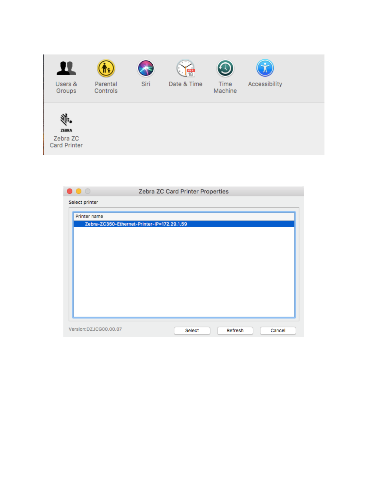
Type “Zebra” in the Unity Launcher (available in the top left corner of the screen by default or else use Window
Key).
An authentication dialog will appear to conrm launching the printer properties, click Yes to continue.
At the Select printer window, highlight the desired printer and click Select. Otherwise, click Cancel to exit.
1
Page 6
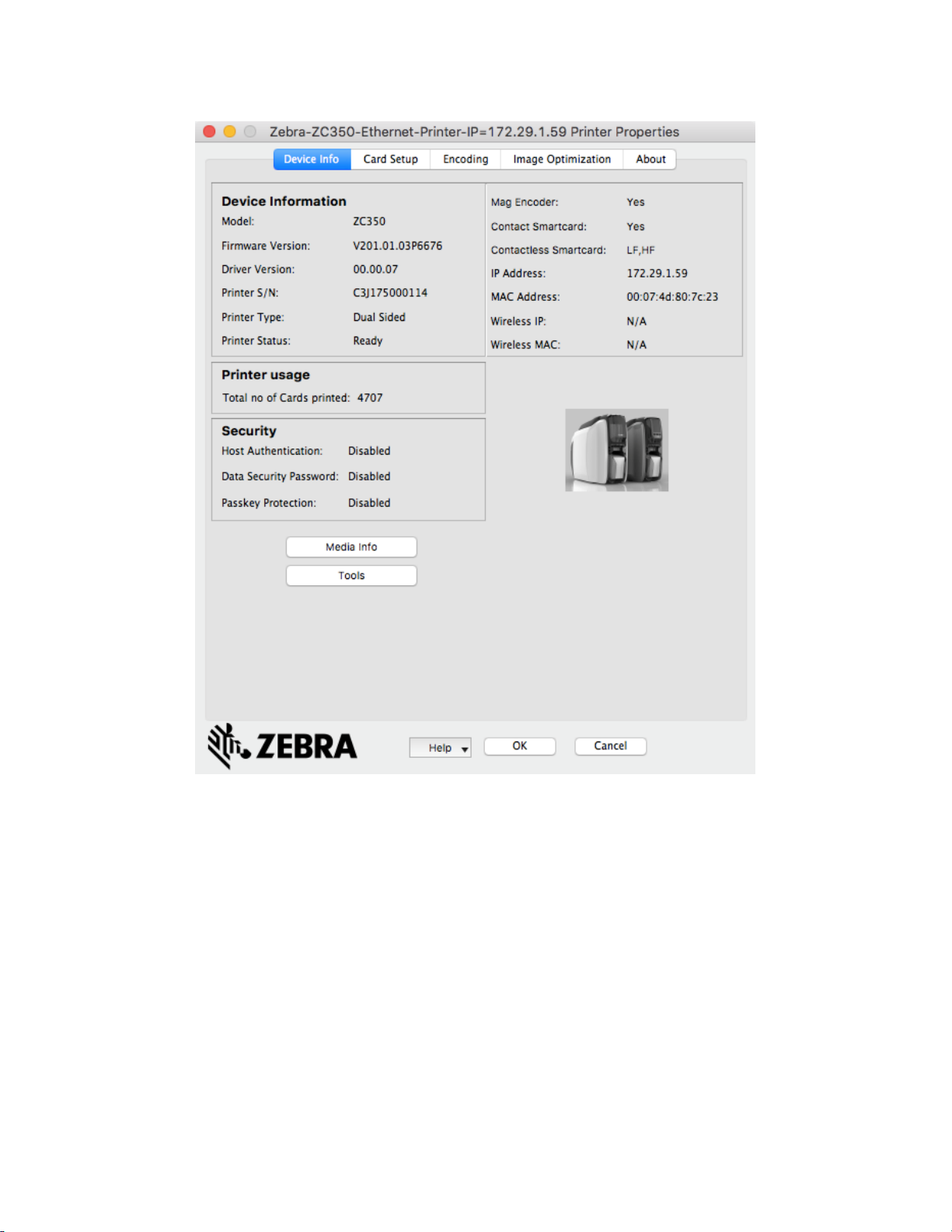
Device Info Tab
The Device Information tab provides device information, security status, and printer usage.
Device Information
Model – Shows the model name of the printer.
Firmware Version – Shows the version of rmware.
Driver Version – Shows the version of the installed driver.
Printer S/N – Shows the printer serial number.
Printer Type – Shows single-sided, or dual-sided.
Printer Status – Shows the status of the selected printer.
Mag Encoder – Shows if a Mag Encoder is installed or not.
Contact Smart Card – Shows if the contact smart card encoder is installed or not.
Contactless Smart Card – Shows the type of contactless smart card option installed.
IP Address – Shows the IP address.
2
Page 7
MAC Address – Shows the MAC address.
Wireless IP – Displays the wireless IP address
Wireless MAC – Shows the wireless MAC address.
Printer usage
Total no of Cards Printed – Shows the total number of cards printed for the lifetime of the printer.
Security
Host Authentication – Shows the status of the host authentication.
Data Security Password – Shows the status of the data security password.
Passkey Protection – Shows the status of the passkey protection.
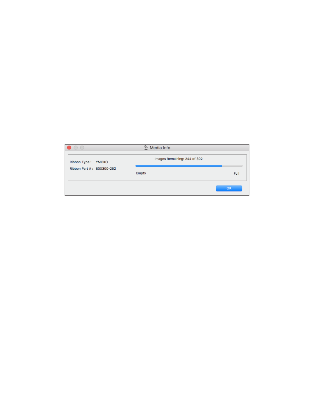
Media Info
The Media Info button takes you to the Media Info screen.
3
Page 8
Tools
The Tools application includes functions that are used for printer operation and / or maintenance. The Tools
application is divided into four tabs:
y Sensors & Calibration
y Cleaning
y Firmware
y Printer Settings
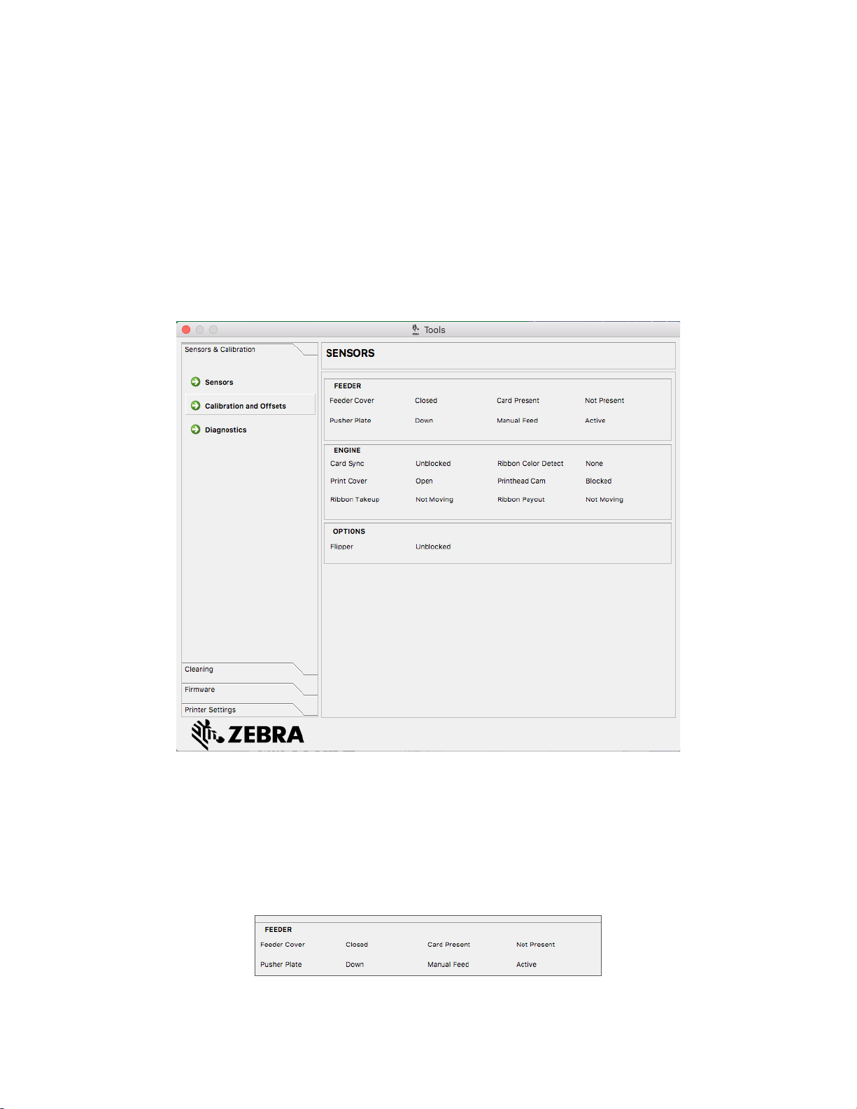
Sensors & Calibration
The Sensors & Calibration tab is divided into three sub-tabs:
y Sensors
y Calibration and Osets
y Diagnostics
The Sensors sub-tab is divided into three sections:
The Feeder section tracks the sensors in the feeder section of the printer and noties the user of the current status.
4
Page 9
The Engine section tracks the sensors in the main section of the printer and noties the user of the current status.
The Options section tracks the sensors in the installed options of the printer and noties the user of the current
status.
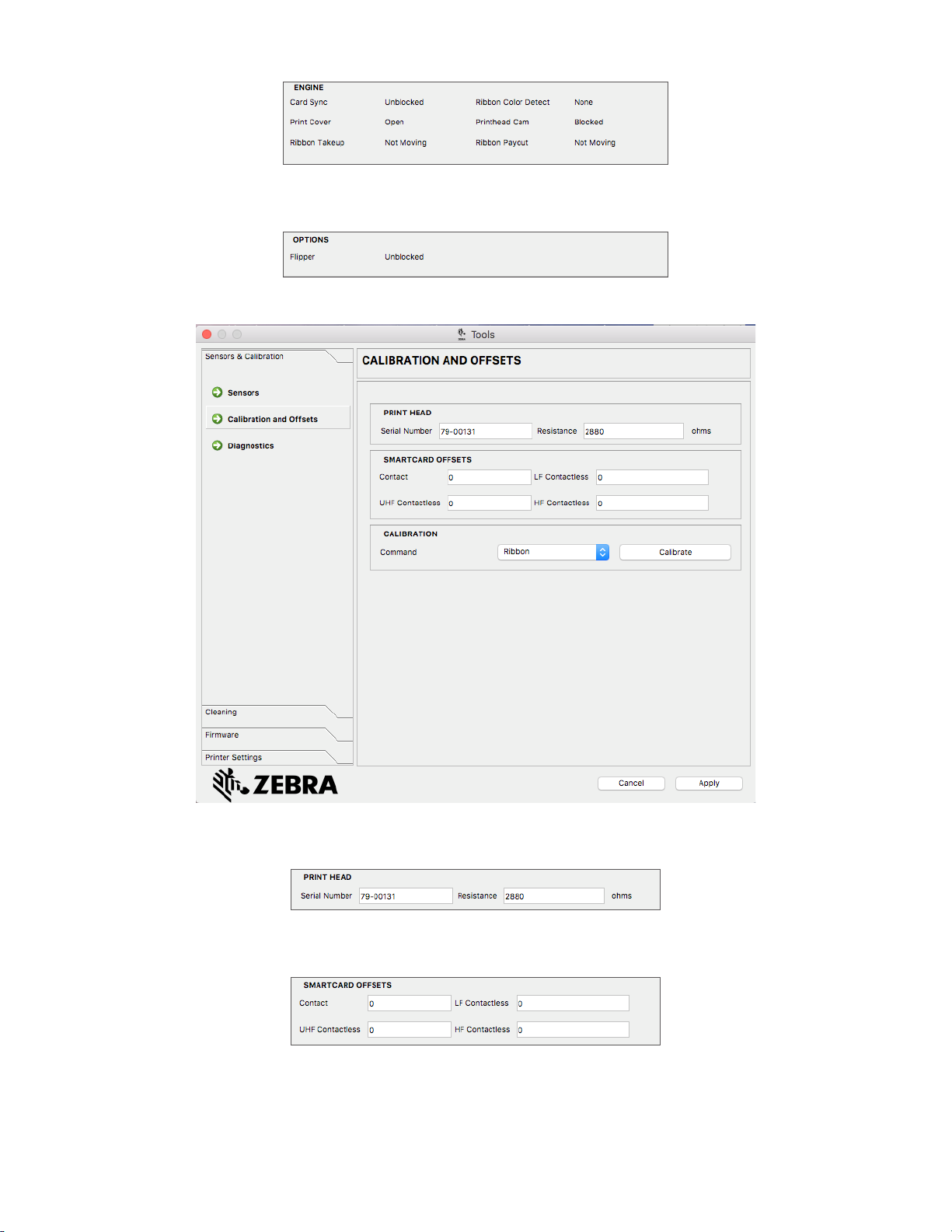
The Calibration and Osets sub-tab is divided into three sections:
The Printhead section tracks the serial number and resistance value of the currently installed printhead. Use this
section when installing a new printhead to enter new values.
The Smartcard Osets sections identies values for dierent smartcard types, and enables the user to change the
values.
5
Page 10

The Calibration section enables the user to calibrate certain sensors in the printer. This option can be used if a
particular sensor is suspected to not be working properly. Currently, the only sensor available to calibrate is the
Ribbon Detect Sensor.
The Diagnostics sub-tab is divided into seven sections:
The Motor section enables the user to activate the motors individually. Select the motor, the motor speed (if
applicable), and direction from the drop-down lists and click On. The motor will engage at the selected settings, click
O to disengage the motor.
WARNING • Do not engage the card feed motor with cards present in the input hopper or serious damage
may result.
Note • Each motor can be engaged in forward or reverse.
y The Card Feed motor can be engaged at speeds ranging from 0–2000 in increments of 100.
y The Card X motor can be engaged at speeds of 1–20 in increments of 1.
y The Ribbon motor can be engaged at a single speed only.
y The Head Lift motor can be engaged at speeds of 0–2000 in increments of 100.
y The Options motor can be engaged at speeds of 0–2000 in increments of 100.
6
Page 11

y The Flipper motor can be engaged at speeds of 0–2000 in increments of 100.
The Cam section is used to drive the lift cam for either the options module (if installed), or the printhead to be put
into preset positions.
The Transport section sends cards to dierent locations in the printer.
The Panel section is used to move the specied ribbon panel into the ready position. The drop-down menu contents
will vary depending on the ribbon installed.
The Rotate section is used to move the ipper (if installed) to dierent positions.
The Sensor section enables the user to turn dierent sensors on or o.
The Fan section turns the cooling fan(s) on or o. Currently, only the printhead fan is supported.
7
Page 12

Cleaning
The Cleaning sub-tab shows the user how many cards can be printed before the next cleaning is required.
Caution • PROTECT YOUR FACTORY WARRANTY!
The recommended cleaning procedures must be performed to maintain your factory warranty.
NEVER loosen, tighten, adjust, bend, etc., any part or cable inside the printer.
NEVER use a high pressure air compressor to remove particles in the printer.
The regular use of cleaning cards will clean and maintain important parts of your printer that cannot be reached:
including the printhead, the transport rollers, and the magnetic encoder station (optional).
Click Clean Now to initiate the cleaning process.
Step 1. At the prompt, remove the ribbon and cards from the printer.
Step 2. At the prompt, insert the cleaning card into the manual feed slot on the printer.
8
Page 13

Step 3. The cleaning process will begin.
Step 4. When the cleaning process has nished, remove the used cleaning card after it has been ejected.
Step 5. Replace the ribbon and cards.
The Cleaning Interval determines how many cards can be printed before cleaning is required; the recommended
(and default) value is 1,000 cards, and the maximum cleaning interval is 5,000 cards.
Important • Zebra does not recommend continued printing past the default cleaning interval as dust and
debris will collect on the print surfaces and result in poor print quality.
The Pre-Cleaning Count displays a warning in the driver control panel and the printer display (ZC100 not
applicable) showing the number of cards remaining before cleaning is due. The default value is twenty (20).
The Clean Printer Error Mode setting tells the printer to either Stop Printing when the cleaning notication occurs,
or to Allow Printing (default). If the user sets the error mode to Stop Printing, cleaning must be done before any
printing can continue. If the user sets the error mode to Allow Printing, printing can continue and cleaning can be
done at a later time.
Firmware
In the Firmware sub-tab, the user is shown the current rmware version, and can update to the latest rmware.
9
Page 14

Printer Settings
The Printer Settings allows you to change the various network conguration parameters (DHCP, SNMP, IP address,
Gateway, and Subnet mask). Note that the MAC address cannot be changed.
Turn DHCP o to set a static IP address.
Turn SNMP o if you do not want the printer to be discoverable on the network.
You cannot congure the settings for Wired Ethernet while you are connected via Ethernet; Ethernet settings are
congured while the printer is connected via USB. This is to prevent loss of communication.
10
Page 15

Card Setup Tab
The Card Setup tab enables the user to adjust selected card, print job parameters and print test cards.
Card Options
Card Source – Enables the user tell the printer where to take the card from.
Card Destination – Enables the user tell the printer where to send the nished cards.
Image Size – Enables the user to specify how much of the card to be printed on.
11
Page 16

Printing Options
TAKE-UP
SUPPLY
The Orientation drop-down list tells the printer to print in either Landscape (horizontal) or in Portrait (vertical)
depending on the design or the desired use of the card. Note that the printing orientation cannot be mixed; in other
words, you cannot print portrait on the front and landscape on the back.
The Print on both sides switch enables double-sided printing (applicable to dual-sided printers; ZC100 not
compatible).
The Rotate 180° drop-down list tells the printer to rotate the image on the card 180° (degrees). Use this option if you
want the images to be oriented the same way depending on how the card is ipped over.
The following selections are available from the Rotate 180° drop-down list:
y None – does not rotate the image(s).
y Front – only rotates the image on the front of the card.
y Back – only rotates the image on the back of the card.
y Both – rotates the image on both the front and the back of the card.
Print and Encode Same Side enables the user to encode a card and print an image on the mag stripe side. This
option is disabled when Print on Both Sides is enabled. To Print and Encode Same Side the printer must be dual
sided, Print on Both Sides must be set to No, and the printer must have a mag encoder.
Print Test Card enables the user to print a test card.
Ribbon Info and Options
Zebra card printers use ribbons (media) that come in two types: monochrome and color panels. Monochrome
ribbons are one continuous ribbon of a single color—typically black, but may be white, gold, or other single color
ribbons. With color panels, such as YMCKO (used for full color printing), each individual primary color (yellow,
magenta, cyan or YMC) along with black (K) and overlay or varnish (O) are laid out in sequence for one complete
card print process.
1 Panel Set
Y M C K O
SPOOL
Direction of Travel
The printer will recognize the type of print ribbon installed and display it in the Type eld. The available ribbon
combinations will be shown in the Combinations drop-down menu. Additionally, the Print on both sides and the
Print and Encode on Same Side settings will aect the available ribbon combinations. The Images Remaining
status bar indicates how many images can still be printed on the installed ribbon. This feature applies to ribbons
with panels and refers to the panel set (YMCK); monochrome ribbons do not apply. When a ribbon cartridge has 10
panel sets remaining, a Ribbon Low warning will be displayed.
SPOOL
12
Page 17

The following table shows the supported ribbons and their respective combinations:
Ribbon Print on Both Sides
O
YMCKO
On O
O
YMCKOK
On O
O
1/2YMCKO
On O YMCKO front / YMCKO back
O
1/2YMCKOKO
On O
O
KrO
On O KrO front / KrO back
O
KdO
On O KdO front / KdO back
K (Monochrome)
O
Includes all single
color ribbons
On O K front / K back
O
YMCPKO
On O
O
YMCKLL
On O
O
SDYMCKO
On O
Print and Encode Same
Side
Ribbon Combination
O YMCKO front
On YMCKO back
YMCO front / K back (default)
YMCKO front / YMCKO back
O YMCKO front
On YMCKO back
YMCKO front / K back (default)
YMCKO front / YMCKO back
O YMCKO front
On YMCKO back
O YMCKO front
On YMCKO back
YMCKO front / KO back (default)
YMCKO front / YMCKO back
O KrO front
On KrO back
O KdO front
On KdO back
O K front
On K back
O YMCPKO front
On YMCPKO back
YMCPO front / K back (default)
YMCPKO front / YMCPKO back
O YMCKLL front
On YMCKLL back
YMCLL front / K back (default)
YMCL front / KL back
YMCKLL front / YMCKLL back
O SDYMCKO front
On SDYMCKO back
SDYMCO front / K back (default)
SDYMCKO front / SDYMCKO back
The YMC panels in a color ribbon are used to create the color image. The ZC100 and ZC300 Series printers use 24
bit color data, color algorithms, and printhead management formulas to achieve 256 shades of color when printing a
full color image.
13
Page 18

The printer uses the K panel to print black elements on a color image (see “Black/Mono Panel” on page 23), or
barcodes and text. This is a resin panel, which means it cannot be used to print continuous tones of color. The K
panel can only print binary (pure on or o) images.
K is also used to denote monochrome ribbons, which are available in black, white, gold, silver, red, and blue.
Monochrome ribbons are also made of resin materials, which means they cannot be used to print continuous tones
of color, and can only print binary (pure on or o) images.
Kd denotes a black dye panel, which allows continuous shades of gray to be printed, and is ideally suited for photos
and graphics.
The O panel is an overlay which protects the dye panels against fading due to the eects of UV light and abrasion.
Overlay can also be applied to K resin to further protect text and barcodes against abrasion. This makes the KrO
ribbon useful in applications where card is swiped against a magnetic stripe reader and text or barcodes are printed
on the opposite side of the magnetic stripe.
The L panels in the YMCKLL ribbon enable long lasting color personalization of cards without the use of lamination.
The combination of two extra thick overlay panels adds four times more abrasion resistance to a color card,
compared to a standard YMCKO ribbon. The panels can also be used to print security features, which will appear as
a watermark on the card, and uoresce under UV light. Refer to “YMCKLL” on page 17 for more information.
The S (silver) panel in the SDYMCKO ribbon enables 3D-like visual eects to be created on the card. The silver is
a resin panel and it can be printed on the entire card for a metallic eect, or underneath a specic graphic element,
like a logo or text and then printer over with YMC to create a unique visual eect. Refer to “SDYMCKO” on page
18 for printing options.
The P (pearlescent) panel is a color shifting panel in the YMCPKO ribbon, enabling covert security elements to
the printed on the card, on demand. Images printed using the K and the P panels should ideally not overlap in the
design of the card. Refer to “YMCPKO” on page 20 for more printing options.
The Half-Panel (1/2) ribbons are used for printing full color images on a smaller area of a card (i.e., an ID photo).
The color panels are half the size of a normal color panel so waste is reduced and cards printed per ribbon is
greater; the K (black) and Overlay panels remain full size.
Front K Extraction
The Front K extraction button will become active when the ribbon type and ribbon combination has both YMC and K
on the same side (e.g., a YMCKO ribbon type and a YMCKO front ribbon combination).
Disable black extraction – does not use the K panel for any part of the image. This selection will have the eect of
rendering all black images as YMC composite.
Print YMC composite and K black – uses both the K panel and the Y, M, and C panels to print the portions of the
image that are identied as black. This selection will result in a dark, black image; but the edges will be smooth (due
to YMC printed under the K), not the sharp edges typically desired for a barcode.
Print all black data – uses only the K panel to print the portions of the image that are identied as being black.
14
Page 19

Back K Extraction
The Black Panel Options for the front and back are the same.
Front Overlay
Disable overlay – Overlay panel is not printed.
Full overlay – Overlay panel is printed over entire card.
Bitmap based Overlay – Tells the printer to print a solid image using the overlay, such as a logo, a shape, or text
that has been converted to a 1-bit per pixel bitmap. Click Browse, locate the le you wish to upload, and click Open.
Only 1-bit BMP and JPG les are supported.
y Rotate 180° is enabled when Bitmap based Overlay is selected.
y Invert is enabled when Bitmap based Overlay is selected, and reverses the dark and light colors--creating a
negative image.
Smartcard ISO – This option leaves a small area open over a smart card chip.
Magnetic Stripe – This option leaves an area open over the magnetic stripe.
The Intensity adjustment gives the user control over how dark or light the overlay panel is printed.
Back Overlay
The Overlay Panel Options for the front and back are the same.
15
Page 20

Half Panel
For single-sided printers and dual-sided printers with Print on Both Sides set to No the only ribbon combination for
Half Panel is YMCKO Front. For dual-sided printers with Print on Both Sides set to Yes the only ribbon combination
for Half Panel is YMCKO Front / YMCKO Back.
Note • The printable area for the color portion of the half-panel ribbon is 34 millimeters wide.
Typical YMCKO Ribbon
Y M C K O
Half Panel YMCKO Ribbon
Y M C K O
Auto (default) – detects the location of the color
portion of the image and starts color printing at
that location. In some cases, Auto detect may not
be suitable for your image (one of the other three
options may work better).
The Color Threshold slider is used to adjust
the sensitivity of the algorithm that determines
the starting location of the color panels. It is only
available with the Auto oset.
Custom – enables a manual oset setting.
The Oset Value slider is only available with the
Custom oset.
Note • Measurements are in pixels and start at the left, 1 pixel = 0.085 mm.
16
Page 21

Left Side – sets the print area to the left side of
the card.
Right Side – sets the print area to the right side of
the card.
YMCKLL
For single-sided printers and dual-sided printers with Print on Both Sides set to No the only ribbon combination for
the L Panel is YMCKLL front. For dual-sided printers with Print on Both Sides set to Yes there are three (3) ribbon
combination for the L Panel.
Disable L Panel – L panel is not printed.
Full L Panel – L panel is printed over entire card.
17
Page 22

Bitmap based L Panel – Tells the printer to print a solid image using the rst L panel, such as a logo, a shape, or
text that has been converted to a 1-bit per pixel bitmap. Click Browse, locate the le you wish to upload, and click
Open. Only 1-bit BMP and JPG les are supported.
When both L panels are printed on the same side of the card, and the bitmap option is enabled, the bitmap is only
printed using one of the L panels. This allows security features to be printed while maintaining a protective overlay.
y Rotate 180° is enabled when Bitmap based Overlay is selected.
y Invert is enabled when Bitmap based Overlay is selected, and reverses the dark and light colors--creating a
negative image.
Smart Card ISO – This option leaves a small area open over a smart card chip.
Magnetic Stripe – This option leaves an area open over the magnetic stripe.
Lastly, the Intensity slider can be used to increase or decrease the intensity of the L panel. In most cases this
should not be necessary; however, some card types may require more or less energy to print successfully with the L
panel.
SDYMCKO
For single-sided printers and dual -sided printers with Print on Both Sides set to No the only ribbon combination for
the Silver Panel is SDYMCKO Front. For dual-sided printers with Print on Both Sides set to Yes there are two (2)
ribbon combinations for the Silver Panel.
Disable Silver Panel – Silver panel is not printed.
Full Silver Panel – Silver panel is printed over entire card.
This enables the user to give the entire card a shiny look. Note that non-printed areas will appear silver, so this
combination is best suited for color images that completely cover the entire card.
18
Page 23

The user only needs to send one color image to the printer for single sided cards (i.e., SDYMCKO front), or two
images to the printer for dual-sided jobs (i.e., SDYMCO front / K back (rst image color, second image mono) or
SDYMCKO front / SDYMCKO back (both images color)).
Bitmap based Silver Panel – This enables the user to print the same image with the silver panel for every card,
such as for a logo or graphic.
This combination uses the same user-supplied bitmap for the silver panel for every card. Once the bitmap has been
selected, the user only needs to send one color image to the printer for single sided cards (i.e., SDYMCKO front), or
two images to the printer for dual sided jobs (i.e., SDYMCO front / K back (rst image color, second image mono) or
SDYMCKO front / SDYMCKO back (both images color)).
If the bitmap option is chosen, but no image is selected, the user must send the silver panel as part of the job. This
combination requires the user to send two images to the printer in order to print with the silver panel. The rst image
is for the silver panel, while the second image is for the color panels. If K is also on the same side (i.e., SDYMCKO
front), then K will be extracted from the second image if this feature is enabled. If K is on the back side of the card
(i.e., SDYMCO front / K back), then a third image is needed for the K panel—the rst image is still for the silver
panel and the second image is still for the color panels. When printing SDYMCKO front / SDYMCKO back, four
images need to be sent to the printer. The rst image is for the silver panel on the front, the second image is for the
color and K panels on the front, the third image is for the silver panel on the back, and the fourth image is for the
color and K panels on the back.
The front and back silver panel options can be set independently; however, this only applies to the
SDYMCKO front / SDYMCKO back ribbon combination.
Lastly, the Intensity slider can be used to increase or decrease the intensity of the silver panel. In most cases this
should not be necessary; however, some card types may require more or less energy to print successfully with the
silver panel.
19
Page 24

YMCPKO
For single-sided printers and dual-sided printers with Print on Both Sides set to No, the only ribbon combination for
the Pearlescent Panel is YMCKPO Front. For dual-sided printers with Print on Both Sides set to Yes, there are two
(2) ribbon combinations.
Disable Pearlescent – Pearlescent panel is not printed.
Bitmap based Pearlescent Panel – This enables the user to print the same image with the pearlescent panel for
every card, such as a logo or graphic.
This combination uses the same user-supplied bitmap for the pearlescent panel for every card. Once the bitmap
has been selected, the user only needs to send one color image to the printer for single sided cards (i.e., YMCPKO
front), or two images to the printer for dual sided jobs (i.e., YMCPO front / K back (rst image color, second image
mono) or YMCPKO front / YMCPKO back (both images color)).
If the bitmap option is chosen, but no image is selected, the user must send the pearlescent panel as part of the job.
This combination requires the user to send two images to the printer in order to print with the pearlescent panel. The
rst image is for the color panels, and the second image is for the pearlescent panel. If K is also on the same side
(i.e., YMCPKO front), then K will be extracted from the rst image if this feature is enabled. If K is on the back side
of the card (i.e., YMCPO front / K back), then a third image needs to be sent to the printer for the K panel. The rst
image is still for the color panels and the second image is still for the pearlescent panel. When printing YMCPKO
front / YMCPKO back, four images need to be sent to the printer. The rst image is for the color and K panels on the
front, the second image is for the pearlescent on the front, the third image is for the color and K panels on the back,
and the fourth image is for the pearlescent panel on the back.
y Rotate 180° is enabled when Bitmap based Overlay is selected.
y Invert is enabled when Bitmap based Overlay is selected, and reverses the dark and light colors--creating a
negative image.
Note • The front and back pearlescent panel options can be set independently; however, this only applies
to the YMCPKO front / YMCPKO back ribbon combination.
20
Page 25

Encoding Tab
The Encoding options enable the user to set various magnetic encoding options.
Disable Magnetic Encoding – Prevents the printer from encoding a card, whether the job has magnetic encoding
data in it or not.
Encode Only – Disables printing, whether the job has an image to be printed or not.
Magnetic encoder verication ON – Veries the data that is written to the card before declaring the encoding
action to be successful.
Coercivity – Selections are High and Low to match the card type.
Magnetic encoding type – Selections are ISO (default), AAMVA, CUSTOM, and BINARY.
Use Hex format to encode tracks – Select this option to encode the tracks using hexadecimal format.
21
Page 26

Image Optimizations Tab
Color Panel
The Color Panel selection enables the user to adjust how the color images print—it does not aect the color images.
Sharpening Filter – Options are None, Low, Normal (default), and High. Adjustments are not reected in the
preview image.
Brightness and Contrast – Adjustments range from -25 to +25, default = 0. Changes are reected in the preview
image.
By default, the image le is automatically sharpened; i.e., edges are enhanced within the image. If sharpening has
already been done, this function can be turned o (None). The Low and High options are available if additional
sharpening adjustment is required.
Preheat – Adjustment ranges from -50 to 50, default = 0. Increasing the preheat value will darken up edges of fonts,
ne lines, and color edges that are against a white or very near white background.
In some cases, increasing the preheat value too much can cause the white or near white images to print with a light
color cast. Increasing the preheat might also improve color-to-color mis-registration that may occur.
Intensity – Adjustments for Yellow, Magenta, and Cyan range from 80 to 120.
22
Page 27

By default, the Maintain YMC ratio checkbox is selected; so all three sliders move at the same time. With the
checkbox unselected, the sliders move independently. Note that by moving the sliders independently the tones of
the image will shift.
Intensity can be used to lighten or darken the entire printed color image. It can be used to eliminate ribbon wrinkling
or ribbon sticking/ripping in hot or humid environmental conditions.
Note • Note that the Intensity setting has no eect on the preview image but is applied to the image during
the printing process. These adjustments remain set until changed.
Black/Mono Panel
The Black/Mono Panel tab displays two identical adjustment sections (Front and Back) to optimize black panel
printing for the type of image being printed. The front side and back side options are enabled based on the
availability of K panel in the ribbon combination or the presence of a monochrome ribbon.
Optimization – Enables presets for optimal printing:
Text – Optimizes black panel printing to produce crisp, clear text.
Mixed – Optimizes black panel printing for both text and barcodes, or text and pictures, or other combinations.
Barcode optimizes black panel printing for sharp barcodes that are easily read by scanners.
23
Page 28

Monochrome Conversion – Used to convert continuous tone 8-bit-per-pixel RGB or gray image content into
binary1-bit-per-pixel content, as monochrome panels can only print binary (pure on or o) images.
Threshold – This is the simplest method for converting from 8 bits per pixel to 1 bit
per pixel. For example, the input pixel can be a value from 0 to 255. If the threshold is
128, any pixel from 0 to 128 becomes full on (1); and any pixel that is higher than 128
becomes full o (0). This mode works best for text, barcodes, line art, logos -- everything
except continuous-tone pictures. Use the Threshold slider to set the desired value.
Diusion – Dither diusion is used primarily where you have a full color (RGB image with
8 bits per pixel) or full gray (single color but still 8 bits per pixel) that you need to print with
binary printing (can only print full-on or full-o; i.e., 1 bit per pixel). Typically preferred over
halftoning for most images. Use the brightness and contrast sliders to adjust the levels to
the desired output.
Halftone – prints the bitmap image as a 6 x 6 halftone image, which simulates continuous
tone imagery through the use of dots, varying either in size or in spacing.
The conversion option selected determines which of the controls is enabled; i.e., selecting Threshold enables the
Threshold, Preheat, and Intensity controls.
Threshold – Sets the transition point between black (0) and white (255); i.e., pixel values less than the threshold
value would be black, and pixel values greater than the threshold value would be white. Default is 128.
Brightness – Controls overall the brightness of the image. Move the slider to the right to lighten the image or to the
left to darken the image.
Contrast – Controls the dierence between the light and dark areas of the image. Move the slider to the right to
increase the contrast and vice versa.
Preheat – Aects the edges of the printed image. Adjustments range from -50 to +50, default = 0.
Intensity – Adjusts the lightness or darkness of the image. Adjustments range from 80 to 120.
24
Page 29

About Tab
The About tab shows the driver version, the supported operating systems, and the copyright
25
Page 30

26
 Loading...