

Page 1
ZC100/300 Series
Service Manual
P1094921-001
Page 2

Copyright
© 2018 ZIH Corp. and/or its aliates. All rights reserved. ZEBRA and the stylized Zebra head are trademarks of ZIH
Corp., registered in many jurisdictions worldwide. All other trademarks are the property of their respective owners.
COPYRIGHTS & TRADEMARKS: For complete copyright and trademark information, go to: www.zebra.com/copyright
WARRANTY: For complete warranty information, go to: www.zebra.com/warranty
END USER LICENSE AGREEMENT: For complete EULA information, go to: www.zebra.com/eula
Terms of Use
Proprietary Statement This manual contains proprietary information of Zebra Technologies Corporation and its
subsidiaries (“Zebra Technologies”). It is intended solely for the information and use of parties operating and maintaining
the equipment described herein. Such proprietary information may not be used, reproduced, or disclosed to any other
parties for any other purpose without the express, written permission of Zebra Technologies.
Product Improvements Continuous improvement of products is a policy of Zebra Technologies. All specications and
designs are subject to change without notice.
Liability Disclaimer Zebra Technologies takes steps to ensure that its published Engineering specications and manuals
are correct; however, errors do occur. Zebra Technologies reserves the right to correct any such errors and disclaims
liability resulting therefrom.
Limitation of Liability In no event shall Zebra Technologies or anyone else involved in the creation, production, or
delivery of the accompanying product (including hardware and software) be liable for any damages whatsoever (including,
without limitation, consequential damages including loss of business prots, business interruption, or loss of business
information) arising out of the use of, the results of use of, or inability to use such product, even if Zebra Technologies has
been advised of the possibility of such damages. Some jurisdictions do not allow the exclusion or limitation of incidental or
consequential damages, so the above limitation or exclusion may not apply to you.
Page 3

Contents
Introduction ....................................................................................................................................................................1
About This Manual......................................................................................................................................................1
About the Printer ........................................................................................................................................................1
Replacement Procedures ..............................................................................................................................................3
Introduction .................................................................................................................................................................3
Required Tools and Supplies ......................................................................................................................................3
Removal Sequence ....................................................................................................................................................4
Procedures .................................................................................................................................................................5
Left Side Cover ...........................................................................................................................................................5
Right Side Cover ........................................................................................................................................................7
Rear Cover .................................................................................................................................................................9
Bottom Cover ...........................................................................................................................................................11
Left Side Filler Panel ................................................................................................................................................13
Right Side Filler Panel ..............................................................................................................................................14
Main Logic Board .....................................................................................................................................................15
Preparation ...............................................................................................................................................................15
Printhead ..................................................................................................................................................................19
Installation ................................................................................................................................................................19
Printhead Cable ........................................................................................................................................................21
Printhead Fan ...........................................................................................................................................................25
Dual-Sided Module ...................................................................................................................................................26
Dual-Sided Module Enclosure ..................................................................................................................................31
Wi-Fi Module ............................................................................................................................................................33
Feeder Assembly ......................................................................................................................................................36
i
Page 4

Contents
Feeder Front Bezel ...................................................................................................................................................38
Output Hopper Doors ...............................................................................................................................................40
Power Button ............................................................................................................................................................42
LED PCBA ................................................................................................................................................................43
Rear Deck ................................................................................................................................................................44
Rear Deck Encoder Module .....................................................................................................................................46
Ribbon Color Detect Sensor Assembly ....................................................................................................................49
Removal ...................................................................................................................................................................49
Card Detect Sensor Assembly .................................................................................................................................52
Front Deck Assembly ...............................................................................................................................................54
Top Cover Assembly .................................................................................................................................................55
Top Cover Dampener ...............................................................................................................................................56
Manual Advance Wheel ............................................................................................................................................57
Ribbon Drive Assembly ............................................................................................................................................59
Card Entry/Exit Module ............................................................................................................................................61
Tri-Sensor PCBA ......................................................................................................................................................63
Cam Position Sensor PCBA .....................................................................................................................................65
Lift Cam Motor ..........................................................................................................................................................67
Platen Drive Motor ....................................................................................................................................................68
Transport Rollers ......................................................................................................................................................69
Static Brush ..............................................................................................................................................................72
Feet ..........................................................................................................................................................................74
Troubleshooting ...........................................................................................................................................................75
Introduction ...............................................................................................................................................................75
Troubleshooting Table ..............................................................................................................................................75
Identifying Print Quality Issues .................................................................................................................................79
Color Accuracy .........................................................................................................................................................79
Dirt and Debris .........................................................................................................................................................79
Image Placement .....................................................................................................................................................79
Smear .......................................................................................................................................................................79
Black Extraction ........................................................................................................................................................79
Ribbon Wrinkle ............................................................................................................................................................79
ii
Page 5

Contents
Mis-registration ............................................................................................................................................................80
Ethernet Indicators—Detail..........................................................................................................................................80
Link/Activity Indicator (Green) .....................................................................................................................................80
Speed Indicator (Orange) ............................................................................................................................................80
Ribbon Repair..............................................................................................................................................................81
iii
Page 6

iv
Page 7

Introduction
About This Manual
This manual provides service and troubleshooting instructions for the ZC100, ZC150, ZC300, and ZC350 printers,
and their respective factory-installed options. Unless otherwise noted, instructions are identical for all printers.
About the Printer
The ZC100 Series and the ZC300 series printers provide full color dye sublimation or monochrome thermal transfer
printing on standard CR70 (2.051” x 3.303”) and CR80 (2.125” x 3.375”) PVC or PVC composite 10- to 40-mil cards.
The integrated card feeder and ipper minimizes printer size while maximizing performance. Zebra ribbon cartridges
have an integrated card cleaning roller for easy ribbon changing or replacement. A variety of options (some of which
can be factory-installed or eld-installed as upgrades) are available.
1
Page 8

2
Page 9
Replacement Procedures
Introduction
The following sections describe removing both major assemblies and—where applicable—sub-assemblies and/or
components that are considered replaceable.
Prior to any removal procedure, remove any ribbon and all cards in the printer
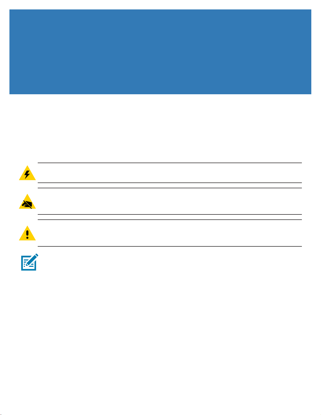
Electric Shock • Before performing any of the procedures in this section, set the printer power to OFF (O)
and disconnect the power cord.
Electrostatic Discharge • This replacement procedure must be performed at a static-free work station
or other suitable environment; an anti-static wrist strap must be worn and properly terminated, or other
appropriate protection must be used.
Caution • Before beginning any of the steps that follow, read completely through this procedure. If you do
not have the specied tools, or if any step(s) seem beyond your skill or experience level, do not attempt the
procedure. You may cause additional damage to the printer.
Note • Some of the photographs in this section may show additional parts removed in addition to removals
for the process being described.
Required Tools and Supplies
The following list species the tools required to perform the replacement procedures described in this section.
Naturally, not all tools are required for a particular procedure; specic tools are called out in each step as
appropriate.
y Nylon Pry Tool (two or more for certain procedures)
y TORX T10 Driver
y Flathead Screwdriver
y 5 mm E-Ring Clip Tool
y Rubbing Alcohol
y Lint-free Cloth or Wipes
y Gloves (for handling the LCD as necessary)
3
Page 10
Replacement Procedures
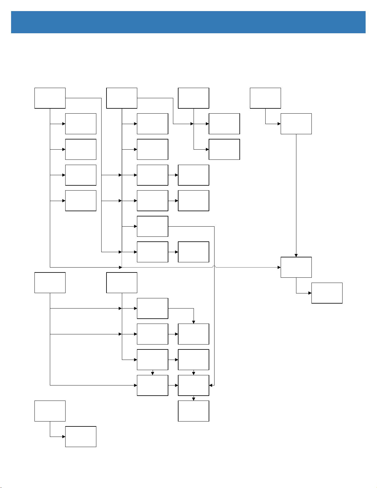
Removal Sequence
The following gures show the recommended removal sequence. For each item, follow the diagram upward to see
what must be removed for access. For example: to remove the LED PCBA, remove the left- and right-side covers,
then remove the feeder front bezel.
LeftSide
Cover
LeftSideFiller
Panel
RibbonDrive
Assembly
Tri‐Sensor
PCBA
CamPosition
SensorPCBA
PlatenDrive
Motor
RightSide
Cover
RightSide
FillerPanel
Wi‐FiModule
Manual
Advance
Wheel
Feeder
Module
TopCover
Assembly
CardEntry/
ExitModule
FeederFront
Bezel
Printhead
LCDPCBA
TopCover
Dampener
LEDPCBA
PrintheadFan
Printhead
Cable
RearPanel
BottomPanel
MainLogic
Board
LiftCam
Motor
Flipper
Module
Flipper
Enclosure
RearDeck
RearDeck
Encoder
Module
Ribbon
DetectSensor
Assembly
CardDetect
Sensor
Assembly
RearPlaten
Roller
NipRoller
Assembly
FrontDeck
FrontPlaten
Rollers
4
Page 11
Procedures
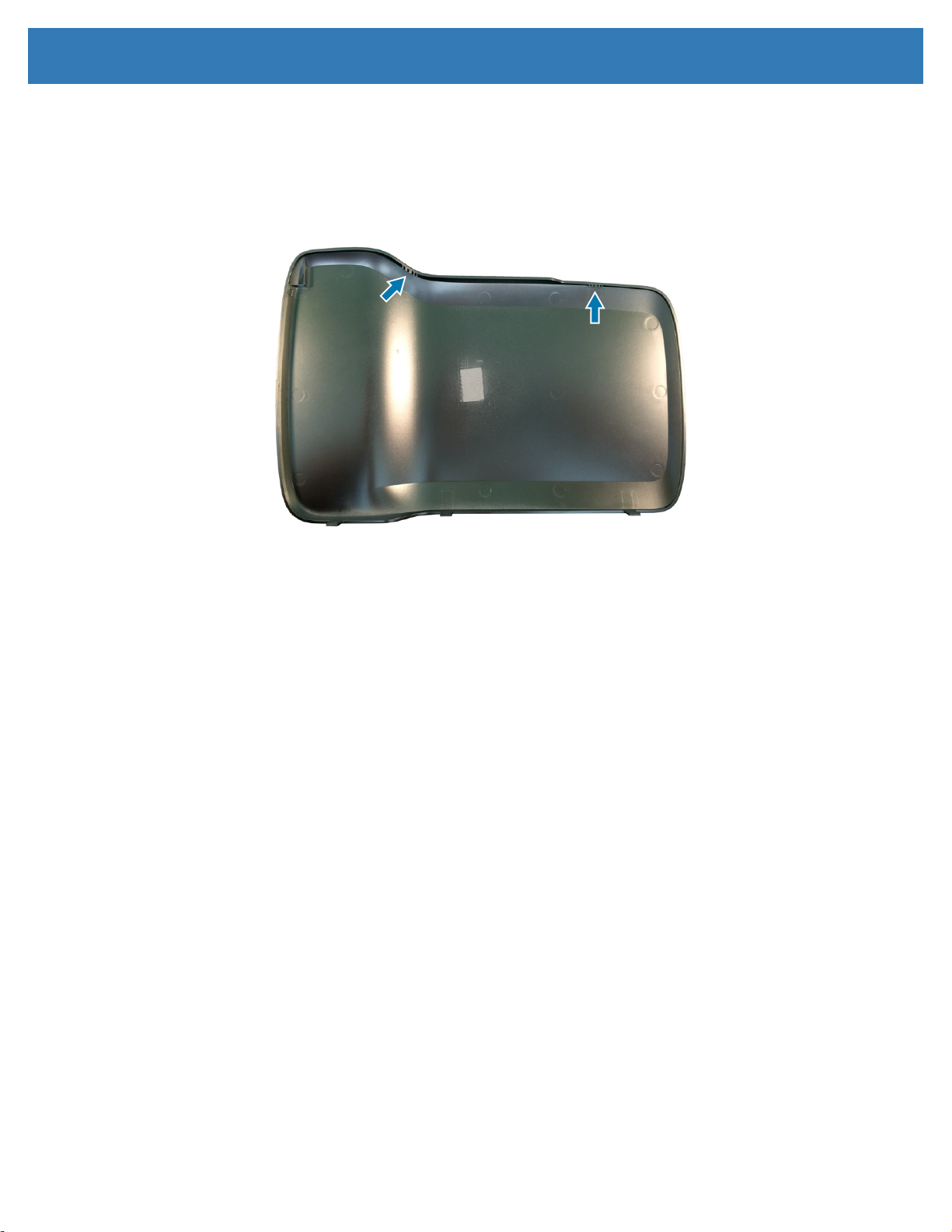
Left Side Cover
Removal
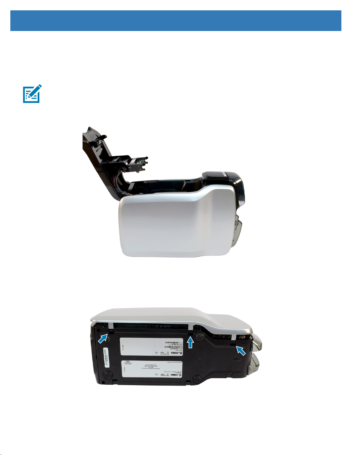
Note • Before placing the printer on its side cover, place a towel or cloth on the work surface to avoid
scratching the side cover.
Step 1. Open the top cover.
Replacement Procedures
Step 2. Turn the printer onto its right side.
Step 3. Using a nylon pry tool, release the three locking tabs securing the left side cover to the printer.
Step 4. Set the printer upright.
Step 5. Lift the left side cover from the printer.
5
Page 12
Replacement Procedures
Installation
Step 1. Open the top cover.
Step 2. Hang the left side cover onto the printer frame using the mounting tabs.
Step 3. Push the bottom of the cover onto the printer frame until the tabs lock into place.
Step 4. Close the top cover.
6
Page 13
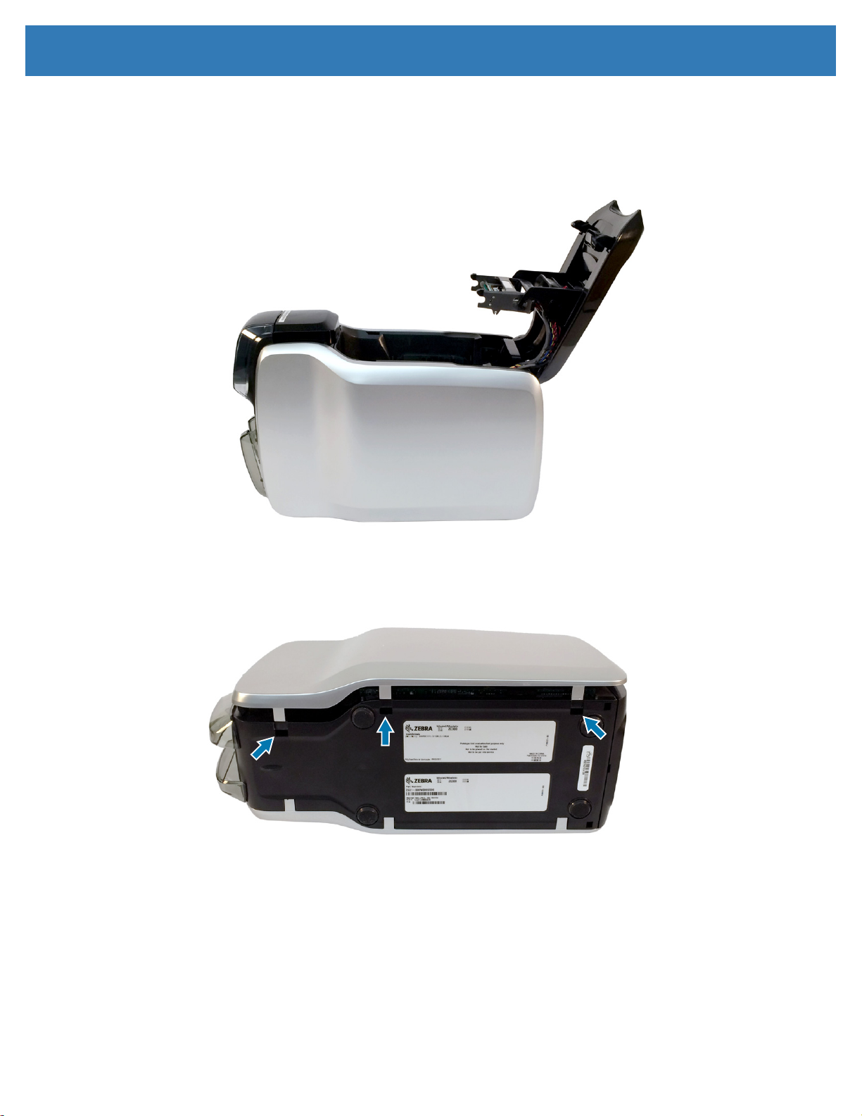
Right Side Cover
Removal
Step 1. Open the top cover.
Replacement Procedures
Step 2. Turn the printer onto its left side.
Step 3. Using a nylon pry tool, release the three locking tabs securing the right side cover to the printer.
Step 4. Lift the right side cover from the printer.
7
Page 14
Replacement Procedures
Installation
Step 1. Open the top cover.
Step 2. Hang the right side cover onto the printer frame using the mounting tabs.
Step 3. Push the bottom of the cover onto the printer frame until the tabs lock into place.
Step 4. Close the top cover.
8
Page 15
Replacement Procedures
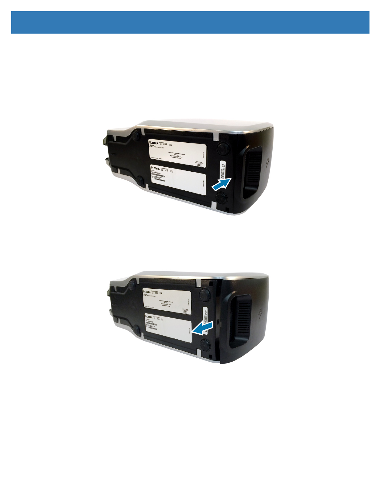
Rear Cover
Removal
Step 1. Place the printer on its side.
Step 2. Using a nylon pry tool, gently pry the rear cover at the slot at the bottom.
Step 3. Once unlocked, slide the rear panel downward.
9
Page 16
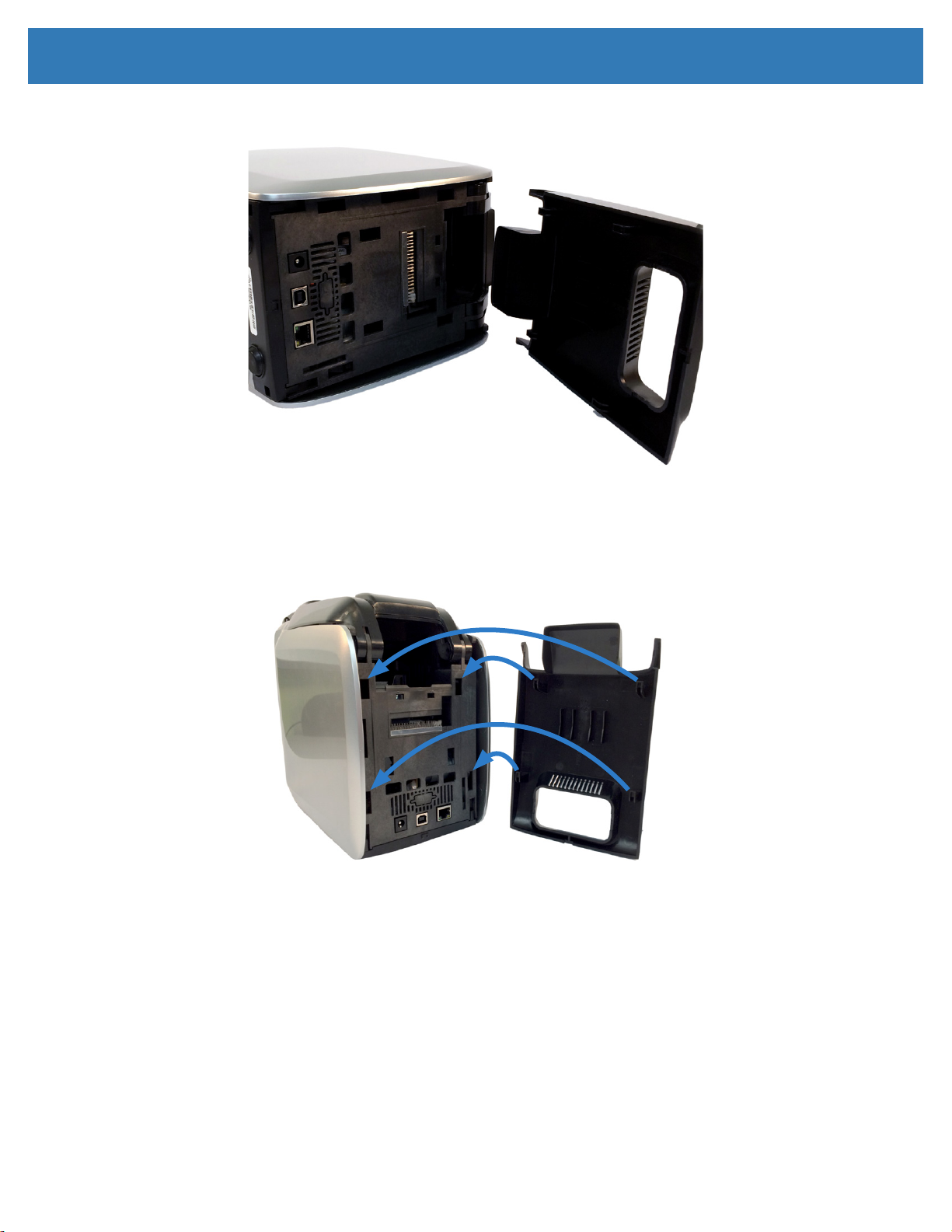
Step 4. Remove the rear panel.
Replacement Procedures
Installation
Step 1. Place the rear cover tabs into the respective mounting holes on the printer frame.
Step 2. Slide the rear cover upward until the rear cover locks into place.
10
Page 17
Replacement Procedures
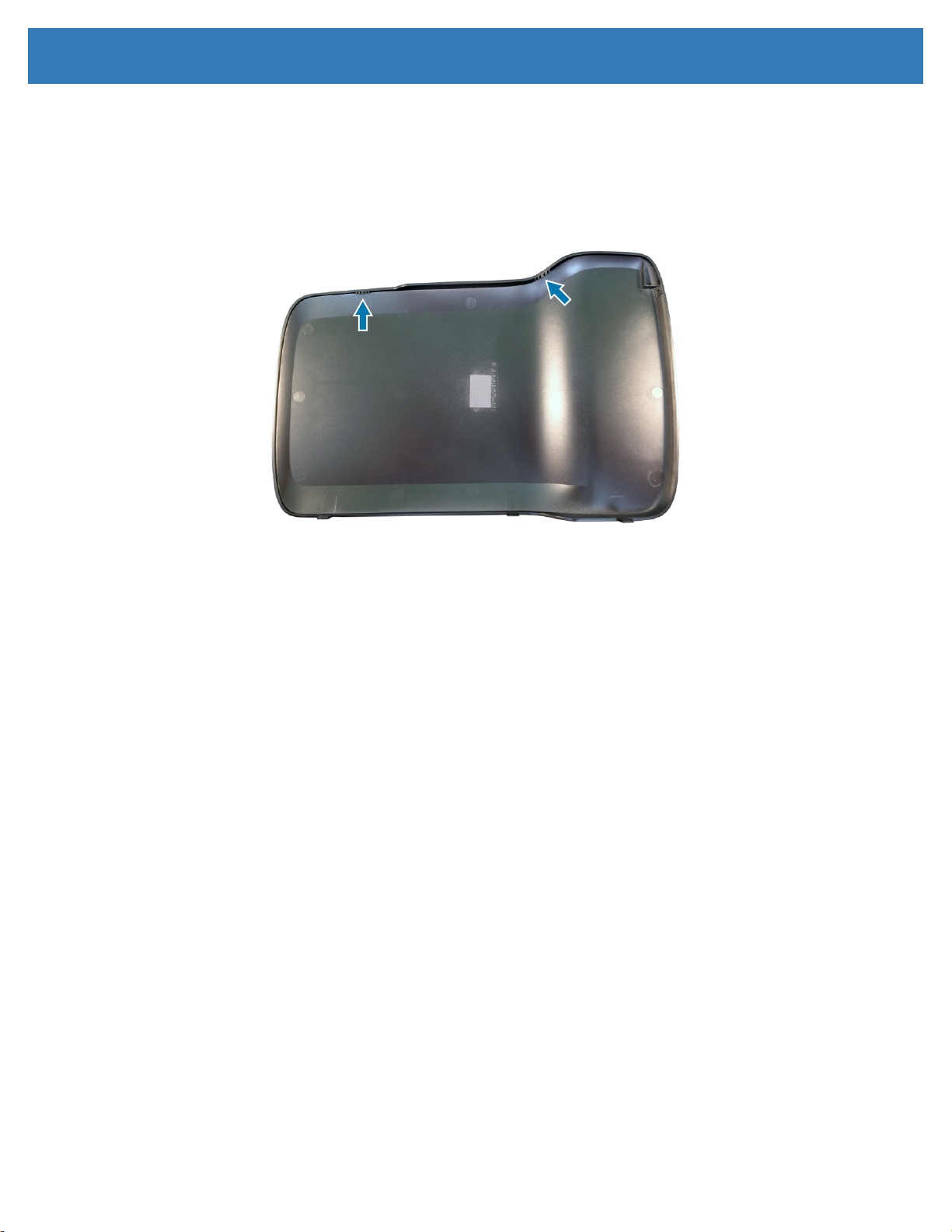
Bottom Cover
Note • This procedure is for reference only, there is no replacement kit for the bottom cover.
Removal
Step 1. Remove the left side cover (page 5).
Step 2. Remove the right side cover (page 7).
Step 3. Remove the rear cover (page 9).
Step 4. Using a nylon pry tool, release the locking tabs securing the bottom cover to the printer frame.
RIGHT
LEFT
Step 5. Slide bottom cover to the rear to release it from the printer frame.
Step 6. Remove the bottom cover.
11
Page 18
Replacement Procedures
Installation
Step 1. Place the bottom cover tabs into the respective mounting holes on the printer frame.
Step 2. While securing the bottom cover, open the output hopper doors to avoid interference.
Step 3. Push the bottom cover onto the printer frame until the tabs lock into place.
12
Page 19
Replacement Procedures
Left Side Filler Panel
Removal
Step 1. Open the top cover.
Step 2. Push down on the top of the ller panel to release the locking tabs from the printer frame.
Step 3. Remove the ller panel.
Installation
Step 1. Insert the bottom tab into its respective mounting hole on the printer frame.
Step 2. Push the ller panel into place until the tabs lock into place.
Step 3. Close the top cover.
13
Page 20
Replacement Procedures
Right Side Filler Panel
Removal
Step 1. Open the top cover.
Step 2. Push down on the top of the ller panel to release the locking tabs from the printer frame.
Step 3. Remove the ller panel.
Installation
Step 1. Insert the bottom tab into its respective mounting hole on the printer frame.
Step 2. Push the ller panel into place until the tabs lock into place.
Step 3. Close the top cover.
14
Page 21
Replacement Procedures
Main Logic Board
Electrostatic Discharge • This replacement procedure must be performed at a static-free work station
or other suitable environment; an anti-static wrist strap must be worn and properly terminated, or other
appropriate protection must be used.
Important • A conguration le, NVM_bkup_< printer serial number >.xml, is saved when the driver and
printer are rst installed. If the Main PCBA is not functional, you can use that le to restore the printer
settings.
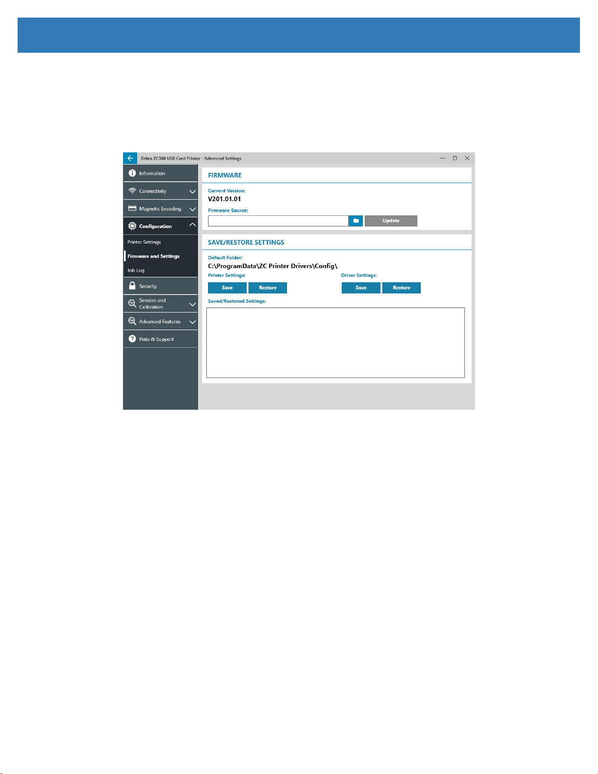
Preparation
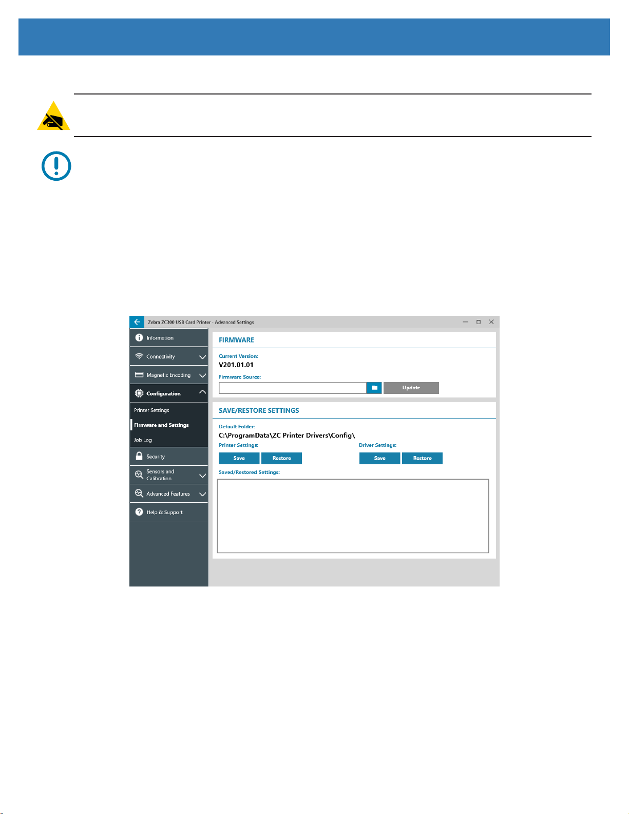
Before you replace the main logic board, save the printer conguration settings:
Step 4. Open the Printing preferences control panel and click on the Advanced utility.
Step 5. Click on the Printer Settings tab and select Firmware and Settings.
Step 6. In the Save/Restore Settings section, click on SAVE under Printer Settings.
Step 7. Enter a name for your saved data and click SAVE.
15
Page 22
Replacement Procedures
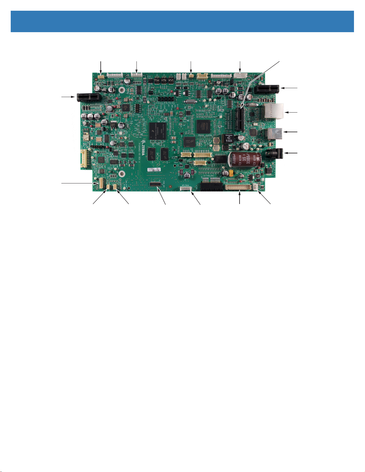
Feeder
Connection
(J28)
LCD (J26)
(not present on ZC100)
Ribbon
Authentication
Sensor (J24)
Card Detect
Sensor (J23)
Transport
Motor (J19)
Color Detect
Sensor (J22)
Printhead Cam
Sensor (J13)
Wireless Module
Connection (J18)
Motor (J16)
Ribbon Take-Up
Motor (J7)
Printhead (J6)Cam Lift
Encoder
Module
Connection (J8)
Printhead
Fan (J5)
Dual-Sided
Module
Connection (J4)
(not present on ZC100)
Ethernet (J3)
USB (J2)
Power (J1)
Removal
Step 1. Remove the left side cover (page 5).
Step 2. Remove the right side cover (page 7).
Step 3. Remove the rear cover (page 9).
Step 4. Disconnect the ribbons and cables from the main logic board. If equipped, disconnect the Wi-Fi
antenna from the Wi-Fi module.
Step 5. Remove the bottom cover (page 11).
16
Page 23
Replacement Procedures
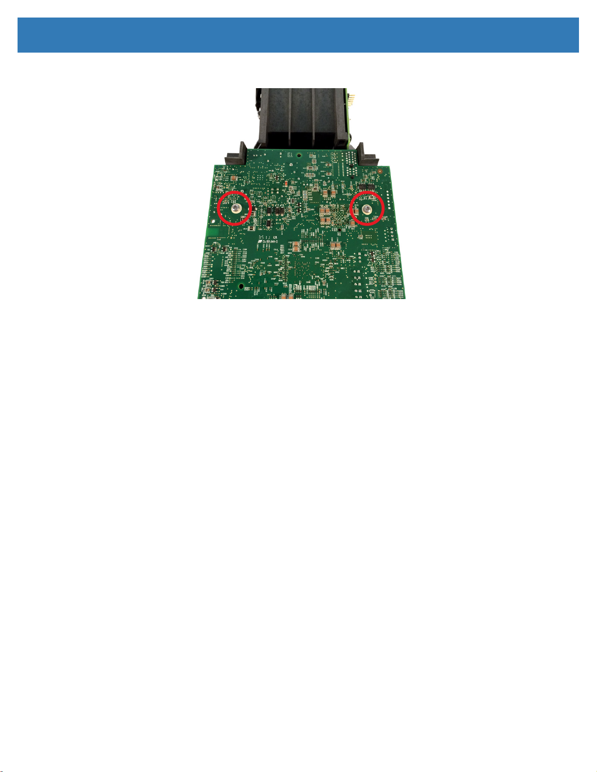
Step 6. Using a Torx T10 driver, remove the two screws securing the main logic board to the printer frame.
Step 7. Remove the main logic board lifting from the front and sliding forward.
Installation
Step 1. Place the rear of the main logic board into the printer frame with the connection receptacles placed
into their respective holes on the printer frame..
Step 2. Using a Torx T10 driver, secure the main logic board to the printer frame using the two screws.
Step 3. Replace the bottom cover.
Step 4. Reconnect the ribbons and cables to the main logic board.
Step 5. Replace the rear cover.
Step 6. Replace the side covers.
Step 7. Open the Printing preferences control panel and click on the Advanced utility.
Step 8. Click on the Printer Settings tab and select Firmware and Settings.
17
Page 24
Replacement Procedures
Restore Settings
Step 1. Open the Printing preferences control panel and click on the Advanced utility.
Step 2. Click on the Printer Settings tab and select Firmware and Settings.
Step 3. In the Save/Restore Settings section, click on Restore under Printer Settings.
Step 4. Select the le you save previously and click OPEN.
18
Page 25
Replacement Procedures
Printhead
Electrostatic Discharge • This replacement procedure must be performed at a static-free work station
or other suitable environment; an anti-static wrist strap must be worn and properly terminated, or other
appropriate protection must be used.
Hot Surface • Do not touch the printhead if the printer has been in service in the last ten minutes. It could
be very hot and cause a burn.
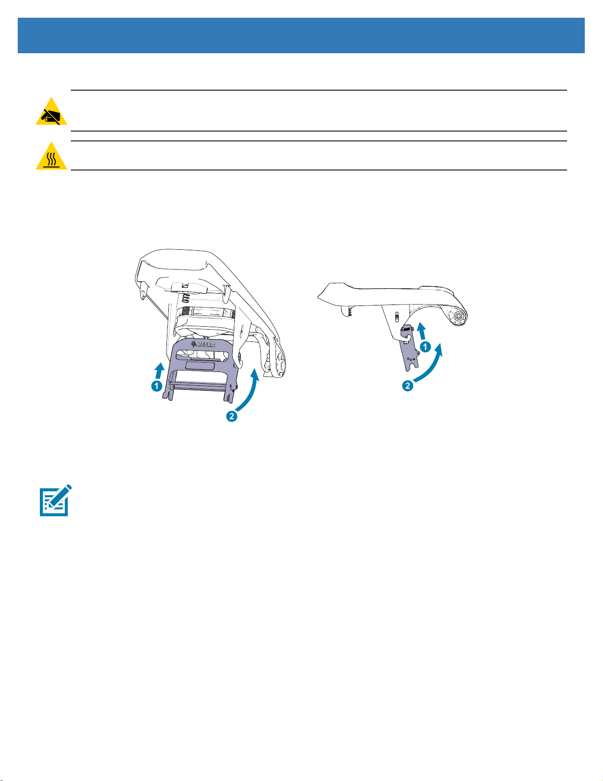
Removal
Step 1. Open the top cover.
Step 2. Push the printhead assembly upward until it becomes free from its locking hooks.
Step 3. Disconnect the printhead cable.
Installation
Note • Prior to installing the new printhead, note the serial number and resistance value.
Step 1. Connect the printhead cable to the printhead.
Step 2. Place the mounting knob into its receptacle and press upward to secure the printhead into its locking
hooks.
Step 3. Close the top cover.
19
Page 26
Replacement Procedures
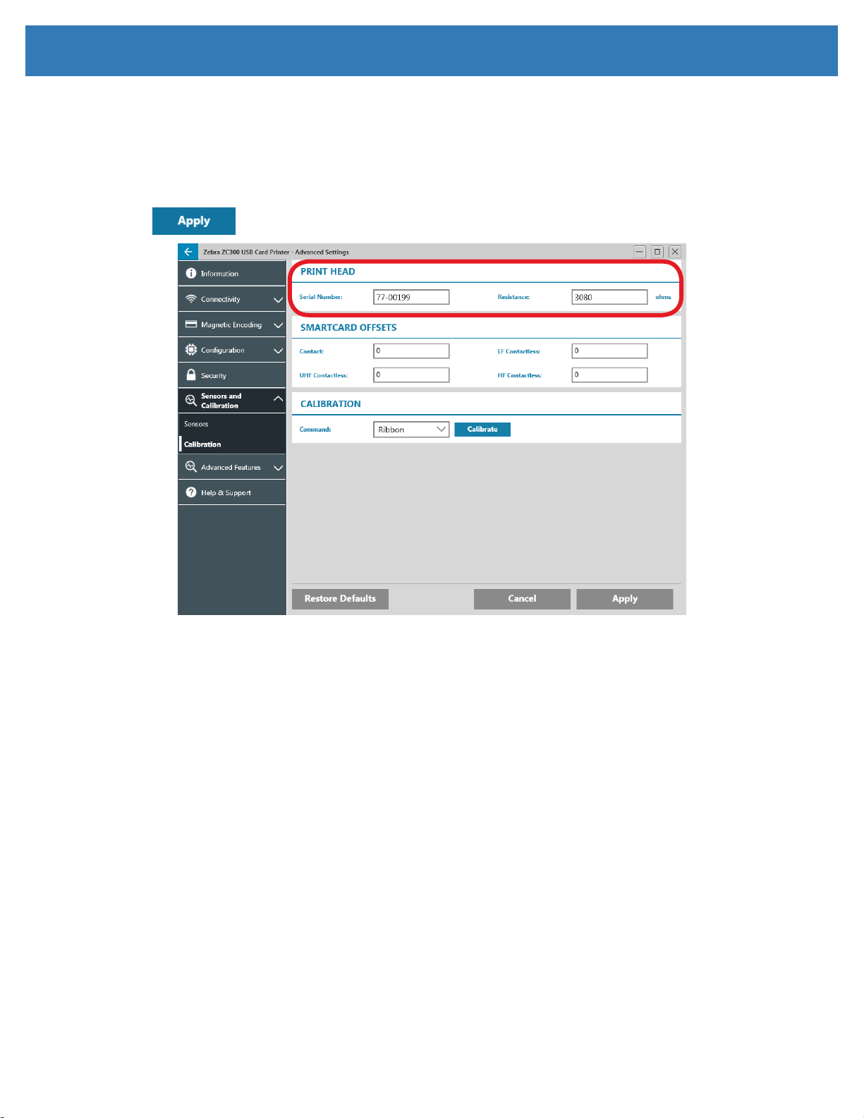
Restore Settings
Step 4. Open the Printing preferences control panel and click on the Advanced utility.
Step 5. Click on the Sensors and Calibration tab and select Calibration.
Step 6. In the Printhead section, enter the Serial Number and Resistance of the new printhead and click
.
20
Page 27
Replacement Procedures
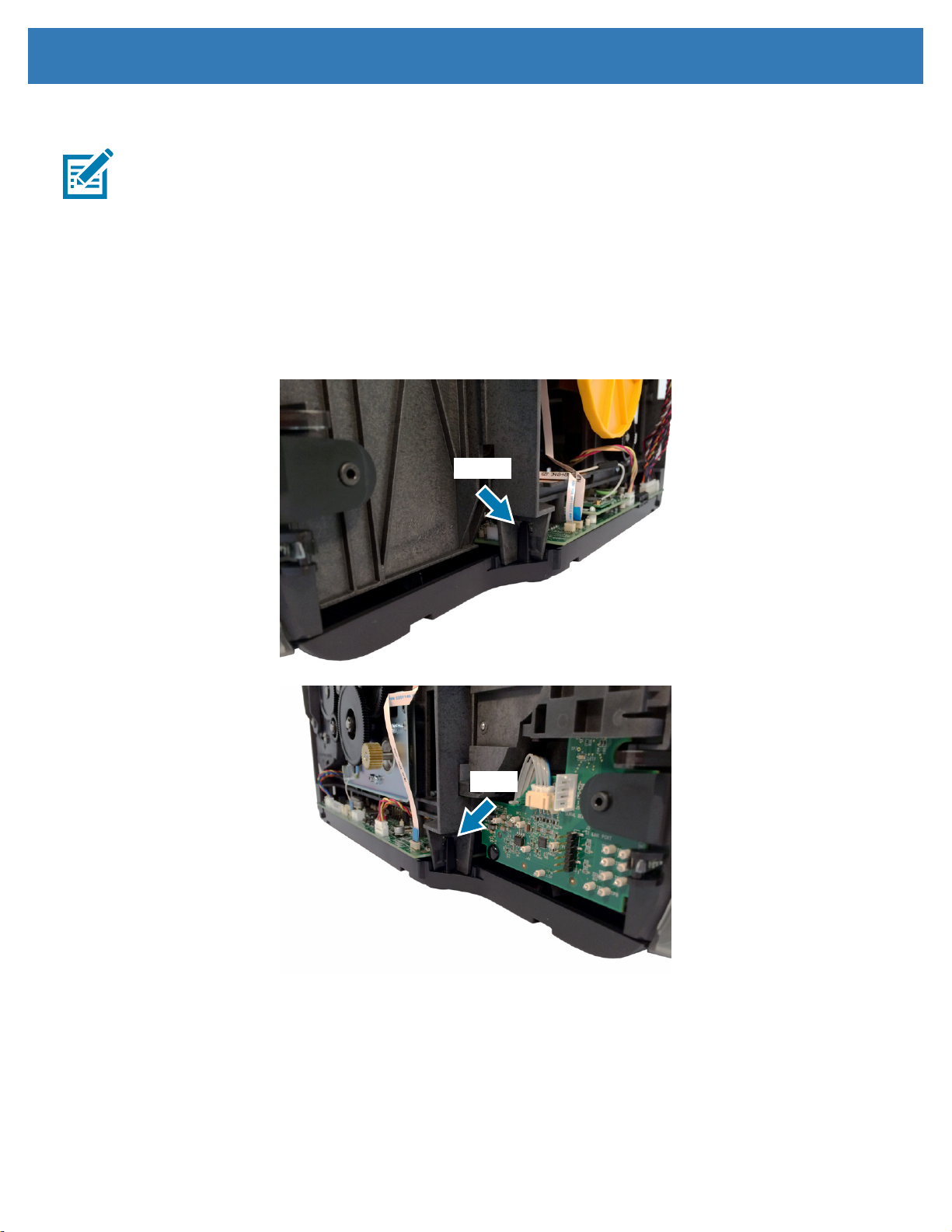
Printhead Cable
Note • Subsequent releases have added a sleeve for the printhead cable and printhead fan cable not
shown in the following pictures.
Removal
Step 1. Continue with Printhead Removal (see “Printhead” on page 19).
Step 2. Remove the right side cover (page 7).
Step 3. Disconnect the printhead cable (J6) from the main logic board.
Step 4. Release the printhead mounting frame from the top cover frame by carefully spreading the two
locking hooks outward.
21
Page 28

Replacement Procedures
Step 5. Remove the printhead cable from its routing through the top cover frame.
Step 6. Remove the printhead cable from its routing through the printer frame.
22
Page 29

Replacement Procedures
Installation
Step 1. Wrap the cable sleeve around the printhead cable and printhead fan cable.
Step 2. Route the cables through the printer frame.
Step 3. Route the printhead cable through the top cover frame. Make sure to leave enough cable to
comfortably attach the printhead.
Step 4. Connect the printhead cable to the main logic board (J6).
23
Page 30

Replacement Procedures
Step 5. Secure the printhead cable into the printhead mounting frame.
Step 6. Continue with Printhead Installation.
24
Page 31

Replacement Procedures
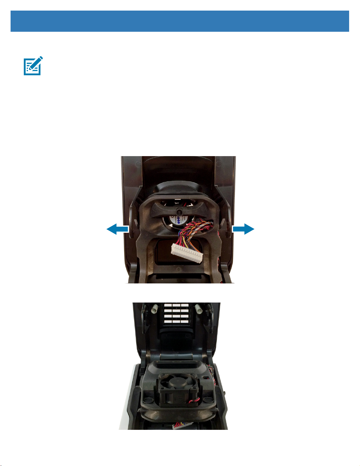
Printhead Fan
Removal
Step 1. Open the top cover.
Step 2. Remove the right side cover.
Step 3. Disconnect the printhead fan cable from the main logic board (J5).
Step 4. Continue with Printhead Removal (page 19).
Step 5. Disconnect printhead cable.
Step 6. Spread the printhead locking hooks apart to release the printhead mounting frame from the top cover
frame.
Step 7. While pushing from underneath, release the two locking tabs securing the printhead fan to the top
cover frame.
Step 8. Remove the printhead fan.
Installation
Step 1. Route printhead fan cable through the cable sleeve.
Step 2. Place the printhead fan into position and press into place until the tabs lock into position.
Step 3. Snap the printhead mounting frame back into position.
Step 4. Continue with Printhead Installation.
Step 5. Route the cables through the printer frame.
Step 6. Connect the printhead fan cable (J5) to the main logic board.
Step 7. Install the right side cover.
Step 8. Close the top cover.
25
Page 32

Replacement Procedures
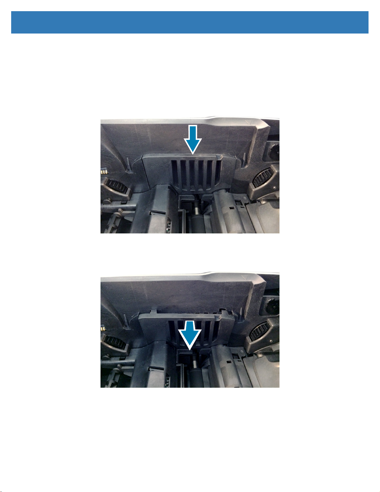
Dual-Sided Module
Removal
Step 1. Release the rear deck module locking handle by inserting the corner of a card between the locking
handle and the printer frame.
Step 2. Depress the two locking tabs securing the dual-sided module to the printer frame.
26
Page 33

Replacement Procedures
Step 3. Slide the dual-sided module upward and away from the printer.
27
Page 34

Replacement Procedures
Installation
Step 1. Place the dual-sided module into position with the locking tabs and the PCBA connection aligned
with the slots on the printer.
28
Page 35

Replacement Procedures
Step 2. Once aligned, place the dual-sided module ush against the printer and slide the dual-sided module
downward until it locks into position.
Testing
Step 1. Connect the printer power
Step 2. Open the Printing preferences Control Panel.
Step 3. In the Printing section of the Setup tab, set Print on Both Sides to On.
29
Page 36

Replacement Procedures
Step 4. From the Print Test Card drop-down list, click on Graphics Test Card.
The Graphics Test Card prints an image appropriate to the current ribbon
combination; and if Print on Both Sides is selected, a monochrome test image on
the back.
The Conguration Test Card prints printer conguration information using the K
(black) panel on the front only.
Step 5. The card will be sent to the printer.
Step 6. If the card fails to print, check the connection of the dual-sided module to the printer and print
another test card. If the failure continues, replace the dual-sided module.
30
Page 37

Replacement Procedures
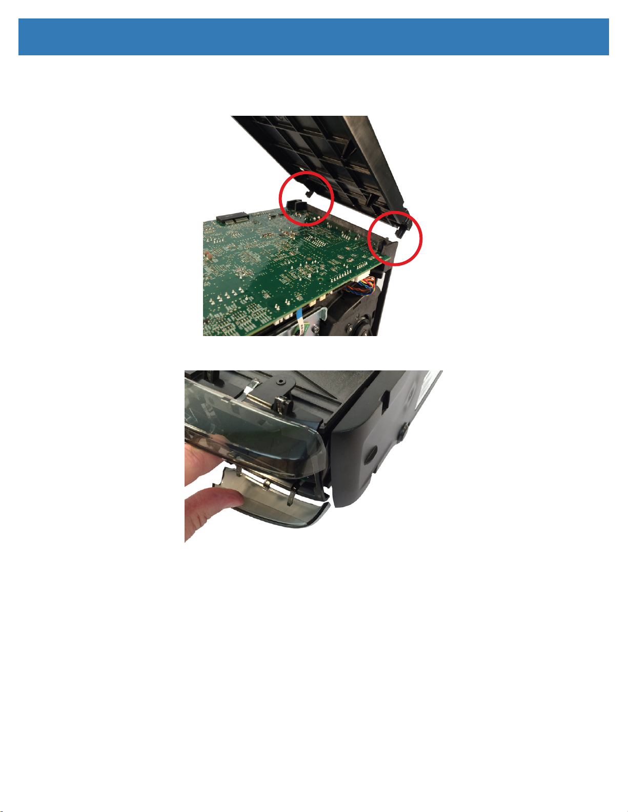
Dual-Sided Module Enclosure
Removal
Step 1. Continue with dual-sided module removal (page 26).
Step 2. Remove the transparent cover by squeezing the sides together at the top of the dual-sided module.
Step 3. Remove the reject chute.
31
Page 38

Replacement Procedures
Step 4. To remove the ipper enclosure, release the four locking tabs—in no particular order—and detach
the ipper enclosure from the ipper.
Installation
Step 1. Place the ipper mechanism into its enclosure and press inward to lock into place.
Step 2. Insert the bottom tab and rotate upward to snap the top tabs into place.
Step 3. Replace the reject chute.
Step 4. Continue with dual-sided module installation (page 26).
32
Page 39

Replacement Procedures
Wi-Fi Module
Electrostatic Discharge • This replacement procedure must be performed at a static-free work station
or other suitable environment; an anti-static wrist strap must be worn and properly terminated, or other
appropriate protection must be used.
Removal
Step 1. Open the top cover.
Step 2. Remove the right side cover (page 7).
Step 3. Unplug the antenna from the wireless PCBA.
Step 4. Remove the mounting posts from the main logic board.
Step 5. Remove the wireless antenna from the printer frame. Make sure to clean the area the antenna was
axed to with rubbing alcohol and a lint-free wipe.
33
Page 40

Replacement Procedures
Installation
Step 1. Place the wireless module into position with the connector on the module aligned with the connector
on the main logic board.
Step 2. Align the mounting posts with the holes in the main logic board.
MLB Connection
Mounting Post Connection
34
Page 41

Replacement Procedures
Step 3. Press the wireless module into position until it locks into place.
Wireless Antenna
Step 4. Remove the adhesive backing from the wireless module antenna and secure it to the printer frame in
the location shown (photo above).
Step 5. Replace the right side cover.
35
Page 42

Replacement Procedures
Feeder Assembly
Electrostatic Discharge • This replacement procedure must be performed at a static-free work station
or other suitable environment; an anti-static wrist strap must be worn and properly terminated, or other
appropriate protection must be used.
Removal
Step 1. Open the top cover.
Step 2. Remove the right side cover (page 7).
Step 3. Remove the left side cover (page 5).
Step 4. ZC150, ZC300, and ZC350: Unplug the LCD display ribbon connector from the main logic board (J25).
Step 5. Using two 30-mil cards, release the rst locking tab by sliding the card into the locking tab; leave the
card in position.
Step 6. Using the second 30-mil card, slide the card into the other locking tab.
Step 7. Lift the feeder assembly up and away from the printer frame.
36
Page 43

Replacement Procedures
Installation
Step 1. Place the feeder assembly into position on the printer frame and slide downward while holding open
the output hopper doors until the tabs lock into place.
Step 2. ZC150, ZC300, and ZC350: Route the LCD display ribbon through the printer frame and connect it
to the main logic board.
Step 3. Replace the right and left side cover.
37
Page 44

Replacement Procedures
Feeder Front Bezel
Note • This procedure is for reference only, there is no replacement kit for the feeder front bezel.
Removal
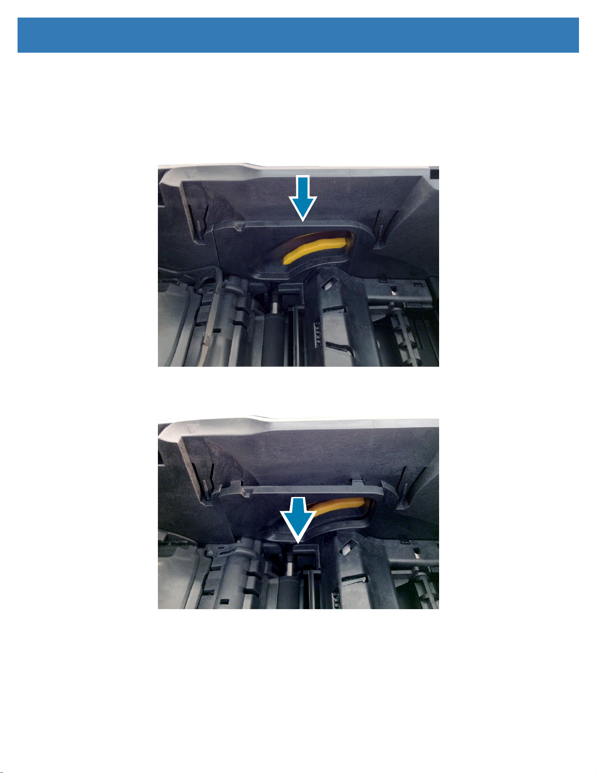
Step 1. Release the locking tabs on either side of the lower portion of the feeder front bezel.
Step 2. Open the input hopper door.
Step 3. Release the locking tab on he right side of the upper portion of the feeder front bezel.
Step 4. Remove the feeder front bezel. Note that the power button and spring are loose and may fall out.
38
Page 45

Replacement Procedures
Installation
Step 1. Insert the power button spring into the power button and place into the feeder front bezel.
Step 2. Secure the lower tabs of the feeder front bezel onto the feeder frame and rotate upward to secure
the upper locking tabs.
39
Page 46

Output Hopper Doors
Replacement Procedures
HINGE CLAW
DOOR
TENSIONER
HINGE CLAW
Removal
Step 1. Remove the left side cover (page 5).
Step 2. Remove the right side cover (page 7).
Step 3. Using a nylon pry tool, gently release the door hinge “claw” from the hinge post, repeat for the other
hinge.
Step 4. Carefully remove the door from the feeder front bezel.
40
Page 47

Replacement Procedures
Installation
Step 1. Insert one hinge and the door tensioner into position; The hinges insert at the inside of the output
hopper opening, and the tensioner inserts at the outside of the output hopper opening.
Step 2. Twist the door until the second hinge inserts at the inside of the output hopper opening.
Step 3. Attach the hinge claws to their respective hinge post.
Step 4. Replace the left and right side covers.
41
Page 48

Replacement Procedures
Power Button
Removal
Step 1. Continue with Feeder Front Bezel removal (page 38).
Step 2. Remove the power button and spring.
Installation
Step 1. Insert the power button spring onto its post in the power button and place the power button assembly
into the feeder front bezel.
Step 2. Continue with Feeder Front Bezel installation.
42
Page 49

Replacement Procedures
LED PCBA
Electrostatic Discharge • This replacement procedure must be performed at a static-free work station
or other suitable environment; an anti-static wrist strap must be worn and properly terminated, or other
appropriate protection must be used.
Removal
Step 1. Continue with Feeder Front Bezel removal (page 38).
Step 2. Disconnect the LED PCBA from the feeder PCBA at the power button side of the PCBA.
Installation
Step 1. Connect the LCD PCBA to the feeder PCBA.
Step 2. Continue with Feeder Front Bezel Installation.
43
Page 50

Rear Deck
Replacement Procedures
LOCKING HANDLE
NIP ROLLER
FINGER
NIP ROLLER
FINGER
Removal
Step 1. Open the top cover.
Step 2. Remove the left side ller panel (page 13).
Step 3. Remove the right side ller panel (page 14).
Step 4. Release the rear deck module locking handle by inserting the corner of a card between the locking
handle and the printer frame.
44
Page 51

Replacement Procedures
Step 5. With the locking handle released, and the side covers removed, depress the rear deck module
locking tabs from either side of the outside of the printer.
Step 6. Remove the module out from the printer frame.
Installation
Step 1. Place the rear deck assembly into position with the nip roller ngers pointing downward.
Step 2. With the nip roller ngers aligned to contact the lift cam, slide the rear deck into position and
continue inserting downward.
Step 3. Continue pressing downward until the module locks into place on both sides.
Step 4. Secure the module handle by rotating it toward the rear of the printer and pressing it into the printer
frame until it locks.
Step 5. Replace the left and right side ller panels.
Step 6. Replace the left and right side covers.
45
Page 52

Rear Deck Encoder Module
Electrostatic Discharge • This replacement procedure must be performed at a static-free work station
or other suitable environment; an anti-static wrist strap must be worn and properly terminated, or other
appropriate protection must be used.
NIP ROLLER
Replacement Procedures
LOCKING HANDLE
FINGER
PCBA CONNECTOR
Removal
Step 1. Open the top cover.
Step 2. Remove the left side ller panel (page 13).
Step 3. Remove the right side ller panel (page 14).
Step 4. Release the encoder module locking handle by inserting the corner of a card between the locking
handle and the printer frame.
46
Page 53

Replacement Procedures
Step 5. With the locking handle released, and the side covers removed, depress the rear deck module
locking tabs from either side of the outside of the printer.
Step 6. Remove the encoder module out from the printer frame.
Installation
Step 1. Grasp the encoder module so that the downstream nip bracket is in the open position.
47
Page 54

Replacement Procedures
Step 2. With the nip roller ngers aligned to contact the lift cam, slide the option module into position and
continue inserting downward.
Step 3. With the right side cover removed, guide the encoder module connector into its slot on the main logic
board.
Step 4. Continue pressing downward until the module locks into place on both sides.
Step 5. Secure the module handle by rotating it toward the rear of the printer and pressing it into the printer
frame until it locks.
Step 6. Replace the left and right side ller panels.
Step 7. Replace the left and right side covers.
48
Page 55

Replacement Procedures
Ribbon Color Detect Sensor Assembly
Electrostatic Discharge • This replacement procedure must be performed at a static-free work station
or other suitable environment; an anti-static wrist strap must be worn and properly terminated, or other
appropriate protection must be used.
Removal
Step 1. Open the top cover.
Step 1. Remove the right side cover (page 7).
Step 2. Remove the left side ller panel (page 13).
Step 3. Remove the right side ller panel (page 14).
Step 4. Disconnect the ribbon color detect sensor from the main logic board (J22).
49
Page 56

Replacement Procedures
Step 5. Use a nylon pry tool to release the two locking tabs securing the ribbon color detect sensor assembly
to the printer frame; release the rst and apply slight pulling force, then release the second.
Step 6. Carefully remove the sensor housing assembly being careful of the three springs underneath.
Installation
Step 1. Insert the three springs into the holes on the sensor housing.
50
Page 57

Replacement Procedures
Step 2. Route the sensor cable through the access hole.
Step 3. Align the three springs on the sensor housing with the three posts on the nip roller assembly.
Step 4. Press downward until the sensor housing locks into place.
Step 5. Connect the sensor cable to the main logic board at J22.
Step 6. Replace the left and right side ller panels.
Step 7. Replace the right side panel.
51
Page 58

Replacement Procedures
Card Detect Sensor Assembly
Electrostatic Discharge • This replacement procedure must be performed at a static-free work station
or other suitable environment; an anti-static wrist strap must be worn and properly terminated, or other
appropriate protection must be used.
Removal
Step 1. Continue with Ribbon Detect Sensor Assembly removal.
Step 2. Disconnect the card detect sensor from the main logic board (J23).
Step 3. Push the sensor assembly inward to unlock it from the printer frame.
Step 4. Remove the sensor assembly.
52
Page 59

Replacement Procedures
Installation
Step 1. Route the sensor cable through the access hole.
Step 2. Insert the sensor assembly at an angle with the long end into the printer frame and then rotating
downward.
Step 3. Press downward until the sensor assembly locks into place.
Step 4. Connect the sensor cable to the main logic board at J23.
Step 5. Continue with Card Detect Sensor Assembly installation.
53
Page 60

Front Deck Assembly
Removal
Replacement Procedures
NIP ROLLER
FRAME
IDLER ROLLER
CARD GUIDE
Step 1. Continue with Ribbon Color Detect Sensor Assembly removal (page 49).
Step 2. Use a nylon pry tool to release the two locking tabs securing the front deck assembly to the printer
frame.
Step 3. Remove the front deck assembly.
Installation
Step 1. Place the Front deck assembly into position.
Step 2. Press downward until the assembly locks into position.
54
Page 61

Replacement Procedures
Top Cover Assembly
Electrostatic Discharge • This replacement procedure must be performed at a static-free work station
or other suitable environment; an anti-static wrist strap must be worn and properly terminated, or other
appropriate protection must be used.
Removal
Step 3. Remove the left and right side panels.
Step 4. Disconnect the printhead cable (J6) and printhead fan cable (J5) from the main logic board.
Step 5. Carefully pry the top cover retaining nger on each side to release the top cover hinge.
Step 6. Remove the top cover assembly.
Step 7. Remove the printhead and printhead fan.
Installation
Step 1. Install the printhead (page 19) and printhead fan (page 25).
Step 1. Route the printhead cable and printhead fan cable through the top cover assembly.
Step 2. Route the printhead cable and printhead fan cable through the access hole on the printer frame.
Step 3. Insert the top cover assembly hinge on one side, and slightly pry the top cover retaining nger on the
other side to insert the other side.
Step 4. Connect the printhead cable (J6) and printhead fan cable (J5) to the main logic board.
Step 5. Replace the left and right side panels.
55
Page 62

Replacement Procedures
Top Cover Dampener
Removal
Step 1. Continue with Top Cover Assembly removal (page 55).
Step 2. Use a nylon pry tool to release either tab securing the top cover dampener to the printer frame.
Step 3. Push the dampener to the inside of the printer frame.
Installation
Step 1. Place the top cover dampener into position from the inside of the printer frame.
Step 2. Press the dampener into the printer frame until it locks into position.
Step 3. Continue with Top Cover Assembly installation.
56
Page 63

Replacement Procedures
Manual Advance Wheel
Removal
Step 1. Remove the right side cover.
Step 2. Disconnect the drive belt from the card entry/exit module wheel.
Step 3. Use a nylon pry tool to release the locking tab securing the manual advance wheel to the drive
platen spindle.
LOCKING TAB
Step 4. Pull the manual advance wheel o of the drive platen spindle.
57
Page 64

Replacement Procedures
Installation
Step 1. Place the drive belt onto the inner ring of the manual advance wheel.
Step 2. Place the manual advance wheel onto the drive platen spindle noting the alignment of the at edge
of the spindle and the corresponding notch in the manual advance wheel.
Step 3. Push the manual advance wheel onto the drive platen spindle until it locks into position.
Step 4. Pull the drive belt over the card entry/exit module wheel making sure it is properly seated.
ENTRY/EXIT
MODULE
WHEEL
Step 5. Replace the right side cover.
58
Page 65

Replacement Procedures
Ribbon Drive Assembly
Removal
Step 1. Remove the left side panel.
Step 2. Disconnect the ribbon drive assembly cable from the main logic board (J7).
Step 3. Use a nylon pry tool to depress the locking tabs securing the ribbon drive assembly to the printer
frame. The locking tabs are part of the motor enclosure.
Step 4. Remove the ribbon drive assembly.
59
Page 66

Replacement Procedures
Installation
Step 1. Place the ribbon drive assembly into position. Note the ribbon drive assembly cable is outside the
printer frame and aligned with the routing notch.
Step 2. Press the ribbon drive assembly inward until it locks into position.
Step 3. Connect the ribbon drive assembly cable to the main logic board at J7.
Step 4. Replace the left side panel.
60
Page 67

Replacement Procedures
Card Entry/Exit Module
Removal
Step 1. Remove the right side panel.
Step 2. Remove the drive belt from the card entry/ext module wheel.
Step 3. Depress the tab securing the card entry/exit module to the printer frame.
61
Page 68

Replacement Procedures
Step 4. Pull the card entry/exit module out of the printer frame.
Installation
Step 1. Insert the card entry/exit module into position.
Step 2. Push the card entry/exit module into the printer until it locks into position.
Step 3. Pull the drive belt over the card entry/exit module wheel making sure it is properly seated.
Step 4. Replace the right side panel.
62
Page 69

Replacement Procedures
Tri-Sensor PCBA
Electrostatic Discharge • This replacement procedure must be performed at a static-free work station
or other suitable environment; an anti-static wrist strap must be worn and properly terminated, or other
appropriate protection must be used.
Removal
Step 1. Remove the left side cover.
Step 2. Disconnect the tri-sensor PCBA cable from the main logic board (J24).
Step 3. Use a nylon pry too to remove the pin securing the ribbon encoding wheel to the printer frame.
Step 4. Remove the wheel.
Step 5. Use a nylon pry tool to remove the pin securing the tri-sensor PCBA to the printer frame.
63
Page 70

Replacement Procedures
Step 6. Use a nylon pry tool to pop out the locking spreader.
Step 7. Remove the tri-sensor PCBA.
Installation
Step 1. Slide the tri-sensor PCBA into position with the protrusion going into the receptacle on the printer
frame.
Step 2. Snap the locking spreader into the printer frame.
Step 3. Insert the locking pin.
Step 4. Place the ribbon encoder wheel onto the printer frame, make sure it is in the correct orientation and
sits in the gap sensor.
Step 5. Insert the locking pin and press inward.
Step 6. Connect the tri-sensor PCBA cable to the main logic board (J24).
Step 7. Replace the left side panel.
64
Page 71

Replacement Procedures
Cam Position Sensor PCBA
is replacement procedure must be performed at a static-free work station or other suitable environment; an anti-static wrist strap must be worn and properly terminated, or other appropriate protection
must be used.
Removal
Step 1. Remove the left side panel.
Step 2. Disconnect the cam sensor cable to the main logic board (J13).
Step 3. Use a removal tool to remove the E-clip securing the transitional gear.
Step 4. Remove the gear.
Step 5. Use a nylon pry tool to remove the locking pin securing the cam position sensor PCBA.
Step 6. Use a nylon pry tool to remove the cam position sensor PCBA.
65
Page 72

Replacement Procedures
Installation
Step 1. Place the cam position sensor PCBA into position.
Step 2. Snap the locking spreader onto the printer sub-frame.
Step 3. Insert the locking pin.
Step 4. Place the transitional gear onto its spindle. Make sure the gears mesh properly.
Step 5. Use the E-clip to secure the gear to its spindle.
Step 6. Connect the cam position sensor PCBA cable to the main logic board at J13.
Step 7. Replace the left side cover.
66
Page 73

Replacement Procedures
Lift Cam Motor
Removal
Step 1. Continue with Main Logic Board removal (page 15).
Step 2. Use a Torx T10 driver to remove the two screws securing the lift cam motor to the printer frame.
Step 3. Remove the motor.
Installation
Step 1. Place the motor into position.
Step 2. Use a Torx T10 driver to secure the lift cam motor to the printer frame using two screws.
Step 3. Continue with Main Logic Board Installation.
67
Page 74

Replacement Procedures
Platen Drive Motor
Removal
Step 1. Disconnect the platen drive motor from the main logic board (J16).
Step 2. Disconnect the cam sensor cable from the main logic board (J13).
Step 3. Use a Torx T10 driver to remove the three screws securing the sub-frame to the printer frame.
Step 4. Remove the sub-frame and attached components.
Step 5. Use a Torx T10 driver to remove the two screws securing the motor to the sub-frame.
Installation
Step 1. Use a Torx T10 driver to secure the platen drive motor to the printer sub-frame using two screws.
Step 2. Use a Torx T10 driver to secure sub-frame and its attached components to the printer frame using
the three screws.
68
Page 75

Transport Rollers
Replacement Procedures
REAR
ROLLER
REAR
ROLLER
FRONT
ROLLER
MIDDLE
ROLLER
MIDDLE
ROLLER
FRONT
ROLLER
69
Page 76

Replacement Procedures
Removal - Rear
Step 1. Continue with Rear Deck removal (page 44).
Step 2. Lift the rear transport roller up and out through the access hole.
Removal - Front
Step 3. Continue with Front Deck Assembly removal (page 54).
Step 4. Continue with Manual Advance Wheel removal (page 57).
Step 5. Remove the front transport roller by lifting it up and out of the access hole.
70
Page 77

Replacement Procedures
Step 6. Remove the middle transport roller by lifting it up, sliding it toward the front of the printer and out of
the access hole.
Installation - Front
Step 1. Insert the middle platen roller through the access hole, sliding it toward the rear of the printer,
and into its slot. Make sure the bearing is seated in its slot with the rounded side of the bearing
downward.
Step 2. Insert the front platen through the access hole and into its slot.
Installation - Rear
Step 3. Insert the platen through the access hole and into its slot.
Step 4. Continue with Front Deck installation; continue with Rear Deck installation; continue with Manual
Advance Wheel installation.
71
Page 78

Replacement Procedures
Static Brush
There are four (4) static brushes axed to dierent locations on the printer:
y Card exit—located behind the card feed roller at
the rear of the feeder assembly.
y Card entry—located at the front of the printer
frame. Remove the feeder assembly for access
see “Feeder Assembly” on page 36.
y Front Deck Assembly—located on the front face
of the nip roller frame. Remove the front deck
assembly for access see “Front Deck Assembly”
on page 54.
y Card rear exit -- located on the rear face of the
printer frame. Remove the rear cover (page
74), or the dual-sided module if equipped see
“Dual-Sided Module” on page 26.
72
Page 79

Replacement Procedures
Removal
Step 1. Remove the component the static brush is attached to as necessary.
Step 2. Remove the static brush by peeling it from the component.
Installation
Step 1. Clean the surface with isopropyl alcohol and a lint free cloth.
Step 2. Ax the static brush to the surface and press rmly to seat the adhesive.
Step 3. Replace the component as necessary.
73
Page 80

Replacement Procedures
Feet
Note: While it is not necessary to remove the bottom cover for this procedure, it is recommended to avoid
damaging any other parts of the printer.
Removal
Step 1. Remove the bottom cover (page 74).
Step 2. Using a nylon pry tool, remove the foot (feet) from the printer bottom cover.
FOOT
FOOT
FOOT
FOOT
Installation
Step 1. Clean the surface with isopropyl alcohol and a lint free cloth.
Step 2. Ax the foot (feet) to the recess in the bottom panel and press rmly to seat the adhesive.
74
Page 81

Troubleshooting
Introduction
The objective of troubleshooting is to relate a problem to an associated assembly or system function, in order to
most eciently isolate and repair the problem. Typically, this involves determining the failure symptom and then
checking one or more possible causes of the failure.
In general, for a given failure symptom on or more possible causes are listed, with suggested corrective action to
take. These causes should be checked and corrective actions taken in the order given; as they are listed in order of
likelihood and complexity.
This chapter lists the error codes and the solutions to the problems related to those error codes. Where applicable,
you will be directed to the proper replacement procedure to correct the error.
For additional information on troubleshooting and advanced operations, refer to the Zebra knowledge Base at
km.zebra.com.
Troubleshooting Table
CODE MESSAGE PROBABLE CAUSE POSSIBLE SOLUTION
• A version of rmware was sent to the printer
5 Invalid rmware
7 Firmware upgrade failed
8 Critical error • Hardware failure. • Contact technical support.
11 Invalid hardware
4001 Out of cards
5001 Out of ribbon
5002 Incompatible ribbon
that was not compatible with the printer
model.
• Corrupt rmware le.
• Power interruption.
• Hardware has been installed on the printer
that is not compatible with the printer model.
• No cards are present in the input hopper.
• Input hopper card detect sensor has
malfunctioned.
• No ribbon is present in the printer.
• Ribbon has reached the end of the roll.
• There are no panel sets remaining on the
ribbon authentication chip.
• Ribbon has been loaded in the printer that is
not compatible with the printer model.
• Check the rmware le and verify
compatibility with the printer model and try
again.
• Check the rmware le and verify
compatibility with the printer model and try
again.
• Remove invalid hardware.
• Load cards into the input hopper.
• If the error persists after loading cards,
contact technical support.
• Load/replace ribbon.
• If the error persists after loading cards,
contact technical support.
• Replace ribbon with ribbon that is compatible
with the printer model.
75
Page 82

Troubleshooting
CODE MESSAGE PROBABLE CAUSE POSSIBLE SOLUTION
5003 Ribbon jam
5007
5008
7001 Card feeding failed
7003 Check printhead cable
7008 Print cover open
7010
7013
7023 Encoding cam blocked
Ribbon color detection
failed
Ribbon authentication
failed
Printhead motion
blocked
Motor voltage out of
range
• Ribbon is broken.
• Ribbon payout encoder is out of position.
• Ribbon payout encoder sensor has
malfunctioned.
• Printing o the front edge of the card (see
page #).
• Ribbon color detect sensor requires
calibration.
• Ribbon authentication chip is incorrect for
the ribbon.
• Ribbon sensor reector on the printhead is
dirty.
• Ribbon color detect sensor has
malfunctioned.
• Ribbon authentication chip is dirty, damaged,
or not programmed properly.
• Ribbon authentication chip contacts on the
printer are damaged.
• The ribbon is not a genuine Zebra ribbon.
• Cards are stuck together in the input hopper.
• Back surface of the card is too slick for the
card pick roller.
• Card pick roller is dirty.
• Entry/exit module is dirty.
• The card used is outside of the printer
specication.
• Printhead cable is unplugged, not fully
seated, or damaged.
• The print cover is open.
• The print cover open sensor has
malfunctioned.
• There is an obstruction in the printer.
• An object has been placed on top of the
printer.
• The printhead cam motor has malfunctioned.
• One of the motors in the printer has
malfunctioned.
• There is an obstruction in the encoding
module.
• The wires in the module are blocking
movement of the cam.
• Repair the ribbon (see page 81).
• If the error persists after repairing the ribbon,
contact technical support.
• Adjust the X-Oset (refer to Driver User
Guide).
• Calibrate the ribbon color detect sensor
(refer to Driver User Guide).
• Replace the ribbon.
• Clean the ribbon sensor reector on the
printhead.
• If the error persists, contact technical
support.
• Clean the authentication chip.
• Replace the ribbon.
• If the error persists, contact technical
support.
• Check the cards and reload into the input
hopper.
• Clean the printer (refer to User Guide).
• If the error persists, contact technical
support.
• Check the connection of the printhead cable
and the printhead.
• If the error persists, contact technical
support.
• Close the print cover.
• If the error persists, contact technical
support.
• Remove the obstruction.
• Remove the object from on top of the printer.
• If the error persists, contact technical
support.
• Contact technical support.
• Remove the obstruction.
• Replace the encoding module.
• If the error persists, contact technical
support.
76
Page 83

Troubleshooting
CODE MESSAGE PROBABLE CAUSE POSSIBLE SOLUTION
• Open and close the print cover.
• Open the print cover, use the manual
advance wheel to move the stuck card out of
7026 Card jam in ipper
7028 Input hopper open
7029 Flipper rotation failed • A card is blocking the rotation of the ipper.
7032 Manual feed failed
7033 Flipper PCBA failed
7034 Reject bin full
7035 Card jam in encoder
7036 Card jam in printer
• A card is stuck in the ipper, or between the
ipper and the printer.
• The input hopper cover is open.
• The input hopper cover open sensor has
malfunctioned.
• A card was inserted in the manual feed slot
when it was not expected to be inserted.
• A communication error occurred between the
main PCBA and the ipper PCBA.
• The maximum number of cards that can be
held in the reject bin has been reached.
• There is an obstruction in the options
module.
• The options module is not installed properly.
• The options module has malfunctioned.
• There is an obstruction in the card path.
• The ribbon is stuck to the card.
• The card is slipping on the drive rollers.
• The card used is outside of the printer
specication.
the ipper, then close the print cover.
• Remove the ipper window and remove the
stuck card.
• Remove the ipper and remove the stuck
card.
• Replace the ipper module.
• Close the input hopper cover.
• If the error persists, contact technical
support.
• Check the reject bin for any cards that may
have fallen back into the ipper.
• Remove the ipper window and remove the
stuck card.
• Remove the ipper and remove the stuck
card.
• Replace the ipper module.
• Open the input hopper, remove the stuck
card, close the input hopper.
• If the error persists, contact technical
support.
• Power cycle the printer.
• Replace the ipper module.
• If the error persists, contact technical
support.
• Open the print cover, remove the cards from
the reject bin, close the print cover.
• Remove the options module, manually insert
a card in the module and check for any
obstructions.
• Ensure the options module is properly
seated in the printer with the locking tabs on
both sides properly engaged.
• Replace the options module.
• If the error persists, contact technical
support.
• Open and close the print cover.
• Open the print cover, use the manual
advance wheel to move the stuck card, then
close the print cover.
• Open the print cover, remove the stuck
ribbon from the card, close the print cover.
• Clean the printer (refer to User Guide).
• Verify cards meet printer specication.
• If the error persists, contact technical
support.
77
Page 84

Troubleshooting
CODE MESSAGE PROBABLE CAUSE POSSIBLE SOLUTION
• Cards are stuck together in the input hopper.
• Back surface of the card is too slick for the
card pick roller.
7038 Card entrance jam
7039 Card exit jam
7045 Pusher plate jam
7048 Clean printer
9001 Magnetic read failed
9002
9004 No magnetic stripe
21009 Critical error • Hardware failure. • Contact technical support.
21011 Critical error • Hardware failure. • Contact technical support.
21017 Options PCBA failed
Magnetic encoding
failed
• Card pick roller is dirty.
• Entry/exit module is dirty.
• The card used is outside of the printer
specication.
• There is an obstruction in the card path or in
the output hopper.
• The card is slipping on the drive rollers.
• There is an obstruction in the input hopper
preventing the pusher plate from reaching
the UP position.
• The pusher plate lift mechanism has
malfunctioned.
• The printer has reached the cleaning
threshold and the printer is set to stop
printing when the threshold is reached.
• The card is damaged.
• The options module is not installed properly.
• The options module has malfunctioned.
• The incorrect magnetic coercivity has been
selected.
• The magnetic encoder is dirty.
• The card is damaged.
• The options module is not installed properly.
• The options module has malfunctioned.
• The incorrect magnetic coercivity has been
selected.
• The magnetic encoder is dirty.
• The card does not have a magnetic stripe.
• The card was inserted in the incorrect
orientation.
• A communication error occurred between the
main PCBA and the options PCBA.
• Check the cards and reload into the input
hopper.
• Clean the printer (refer to User Guide).
• Verify cards meet printer specication.
• If the error persists, contact technical
support.
• Clear the output hopper.
• Remove the card if visible. If not visible,
open and close the print cover.
• Clean the printer (refer to User Guide).
• If the error persists, contact technical
support.
• Remove the obstruction.
• Close the input hopper door.
• If the error persists, contact technical
support.
• Clean the printer (refer to User Guide).
• Check the card for damage.
• Check the coercivity setting.
• Clean the printer (refer to User Guide)
• Ensure the options module is properly
seated in the printer with the locking tabs on
both sides properly engaged.
• Replace the options module.
• If the error persists, contact technical
support.
• Check that the card has a magnetic stripe.
• Reinsert the card in the proper orientation.
• Power cycle the printer.
• Replace the options module.
• If the error persists, contact technical
support.
78
Page 85

Troubleshooting
Identifying Print Quality Issues
Print quality refers to the quality of the text, barcodes, and images that are printed on the lm.
Color Accuracy
When the colors on the printed card do not match the expected result, there are several steps that may be taken to
get the desired output.
1. If using the driver, make adjustments in the Color Panels tab of the Print Optimization and Adjustment
utility in the Printer Preferences control panel.
2. If using the driver, create and apply a Windows ICC color prole.
3. Whether using the driver or not, contact Zebra to create a custom lookup table that can be downloaded to
the printer using the Printer Preferences control panel.
Dirt and Debris
Spots and speckles appearing on the card may be caused by dirt and debris in the printer.
y Replace the cleaning rollers.
y Clean the printer (refer to the User Guide).
Image Placement
If the image printed on the card seems to have shifted, this may be an image placement issue.
y Use the Alignment adjustments in the Print Optimization and Adjustment utility in the Printer Preferences
control panel.
Smear
Smear may occur when a sudden shift from a dark color to a light color occurs and the printhead has not suciently
cooled when printing the light color, thereby the dark color appears to “smear” into the light color.
y Lower the Intensity value on the Color Panels tab of the Print Optimization and Adjustment utility in the
Printer Preferences control panel.
Black Extraction
When the black text or images does not appear black or crisp, or text that is supposed to be black appears muddy
or not sharp, this may be an issue where the black text or image was not printed using the black panel.
y Check the source image; RGB values up to 25,25,25 can be printed as black by using the sliders on the K
Extraction page. If RGB values are greater than 25,25,25, then the image will need to be modied to bring
the RGB values under this threshold.
y Adjust the properties in the Front or Back K Extraction menu (refer to the Driver User Guide).
Ribbon Wrinkle
Ribbon wrinkle appears as a streak of color that was not part of the original image. It typically originates from the
edges of the card, and sometimes occurs when printing a really dark image, or near the transition between really
dark and really light images
79
Page 86

Troubleshooting
If this occurs, contact Zebra Tech Support.
Mis-registration
Mis-registration occurs when the Y, M, C, and/or K panels are not properly aligned with each other. The eect may
appear as a lack of sharpness, or a color halo.
If this occurs, contact Zebra Tech Support.
Ethernet Indicators—Detail
Link/Activity Indicator (Green)
O No link (disconnected)
On Network link has been established
Blinking Network activity has been detected
Speed Indicator (Orange)
O No link (disconnected)
The LED blinks once (one blink, pause,
1 Blink
2 Blinks
If both LEDs are o, the printer has not detected the presence of a network cable. To solve the problem:
Step 1. Verify that the network cable is appropriate and has an RJ-45 connector.
Step 2. Remove the network cable from the printer. Plug the network cable back in until you hear a positive
click. Check the other end of the cable in the same manner. If the printer still does not detect a cable,
then continue.
one blink, etc.) when a 10Base link has
been established.
The LED blinks twice (two blinks,
pause, two blinks, etc.) when a
100Base link has been established.
Step 3. Connect the printer to a known good network. If the printer is still unable to detect the network cable,
contact Technical Support for assistance
80
Page 87

Troubleshooting
Ribbon Repair
If a ribbon breaks, you can repair it easily using transparent tape.
Step 1. Using a scissors, cut the broken ribbon from the payout spool in as straight a line as possible.
81
Page 88

Troubleshooting
Step 2. Using a piece of transparent (Scotch) tape, ax the cut end of the ribbon to the take-up spool. You
do not have to remove the existing ribbon on the take-up spool.
Step 3. Advance the take-up spool.
Step 4. Reinstall the ribbon.
Step 5. If the ribbon continues to break, there may be another issue with the printer or the printer settings,
contact Technical Support.
82
 Loading...