

Page 1

Color profile: Disabled
Composite Default screen
User's Guide
For the Zebra Z4000™ and Z6000™ Printers
H:...uspiran2.vp
Thu Jun 18 15:49:04 1998
Customer order # 77460L Manufacturer part # 77460LB Rev. 2
1
Page 2
Color profile: Disabled
Composite Default screen
Proprietary Statement
This manual contains proprietary information of Zebra Technologies Corporation. It is in-
tended solely for the information and use of parties operating and maintaining the equip-
ment described herein. Such proprietary information may not be used, reproduced, or
disclosed to any other parties for any other purpose without the expressed written permis-
sion of Zebra Technologies Corporation.
Product Improvements
Continuous improvement of products is a policy of Zebra Technologies Corporation. All
specifications and signs are subject to change without notice.
FCC Compliance Statement
NOTE:
This equipment has been tested and found to comply with the limits for a Class B
digital device, pursuant to Part 15 of the FCC Rules. These limits are designed to provide
reasonable protection against harmful interference in a residential installation. This
equipment generates, uses and can radiate radio frequency energy and, if not installed and
used in accordance with the instructions, may cause harmful interference to radio com-
munications. However, there is no guarantee that the interference will not occur in a par-
ticular installation. If this equipment does cause harmful interference to radio or
television reception, which can be determined by turning the equipment off and on, the
user is encouraged to try to correct the interference by one or more of the following
measures:
n
Reorient or relocate the receiving antenna.
n
Increase the separation between the equipment and the receiver.
n
Connect the equipment into an outlet on a circuit different from that to which the
receiver is connected.
n
Consult the dealer or an experienced Radio/TV technician for help.
NOTE:
This unit was tested with shielded cables on the peripheral devices. Shielded
cables must be used with the unit to insure compliance.
The user is cautioned that any changes or modifications not expressly approved by Zebra
Technologies Corporation could void the users authority to operate the equipment.
Canadian DOC Compliance Statement
This digital apparatus does not exceed the Class A limits for radio noise emissions from
digital apparatus as set out in the radio interference regulations of the Canadian Depart-
ment of Communications.
Liability Disclaimer
Zebra Technologies Corporation takes steps to assure that its published Engineering
Specifications and Manuals are correct; however, errors do occur. Zebra Technologies
Corpora tion reserves the right to correct any such errors and disclaims liability resulting
therefrom.
No Liability for Consequential Damage
In no event shall Zebra Technologies corporation or anyone else involved in the creation,
production, or delivery of the accompanying product (including hardware and software)
be liable for any damages whatsoever (including, without limitation, damages for loss of
business profits, business interruption, loss of business information, or other pecuniary
loss) arising out of the use of or the results of use of or inability to use such product, even
if Zebra Technologies Corporation has been advised of the possibility of such damages.
Because some states do not allow the exclusion or limitation of liability for consequential
or incidental damages, the above limitation may not apply to you.
Copyrights
This copyrighted manual and the label printers described herein are owned by Zebra Tech-
nologies Corporation. All rights are reserved. Unauthorized reproduction of this manual or
the software in the label printer may result in imprisonment of up to one year and fines of
up to $10,000 (17 U.S.C.506). Copyright violators may be subject to civil liability.
H:...uspiran2.vp
Thu Jun 18 15:49:05 1998
®
IBM
is a registered trademark of IBM Corporation.
Goo Gone
Zebra
Z
®
is a Registered Trademark of Magic American Corporation
®
, Stripe®, ZPL®, and ZPL II®are registered trademarks, andZSeries,
4000, and Z6000 are trademarks of Zebra Technologies Corporation.
© Zebra Technologies Corporation
2
Page 3
Color profile: Disabled
Composite Default screen
H:...uspiran2.vp
Thu Jun 18 15:49:10 1998
Z Series™ User’s Guide i
3
Page 4

Color profile: Disabled
Composite Default screen
ii Z Series™ User’s Guide
H:...uspiran2.vp
Thu Jun 18 15:49:10 1998
4
Page 5

Color profile: Disabled
Composite Default screen
Contents
Welcome
Getting Started 1
Communications 2
Printer Power 2
Printer Configuration
Z Series™ Configuration 3
Media & Ribbon Loading
Loading Media 5
Loading Ribbon 7
Removing Ribbon 8
Media Sensor Positioning
Media Sensor Operation 9
Media Sensor Position 9
Printer Operational Check 10
Printer Operation
Operator Interface 13
Front Panel Keys 13
Front Panel LEDs 14
Additional Front Panel Controls 14
H:...uspiran2.vp
Wed Jul 08 11:23:52 1998
Z Series™ User’s Guide iii
5
Page 6

Color profile: Disabled
Composite Default screen
Media Calibration
Auto-Calibration 17
Calibration Control 17
Care & Adjustments
Cleaning 19
Lubrication 24
Printhead Pressure Adjustment 24
Power Rewind/Power Peel
Media Alignment 25
Printer Options
LCD Display (Deluxe Front Panel) 27
Power Rewind/Power Peel Option 28
Value Peel Option 30
Cutter Option 31
Electronics Options 33
Communication Options 33
Troubleshooting
Power On Self-Test 35
Troubleshooting Tables 35
Printer Self-Tests 38
Resetting Factory Defaults 44
Initializing the Flash Memory and PCMCIA Card 45
Automatically Executed Format 45
Print Error Conditions 46
iv Z Series™ User’s Guide
6
H:...uspiran2.vp
Wed Jul 08 11:23:52 1998
Page 7
Color profile: Disabled
Composite Default screen
Printer Specifications
General Specifications 47
Printing Specifications 48
Ribbon Specifications 48
Media Specifications 49
Zebra Programming Language (ZPL II
®
)50
Bar Codes 50
Standard Printer Fonts 51
Optional Printer Fonts 53
Appendix A
Printer Configuration
(Standard Front Panel)
55
Printer Configuration
(Deluxe Front Panel)
Appendix B
Communication Interfaces 69
Serial Data Communications 69
Parallel Data Communications 72
Appendix C
AC Power Cord 73
Fuse Replacement 74
Shipping 74
Setting Darkness For “In-Spec” Bar Codes 74
ASCII Code Chart 77
Glossary
Index
59
H:...uspiran2.vp
Wed Jul 08 11:23:52 1998
Z Series™ User’s Guide v
7
Page 8
Color profile: Disabled
Composite Default screen
vi Z Series™ User’s Guide
8
H:...uspiran2.vp
Wed Jul 08 11:23:52 1998
Page 9
Color profile: Disabled
Composite Default screen
Welcome
Congratulations! You have just purchased a high-quality thermal demand printer manufactured by the industry leader in quality, service,
and value. For over 25 years, Zebra Technologies Corporation has
provided customers with the highest caliber of products and support.
This user’s guide provides all the information you will need to operate
the printer on a daily basis.
To create and print label formats, refer to the ZPL II Programming
Guide (part # 46469L). This guide is available by contacting your
distributor or Zebra Technologies Corporation.
In addition, label preparation software is available. Contact your distributor or Zebra Technologies Corporation for further information.
The Z Series™ Maintenance Manual (part # 77450L) contains the information you may need to properly maintain your printer.
Getting Started
Unpacking
Save the carton and all packing materials in case shipping is required.
Inspect the printer for possible shipping damage:
n
Check all exterior surfaces for damage.
n
Raise the Media Access Door and inspect the Media Compartment
for damage.
Reporting Damage
If you discover shipping damage:
n
Immediately notify the shipping company and file a damage report.
n
Retain the carton and all packing material for inspection.
n
Notify your local Zebra distributor of the damage.
Zebra Technologies Corporation is not responsible for any damage
incurred during shipment of the printer and will not cover the repair of
this damage under its warranty policy. Any damage claim should be
filed with the shipping company.
H:...uspiran2.vp
Mon Jun 22 10:28:44 1998
Z Series™ User’s Guide 1
9
Page 10
Color profile: Disabled
Composite Default screen
For shipping information, refer to Appendix C.
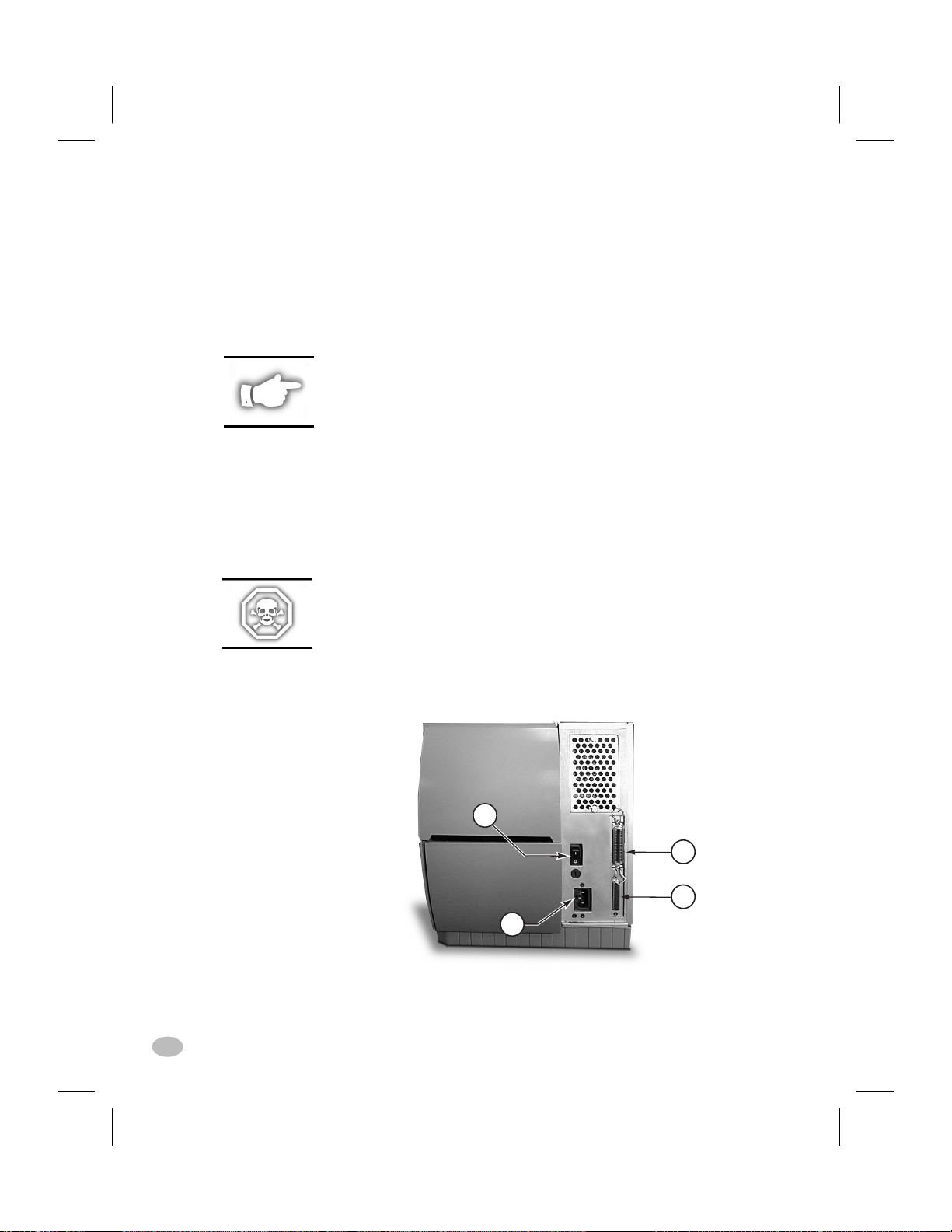
Communications
Refer to Figure 1. The Z Series™ printer comes standard with both an
Electronics Industries Association (EIA) RS-232 serial data interface(a)
and a bi-directional parallel interface(b) compliant with the IEEE1284
standard. The serial interface is also configured for both RS-422/
RS-485 single drop and RS-485 multi-drop communication modes.
NOTE: You must supply the interface cable for your application. See
Appendix B of this manual for specific cable requirements.
Printer Power
The Power Supply in the Z Series™ printer automatically detects the
applied line voltage and works in the 90 to 265 VAC range.
Refer to Figure 1. The AC Power Cord must have a three-prong female
connector on one end which plugs into the mating connector(c) at the
rear of the printer. If a power cable was not included with your printer,
refer to Appendix C at the back of this guide.
WARNING!! For personnel and equipment safety, always use
a three-prong plug with an earth ground connection to the
AC Power Source.
Refer to Figure 1. Insure that the AC Power ON/OFF Switch(d) is in
the OFF (O) position before connecting the AC Power cord to a nearby
electrical outlet.
d
c
Figure 1. Printer Rear View
2 Z Series™ User’s Guide
b
a
H:...uspiran2.vp
Mon Jun 22 10:28:46 1998
10
Page 11

Color profile: Disabled
Composite Default screen
Printer Configuration
Z Series™ Configuration
The Z Series™ printer will have one of two different styled front panels. The deluxe front panel contains an LCD (Liquid Crystal Display),
but the standard front panel does not. With the deluxe front panel, the
LCD displays the parameters during the configuration process. For
those printers with the standard front panel, two banks of eight miniature switches located inside the printer’s front panel access door are
used when configuring the printer.
Communications Parameters
The Z Series™ printer is equipped with both serial data and parallel
data communication interfaces. This permits two sources to send label
formats to the printer.
The first source to send a “Start of Label Format” command controls
the printer. The printer will send a “printer busy” command to the
second source to inhibit data transmission.
The serial interface is factory preset to match the typical PC environment with RS232 communication:
9600 Baud, 8 Data Bits,
No Parity, Xon/Xoff Handshaking.
If you need to change your printer’s serial communications settings to
match those of your host computer, refer to Appendix A. If you do not
know the settings of your host computer, refer to the instruction manual
provided with the computer or your software application.
See Appendix B of this guide for specific data communication cable
requirements.
The printer automatically senses if a parallel communications cable is
connected from your host computer.
Z Series™ User’s Guide 3
H:...uspiran2.vp
Thu Jun 18 15:51:22 1998
11
Page 12
Color profile: Disabled
Composite Default screen
Operating Modes
When shipped from the factory, the printer is preset to the most commonly used modes of operation:
Tear-Off Mode, Thermal Transfer Printing,
Die-Cut Media, Serial Port RS-232 Communications.
Refer to Appendix A to configure the parameters for the following:
n
Options, such as Power Rewind/Power Peel, Value Peel,
or Cutter
n
Operating Modes
n
Print Darkness
n
Label Tear-Off/Cut-Off Position
n
Image Position on the label
4 Z Series™ User’s Guide
H:...uspiran2.vp
Thu Jun 18 15:51:22 1998
12
Page 13
Color profile: Disabled
Composite Default screen
Media & Ribbon Loading
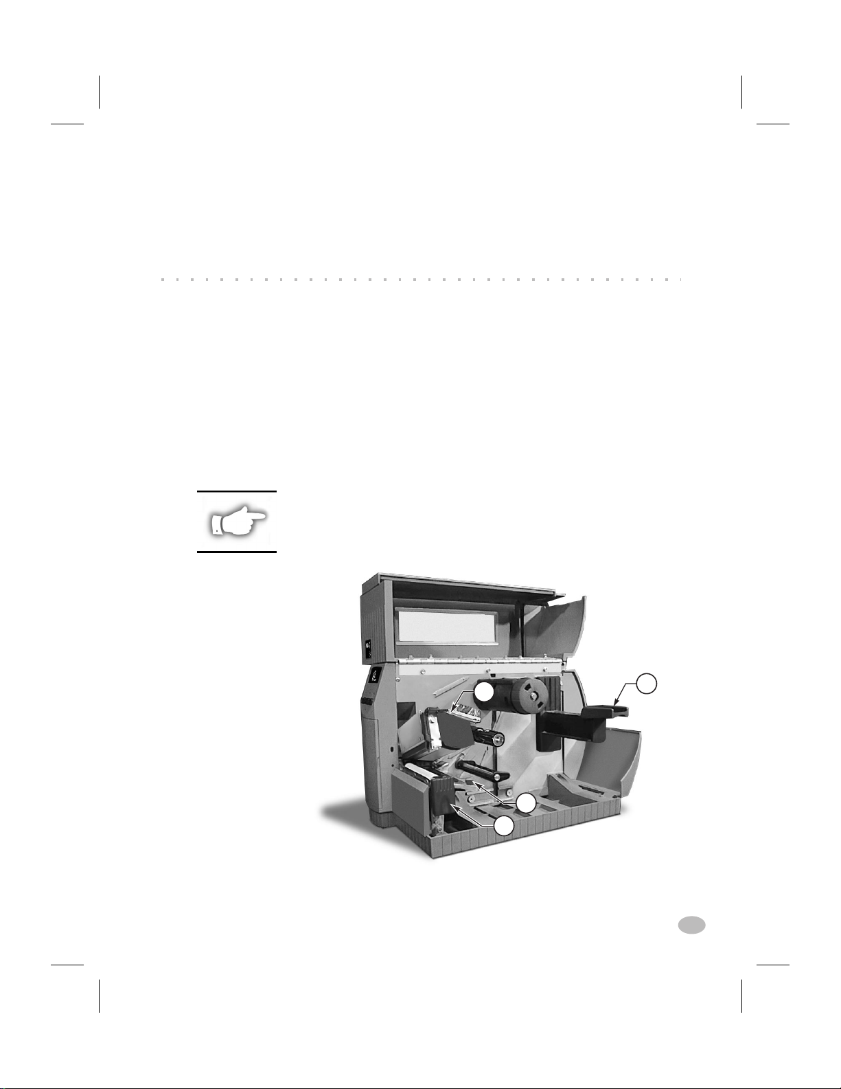
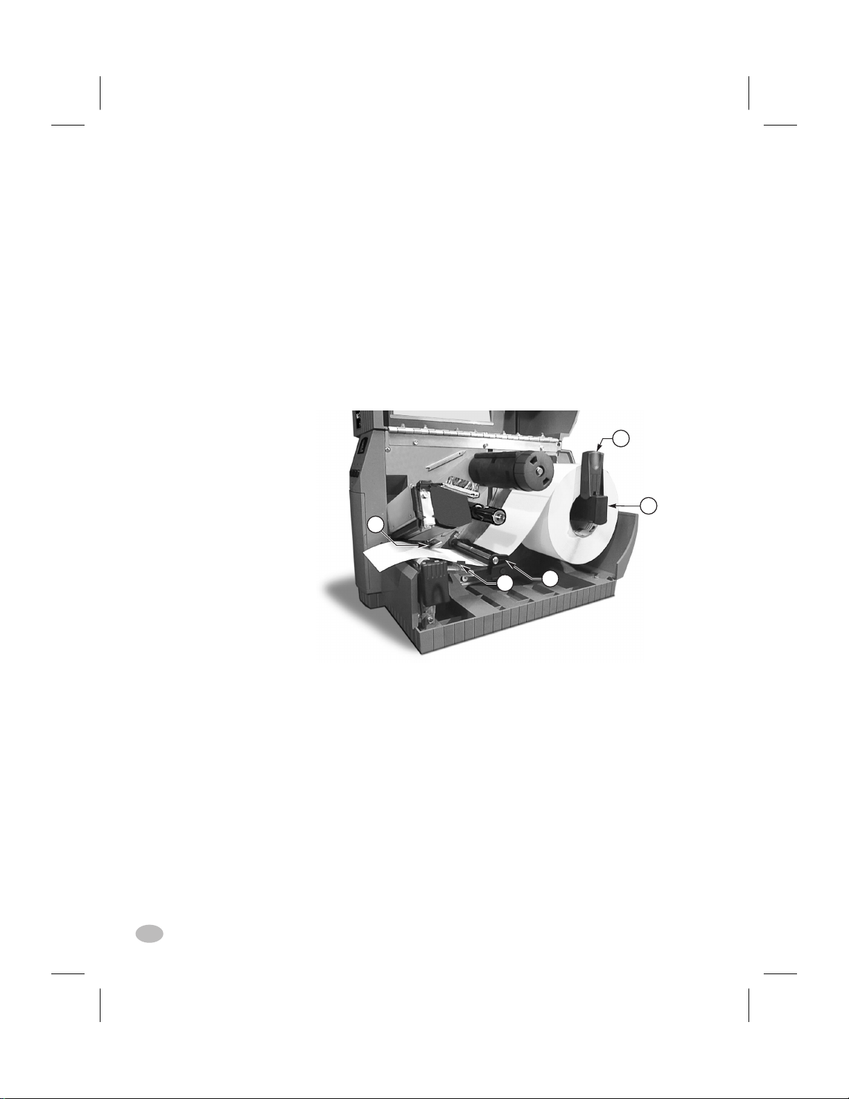
Loading Media
To load media, refer to Figure 2.
1. Raise the media cover.
2. Press the Printhead Open Lever(e).
[The Printhead Assembly(f) automatically springs up.]
3. Fold down the Media Supply Guide(g) and slide it out as far from
the printer frame as possible.
4. Slide the Media Guide(h) out as far from the printer frame as pos-
sible.
5. Determine the type of media required for your application and fol-
low the roll media or fanfold media loading procedure.
NOTE: If your printer has either the Power Rewind/Power Peel, Value
Peel, or Cutter option installed, refer to the Options section for media
loading instructions.
f
g
h
e
Figure 2. Loading Media
H:...uspiran2.vp
Thu Jul 02 09:48:43 1998
Z Series™ User’s Guide 5
13
Page 14
Color profile: Disabled
Composite Default screen
Roll Media Loading
To load roll media, refer to Figure 3.
1. Place the roll of media on the Media Supply Hanger(i) and push it
on all the way.
2. Fold the Media Supply Guide(g) up and slide it against the outer
edge of the media roll.
3. Feed the media under the Media Spindle(j), under the Ribbon Sen-
sor(k), and out the front of the printer.
4. Slide the Media Guide(h) in until it is against the outer edge of the
media.
5. Close the Printhead Assembly and the Media Cover, or continue to
"Loading Ribbon".
g
i
k
h
j
Figure 3. Roll Media Loading
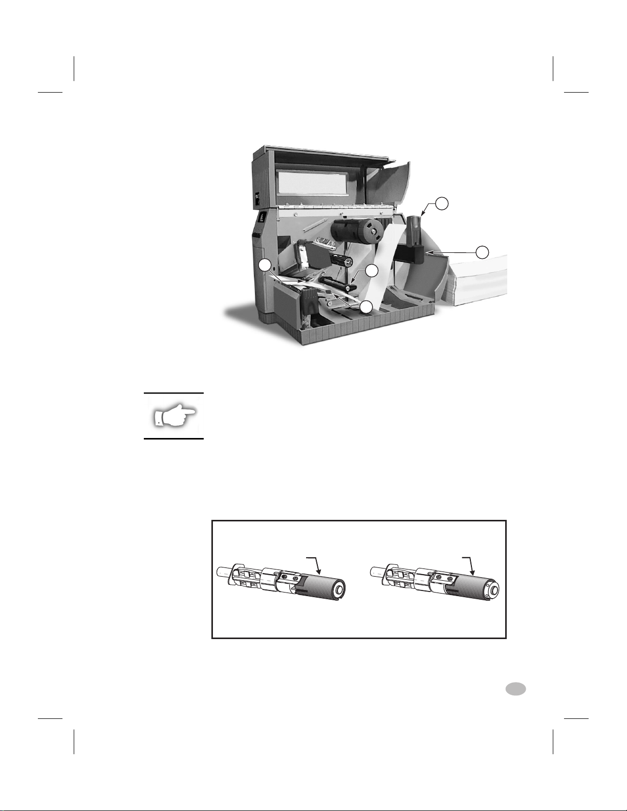
Fanfold Media Loading
To load fanfold media, place the media behind the printer and refer to
Figure 4.
1. Pass the fanfold media over the Media Supply Hanger(i).
2. Fold the Media Supply Guide(g) up and slide it against the outer
edge of the media.
3. Feed the media under the Media Spindle(j), under the Ribbon Sen-
sor(k), and out the front of the printer.
4. Slide the Media Guide(h) against the outer edge of the media.
5. Close the Printhead Assembly and the Media Cover, or continue to
"Loading Ribbon".
6 Z Series™ User’s Guide
H:...uspiran2.vp
Thu Jul 02 09:48:45 1998
14
Page 15
Color profile: Disabled
Composite Default screen
g
i
k
j
h
Figure 4. Fanfold Media Loading
Loading Ribbon
NOTE: The Ribbon Supply Spindle in your printer may be a
"Dual-Tension" variety. Most applications require the spindle to be in the
"Normal" position. The "Low-Tension" position is recommended only when
wide ribbons are used and normal tension hampers the ribbon movement.
To place this spindle in the "Normal" position, firmly pull out on the
Spindle End-Cap until it clicks into place as shown in Figure 5a. To place
the spindle in the "Low-Tension" position, firmly push in on the Spindle
End-Cap until it clicks into place.
SPINDLE END-CAP
EXTENDED
Normal Position
Figure 5a. Ribbon Supply Spindle Positioning
SPINDLE END-CAP
RETRACTED
Low Tension Position
H:...uspiran2.vp
Thu Jul 02 09:48:48 1998
Z Series™ User’s Guide 7
15
Page 16
Color profile: Disabled
Composite Default screen
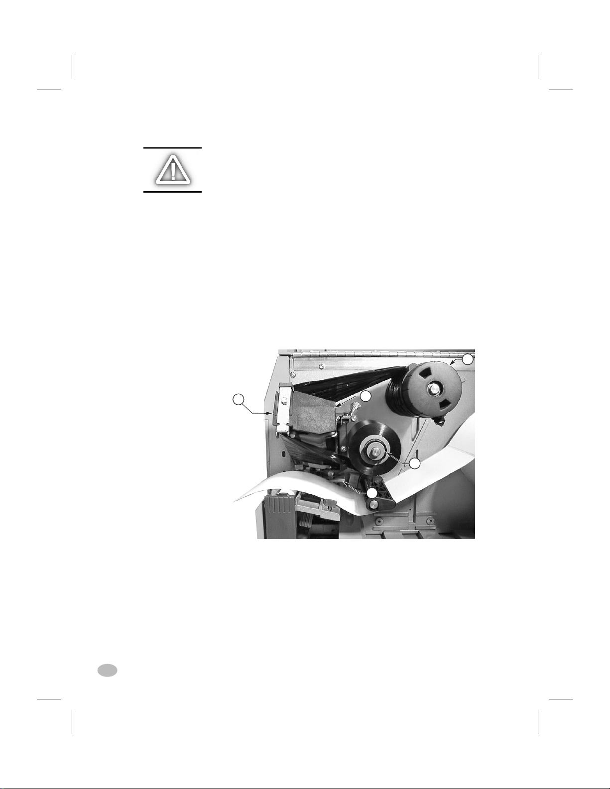
Loading the Ribbon
CAUTION: Always use ribbon that is wider than the media. The
smooth backing of the ribbon protects the printhead from wear.
(For Direct Thermal printing, do not load ribbon in the printer.)
To load ribbon, refer to Figures 5a and 5b.
1. Place the roll on the Ribbon Supply Spindle(l) and push it on all
the way.
2. Pull the end of the ribbon over the Ribbon Sensor(k), under the
Printhead assembly(f), and up over the Ribbon Guide Plate(m).
3. Wind the ribbon onto the Take-up Spindle(n) for several turns in a
clockwise direction.
4. As you close the Printhead Assembly, keep the ribbon snug and
free of wrinkles, and in line with the guide mark near the left edge
of the Ribbon Guide Plate.
n
m
f
l
k
Figure 5b. Ribbon Loading
Removing Ribbon
To remove the ribbon, turn the Release Knob on the end of the Take-up
Spindle(n) counterclockwise and slide the ribbon off the Spindle.
8 Z Series™ User’s Guide
H:...uspiran2.vp
Thu Jul 02 09:48:50 1998
16
Page 17

Color profile: Disabled
Composite Default screen
Media Sensor Positioning
Media Sensor Operation
When the printer is turned ON, a Power ON Self Test is performed
which checks the status of the electronic system and controls within the
printer. Additional operating parameters are determined by the type of
media being used and the position of the Media Sensor located behind
the Platen and under the media.
Non-Continuous (Labels, Notched Tags) Media
This type of media has some type of physical characteristic (notch,
black mark, gap between die-cut labels, etc.) which indicates the startof-label position. The Media Sensor must be properly positioned to
sense these indicators.
Continuous Media
Continuous media typically does not contain start-of-label indicators.
Label length must be specified by commands sent to the printer.
If you are using ZPL II, include a Label Length (^LL) command in
each label format you send to the printer (refer to your ZPL II Programming Guide). If you are using other software to drive your printer, refer
to the instructions provided with that software.
Media Sensor Position
1. To properly position the Media Sensor(o), refer to Figure 6.
2. With the Printhead Assembly open, turn the AC Power ON
3. Look through the side of the print mechanism and locate the
Media Sensor Positioning Lever(p).
4. (non-continuous media - labels, notched tags) Move the lever
across the width of the media to position the sensor in line with the
start-of-label indicator (notch, black mark, gap between die-cut
labels, etc). The glow of the red LED through the media can help
to accurately position the sensor.
(continuous media - no notch or opening to sense) Position the
H:...uspiran2.vp
Thu Jun 18 15:54:02 1998
Z Series™ User’s Guide 9
17
Page 18
Color profile: Disabled
Composite Default screen
sensor anywhere under the media so that an “Out-of-Media” condition will still be sensed.
5. Insure the media and ribbon are properly positioned within the
print mechanism. then close the Printhead Assembly.
6. Close the printer’s media cover, then turn the printer power OFF.
o
Figure 6. Sensor Positioning
Printer Operational Check
1. To insure proper setup and to check the initial printer configura-
tion, press and hold the CANCEL key while turning the printer
power ON. (Release the CANCEL key once the front panel indica-
tors begin to turn OFF.)
2. After an initial time period when the Power ON Self Test is per-
formed, the printer will feed out media while calibrating the label
length, then print a configuration label.
3. Check the current configuration printed on the label and note any
parameters which must be changed to insure the printer fits your
application. For information on changing the configuration for
your specific application, refer to Appendix A.
A visual check of the label also provides an indication of the print quality. Media width and media thickness vary from one application to the
10 Z Series™ User’s Guide
p
H:...uspiran2.vp
Thu Jun 18 15:54:04 1998
18
Page 19

Color profile: Disabled
Composite Default screen
next. To maintain proper print quality, refer to the Care & Adjustments
section later in this guide.
Figure 7 illustrates a properly loaded Z Series™ printer. For loading
media and ribbon in printers with the Power Rewind/Power Peel, Value
Peel or Cutter options, see the Options section later in this guide.
H:...uspiran2.vp
Thu Jun 18 15:54:07 1998
Figure 7. Printer Ready for Operation
Z Series™ User’s Guide 11
19
Page 20

Color profile: Disabled
Composite Default screen
12 Z Series™ User’s Guide
20
H:...uspiran2.vp
Thu Jun 18 15:54:08 1998
Page 21

Color profile: Disabled
Composite Default screen
Printer Operation
Operator Interface
The Z Series™ family of printers features either a standard or deluxe
front panel. The deluxe front panel features a Liquid Crystal Display
(LCD) that provides both printer status information and configuration
option menus. This section of the user’s guide presents information
which is common to both printer front panels. Refer to Figures 8 and 9
to locate the keys and LEDs discussed in this section.
Front Panel Keys
Feed Key
The FEED key forces the printer to feed one blank label. If you press
the FEED key while the printer is idle or paused, a blank label is fed
immediately. If you press the FEED key while the printer is printing,
one blank label is fed after the completion of the current batch of
labels. Once the blank label has been fed, pressing the FEED key again
will feed a second label.
H:...uspiran2.vp
Thu Jun 18 15:54:51 1998
Pause Key
The PAUSE key stops and restarts the printing process. The first time
you press the PAUSE key, any partially printed label is completed; then
the printing process is stopped. If the printer is idle when you press the
PAUSE key, no new print requests are accepted. Press the PAUSE key
a second time to resume the printing process.
Cancel Key
The CANCEL key only functions when the printer is paused. When
you press the CANCEL key, the label format that is currently printing
is canceled. If no label format is printing, then the next one to be
printed is canceled. If there are no label formats stored in the printer
and waiting to be printed, the CANCEL key is ignored.
If you press the CANCEL key for an extended period of time (more
than 3 seconds) the printer performs a “cancel all formats” operation.
The printer discards all of the label format data it has received, and
returns to the idle state.
Z Series™ User’s Guide 13
21
Page 22
Color profile: Disabled
Composite Default screen
Front Panel LEDs
LEDs on the front panel are a quick indication of the printer's status.
The LEDs listed below are common to all Z Series™ printers .
POWER LED
The POWER LED is always ON when the printer is turned ON.
DATA LED
The DATA LED is normally OFF. When data is received, the LED acts
as follows:
n
SLOW BLINK - Printer is unable to accept more data
from the host
n
FAST BLINK - Printer is receiving data
n
LED ON - No data being received - data processing
or printing still occurring.
The DATA LED will also blink once when the CANCEL key is
pressed and a format is successfully canceled.
ERROR LED
The ERROR LED is normally OFF. When an error occurs that causes
an interruption in the printing process, the LED acts as follows:
n
SLOW BLINK - Ribbon In Warning, Under Temp
Warning, or Over Temp Error
n
FAST BLINK - Printhead Open
n
LED ON - Media Out, Ribbon Out, or Cutter Errors
With the Deluxe Front Panel, the type of error will also be visible on
the Liquid Crystal Display.
PAUSE LED
The PAUSE LED is normally OFF. When the LED is ON it indicates
the printer has stopped all printing operations. If the printer is printing
when a PAUSE condition is requested, the LED turns ON at the end of
the current label.
In the Peel operating mode, the PAUSE LED will blink when the label
is available for removal. No printing occurs when the printer is in the
Peel mode of operation and the Peel option is not installed.
Additional Front Panel Controls
The front panel door conceals the configuration and setup keys and/or
switches inside. Refer to the Printer Configuration section of this guide
to configure the printer for your application.
14 Z Series™ User’s Guide
22
H:...uspiran2.vp
Thu Jun 18 15:54:52 1998
Page 23
Color profile: Disabled
Composite Default screen
Figure 8. Standard Front Panel
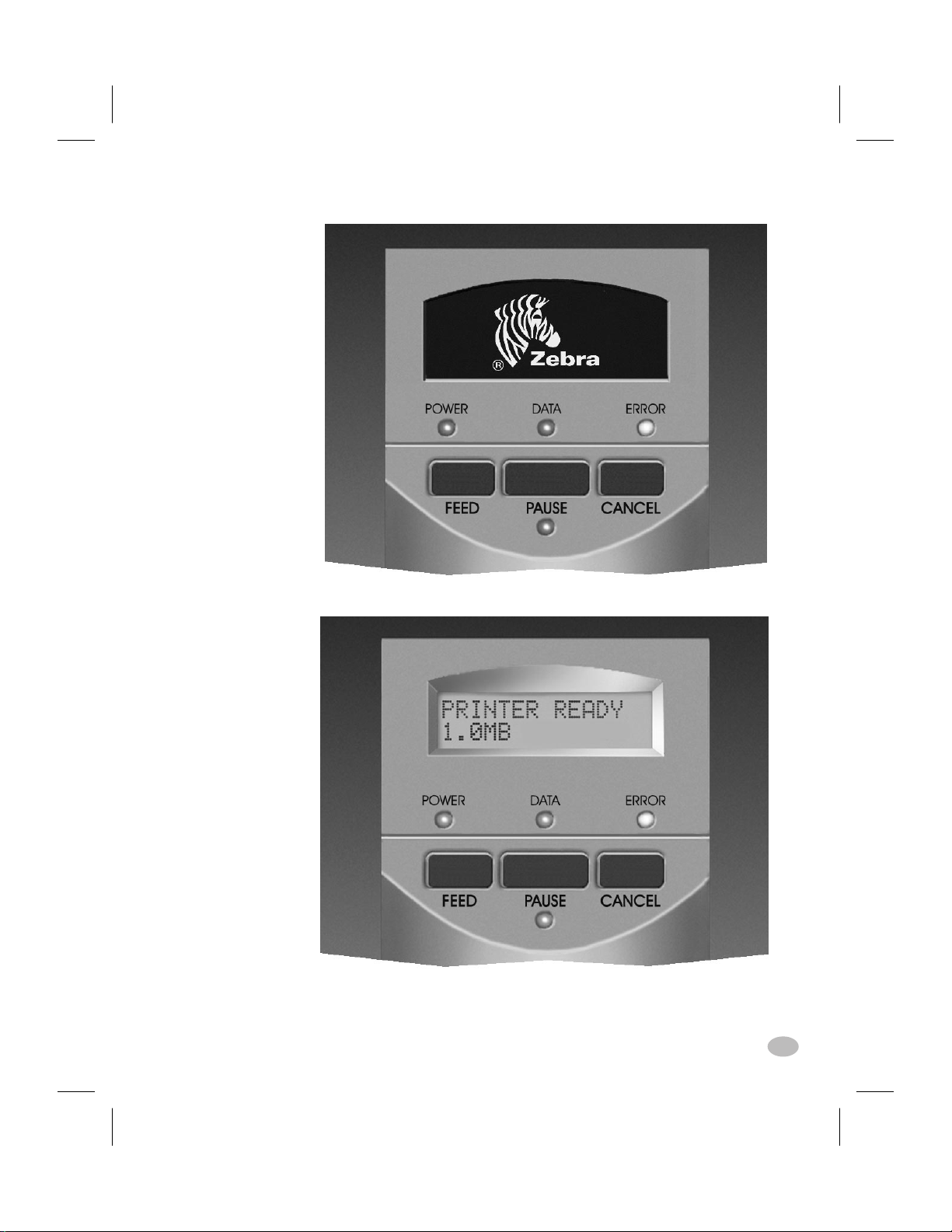
Figure 9. Deluxe Front Panel
H:...uspiran2.vp
Thu Jun 18 15:54:53 1998
Z Series™ User’s Guide 15
23
Page 24

Color profile: Disabled
Composite Default screen
16 Z Series™ User’s Guide
24
H:...uspiran2.vp
Thu Jun 18 15:54:55 1998
Page 25

Color profile: Disabled
Composite Default screen
Media Calibration
Auto-Calibration
The auto-calibration of the Z Series™ printer occurs at power ON and
each time the printer recovers from error conditions such as media errors, ribbon errors, and printhead open errors. In the process of clearing
an error, open and close the printhead then take the printer out of
PAUSE. The printer will begin the auto-calibration process if all errors
have been cleared.
The printer automatically determines the label length, and media and
ribbon sensor settings.
When non-continuous media is sensed, the calibration process is followed by the label length calculation. Once the label length is determined, the media feeds to the rest position and stops.
The results of this calibration are stored in the printer's memory and are
retained even if printer power is removed. These parameters remain in
effect until the next calibration is performed.
Calibration Control
The auto-calibration process will not take place if the ZPL command or
the deluxe front panel setting for “Media Power Up” or “Head Close”
is set to either “feed” or “no motion.” In these cases, the printer assumes the media is correctly positioned and starts printing without calibrating.
As long as the printhead is closed, a calibration may be performed.
Calibration may clear error conditions that prevent media movement.
Ribbon and media error conditions are cleared by calibration, unless an
out-of-ribbon or out-of-media condition exists.
NOTE: If your printer has the standard front panel, the Calibration
function is controlled by a ZPL II command sent from the host computer.
No front panel calibration control is available.
H:...uspiran2.vp
Thu Jun 18 15:55:17 1998
Z Series™ User’s Guide 17
25
Page 26

Color profile: Disabled
Composite Default screen
18 Z Series™ User’s Guide
26
H:...uspiran2.vp
Thu Jun 18 15:55:18 1998
Page 27
Color profile: Disabled
Composite Default screen
Care & Adjustments
Cleaning
CAUTION: Use only the cleaning agents indicated. Zebra Technologies Corporation will not be responsible for damage caused by any
other cleaning materials used on the Z Series™ printer.
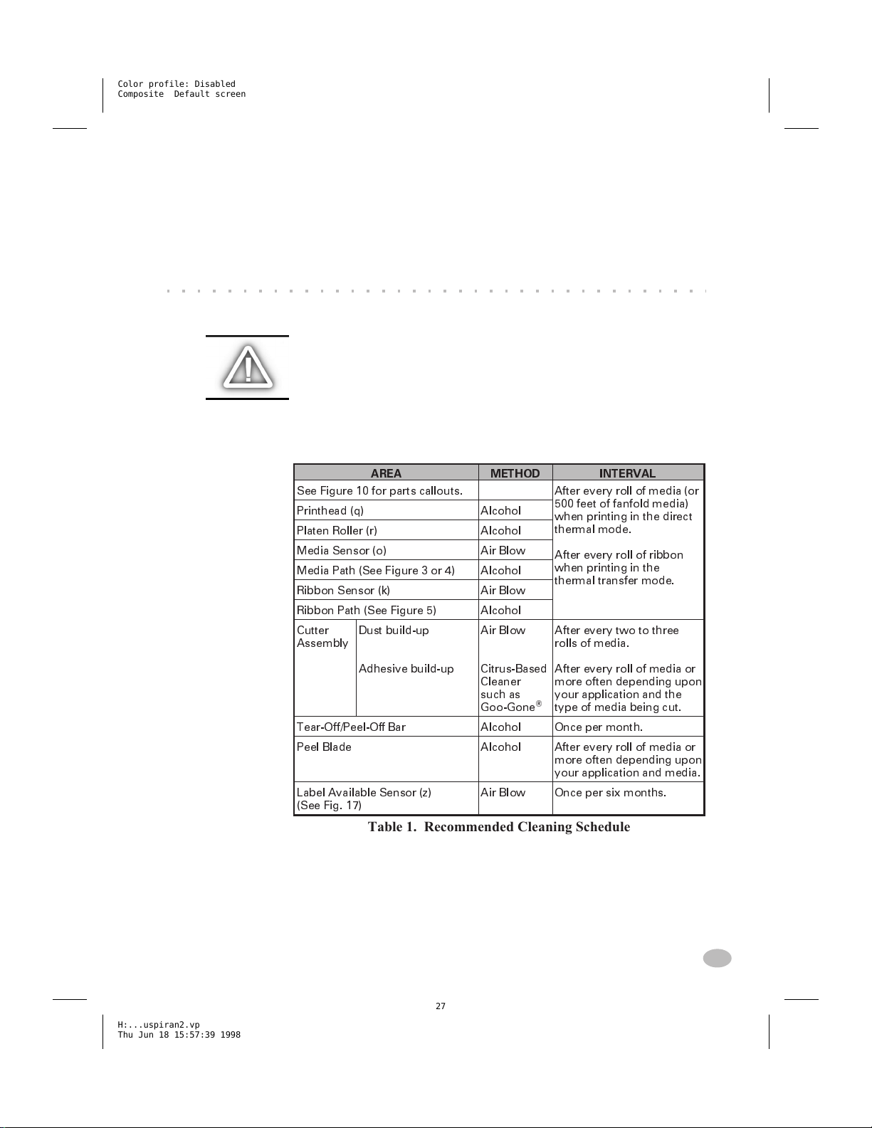
Table 1 provides a recommended cleaning schedule. Cleaning Swabs
saturated with 70% Isopropyl Alcohol are available from your Zebra
distributor as a Preventive Maintenance Kit (part # 01429).
AREA METHOD INTERVAL
See Figure 10 for parts callouts. After every roll of media (or
Printhead (q) Alcohol
Platen Roller (r) Alcohol
Media Sensor (o) Air Blow
Media Path (See Figure 3 or 4) Alcohol
Ribbon Sensor (k) Air Blow
Ribbon Path (See Figure 5) Alcohol
Cutter
Assembly
Dust build-up
Air Blow
500 feet of fanfold media)
when printing in the direct
thermal mode.
After every roll of ribbon
when printing in the
thermal transfer mode.
After every two to three
rolls of media.
H:...uspiran2.vp
Thu Jun 18 15:57:39 1998
Adhesive build-up
Tear-Off/Peel-Off Bar Alcohol Once per month.
Peel Blade Alcohol After every roll of media or
Label Available Sensor (z)
(See Fig. 17)
Citrus-Based
Cleaner
such as
Goo-Gone
Air Blow Once per six months.
After every roll of media or
more often depending upon
your application and the
®
type of media being cut.
more often depending upon
your application and media.
Table 1. Recommended Cleaning Schedule
Cleaning the Exterior
The exterior of the Z Series™ printer may be cleaned with a lint-free
cloth. Do not use harsh, abrasive cleaning agents or solvents. If necessary, a mild detergent or desktop cleaner may be used sparingly.
Z Series™ User’s Guide 19
27
Page 28

Color profile: Disabled
Composite Default screen
Cleaning the Interior
Remove any accumulated dirt and lint from the interior of the printer
using a soft bristle brush and/or vacuum cleaner.
Cleaning the Printhead and Platen Roller
Inconsistent print quality, such as voids in the bar code or graphics,
may indicate a dirty printhead. For best results, perform the following
cleaning procedure after every roll of ribbon.
NOTE: The printer can remain ON while you are cleaning the
printhead. In this way all label formats, images, and all temporary
parameter settings stored in the printer's internal memory will be saved.
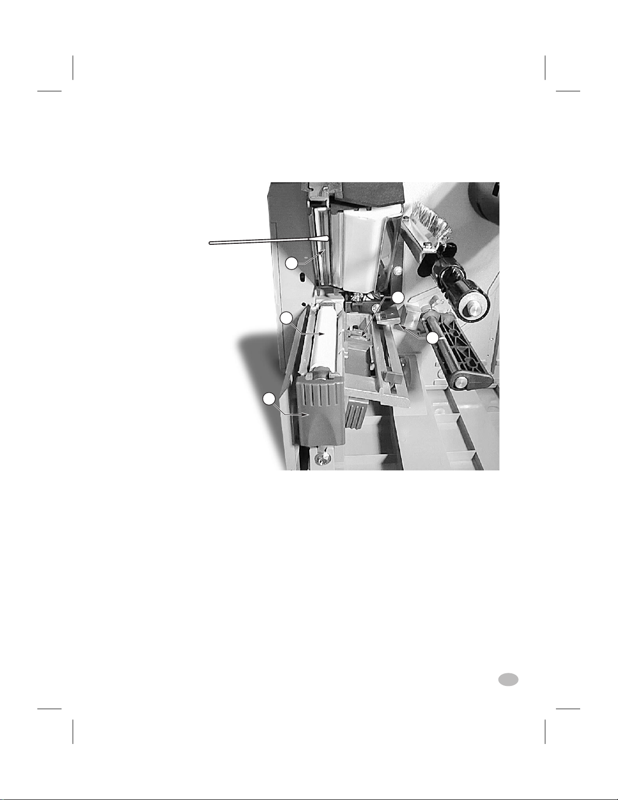
To clean the printhead, refer to Figure 10 and follow these steps:
1. Open the Media Compartment Door.
2. Open the Printhead Assembly by pressing the Printhead Open
Lever(e).
3. Remove the media and ribbon (if present).
4. Raise the Printhead Assembly by hand and, using a cleaning swab
soaked in alcohol, wipe along the printhead(q) print elements from
end to end. (The print elements are located within the brown strip
just behind the chrome strip on the printhead.) Allow a few seconds for the solvent to evaporate.
5. Rotate the platen roller(r) and clean thoroughly with a cleaning
swab soaked in alcohol.
6. Brush/vacuum any accumulated paper lint and dust away from the
media and ribbon paths.
7. Reload media and ribbon, close the printhead assembly, close the
Media Compartment Door, and continue printing.
Cleaning the Sensors
Refer to Figure 10. The Media Sensor(o) and Ribbon Sensor(k) should
be cleaned on a regular basis to ensure proper operation of the printer.
For printers with the Value Peel option or the Power Rewind/Power
Peel option installed refer to Figure 17 and clean the Label Available
Sensor(z). Brush or vacuum any accumulated paper lint and dust away
from the sensors.
20 Z Series™ User’s Guide
28
H:...uspiran2.vp
Thu Jun 18 15:57:40 1998
Page 29
Color profile: Disabled
Composite Default screen
q
o
r
k
e
Figure 10. Printhead and Platen Roller Cleaning
Z Series™ User’s Guide 21
H:...uspiran2.vp
Thu Jun 18 15:57:44 1998
29
Page 30

Color profile: Disabled
Composite Default screen
Cleaning the Cutter Module
(For printers equipped with the Cutter option.)
The Cutter Module requires periodic cleaning to remove paper dust
and gummed label residue. If labels are not being cut properly, or if the
cutter jams with labels, this is an indication that the cutter probably
needs cleaning. The cleaning frequency depends on your application
and the type of media you use.
When the stationary cutter blade and the v-shaped moveable cutter
blade become gummed up with label adhesive and/or paper debris,
clean them according to the procedure below. Steps 4 and 5 detail the
method of removal of the Cutter Module from the printer. This portion
of the procedure will only be required when there is an extremely
heavy buildup of adhesive residue.
Refer to Figure 11 during the following cleaning procedure.
1. Turn the AC power off and unplug the printer power cord.
2. Open the Media Door and press the Printhead Open Lever to raise
the Printhead Assembly.
3. Remove the thumb screw and lift off the Finger Guard (and Catch
Tray if used).
4. Usea3mmAllen Wrench to remove the cutter mounting screw.
5. Carefully lift the Cutter Module up and away from the printer.
6. Remove all paper and label residue from the cutter blades and
housing.
WARNING!! The cutter blades are very sharp. Take great
care in the following step to insure personal safety.
7. Use cotton swabs soaked with a citrus-based cleaner (Goo Gone)
to remove all adhesive residue from the cutter blades. (While
cleaning, rotate the cutter motor to access the entire length of the
moveable blade.)
8. If adhesive has accumulated on the Platen and the Tear/Peel Bar,
clean these areas in a similar manner.
9. When the cleaning is completed, reinstall the Cutter Module, the
Finger Guard and the Catch Tray, if used.
10. Install media, then close and latch the Printhead Assembly.
11. Connect the printer to an AC power source, and turn the printer on.
12. The printer should be ready to print and cut labels once again.
22 Z Series™ User’s Guide
30
H:...uspiran2.vp
Thu Jun 18 15:57:44 1998
Page 31

Color profile: Disabled
Composite Default screen
H:...uspiran2.vp
Thu Jun 18 15:57:54 1998
Figure 11. Cutter Cleaning
NOTE: Disassembly of the Cutter module should only be performed by a
Service Technician.
Z Series™ User’s Guide 23
31
Page 32

Color profile: Disabled
Composite Default screen
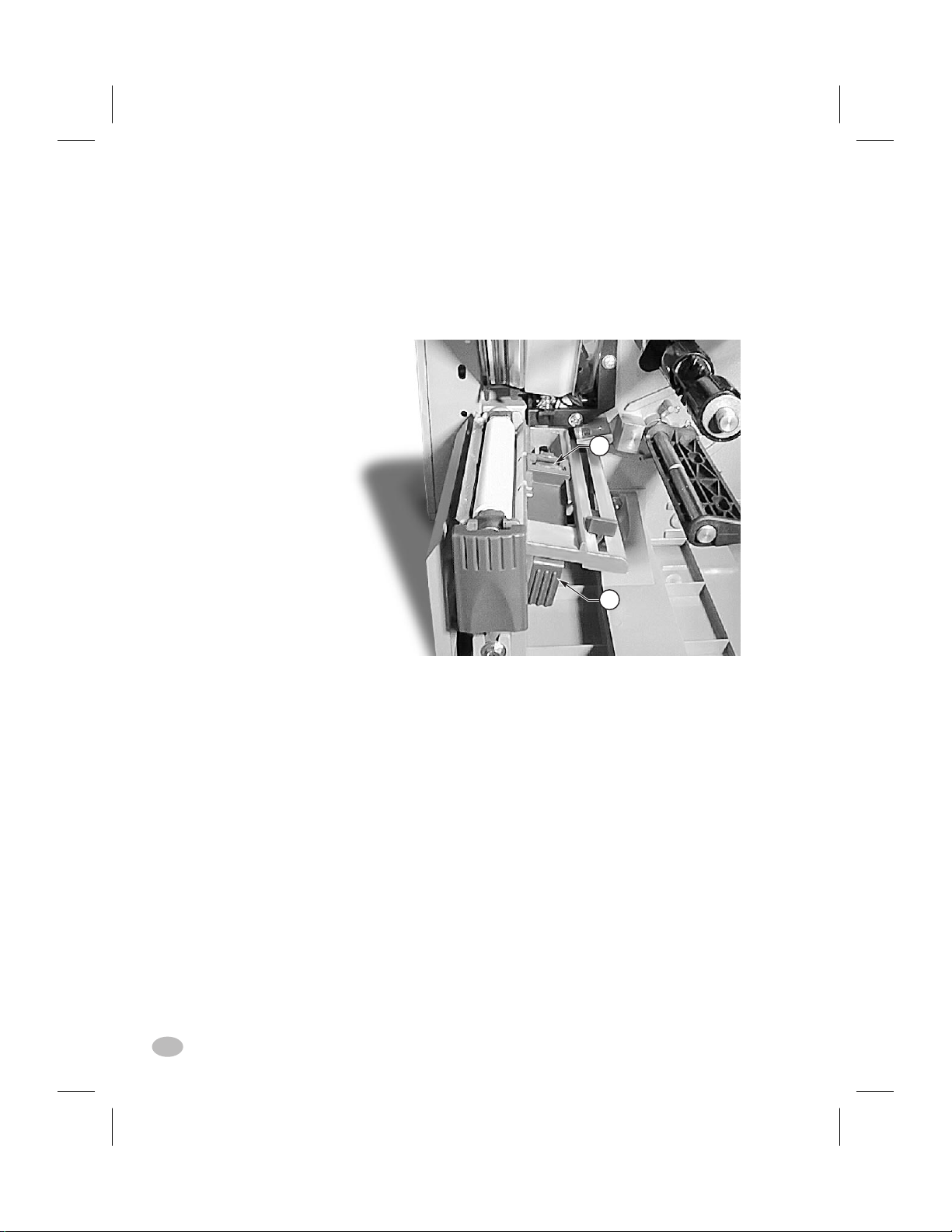
Cleaning the Peel Blade
(For printers equipped with the Value Peel or Power Peel option.)
1. Open the Media Door and press the Printhead Open Lever to raise
the Printhead Assembly.
2. Refer to Figure 12. Open the Peel Mechanism by gently lifting up
on the Media Plate and pivoting it toward you.
3. Refer to Figure 12. The primary area requiring cleaning is the
backside of the Separator Bar.
4. Remove the major portion of the accumulated adhesive by pressing
the sticky side of a blank label against the adhesive and lifting it
away. (Do this step repeatedly until most of the adhesive is gone.)
5. Aggressively wipe the area with a cloth soaked in alchohol to
remove any residual adhesive.
6. Move the media backing material out of the way to allow inspec-
tion of the Tear/Peel Bar.
7. If any adhesive has accumulated, repeat the cleaning process on
the Tear/Peel Bar.
8. When the cleaning process is completed, align the media backing
material and return the Media Plate to the operating position.
9. Align the ribbon (if used) as you close and latch the Printhead
Assembly.
10. Close the Media Door and resume operation.
Figure 12. Peel Blade Cleaning
24 Z Series™ User’s Guide
32
H:...uspiran2.vp
Thu Jun 18 15:57:59 1998
Page 33

Color profile: Disabled
Composite Default screen
Lubrication
CAUTION! No lubricating agents of any kind should be used on this
printer! Some commercially available lubricants, if used, will damage
the finish and the mechanical parts inside the printer.
Printhead Pressure Adjustment
Printhead pressure is adjustable to insure maximum print quality. Refer
to Figure 13 and rotate the Pressure Adjustment Dials(s & t) clockwise
to increase the pressure or counterclockwise to decrease the pressure of
the printhead against the ribbon and/or media.
The amount of pressure required varies from one application to the next
and is determined by the type and thickness of the media as well as the
media width.
If using narrow media, you may need to reduce the pressure applied by
the right hand dial to minimize the pressure over the unused printhead
area.
H:...uspiran2.vp
Thu Jun 18 15:58:03 1998
s
t
Figure 13. Printhead Pressure Adjustment
Z Series™ User’s Guide 25
33
Page 34

Color profile: Disabled
Composite Default screen
Power Rewind/Power Peel
Media Alignment
(For printers equipped with the Power Rewind/Power Peel option.)
An adjustment to the Media Alignment Spindle allows the user to insure that the media or backing material is properly winding onto the
Take-up Spindle.
Refer to Figure 14. Turn the adjustment dial(v) clockwise to align the
media/backing material more to the left.
Turn the dial counterclockwise to align the media/backing material to
align more to the right.
v
Figure 14. Power Rewind/Power Peel Media Alignment
26 Z Series™ User’s Guide
34
H:...uspiran2.vp
Thu Jun 18 15:58:05 1998
Page 35

Color profile: Disabled
Composite Default screen
Printer Options
LCD Display (Deluxe Front Panel)
The Z Series™ printers include the option of replacing the standard
front panel with a deluxe front panel containing a Liquid Crystal
Display (LCD).
The LCD shows several types of information.
n
When the printer completes its Power ON Self Test, the LCD
displays an “idle” message.
PRINTER READY
1024K Vxx.x.x
n
While a format is printing, a label counter is displayed.
PRINTING
1 OF 99999999
n
The LCD also indicates memory conditions when they occur.
CREATING BITMAP BUILDING FORMAT
STORING GRAPHIC STORING FORMAT
STORING BITMAP STORING FONT
n
The LCD also displays an error message when an error occurs.
HEAD OPEN PAPER OUT
RIBBON OUT RIBBON IN
BUFFER OVERFLOW CUTTER JAMMED
HEAD COLD HEAD TOO HOT
OUT OF MEMORY
NOTE: When an error condition is corrected, the top line of that error
display indicates “ERROR CLEARED.” Once all of the errors have been
cleared, press the PAUSE key to resume printing.
n
When configuring the printer’s operating parameters, the
configuration menu is displayed on the LCD. Refer to Appendix A
for printer configuration parameters.
H:...uspiran2.vp
Wed Jul 08 11:38:49 1998
Z Series™ User’s Guide 27
35
Page 36

Color profile: Disabled
Composite Default screen
Power Rewind/Power Peel Option
The Z Series™ printer supports a rewind option, with the capability of
rewinding an entire roll of printed labels (Rewind mode) or backing
material only (Peel mode). This option is available as both a factory
installed feature and a field-installable kit.
Label Movement in Rewind Mode
In the Rewind mode, labels are printed and fed forward in a continuous
sequence. As printing continues, the media is wound onto the Take-Up
Spindle.
Label Movement in Peel Mode
In the Peel mode, when a label is completely printed, the printer feeds
the label forward to the take-label position. The label hangs from the
printer and is held in place by that portion of the label still attached to
the backing material. When the operator removes the label, the printer
moves the next label forward to “pre-peel” a portion of the label from
the backing. The label then backfeeds to be printed. As printing continues, the backing material is wound onto the Take-Up Spindle.
Refer to Appendix A for information on configuring the printer for
either the Power Rewind or Power Peel mode of operation.
g
i
k
w
u
v
h
e
j
y
x
Figure 15. Media Loading (Power Rewind Option)
28 Z Series™ User’s Guide
36
H:...uspiran2.vp
Wed Jul 08 11:38:51 1998
Page 37

Color profile: Disabled
Composite Default screen
Media Loading
Refer to Figure 15 (Power Rewind) or Figure 16 (Power Peel) while
loading media.
1. Place the roll of media on the Media Supply Hanger(i) and push it
on all the way.
2. Fold the Media Supply Guide(g) up and slide it against the outer
edge of the media roll.
3. Press the Printhead Open Lever(e) and raise the Printhead Assembly.
4. Feed the media under the Media Spindle(j), under the Ribbon Sen-
sor(k), and out the front of the printer.
5. Slide the Media Guide(h) in until it is against the outer edge of the
media.
6. Pull about three feet of media through the front of the printer.
7. (For Power Rewind) Pass the media down over the Media
Plate(u), through the printer housing, and under the Media Alignment Spindle(v).
(For Power Peel) Lift the Media Plate(u) and rotate it forward.
Remove the labels from the backing material, then pass the backing over the Peel Bar(w), down behind the Media Plate(u), through
the printer housing, and under the Media Alignment Spindle(v).
Return the Media Plate to its operating position.
g
i
k
w
u
v
h
e
j
y
x
Figure 16. Media Loading (Power Peel Option)
H:...uspiran2.vp
Wed Jul 08 11:38:54 1998
Z Series™ User’s Guide 29
37
Page 38

Color profile: Disabled
Composite Default screen
8. Loosen the thumbscrew and slide the Rewind Media Guide(x) out
to the end of the spindle and rotate it to its horizontal position.
9. Place an empty media core on the Rewind Spindle(y), wrap the
media around the core, and turn the spindle counterclockwise to
wind up the excess material.
10. Rotate the Rewind Media Guide to its vertical position, slide it in
against the media, and tighten the thumbscrew that locks it into
position.
11. Go to the “Loading Ribbon” procedure earlier in this guide; then
continue through the “Configuration” and “Media Sensor Positioning” processes.
Media/Backing Removal
1. Loosen the thumbscrew and slide the Rewind Media Guide(x) out
to the end of the spindle and rotate it to its horizontal position.
2. Cut the media/backing material prior to where it winds onto the
Take-up Spindle.
3. Slide the roll of media/backing material from the Take-Up Spindle.
Value Peel Option
The Z Series™ printer also features a Value Peel option, supporting the
Peel-off mode. This option is available as both a factory installed feature and a field installable kit.
Label Movement in Peel Mode
This option does not capture the backing material on a spindle. Instead,
the backing drops down from the front of the printer.
In the Peel mode, when a label is completely printed, the printer feeds
the label forward to the take-label position. The label hangs from the
printer and is held in place by that portion of the label still attached to
the backing material. When the operator removes the label, the printer
moves the next label forward to “pre-peel” a portion of the label from
the backing. The label then backfeeds to be printed.
Refer to Appendix A for information on configuring the printer for the
Value Peel mode of operation.
30 Z Series™ User’s Guide
H:...uspiran2.vp
Wed Jul 08 11:38:54 1998
38
Page 39

Color profile: Disabled
Composite Default screen
Media Loading
Refer to Figure 17 while loading media.
1. Place the roll of media on the Media Supply Hanger(i) and push it
on all the way.
2. Fold the Media Supply Guide(g) up and slide it against the outer
edge of the media roll.
3. Press the Printhead Open Lever(e) and raise the Printhead Assembly.
4. Feed the media under the Media Spindle(j), under the Ribbon Sen-
sor(k), and out the front of the printer.
5. Slide the Media Guide(h) in against the outer edge of the media.
6. Lift the Peel Assembly(u) and rotate it forward, away from the printer.
7. Pull about 12 to 18 inches of backing only down over the edge of
the Peel/Tear Bar(w) and close the printhead.
8. Return the Peel Assembly to its operating position. Insure the Assem-
bly is reseated on the tabs of the Peel/Tear Bar(w), go to the “Loading
Ribbon” procedure earlier in this guide; then continue through the
“Configuration” and “Media Sensor Positioning” processes.
g
w
z
u
k
j
h
e
i
Figure 17. Media Loading (Value Peel-Off Option)
Z Series™ User’s Guide 31
H:...uspiran2.vp
Wed Jul 08 11:38:58 1998
39
Page 40

Color profile: Disabled
Composite Default screen
Cutter Option
The Z Series™ printer also features a cutter option. This option is available as both a factory installed feature and a field installable kit. A label
catch tray is included which holds up to 10 labels up to 6” in length.
Label Movement in Cutter Mode
When the label is completely printed, the printer feeds the media into
the cutter mechanism. The cutter blade is activated and the printer
waits for the cutter mechanism to complete its cycle. After cutting, the
printer backfeeds the media to the rest position or to the start of the
next label if another label is in the print queue. If the cut cycle is not
completed, the printer automatically stops the print cycle and turns the
ERROR LED ON. This will normally identify a cutter jam.
Refer to Appendix A for information on configuring the printer for the
Cutter mode of operation.
Media Loading
Refer to Figure 18 while loading media.
1. Place the roll of media on the Media Supply Hanger(i) and push it
on all the way.
2. Fold the Media Supply Guide(g) up and slide it against the outer
edge of the media roll.
3. Press the Printhead Open Lever(e) and raise the Printhead Assembly.
k
Figure 18. Media Loading (Cutter Option)
32 Z Series™ User’s Guide
40
H:...uspiran2.vp
Wed Jul 08 11:39:02 1998
g
i
h
e
j
Page 41

Color profile: Disabled
Composite Default screen
4. Feed the media under the Media Spindle(j), under the Ribbon Sen-
4. Feed the media under the Media Spindle(j), under the Ribbon Sen-
sor(k), through the Cutter Module, and out the front of the printer.
sor(k), through the Cutter Module, and out the front of the printer.
5. Slide the Media Guide(h) in against the outer edge of the media.
5. Slide the Media Guide(h) in against the outer edge of the media.
6. Go to the “Loading Ribbon” procedure earlier in this guide; then
6. Go to the “Loading Ribbon” procedure earlier in this guide; then
continue through the “Configuration” and “Media Sensor Position-
continue through the “Configuration” and “Media Sensor Positioning” processes.
ing” processes.
H:...uspiran2.vp
Wed Jul 08 11:39:02 1998
Z Series™ User’s Guide 33
41
Page 42

Color profile: Disabled
Composite Default screen
Electronics Options
PCMCIA Option
An optional PCMCIA Port is available for the Z Series™ printer.
This option is available as both a factory installed feature and a field
installable kit.
Access to the PCMCIA port is from the rear of the printer. Optional
PCMCIA Memory Cards will provide non-volatile storage for label
formats, downloadable fonts, graphics files, etc. The content of the
PCMCIA Memory Card is not lost when power is turned OFF.
DRAM Memory Option
A 2 Megabyte memory upgrade is available for the Z Series™ printer
as both a factory installed feature and a field installable kit. This additional memory area can be used to store a higher quantity of label
formats or larger label formats. The content of the DRAM Memory is
lost when power is turned OFF.
This option consists of an electronic memory device which is inserted
into a holder on the Main Logic Board inside the printer.
Flash Memory Option
Two non-volatile memory options (a 1 Megabyte and a 2 Megabyte)
are available for the Z Series™ printer. This additional memory area
can be used to store optional printer fonts, graphic formats, and complete label formats.
34 Z Series™ User’s Guide
42
H:...uspiran2.vp
Wed Jul 08 11:39:02 1998
Page 43

Color profile: Disabled
Composite Default screen
Once the option is installed in the printer, information to be stored in
Flash Memory is downloaded to the printer from the host computer.
A specific ZPLcommand is then sent to the printer which causes the
information to be stored in the Flash Memory. The content of the Flash
Memory is not lost when power is turned OFF.
Communication Options
Ethernet
Ethernet Thinnet and 10BaseT connectivity are available through an
external connection to the parallel port at the rear of the printer.
IPX, LAT, NetBIOS/Net BEUI, TCP/IP protocols are supported with a
data burst rate of 150 KB. HP Bitronics mode is supported to provide
bi-directional high-speed. It is SNMP compatible and supports MIB I,
MIB II and Parallel MIB as well as MPSCON: (NOVELL Netware) PC
console configuration utility IPX.
H:...uspiran2.vp
Wed Jul 08 11:39:02 1998
Z Series™ User’s Guide 35
43
Page 44

Color profile: Disabled
Composite Default screen
36 Z Series™ User’s Guide
44
H:...uspiran2.vp
Wed Jul 08 11:39:02 1998
Page 45

Color profile: Disabled
Composite Default screen
Troubleshooting
Power On Self-Test
A Power On Self Test (POST) is performed each time the printer is
turned ON. During this test, the front panel LEDs will turn ON and
OFF to ensure proper operation. At the end of this self test, only the
POWER LED will remain lit.
Once the Power ON Self Test is complete, the media is advanced to the
proper rest position as determined by the programmed media feed setting. Continuous media is assumed to be at the proper rest position.
Troubleshooting Tables
The following tables provide trouble symptoms, a diagnosis of specific
causes and a recommended action which should result in proper printer
operation.
SYMPTOM DIAGNOSIS ACTION
All LEDs never light. No AC Power applied to
Printer locks up when
running the Power On
Self Test with some or
all LEDs ON.
the printer.
Faulty AC Power Fuse. Refer to Appendix C for
No voltage available
from the internal power
supply.
Printer not configured
properly.
Internal printer failure. Call a Service
Table 2. Power ON Troubleshooting
Ensure the AC Power
cable is connected to
a working voltage
source.
Fuse replacement
procedures.
Call a Service
Technician.
Refer to the PAUSE and
FEED Key Self Test and
reload factory defaults;
then reconfigure the
printer for the
application.
Technician.
H:...uspiran2.vp
Thu Jun 18 16:02:05 1998
Z Series™ User’s Guide 37
45
Page 46

Color profile: Disabled
Composite Default screen
SYMPTOM DIAGNOSIS ACTION
Printer stops, PAUSE
LED ON and ERROR
LED FLASHING Fast.
Printer stops, PAUSE
LED BLINKING.
Printer stops. PAUSE
LED ON and ERROR
LED FLASHING Slow.
Dots missing in printed
area of label.
Loss of printing
registration on labels.
Printhead is not fully
closed.
Malfunctioning
Printhead Open Sensor.
Printer in Peel mode
and no Peel option
installed.
Printhead element is
overheated.
Printhead element bad.
Print quality problems.
Possible Media Sensor
problem.
Close printhead
completely.
Call a Service
Technician.
Change printer
operating mode to
fit application.
Printer resumes printing
when the printhead
element cools.
Replace the printhead.
Adjust Sensor Position
and Call a Service
Technician if necessary.
Printer set for non-
continuous media, but
Set printer for correct
media.
continuous media
loaded.
Excessive Vertical Drift
in Top-of-Form
registration.
Light vertical lines
running through all
labels.
Light printing or no
printing on the left or
Improperly adjusted
Media Guides.
Incorrect media loaded
or Media Sensor
adjustments.
Dirty printhead. Clean printhead.
Defective printhead
elements.
Too little printhead
pressure.
Reposition Media
Guides.
Reload Media and check
Media Sensor position.
Replace the printhead.
Adjust printhead
pressure.
right side of the label.
Short printed lines at
45° to label edge on left
Too much Printhead
pressure.
Adjust Printhead
pressure.
or right side of label.
Fine gray lines on blank
labels at angles.
Long tracks of missing
print on several labels.
Wrinkled ribbon. See Wrinkled Ribbon in
this Table.
Wrinkled ribbon. See Wrinkled Ribbon in
this Table.
Print Element damaged. Replace the printhead.
Continued on the following page.
Table 3. Printer Troubleshooting
38 Z Series™ User’s Guide
46
H:...uspiran2.vp
Thu Jun 18 16:02:05 1998
Page 47

Color profile: Disabled
Composite Default screen
SYMPTOM DIAGNOSIS ACTION
Wrinkled ribbon. Ribbon fed through
Reinstall ribbon.
printer incorrectly.
Incorrect Darkness
setting.
Set to the lowest value
needed for good print
quality.
Incorrect Printhead
pressure.
Media not feeding
Readjust Printhead
pressure.
Readjust Media Guides.
properly; it is walking
from side to side.
Continuing problems. Call a Service Technician.
Misregistration and
misprint of 1 to 3 labels.
Media was pulled when
motor was not moving.
Open and close the
printhead so it
calibrates to find the
label length.
Changes in parameter
settings did not take
effect.
Incorrect Media Sensor
Position.
Media or ribbon
improperly loaded.
Parameters are set or
saved incorrectly.
Reposition Media
Sensor.
Reload Media and
Ribbon.
Reload the Factory
Defaults, reconfigure
the printer, cycle the
Power OFF and ON.
Continuing problems. Call a Service Technician.
ZPL was sent to printer,
but not recognized. The
DATA LED remains
OFF.
Communications
parameters or DIP
Switches are set
incorrectly.
Prefix and delimiter
characters set in printer
configuration do not
Check and reset
communication
parameters if needed.
Set the characters in the
printer to match ZPL
format.
match the ones sent in
the ZPL Label Formats.
Check Configuration
Label for correct
characters.
H:...uspiran2.vp
Thu Jun 18 16:02:05 1998
If problem continues,
check the ZPL format
for changed
^CT
, and
^CC
^CD
,
instructions.
Continued on the following page.
Z Series™ User’s Guide 39
47
Page 48

Color profile: Disabled
Composite Default screen
SYMPTOM DIAGNOSIS ACTION
In Peel-Off Mode,
skewed or stuck labels.
Labels are not being cut. Cutter Mode not
The Cutter is not cutting
labels cleanly.
Labels are jamming up in
the Cutter or are being
cut more than once.
Printing stops.
PAUSE, and
ERROR LEDs
Solid ON.
For
printers
with the
Cutter
Option
installed.
Glue material from
back of labels causing
media movement
problems.
Media and backing not
aligned in printer.
selected.
Cutter is dirty. Clean Cutter Blades.
Cutter Blades are dull. Replace Cutter Module.
Cutter is dirty. Clean Cutter Blades.
Label length too short. Increase label length.
Out of media. Load media.
Out of ribbon Load ribbon
Media jammed in
the Cutter.
Cutter Module is dirty. Clean Cutter Module.
If error condition persists after attempting each
of the above solutions, call a Service
Technician.
Perform maintenance
and clean the printer.
Check media guide
positions.
Reconfigure the printer.
Remove media, clean
Cutter if necessary.
Printer Self-Tests
The Z Series™ printer is designed to work with most Zebra media and
ribbon combinations, right out of the box. However, in some applications, changes to the printer’s configuration and mechanical settings
may be required. For these situations, printer self-test labels can be
used to check print quality and insure proper operation.
These self-tests produce sample printouts and provide specific information which helps determine the operating conditions for the printer.
Each self-test is enabled by pressing a specific Front Panel key or combination of keys while turning the AC Power Switch ON. Keep the
key(s) pressed until the first front panel LED turns OFF. Once the
Power-On Self Test is completed, the selected self test begins automatically.
NOTES: Prior to performing self-tests, disconnect all data interface
cables from the printer.
When canceling a self-test prior to its actual completion, always turn the
printer power OFF and then back ON to restart the printer.
40 Z Series™ User’s Guide
48
H:...uspiran2.vp
Thu Jun 18 16:02:06 1998
Page 49

Color profile: Disabled
Composite Default screen
Make sure that your print width is set correctly for the media you are
using before you run any self-tests, otherwise the test may print out on the
platen. If your media is not wide enough or long enough to display a
complete test label, unexpected and/or undesired results may occur.
When performing these self-tests while in the Peel Mode, you must
remove the labels as they become available.
CANCEL Key Self-test
Press and hold the CANCEL key while turning the printer power ON.
Release the key anytime after the first front panel LED turns OFF.
The CANCEL key self-test prints a configuration label showing:
n
Printer configuration
n
Software version
n
Installed options
n
Copyright notice
Figure 19 shows an example of the Printer Configuration Label. The
configuration information will print over several labels if a label is not
long enough to display all of the configuration information at one time.
H:...uspiran2.vp
Thu Jun 18 16:02:06 1998
Figure 19. CANCEL Key Self-test Label
Z Series™ User’s Guide 41
49
Page 50

Color profile: Disabled
Composite Default screen
PAUSE Key Self-test
Press and hold the PAUSE key while turning the printer power ON.
Release the key anytime after the first front panel LED turns OFF.
The PAUSE key self-test prints a series of labels which can be used
when making print quality adjustments.
n
9999 labels at two inches per second pausing every 15 labels
n
9999 labels at six inches per second pausing every 15 labels
n
9999 labels at two inches per second pausing every 50 labels
n
9999 labels at six inches per second pausing every 50 labels
When the printer pauses, press the PAUSE key to restart printing at the
same speed. While paused, press the CANCEL key to switch to the
next set of labels.
Figure 20 provides an example of the PAUSE key self-test label.
Figure 20. PAUSE Key Self-Test Label
42 Z Series™ User’s Guide
50
H:...uspiran2.vp
Thu Jun 18 16:02:06 1998
Page 51

Color profile: Disabled
Composite Default screen
FEED Key Self-test
Press and hold the FEED key while turning the printer power ON. Release the key anytime after the first front panel LED turns OFF.
The quantity of labels printed during this print quality test depends on
the dot density of the printhead.
n
300 dpi printers: 7 labels are printed at the 2 ips and 6 ips print
speeds.
n
200 dpi printers: 7 labels are printed at the 2 ips, 6 ips and 10 ips
print speeds.
Each label is printed at a different darkness setting, starting at three settings below the currently configured value and continuing to increase
until it is three settings darker than the configured value. The relative
darkness and speed are printed on each label. The bar codes on these
labels can be ANSI-graded to check print quality.
Figure 21 provides an example of the FEED key self-test label.
H:...uspiran2.vp
Thu Jun 18 16:02:07 1998
Figure 21. FEED Key Self-Test Label
Z Series™ User’s Guide 43
51
Page 52

Color profile: Disabled
Composite Default screen
PAUSE and CANCEL Key Self-test
Press and hold both the PAUSE key and CANCEL key while turning
the printer power ON. Release both keys anytime after the first front
panel LED turns OFF.
The PAUSE and CANCEL key self-test prints a sequentially numbered
series of 500 labels. When making print quality adjustments, these labels should be observed o insure the highest print quality has been set.
Figure 22 provides an example of the FEED key self-test label.
Figure 22. PAUSE and CANCEL Key Self-test Label
44 Z Series™ User’s Guide
52
H:...uspiran2.vp
Thu Jun 18 16:02:07 1998
Page 53
Color profile: Disabled
Composite Default screen
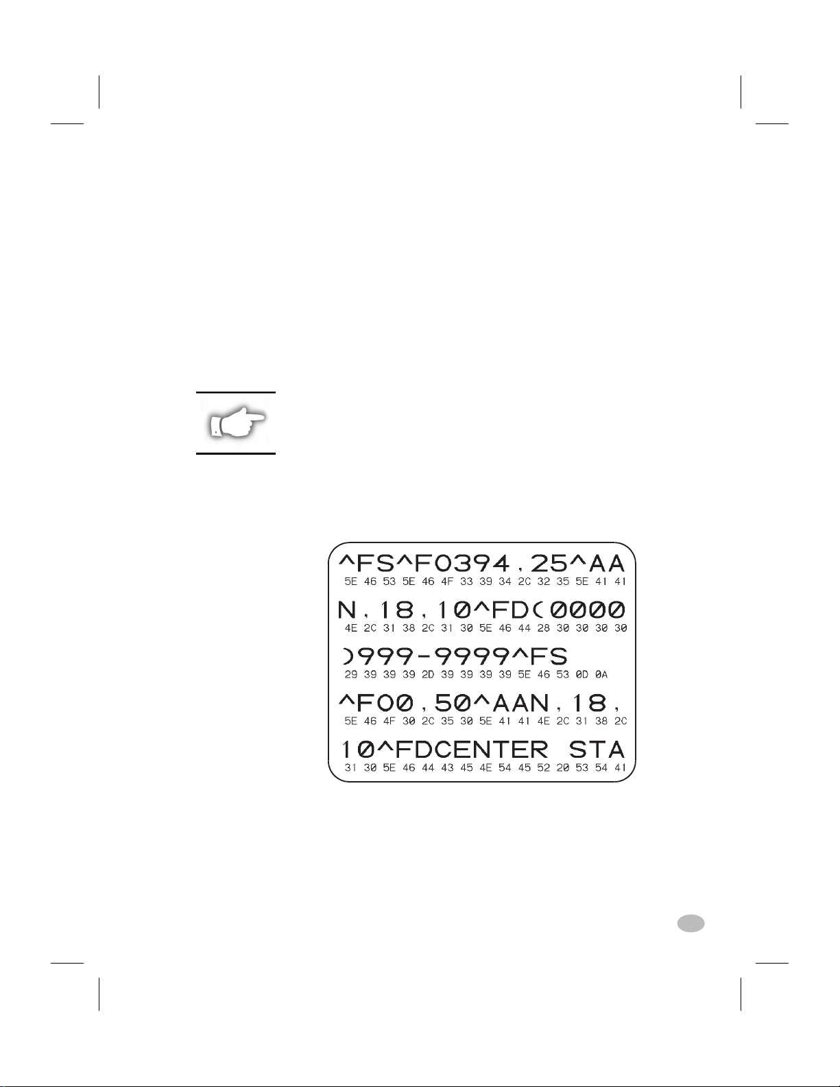
Communications Diagnostic Self-test
The Communications Diagnostic Mode is a troubleshooting tool for
checking the interconnection between the printer and the host computer.When “Diagnostics” is selected, all data sent to the printer will be
printed as straight ASCII hex characters. The printer prints all received
characters including control codes like CR (Carriage Return).
To enter the Communications Diagnostics mode, open the front panel
door and press and hold the
+ key while turning the printer power ON.
Release the key anytime after the first front panel LED turns OFF.
Send a label format from the host computer to the printer and observe
the printout on the label stock. Figure 23 provides an example of the
Diagnostic Mode printout.
NOTES: An FE indicates a framing error.
An OE indicates an overrun error.
An PE indicates a parity error.
An NE indicates noise.
If errors are indicated, check that your
communication parameters are correct.
Figure 23. Communications Diagnostics Self-test
H:...uspiran2.vp
Thu Jun 18 16:02:08 1998
Z Series™ User’s Guide 45
53
Page 54

Color profile: Disabled
Composite Default screen
Media and Ribbon Sensor Profile
The Media and Ribbon Sensor Profile may be used to troubleshoot registration problems that may be caused when the Media Sensor experiences difficulty in determining web location between labels.
To print a Media and Ribbon Sensor Profile, you must press and hold
the PAUSE key, FEED key, and CANCEL key while turning the
printer power ON. Release all three keys anytime after the first front
panel LED turns OFF. Figure 24 provides an example of the Media and
Ribbon Sensor Profile sample printout.
Figure 24. Media & Ribbon Sensor Profile
Resetting Factory Defaults
From time to time, it may be necessary to return the printer configuration to a "known" state. A set of Factory Defaults can be loaded into
the printer as a starting point from which one can then reconfigure the
printer for the application desired.
To reset Factory Defaults, press and hold both the PAUSE and FEED
keys while turning the printer power ON. Release both keys anytime
after the first front panel LED turns OFF. Once the Power-On Self Test
is completed, open the printer's front panel door and press the Print
Darkness Key two times to save the Factory Defaults parameters in
EEPROM memory. To signify that the parameters have been saved, all
three Control LEDs will flash on then off.
(An alternate method of setting Factory Defaults is by sending the ZPL
commands “^JUF^JUS” to the printer.) In addition, for printers with
the deluxe front panel, factory default settings may be saved through
the LCD configuration.
As of Firmware Release V22.8.4, this process no longer initializes the
optional on-board flash menory device nor the optional PCMCIA Card.
46 Z Series™ User’s Guide
H:...uspiran2.vp
Thu Jun 18 16:02:08 1998
54
Page 55

Color profile: Disabled
Composite Default screen
Initializing the Flash Memory and
PCMCIA Card
As of Firmware release V22.8.4, a new procedure is used to initialize
the optional on-board Flash Menory device and the optional PCMCIA
Card.
Prior to uploading new contents into the Flash Memory and/or the
PCMCIA Card, it is first necessary to initialize these devices. This procedure is performed by pressing and holding all three left hand control
keys inside the printer's front panel door while turning the printer
power ON. The keys may be released anytime after the first front panel
LED turns OFF. The Front Panel DATA LED will remain on until the
initialization process is finished.
NOTE: Initialization will erase the current contents of both devices.
Be sure to enable the Write Protect feature of the PCMCIA Card if you do
not want to initialize this device.
Automatically Executed Format
Once the Power On Self Test is completed and any self test labels are
printed, a check is made of the optional PCMCIA Memory Card and
then the optional Flash Memory for the presence of a stored format
named AUTOEXEC.ZPL. If an AUTOEXEC.ZPL format is encountered, it is automatically recalled and the preformatted labels are
printed.
If no AUTOEXEC.ZPL format is found, the printer enters the normal
operating mode and waits for operator input from the front panel or label format data to be received from the host computer.
H:...uspiran2.vp
Thu Jun 18 16:02:08 1998
Z Series™ User’s Guide 47
55
Page 56

Color profile: Disabled
Composite Default screen
Print Error Conditions
There are several error conditions that effect printing. Some actually
stop the printing process completely, while others are only reported to
the operator or host system. A printhead open error condition stops any
media movement, while the printhead under temperature error has no
effect on media movement. Some error conditions must be corrected
before the printer will feed or print labels again.
Media Out, Ribbon Out, Head Open, or Cutter Error
A media out, ribbon out, or cutter error condition stops the printer immediately and turns the ERROR LED on solid. A head open condition
also stops the printer and the ERROR LED blinks. The label being
printed, when the condition occurs, is only partially printed. The
PAUSE LED is turned ON and the printer waits for the errors to be
cleared and the PAUSE key to be pressed. If all error conditions are
cleared when the PAUSE KEY is pressed, the PAUSE LED will turn
OFF. Media registration occurs through the auto-calibration function
(for non-continuous media) and then the printing process resumes.
Printing resumes by reprinting the label that was in process when the
condition occurred, unless the printer is configured to NOT reprint partial labels. All of the other features of the printer (e.g., communications, parsing, formatting, and cancel) function normally during the
error condition and while the printer is “recovering.”
The feature of reprinting a label after an error condition occurs can be
turned off by a ZPL command. The type of media (continuous or noncontinuous) being monitored by the printer is controlled by a setting on
the front panel (LCD or DIP switches).
Printhead Over Temperature
When the printhead becomes too hot, all printing stops and the
ERROR LED blinks slowly. The printer will wait until the printhead
has returned to an acceptable temperature prior to restarting. All of the
other features of the printer function normally while the head is overtemperature, including feeding and calibrating without printing a label.
Printhead Under Temperature
A similar condition occurs when the printhead is cooler than desired.
The printer does NOT stop but the ERROR LED blinks slowly to indicate the error condition. All other printer features continue to work normally. This includes printing, which should heat the printhead to the
desired temperature.
48 Z Series™ User’s Guide
56
H:...uspiran2.vp
Thu Jun 18 16:02:08 1998
Page 57
Color profile: Disabled
Composite Default screen
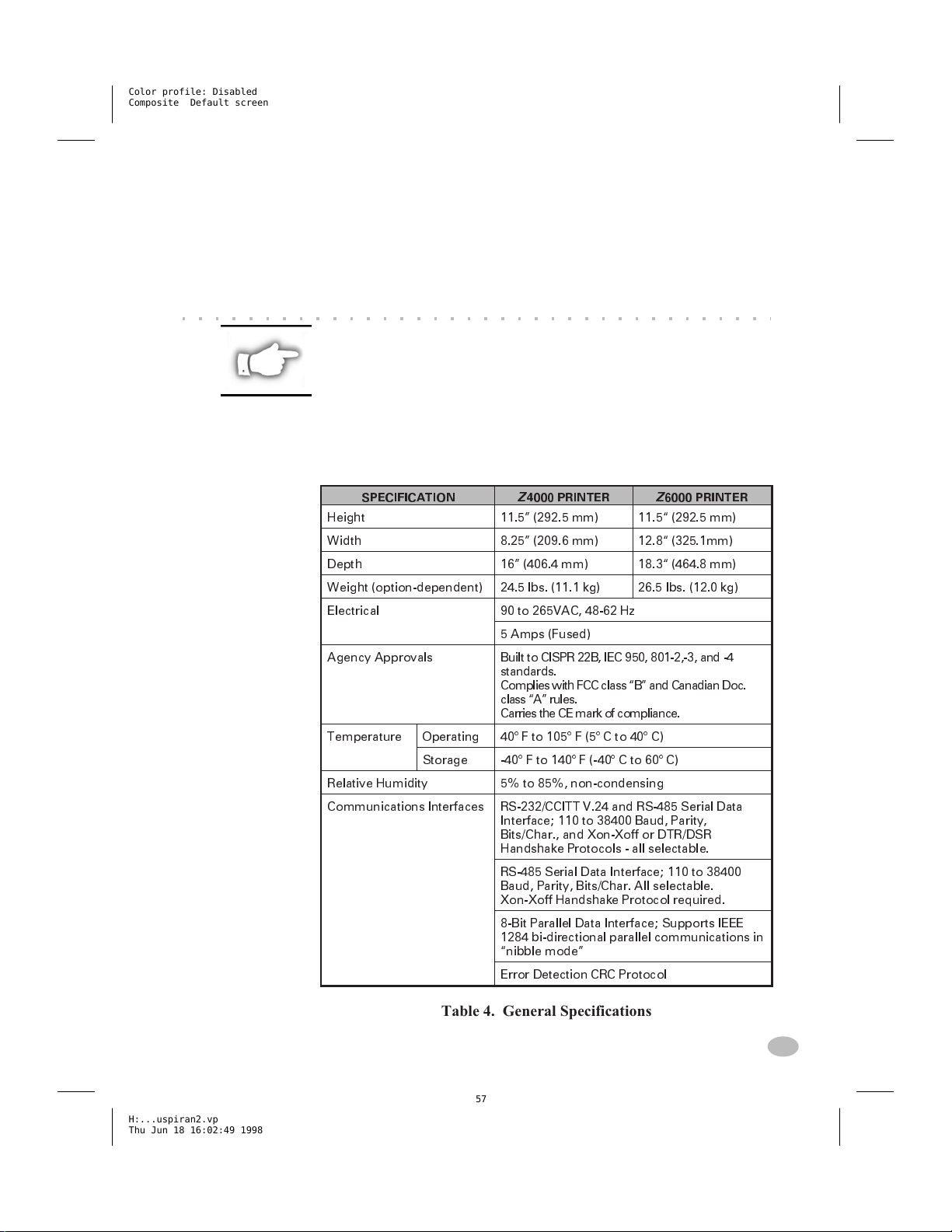
Printer Specifications
NOTE: Printer specifications are subject to change without notice. Your
printer may not have all of theoptions described in these specifications. If
you have questions as to the ability of the Z Series™ printer to meet the
needs of your application, contact either your Zebra Distributor or Zebra
Technologies Corporation.
General Specifications
SPECIFICATION
Height 11.5 (292.5 mm) 11.5 (292.5 mm)
Width 8.25 (209.6 mm) 12.8 (325.1mm)
Depth 16 (406.4 mm) 18.3 (464.8 mm)
Weight (option-dependent) 24.5 lbs. (11.1 kg) 26.5 lbs. (12.0 kg)
Electrical 90 to 265VAC, 48-62 Hz
Agency Approvals Built to CISPR 22B, IEC 950, 801-2,-3, and -4
Temperature Operating 40° F to 105° F (5° C to 40° C)
Storage -40° F to 140° F (-40° C to 60° C)
Relative Humidity 5% to 85%, non-condensing
Communications Interfaces RS-232/CCITT V.24 and RS-485 Serial Data
Z
4000 PRINTER
5 Amps (Fused)
standards.
Complies with FCC class B and Canadian Doc.
class A rules.
Carries the CE mark of compliance.
Interface; 110 to 38400 Baud, Parity,
Bits/Char., and Xon-Xoff or DTR/DSR
Handshake Protocols - all selectable.
RS-485 Serial Data Interface; 110 to 38400
Baud, Parity, Bits/Char. All selectable.
Xon-Xoff Handshake Protocol required.
8-Bit Parallel Data Interface; Supports IEEE
1284 bi-directional parallel communications in
nibble mode
Error Detection CRC Protocol
Z
6000 PRINTER
H:...uspiran2.vp
Thu Jun 18 16:02:49 1998
Table 4. General Specifications
Z Series™ User’s Guide 49
57
Page 58

Color profile: Disabled
Composite Default screen
Printing Specifications
PRINTING SPECIFICATIONS
Print Resolution
Dot size 203 dpi
Maximum print width
Print length Minimum
Maximum
continuous
media
(* 39 Max
for non-
continuous
media)
Bar code modulus (X) dimension
Programmable constant printing speeds
Additional printing speeds for printers with
the 203 dots/inch (8 dots/mm) printheads.
Thin film printhead with Energy Control
300 dpi
Std memory
8 dot/mm
12 dot/mm
Opt memory
8 dot/mm
12 dot/mm
Z
4000
PRINTER
203 dpi (8 dots/mm)
or 300 dpi (11.8 dots/mm)
0.00492 (0.125 mm) square
0.0033 x 0.0039(0.84 mm x 0.99 mm)
4.1 (104 mm) 6.6 (168 mm)
1 dot row
37 (940 mm)
16 (406 mm)
*136 (3.5 m)
*61 (1549 mm)
5 mil to 50 mil
2/sec. ( 50.8 mm/sec.)
3/sec. ( 76.2 mm/sec.)
4/sec. (101.6 mm/sec.)
5/sec. (127.0 mm/sec.)
6/sec. (152.4 mm/sec.)
7/sec. (177.8 mm/sec.)
8/sec. (203.2 mm/sec.)
9/sec. (228.6 mm/sec.)
10/sec. (254.0 mm/sec.)
Z
6000
PRINTER
23 (584 mm)
10 (254 mm)
*84 (2.1 m)
38 (965 mm)
Table 5. Printing Specifications
Ribbon Specifications
RIBBON SPECIFICATION
Ribbon Width (
recommends using ribbon
at least as wide as the
media to protect the
printhead from wear.
Standard
Lengths
Ribbon core inside diameter
50 Z Series™ User’s Guide
H:...uspiran2.vp
Thu Jun 18 16:02:49 1998
Zebra
)
2:1 media to ribbon roll ratio
3:1 media to ribbon roll ratio
Table 6. Ribbon Specifications
58
Z
4000 PRINTERZ6000 PRINTER
Minimum .94 (23.9 mm) 1.57 (39.9 mm)
Maximum 4.3 (110 mm) 6.85 (174 mm)
984 (300 m)
1476 (450 m)
1.0 (25.4 mm)
Page 59

Color profile: Disabled
Composite Default screen
Media Specifications
MEDIA SPECIFICATION
Total media
width
Label length Maximum
Total thickness
(includes liner)
Core size
Maximum roll diameter
Inter-label gap Maximum
Ticket/tag notch size (Width x Length) 0.236 (6 mm) x 0.12 (3.0 mm)
Maximum
Minimum
Minimum Tear-Off
Maximum (
printhead pressure may
need adjustment
Minimum
Minimum [
preferred
Mode
Rewind
Mode
Peel-Off
Mode
Cutter
Mode
If above 0.01",
)
0.118 (3 mm)
]
Z
4000
PRINTER
4.5 (115 mm) 7.0(178 mm)
1.0 (25.4 mm) 2.0(50.8 mm)
See Printing Specifications
0.5 (12.7 mm).
0.5 (12.7 mm)
1.0 ( 25.4 mm)
1.0 (25.4 mm)
0.010 (0.25 mm)
0.0023 (0.058 mm)
3.0 (76.2 mm)
8.0 (203 mm)
0.157 (4 mm)
0.079 (2 mm)
Z
6000
PRINTER
H:...uspiran2.vp
Thu Jun 18 16:02:49 1998
Pressure sensitive media: release liner must be free of preprint (with
the exception of black mark registration) and is recommended to not
exceed .0035" (.089 mm) thickness (60 lb stock).
Table 7. Media Specifications
Z Series™ User’s Guide 51
59
Page 60

Color profile: Disabled
Composite Default screen
Zebra Programming Language (ZPL II®)
Downloadable graphics (with
n
data compression)
Programmable quantity with print
n
pause
Bit image data transfer and print-
n
ing, mixed text/graphics
Format inversion
n
Mirror image printing
n
Four-position field rotation
n
(0°, 90°, 180°, 270°)
Slew command
n
Serialized fields
n
Bar Codes
n
Code 11
n
Code 39 (supports ratios
of 2:1 to 3:1)
n
Code 49 (2-dimensional
bar code)
n
Code 93
n
Code 128 (supports serialization in all subsets and
UCC case codes)
n
Codabar (supports ratios
of 2:1 to 3:1)
n
Codablock
n
Interleaved 2 of 5 (supports
ratios of 2:1 to 3:1, modulus
10 check digit)
n
Industrial 2 of 5
n
Standard 2 of 5
Communicates in printable
n
ASCII characters
Controlled via mainframe, mini,
n
PC, Portable Data Terminal
In-Spec OCR-A and OCR-B
n
UPC/EAN [nominal 100% mag-
n
nification (6 dot/mm printheads
only)]
n
LOGMARS
n
Plessey
n
EAN-8, EAN-13,
EAN EXTENSIONS
n
UPC-A, UPC-E,
UPC EXTENSIONS
n
MSI
n
PDF-417 (2-dimensional
bar code)
n
POSTNET
n
MaxiCode
n
Datamatrix
n
QR Code (added with
Firmware Release V22.8.3
n
Check digit calculation
where applicable
52 Z Series™ User’s Guide
60
H:...uspiran2.vp
Thu Jun 18 16:02:50 1998
Page 61

Color profile: Disabled
Composite Default screen
Standard Printer Fonts
For more information on fonts, refer to the ZPL II Programming Guide.
203 DOTS/INCH (8 DOTS/MM) PRINTHEAD
Fonts
A 9 x 5 U-L-D 0.044 x 0.030 33.3
B 11 x 7 U 0.054 x 0.044 22.7
C, D 18 x 10 U-L-D 0.089 x 0.059 16.9
E 28 x 15 OCR-B 0.138 x 0.098 10.2
F 26 x 13 U-L-D 0.128 x 0.079 12.7
G 60 x 40 U-L-D 0.295 x 0.236 4.2
H 21 x 13 OCR-A 0.103 x 0.093 10.8
GS 24 x 24 SYMBOL 0.118 x 0.118 8.5
Ø 15 x 12 SCALEABLE (SMOOTH) FONT
* Type: U - Upper Case, L - Lower Case, D - Descenders
Dot Matrix
(h x w)
(Defaults)
Type*
Minimum
Character
Size (h x w)
Max
Char
/In
300 DOTS/INCH (11.8 DOTS/MM) PRINTHEAD
Font
A 9 x 5 U-L-D 0.030 x 0.020 50.8
B 11 x 7 U 0.036 x 0.030 33.8
C, D 18 x 10 U-L-D 0.059 x 0.040 25.4
E 42 x 20 OCR-B 0.138 x 0.085 23.4
F 26 x 13 U-L-D 0.085 x 0.053 19.06
G 60 x 40 U-L-D 0.197 x 0.158 6.36
H 34 x 22 OCR-A 0.111 x 0.098 10.02
GS 24 x 24 SYMBOL 0.079 x 0.079 12.7
Ø Variable SCALABLE (SMOOTH) FONT
* Type: U - Upper Case, L - Lower Case, D - Descenders
n
Bit-mapped fonts A, B, D, E, F, G, H, and GS are expandable up to
Dot Matrix
(h x w)
(Defaults)
Type*
Minimum
Character
Size (h x w)
Max
Char
/In
10 times, height- and width-independent. However, fonts E and H
(OCR-B and OCR-A) are not considered in-spec when expanded.
n
The Scaleable Smooth Font (CG Triumvirate™ Bold Condensed) is
expandable on a dot-by-dot basis, height- and width-independent,
while maintaining smooth edges, to a maximum of 1500 x 1500
dots.
n
IBM Code Page 850 International characters available in fonts A, B,
D, E, F, G and Ø through software control.
H:...uspiran2.vp
Thu Jun 18 16:02:50 1998
Z Series™ User’s Guide 53
61
Page 62

Color profile: Disabled
Composite Default screen
Standard Printer Font Examples
Default Printer Fonts - 300 dots/inch (12 dots/mm)
Default Printer Fonts - 203 dots/inch (8 dots/mm)
54 Z Series™ User’s Guide
62
H:...uspiran2.vp
Thu Jun 18 16:02:51 1998
Page 63

Color profile: Disabled
Composite Default screen
Optional Printer Fonts
There are many optional character fonts that can be purchased for your
Z Series™ printer, in addition to those which are standard in the unit.
From time to time, additions may be made to the list of available fonts.
Contact your sales representative for further information.
Once installed, the optional fonts can be used in addition to the standard fonts available in the printer. Refer to your ZPL II Programming
Guide or, if using another software package to drive your printer, to the
instructions accompanying that package.
H:...uspiran2.vp
Thu Jun 18 16:02:51 1998
Z Series™ User’s Guide 55
63
Page 64

Color profile: Disabled
Composite Default screen
56 Z Series™ User’s Guide
64
H:...uspiran2.vp
Thu Jun 18 16:02:52 1998
Page 65
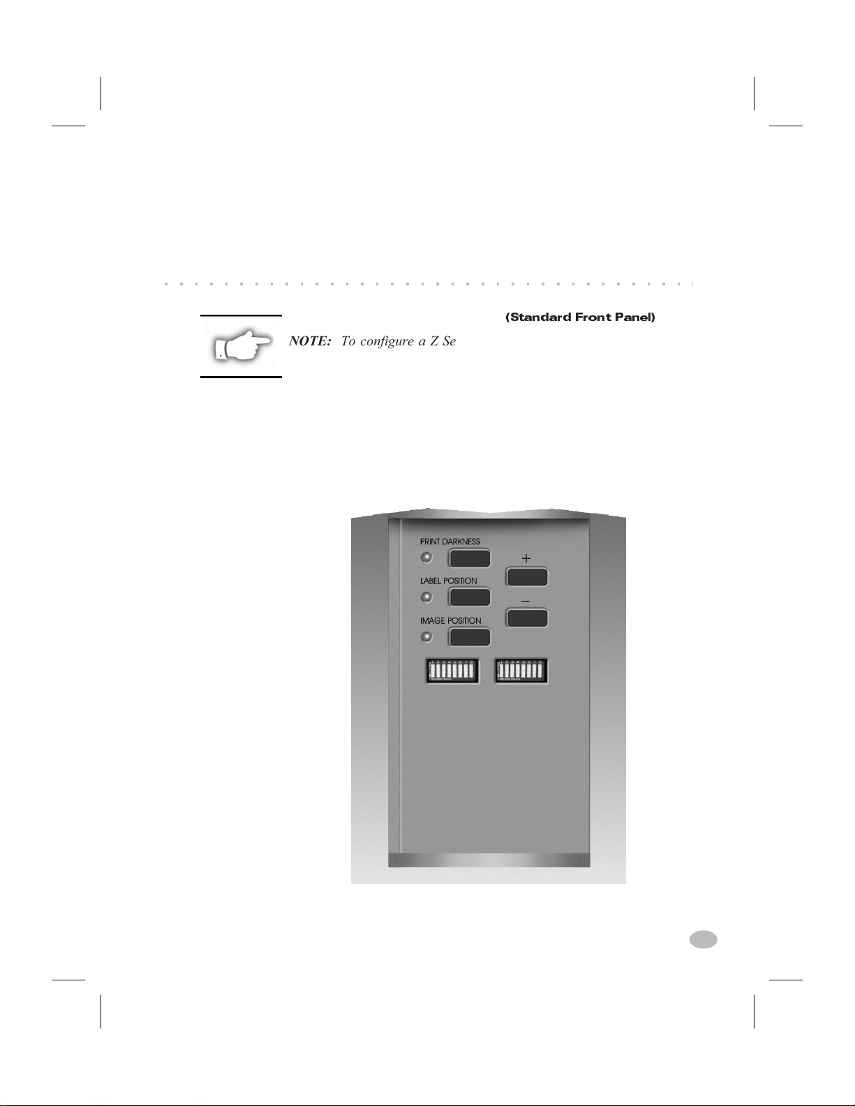
Color profile: Disabled
Composite Default screen
Appendix A
Printer Configuration
(Standard Front Panel)
NOTE: To configure a Z Series™ printer having the optional deluxe
front panel, refer to the information found later in this section.
Serial Communications Parameters
Refer to Figure 25. When using serial communication, the Bank One
(left) switches inside the front panel door must match the communication parameters of the printer with those of your host computer. When
shipped from the factory, all switches are in the ON position. This presets the printer to match the typical PC environment - 9600 Baud,
8 Data Bits, No Parity, and Xon/Xoff Handshaking.
H:...uspiran2.vp
Thu Jun 18 16:03:33 1998
Figure 25. Standard Front Panel
Z Series™ User’s Guide 57
65
Page 66

Color profile: Disabled
Composite Default screen
Refer to Table 8 if the settings need to be changed to match those of
your host computer. If you do not know the settings of your host computer, refer to the instruction manual provided with the computer.
The serial port supports an Error Detection Protocol which sends and
receives data in packets. This “Zebra” protocol must be compatible
with your host computer and your application software. Received
packets are checked for accuracy. If received correctly, the data in the
packet is processed and an “acknowledge” packet is sent back to the
host. If an error is found in the received packet, either a “negative
acknowledge” packet or no response will be sent to the host. DO NOT
enable Error Detection unless your host is programmed to use it. For
additional information, refer to the ZPL II Programming Guide.
If the Bank One switches are in the proper position to match the communication configuration of the host computer, and the printer is not
receiving data, see Appendix B to make sure you are using the correct
interface cable.
OFF
DIP Switch
Positions
BAUD RATE SWITCH 1 SWITCH 2 SWITCH 3
9600 ON ON ON
19200 OFF ON ON
ON
28800 ON OFF ON
38400 OFF OFF ON
600 ON ON OFF
1200 OFF ON OFF
2400 ON OFF OFF
4800 OFF OFF OFF
DATA BITS SWITCH 4
8 Data Bits ON
7 Data Bits OFF
HANDSHAKE SWITCH 5
Xon/Xoff ON
DTR/DSR OFF
PARITY SWITCH 6 SWITCH 7
Parity Disabled ON ON
Even OFF ON
Odd ON OFF
Parity Disabled OFF OFF
ERROR DETECTION SWITCH 8
Off ON
On OFF
NOTE: The printer requires one (1)
stop bit minimum on received data
and automatically supplies two (2)
stop bits for transmitted data.
NOTE: Zebra Protocol is the default
Error Detection Protocol enabled
when On - Switch 8 OFF is selected.
Table 8. Bank 1 Switch Settings
58 Z Series™ User’s Guide
66
H:...uspiran2.vp
Thu Jun 18 16:03:33 1998
Page 67

Color profile: Disabled
Composite Default screen
DIP Switch
Positions
Operating Modes
Use the Bank Two (right) switches to select printer operating modes.
When shipped from the factory, all switches are in the ON position.
This presets the printer to match the most commonly used modes of
operation - Tear-Off Mode, Non-continuous Media, Thermal Transfer
Operation, and RS-232 Serial Communications.
If your printer is equipped with an option such as rewind, peel-off, or
cutter, or if your application requires a different operating mode such as
direct thermal, or continuous media, refer to Table 9 for the appropriate
Bank Two switch settings.
DIP SWITCH/ZPL CONTROL SWITCH 1
Dip Switches 2 - 6 Override ZPL ON
ZPL Overrides Dip Switches 2 - 6 OFF
ON
OFF
PRINT MODE SWITCH 2 SWITCH 3
Tear-Off ON ON
Peel-Off OFF ON
Cutter ON OFF
Rewind OFF OFF
MEDIA TYPE SWITCH 4 SWITCH 5
Non-Continuous
Web Sensing
Non-Continuous
Mark Sensing
Continuous OFF OFF
PRINT METHOD SWITCH 6
Thermal Transfer ON
Direct Thermal OFF
SERIAL COM MODE SWITCH 7 SWITCH 8
RS-232 ON ON
RS-422/RS485
Single-Drop
RS-485 Multi-Drop OFF OFF
ON ON
ON OFF
OFF ON
H:...uspiran2.vp
Thu Jun 18 16:03:34 1998
Table 9. Bank 2 Switch Settings
NOTE: The printer automatically senses if a parallel communications
cable is connected from your host computer. The Bank One switches and
Bank Two switches 7 and 8 have no effect on parallel communications.
To see a printout of the printer configuration, perform the CANCEL
Key Self Test. See the “Troubleshooting” section for more details.
Z Series™ User’s Guide 59
67
Page 68

Color profile: Disabled
Composite Default screen
Standard Front Panel Control Keys
If you need to adjust the print darkness, label position or the image position on the label, use the following control keys located inside the
front panel door to configure these parameters.
Print Darkness Key
Press this key (LED turns ON) to change the print darkness setting by
pressing the PLUS (+) or MINUS (-) keys. Each press of the + or - key
changes the setting by one step. Press the Print Darkness key a second
time to save the new setting. The darkness setting limits are from zero
(0) to 30.
Label Position Key
Press this key (LED turns ON) to change the label tear off/cut off
position setting by pressing the (+) or (-) keys. Each press of the + or key changes the setting by four dot rows. Press the Label Position key
a second time to save the new setting. From the default value, the setting may be changed +120 or -120 dot rows.
Image Position Key
Press this key (LED turns ON) to change the image position setting by
pressing the (+) or (-) keys. Each press of the + or - key changes the
setting by four dot rows. Press the Image Position key a second time to
save the new setting. From the default value, the setting may be
changed +120 or -120 dot rows.
Plus Key(+)
When setting print darkness, each press of this key increases the darkness setting by 1.
When setting the label position, each press of this key moves the label
tear off/cut off position four dot rows away from the end of the label
just printed.
When setting the image position, each press of this key moves the image
four dot rows away from the leading edge of the label being printed.
Minus Key(-)
Pressing this key has the opposite effect on the settings from the PLUS
key.
60 Z Series™ User’s Guide
68
H:...uspiran2.vp
Thu Jun 18 16:03:34 1998
Page 69

Color profile: Disabled
Composite Default screen
Printer Configuration
(Deluxe Front Panel)
NOTE: To configure a Z Series™ printer having the standard front
panel, refer to the information found earlier in this section.
Deluxe Front Panel Control Keys
Refer to Figure 26. Opening the door on the front panel provides access
to the control keys used for configuring the printer’s operating features.
The Liquid Crystal Display (LCD) shows the menus as you proceed
through the configuration process.
H:...uspiran2.vp
Thu Jun 18 16:03:35 1998
Figure 26. Deluxe Front Panel
The configuration sequence is a series of menus and prompts with programmable parameters for each menu listing.
START/SAVE Key
Press this key to enter the configuration mode. Once in the configuration mode, the first major menu selection (General Setup) is displayed.
Z Series™ User’s Guide 61
69
Page 70

Color profile: Disabled
Composite Default screen
NEXT MENU Key
Press this key to increment through the major menu headings, showing
the top level of each configuration section. When the end of the menu
listing is reached, the list repeats automatically.
NEXT ITEM Key
Once the appropriate major menu is visible on the LCD display, the
NEXT ITEM key can be used to sequence through the configuration
prompts for that menu. When the end of the item listing is reached, the
list repeats automatically.
When the appropriate item is displayed, the PLUS (+) and MINUS (-)
keys can be used to select the setting for that item.
PLUS Key(+)
Press this key to increment the value of the item selected on the LCD.
MINUS Key(-)
Press this key to decrement the value of the item selected on the LCD.
NOTE: When entering specific numeric values, use the MINUS key to
select the digit position and the PLUS key to select the value for that
position.
Front Panel Programming
Table 10 provides the printer configuration parameters in the sequence
in which they appear on the front panel LCD display. The DEFAULT
value as well as the available choices for each parameter are given.
Once in the configuration mode, pressing the NEXT MENU key at any
time will exit the current major menu feature list and move to the next
major menu heading. An asterisk “*” appears in the upper left corner of
the LCD if the value selected is different from the one currently saved.
NOTE: Whenever a password is requested during the configuration
process, the default value of “1234” may be entered . This password may
be changed via a programming command sent to the printer from the host
computer.
62 Z Series™ User’s Guide
70
H:...uspiran2.vp
Thu Jun 18 16:03:36 1998
Page 71

Color profile: Disabled
Composite Default screen
GENERAL SETUP MENU
PARAMETER SELECTIONS
LANGUAGE Use the PLUS key or MINUS key to sequence
through the LCD selections until the appropriate
language is displayed.
Default: English
Choices: English, Spanish, French, German, Italian,
Norwegian, Portuguese, Swedish, Danish,
Spanish2, Dutch, Finnish or Custom.
DARKNESS Set the darkness to the lowest setting possible for
consistent high quality printing.
To observe the effects of the newly entered value,
go to the Print Listings parameter and print a setup
label.
Default: 10 Range: 0 to 30
TEAR OFF This value sets the media rest position over the
Tear/Peel Bar after printing or the cut-off point for
cutter applications.
Default: 00 Range: -120 to +120
PRINT MODE Select a print mode that your hardware
configuration supports, since some selections
are for optional printer features.
Default: Tear Off Choices: Tear Off, Rewind,
Cutter, Peel Off
LABEL TOP This value sets the print position vertically on the
label. A more positive value moves the label top
position farther down the label. A negative value
moves the label top position up the label.
Default: 00 Range: -120 to +120
LCD ADJUST If the LCD is difficult to read, use the PLUS key or
MINUS key to adjust the brightness of your display.
H:...uspiran2.vp
Thu Jun 18 16:03:36 1998
Default: 10 Range: 00 to 19
Continued on the following page.
Table 10. Deluxe Front Panel Configuration
Z Series™ User’s Guide 63
71
Page 72

Color profile: Disabled
Composite Default screen
COMMUNICATIONS
PARAMETER SELECTIONS
BAUD
(password
Select the value that matches the one used by the
host.
required)
Default: 9600
DATA BITS
(password
required)
PARITY
(password
required)
HOST HANDSHAKE
(password
required)
PROTOCOL
(password
required)
SERIAL COMM
(password
required)
Choices: 600, 1200, 2400, 4800, 9600,
19200, 28800, or 38400
Select the value that matches the one used by the
host. (Mustbe set to 8 databits to use Code Page 850.)
Default: 8 bits/character
Choices: 7 bits/character or 8 bits/character
NOTE:
The printer requires one (1) stop bit
minimum on received data and
automatically supplies two (2) stop bits
for transmitted data.
Select the value that matches the one used by the
host.
Default: None Choices: Even, Odd, None
Select the value that matches the one used by the
host.
Default: XON/XOFF
Choices: XON/XOFF or DTR/DSR
Details on protocol can be found in the
Programming Guide
, available from Zebra
ZPL II
Technologies Corporation.
Default: None Choices: None, Ack-Nak, Zebra
NOTE:
Zebra Protocol is the same as ACK/NAK
except that with Zebra the response
messages are sequenced. If Ack-Nak or
Zebra is selected, then DTR/DSR Host
Handshake must be selected.
Select the choice that matches the one used by the
host.
Default: RS232 Choices: RS232, RS422/RS485,
or RS485 Multidrop
Continued on the following page.
64 Z Series™ User’s Guide
72
H:...uspiran2.vp
Thu Jun 18 16:03:36 1998
Page 73

Color profile: Disabled
Composite Default screen
COMMUNICATIONS
PARAMETER SELECTIONS
NETWORK ID
(password
required)
The network ID is used to assign a unique number to
a printer used in a network. This gives the host the
means to address a specific printer.
Default: 000 Choices: 000 to 999
NOTE:
If the printer is used in a network, you
select a network ID number
COMMUNICATIONS
(password
required)
The communications diagnostics mode is a trouble-
shooting tool for checking the interconnection
between the printer and the host. When Diagnostics
is selected, all data sent from the host to the printer
will be printed as straight ASCII hex characters. All
received characters, including control codes like CR
(Carriage Return), are printed.
Default: Normal Mode
Choices: Normal Mode or Diagnostics Mode
must
NOTES:
An FE indicates a framing error.
An OE indicates an overrun error.
An PE indicates a parity error.
An NE indicates noise.
If errors are indicated, check that your
communication parameters are correct.
PRINT LISTINGS
PARAMETER SELECTIONS
LIST FONTS Press + to print a list of all standard and optional
fonts currently available in the printer.
LIST BARCODES Press + to print a list of all the barcodes currently
available in the printer.
LIST IMAGES Press + to print a list of all the images currently
available in the printer.
LIST FORMATS Press + to print a list of all the formats currently
available in the printer.
LIST SETUP Press + to print the printers current configuration.
LIST ALL Press + to print all of the previously indicated lists.
Continued on the following page.
H:...uspiran2.vp
Thu Jun 18 16:03:36 1998
Z Series™ User’s Guide 65
73
Page 74

Color profile: Disabled
Composite Default screen
MEDIA SETUP
PARAMETER SELECTIONS
MEDIA TYPE Select the type of media you are using.
Default: Non-Continuous
Choices: Continuous or non-continuous
NOTE:
Selecting continuous media requires that
you include a label length instruction in
your label format (^LLxxxx - if you are
using ZPL or ZPL II).
SENSOR TYPE Select the type of media sensing you will use:
- Web if a gap, space, notch, or hole is used to
indicate the separations between labels.
- Mark if a black mark printed on the back of the
media is used to indicate the separations between
labels. (If your media does not have black marks
on the back, leave the printer at the default - Web.)
Default: Web Choices: Web or Mark
PRINT METHOD Select the method of printing you wish to use.
- Direct thermal requires the use of heat sensitive
label stock (no ribbon needed).
- Thermal transfer uses many types of label stock
along with an inked ribbon.
Default: Thermal transfer
Choices: Thermal Transfer or Direct Thermal
NOTE:
Selecting direct thermal when using thermal
transfer media and ribbon creates a warning
condition, but printing will continue.
PRINT WIDTH Select a print width that is the closest to and at least
as wide as your media. Setting the width too
narrow may result in unprinted portions of your
label format. Setting the width too wide wastes
formatting memory and may cause printing off the
right side of the label.
Default: 104 mm (Z4000)
168 mm (Z6000)
Choices: Up to 104 mm (Z4000)
Up to 168 mm (Z6000)
NOTE:
Move the curser under mm using the
MINUS key, use the PLUS key to change the
reading from mm to inches or dots.
Continued on the following page.
66 Z Series™ User’s Guide
H:...uspiran2.vp
Thu Jun 18 16:03:36 1998
74
Page 75

Color profile: Disabled
Composite Default screen
CALIBRATION
PARAMETER SELECTIONS
MEDIA POWER UP
(password
This parameter establishes the action of the media
when the printer is turned ON.
required)
Default: Calibration
Choices: Calibration - recalibrates media and ribbon
sensors by feeding labels
Feed - feeds the label to the first web
Length - determines the length of the label
by feeding labels
No Motion - media does not move
HEAD CLOSE
(password
required)
This parameter establishes the action of the media
after the printhead has been opened and then
closed.
Default: Calibration
Choices: Calibration - recalibrates media and ribbon
sensors by feeding labels
Feed - feeds the label to the first web
Length - determines the length of the label
by feeding labels
No Motion - media does not move
MANUAL CALIBRATE If the auto-calibration feature has been disabled by a
ZPL command from the host or the HEAD CLOSE
parameter is not Calibrate, you may use this
feature to calibrate the media and ribbon sensors.
Press + to enable the Calibration process.
NOTE:
If the printer is configured for continuous
media, no media movement will occur during
the Calibration process.
SENSOR PROFILE The Media and Ribbon Sensor Profile provides a
graphical representation of the Media and Ribbon
Sensor settings as an aid to the Service Technician if
problems with inter-label gap sensing occur.
H:...uspiran2.vp
Thu Jun 18 16:03:36 1998
Press + to enable the Sensor Profile printout.
WEB S.
MEDIA S.
RIBBON S.
MEDIA LED
RIBBON LED
THESE SETTINGS SHOULD ONLY BE CHANGED
BY AN AUTHORIZED SERVICE TECHNICIAN.
(A password is required)
Refer to the
Z Series Maintenance Manual
for
additional information about these settings.
Continued on the following page.
Z Series™ User’s Guide 67
75
Page 76

Color profile: Disabled
Composite Default screen
ZPL CONTROL
PARAMETER SELECTIONS
CONTROL PREFIX
(password
required)
The printer looks for this 2-digit hex value to
indicate the start of a ZPL/ZPL II Control instruction.
Refer to the
ZPL II Programming Guide
information.
Default: 7E (tilde - displayed as a black square)
for more
FORMAT PREFIX
(password
required)
DELIMITER CHAR
(password
required)
ZPL MODE
(password
required)
Choices: most hex values between 00 and FF
(exclude the values indicated on the ASCII
Code Chart in Appendix C)
The printer looks for this 2-digit hex value to
indicate the start of a ZPL/ZPL II Format instruction.
Refer to the
ZPL II Programming Guide
for more
information.
Default: 5E (caret)
Choices: most hex values between 00 and FF
(exclude the values indicated on the ASCII
Code Chart in Appendix C)
The printer looks for this 2-digit hex value used as a
parameter place marker in ZPL/ZPL II instruction.
Refer to the
ZPL II Programming Guide
for more
information.
Default: 2C (comma)
Choices: most hex values between 00 and FF
(exclude the values indicated on the ASCII
Code Chart in Appendix C)
The printer will remain in the selected mode until it
is changed by this parameter or by sending a
ZPL/ZPL II command. The printer accepts label
formats written in either ZPL or ZPL II. This
eliminates the need to rewrite any ZPL formats you
already have. Refer to the
Guide
for more information.
ZPL II Programming
Default: ZPL II
Choices: ZPL II or ZPL
Continued on the following page.
68 Z Series™ User’s Guide
76
H:...uspiran2.vp
Thu Jun 18 16:03:37 1998
Page 77

Color profile: Disabled
Composite Default screen
ADVANCED SETUP
PARAMETER SELECTIONS
BACKFEED
(password
required)
In the Cutter mode, this parameter establishes
when and how much label backfeed occurs after a
label is cut. It has no effect in the Tear-Off, Peel, or
Rewind modes. This parameter can be superseded
by the ~JS instruction when received as part of a
label format. (Refer to the
Guide
.)
ZPL Programming
Default: Default (default is defined as 90%)
Choices: Default, After, Off, Before, 10%, 20%,
30%, 40%, 50%, 60%, 70%, 80%
NOTE:
The difference between the value entered and
100% establishes how much backfeed occurs
before the next label is printed. For example, a
value of 40 means that 40% of the backfeed
takes place after the label is cut. The remaining
60% takes place before the next label prints. A
value of before means that all backfeed will
take place before the next label is printed.
LEFT POSITION This parameter establishes how far from the left
edge of a label the format will begin to print by
adjusting the horizontal positioning on the label.
Positive numbers adjust the printing to the left by
the number of dots selected. Negative numbers
shift printing to the right.
H:...uspiran2.vp
Thu Jun 18 16:03:37 1998
Default: 000
Choices: -9999 to +9999
NOTE:
For a negative value, enter the value before
entering the minus sign.
INITIALIZE CARD
(password
This parameter allows you to initialize (erase) the
PCMCIA Card installed in the optional PCMCIA Port.
required)
Press+to initialize. Then, if not sure, press-for
NO, or if you are sure, press+for YES.
INIT FLASH MEM
(password
required)
This parameter allows you to initialize (erase) the
optional non-volatile memory installed in the
printer.
Press+to initialize. Then, if not sure, press-for
NO, or if you are sure, press+for YES.
Continued on the following page.
Z Series™ User’s Guide 69
77
Page 78

Color profile: Disabled
Composite Default screen
Exiting the Configuration mode
When you are finished changing or reviewing the necessary parameters, press the START/SAVE key. Use the NEXT ITEM key to select
one of the “SAVE” choices shown below; then press the START/
SAVE key again to end the configuration process.
n
PERMANENT - new settings overwrite previous values in
configuration memory.
n
TEMPORARY - printer operates with new settings until power
is turned off; when power is turned back on, the printer
reverts back to the PERMANENT values.
n
CANCEL - printer makes no changes and returns to the current
settings.
n
LOAD DEFAULTS - all values return to the factory settings.
n
LOAD LAST SAVE - printer operates with last set of values
saved (either permanent or temporary).
70 Z Series™ User’s Guide
78
H:...uspiran2.vp
Thu Jun 18 16:03:37 1998
Page 79

Appendix B
Communication Interfaces
Data cables must be fully shielded and fitted with metal or metalized
connector shells to prevent radiation and reception of electrical noise.
To minimize electrical noise pickup in the cable:
n
Keep data cables as short as possible.
n
Do not bundle the data cables tightly with power cords.
n
Do not tie the data cables to power line conduits.
Serial Data Communications
Table 11 illustrates the pin connections on the DB-25 connector at the
rear of the printer.
PIN NO. DESCRIPTION
Chassis Ground
1
TXD (Transmit Data) output from the printer
2
RXD (Receive Data) input to the printer
3
RTS (Request To Send) output from the printer
4
Not Used
5
DSR (Data Set Ready) input to the printer
6
RS-232 Signal Ground
7
Not Used
8
+5V @ 1A source
9
Not Used
10
RS-485 Signal Ground
11
Not Used
12
RS-485 Input B (-)
13
RS-485 Output B (-)
14
Not Used
15
RS-485 Input A (+)
16
17-18
21-25
Not Used
RS-485 Output A (+)
19
DTR (Data Terminal Ready) output from the printer
20
Not Used
Table 11. Rear Panel Serial Data Port Pinout
Z Series™ User’s Guide 71
Page 80

RS-232 Interface
RS-232 Interface
The Z Series printer is configured as Data Terminal Equipment
The Z Series printer is configured as Data Terminal Equipment
(DTE). The serial data cable used to connect the printer to the host
(DTE). The serial data cable used to connect the printer to the host
computer will be one of two styles:
computer will be one of two styles:
n
n
9-pin to 25-pin cable - (NULL Modem Cable) must have a 9-pin
9-pin to 25-pin cable - (NULL Modem Cable) must have a 9-pin
“D” Type (DB9S) connector on the end that is plugged into the
“D” Type (DB9S) connector on the end that is plugged into the
serial port at the computer and a 25-pin “D” Type (DB25P)
serial port at the computer and a 25-pin “D” Type (DB25P)
connector on the other end that is plugged into the connector at the
connector on the other end that is plugged into the connector at the
rear of the printer. Figure 27 shows the required cable connections.
rear of the printer. Figure 27 shows the required cable connections.
DB-9S
Connector
to P.C.
DB-25P
Connector
to Printer
Figure 27. 9-Pin to 25-Pin Cable
n
n
25-pin to 25-pin cable - (NULL Modem Cable) must have a 25-pin
25-pin to 25-pin cable - (NULL Modem Cable) must have a 25-pin
“D” Type (DB25S) connector on the end that is plugged into the
“D” Type (DB25S) connector on the end that is plugged into the
serial port at the computer and a 25-pin “D” Type (DB25P)
serial port at the computer and a 25-pin “D” Type (DB25P)
connector on the other end that is plugged into the connector at the
connector on the other end that is plugged into the connector at the
rear of the printer. Figure 28 shows the required cable connections.
rear of the printer. Figure 28 shows the required cable connections.
DB-25S
Connector
to P.C.
1
2
3
6
7
8
20
CTS
DB-25P
Connector
to Printer
1
2
3
4
6
7
20
Figure 28. 25-Pin to 25-Pin Cable
72 Z Series™ User’s Guide
Page 81

Hardware Control Signal Descriptions
For all RS-232 input and output signals, the Z Series™ printer follows
both the Electronics Industries Association (EIA) RS-232 and the Consultative Committee for International Telegraph and Telephone
(CCITT) V.24 standard signal level specifications.
When DTR/DSR handshaking is selected, the Data Terminal Ready
(DTR) control signal output from the printer controls when the host
computer may send data. DTR ACTIVE (positive voltage), permits the
host to send data. When the printer places DTR in the INACTIVE
(negative voltage) state, the host must not send data.
NOTE: When Xon/Xoff handshaking is selected, data flow is controlled
by the ASCII Control Codes DC1 (XON) and DC3 (XOFF). The DTR
Control lead will have no effect.
Request To Send (RTS) is a control signal from the printer which is
connected to the Clear To Send (CTS) input at the host computer. RTS
is always ACTIVE (positive voltage) when the printer is ON.
CAUTION: The Z Series™ printers comply with FCC “Rules and
Regulations”, Part 15 for Class B Equipment, using fully shielded
six-foot data cables. Use of longer cables or unshielded cables may
increase radiated emissions above the Class B limits.
RS-485 Interface
Figure 29 illustrates the pin connections on the DB-25 connector at the
rear of the printer which are used for the RS-485 communication
protocol.
NOTE: Xon/Xoff handshaking must be used for RS-485 communications.
DB-25P
Connector
to Printer
Data Input A (–)
Data Output A (–)
Data Input B (+)
Data Output B (+)
Figure 29. RS-485 Cable
Z Series™ User’s Guide 73
Page 82
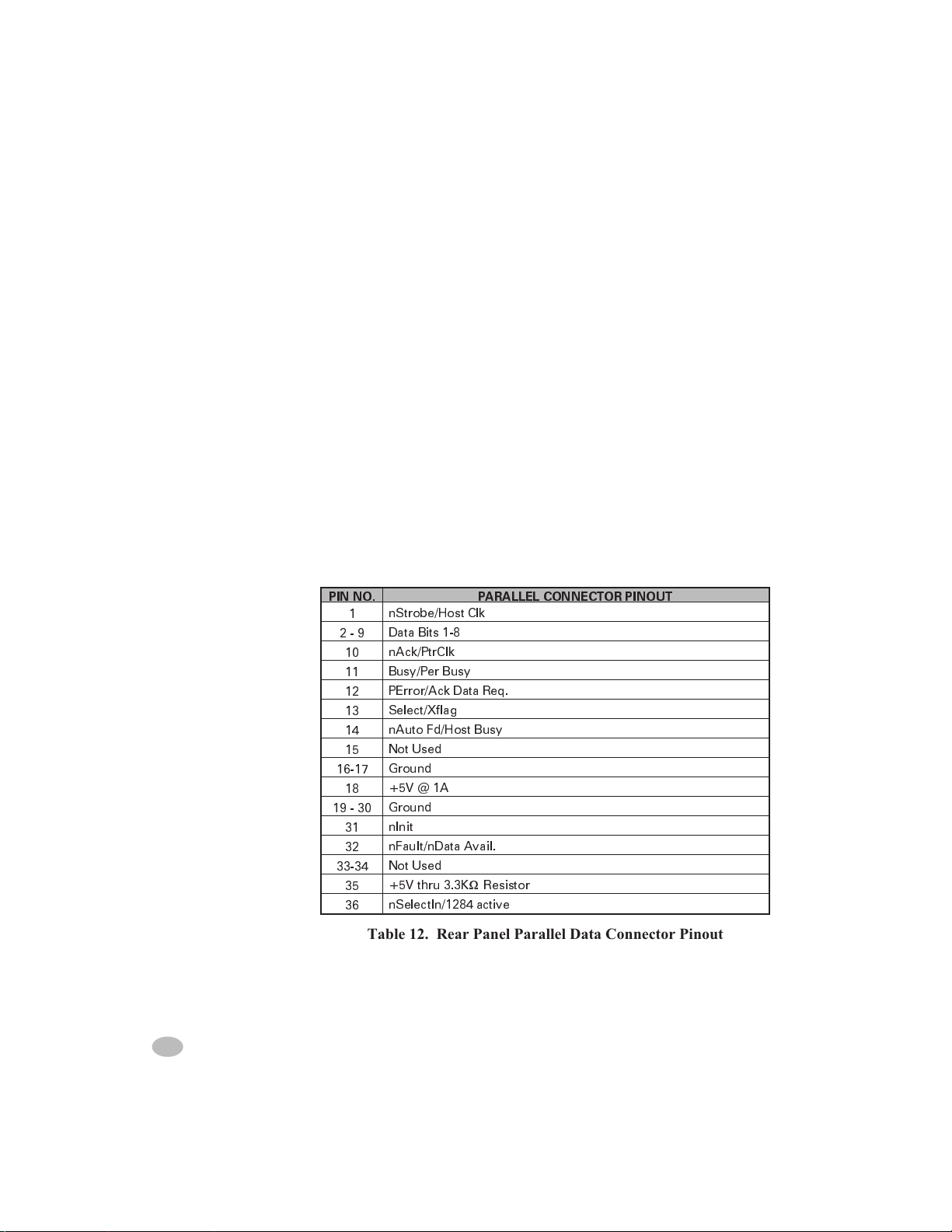
Parallel Data Communications
Table 12 illustrates the pin connections on the Bi-directional Parallel
connector at the rear of the printer.
Parallel Interface
The 8-Bit Parallel Data Interface supports IEEE 1284 bi-directional
parallel communications in “nibble mode”. The parallel interface provides a means of communication which is typically faster than the previously mentioned serial interface methods. In this method, the bits of
data which make up a character are sent all at one time over several
wires in the cable, one bit per wire.
Parallel Cabling Requirements
An IEEE 1284 compatable bi-directional parallel data cable is required
when this communication method is used. The required cable must
have a standard 36-pin parallel connector on one end which is plugged
into the mating connector located at the rear of the printer. The other
end of the cable connects to the printer connector at the host computer.
PIN NO. PARALLEL CONNECTOR PINOUT
nStrobe/Host Clk
1
2-9
16-17
19 - 30
33-34
Data Bits 1-8
nAck/PtrClk
10
Busy/Per Busy
11
PError/Ack Data Req.
12
Select/Xflag
13
nAuto Fd/Host Busy
14
Not Used
15
Ground
+5V @ 1A
18
Ground
nInit
31
nFault/nData Avail.
32
Not Used
+5V thru 3.3KWResistor
35
nSelectIn/1284 active
36
Table 12. Rear Panel Parallel Data Connector Pinout
74 Z Series™ User’s Guide
Page 83

Color profile: Disabled
Composite Default screen
Appendix C
AC Power Cord
Since many areas of the world have specific power requirements, an
AC Power Cord may not be included with your printer. Refer to Figure
30. A power cord must be provided by you that meets your local electrical requirements.
WARNING!! For personnel and equipment safety, always use
a three-prong plug with an earth ground connection to the
AC Power Source.
AC Power Cord Specifications
n
The overall length must be less than 9.8ft. (3.0 meters)
n
It must be rated for at least 5A, 250V.
n
The chassis ground (earth) MUST be connected to assure safety and
reduce electromagnetic interference. The ground connection is
handled by the third wire (earth) in the power cord.
n
The AC power plug and IEC320 connector must bear the
certification mark of at least one of the known international safety
organizations shown in Figure 30.
H:...uspiran2.vp
Thu Jun 25 11:20:47 1998
AC POWER
PLUG FOR
YOUR COUNTRY
3 CONDUCTOR
<HAR> CABLE
IEC 320
CONNECTOR
CONTACT
NEUTRAL
EARTH
LIVE
VIEW
+
R
Figure 30. AC Power Cord Requirements
Z Series™ User’s Guide 75
83
Page 84
Color profile: Disabled
Composite Default screen
Fuse Replacement
A user-replaceable AC Power Fuse is located just below the AC Power
Switch at the rear of the printer. The replacement fuse is a 3AG Fast
Blow style rated at 5 Amp/250 VAC
Before replacing the fuse, turn the AC Power Switch OFF and unplug
the AC Power Cable.
To replace the fuse, insert the tip of a flatblade screwdriver into the slot
in the end of the Fuse Holder End Cap. Press in slightly on the End Cap
and turn the screwdriver slightly counterclockwise. This will disengage
the End Cap from the Fuse Holder and permit removal of the fuse.
To install a new fuse, reverse the sequence.
Shipping
To ship the Z Series™ printer, remove all ribbon and media from the
supply and take-up spindles to prevent damage to the printer. Carefully
pack the printer in a suitable container to avoid damage during transit.
Whenever possible, use the original “carton within a carton” packing
materials from the factory. A shipping container can be purchased from
Zebra Technologies Corporation if the original packaging is lost or destroyed.
If you use a different container, package the printer carefully to avoid
damage.
CAUTION: When packaging the printer in a rigid container, use
shock mounts or shock-absorbing packing material.
Setting Darkness For “In-Spec” Bar Codes
All Direct Thermal and Thermal Transfer materials do not have the
same Darkness requirements. The best way to check for the proper
darkness setting is to use a Bar Code Verifier that actually measures
bars/spaces and will calculate the PCS ratio. Without the assistance of a
verifier, your eyes and/or the scanner to be used in the system, are the
best bet for picking the optimum darkness setting. The following is a
simple yet effective method for adjusting the darkness setting to print
“In Spec” bar codes. Refer to Figure 31 for sample bar codes.
76 Z Series™ User’s Guide
84
H:...uspiran2.vp
Thu Jun 25 11:20:47 1998
Page 85

Color profile: Disabled
Composite Default screen
1. Load media (and Ribbon if required) according to the appropriate Media Loading and Ribbon Loading Instructions found
in this User’s Guide. Insure the Print Method is appropriately
characterized for either Direct Thermal or Thermal Transfer.
2. To print a label for evaluation, use the following procedure:
A. With Power OFF, press and hold the FEED Key.
B. Turn the Printer Power ON, then release the FEED
Key.
C. The Printer will power up and begin printing test la-
bels.
3. Print a label, then press the PAUSE Key. The label will contain two bar codes as well as other printer information. Normal bar codes are printed in a horizontal format as they feed
out of the printer. Rotated bar codes are printed in a vertical
format.
4. Compare the test label printed, to the bar codes in Figure 31.
If the test label appears too light or too dark, refer to Appendix A and increase or decrease the DARKNESS Setting accordingly.
5. Resume printing by pressing the PAUSE Key again. Print a
few labels at the new setting and verify that proper “In Spec”
bar codes are being printed. Repeat steps 3, 4 and 5 until satisfied.
6. To terminate the printing of the test labels, press the PAUSE
Key, then epress the CANCEL Key.
Printing Conditions
Too Dark - Dark labels are fairly obvious. The normal bar code bars
increase in size, and the openings in small alphanumeric characters may
fill in with ink. It may be readable but not “In Spec”. Rotated bar code
bars and spaces will run together.
Slightly Dark - Slightly dark labels are not as obvious. The normal
bar code will be “In Spec”. Small character alphanumerics will be bold
and could be slightly filled in.The rotated bar code spaces are small
when compared to the “In Spec” code, possibly making the code unreadable.
H:...uspiran2.vp
Thu Jun 25 11:20:47 1998
Z Series™ User’s Guide 77
85
Page 86

Color profile: Disabled
Composite Default screen
Slightly Light - Slightly light labels are, in some cases, preferred to
slightly dark for “In Spec” bar codes. Both normal and rotated bar
codes will be “In Spec”, but small alphanumeric characters may not be
complete.
Too Light - Light labels are very obvious. Both normal and rotated
bar codes have incomplete bars and spaces. Small alphanumeric characters are unreadable.
In Spec - The “In Spec” bar code can only be confirmed by a verifier,
but it should exhibit some very visible characteristics. The normal bar
code will have complete, even bars and clear, distinct spaces. The rotated bar code will also have complete bars and clear distinct spaces.
Although it may not look as good as a slightly dark bar code, it will be
“In Spec”. In both normal and rotated styles, small alphanumeric characters will look complete.
Figure 31. Bar Code Examples
78 Z Series™ User’s Guide
86
H:...uspiran2.vp
Thu Jun 25 11:20:50 1998
Page 87
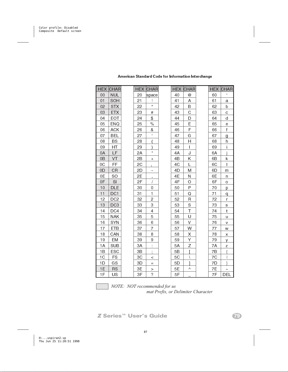
Color profile: Disabled
Composite Default screen
ASCII Code Chart
American Standard Code for Information Interchange
HEX CHAR HEX CHAR HEX CHAR HEX CHAR
00 NUL 20 space 40 @ 60
01 SOH 21 ! 41 A 61 a
02 STX 22 42 B 62 b
03 ETX 23 # 43 C 63 c
04 EOT 24 $ 44 D 64 d
05 ENQ 25 % 45 E 65 e
06 ACK 26 & 46 F 66 f
07 BEL 27 47 G 67 g
08 BS 28 ( 48 H 68 h
09 HT 29 ) 49 I 69 i
0A LF 2A * 4A J 6A j
0B VT 2B + 4B K 6B k
0C FF 2C , 4C L 6C l
0D CR 2D - 4D M 6D m
0E SO 2E . 4E N 6E n
0F SI 2F / 4F O 6F o
10 DLE 30 0 50 P 70 p
11 DC1 31 1 51 Q 71 q
12 DC2 32 2 52 R 72 r
13 DC3 33 3 53 S 73 s
14 DC4 34 4 54 T 74 t
15 NAK 35 5 55 U 75 u
16 SYN 36 6 56 V 76 v
17 ETB 37 7 57 W 77 w
18 CAN 38 8 58 X 78 x
19 EM 39 9 59 Y 79 y
1A SUB 3A : 5A Z 7A z
1B ESC 3B ; 5B [ 7B {
1C FS 3C < 5C \ 7C |
1D GS 3D = 5D ] 7D }
1E RS 3E > 5E ^ 7E ~
1F US 3F ? 5F _ 7F DEL
H:...uspiran2.vp
Thu Jun 25 11:20:51 1998
NOTE: NOT recommended for use as a Command
Prefix, Format Prefix, or Delimiter Character
Z Series™ User’s Guide 79
87
Page 88

Color profile: Disabled
Composite Default screen
80 Z Series™ User’s Guide
88
H:...uspiran2.vp
Thu Jun 25 11:20:51 1998
Page 89

Color profile: Disabled
Composite Default screen
Glossary
alphanumeric Indicating letters, numerals, and characters such as
punctuation marks.
backfeed When the printer pulls the media and ribbon (if used) back-
ward into the printer so that the beginning of the label to be printed
is properly positioned behind the printhead. Backfeed occurs when
operating the printer in tear-off, peel-off, or cutter mode.
bar code A code by which alphanumeric characters can be represented
by a series of adjacent stripes of different widths. Many different
code schemes exist, such as the universal product code (UPC) or
Code 39.
calibration (of a printer) A process in which the printer determines
some basic information needed to print accurately with a particular
media and ribbon combination. To do this, the printer feeds some
media and ribbon (if used) through the printer and senses whether
to use the direct thermal or thermal transfer print method,and (if
using non-continuous media) the length of individual labels or
tags.
character set The set of all letters, numerals, punctuation marks,
and other characters that can be expressed by a particular font or
barcode.
check digit A character added to a barcode symbol that indicates to
the scanner that it has read the symbol correctly.
continuous media Label or tagstock media that has no notch, gap, or
web (backing material only) to separate the labels or tags - the
media is one long piece of material.
core diameter The inside diameter of the cardboard core at the center
of a roll of media or ribbon.
cutter A device that can cut the media into individual labels or tags
immediately after it is printed.
H:...uspiran2.vp
Thu Jun 18 16:05:27 1998
Z Series™ User’s Guide 81
89
Page 90

Color profile: Disabled
Composite Default screen
diagnostics Information about which printer functions are not working
- used for troubleshooting printer problems.
die-cut labels See non-continuous media.
direct thermal A printing method in which the printhead presses
directly against the media. Heating the printhead elements causes a
discoloration of the heat-sensitive coating on the media. By selectively heating the printhead elements as the media moves past, an
image is printed onto the media. No ribbon is used with this printing method. Contrast this with thermal transfer.
direct thermal media Media that is coated with a substance which
reacts to the application of direct heat from the printhead to
produce an image.
fanfold media Media that comes folded in a rectangular stack.
Contrast this with roll media.
font A complete set of alphanumeric characters in one style of type.
Ex: CG Times, CG Triumvirate Bold Condensed.
ips “inches-per-second” The speed at which the label or tag is
printed. Zebra offers printers that can print from 2 ips to 12 ips.
label An adhesive-backed piece of paper, plastic, or other material on
which information is printed.
label available sensor For printers equipped with the Peel-Off Option,
this sensor detects a printed label waiting to be taken or “picked”
by the operator. While it detects this label, the printer will not print
additional labels. Once the label has been removed from the
printer,the next label is printed. Also called the “take-label sensor”.
label backing (label liner) The material on which labels are affixed
during manufacture and which is discarded or recycled by the
end-users.
media Material onto which data is printed by the printer. Types of
media include: tagstock, die-cut labels, continuous (with and without backing material), fanfold, and roll.
media sensor This sensor is located behind the printhead to detect the
presence of media and, for non-continuous media, the position of
the web, hole, or notch used to indicate the start of each label.
media supply hanger The stationary arm that supports the media roll.
82 Z Series™ User’s Guide
90
H:...uspiran2.vp
Thu Jun 18 16:05:27 1998
Page 91

Color profile: Disabled
Composite Default screen
non-continuous media Consumable printing stock which contains an
indication of where one label/printed format ends and the next one
begins. Examples are die-cut labels, notched tagstock, and stock
with black mark registration marks
non-volatile memory Electronic memory that retains data even when
the power to the printer is turned OFF.
print speed The speed at which printing occurs. For thermal transfer
printers, this speed is expressed in terms of ips (inches per second).
Zebra offers printers that can print from 2 ips to 12 ips.
printhead wear The degradation of the surface of the printhead and/or
the print elements over time. Heat and abrasion can cause printhead wear. Therefore, to maximize the life of the printhead, use the
lowest print darkness setting (sometimes called burn temperature
or head temperature) and the lowest printhead pressure necessary
to produce good print quality. In the thermal transfer printing
method, use ribbon that is as wide or wider than the media, to
protect the printhead from the rough media surface.
registration Alignment of printing with respect to the top of a label or
tag.
ribbon A band of material consisting of a base film coated with wax
or resin “ink”. The inked side of the material is pressed by the
printhead against the media. The ribbon transfers ink onto the
media when heated by the small elements within the printhead.
Zebra ribbons have a coating on the back that protects the printhead from wear.
ribbon wrinkle A wrinkling of the ribbon caused by improper align-
ment or improper printhead pressure. This wrinkle can cause voids
in the print and/or the used ribbon to rewind unevenly. This condition should be corrected by performing adjustment procedures.
roll media Media that comes supplied rolled onto a core (usually card-
board). Contrast this with fanfold media.
supplies A general term for media and ribbon.
tag A type of media having no adhesive backing but featuring a hole
or notch by which the tag can be hung on something. Tags are usually made of cardboard or other durable material.
H:...uspiran2.vp
Thu Jun 18 16:05:28 1998
Z Series™ User’s Guide 83
91
Page 92

Color profile: Disabled
Composite Default screen
take label sensor See label available sensor.
thermal direct See direct thermal.
thermal transfer A printing method in which the printhead presses
an ink or resin coated ribbon against the media. Heating the printhead elements causes the ink or resin to transfer onto the media.
By selectively heating the printhead elements as the media and
ribbon move past, an image is printed onto the media. Contrast this
with direct thermal.
void A space where printing should have occurred, but did not due to
an error condition such as wrinkled ribbon or faulty print elements.
A void can cause a printed bar code symbol to be read incorrectly
or not at all.
84 Z Series™ User’s Guide
92
H:...uspiran2.vp
Thu Jun 18 16:05:28 1998
Page 93

Color profile: Disabled
Composite Default screen
Index
A
AC Power 2
Adjustments
Media Sensor Position 9
Printhead Pressure 24
ASCII Control Codes
XOFF (DC3) 71
XON (DC1) 71
C
Calibration 17
Caution
Ribbon Width 8
Shipping 74
Unshielded Cables 71
CCITT V.24 71
Cleaning 19
Cutter Module 22
Platen 20
Printhead 20
Recommended Schedule 19
Sensors 20
Communication Interfaces 69
IEEE 1284 Parallel 72
RS-232 Serial 70
RS-485 Serial 71
Communications 2
Configuration 55
Factory Settings 3, 4
Configuration Label 39
H:...uspiran2.vp
Thu Jun 18 16:05:50 1998
Z Series™ User’s Guide 85
93
Page 94

Color profile: Disabled
Composite Default screen
D
Damage Report 1
DIP Switches 55
DTR (Data Terminal Ready) 71
E
EIA RS232 71
Electrical Noise 69
Error Conditions 46
LCD Display 27
F
Factory Defaults 44
FCC Rules and Regulations 71
Front Panel
Deluxe 27, 59
Standard 55
Front Panel Control Keys 58
Front Panel Keys 13
Front Panel LEDs 14
Fuse Replacement 73
G
Glossary 79
I
IN SPEC Bar Codes 74
Initialization
Flash Memory 45
PCMCIA Card 45
L
Liquid Crystal Display 13, 27
Loading
Media 5
Ribbon 7
Lubrication 24
86 Z Series™ User’s Guide
94
H:...uspiran2.vp
Thu Jun 18 16:05:51 1998
Page 95

Color profile: Disabled
Composite Default screen
M
Maintenance 1
Media
Continuous 9
Fanfold 6
Non-Continuous 9
Roll 6
Media Alignment
Power Peel 25
Power Rewind 25
Media Guide 6, 29, 31, 32
Media Loading 5
Media Sensor
Operation 9
Position 9
Media Sensors 9
Media Supply Guide 6, 29, 31, 32
Media Supply Hanger 6, 29, 31, 32
O
Optional Fonts 53
Options
Communication 33
Cutter 31
DRAM Memory 33
Flash Memory 33
PCMCIA Memory Card 33
Power Peel 28
Power Rewind 28
Value Peel 30
P
Power ON Self Test 35
Printer Configuration 59
Printer Configuration Label 39
Printer Options 28
Printer Power 2
Printer Specifications 47, 48
Printhead Pressure 24
Z Series™ User’s Guide 87
H:...uspiran2.vp
Thu Jun 18 16:05:51 1998
95
Page 96

Color profile: Disabled
Composite Default screen
R
Reporting Damage 1
Ribbon Loading 7
Ribbon Removal 8
Ribbon Supply Spindle 8
Ribbon Takeup Spindle 8
RS-232 70
Chassis Ground 69
DSR (Data Set Ready) 69
DTR (Data Terminal Ready) 69
RTS (Request To Send) 69
RXD (Receive Data) 69
Signal Ground 69
TXD (Transmit Data) 69
RS-485 71
Input A (+) 69
Input B (-) 69
Output A (+) 69
Output B (-) 69
Signal Ground 69
RTS (Request To Send) 71
S
Self-Test Labels 38
Self-Tests
Power ON 35
Printer 38
Sensor Positioning 9
Settings
Communicaitons 56
Darkness 58
Operating Modes 57
Print Darkness 58
Shipping 74
Shipping Container 74
Shipping Damage 1
Specifications 48
Standard Fonts 51
Storage and Reshipping 71
Switch Settings 55
88 Z Series™ User’s Guide
96
H:...uspiran2.vp
Thu Jun 18 16:05:51 1998
Page 97

Color profile: Disabled
Composite Default screen
T
Troubleshooting 35
U
Unpacking 1
W
Warning
AC Power 2, 73
Earth Ground 2, 73
Equipment Safety 2, 73
Personnel Safety 2, 73
Z
ZPL II 1, 17, 50
ZPL II Instructions
Changing Prefixes & Delimiters (^CC, ^CD, ^CT) 37
Configuration Update (^JUS) 44
Label Length (^LL) 9
H:...uspiran2.vp
Thu Jun 18 16:05:51 1998
Z Series™ User’s Guide 89
97
Page 98

Color profile: Disabled
Composite Default screen
90 Z Series™ User’s Guide
98
H:...uspiran2.vp
Thu Jun 18 16:05:52 1998
 Loading...