

Page 1

VC70N0 Vehicle Computer
Product Reference Guide
Page 2

Page 3

VC70N0 Vehicle Computer
Product Reference Guide
72-164686-05
Revision A
December 2020
Page 4

ii VC70N Vehicle Computer Product Reference Guide
No part of this publication may be reproduced or used in any form, or by any electrical or mechanical means,
without permission in writing. This includes electronic or mechanical means, such as photocopying, recording,
or information storage and retrieval systems. The material in this manual is subject to change without notice.
The software is provided strictly on an “as is” basis. All software, including firmware, furnished to the user is on
a licensed basis. We grant to the user a non-transferable and non-exclusive license to use each software or
firmware program delivered hereunder (licensed program). Except as noted below, such license may not be
assigned, sublicensed, or otherwise transferred by the user without prior written consent. No right to copy a
licensed program in whole or in part is granted, except as permitted under copyright law. The user shall not
modify, merge, or incorporate any form or portion of a licensed program with other program material, create a
derivative work from a licensed program, or use a licensed program in a network without written permission.
The user agrees to maintain copyright notice on the licensed programs delivered hereunder, and to include the
same on any authorized copies it makes, in whole or in part. The user agrees not to decompile, disassemble,
decode, or reverse engineer any licensed program delivered to the user or any portion thereof.
We reserve the right to make changes to any software or product to improve reliability, function, or design. We
do not assume any product liability arising out of, or in connection with, the application or use of any product,
circuit, or application described herein.
No license is granted, either expressly or by implication, estoppel, or otherwise under any of our intellectual
property rights. An implied license only exists for equipment, circuits, and subsystems contained in our
products.
Warranty
Subject to the terms of Zebra hardware warranty statement, the VC70 Vehicle Computer products are
warranted against defects in workmanship and materials for a period of one year from the date of shipment.
For the complete Zebra hardware product warranty statement, go to:
Revision History
Changes to the original manual are listed below:
Change Date Description
-05 Rev A 12/2020 Replaced master/slave references with central/peripheral (for Bluetooth) and
-04 Rev A 1/2019 Correct DC power cable part number.
-03 Rev A 7/2018 Update memory size.
-02 Rev C 8/2016 Correct COM port on page 5-15, step 15. (Change from COM 9 to COM1).
-02 Rev B 1/2016 Add Caution not to use tool when connecting cables to COM and USB ports.
-02 Rev A 2/7/2015 Zebra Re-branding. Update accessory table.
-01 Rev C 09/01/2014 Revision C
www.zebra.com/warranty
controller/follower (for non-Bluetooth)
-01 Rev B 09/19/13 Revision B Release
-01 Rev A 11/30/12 Initial release.
Page 5

iii
Page 6

iv VC70N Vehicle Computer Product Reference Guide
Page 7

Table of Contents
Warranty ............................................................................................................................................... ii
Revision History.................................................................................................................................... ii
About This Guide
Introduction ........................................................................................................................................... xi
Documentation Set ......................................................................................................................... xi
Configurations....................................................................................................................................... xii
Software Versions........................................................................................................................... xii
Chapter Descriptions ............................................................................................................................ xiii
Notational Conventions......................................................................................................................... xiv
Related Documents and Software ........................................................................................................ xiv
Service Information............................................................................................................................... xiv
Returning the Vehicle Computer for Service................................................................................... xv
Chapter 1: Getting Started
Introduction .......................................................................................................................................... 1-1
Unpacking the VC70 ............................................................................................................................ 1-1
Features ............................................................................................................................................... 1-1
Accessories ......................................................................................................................................... 1-4
Chapter 2: Installation
Introduction .......................................................................................................................................... 2-1
Electrical Power Wiring ........................................................................................................................ 2-2
Forklifts and Trucks with 12V, 24V, 36V and 48V Batteries .................................................... 2-3
Ignition Sensing ............................................................................................................................. 2-5
VC70 Power States ............................................................................................................................. 2-6
Installing the VC70 on a Cart, a Wall, or a Desktop ............................................................................ 2-7
Mounting the Bracket on a Desktop ............................................................................................... 2-7
Connecting the Vehicle Computer to AC Power ............................................................................ 2-8
Installing the DC Power Supply (PSU) on the VC70 ........................................................................... 2-9
Installing a Micro SD Card ................................................................................................................... 2-10
RAM Mount Installation ........................................................................................................................ 2-11
Page 8

vi VC5090 Vehicle Computer Product Reference Guide
U-Mount Installation ............................................................................................................................. 2-13
Installing the VC70 on a Forklift ........................................................................................................... 2-14
Positioning the Vehicle Computer .................................................................................................. 2-14
U-Mount Installation Template ................................................................................................. 2-16
Mounting onto an Over-Head Cross-Beam Example ............................................................... 2-17
Mounting onto an Over-Head Cage Example .......................................................................... 2-17
Mounting on a Dashboard or Horizontal Surface Example ...................................................... 2-19
Installing the Optional QWERTY/AZERTY Keyboard .......................................................................... 2-20
Installing the Optional VC5090 Keyboard on the VC70 ....................................................................... 2-22
Installing a Numeric Keyboard ............................................................................................................. 2-23
Keyboard Protection Grill Installation ................................................................................................... 2-25
Installing the Scanner Mount ............................................................................................................... 2-26
Installing a Stubby Antenna ................................................................................................................. 2-27
Installing the External Roof-mounted Antenna .................................................................................... 2-28
Connecting Accessories ...................................................................................................................... 2-29
Connecting an External Speaker to the Vehicle Computer ................................................................. 2-29
Installing an External Microphone Mount ............................................................................................. 2-29
Chapter 3: Operating the VC70
Introduction .......................................................................................................................................... 3-1
Control Panel Applications ................................................................................................................... 3-1
Quick Access Panel ............................................................................................................................. 3-4
Power Button ................................................................................................................................. 3-4
Charging LED ................................................................................................................................ 3-4
COMM LED .................................................................................................................................... 3-5
Brightness and Speaker Buttons ................................................................................................... 3-6
Function LED ................................................................................................................................. 3-6
Programmable (“P”) Keys .............................................................................................................. 3-6
Using the Keyboard ............................................................................................................................. 3-6
Soft Input Panel (SIP) Keyboards .................................................................................................. 3-6
Keyboard Functionality .................................................................................................................. 3-10
Adjusting the Brightness ...................................................................................................................... 3-12
Controlling Screen Brightness ....................................................................................................... 3-12
Controlling the External Keyboards Backlight ................................................................................ 3-13
Adjusting the Volume ........................................................................................................................... 3-13
Taskbar ................................................................................................................................................ 3-14
Start Button .................................................................................................................................... 3-15
Programs Menu ............................................................................................................................. 3-15
Desktop Button .............................................................................................................................. 3-16
Task Manager and Properties ........................................................................................................ 3-16
Task Manager .......................................................................................................................... 3-16
Properties ................................................................................................................................. 3-17
Using Voice Communication ................................................................................................................ 3-18
Resetting the Vehicle Computer .......................................................................................................... 3-19
Performing a Warm Boot ............................................................................................................... 3-19
Performing a Cold Boot .................................................................................................................. 3-19
Boot Persistence ............................................................................................................................ 3-20
Power Status ....................................................................................................................................... 3-22
Power On ....................................................................................................................................... 3-22
Page 9

Table of Contents vii
Low Power Mode ........................................................................................................................... 3-22
Methods of Suspension ........................................................................................................... 3-22
Critical Suspension ........................................................................................................................ 3-22
Waking the Vehicle Computer ....................................................................................................... 3-23
Reduced Power Consumption ....................................................................................................... 3-23
Controlling the Display ......................................................................................................................... 3-25
Using the Display ........................................................................................................................... 3-25
Using the Keyboard ....................................................................................................................... 3-26
Screen Lock ................................................................................................................................... 3-28
Checking Backup Battery Status ......................................................................................................... 3-29
Disconnecting the Backup Battery ................................................................................................. 3-29
Checking the Status of the Backup Battery ................................................................................... 3-29
Sensors Configuration ......................................................................................................................... 3-30
Desiccant Warning ......................................................................................................................... 3-30
TouchPanel Heater ........................................................................................................................ 3-32
Real Time Log ..................................................................................................................................... 3-32
Shock Events Log ................................................................................................................................ 3-33
Chapter 4: DataWedge Scanner Connection
Introduction .......................................................................................................................................... 4-1
Scanner Connection Method ............................................................................................................... 4-2
Scanner/SSI Firmware Compatibility ................................................................................................... 4-2
Scanner/SSI Firmware Compatibility ................................................................................................... 4-3
Installing a Scanner ............................................................................................................................. 4-3
Connect LS3408-ER Corded Scanner to a Serial Port of the VC70 (SSI) ............................... 4-4
Connect DS3508-ER Corded Scanner to a Serial Port of the VC70 (SSI) .............................. 4-8
Connect LS3408-ER Corded Scanner to a Serial Port of the VC70 (Serial) ........................... 4-11
Connect DS3508-ER Corded Scanner to a Serial Port of the VC70 (Serial) ........................... 4-14
Connect a Bluetooth Scanner DS3578 Directly to the VC70 (SPP Profile) ............................. 4-19
Connect a Bluetooth Scanner LS3578 Directly to the VC70 (SPP Profile) .............................. 4-25
Connect a Bluetooth Scanner RS507 Directly to the VC70 (Scan Profile) .............................. 4-29
Connect a Bluetooth Scanner RS507 Directly to the VC70 (SPP Profile) ............................... 4-31
Chapter 5: TelnetCE Configuration
Introduction .......................................................................................................................................... 5-1
Scanner Connection Method ............................................................................................................... 5-2
Scanner/SSI Firmware Compatibility ................................................................................................... 5-3
Wavelink TelnetCE .............................................................................................................................. 5-3
Connect LS3408-ER Corded Scanner to a Serial Port of the VC70 (SSI) ............................... 5-4
To connect a scanner: ) ........................................................................................................... 5-4
Connect DS3508-ER Corded Scanner to a Serial Port of the VC70 (SSI) .............................. 5-8
Connect LS3408-ER Corded Scanner to a Serial Port of the VC70 (Serial) ........................... 5-11
Connect DS3508-ER Corded Scanner to a Serial Port of the VC70 (Serial) ........................... 5-20
Connect LS3408-ER Scanner to USB Port of the VC70 (HID) ................................................ 5-28
Connect LS3408-ER Corded Scanner to USB Port of the VC70 (Scan Handlers) .................. 5-29
Connect DS3508-ER Scanner to USB Port of the VC70 (HID) ............................................... 5-36
Connect DS3508-ER Serial Scanner to USB Port of the VC70 (Scan Handlers) .................... 5-38
Connect a Bluetooth Scanner RS507 Directly to the VC70 (Scan Profile) .............................. 5-44
Page 10

viii VC5090 Vehicle Computer Product Reference Guide
Connect a Bluetooth Scanner RS507 Directly to the VC70 (SPP Profile) ............................... 5-46
Connect a Bluetooth Scanner DS3578 Directly to the VC70 (SPP Profile) ............................. 5-54
Connect a Bluetooth Scanner LS3578 Directly to the VC70 (SPP Profile) .............................. 5-63
Chapter 6: Wireless LAN Applications
Introduction .......................................................................................................................................... 6-1
Signal Strength Icon ............................................................................................................................ 6-2
Turning the WLAN Radio On and Off .................................................................................................. 6-3
With Fusion .................................................................................................................................... 6-3
Find WLANs Application ...................................................................................................................... 6-3
Chapter 7: Using Bluetooth
Introduction .......................................................................................................................................... 7-1
Adaptive Frequency Hopping .............................................................................................................. 7-1
Security ................................................................................................................................................ 7-2
Turning the Bluetooth Radio Mode On and Off ................................................................................... 7-2
Disabling Bluetooth ........................................................................................................................ 7-2
Enabling Bluetooth ......................................................................................................................... 7-3
Bluetooth Power States ................................................................................................................. 7-4
Cold Boot ................................................................................................................................. 7-4
Warm Boot ............................................................................................................................... 7-4
Low Power ............................................................................................................................... 7-4
Pairing Cordless Scanners .................................................................................................................. 7-4
Discovering Bluetooth Device(s) .......................................................................................................... 7-4
File Transfer Services .................................................................................................................... 7-7
Create New File or Folder ........................................................................................................ 7-8
Delete File ................................................................................................................................ 7-8
Get File .................................................................................................................................... 7-9
Put File ..................................................................................................................................... 7-9
Connect to Internet Using Access Point ........................................................................................ 7-9
OBEX Object Push Services .......................................................................................................... 7-9
Send a Picture ......................................................................................................................... 7-10
Headset Services ........................................................................................................................... 7-11
Serial Port Services ....................................................................................................................... 7-11
Personal Area Network Services ................................................................................................... 7-12
Bluetooth Settings ................................................................................................................................ 7-12
Device Info Tab .............................................................................................................................. 7-12
Services Tab .................................................................................................................................. 7-13
File Transfer Service ................................................................................................................ 7-14
Personal Area Networking Service .......................................................................................... 7-14
Serial Port Service ................................................................................................................... 7-15
Headset Service ....................................................................................................................... 7-16
Security Tab ................................................................................................................................... 7-16
Discovery Tab ................................................................................................................................ 7-16
Virtual COM Port Tab ..................................................................................................................... 7-17
Miscellaneous Tab ......................................................................................................................... 7-18
Page 11

Table of Contents ix
Chapter 8: Sync with Host Computer
Introduction .......................................................................................................................................... 8-1
Installing the Synchronization Software ............................................................................................... 8-2
Vehicle Computer Setup ...................................................................................................................... 8-2
Setting Up an ActiveSync Connection on the Host Computer (Windows XP) ..................................... 8-3
Setting up a Partnership ................................................................................................................ 8-4
Setting Up an Windows Mobile Device Center Connection on the Host Computer (Windows 7) ........ 8-6
Setting up a Partnership ................................................................................................................ 8-7
Chapter 9: Application Development and Deployment
Introduction .......................................................................................................................................... 9-1
Software Installation on Development PC (Application Development) ................................................ 9-1
Platform SDK ................................................................................................................................. 9-1
Zebra Developer Kit ....................................................................................................................... 9-2
Installing Other Development Software ......................................................................................... 9-2
Software Installation on Vehicle Computer .......................................................................................... 9-2
ActiveSync ..................................................................................................................................... 9-2
Micro SD Card ............................................................................................................................... 9-4
Flash Storage ...................................................................................................................................... 9-4
FFS Partitions ................................................................................................................................ 9-4
Working with FFS Partitions ........................................................................................................... 9-5
RegMerge.dll ............................................................................................................................ 9-5
CopyFiles ................................................................................................................................. 9-5
Non-FFS Partitions ........................................................................................................................ 9-6
Chapter 10: Staging and Provisioning
Introduction .......................................................................................................................................... 10-1
MSP 3 Agent .................................................................................................................................. 10-1
AppCenter ...................................................................................................................................... 10-2
Chapter 11: Software Configuration
Introduction .......................................................................................................................................... 11-1
VC70 Operating System - Image Upgrade .......................................................................................... 11-1
Updating the Image ........................................................................................................................ 11-1
Monitor Mode ........................................................................................................................... 11-1
To Update the Image ............................................................................................................... 11-1
OSupgrade Mode ........................................................................................................................... 11-2
Switch Between Microsoft and StoneStreet One (SS1) Bluetooth Stack ............................................ 11-3
Often Used Registry Settings .............................................................................................................. 11-3
Power Suspend .............................................................................................................................. 11-3
COM1 Power Output to Scanner ................................................................................................... 11-4
COM2 Power Output to Scanner ................................................................................................... 11-4
External Antenna ........................................................................................................................... 11-4
Ignition Timeout ............................................................................................................................. 11-5
Registry Values for P1/P2/P3/P4 Keys .......................................................................................... 11-5
Disabling the Fusion RX Sensitivity Degradation ........................................................................... 11-6
VC70N0 WinCE 7.0 Registry Settings for Control Panel Applets .................................................. 11-6
Page 12

x VC5090 Vehicle Computer Product Reference Guide
Screen locking feature ............................................................................................................. 11-6
Speaker control ........................................................................................................................ 11-8
Setting COM5 as Default Serial Port ............................................................................................. 11-9
Disable SIP from Auto-Launching ........................................................................................................ 11-9
Force Warm Boot or Cold Boot After Resuming From Critical Suspension ......................................... 11-9
Chapter 12: Maintenance
Introduction .......................................................................................................................................... 12-1
Maintaining the Vehicle Computer ....................................................................................................... 12-1
Returning the Vehicle Computer for Service .................................................................................. 12-2
Replacing the Desiccant Bag ......................................................................................................... 12-2
Replacing the Backup Battery ........................................................................................................ 12-3
Troubleshooting ................................................................................................................................... 12-4
Appendix A: Specifications
Technical Specifications ...................................................................................................................... A-1
Vehicle Computer .......................................................................................................................... A-1
Vehicle Computer Connectors ............................................................................................................. A-3
Glossary
Page 13

About This Guide
Introduction
The VC70 Product Reference Guide provides information about the VC70 vehicle computer using Microsoft®
Windows® CE 7.0 operating system and its accessories.
NOTE
Screens and windows pictured in this guide are samples and can differ from actual screens.
Documentation Set
The documentation set for the VC70 is divided into guides that provide information for specific user needs.
•
VC70 Quick Reference Guide - describes how to install and use the VC70 vehicle computer.
•
VC70 Product Reference Guide - provides an in-depth description on how to use and setup the VC70
vehicle computer and its accessories.
•
Microsoft Application Guide - describes how to use Microsoft developed applications that reside on the
VC70 vehicle computer.
•
Zebra Application Guide - describes how to use Zebra developed applications available for the VC70
vehicle computer.
•
EMDK Help File - provides API information for writing applications.
Page 14
xii VC70 Vehicle Computer Product Reference Guide
Configurations
This guide covers the following configurations:
Configuration Radios Display Memory
VC70 Full Screen WLAN:
802.11a/b/g/n
WPAN: Bluetooth
10.4” XGA
1024 x 768
Switchable to
SVGA
800x600
(4:3 format)
1 GB DDR2
volatile memory,
2 GB EMMC non
volatile memory
Data
Capture
Optional
Scanner
OS Keypad
Windows
CE 7.0
Professional
Optional USB
QWERTY or
AZERTY
keyboard
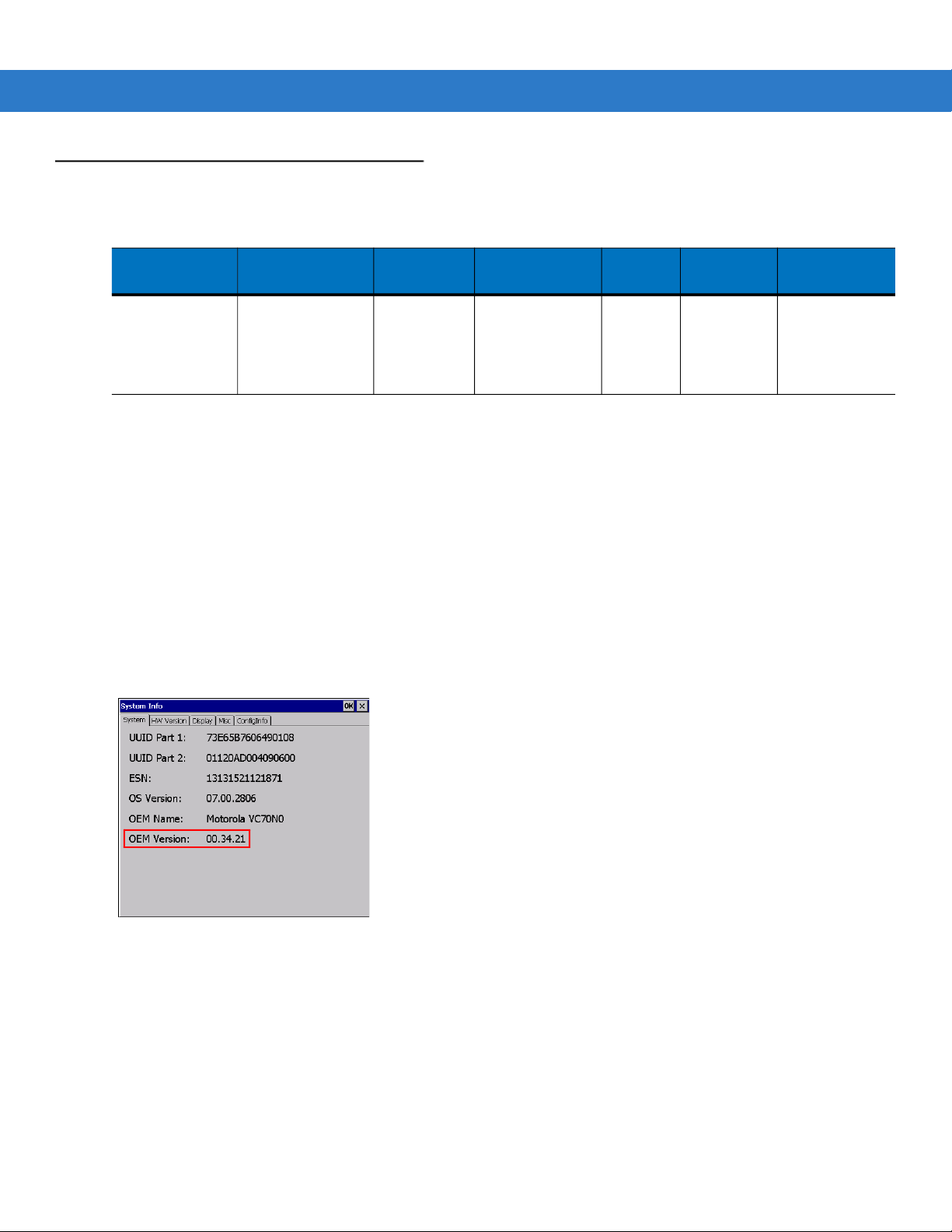
Software Versions
This guide covers various software configurations and references are made to operating system or software
versions for:
•
OEM version
•
Fusion version.
OEM Software
To determine the OEM software version:
Start > Settings > Control Panel > System Information icon > System tab.
Tap
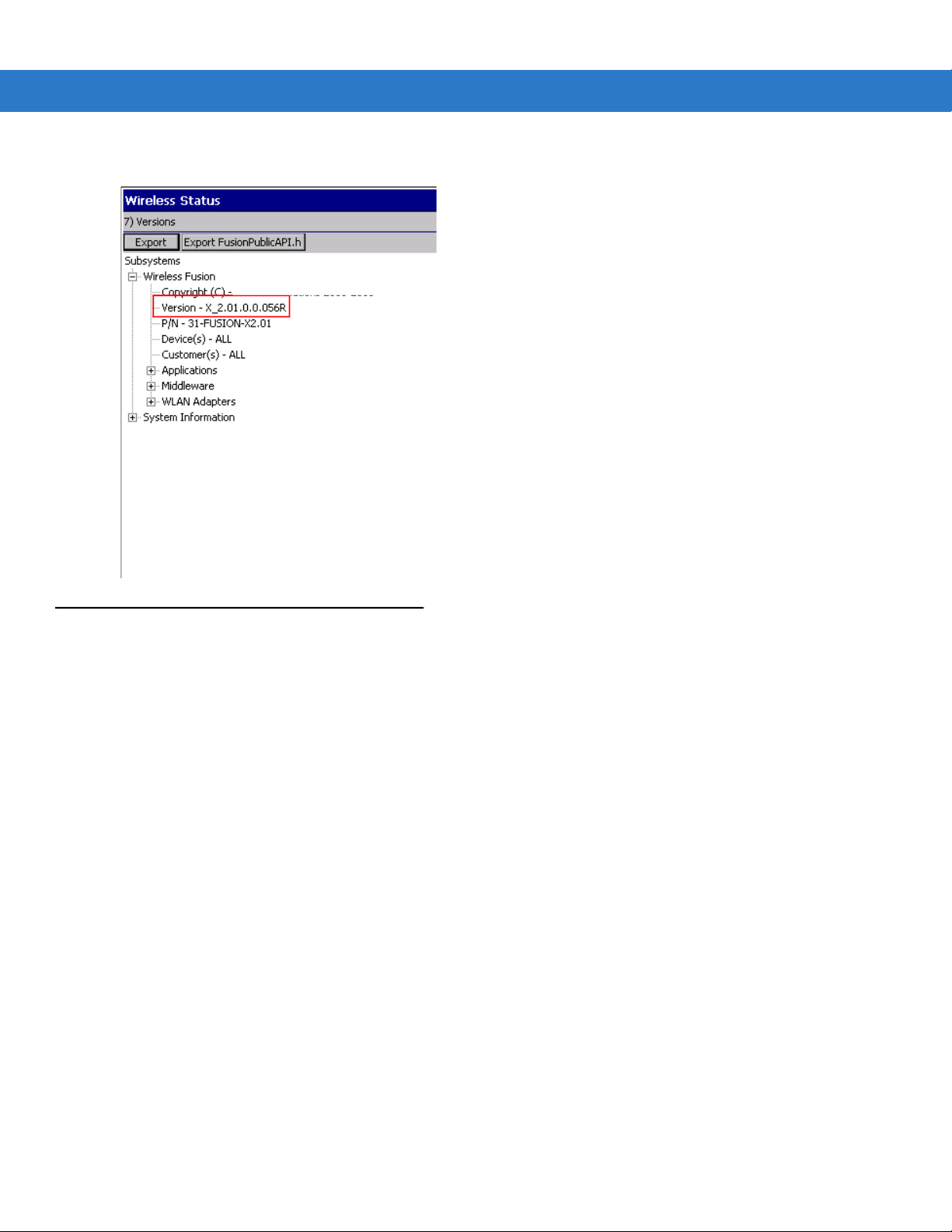
Fusion Software
To determine the Fusion software version:
Tap Fusion icon > Wireless Status > Versions.
Page 15
© 2014 Symbol Technologies, Inc.
About This Guide xiii
Chapter Descriptions
Topics covered in this guide are as follows:
•
Chapter 1, Getting Started, provides information on getting the vehicle computer up and running for the first
time.
•
Chapter 2, Installation, provides instructions for installing the vehicle computer in a forklift, on a wall or on a
desktop. Provides instructions for installing accessories.
•
Chapter 3, Operating the VC70, explains how to use the vehicle computer. This includes instructions for
powering on and resetting the vehicle computer, entering and capturing data.
•
Chapter 4, DataWedge Scanner Connection, describes how to install the scanners and accessories for the
VC70 vehicle computer.
•
Chapter 5, TelnetCE Configuration, provides instructions required for connecting serial scanners in a
Wavelink TelnetCE session via the VC70 vehicle computer
•
Chapter 6, Wireless LAN Applications, provides instructions for using and configuring the mobile computer
on a wireless network.
•
Chapter 7, Using Bluetooth, explains how to use Bluetooth functionality on the vehicle computer.
•
Chapter 8, Sync with Host Computer, provides instructions for installing and configuring ActiveSync.
•
Chapter 9, Application Development and Deployment, provides instructions for installing the EMDK for C on
the host computer and downloading software files to the vehicle computer.
•
Chapter 10, Staging and Provisioning, provides instructions for staging and provisioning the vehicle
computer.
•
Chapter 11, Software Configuration, includes special configuration instruction for third party software used
with the vehicle computer.
Page 16

xiv VC70 Vehicle Computer Product Reference Guide
•
Chapter 12, Maintenance, includes instructions on cleaning and storing the vehicle computer, and provides
troubleshooting solutions for potential problems during vehicle computer operation.
•
Appendix A, Specifications, includes a table listing the technical specifications for the vehicle computer.
Notational Conventions
The following conventions are used in this document:
•
“Vehicle computer” refers to the VC70 series of vehicle computers.
•
Italics are used to highlight the following:
• Chapters and sections in this and related documents.
•
Bold text is used to highlight the following:
• Key names on a keyboard
• Button names on a screen
• Dialog box, window and screen names
• Drop-down list and text box names
• Check box and radio button names
• Icons on a screen.
•
Bullets (•) indicate:
• Action items
• Lists of alternatives
• Lists of required steps that are not necessarily sequential.
•
Sequential lists (e.g., those that describe step-by-step procedures) appear as numbered lists.
Related Documents and Software
The following documents provide more information about the VC70 vehicle computers.
•
VC70 Quick Reference Guide, p/n 72-76346-xx
For the latest version of this guide and all guides, go to: http://www.zebra.com/support.
Service Information
If you have a problem with your equipment, contact Zebra support for your region. Contact information is available
at: http://www.zebra.com/support.
When contacting support, please have the following information available:
•
Serial number of the unit
•
Model number or product name
•
Software type and version number.
Zebra responds to calls by email, telephone or fax within the time limits set forth in support agreements.
Page 17

About This Guide xv
If your problem cannot be solved by Zebra support, you may need to return your equipment for servicing and will
be given specific directions. Zebra is not responsible for any damages incurred during shipment if the approved
shipping container is not used. Shipping the units improperly can possibly void the warranty.
If you purchased your Zebra business product from a Zebra business partner, contact that business partner for
support.
Returning the Vehicle Computer for Service
NOTE
In the event, the vehicle computer needs to be shipped to Zebra for repair or maintenance, it is essential that
the user perform the following steps to electrically disconnect the internal backup battery:
1. Disconnect the power cable from the VC70. The VC70 will continue to work on backup battery power.
2. Perform cold boot (Performing a Cold Boot on page 3-19). The backup battery will stop powering the VC70.
Page 18

xvi VC70 Vehicle Computer Product Reference Guide
Page 19

Chapter 1 Getting Started
Introduction
The VC70 is Zebra ultra-rugged forklift mounted computer. It is designed to maximize productivity in harsh
environments. Its rugged construction and high-performance wireless networking enables real-time data access
and collection in a wide range of environments — from the loading dock and freezer to the warehouse.
The VC70’s compact design improves visibility and reduces safety concerns while retaining large screen size
(10.4”). Its 802.11 a/b/g/n WLAN provides real-time information that improves decision making, reduces errors, and
enhances productivity. Its rugged design with integrated shock-mount and MIL-STD 810 military rating for shock
and vibration ensures dependable operation in challenging environments. Its IP66 sealing, display, defroster and
wide temperature range ensures operation in and out of -30
With its high-resolution and high-brightness display, the VC70 provides the user access to more information in low
ambient light warehouse and outdoors.
The VC70 accessories allow backward compatibility with the VC5090 for easy and gradual migration.
o
C freezer storage warehouse.
Unpacking the VC70
When you remove the vehicle computer from its box, save the box and shipping material in case you need to ship
or store the vehicle computer. Check the contents of the box against the invoice for completeness and contact your
local Zebra service representative if there is a problem.
The VC70 shipping box contains:
•
vehicle computer
•
VC70 Quick Reference Guide
Features
The VC70 has the following features:
•
Integrated 802.11a/b/g/n wireless LAN radio
Page 20
1 - 2 VC70 Vehicle Computer Product Reference Guide
•
Windows® CE 7.0 Professional Operating System
•
TI OMAP4430 processor at 1GHz in turbo mode CPU
•
1 GB DDR2 volatile memory, 2 GB EMMC non volatile memory
•
10.4” XGA 1024 x 768, Switchable to SVGA 800x600, (4:3 format) color display
•
Wireless and wired printing
•
Integrated antennas
•
Integrated speaker.
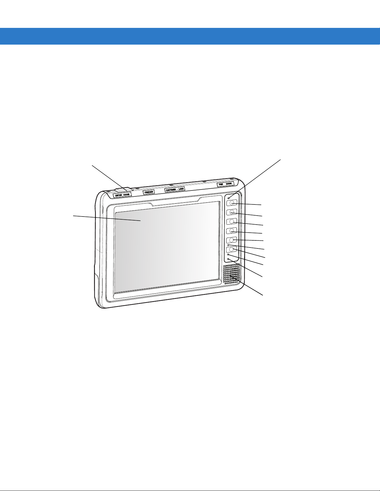
Antenna Port for
Optional External
Antenna
Display
Figure 1-1 VC70 Front View
Ambient Light Sensor
+, P1 Key
-, P2 Key
Keyboard, P3 Key
Speaker, P4 Key
Brightness Key
Function LED
Power Button
Charging LED
COMM LED
Internal Speaker
Page 21
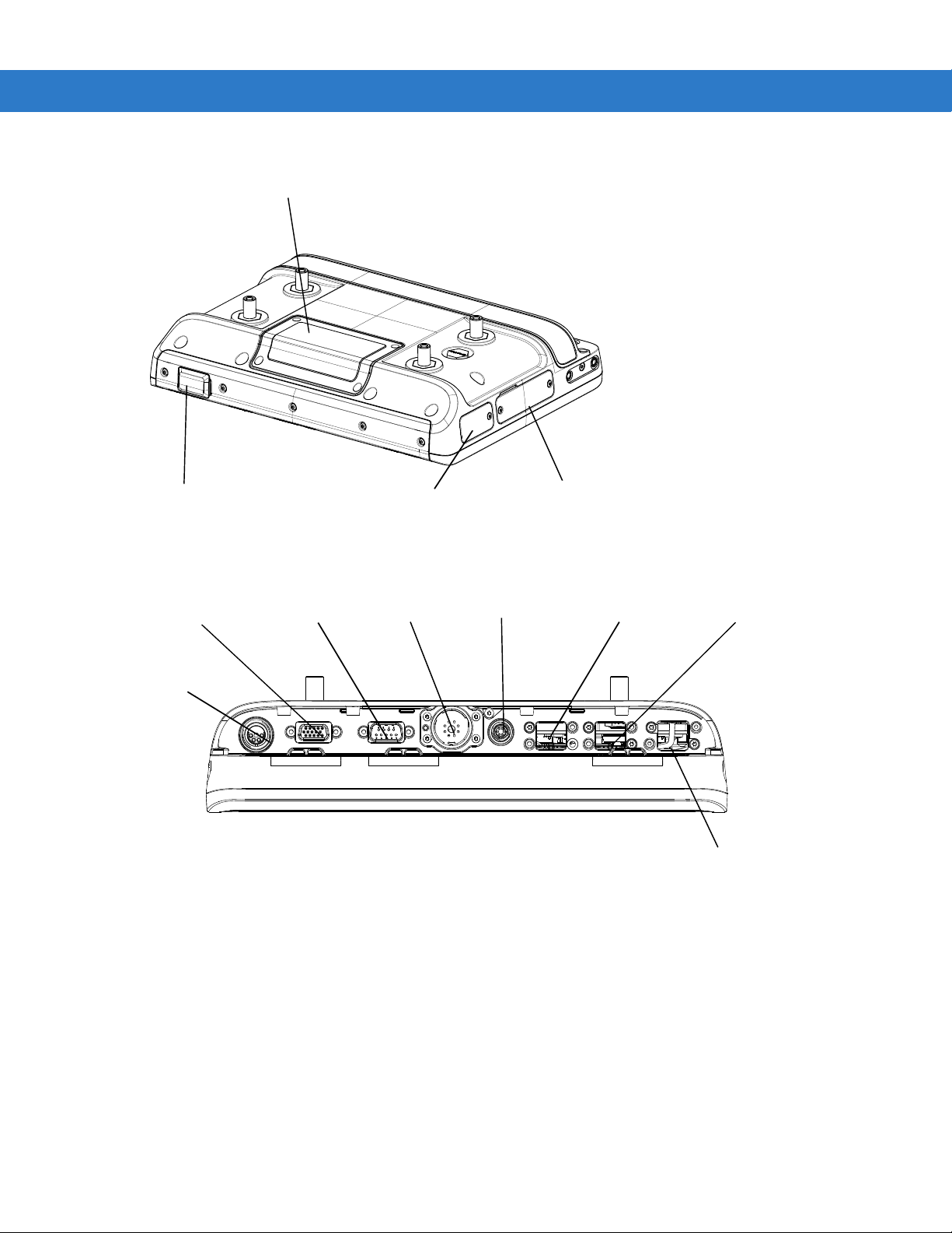
Backup Battery Door
Getting Started 1 - 3
Antenna Port for
Optional External
Antenna
Figure 1-2 VC70 Back View
COM2 + CAN-bus
Power
COM1 Port
Figure 1-3 VC70 Bottom View
Main Power
Switch
Microphone
External Speaker
Bottom Connectors
Service Door
USB 1
USB 2
Ethernet
Page 22

1 - 4 VC70 Vehicle Computer Product Reference Guide
Accessories
Table 1-2 lists the accessories available from Zebral for the VC70:
Table 1-1
Keyboards
Keyboard: QWERTY, 64-key Backlit, IP66, secured USB-A, VC70. Requires
KT-KYBDTRAY-VC70-R mounting tray
Keyboard: AZERTY, 64-key Backlit, IP66, secured USB-A, VC70. Requires
KT-KYBDTRAY-VC70-R mounting tray
Keyboard Protection Grill, QWERTY/AZERTY, VC70 KT-KYBDGRL1-VC70-R
QWERTY/AZERTY Keyboard mounting tray. Includes tilting arms, knobs and screws KT-KYBDTRAY-VC70-R
Keyboard: 21 Keys, BACKLIT, IP66 SEALED, USB, FUNC/NUM KYBD-NU-VC70-03R
Keyboard Protection Grill, Functional/Numeric, VC70 KT-KYBDGRL2-VC70-R
Function/Numeric keypad side mount bracket KT-KYBDMNT-VC70-R
VC5090 keyboard mounting and cable adapters for VC70. Used when reusing existing VC5090
keyboard
Ke yboard: 64 Keys, BACKLIT, IP66 SEALED, HT, QWERTY VC5090KYBD-02R
Ke yboard: 64 Keys, BACKLIT, IP66 SEALED, HT, AZERTY VC5090KYBD-03R
Accessories
Accessory Description Part Number
KYBD-QW-VC70-03R
KYBD-AZ-VC70-03R
KT-VC50KYBD-ADPT-R
Power supplies and power cables
External DC power supply VC70, 9-60VDC Requires 25-159551-01 fused DC power cable to
vehicle battery
AC Power supply Provides power to the VC70 from a 100-240V AC grid. Requires
25-159550-01 adapter cable. Order country specific three wire
grounded AC line cord separately.
External DC power supply
cable to vehicle battery
Cable External power supply cable to VC70 extender. 6.5 feet, VC70 25-159549-01
External power supply
cable, to existing VC5090
power cable
Power supply cable for AC
power supply
9-60V DC, 10 feet includes fuse, VC70. Required for the
PWRS-9-60VDC-R
Includes fuses, 2 feet, VC70.
(VC5090 Cable: 25-71919-03R or 25-71919-04R)
AC power supply adapter cable, 6.5 feet, VC70 25-159550-01
PWRS-9-60VDC-01R
PWRS-14000-241R
25-159551-01
25-159553-01
Page 23

Getting Started 1 - 5
Table 1-1
US AC line cord US AC line cord, grounded, three wire for power supplies
Scanner Cables
USB Cable for
DS3508-ER, LS3408-ER
scanners
RS232 Cable with TTL
Converter
DB15 to DB9 adapter DB15 to DB9 adapter, 6". Use with CBA-R49-C09ZAR for VC70
Accessories (Continued)
Accessory Description Part Number
PWRS-14000-148R, PWRS-14000-241R, PWRS-0102246H51R,
and PWRS-14000-148C. 7.5 feet long.
Associated Countries: United States Works with: MC1000, MC17,
MC55, MC65, MC70, MC75, MC75A, MC9000, MC9100, MC9500,
VC6000, WT4000, and ET1
Coiled, 12 feet, sealed USB secured connector, VC70. Required
when the DS3508-ER or LS3408-ER are connected via one of the
USB ports for HID interface. Can also be used to connect a
charge-only cradle when using the cordless DS3578-ER or
LS3578-ER.
DB9 Female Connector, 9 feet (2.8m) Coiled, Power Pin 9 with
RS232 to TTL converter. To be used with DS3508-ER or
LS3408-ER scanner. Can also be used to connect a charge-only
cradle when using the cordless DS3578-ER or LS3578-ER.
COM2 serial port scanner. Can also be used to connect other
equipment with RS232 interface when CAN bus is not needed.
23844-00-00R
25-159548-01
CBA-R49-C09ZAR
25-159547-01
Mounting
U mount for VC70 with
mounting hardware
Accessory side mount
bracket
Mounting holder
LS34x8ER/LS35x8ER
scanner
RAM bridge with
RAM-D-2461U RAM
MOUNT
RAM-D-2461U RAM
MOUNT
Audio
External speaker Zebra HSN4040A 13 Watt water-resistant loudspeaker. Requires
Used when replacing VC5090 mounted with its own U mount KT-U-MOUNT-VC70-R
Used with HMN1089B microphone or KT-SCANMNT-VC70-R
scanner mounting holder
Requires KT-ACCMNT-VC70-R Accessory side mount bracket KT-SCANMNT-VC70-R
D (2.25”) size ball with screws. Including screws to mount the
PWRS-9-60VDC-01R External DC Power Supply. Used when
replacing equipment already mounted with RAM mounts
D (2.25”) size ball with screws. Used when the
PWRS-9-60VDC-01R External DC Power Supply has to be
mounted away or when AC power supply is used.
Used when replacing equipment already mounted with RAM
mounts
25-159552-01
KT-ACCMNT-VC70-R
RAM-D-2461U-MOTO7
RAM-D-2461U-MOTO7B
HSN4040A
Push-To-Talk Hand
Microphone
GCAI connector, water resistant HMN1089B
Page 24

1 - 6 VC70 Vehicle Computer Product Reference Guide
Table 1-1
Miscellaneous
De siccant bags Set of 5 desiccant bags KT-DSCNT-VC70-05R
Screen protector Set of 5 screen protectors KT-SPRTCT-VC70-05R
Antenna
Antenna 2.4GHZ MIN, 5.9GHZ MAX.
Antenna adapter Adapter for WTS2450-RPSMA Antenna.
Roof mounted mobile
antenna
Accessories (Continued)
Accessory Description Part Number
Speaker cable adapter for HSN4040A, VC70. Required to connect
the HSN4040A external speaker
Connector-mount, multi-band, Omni. Requires the use of an
antenna adapter.
Reverse polarity SMA male reverse thread to reverse polarity SMA
female.
2.4GHZ MIN, 5.9GHZ MAX, 0DBI 8508851K46
25-159552-01
AN2030
RPSMA-RTRPSMA-05R
(Pack of five adapters)
RPSMA-RTRPSMA-10R
(Pack of 10 adapters)
Battery
VC70 battery Spare battery kit BTRY-VC70IAB00
Page 25

Chapter 2 Installation
Introduction
This chapter describes how to install the vehicle computer in a vehicle or on a desktop and connecting the vehicle
computer to a power source. There are different installation options depending on the type of vehicle. This chapter
also describes how to install the various accessories for the vehicle computer. Read all of the following instructions
before you begin.
WARNING
CAUTION
NOTE
!
The vehicle computer and bracket must be firmly secured to a surface that can support the
vehicle computer’s weight.
A competent engineer must perform the installation in a vehicle. Improper installation can damage your
vehicle and/or the VC70.
Do not install the vehicle computer in a location that will affect vehicle safety, drivability, or visibility.
All bolts and screws used for installing the VC70 are metric type with T7 to T30 TORX head.
Page 26

2 - 2 VC70 Vehicle Computer Product Reference Guide
Electrical Power Wiring
IMPORTANT
•
Establish a neat route for the cable, staying clear of moving parts or hot surfaces.
•
Fix the cable to existing cable runs inside the vehicle using cable ties, but make sure they are away from any
moving or hot surfaces.
•
When the cabling must go through a panel, use a suitable gland.
•
When fixing the conduit or cable on the outside of a vehicle, use P-Clips. Either drill and tap the hole or use a
nut and bolt to secure the clip.
•
Ensure the cable does not have tight bends. The minimum recommended radius is 63.5 mm (2.5 in.).
•
Ensure cables do not swing or chafe on the structure. This often requires using cable ties approximately
every foot, and ensuring the cables do not flex often, especially where they connect to the VC70. However, if
you must re-position the VC70 occasionally, ensure there is enough slack in the cable to accommodate
movement without putting tension on the cable.
•
DO NOT wind a cable in and out of the mesh on a cage.
•
On electric vehicles, take the power from as close to the battery as possible, but not directly from the battery
terminals, and not before any main fuse.
•
On gasoline, diesel or propane vehicles, take the power from as close to the battery terminals as possible,
and avoid using existing wiring.
•
Ensure that all fuses are as close as possible to the power source.
When replacing the forklift battery, avoid draining the internal backup battery of the VC70 by pressing
the power button on the front panel for putting the VC70 in unattended mode.
Page 27
Installation 2 - 3
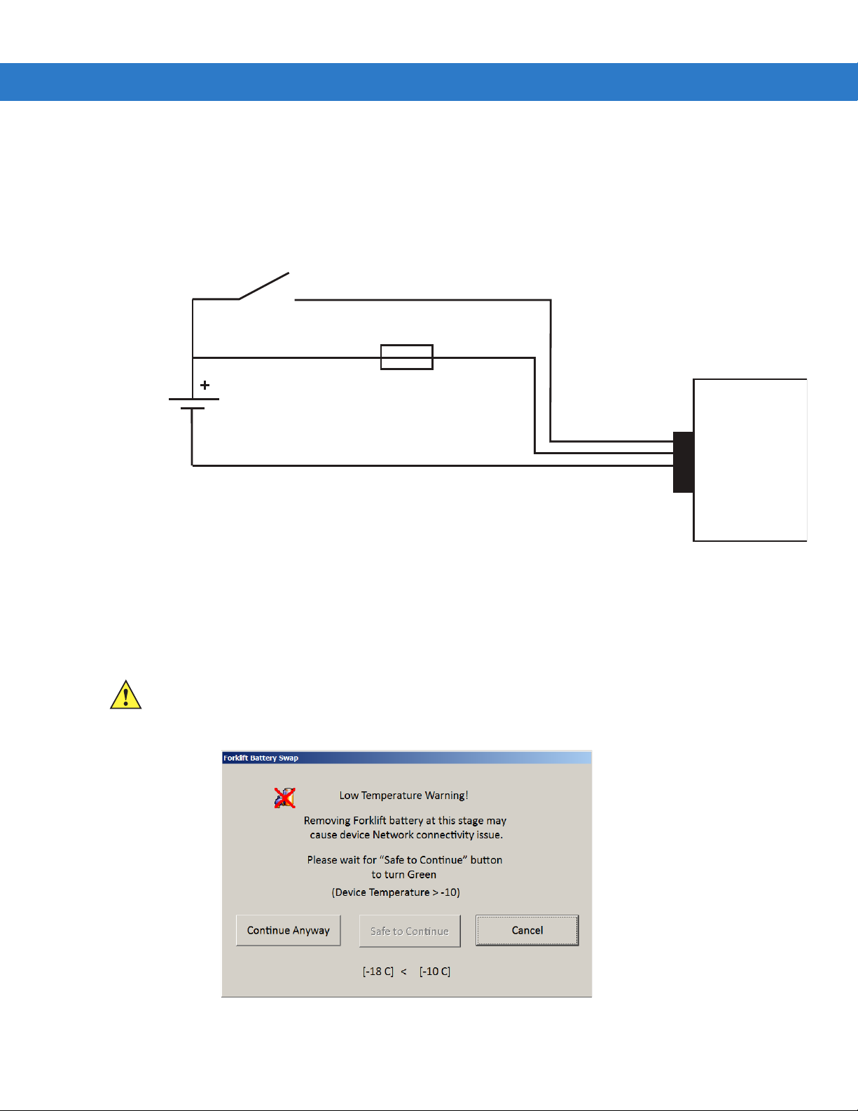
Forklifts and Trucks with 12V, 24V, 36V and 48V Batteries
•
All power wiring must use the supplied 25-159551-01 power cable.
•
One 3AB, 15A, 250V, FST BLO fuse.
•
Keep the path between the battery and the vehicle computer as short as possible and away from any part of
the ignition high tension system.
Yellow
Ignition Switch or Key Switch
15A Fuse
Red
Vehicle
Battery
Power Cable
25-159551-01
9-60V DC
Black
Important: If your vehicle is not equipped with an ignition or key switch, connect the yellow wire directly
to the positive terminal of the vehicle’s battery. Failure to comply, will disenable the VC70 operation.
Figure 2-1
Wiring Diagram
VC70
You can use your old VC5090 power cable. When employing this option, use VC5090 Bridge Cable, PN
25-159553-01. You must also replace the fuses on the red and black wires of the old cable with the new fuses
supplied with the bridge cable kit.
1. Disconnect the vehicle battery.
CAUTION
To prevent damage to the VC70, replacing the vehicle battery is forbidden when the ambient
temperature is under -10
shown on the VC70 screen and prevent the user from switching off the VC70. To replace the battery,
move to a place with temperature is above -10
°C
. Attempting to replace a battery under -10
°C
- the warning screen will disappear.
°C
will result in a warning
Figure 2-2
Forklift Battery Swap - Low Temperature Warning
Page 28

2 - 4 VC70 Vehicle Computer Product Reference Guide
2. Connect the red wire directly to the vehicle's battery positive terminal. Connect the black wire directly to the
vehicle's battery negative terminal.
The vehicle computer contains an Ignition Sense feature that detects when the ignition switch or key
NOTE
switch is turned off and shuts the vehicle computer down after a preprogrammed timeout. This feature
allows the operator to use the vehicle computer for a predetermined time period after the ignition switch or
key switch is turned off, then shuts the vehicle computer down automatically to prevent over-discharge of
the forklift battery. The timeout period is adjustable by the user (see Ignition Sensing on page 2-5 for
setting the timeout value). When the vehicle computer enters low power mode using the Ignition Sense
feature, current draw from the vehicle battery is reduced to less than 15mA and the vehicle computer
consumes current from it's internal battery. This feature provides the automatic shutoff functionality of an
external relay, without requiring an actual relay and has the added benefit of allowing the user to work for
a preset time period before shutting down.
NOTE
For power drain of the forklift battery under the various power conditions, refer to Power Status on page
3-22.
NOTE
See the vehicle Owner's Manual for specific wiring information.
3. Connect the yellow wire to the vehicle's ignition or key switch if such is used. If you do not plan on using the
Ignition Sense feature, connect the yellow wire directly to the vehicle’s battery positive terminal.
4. Ensure the wiring connections created are sufficiently insulated from each other.
5. Re-connect the vehicle battery.
6. Connect the power cable connector into the vehicle computer's Power port. Align the keyway on the power
connector with the notch on the vehicle computer’s power port.
7. If the power supply is mounted remotely from the VC70, use 25-159549-01 extender cable to connect
between the power supply and the VC70.
8. Secure the power cables on both sides of the power supply with cable ties as close as possible to the
connectors.
The VC70 display can be blanked when the vehicle is moving to eliminate driver distraction for safety
considerations (see Screen locking feature on page 11-6).
To recover from display lock:
1. Press and hold on touch screen (more than 1 second).
2. Remove your finger from the screen to resume operation.
Page 29
Installation 2 - 5
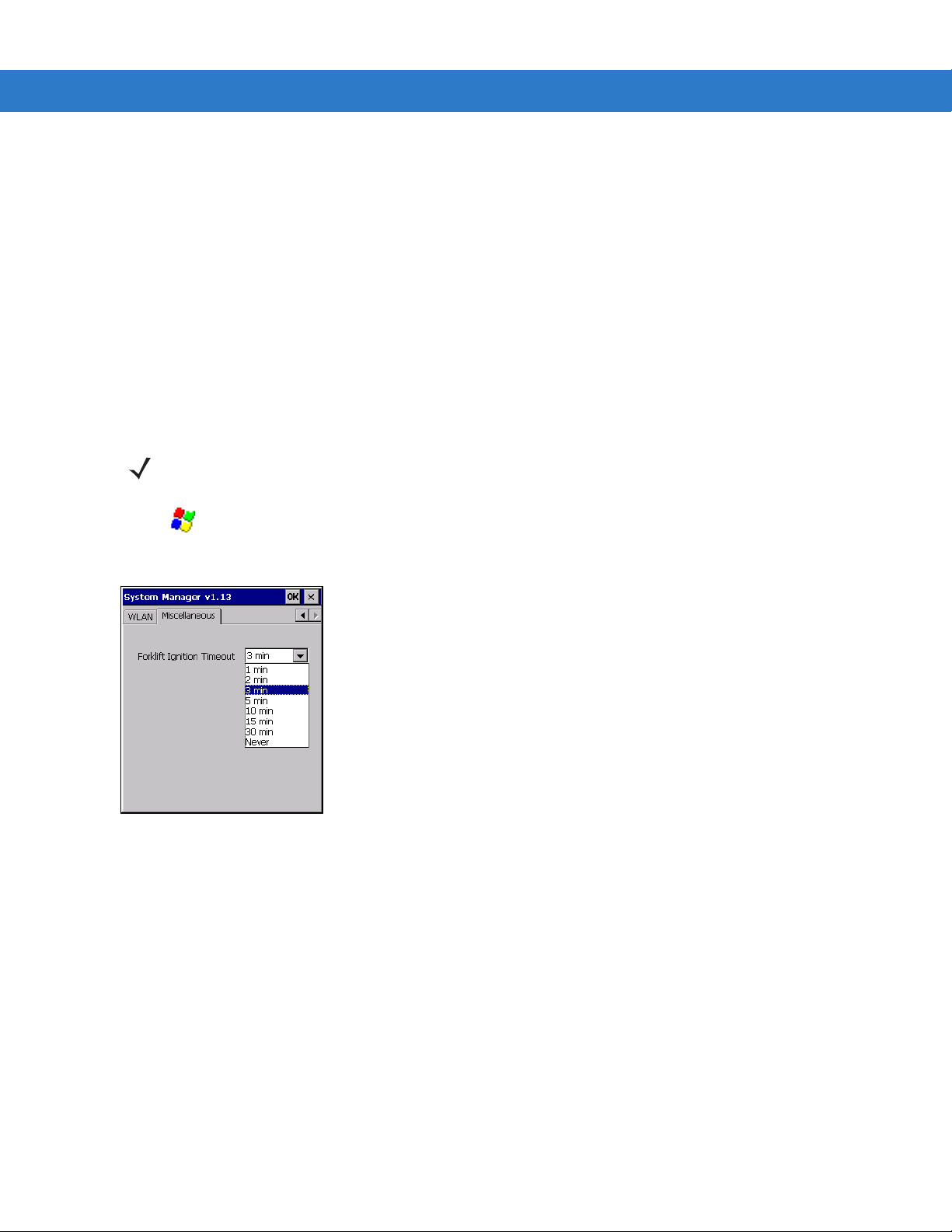
Ignition Sensing
The vehicle computer contains an Ignition Sense feature that detects when the ignition switch or key switch is
turned off and shuts the vehicle computer down after a preprogrammed timeout. This feature allows the operator to
use the vehicle computer for a predetermined time period after the ignition switch or key switch is turned off, then
shuts the vehicle computer down automatically to prevent over-discharge of the forklift battery. The timeout period
is adjustable by the user. When the vehicle computer enters low power mode using the Ignition Sense feature,
current draw from the vehicle battery is reduced to less than 15mA and the vehicle computer consumes current
from it's internal battery. This feature provides the automatic shutoff functionality of an external relay, without
requiring an actual relay and has the added benefit of allowing the user to work for a preset time period before
shutting down.
The power cable must be connected to the ignition switch or key switch. See Forklifts and Trucks with 12V, 24V,
36V and 48V Batteries on page 2-3 for information on connecting the power cable to enable the Ignition Sense
feature.
NOTE
These settings are not persistent across a cold boot.
1. Tap > Settings > Control Panel > VC70 System Manager icon. The System Manager window displays.
2. Select the Miscellaneous tab.
Figure 2-3
3. In the Forklift Ignition Timeout drop-down list, select the amount of time before the vehicle computer shuts
Miscellaneous Tab Window
down after the ignition switch or key switch is turned off.
4. Tap OK.
Page 30

2 - 6 VC70 Vehicle Computer Product Reference Guide
VC70 Power States
NOTE
Refer to Power Status on page 3-22 for description of the various power states.
Table 2-1 describes the power drain of the forklift battery under various power conditions.
Table 2-1
Power
State
Power On Connected On On Not Pressed
Low
Power
VC70 Power States
Forklift
battery
Connected On On
Connected
Not
Connected
Ignition
Off after
inactivity
timer expires
(programma
ble, 3
minutes
default)
Don't Care On Pressed
Power
Switch
On Not Pressed
Power Key
Pressed
(from Power
On State)
Power State
Description
System on with full
functionality.
System on with
display, touch
screen and audio
off. (see Waking
the Vehicle
Computer on page
3-23)
Reduced power
consumption mod,
external power
turned off - 15mA
current drain from
forklift battery.
System powered
from internal
battery. When the
capacity of the
internal battery is
reduced to 50%,
the device goes to
Critical Suspend
state.
Power drain from
forklift battery
Typical when internal
battery is not charging
- 15W.
Typical during internal
battery charging 22W.
Maximum during
operation - 100W.
No internal battery
charging - 7.5W.
Internal battery
charging - 15W
External power supply
idle current - 0.2W
Critical
Suspend
Don't Care Don't Care Off Don't Care
System off. Unit in
backup mode up to
72 hours.
Unit kept alive by
internal backup
battery.
External power supply
idle current - 0.2W
Page 31

Installing the VC70 on a Cart, a Wall, or a Desktop
To mount the vehicle computer on a cart, a wall, or a desktop:
•
Install the U-mount to the desktop.
•
Connect the vehicle computer to the AC power supply.
NOTE
For AC power supply and cables, refer to Accessories on page 1-4.
Mounting the Bracket on a Desktop
Installation 2 - 7
CAUTION
NOTE
Lock Washers
Flat Washers
If mounting to a thin surface such as drywall or plywood, a reinforcing plate is required.
The VC70 ships with four No. 8 Allen head screws (M10x50mm) for securing the mounting bracket. If the
supplied cap screws are not long enough, use M10 - X stainless steel Allen head screws where X represents
the length in millimeters of the required screws.
Allen Head Screws
U-mount
Flat Washers
Mounting Surface
Lock Washers
Nuts
Figure 2-4
Mounting on a Desktop
Page 32

2 - 8 VC70 Vehicle Computer Product Reference Guide
Connecting the Vehicle Computer to AC Power
NOTE
Use only a Zebra-approved power supply, output rated 12 VDC and minimum 9A (part number
50-14000--241R). The power supply is certified to EN60950 with SELV outputs.
To provide power from an AC source:
1. Insert the AC line cord into the AC connector on the universal power supply.
AC Line Cord
Power Port
Figure 2-5
2. Plug the other end of the AC power cable into a wall outlet.
3. Insert the DC power cable into the DC connector on the universal power supply.
4. Plug the other end of the cable into the vehicle computer’s Power port.
Connecting AC power
NOTE
For power supply and cables, refer to Accessories on page 1-4.
Universal Power Supply
(PWRS-14000-24
1R)
DC Power Cable
(25-159550-01)
Page 33

Installing the DC Power Supply (PSU) on the VC70
NOTE
Follow this procedure when using the U-mount. The PSU fastening screws are supplied with the U-mount kit.
5. Attach the PSU to the back of the vehicle computer.
6. Screw the four M5x14mm screws into the PSU mounting holes and tighten. Torque the screws 20 ± 10%
kgf-cm (17 ± 10% lbs-in).
Installation 2 - 9
Figure 2-6
NOTE
Vehicle Computer
PSU
Fastening Screws
Installing the PSU
Whenever the PSU needs to be mounted remotely, refer to Installing the PSU on page 2-9 to prepare the
mounting solution. You need to also use an extender cable PN 25-159549-01 to connect the PSU to the
vehicle computer. For power supply and cables, refer to Accessories on page 1-4.
Page 34

2 - 10 VC70 Vehicle Computer Product Reference Guide
Measurements are given in
millimeters.
Figure 2-7
PSU Installation Template
Installing a Micro SD Card
A micro SD (Secure Digital) card provides secondary non-volatile storage. The card holder is located on the right
side of the VC70 under the Service door.
To install the micro SD card:
1. Remove the two T8 TORX screws securing the Service door.
Service Door
Micro SD Card
Memory Card
Slot
Figure 2-8
2. Push the memory card, with the contacts up, into the card slot until it locks.
3. Replace the Service door and secure using two T8 TORX screws.
Install Memory Card
CAUTION
Ensure to torque the screws to seal the device properly. Otherwise, sealing can be compromised.
Torque the Torx head screws to 4.0 + 10% kgf-cm (3.5 ± 10% lbs-in).
Page 35

RAM Mount Installation
Installation 2 - 11
CAUTION
NOTE
If mounting to a thin surface such as drywall or plywood, a reinforcing plate is required.
For RAM Mounts, refer to Accessories on page 1-4.
The RAM Double Socket Arm Mount allows the VC70 to be easily adjusted to most comfortable location. A single
Adjustment Knob enables simultaneous adjustment of both upper and lower ball joints. The mount affixes to the
forklift cage or other strong surface by the supplied hardware kit and bolts provided by the customer (Search for
VC70 on http://www.rammount.com
).
To install the RAM Mount:
1. If Installed, remove the two threded booshings from within the supporting bracket.
Supporting Bracket
Threded Booshings
Torx 8 screw Locations
Figure 2-9
2. Place the Bridge Mount onto the Supporting Bracket.
3. Use two M12x40mm hex head bolts into mounting holes and tighten. Torque the hex head screws to 350 ±
Removing the Threded Booshings from within the Supporting Bracket
10% kgf-cm (300 ± 10% lbs-in)
4. Use four bolts, nuts, lock washers and flat washers to install the Ball Base to the Bridge Mount. Torque the
bolts to 91.7 kgf-cm ± 10% (79.6 ± 10% lbs-in).
5. Use four bolts, nuts, lock washers and flat washers to install the Ball Base to the forklift surface. Torque the
bolts to 91.7 kgf-cm ± 10% (79.6 ± 10% lbs-in).
Page 36

2 - 12 VC70 Vehicle Computer Product Reference Guide
6. Install the Double Socket Arm Mount. Adjust the VC70 to the best view position and fasten the Adjustment
Knob.
Bushing
Lock Washers
M12x40mm Hex Hhead Bolt
Nut
Flat Washers
Lock Washers
M6 X 22 Bolt
Bridge Mount
Ball Plate
Nut
Lock Washer
Flat Washers
M6 X 22 Bolt
Adjustment Knob
Double Socket
Arm Mount
Ball Plate
Figure 2-10
RAM Double Socket Arm Mount
Page 37

U-Mount Installation
Installation 2 - 13
The U Mount (P/N:
KT-U-MOUNT-VC70-R)
for is used for replacing a mounted VC5090 with the VC70.
To install the U-mount:
1. Position the friction pads in the friction pad mounting area.
2. Position the U-mount over the mounting holes.
3. Place lock and flat washers onto cap screws.
4. Screw the M12x40mm hex head screws into mounting holes and tighten. Torque the hex head screws to 350 ±
10% kgf-cm (300 ± 10% lbs-in).
U -Mount
Lock Washer
Hex Head Screw
Supporting Bracket
Flat Washer
Friction Pad
Friction Pad Mounting Area
Figure 2-11
U-mount Installation
To remove the U-mount:
1. Release and remove the two hex head screws, lock washers, flat washers and friction pad.
2. Remove the U-Munt from the supporting bracket.
Remove the two Torx 8 screws that secure the two threded booshings.
Page 38

2 - 14 VC70 Vehicle Computer Product Reference Guide
Installing the VC70 on a Forklift
CAUTION
Follow the instructions below to properly install the VC70 on a forklift.
•
Determine the best location for mounting the vehicle computer taking into consideration the driver’s field of
view and ease of accessing the vehicle computer.
•
Install the appropriate mounting hardware.The VC70 ships with four No. 8 Allen head screws (M10x50mm)
for securing the mounting bracket. If the supplied cap screws are not long enough, use M10 - X stainless
steel Allen head screws where X represents the length in millimeters of the required screws.
•
Connect the vehicle computer to the vehicle’s wiring system.
A competent engineer must perform the installation in a vehicle. Improper installation can injure the
operator and damage your vehicle and/or the VC70.
Positioning the Vehicle Computer
•
Determine the best position for the vehicle computer and all the associated components. If a similar vehicle
computer was previously installed, check to see if the position it used is suitable for the VC70.
•
Test the installation for at least 30 minutes before installing on another vehicle. Record all details:
• Check that the position of the vehicle computer does not obstruct vehicle controls.
Figure 2-12
View Obstruction
• Check that the vehicle computer does not obstruct the driver's view.
• Check the position of the vehicle computer for user comfort over long periods.
• Check positioning to avoid extreme wrist angles that may cause injury.
Page 39

Installation 2 - 15
Figure 2-13
Figure 2-14
Avoid Extreme Wrist Angles
Optimum Wrist Positions
Page 40

2 - 16 VC70 Vehicle Computer Product Reference Guide
Mounting the Vehicle Computer
U-Mount Installation Template
Drill Holes: 10.1 mm ± 0.1 mm
0.43 ± 0.004 in.
160.00 ± 0.20 mm
6.299 ± 0.008 in.
25.40 ± 0.10 mm
1.00 ±0.004 in.
Figure 2-15
Mounting Template
Page 41

Important Fixing Information
Installation 2 - 17
CAUTION
•
Mounting surface must be flat and stiff and it must extend evenly for the entire length of the mounting bracket
Any modification to supplied mounting bracket could cause failure of the unit and/or mountings.
surface.
•
All four mounting holes must be used.
•
All nuts and bolts must be checked periodically and tightened if required.
•
When installing the vehicle computer, care must be taken to ensure that the mounting bracket footprint is fully
supported. Additional plates may be required to achieve this.
•
Do not mount the vehicle computer with the mounting bracket perpendicular to a wall.
Mounting onto an Over-Head Cross-Beam Example
The diagram below illustrates a typical installation where the vehicle computer is mounted onto a cross-beam.
Lock Washers
Nuts
Flat Washers
Flat Washers
Vehicle Cross-Beam
Allen Head Screws
Figure 2-16
Lock Washers
Mounting the VC70 onto an Over-Head Cross-Beam Example
U-mount
Mounting onto an Over-Head Cage Example
The diagrams below illustrates a typical installation where the vehicle computer is mounted on an overhead cage.
A customer supplied mounting plate must be used that can withstand the weight of the vehicle computer under
vibration and shock. The plate must be made of stainless steel or hardened steel with the following dimensions: 3.0
in. (76.0 mm) wide, 8.66 in. (220.0 mm) long and 0.2 in. (5.0 mm) thick. The plate must be secured with hardware
or to the underside of the cage by welding.
Page 42

2 - 18 VC70 Vehicle Computer Product Reference Guide
Lock Washers
Flat Washers
Flat Washers
Lock Washers
Allen Head Screws
Nuts
Customer Supplied
Mounting Plate
U-mount
Figure 2-17
Mounting on Flat Overhead Beams
Page 43

Installation 2 - 19
Nuts
Allen Head Screws
Figure 2-18
Lock Washers
Flat Washers
Flat Washers
Lock Washers
Mounting on Transverse Overhead Beams
Mounting on a Dashboard or Horizontal Surface Example
Customer Supplied
Mounting Plate
Welded to Beams
U-mount
The diagram below illustrates a typical installation where the vehicle computer is mounted on a dashboard or
horizontal flat surface.
NOTE
If mounting to a thin surface, a reinforcing plate maybe required.
Allen Head Screws
Lock Washers
Flat Washers
U-mount
Flat Washers
Lock Washers
Nuts
Mounting Surface
Figure 2-19
Mounting on a Vehicle Dashboard
Page 44

2 - 20 VC70 Vehicle Computer Product Reference Guide
Installing the Optional QWERTY/AZERTY Keyboard
The keyboard kit contains the following items:
•
Keyboard
•
Right and left mounting arms
•
Four torx head screws with flat and lock washers
•
Six screws with captive flat and lock washers (for keyboard fastening)
•
Two locking knobs, two flat washers and two lock washers.
1. Position the keyboard on the tray and fasten six M4x10mm screws.
6 Screws with
captive washers
Tray
Keyboard
Figure 2-20
2. Attach the left and right mounting arms to both sides of the VC70, using the M5x14mm Torx head screws with
flat and lock washers. Only tighten the cap screws three turns.
Attaching the Keyboard to the Tray
NOTE
For optional QWERTY/AZERTY keyboards, refer to Accessories on page 1-4.
Page 45

Left Mounting
Arm
Torx Head
Screws with Flat
and Lock
Washers
Flat Washer
Lock Washer
Locking
Knob
Installation 2 - 21
Figure 2-21
1. Insert the keyboard locking knobs through the washers and brackets and screw into the keyboard tray. Tighten
Attaching the Brackets to the VC70
fully to lock into place.
2. Torque the mounting arms torx head screws to 40 + 10% kgf-cm (35 + 10% lbs-in).
3. To adjust keyboard tray position, loosen the right and left locking knobs two full turns and rotate the keyboard
tray to the desired position. The keyboard tray snaps into possible positions as it is rotated.
Figure 2-22
Adjusting the Keyboard Tray Position
4. Tighten the keyboard tray locking knobs to secure the tray in position.
5. Plug the keyboard cable into one of the USB connectors and carefully screw the locking screws using a flat
head screw driver.
Page 46

2 - 22 VC70 Vehicle Computer Product Reference Guide
USB Connector
Figure 2-23
USB Connectors
Installing the Optional VC5090 Keyboard on the VC70
You can install the VC5090 keyboard on the VC70 using the keyboard adapter kit (PN KT-VC50KYBD-ADPT-R).
The kit contains the following items:
•
Two spacers with screws and washers
•
Adapter cable
NOTE
When using the VC5090 keyboards, the integrated keyboard heater is not supported.
For optional VC5090 keyboards, refer to Accessories on page 1-4.
1. Attach the keyboard spacers to both sides of the VC70 using 2 M5x14mm torx head screws with captive
washers for each spacer. Tork the screws to 20 + 5% kgf-cm (17 + 5% lbs-in).
Left Hand
Bracket
VC70 Spacer
Torx Head
Screws
VC70
Locking Knob with Flat and
Lock Washers
Figure 2-24
Cap
Screws
VC5090 Keyboard
Installing the VC5090 Keyboard on the VC70
Page 47

Installation 2 - 23
2. Attach the VC5090 keyboard brackets (part of the VC5090 keyboard assembly) to both sides of the VC70,
using the cap screws with captive washers. Only tighten the cap screws three turns.
3. Insert the keyboard locking knobs through the washers and brackets and screw into the keyboard. Tighten fully
to lock into place.
4. Torque the bracket cap screws to 230 kgf-cm (200 lbs-in).
5. Connect the VC5090 keyboard cable to the supplied adapter cable.
Connect the VC5090 Keyboard Cable here
Connect to a VC70 USB Connector
Figure 2-25
6. Connect the USB connector of the adapter cable into one of the VC70 USB connectors and carefully screw the
VC5090 Adapter Cable
locking screws using a flat head screw driver.
Installing a Numeric Keyboard
The Numeric keyboard is installed using the following items:
•
numeric keyboard mount with all required screws for attaching the keyboard to the mount and the mount to
the vehicle computer
1. Attach the numeric keyboard to the mount, using six M4x10mm torx head screws with captive washers.
2. Torque the numeric keyboard Torx head screws to 8 + 10% kgf-cm (7 + 10% lbs-in).
NOTE
The Numeric Keyboard can be installed on both sides of the Numeric Keyboard Mount.
For optional numeric keyboards, refer to Accessories on page 1-4.
Page 48

2 - 24 VC70 Vehicle Computer Product Reference Guide
Numeric Keyboard
Figure 2-26
3. Attach the numeric keyboard mount to the VC70, using four M5x14mm torx head screws with captive
Installing the Numeric Keyboard on the Mount
Numeric Keyboard Mount
6 Torx Head Screws with captive washers
washers.Tighten the screws.
4. Torque the numeric keyboard torx head screws to 20 + 10% kgf-cm (17 + 10% lbs-in).
Numeric Keyboard
Numeric Keyboard Connector
4 Torx Head Screws with
Captive Washers
Figure 2-27
5. Connect the numeric keyboard to a free USB connector. Fasten the screws using a flat head screw driver.
Installing the Mount on the VC70
Page 49

Keyboard Protection Grill Installation
To protect the VC70 keyboard, it is recommended to install a protection grill. Different grills should be used with the
QWERTY/AZERTY or Numeric keyboard.
Each grill kit includes the following items:
•
Two Securing Strings
•
Keyboard Protection Grill
To install the grill:
1. Place the cover onto to the VC70 keyboard.
2. Use the two Securing Strings to attach the Protection Grill to the keyboard.
Installation 2 - 25
Numeric Keyboard Protection Grill
Figure 2-28
Keyboard Covers
NOTE
For Keyboard Protection Grills, refer to Accessories on page 1-4.
QWERTY/AZERTY Keyboard Protection Grill
Securing
Strings
Page 50

2 - 26 VC70 Vehicle Computer Product Reference Guide
Installing the Scanner Mount
The Scanner mount kit contains the following items:
•
Side accessory mount (PN KT-ACCMNT-VC70-R) with two screws, two captive lock washers and flat
washers
•
Scanner mount (PN KT-SCANMNT-VC70-R) with four screws, four captive lock washers and flat washers
NOTE
For scanner mounts information, refer to Accessories on page 1-4.
1. Attach the scanner mount to the side accessory mount, using four M4x10mm screws with captive flat and lock
washers. Torque the screws to 8 + 10% kgf-cm (7 + 10% lbs-in).
2. Attach the side accessory mount to the VC70, using two M5x14mm screws with captive flat and lock
washers.Tork the screws to 20 + 10% kgf-cm (17 + 10% lbs-in).
Side Accessory
Mount
Screws
Scanner Mount
Figure 2-29
Screws
Installing the Scanner Bracket
Page 51

Installing a Stubby Antenna
Installation 2 - 27
IMPORTANT
The stubby antenna must only be used with BSP software version 34.11 and above.
To install an external antenna: stubby antenna
1. Lift the Antenna Connector cap on top of the vehicle computer.
2. Screw the Antenna adapter onto the Antenna Connector. Torque to 5 ± 0.5 kgf/cm (4.3 ± 0.4 in-lbs).
3. Screw the Antenna onto the Antenna adapter.
4. Fasten the Ring at the base of the Antenna to cover as much threads as possible.
Stubby Antenna (AN2030)
3
Antenna
Connector Cap
4
1
Ring
Antenna adapter
2
Figure 2-30
Antenna Connector
Antenna Installation Example
Page 52

2 - 28 VC70 Vehicle Computer Product Reference Guide
Installing the External Roof-mounted Antenna
WARNING
!
The antenna must be installed in a location that will ensure a distance of at least 8” (20cm)
between the antenna and any bystander.
Sharkfin Antenna
12 feet (144+/-4") Cable
Figure 2-31
Sharkfin Antenna
NOTE
Do not use VC5090 antennas.
For general antenna installation instructions refer to the Installation Guide supplied with the antenna.
IMPORTANT
1. Tap > Settings > Control Panel > System Manager icon. The System Manager window displays.
Figure 2-32
2. Tap the External Devices tab.
3. Tap the External Antenna radio button.
4. Tap OK.
If not installed on a metal roof, the antenna must be installed in the middle of a flat metal surface (minimum
size 2.56” (65 mm)x2.56” (65 mm)).
RF Settings Tab Window
Page 53

Connecting Accessories
Connect an optional scanner, ActiveSync serial cable, or USB device (such as a keyboard or mouse) using the
appropriate port on the bottom of the VC70.
You should use either COM1 port for serial ActiveSync or the Micro USB (Micro USB On the Go) port for USB
ActiveSync.
A standard USB keyboard or mouse can be connected to the USB A connector (Host).
Installation 2 - 29
COM2 + CAN Port
DB15 Female
Connector
Power
Connector
Figure 2-33
Connection Ports
COM1 Port
DB9 Male
Connector
Microphone
Connector
External Speaker
Connector
USB 1
Connector
Connecting an External Speaker to the Vehicle Computer
It may be necessary to install an external speaker in noisy environments. Use a Zebra HSN4040 15 Watt
water-resistant loudspeaker and connect it to the VC70 External Speaker connector using the adapter cable (PN
25-159552-01).
USB 2
Connector
Ethernet
Connector
NOTE
When connecting the adapter cable, the audio is automatically routed to the external speaker. If the external
speaker is not connected, you will not be able to hear any audio.
NOTE
For external speaker, cable and Push-To-Talk (PTT) hand microphone, refer to Accessories on page 1-4.
Installing an External Microphone Mount
The External Microphone mount consists of the following two kits:
•
microphone holder with two screws and captive washers
•
side mount with two screws and captive washers
1. Attach the microphone holder to the side mount, using two M4x12mm screws with captive washers. Torque the
screws to 8 + 10% kgf-cm (7 + 10% lbs-in).
Page 54

2 - 30 VC70 Vehicle Computer Product Reference Guide
2. Attach the side mount to the VC70, using two M5x14mm screws with captive washers.Tork the screws to 20 +
10% kgf-cm (17 + 10% lbs-in).
Screws with
Screws with
Captive
Washers
Side Mount
Captive
Washers
Microphone Holder
Figure 2-34
Installing the External Microphone Mount
Page 55

Chapter 3 Operating the VC70
Introduction
This chapter explains the buttons, status icons and controls on the VC70 and provides basic instructions for using
the VC70, including powering on and resetting. It also included instructions for entering and capturing data.
Control Panel Applications
NOTE
Some of the scanner parameters accessible through the Control Panel may not be relevant to all scanners
used with the VC70.
For a complete list of scanner setting configured by using API, refer to EMDK documentation. Alternatively,
use the configuration bar codes provided with each scanner documentation.
Table 3-1 lists the available applications on the VC70 Control Panel.
From the VC70 desktop, tap
Table 3-1
List of Control Panel Applications
Icon Description Icon Description
Backlight - Set the display backlight
time-out and adjust brightness. Refer to the
Microsoft Applications for Embedded
Version 7.00 User Guide for more
information. Refer to
Brightness on page 3-12
DataWedge - Enable data capture using a
connected Scanner.
Connection on page 4-1
Dialing - Set dialing properties. Display - Set the background and
> Settings > Control Panel.
Adjusting the
.
DataWedge Scanner
Certificates - See information about
certificates installed on the VC70.
Date/Time - Set the VC70 clock to the
date, time and time zone of your
location.
appearance of the VC70 desktop.
Page 56

3 - 2 VC70 Vehicle Computer Product Reference Guide
Icon Description Icon Description
Error Reporting - Report software errors to
Microsoft.
Internet Options - Connect the VC70 to the
Internet using the VC70 data connection.
Keyboard - Set the repeat rate for the
keyboard.
Mouse - Set double-click sensitivity for
tapping on the screen.
Owner - Enter personal information on the
VC70. Refer to the Microsoft Applications
for Windows Embedded Version 7.00 User
Guide for more information.
PC Connection - Enable or disable the
USB connectivity to a personal Computer.
Input Panel - Select the type of
keyboard to use. See
Keyboard on page 3-6
IST Settings - Set the appropriate
setting for configuring the VC70
Interactive Sensor Technology.
MotoBTUI - Enable Bluetooth radio and
other Bluetooth functionality.
Network and Dial-up Communication Set up one or more types of modem
connections for the VC70, such as
Ethernet so that the VC70 can connect
to the Internet or a local area network.
Password - Set a password for the
VC70.
Power - Check backup battery power
and set time-out and wakeup of the
VC70. Set and monitor all power related
activities. See
3-22
.
Power Status on page
Using the
.
Programmable Keys - Configure the
operation mode of the P1, P2, P3 and P4
keys on the front panel of the VC70. See
Programmable (“P”) Keys on page 3-6
Regional Settings - Set the regional
configuration to use, including the format for
displaying numbers, currency, date, and
time on the VC70.
Screen Resolution - Set SVGA or XGA
screen mode.
.
Reg Archive - Set persistence memory
to software configurations. See
Persistence on page 3-20
Remove Programs - Remove programs
installed on the VC70.
Stylus - Perform Screen Calibration.
See
Controlling the Display on page
3-25
.
Boot
.
Page 57

Operating the VC70 3 - 3
Icon Description Icon Description
System - Displays the VC70 software and
hardware information. Refer to the Microsoft
Applications for Windows Embedded
Version 7.00 User Guide for more
information.
System Manager - Enables or disables port
connection, desiccant warning and other
miscellaneous operations.
Volume & Sound - Enable sounds for
events, notifications and more. Set the type
of notification for different events. See
Adjusting the Volume on page 3-13
.
System Info - View hardware
information of VC70 and internal
components.
USBConfig - Set USB port and client
mode configuration.
Page 58

3 - 4 VC70 Vehicle Computer Product Reference Guide
Quick Access Panel
The Quick Access Panel contains buttons and LEDs to control the operation of the vehicle computer.
Ambient Light Sensor
+, P1 Button
-, P2 Button
Keyboard, P3 Button
Speaker, P4 Button
Brightness Button
Function LED
Power Button
Charging LED
COMM LED
Figure 3-1
VC70 Quick Access Panel
Power Button
Press the Power button to place the vehicle computer into low power mode. When in low power, press the Power
button to resume normal operation.
Charging LED
Table 3-2 lists the states of the charging LED.
Table 3-2
Charging LED Indications
LED State Indication
Off Backup battery charging is not available.
Solid Amber Backup battery is fully charged (backup battery only available).
Blinking Amber Backup battery is not full (backup battery only available).
Slow Blinking Amber Backup battery is low (backup battery only available).
Page 59

Operating the VC70 3 - 5
Table 3-2
Charging LED Indications
LED State Indication
Solid Green Backup battery is fully charged (both external power and backup
battery available).
Blinking Green Backup battery charging in progress (both external power and
backup battery available).
Slow Blinking Green Backup battery is low (both external power and backup battery
available).
Solid Red Backup battery not available (external power only available).
COMM LED
The COMM LED blinks to indicate WLAN radio activity. Table 3-3 lists the states of the COMM LED. By default, the
COMM LED is enabled. To disable the COMM LED:
NOTE
These settings are not persistent across a cold boot.
1. Tap My Device icon > Control Panel icon > System Manager icon. The System Manager window displays.
Figure 3-2
2. Tap the Enable Comm Led check box.
3. Tap OK.
Table 3-3
External Devices Tab Window
COMM LED Indications
LED State Indication
Solid Green Excellent, very good or good RSSI signal strength.
Slow Blinking Green (once every 2
Poor RSSI signal strength.
seconds)
Off
WLAN is OFF or not connected – no RSSI signal.
Page 60

Page 61

Operating the VC70 3 - 7
Figure 3-3
NOTE
Figure 3-4
Figure 3-5
Soft Input Panel Pop-up Menu.
SIP will display the last keyboard type that was used.
Enlarge Keyboard
Button
Reduce Keyboard
Button
Alpha-Numeric Key
Toggle Button
Numeric Key
Toggle Button
QWERTY VC70 Soft Input Panel Keyboards - Normal Size
Enlarge Keyboard
Button
Reduce Keyboard
Button
Alpha-Numeric Key
Toggle Button
Figure 3-6
Numeric Key
Toggle Button
AZERTY VC70 Soft Input Panel Keyboards - Normal Size
Page 62

3 - 8 VC70 Vehicle Computer Product Reference Guide
Numeric Key
Toggle Button
Figure 3-7
XAMLIM Soft Input Panel Keyboard
Tap the Enlarge or Reduce Keyboard button to scale the keyboard. The three sizes are small, normal and large
with normal being the default size.
To hide or show the numeric keys tap the
Figure 3-8
Keyboard with Numeric Key Hidden
To only display the numeric keys tap the
Alpha-Numeric Toggle button.
Numeric Key Toggle button.
Toggles the Numeric
Keys into F11-F20 keys.
Toggles the Numeric
Keys into F1-F10 keys.
Figure 3-9
The
FUNC key is pressed again.
Numeric Only Keys
FUNC key, when depressed, displays a second layer of characters. The second layer stays visible until the
Page 63

Operating the VC70 3 - 9
Figure 3-10
Figure 3-11
SHIFT key, when depressed, displays the shifted alpha characters on the keyboard. The shifted letters remain
The
until the
QWERTY FUNC Keys
AZERTY FUNC Keys
SHIFT key is pressed again.
Figure 3-12
Figure 3-13
QWERTY Shifted Keys
AZERTY Shifted Keys
Page 64

3 - 10 VC70 Vehicle Computer Product Reference Guide
Keyboard Functionality
Optional Numeric, QWERTY and AZERTY keyboards can be used with the vehicle computer. Refer to Figure 3-14,
Figure 3-15, Figure 3-16 and Table 3-5 for a description of the keys.
Table 3-5 describes the general functions of the keyboard.
Figure 3-14
Figure 3-15
VC70 Numeric Keyboard
VC70 QWERTY Keyboard
Page 65

Operating the VC70 3 - 11
Figure 3-16
Table 3-5
VC70 AZERTY Keyboard
Key Descriptions
Key Description
SHIFT Press the
characters or a FUNC key to perform a function.
Pressing
indicate that the next key press is 'Shifted’. Pressing SHIFT twice will result in fast
blinking indicating that this key is locked.
CTRL Press the
combination to access the menu.
Pressing
that the next key press is 'Controlled'. Pressing CTRL twice will result in fast blinking
indicating that this key is locked.
ALT Press the
Pressing ALT once will result in the backlight of these key to start blinking to indicate
that the next key press is 'Altered'. Pressing
indicating that this key is locked.
SHIFT key followed by an alpha key to create uppercase alphabetic
SHIFT once will result in the backlight of these key to start blinking to
CTRL key to activate alternate control functions. Use CTRL - ESC key
CTRL once will result in the backlight of these key to start blinking to indicate
ALT key to activate alternate keyboard functions.
ALT twice will result in fast blinking
Page 66

3 - 12 VC70 Vehicle Computer Product Reference Guide
Table 3-5
Key Descriptions (Continued)
Key Description
FUNC The
FUNC key is used to turn the F1 to F10 function keys into F11 to F20 function
keys. The
Function mode: Switches to
FUNC key has two modes of operation:
F11 - F20 function keys and returns to normal keyboard
operation after pressing F11 - F20 key.
1. Press and release the FUNC key - The FUNC key slowly blinks indicating that the
keyboard is in function mode.
2. Press and release F11 - F20 key - The FUNC key stops to blink indicating that the
keyboard has returned to normal operation.
Locked Function Mode: Switches to
keyboard operation only when the
1. Press twice the FUNC key - The FUNC key blinks fast indicating that the keyboard
F11 - F20 function keys and returns to normal
FUNC key is pressed again.
is in Locked Function Mode.
2. Press and release F11 - F20 key and continue to work with the keyboard.
3. To unlock, press and release the FUNC key - The FUNC key stops to blink
indicating that the keyboard has returned to normal operation.
A through Z Produces the lowercase alphabetic character shown on the key. Produces uppercase
alphabetic character shown on the key when preceded by the SHIFT key.
0 through 9 Produces the numeric character shown on the key.
F1 through F24 Programmable function keys. The application determines the use; see the software
Enter Moves the cursor to the next data field or screen.
Del Deletes the character to the right of the cursor.
Backspace Deletes the character to the left of the cursor.
Space Enters a space between characters or words.
Windows Allows access the menu.
Adjusting the Brightness
Controlling Screen Brightness
To adjust the brightness of the screen, press the Backlight Control button on the Quick Access Panel. The amber
Backlight Control LED lights indicating that the VC70 is in the brightness control mode. Press the P1 button to
decrease the brightness or the
Moves the cursor around the screen or highlights the items in a menu.
or application documentation.
P2 button to increase the brightness. Press the Backlight Control button to exit this
Page 67

mode (or after five seconds of inactivity the VC70 automatically returns to normal operation). A light sensor sets the
screen brightness in accordance to ambient light.
NOTE
When using cordless scanner, the default inactivity time-out-timer set for Never should not be overridden.
If overridden, a user, standing away from the unit, may not notice that the unit has switched to unattended
mode after the time-out-timer had expired.
Controlling the External Keyboards Backlight
To adjust the optional external QWERTY/AZERTY or numeric keyboards backlight intensity press the FUNC key
and then the right arrow to increase the back light intensity or the left arrow to decrease the backlight intensity.
Adjusting the Volume
You can use the Quick Access Panel Speaker button to place the + (P1) and - (P2) buttons into the audio volume
level mode where you can adjust the volume level of the Internal and external speaker.
You can also:
Operating the VC70 3 - 13
1. Tap the > Settings > Control Panel > Volume & Sounds icon. The Volume & Sounds Properties window
appears.
Figure 3-17
2. Adjust the volume slider as necessary using the pointer or the up and down arrow keys. Check the Enable
sounds for
3. Tap OK to save the setting or tap X to exit without saving.
NOTE
Volume and Sounds Properties Window
check boxes as desired.
To get to MAX volume level, both SW and function volume levels must be on loud.
If an external speaker is connected, the above controls its volume.
Page 68

3 - 14 VC70 Vehicle Computer Product Reference Guide
Taskbar
The Taskbar at the bottom of the window displays the active programs, current time, battery status and
communication status.
Start Button
Open Program
Desktop Button
Keyboard Input Panel Button
Status Icons
Figure 3-18
Status icons are shown in the taskbar to indicate present status of the vehicle computer. Double tapping each
status icon displays the corresponding setup window and enables you to change or adjust its settings from the
window.
•
•
•
Table 3-6
Status
Icon
Taskbar
Status Icons: The status icons indicate the function key status. If the FUNC, SHIFT, CTRL or ALT functions
are active the appropriate status icon is displayed.
Active Programs Icons: The active applications icons are displayed on the taskbar. If more than one program
is active, icons can be used to toggle between the open programs (applications). Tap on a taskbar
application to maximize the application. The taskbar also displays keyboard keys status (SHIFT, FUNC,
CTRL and ALT pressed or locked).
AC Power/Battery Status Icons: The AC Power/Battery Status icons are shown in the taskbar to indicate the
present power supply status of the vehicle computer.
Status Icons
Description
Indicates the current time.
Click to display the selected VC70 Soft Input Panel keyboard.
Indicates that the vehicle computer is
supply
, the UPS is installed and charging. Double tapping on this icon opens the
window.
Indicates that the vehicle computer is running on UPS power and indicates the percentage of battery
charge left in 10% increments from 10% to 100%.
Settings
Indicates that the vehicle computer is connected to a host computer via ActiveSync.
Indicates that the Bluetooth radio is on.
Indicates that the SHIFT button function is selected.
window.
receiving power from a forklift battery or from an AC power
Power Settings
Double tapping on this icon opens the
Power
Page 69

Operating the VC70 3 - 15
ALT
Table 3-6
Status Icons (Continued)
Status
Icon
Indicates that the FUNC button function is selected.
Indicates that the CTRL button function is selected.
Indicates that the ALT character selection is selected.
Description
Start Button
Tap the Start button (or press CTRL > ESC) to launch the Start menu.
•
Programs: Use to access available programs.
•
Favorites: Displays files in Favorites directory.
•
Documents: Displays files in Documents directory.
•
Settings: Accesses the Control Panel, the Network and Dial-up Connections and the Taskbar and Start
menu.
•
Help: Accesses the Windows CE Help.
•
Run . . . : Runs a program or application.
•
Suspend: Places the mobile computer in the low power (unattended) state.
Figure 3-19
Start Menu
Programs Menu
From the Start menu, tap Programs to open the Programs menu. The programs provided with Windows CE .NET
5.0 Professional are displayed in the Programs menu. Refer to the Zebra Application Guide, p/n 72-68901-xx and
the Microsoft
®
Applications User Guide for Zebra Devices, p/n 72E-68197-xx for application information.
Page 70

3 - 16 VC70 Vehicle Computer Product Reference Guide
Figure 3-20
Programs Menu
Desktop Button
Use the Desktop button to minimize all open programs and display the desktop.
Task Manager and Properties
Use the Task Manager to control an application’s use and use the Properties functions to set display and clock
options.
Task Manager
1. Select ALT - TAB, to display the Task Manager window.
Figure 3-21
2. Tap a task in the Active Tasks list and tap Switch To to make that task the primary task, or tap End Task to
end the selected task.
3. Tap X to exit the Task Manager window.
Task Manager Window
Page 71

Operating the VC70 3 - 17
Properties
1. Tap Start > Settings > Taskbar and Start Menu ... . The Task Manager and Start Menu window displays.
2. This menu provides taskbar options:
• Check the Always on Top checkbox to keep the taskbar on top of all other windows.
• Check the AutoHide checkbox to make the taskbar disappear, touch the bottom of the display to make the
taskbar return.
• Check the Show Clock checkbox to display the clock on the taskbar.
3. Tap OK to save the settings and exit the window.
Figure 3-22
Taskbar and Start Menu, General Tab
Advanced Tab
1. Tap the Advanced tab.
2. Tap the Clear button to delete all of the documents listed in the Start - Documents entry, see Start Button on
page 3-15. Typically this list is empty, but if there were documents in the list the Clear button would delete
them.
3. Tap the Expand Control Panel checkbox to display the entire contents of the control panel in list form.
Figure 3-23
4. Tap OK to save the settings and exit the window.
Taskbar and Start Menu - Advanced Tab
Page 72

3 - 18 VC70 Vehicle Computer Product Reference Guide
Using Voice Communication
You may connect an external speaker to your vehicle computer. Use a Zebra HSN4040 15 Watt water-resistant
loudspeaker and connect it to the VC70 External Speaker connector using the adapter cable (PN 25-159552-01).
NOTE
When connecting the adapter cable, the audio is automatically routed to the external speaker. If the external
speaker is not connected, you will not be able to hear any audio.
You may also connect an external PTT microphone to your vehicle computer and use it for voice communication
and voice recording using the CE built in capabilities. Connect the external microphone (HMN1089B) to the
Microphone connector.
For recording, perform the following:
1. Tap the > Programs > Samples. The Samples window appears.
2. Tap the Sounds icon. The following sound control window appears.
Figure 3-24
3. To record your voice, press the PTT button and the .
4. To stop recording, press the and release the PTT button.
5. To listen to your recording, press the .
NOTE
Sound Control Window
For Wavelink Speakeasy, refer to Chapter 11, Software Configuration.
Page 73

Resetting the Vehicle Computer
There are two reset functions, warm boot and cold boot.
Performing a Warm Boot
A warm boot restarts the vehicle computer and saves all stored records and entries. In the Windows CE
environment.
NOTE
Files that remain open during a warm boot may not be retained.
To perform a warm boot:
•
Press the Power button on the Quick Access Panel continuously for 5 seconds
or
•
Tap > Programs > Warm Boot.
Operating the VC70 3 - 19
Performing a Cold Boot
A cold boot restarts the vehicle computer clears both program memory and storage memory.
To perform a cold boot when external power is connected, simultaneously press the P1, P3 and the Power button
on the Quick Access Panel.
A cold boot also restarts the vehicle computer, but erases all stored records and entries in RAM. Data saved in
flash memory or a memory card is not lost. In addition it returns formats, preferences and other settings to the
factory default settings.
NOTE
Any data previously synchronized with a computer can be restored during the next ActiveSync operation.
Page 74

3 - 20 VC70 Vehicle Computer Product Reference Guide
Boot Persistence
When Cold Boot or Image Update is performed all registry changes are erased, unless boot persistence is used,
and the device is set back to factory defaults.
The VC70 uses the object store to hold User, Settings and Registry data.
The VC70 operating system stores object data features in persistent storage. Persistent means that information is
not erased when power is turned off. Registry information is not stored onto a storage card since when the card is
removed, the VC70 can not function. The “persistent store” is a non-removable storage device.
The persistent storage of the VC70 may hold the following features:
•
System Manager applet settings - Antenna Selection, Scanner Power Line, Enabled RadioComm LED,
Speaker Control, WLAN, Ignition Sense, Desiccant Warning,
•
Power applet settings - Battery Reserve Option, Suspend Time Outs, USB Charging Current, wake-up
control, Disable Power Switch, CPU Management Mode,
•
Input panel applet settings - Keyboard type.
•
Backlight applet settings - Battery and External Power, Brightness Button value, AC timeout, AC Backlight
tap, Brightness ALS Control, Brightness Initial State.
•
QAK applet settings - Programmable Keys (P1, P2, P3, P4) settings.
To add features to boot persistent:
1. Tap > Settings > Control Panel > Reg Archiver. The Registry Archiver window appears.
Figure 3-25
Boot Persistent - Registry Archive Window
2. From the Configurable Features box select the features that you want to save in persistent storage and tap
Select>> or tap Select All>> to include all features.
3. Tap Save to Persistent Storage.
Page 75

Operating the VC70 3 - 21
4. Tap OK to end and close the Registry Archiver window.
NOTE
Application specific parameters should be stored under the application to be cold-boot persistent.
To remove features from boot persistent:
1. Tap > Settings > Control Panel > Reg Archiver. The Registry Archiver window appears.
Figure 3-26
2. From the Configurable Features (Configurations) box select the features that you want to remove from the
persistent storage and tap
3. Tap Remove Exported Files.
4. Tap OK to end and close the Registry Archiver window.
Boot Persistent - Registry Archive Window
Unselect>> or tap Unselect All>> to remove all features.
Page 76

3 - 22 VC70 Vehicle Computer Product Reference Guide
Power Status
Power On
Entered when external or/and good internal backup battery is connected. The backup battery is electrically
disconnected until the external power connected to the computer for the first time. In this state, The computer is up
and running, its components are powered up, and the display is on.
Low Power Mode
Entered only if the backup battery is connected. The computer looks like in “power off" state but vital system
components, including wake-up sources are still running. Other device components are either powered off, or put
in the lowest available power consumption modes.
Methods of Suspension
The VC70 operation can enter low power mode in three ways:
•
Manual suspension: the operator presses the Power button when the vehicle computer is on.
•
API suspension: the application requests a suspend via an API call.
•
Time-out suspension: suspends after the vehicle computer is not used for a set amount of time. Tap >
Settings > Control Panel > Power icon > select the Advanced tab to set the time-out value.
IMPORTANT
When replacing the forklift battery, avoid draining the internal backup battery of the VC70 by pressing
the power button on the front panel for putting the VC70 in low power mode.
Critical Suspension
NOTE
When the forklift truck is left to charge overnight, the VC70 switches to critical suspend mode. As soon as
external power is re-applied, the VC70 resumes from critical suspend mode. The process should take
couple of seconds to complete for all hardware components to wake up and all software configurations to
re-synchronize. Please allow the process to complete before starting using the VC70 (scanning, etc.). It is
also recommended to force a Warm Boot or a Cold Boot to start afresh, to have it done automatically; you
can use a registry key (see Force Warm Boot or Cold Boot After Resuming From Critical Suspension on
page 11-9).
Critical suspension occurs when input power is not available and the Backup battery is discharged to a low state
that is reserved for backup data retention.
During critical suspension all circuitry is shutdown except for memory retention and the real-time clock. During
critical suspension the VC70 is receiving power from the backup battery. The backup battery retains data for at
least 72 hours. Critical suspension occurs when the VC70 is receiving power from the Backup battery and the
battery discharges to a low capacity.
Page 77

Operating the VC70 3 - 23
Waking the Vehicle Computer
The wakeup conditions define what actions wakeup the vehicle computer after it has gone into low power mode.
The vehicle computer can go into low power mode by either pressing the Power button on the Quick Access Panel
or automatically by control panel timeout settings. Tap > Settings > Control Panel > Power icon > Wakeup tab.
These settings are configurable and the factory default settings are shown in Table 3-7.
Table 3-7
Keyboard No Yes
Touch Panel No No
Microphone PTT No Yes
Menu Key No Yes
USB Yes Yes
Wakeup Default Settings
Condition for Wakeup Power Button Automatic TimeOut
Reduced Power Consumption
During the Reduced Power Consumption mode, the device is powered by the backup battery.
Table 3-8 shows the reduced power consumption mode active components.
Table 3-8
CPU On
Sensor Micro On
Reduced Power Consumption Mode
VC70 Component Active
Display backlight Level 1
WLAN state (On) On (not connected)
WLAN state (connected) On (connected)
WLAN state (in PTT call) On (external speaker is
disconnected)
Bluetooth No change
Touch screen heater Off
RS232#1 5Vout Off
RS232#2 5Vout Off
USB#1 5Vout (external keyboard) Off
USB#2 5Vout Off
External RS232/USB peripherals Off
External speaker Off
External microphone On
Page 78

3 - 24 VC70 Vehicle Computer Product Reference Guide
Table 3-8
Ethernet Off
CAN bus Off
Temperature/Humidity sensor On
Ambient light sensor On
Accelerometer On
Reduced Power Consumption Mode (Continued)
VC70 Component Active
Page 79

Controlling the Display
Using the Display
Operating the VC70 3 - 25
CAUTION
This section describes how to calibrate the VC70 touch screen. If the current calibration does not allow for easy
touch screen input or you want to recalibrate the screen at any time, refer to Using the Keyboard on page 3-6.
NOTE
To calibrate your VC70:
1. Tap > Settings > Control Panel > Stylus icon > Calibration tab.
Figure 3-27
Stylus Properties - Calibration Tab Window
Do not use sharp objects when touching the screen. Use your finger tip or a stylus when touching the
screen.
Use a Stylus for the screen calibration.
2. Tap the Recalibrate button. The calibration screen displays.
Figure 3-28
Calibration Screen
NOTE
If the calibration screen fails to respond, contact Support Central for assistance.
Page 80

3 - 26 VC70 Vehicle Computer Product Reference Guide
Using the Keyboard
If the present calibration does not allow you to use the touch screen, use the keyboard (or any standard USB
keyboard) to calibrate:
1. Press Ctrl + Esc keys to access the Start menu.
2. Using the arrow keys, select Settings > Control Panel.
3. Press Enter to display the Control Panel window.
Figure 3-29
4. Using the arrow keys, move to the Stylus icon and press Enter. The Stylus Properties window appears.
Figure 3-30
Control Panel Window
Stylus Properties Window
Page 81

5. Using the Tab key (key with double arrows), select the Calibration tab.
Operating the VC70 3 - 27
Figure 3-31
6. Using the Tab key, select the Recalibrate button.
7. Press the space key to start the calibration process. The calibration screen appears.
Stylus Properties Calibration Tab Window
Figure 3-32
8. As the screen instructs, carefully touch and briefly hold on the center of each target that appears on the screen.
Calibration Screen
Repeat as the target moves around the screen.
9. Tap the screen to accept the new calibration.
Page 82

3 - 28 VC70 Vehicle Computer Product Reference Guide
Screen Lock
The VC70 touch screen is set to be locked when the vehicle is in motion to avoid driver distraction and to prevent
unintentional touch interaction.
By defult, this feature is diabled. To enable or disable the Screen Lock feature, refer to Screen locking
NOTE
feature on page 11-6.
When the vehicle starts to move the following screen is displayed:
Figure 3-33
Screen Lock Notification
In some conditions where the is screen locked and interaction with the screen is required, the screen lock feature
can be bypassed.
To bypass screen lock during motion:
1. Press and hold anywhere on the locked screen for about 10 seconds.
2. Remove your finger from the screen to resume screen operation.
Page 83

Checking Backup Battery Status
The VC70 is equipped with an internal Lithium Ion backup battery used in case the of the forklift battery fails or
needs to be replaced.
Disconnecting the Backup Battery
Before the VC70 is shipped out of the factory, the backup battery is electrically disconnected from the VC70
internal circuitry. Upon first time connection of power to the VC70, the battery automatically connects.
It is recommended to perform electronic disconnection of the backup battery before the VC70 is shipped, stored or
not used for a long period.
To disconnect the backup battery electrically:
1. When the VC70 is connected to external power, disconnect and remove the power cable.
2. Perform Cold Boot (see Performing a Cold Boot on page 3-19).
Checking the Status of the Backup Battery
Operating the VC70 3 - 29
To check the status of the backup battery, tap > Settings > Control Panel > to display the Power Settings
window.
Figure 3-34
The tabs of the Power Settings window provides the following options and indications:
•
Power settings Window
Battery:
•
Advanced:
•
BatteryMgmt:
•
RunTime:
•
USBCharging:
Page 84

3 - 30 VC70 Vehicle Computer Product Reference Guide
•
Wakeup:
•
Misc:
•
CPU Pwr:
To save battery power, set the vehicle computer to turn off after a specified number of minutes.
Sensors Configuration
Humidity and temperature sensors, located under the VC70 touch screen, are used to warn the user of high
humidity and temperature inside the VC70.
Readings from the sensors are processed to initiate humidity warning (Desiccant Warning) and over heat of the
touch panel (TouchPanel OverHeat).
Desiccant Warning
When “Check the desiccant packs. Replace if necessary” warning is shown on the screen, the desiccant bag inside
the VC70 needs to be replaced.
The Desiccant Warning applet is used to generate humidity warning.
The Desiccant Warning applet can be set to:
•
View and/or modify desiccant humidity threshold data.
•
Use up to three pre-defined modes of operation for different work environments.
Before setting the Desiccant Warning applet, enable the desiccant warning.
To Enable / Disable the desiccant warning:
1. From the VC70 desktop, tap > Settings > Control Panel.
2.
Run the System Manager application.
3. Tap the Desiccant Warning tab.
4. Check / Uncheck the Enable Desiccant Warning box.
To configure the Desiccant Warning applet:
1. From the VC70 desktop, tap > Programs > Windows Explorer > Windows.
2. Run “SensorsConfig.exe”. The Config Sensors Utility opens.
Page 85

3. Tap the Desiccant Warning tab.
Operating the VC70 3 - 31
Figure 3-35
4. Select a mode of operation (for example: Mode 1 can be set to work in a warehouse and Mode 2 for outdoors).
5. Set the following parameters:
Desiccant Warning Applet Screen
• Enable periodic state update: enable periodic sample of humidity.
• Periodic state update rate: the number of seconds between two consecutive samples.
• Max Duration closer to DP for warning: the upper and lower temperature limits.
• Max DP reach cycles for warning: required number of events to issue a warning.
• Reaching DP threshold table: threshold values of humidity reports.
• Hysteresis table: hysteresis values to avoid rapid state switching initiating humidity reports.
6. Tap Apply to save changes.
Page 86

3 - 32 VC70 Vehicle Computer Product Reference Guide
TouchPanel Heater
The temperature of the touch pad (touch screen) of the VC70 can be automatically controlled bay the TouchPanel
OverHeat applet.
By default, the heater operation is set to start at +10°C (50° F) and stop at +20°C (68° F).
The TouchPanel OverHeat applet can also be set to generate an alert if the temperature of the touch screen is
beyond pre-defined values.
Figure 3-36
To configure the Desiccant Warning applet:
1. From the VC70 desktop, tap > Programs > Windows Explorer > Windows.
2. Run “SensorsConfig.exe”. The Config Sensors Utility opens.
3. Tap the TouchPanel OverHeat tab.
4. Set the required parameters.
5. Tap Apply to save changes.
Real Time Log
The Real Time Log application monitors the VC70 operation and logs real time events in a log file.
To update and view a log file:
1. On the VC70 desktop, double tap RTLogExport to trigger an updated of a log file. A successful log file
update is indicated by sound feedback.
2. From the VC70 desktop, tap > Programs > Windows Explorer > ExportLogs > Logs.
TouchPanel OverHeat Applet
3. Double tap to open the RTLog_xxxxxxxxxxxxxx file.
Page 87

Shock Events Log
The VC70 is using an internal shock sensor designed to identify shock events. Using the IST applet, the VC70 can
record shock information for future analyses. By entering the IST applet, the user can generate a text log file to
view the history of shock events that the VC 70 was subjected to. The log file includes information such as: type,
level and date of each shock.
To view the VC70 shock events:
1. To start the IST Settings applet, tap > Settings > Control Panel > IST Settings.
Operating the VC70 3 - 33
Figure 3-37
2. Tap Export Log to generate a text log file with shock events.
3. Save the generated text log file with shock events on the VC70.
Figure 3-38
IST Settings Applet - Events Screen
IST Settings Applet - Events Screen
Page 88

3 - 34 VC70 Vehicle Computer Product Reference Guide
4. Using any text editor, open the text log file to view shock events information.
Page 89

Chapter 4 DataWedge Scanner Connection
Introduction
This chapter describes how to install the scanners and accessories for the VC70 vehicle computer.
NOTE
The DataWedge application utility is included in the VC70 software image.
IMPORTANT
NOTE
DataWedge may require up to seven seconds to launch, find and connect to a scanner and be ready
to read bar codes.
When using Wavelink TE, the DataWedge should not be running for best performance, unless it is
specifically planned for.
Once DW (DataWedge) is started, it will be running in the background. To make sure DataWedge is
disabled when TE is running create a profile within DataWedge, associate the Wavelink TE to this profile,
then uncheck the Enabled option for that profile. This will disable DW when Wavelink TE is running, but
allow DW to be used for other apps.
Refer to the Help file in the DW Toolkit available on the VC70 page on Support Central:
http://www.zebra.com/support
Page 90

4 - 2 VC70 Vehicle Computer Product Reference Guide
Scanner Connection Method
Table 4-1 describes the scanner connection methods.
Table 4-1
Scanner Connection Methods
Interface Serial
Physical Port
Persistency*
during forklift
battery replace
Connection /
Scanner
Corded /
LS3408-ER
Corded /
DS3508-ER
Cordless /
LS3578-ER
Cordless /
DS3578-ER
Cordless / RS507
Serial
SSI
COM1 /
COM2
COM1 /
COM2
X X X
page 4-11 page 4-4
page 4-14 page 4-8
HID with Scan
HID
Handlers
USB 1 or 2 Bluetooth
Advantages
Instructions for DataWedge
Scan Profile
(Wireless SSI)
page 4-29 page 4-25
SPP
Profile
page 4-25
page 4-19
HID
Profile
* See
Boot Persistence on page 3-20
.
Scanner/SSI Firmware Compatibility
Before starting to connect a scanner to the VC70, verify that the current scanner firmware is compatible with the
SSI Support Firmware.
Table 4-2 specifies SSI support firmware compatibility with scanner firmware.
Table 4-2
DS3508-ER All versions
LS3408-ER NBRNIAAJ or later
DS3578-ER All versions
LS3578-ER NBRHMAAI or later
Scanner Firmware Compatibility
Scanner SSI Support Firmware
Page 91

Scanner/SSI Firmware Compatibility
Before starting to connect a scanner to the VC70, verify that the current scanner firmware is compatible with the
SSI Support Firmware.
NOTE
Scanners with old firmware versions may not function with VC70.
Installing a Scanner
The VC70 is available with a serial port (COM1 and COM2) and USB ports as well as Bluetooth with pairing labels
on the front of the unit. All the physical ports support the corded scanners.
This chapter provides instructions on how to:
•
Connect LS3408-ER Corded Scanner to a Serial Port of the VC70 (SSI) on page 4-4
•
Connect DS3508-ER Corded Scanner to a Serial Port of the VC70 (SSI) on page 4-8
DataWedge Scanner Connection 4 - 3
•
Connect LS3408-ER Corded Scanner to a Serial Port of the VC70 (Serial) on page 4-11
•
Connect DS3508-ER Corded Scanner to a Serial Port of the VC70 (Serial) on page 4-14
•
Connect a Bluetooth Scanner DS3578 Directly to the VC70 (SPP Profile) on page 4-19
•
Connect a Bluetooth Scanner LS3578 Directly to the VC70 (SPP Profile) on page 4-25
•
Connect a Bluetooth Scanner RS507 Directly to the VC70 (Scan Profile) on page 4-29
•
Connect a Bluetooth Scanner RS507 Directly to the VC70 (SPP Profile) on page 4-31
Page 92

4 - 4 VC70 Vehicle Computer Product Reference Guide
Connect LS3408-ER Corded Scanner to a Serial Port of the VC70 (SSI)
Once the scanner is connected to the VC70 application in Serial SSI or Wireless SSI (Scan Profile),
the application (DataWedge, Wavelink TE, or any other application using the scanner in this mode)
has full control of the scanner configuration parameters via the application programming interface
(API) and can set or override previously set configuration parameters via the appropriate APIs.
When the application is not running, any scanner can be configured using configuration bar codes, as
long as a scanner-enabled software application (Wavelink, Datawedge, etc.) is not active and the
scanner is connected to VC70. Once an application is launched and the scanner is connected in SSI
to the VC70, it is not able to read any configuration bar codes. To re-enable the ability to scan
configuration bar codes, one must completely exit the application and disconnect and reconnect the
scanner to the VC70.
NOTE
Refer to the scanner Product Reference Guide for information on configuring the scanner.
To connect a scanner:
1. Connect the serial cable to the scanner.
2. Connect the serial cable to the COM1 port of the VC70.
NOTE
CAUTION
The connected scanner is powered from the COM1 port of the VC70.
By default, after the VC70 boots, the COM1 port remains powered off.
In the current revision (C), scanner power is enabled whenever the scan application starts (the scan
application calls Com open as in the standard CE Com port API). Power to the scanner is disabled when
the scan application is closed (when the scan application calls Com close).
The current revision (C) differs from the legacy revision (B) where the user manually enabled the scanner
power via applet or registry settings.
To enable scanner power in revision C via the applet or registry (as in revision B), refer to COM1 Power
Output to Scanner on page 11-4. When the scanner is enabled via the applet or registry, the scanner
power remains on (the Com port API is overwritten on the scanner power control and the scanner power
will not turn off when the scan application calls Com close).
Do not use tools to secure connector thumbscrews. Only tighten thumbscrews by hand.
Page 93

COM1 Port
DataWedge Scanner Connection 4 - 5
Serial Cable PN:
CBA-R49-C09ZAR
Figure 4-1
3. From the VC70 desktop, tap > Settings > Control Panel > System Manager.
4. Scan the Set All Defaults bar code.
Figure 4-2
5. Scan a SSI HOST bar code.
Figure 4-3
Connecting LS3408-ER Scanner to COM1 Port of VC70
Set All Defaults Bar Code
NOTE
The All Defaults Bar Code allows the scanner to reset from any previous configuration to the default
configuration.
SSI Host Bar Code
NOTE
To select SSI as the host interface, scan the SSI HOST bar code. This is a scan API mode SSI.
6. Scan Host RTS Low bar code
Figure 4-4
RTS Low Bar Code
Page 94

4 - 6 VC70 Vehicle Computer Product Reference Guide
7. Scan Send Packeted Decode Data bar code.
Figure 4-5
8. Scan Write to Custom Defaults bar code.
Figure 4-6
9. From the VC70 Desktop, tap to launch the DataWedge application.
10. On the DataWedge main screen, tap Running to show No.
11. Tap Advanced Configuration > Profiles > Profile0 > Input > Scanner > External SSI > Enabled.
12.
13.
14.
On the DataWedge main screen, tap
Send Packeted Decode Data Bar Code
Custom Default Bar Code
Tap Back until you return to Profile0 screen.
From Profile0 screen, tap Routes > Route0 > Input > Plugin > Scanner.
Keep tapping Back, Exit and OK to return to DataWedge main screen.
Running to show Yes and verify that Status: Ready.
©2014 Symbol Technologies Inc.
Figure 4-7
15. Aim the scanner at a bar code and press the scan trigger. The bar code data appears in the DataWedge
Ready to Capture Window
Demonstration window.
Page 95

©2014 Symbol Technologies Inc.
DataWedge Scanner Connection 4 - 7
Figure 4-8
DataWedge Demonstration Window
Page 96

4 - 8 VC70 Vehicle Computer Product Reference Guide
Connect DS3508-ER Corded Scanner to a Serial Port of the VC70 (SSI)
Once the scanner is connected to the VC70 application in Serial SSI or Wireless SSI (Scan Profile),
the application (DataWedge, Wavelink TE, or any other application using the scanner in this mode)
has full control of the scanner configuration parameters via the application programming interface
(API) and can set or override previously set configuration parameters via the appropriate APIs.
When the application is not running, any scanner can be configured using configuration bar codes, as
long as a scanner-enabled software application (Wavelink, Datawedge, etc.) is not active and the
scanner is connected to VC70. Once an application is launched and the scanner is connected in SSI
to the VC70, it is not able to read any configuration bar codes. To re-enable the ability to scan
configuration bar codes, one must completely exit the application and disconnect and reconnect the
scanner to the VC70.
NOTE
Refer to Scanner/SSI Firmware Compatibility to verify that the scanner firmware supports SSI.
To connect a scanner:
1. Connect the serial cable to the scanner.
2. Connect the serial cable to the COM1 Port of the VC70.
CAUTION
Figure 4-9
Do not use tools to secure connector thumbscrews. Only tighten thumbscrews by hand.
COM1 Port
Serial Cable PN:
CBA-R49-C09ZAR
Connecting DS3508-ER Scanner to COM1 Port of VC70
3. From the VC70 desktop, tap to launch the DataWedge application.
4. Scan the Set All Defaults bar code.
Page 97

DataWedge Scanner Connection 4 - 9
Figure 4-10
5. Scan a SSI HOST bar code.
Figure 4-11
6. Scan Host RTS Low bar code
Figure 4-12
Set All Defaults Bar Code
NOTE
The All Defaults Bar Code allows the scanner to reset from any previous configuration to the default
configuration.
SSI Host Bar Code
NOTE
To select SSI as the host interface, scan the SSI Host bar code. This is a scan API mode SSI.
RTS Low Bar Code
7. Scan Send Packeted Decode Data bar code.
Figure 4-13
8. Scan Write to Custom Defaults bar code.
Figure 4-14
9. From the VC70 Desktop, tap to launch the DataWedge application.
10. On the DataWedge main screen, tap Running to show No.
11. Select Advanced Configuration > Profiles > Profile0 > Input > Scanner > External SSI > Enabled.
12.
Tap Back until you return to Profile0 screen.
Send Packeted Decode Data Bar Code
Custom Default Bar Code
Page 98

4 - 10 VC70 Vehicle Computer Product Reference Guide
13. From Profile0 screen, tap Routes > Route0 > Input > Plugin > Scanner.
14.
Keep tapping Back, Exit and OK to return to DataWedge main screen.
15. On the DataWedge main screen, tap Running to show Yes and verify that Status: Ready.
©2014 Symbol Technologies Inc.
Figure 4-15
16. Aim the scanner at a bar code and press the scan trigger. The bar code data appears in the DataWedge
Ready to Capture Window
Demonstration window.
©2014 Symbol Technologies Inc.
Figure 4-16
DataWedge Demonstration Window
Page 99

DataWedge Scanner Connection 4 - 11
Connect LS3408-ER Corded Scanner to a Serial Port of the VC70 (Serial)
1. Connect the serial scanner cable to the scanner.
2. Connect the serial scanner cable to the COM1 port of the VC70.
CAUTION
COM1 Port
Figure 4-17
Do not use tools to secure connector thumbscrews. Only tighten thumbscrews by hand.
Cable PN: CBA-R49-C09ZAR
Connecting Serial Scanner to COM1 Connector
3. From the VC70 desktop, tap > Settings > Control Panel > System Manager.
4. Scan the Set All Defaults bar code.
Figure 4-18
5. Scan a serial configuration bar code.
Figure 4-19
Set All Defaults Bar Code
NOTE
The Set All Defaults Bar Code allows the scanner to reset from any previous configuration to the default
configuration.
Serial Configuration Bar Code
Page 100

4 - 12 VC70 Vehicle Computer Product Reference Guide
6. Scan the Host: RTS High bar code.
Figure 4-20
7. Scan the send row decode data bar code.
Figure 4-21
8. Scan Write to Custom Defaults bar code.
Figure 4-22
9. From the VC70 desktop, tap to launch the DataWedge application.
Host: RTS High Bar Code
NOTE
RTS must be configured High to enable reading.
Send Row Decode Data bar code
Write to Custom Default Bar Code
10. On the DataWedge main screen, tap Running to show No.
11. Tap Advanced Configuration > Profiles > Profile0 > Routes > Route0 > Input > Plugin > Serial.
12. Tap Back until you return to Profile0 screen.
13.
From the Profile0 screen, tap Input -> Serial > COM1: > Enabled.
14. From the COM1: screen, tap Port Settings and verify the following defaults:
•
Baud rate: 9600
•
Data bits: 8
•
Stop bits: 1
•
Parity: None
15. Keep tapping Back, Exit and OK to return to DataWedge main screen.
 Loading...