

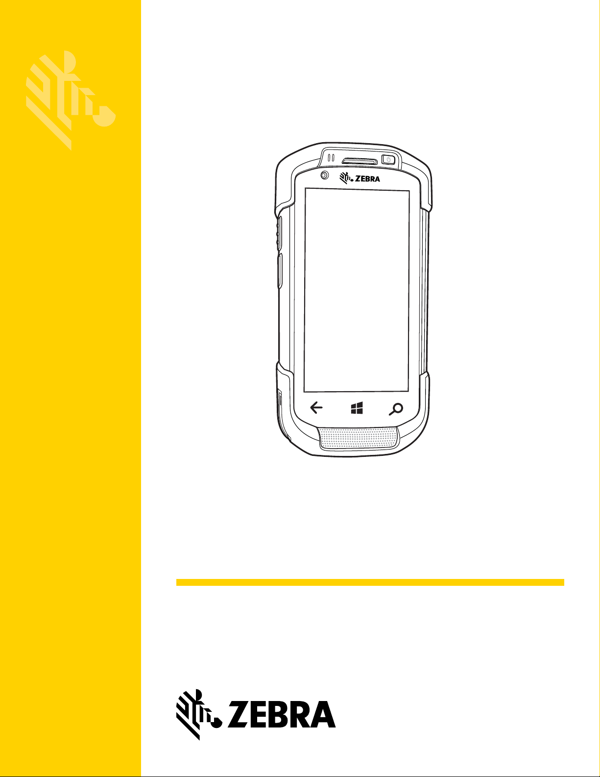
TC70x
MN-002885-03
Touch Computer
Integrator Guide for Windows 10
IoT Mobile Enterprise


TC70X
INTEGRATOR GUIDE WITH WINDOWS 10
IOT MOBILE ENTERPRISE
MN-002885-03
Rev . A
April 2018

ii TC70x Touch Computer User Guide with Windows 10 IoT Mobile Enterprise
No part of this publication may be reproduced or used in any form, or by any electrical or mechanical means, without
permission in writing from Zebra. This includes electronic or mechanical means, such as photocopying, recording, or
information storage and retrieval systems. The material in this manual is subject to change without notice.
The software is provided strictly on an “as is” basis. All software, including firmware, furnished to the user is on a
licensed basis. Zebra grants to the user a non-transfer able and non-exclu sive license to use each software or firmware
program delivered hereunder (licensed program). Except as noted below, such license may not be assigned,
sublicensed, or otherwise transferred by the user without prior written consent of Zebra. No right to copy a licensed
program in whole or in part is granted, except as permitted under copyright law. The user shall not modify, merge, or
incorporate any form or portion of a licensed program with other program material, create a derivative work from a
licensed program, or use a licensed program in a network without written permission from Zebra. The user agrees to
maintain Zebra’s copyright notice on the licensed programs delivered hereunder, and to include the same on any
authorized copies it makes, in whole or in part. The user agrees not to decompile, disassemble, decode, or reverse
engineer any licensed program delivered to the user or any portion thereof.
Zebra reserves the right to make changes to any software or product to improve reliability, function, or design.
Zebra does not assume any product liability arising out of, or in connection with, the application or use of any product,
circuit, or application described herein.
No license is granted, either expressly or by implication, estoppel, or otherwise under any Zebra Technologies
Corporation, intellectual property rights. An implied license only exists for equipment, circuits, and subsystems
contained in Zebra products.

Revision History
Changes to the original manual are listed below:
Change Date Description
01 Rev A 10/2016 Initial release.
02 Rev A 1/2017 Add support for Zebra Profile application.
03 Rev. A 4/2018 Update approved cleanser active ingredients.
iii

iv TC70x Touch Computer User Guide with Windows 10 IoT Mobile Enterprise

TABLE OF CONTENTS
Revision History................................................................................................................................. iii
Table of Contents
About This Guide
Introduction....................................................................................................................................... xi
Documentation Set ........................................................................................................................... xi
Configurations................................................................................................................................... xi
Software Versions............................................................................................................................. xii
Chapter Descriptions ........................................................................................................................ xii
Notational Conventions..................................................................................................................... xii
Icon Conventions............................................................................................................................. xiii
Related Documents ......................................................................................................................... xiii
Service Information.......................................................................................................................... xiii
Chapter 1: Getting Started
Introduction .................................................................................................................................... 1-1
Setup .............................................................................................................................................. 1-1
Installing a microSD Card ........................................................................................................ 1-1
Installing the Hand Strap and Battery ............................................................................................ 1-2
Installing the Battery ...................................................................................................................... 1-4
Charging the Battery ................................................................................................................ 1-4
Charging Indicators ............................................................................................................ 1-5
Replacing the Battery ..................................................................................................................... 1-5
Replacing the microSD Card ......................................................................................................... 1-7
Resetting the TC70x ...................................................................................................................... 1-9
Chapter 2: Accessories
Introduction .................................................................................................................................... 2-1
Accessories .................................................................................................................................... 2-1

vi TC70x Integrator Guide
2-Slot Charge Only Cradle ............................................................................................................. 2-4
Setup ........................................................................................................................................ 2-5
Charging the Device ................................................................................................................. 2-5
Charging the Spare Battery ...................................................................................................... 2-6
Battery Charging ...................................................................................................................... 2-7
Main Battery Charging ....................................................................................................... 2-7
Spare Battery Charging ...................................................................................................... 2-7
Charging Temperature ............................................................................................................. 2-7
2-Slot USB/Ethernet Cradle ........................................................................................................... 2-8
Setup ........................................................................................................................................ 2-9
Charging the Device ................................................................................................................. 2-9
Charging the Spare Battery .................................................................................................... 2-10
Battery Charging .................................................................................................................... 2-11
Main Battery Charging ..................................................................................................... 2-11
Spare Battery Charging .................................................................................................... 2-11
Charging Temperature ........................................................................................................... 2-12
USB/Ethernet Communication ............................................................................................... 2-12
Ethernet LED Indicators ................................................................................................... 2-12
5-Slot Charge Only Cradle ........................................................................................................... 2-14
Setup ...................................................................................................................................... 2-14
Charging the TC70x ............................................................................................................... 2-15
Battery Charging .................................................................................................................... 2-16
Main Battery Charging ..................................................................................................... 2-16
Charging Temperature ........................................................................................................... 2-16
Installing the Four Slot Battery Charger ................................................................................. 2-17
Removing the 4-Slot Battery Charger .................................................................................... 2-21
5-Slot Ethernet Cradle ................................................................................................................. 2-22
Setup ...................................................................................................................................... 2-23
Daisy-chaining Ethernet Cradles ............................................................................................ 2-23
LED Indicators ........................................................................................................................ 2-24
Charging the TC70x ............................................................................................................... 2-24
Battery Charging .................................................................................................................... 2-26
Main Battery Charging ..................................................................................................... 2-26
Spare Battery Charging .................................................................................................... 2-26
Charging Temperature ........................................................................................................... 2-27
Installing the 4-Slot Battery Charger ...................................................................................... 2-27
Removing the 4-Slot Battery Charger .................................................................................... 2-31
4-Slot Battery Charger ................................................................................................................. 2-33
Setup ...................................................................................................................................... 2-33
Charging Spare Batteries ....................................................................................................... 2-33
Battery Charging .................................................................................................................... 2-34
Spare Battery Charging .................................................................................................... 2-34
Charging Temperature ........................................................................................................... 2-35
Trigger Handle ............................................................................................................................. 2-36
Installing the Trigger Handle Plate ......................................................................................... 2-36
Inserting the Device into the Trigger Handle .......................................................................... 2-37
Removing the Device from the Trigger Handle ...................................................................... 2-38
Hand Strap Replacement ............................................................................................................. 2-39
TC7X Vehicle Communication Charging Cradle .......................................................................... 2-42
Requirements ......................................................................................................................... 2-42

Table of Contents vii
Mounting the Cradle to a Flat Surface ................................................................................... 2-43
Mounting the Cradle to a RAM Mount .................................................................................... 2-44
USB I/O Hub Power ............................................................................................................... 2-45
USB I/O Hub ................................................................................................................................ 2-46
Requirements ......................................................................................................................... 2-46
Mounting the USB I/O Hub to a Flat Surface ......................................................................... 2-47
Mounting the Cradle to a RAM Mount .................................................................................... 2-48
CLA Power Connection ................................................................................................................ 2-49
Hard-Wired Power Connection .............................................................................................. 2-49
Power to Vehicle Cradle ......................................................................................................... 2-51
Chapter 3: WLAN Configuration
Introduction .................................................................................................................................... 3-1
Configuring a WEP/WPA Wi-Fi Network .................................................................................. 3-1
Configuring a 802.1x Wi-Fi Network ........................................................................................ 3-2
User name and Password ........................................................................................................ 3-2
Certificate ................................................................................................................................. 3-3
Manually Adding a Wi-Fi Network ............................................................................................ 3-5
Configuring for a Proxy Server ................................................................................................. 3-5
Configuring the Device to Use a Static IP Address .................................................................. 3-6
Chapter 4: USB Communication
Introduction .................................................................................................................................... 4-1
Connecting to a Host Computer via USB ....................................................................................... 4-1
Disconnect from the Host Computer .............................................................................................. 4-2
Chapter 5: Settings
Introduction .................................................................................................................................... 5-1
System ........................................................................................................................................... 5-1
Devices .......................................................................................................................................... 5-1
Network & Wireless ........................................................................................................................ 5-2
Personalization .............................................................................................................................. 5-2
Accounts ........................................................................................................................................ 5-2
Time & language ............................................................................................................................ 5-2
Ease of Access .............................................................................................................................. 5-3
Privacy ........................................................................................................................................... 5-3
Update & Security .......................................................................................................................... 5-4
Extras ............................................................................................................................................. 5-4
Language Usage ............................................................................................................................ 5-4
Changing the Language Setting ............................................................................................... 5-4
Storage .......................................................................................................................................... 5-5
Chapter 6: Scanner Profiles
Introduction .................................................................................................................................... 6-1
Application Installation ................................................................................................................... 6-1
Profiles ........................................................................................................................................... 6-1

viii TC70x Integrator Guide
Creating a New Profile ............................................................................................................. 6-1
Configuring a Profile ................................................................................................................. 6-2
Using a Profile .......................................................................................................................... 6-6
Deleting a Profile ...................................................................................................................... 6-6
Decoders ........................................................................................................................................ 6-7
UPCA ................................................................................................................................. 6-7
UPCE0 ............................................................................................................................... 6-7
Code128 ............................................................................................................................. 6-7
ISBT128 ............................................................................................................................. 6-7
Code 11 .............................................................................................................................................................. 6-8
Code93 ............................................................................................................................... 6-8
Matrix 2 of 5 ....................................................................................................................... 6-8
Discrete 2 of 5 .................................................................................................................... 6-9
Codabar ............................................................................................................................. 6-9
Code39 ............................................................................................................................... 6-9
Trioptic 39 ........................................................................................................................ 6-10
ISBN ................................................................................................................................. 6-10
Interleaved 2 of 5 ............................................................................................................. 6-10
MSI ................................................................................................................................... 6-10
GS1 DataBar Limited ....................................................................................................... 6-11
UPCE1 ............................................................................................................................. 6-11
UPC EAN Params ............................................................................................................ 6-11
UPCCOUPON .................................................................................................................. 6-12
GS1128COUPON ............................................................................................................ 6-12
Decode Lengths ............................................................................................................... 6-13
Reader Params ............................................................................................................................ 6-13
Scan Params ............................................................................................................................... 6-13
Chapter 7: Administrator Utilities
Enterprise Assign Access .............................................................................................................. 7-1
Windows Imaging and Configuration Designer .............................................................................. 7-1
Encryption ...................................................................................................................................... 7-1
Mobile Device Management Administration ................................................................................... 7-3
Chapter 8: Security
Secure Certificates ......................................................................................................................... 8-1
Installing a Secure Certificate .................................................................................................. 8-1
FIPS 1040 ...................................................................................................................................... 8-3
Chapter 9: Provisioning
Introduction .................................................................................................................................... 9-1
Creating a Package ....................................................................................................................... 9-1
Provisioning During Factory Reboot .............................................................................................. 9-9
Using Removable Media .......................................................................................................... 9-9
Using Bar Codes .................................................................................................................... 9-11
Provisioning ...................................................................................................................... 9-11
Using NFC .............................................................................................................................. 9-14

Table of Contents ix
Manual Provisioning ..................................................................................................................... 9-17
Chapter 10: Application Deployment
Introduction .................................................................................................................................. 10-1
Application Installation ................................................................................................................. 10-1
Installing Applications Using the USB Connection ....................................................................... 10-1
Installing Applications Using a microSD Card ........................................................................ 10-2
Uninstalling an Application ........................................................................................................... 10-3
Windows Update .......................................................................................................................... 10-4
Choosing How Updates Install ............................................................................................... 10-4
Chapter 11: Field Medic
Introduction .................................................................................................................................. 11-1
Generating a Report ............................................................................................................... 11-1
Recording a Field Medic Report ....................................................................................... 11-1
View Log Files ........................................................................................................................ 11-3
Specify Advanced Options ..................................................................................................... 11-4
Specify Custom Loggers .................................................................................................. 11-5
Use Field Medic from a Command Prompt ............................................................................ 11-5
Syntax .............................................................................................................................. 11-5
Custom Logging ..................................................................................................................... 11-7
Create a Custom Profile XML File .................................................................................... 11-7
Add Custom Profile to Field Medic ................................................................................. 11-10
Chapter 12: Maintenance and Troubleshooting
Introduction .................................................................................................................................. 12-1
Maintaining the TC70x ................................................................................................................. 12-1
Battery Safety Guidelines ............................................................................................................ 12-1
Cleaning Instructions ................................................................................................................... 12-2
Approved Cleanser Active Ingredients ................................................................................... 12-2
Harmful Ingredients ................................................................................................................ 12-3
Cleaning Instructions .............................................................................................................. 12-3
Special Cleaning Notes .......................................................................................................... 12-3
Cleaning Materials Required .................................................................................................. 12-3
Cleaning Frequency ............................................................................................................... 12-3
Cleaning the TC70x ..................................................................................................................... 12-4
Housing .................................................................................................................................. 12-4
Display ................................................................................................................................... 12-4
Camera and Exit Window ....................................................................................................... 12-4
Connector Cleaning ............................................................................................................... 12-4
Cleaning Cradle Connectors .................................................................................................. 12-4
Troubleshooting ........................................................................................................................... 12-5
TC70x ..................................................................................................................................... 12-5
2-Slot Charge Only Cradle ..................................................................................................... 12-7
2-Slot USB/Ethernet Cradle ................................................................................................... 12-8
5-Slot Charge Only Cradle Troubleshooting ........................................................................ 12-10
5-Slot Ethernet Cradle Troubleshooting ............................................................................... 12-11

x TC70x Integrator Guide
4-Slot Battery Charger Troubleshooting ............................................................................... 12-11
Appendix A: Technical Specifications
Introduction ................................................................................................................................... A-1
TC70x ........................................................................................................................................... A-1
SE4750-SR Decode Distances ............................................................................................... A-4
I/O Connector Pin-Outs ........................................................................................................... A-5
2-Slot Charge Only Cradle Technical Specifications .............................................................. A-6
2-Slot USB/Ethernet Cradle Technical Specifications ............................................................. A-6
5-Slot Charge Only Cradle Technical Specifications .............................................................. A-7
5-Slot Ethernet Cradle Technical Specifications ..................................................................... A-8
4-Slot Battery Charger Technical Specifications ..................................................................... A-8
Charge Only Vehicle Cradle Technical Specifications ............................................................ A-9
Magnetic Stripe Reader Technical Specifications ................................................................... A-9
Trigger Handle Technical Specifications ............................................................................... A-10
Charging Cable Cup Technical Specifications ...................................................................... A-11
Snap-On USB Cable Technical Specifications ..................................................................... A-11
Snap-On Serial Cable Technical Specifications .................................................................... A-11
DEX Cable Technical Specifications ..................................................................................... A-12
2.5 mm Audio Adapter Technical Specifications ................................................................... A-12
Appendix B: Application Development
Development Tools ............................................................................................................. .......... B-1
Porting App to Windows 10 ........................................................................................................... B-1
Index

ABOUT THIS GUIDE
Introduction
This guide provides information about us ing the TC70x touch co mp u ter and accessories.
NOTE Screens and windows pictured in this guide are samples and can differ from actual screens.
Documentation Set
The documentation set for the TC70x provides information for specific user needs, and includes:
•
TC70x Quick Start Guide with Windows 10 IOT Mobile Enterprise - describes how to get the TC70x up and
running.
•
TC70x User Guide with Windows 10 IOT Mobile Enterprise - describes how to use the TC70x.
•
TC70x Integrator Guide with Windows 10 IOT Mobile Enterprise - describes how to set up the TC70x and
accessories.
Configurations
This guide covers the following configurations:
Configuration Radios Display Memory
TC700J WLAN: 802.11
a/b/g/n/d/h/i/w/ac
WP AN: Bluetooth
v4.0 Low Energy
4.7” High
Definition (1280 x
720) LCD
2 GB RAM / 16
GB Flash (SLC
High Reliability
Flash)
Data Capture
Options
2D imager and
integrated NFC
Operating
System
Windows 10 IoT
Mobile Enterprise

xii TC70x Integrator Guide
Software Versions
To determine the current software versions:
1. Swipe down from the top of the screen, and touch All settings > System > About.
2. Touch More Info button.
•
Model - Displays the model number.
•
Software - Displays the operating system type.
•
Version - Displays the software version number.
•
Microsoft OS build - Displays the software build number.
Chapter Descriptions
Topics covered in this guide are as follows:
•
Chapter 1, Getting Started provides information on getting the TC70x up and running for the first time.
•
Chapter 2, Accessories describes the available accessories and how to use them with the TC70x.
•
Chapter 3, WLAN Configuration provides information for configuring WLAN network.
•
Chapter 4, USB Communication describes how to connect the TC70x to a host computer using USB.
•
Chapter 5, Settings provides the settings for configuring the TC70x.
•
Chapter 6, Scanner Profiles provides instructions for create scanning profile using the Zebra Scanning
Profile application.
•
Chapter 7, Administrator Utilities provides information for using the suite of administrative tools for
configuring the TC70x.
•
Chapter 8, Security provides information about how to secure the device.
•
Chapter 9, Provisioning provides information for provision a device.
•
Chapter 10, Application Deployment provides information for developing and managing applications.
•
Chapter 11, Field Medic provide information on using the Field Medic application.
•
Chapter 12, Maintenance and Troubleshooting includes instructions on cleaning and storing the TC70x, and
provides troubleshooting solutions for potential problems during TC70x operation.
•
Appendix A, Technical Specifications provides the technical specifications for the TC70x.
•
Appendix B, Application Development provides information on developing applications for the device.
Notational Conventions
The following conventions are used in this document:

About This Guide xiii
•
Italics are used to highlight the following:
• Chapters and sections in this and related documents
• Icons on a screen.
•
Bold text is used to highlight the following:
• Dialog box, window, and screen names
• Drop-down list and list box names
• Check box and radio button names
• Button names on a screen.
•
Bullets (•) indicate:
• Action items
• Lists of alternatives
• Lists of required steps that are not necessarily seq ue nt ial
•
Sequential lists (for example, lists that describe step-by-step procedures) appear as numbered lists.
Icon Conventions
The documentation set is designed to give the reader more visual clues. The following graphic icons are used
throughout the documentation set. These icons and their associated meanings are described below.
NOTE NOTE contains information more important than the surrounding text, such as exceptions or
preconditions. They also refer the reader elsewhere for additional information, remind the reader how to
complete an action (when it is not part of the current procedure, for instance), or tell the reader where
something is located on the screen. There is no warning level associated with a note.
CAUTION The word CAUTION with the associated safety icon implies information that, if disregarded, may result
in minor or moderate injury, or serious product damage.
WARNING! The word WARNING with the associated safety icon implies information that, if disregarded,
could result in death or serious injury, or serious product damage.
Related Documents
•
TC70x Quick Start Guide with Windows 10 IoT Mobile Enterprise, p/n MN-002827-xx.
•
TC70x Regulatory Guide with Windows 10 IoT Mobile Enterprise, p/n MN-002884-xx.
•
TC70x User Guide with Windows 10 IoT Mobile Enterprise, p/n MN-002668-xx.
For the latest version of this guide and all guides, go to: http://www.zebra.com/support
Service Information
If you have a problem with the equipment, contact Customer Support in the region. Co ntact information is available
at: http://www.zebra.com/support
.
.
xiv TC70x Integrator Guide
When contacting support, please have the following information available:
•
Serial number of the unit (found on manufacturing label)
•
Model number or product name (found on manufacturing label)
•
Software type and version number
•
IMEI number
Customer Support responds to calls by email or telephone within the time limits set forth in support agreements.
If the problem cannot be solved by Customer Support, the user may need to return the equipment for servicing and
will be given specific directions. We are not responsible for any damages incurred during shipment if the approved
shipping container is not used. Shipping the units improperly can possibly void the warranty. Remove the SIM card
and/or microSD card from the device before shipping for service.
If the device was purchased from a business partner, contact that business partner for support.

CHAPTER 1 GETTING STARTED
Introduction
This chapter provides information for getting the device up and running for the first time.
Setup
Perform this procedure to start using the TC70x for the first time.
1. Install a micro secure digital (SD) card (optional).
2. Install hand strap (optional).
3. Install the battery.
4. Charge the TC70x.
5. Power on the TC70x.
Installing a microSD Card
The microSD card slot provides secondary non-volatile storage. The slot is locate d under the batte ry pack. Refer to
the documentation provided with the card for more information, and follow the manufacturer’s recommendations for
use.
CAUTION For proper electrostatic discharge (ESD) precautions to avoid damaging the SIM card. Proper ESD
precautions include, but not limited to, working on an ESD mat and ensuring that the user is properly
grounded.
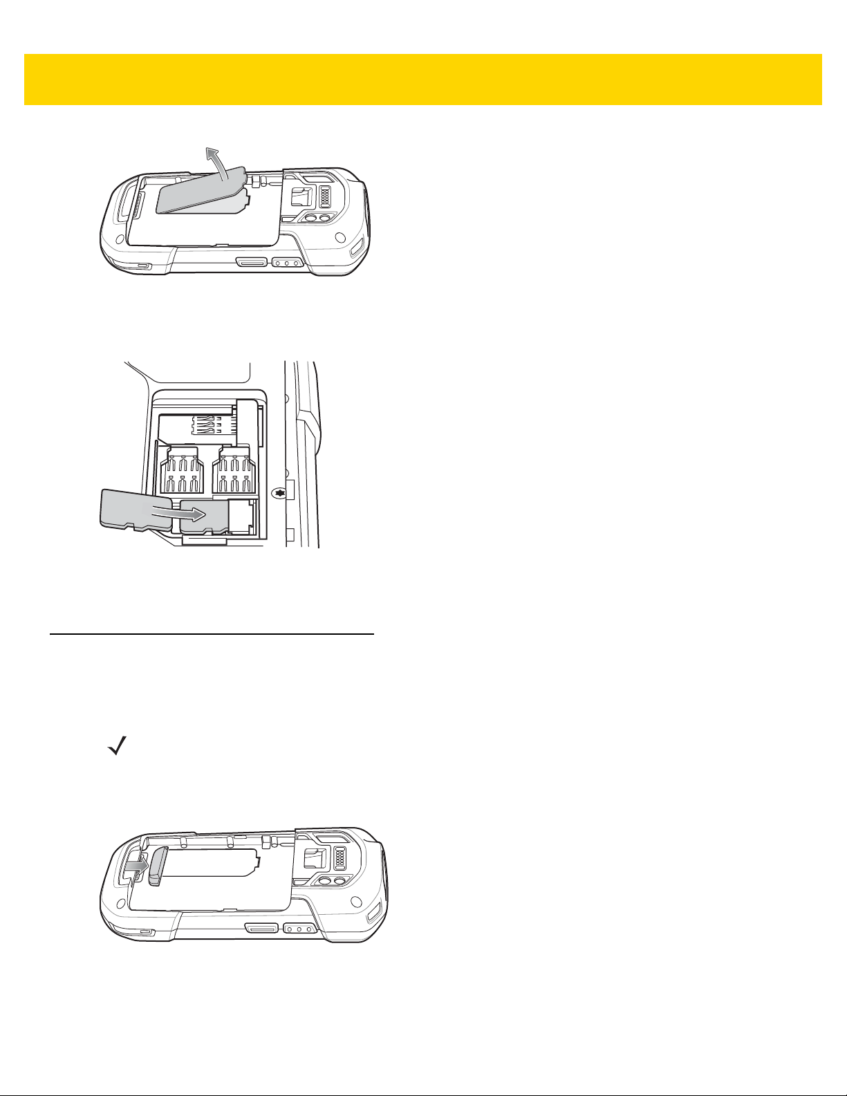
1. Remove the hand strap, if installed.
2. Lift the access door.
1 - 2 TC70x Integrator Guide
Figure 1-1 Lift Access Door
3. Insert the microSD card into the card holder door ensuring that the card slides into the holding tabs on each
side of the door.
Figure 1-2 Insert microSD Card in Holder
4. Re-install the access door.
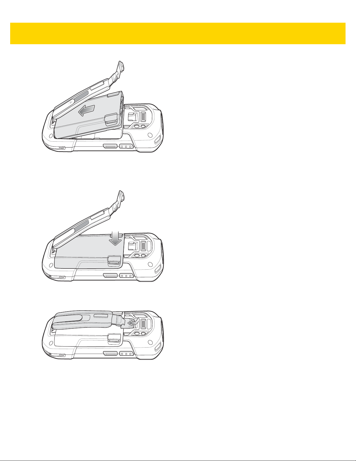
Installing the Hand Strap and Battery
To install the hand strap and battery:
NOTE Installation of the hand strap is optional. Skip this section if not installing the hand strap.
1. Remove the hand strap filler from the hand strap slot. Store the hand strap filler in a safe place for future
replacement.
Figure 1-3 Remove Filler
2. Insert the hand strap plate into the hand strap slot.

Figure 1-4 Insert Hand Strap
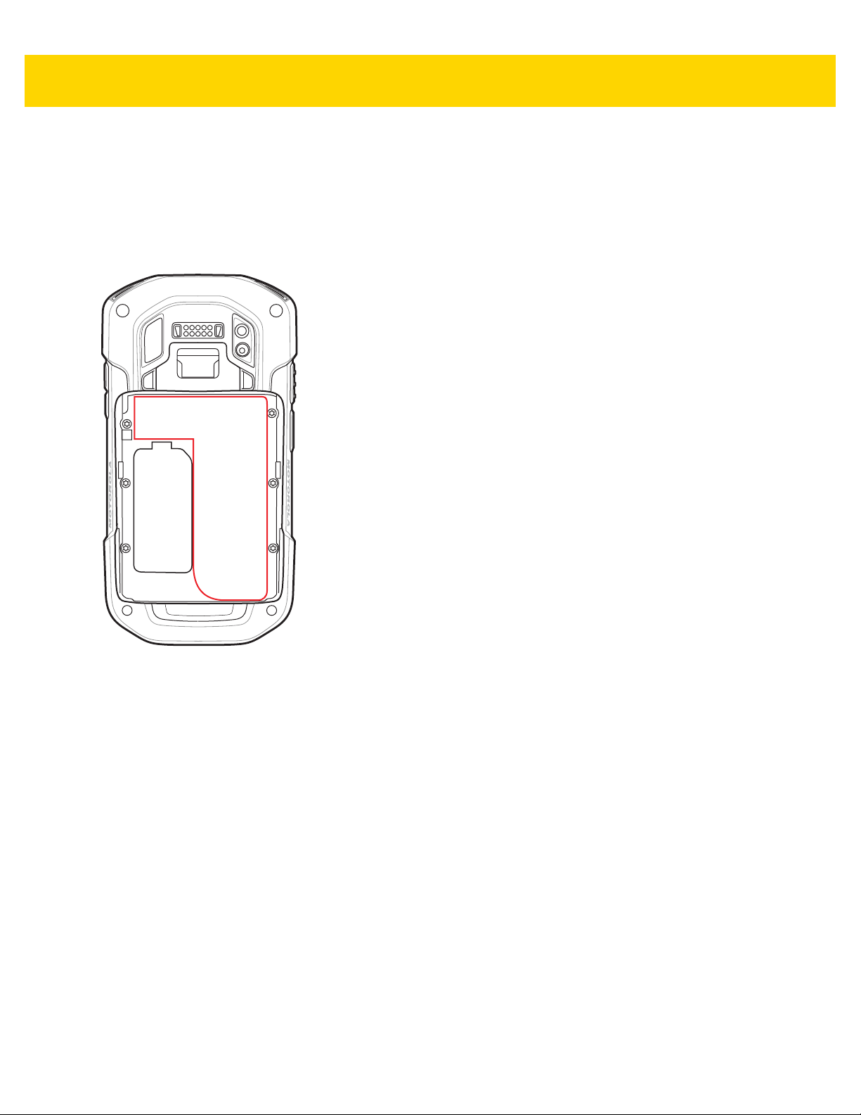
3. Insert the battery, bottom first, into the battery compartment in the back of the TC70x.
Getting Started 1 - 3
Figure 1-5 Insert Bottom of Battery into Battery Compartment
4. Rotate the top of the battery into the battery compartment.
5. Press the battery down into the battery compartment until the battery release latches snap into place.
Figure 1-6 Press Down on Battery
6. Place hand strap clip into hand strap mounting slot and pull down until it snaps into place.

1 - 4 TC70x Integrator Guide
Figure 1-7 Secure Hand Strap Clip
Installing the Battery
To install the battery:
1. Insert the battery, bottom first, into the battery compartment in the back of the TC70x.
Figure 1-8 Insert Bottom of Battery into Battery Compartment
2. Rotate the top of the battery into the battery compartment.
3. Press the battery down into the battery compartment until the battery release latches snap into place.
Figure 1-9 Press Down on Battery
Charging the Battery
Before using the TC70x for the first time, charge the main battery until the green Charging /Notification light emitting
diode (LED) remains lit. To charge the TC70x, use a cable or a cradle with the appropriate power supply. For
information about the accessories available for the TC70x, see Chapter 2, Accessories for more information.
• Snap-On USB Cable
• Charging Cable Cup
• 2-Slot Charge Only Cradle
• 2-Slot USB/Ethernet Cradle
• 5-Slot Charge Only Cradle
• 5-Slot Ethernet Cradle

Getting Started 1 - 5
• Charge Only Vehicle Cradle
• Auto Charging Cable Cup.
• Serial Cable Cup
The 4,620 mAh battery fully charges in approximately six hours at room temperature.
Charge batteries in temperatures from 0°C to 40°C (32°F to 104°F). The TC70x or accessory always performs
battery charging in a safe and intelligent manner. At higher temperatures (e.g. approximately +37°C (+98°F)) the
TC70x or accessory may for small periods of time alternately enable and disable battery charging to keep the
battery at acceptable temperatures. The TC70x or accessory indicates when charging is disabled due to abnormal
temperatures via its LED.
1. To charge the main battery, connect the charging accessory to the appropriate power source.
2. Insert the TC70x into a cradle or attach to a cable. The TC70x turns on and begins charging. The
Charging/Notification LED blinks amber while charging, then turns solid green when fully charged.
Charging Indicators
Table 1-1 Charging/Notification LED Charging Indicators
State Indication
Off TC70x is not charging. TC70x is not inserted correctly in the cradle or connected
Slow Blinking Amber (1 blink
every 2 seconds)
Solid Green Charging complete.
Fast Blinking Amber (2
blinks/second)
Slow Blinking Red (1 blink
every 2 seconds)
Solid Red Charging complete but the battery is at end of useful life.
Fast Blinking Red (2
blinks/second)
Replacing the Battery
to a power source. Charger/cradle is not powered.
TC70x is charging.
Charging error, e.g.:
Te mperature is too low or too high.
Charging has gone on too long without completion (typically eight hours).
TC70x is charging but the battery is at end of useful life.
Charging error but the battery is at end of useful life., e.g.:
Te mperature is too low or too high.
Charging has gone on too long without completion (typically eight hours).
CAUTION Do not add or remove SIM, SAM or microSD card during battery replacement.
1. Remove any accessory attached to the device.
2. Press the Power button until the menu appears.
3. Touch Battery Swap.
4. Follow the on-screen instructions.

1 - 6 TC70x Integrator Guide
5. Wait for the LED to turn off.
6. If hand strap is attached, slide the hand strap clip up toward the top of the TC70x and then lift.
Figure 1-10 Remove Hand Strap Clip
7. Press the two battery latches in.
Figure 1-11 Press Battery Latches
8. Lift the battery from the TC70x.

Getting Started 1 - 7
Figure 1-12 Lift the Battery
CAUTION Replace the battery within two minutes. After two minutes the device reboots and data may be lost.
9. Insert the replacement battery, bottom first, into the battery compartment in the back of the TC70x.
10. Press the battery down until the battery release latch snaps into place.
11. Replace the hand strap, if required.
12. Press and hold the Power button to turn on the TC70x.
Replacing the microSD Card
To replace the microSD card:
1. Press the Power button until the menu appears.
2. Touch Power off.
3. Touch OK.
4. If hand strap is attached, slide the hand strap clip up toward the top of the TC70x and then lift.

1 - 8 TC70x Integrator Guide
Figure 1-13 Remove Hand Strap Clip
5. Press the two battery latches in.
6. Lift the battery from the TC70x.
7. Lift the access door.
Figure 1-14 Remove Access Door
8. Remove microSD card from holder.
9. Press the access door down and ensure that it is properly seated.
10. Insert the replacement microSD card.
11. Replace the access door.
Figure 1-15 Replace Access Door
12. Insert the battery, bottom first, into the battery compartment in the back of the TC70x.
13. Press the battery down until the battery release latch snaps into place.
14. Replace the hand strap, if required.
15. Press and hold the Power button to turn on the TC70x.

Resetting the TC70x
The TC70x can be reset to factory settings. This will remove all data on the device.
To reset the TC70x:
1. Swipe down from the top of the screen, and touch All settings > Settings > About.
2. Touch Reset your phone.
Getting Started 1 - 9
Figure 1-16 Warning Dialog Box
3. In the Warning! dialog box, select Also erase SD card to erase all data on an install microSD card or select
Also remove provisioned content from my workspace to remove any previously install provisioning
packages.
4. Touch Yes. The device resets and then returns to factory settings.

1 - 10 TC70x Integrator Guide

CHAPTER 2 ACCESSORIES
Introduction
This chapter provides information for using the accessories for the device.
Accessories
This table lists the accessories available for the TC70x.
Table 2-1 Accessories
Accessory Part Number Description
Cradles
2-Slot Charge Only
Cradle
2-Slot USB/Ethernet
Cradle
5-Slot Charge Only
Cradle
5-Slot Ethernet Cradle CRD-TC7X-SE5EU1–01 Provides device charging and provides Ethernet
Cradle Mount KT-UNIVLBRKT-01R Mounts the 5-Slot Charge Only Cradle, 5-Slot Ethernet
CRD-TC7X-SEC2U1–01 Provides device and spare battery charging. Use with
power supply, p/n PWRS-14000-148R.
CRD-TC7X-SE2EU1–01 Provides device and spare battery charging and USB
communication with a host computer and Ethernet
communication with a network. Use with power supply,
p/n PWRS-14000-148R.
CRD-TC7X-SE5C1-01 Charges up to five devices. Use with power supply, p/n
PWRS-14000-241R and DC line cord, p/n
50-16002-029R. Can accommodate one 4-Slot Battery
Charger using the Battery Adapter Cup.
communication for up to five devices. Use with power
supply, p/n PWRS-14000-241R and DC line cord, p/n
50-16002-029R. Can accommodate one 4-Slot Battery
Charger using the Battery Adapter Cup.
Cradle, and 4-Slot Battery Charger to a wall or rack.

2 - 2 TC70x Integrator Guide
Table 2-1 Accessories (Continued)
Accessory Part Number Description
Batteries and Chargers
4,620 mAh
PowerPrecision Battery
4-Slot Spare Battery
Charger
Battery Charger Adapter
Cup
Vehicle Solutions
Charging Cable Cup CHG-TC7X-CLA1-01 Provides power to the device from a cigarette lighter
Charge Only Vehicle
Cradle
Cigarette Light Adapter
Auto Charge Cable
Hard-wire Auto Charge
Cable
RAM Mount RAM-B-166U Provides window mounting option for the Vehicle
BTRY-TC7X-46MA2-01
BTRY-TC7X-46MA2-10
SAC-TC7X-4BTYC1-01 Charges up to four battery packs. Use with power
CUP-SE-BTYADP1-01 Allows for one 4-Slot Battery Charger to be charged
CRD-TC7X-CVCD1-01 Charges and securely holds the device. Requires
CHG-AUTO-CLA1-01 Provides power to the Vehicle Cradle from a cigarette
CHG-AUTO-HWIRE1-01 Provides power to the Vehicle Cradle from the vehicle's
Replacement battery (single pack).
Replacement battery (10–pack).
supply, p/n PWRS-14000-148R.
and docked on the left most slot of the 5-Slot cradles
(maximum one per cradle).
socket.
power cable CHG-AUTO-CLA1-01 or
CHG-AUTOHWIRE1-01, sold separately.
lighter socket.
power panel.
Cradle.
RAM Twist Lock Suction Cup with Double Socket Arm
and Diamond Base Adapter. Overall Length: 6.75”.
RAM Mount Base RAM-B-238U RAM 2.43" x 1.31" Diamond Ball base with 1" ball.
Charge and Communication Cables
Charging Cable Cup CHG-TC7X-CBL1-01 Provides power to the device. Use with power supply,
p/n PWRS-14000-249R, sold separately.
Snap-On USB Cable CBL-TC7X-CBL1-01 Provides power to the device and USB communication
with a host computer. Use with power supply, p/n
PWRS-14000-249R, sold separately.
Snap-On Serial Cable CBL-TC7X-SERL1-01 Provides power and serial communication with a host
computer. Use with power supply, p/n
PWRS-14000-249R, sold separately.
Snap-On DEX Cable CBL-TC7X-DEX1-01 Provides electronic data exchange with devices such
as vending machines.
Audio Accessories
2.5 mm Audio Adapter ADP-TC7X-AUDIO1-01 Snaps onto the device and provides audio to a wired
headset with 2.5 mm plug.
2.5 mm Headset HDST-25MM-PTVP-01 Use for PTT and VoIP calls

Table 2-1 Accessories (Continued)
Accessory Part Number Description
Premium Headset RCH51 Premium Rugged headset.
Accessories 2 - 3
2.5 mm Quick
Disconnect Adapter
Cable
3.5 mm Audio Adapter ADP-TC7X-AUD35-01 Snaps onto the device and provides audio to a wired
3.5 mm Headset HDST-35MM-PTVP-01 Use for PTT and VoIP calls.
3.5 mm Quick
Disconnect Adapter
Cable
Scanning
Trigger Handle TRG-TC7X-SNP1-01 Adds gun-style handle with a scanner trigger for
Carrying Solutions
Soft Holster SG-TC7X-HLSTR1-01 TC7X soft holster.
Rigid Holster SG-TC7X-RHLSTR1-01 TC7X rigid holster.
Hand Strap SG-TC7X-HSTRP1-03 Replacement hand strap with hand strap mounting clip
Stylus and Coiled Tether SG-TC7X-STYLUS-03 TC7X stylus with coiled tether (3-pack).
25-124387-02R Provides connection to the RCH50/RCH51 headset.
headset with 3.5 mm plug.
ADP-35M-QDCBL1-01 Provides connection to the 3.5 mm Headset.
comfortable and productive scanning.
(3–pack).
Power Supplies
Power Supply PWRS-14000-249R Provides power to the device using the Snap-On USB
Cable, Snap-on Serial Cable or Charging Cable Cup.
Requires AC line cord.
Power Supply PWRS-14000-148R Provides power to the 2–Slot cradles and 4-Slot Spare
Battery Charger. Requires AC line cord.
Power Supply PWRS-14000-241R Provides power to the 5-Slot Charge Only cradle and
the 5-Slot Ethernet Cradle. Requires DC Line Cord, p/n
50–16002–029R and country specific three wire
grounded AC line cord sold separately.
DC Line Cord 50-16002-029R Provides power from the power supply to the 5-Slot
Charge Only Cradle and 5-Slot Ethernet Cradle .
2 - 4 TC70x Integrator Guide
Spare Battery Charging LED
Power LED
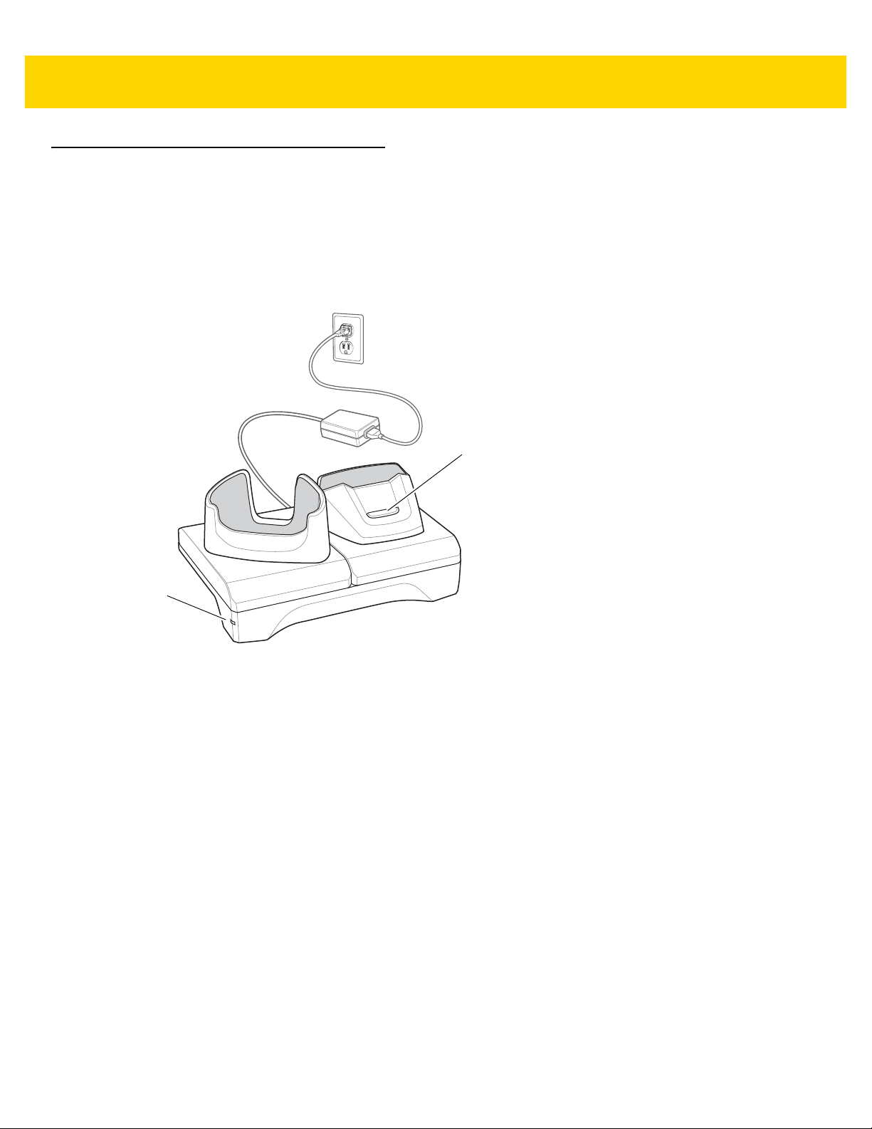
2-Slot Charge Only Cradle
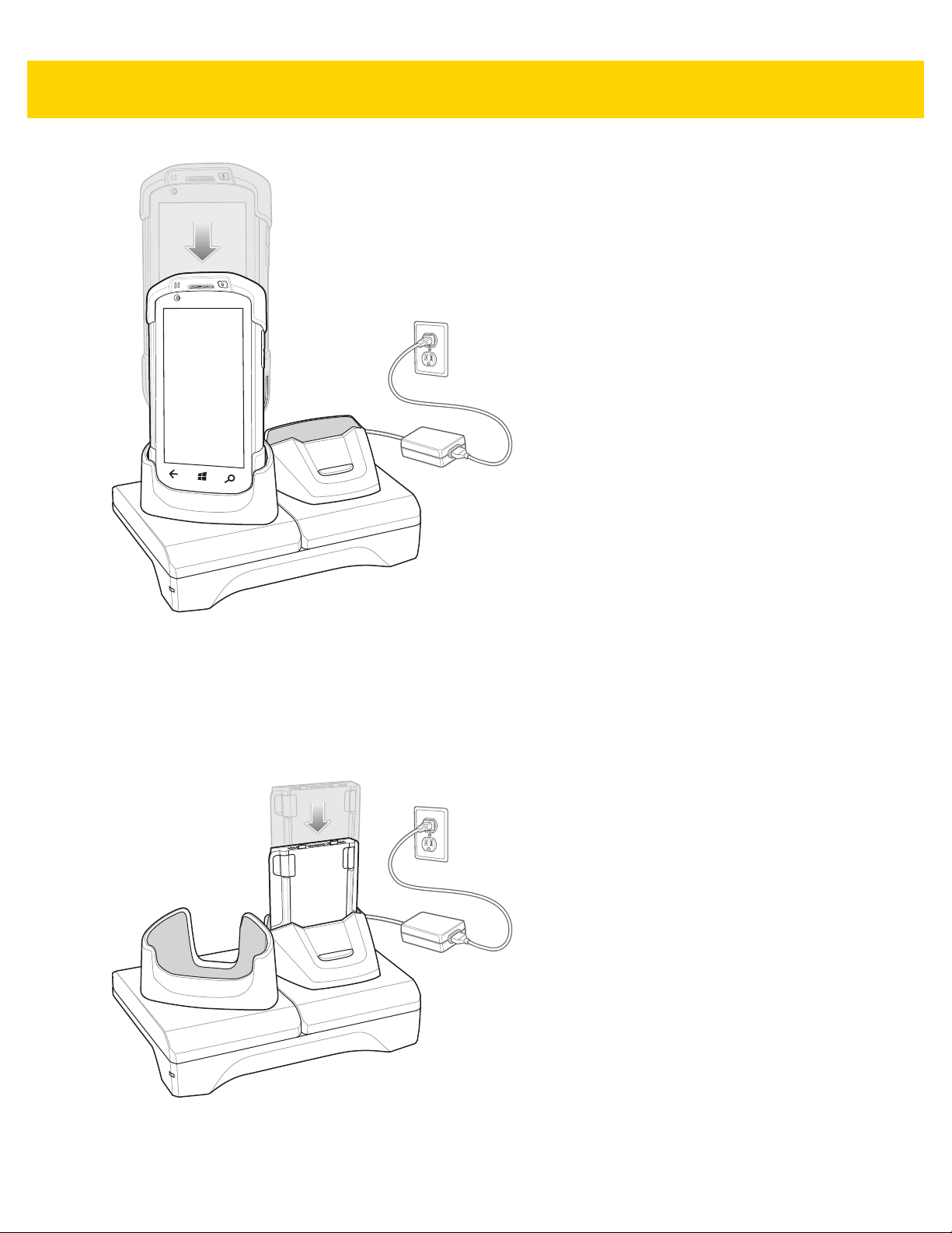
The 2-Slot Charge Only Cradle:
• Provides 5 VDC power for operating the device.
• Charges the device’s battery.
• Charges a spare battery.
Figure 2-1 2–Slot Charge Only Cradle

Setup
Accessories 2 - 5
Figure 2-2 2–Slot Charge Only Cradle
Charging the Device
1. Insert the device into the slot to begin charging.
2 - 6 TC70x Integrator Guide
Figure 2-3 Battery Charging
2. Ensure the device is seated properly.
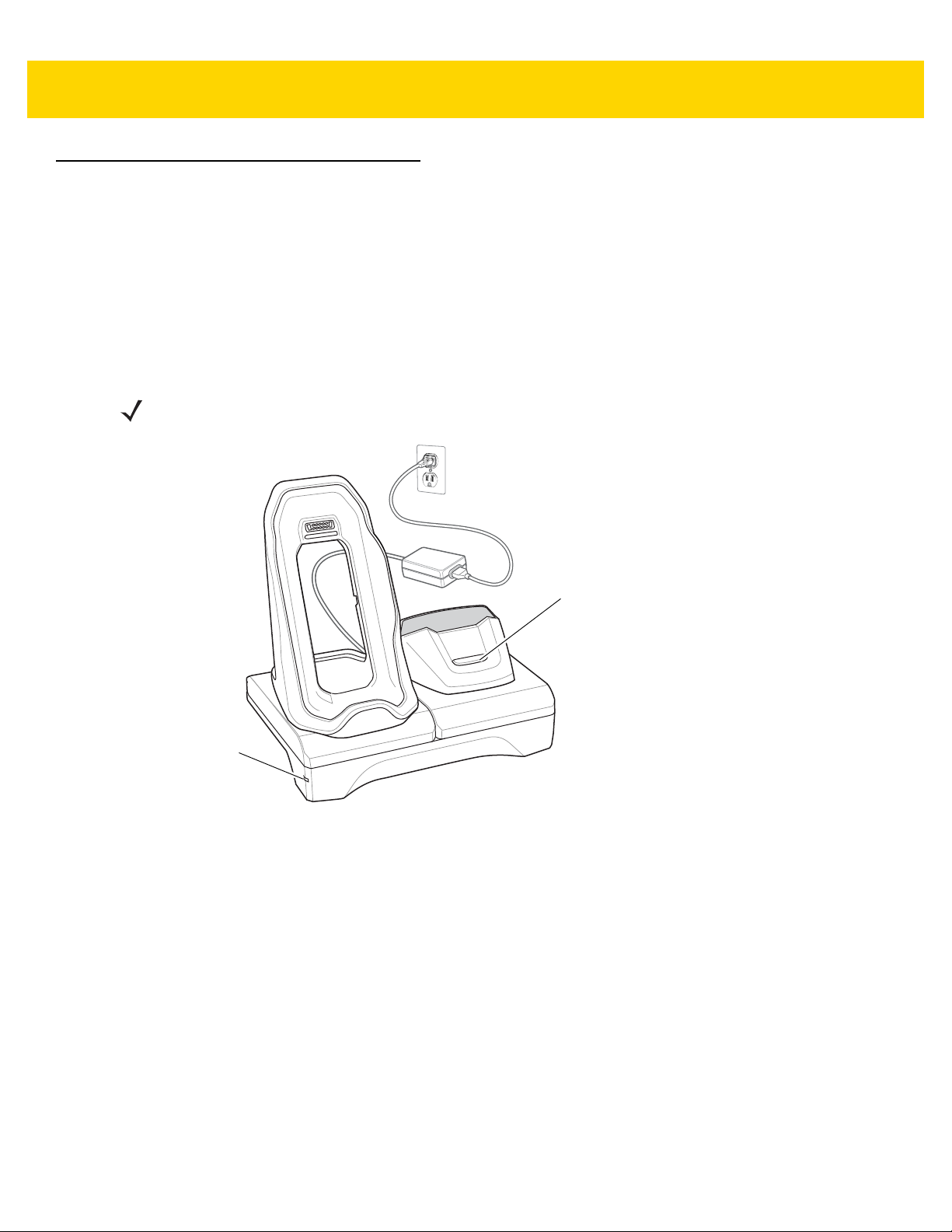
Charging the Spare Battery
1. Insert the battery into the right slot to begin charging.
Figure 2-4 Spare Battery Charging
2. Ensure the battery is seated properly.

Battery Charging
Main Battery Charging
The device’s Charging/Notification LED indicates the status of the battery charging in the device.
The 4,620 mAh battery fully charges in less than six hours at room temperature.
Spare Battery Charging
The Spare battery Charging LED on the cup indicates the status of the spar e battery charging.
The 4,620 mAh battery fully charges in less than six hours at room temperature.
Table 2-2 Spare Battery Charging LED Indicators
LED Indication
Slow Blinking Amber Spare battery is charging.
Solid Green Charging complete.
Accessories 2 - 7
Fast Blinking Amber Error in charging; check placement of spare battery.
Slow Blinking Red Spare battery is charging and battery is at the end of
useful life.
Solid Red Charging complete and battery is at the end of useful
life.
Fast Blinking Red Error in charging; check placement of spare battery and
battery is at the end of useful life.
Off No spare battery in slot; spare battery not placed
correctly; cradle is not powered.
Charging Temperature
Charge batteries in temperatures from 0°C to 40°C (32°F to 104°F). The device or cradle always performs battery
charging in a safe and intelligent manner . At higher temperatures (e.g. approximately +37°C (+98°F)) the device or
cradle may for small periods of time alternately enable and disable battery charging to keep the battery at
acceptable temperatures. The device and cradle indicates when charging is disabled due to abnormal
temperatures via its LED.
2 - 8 TC70x Integrator Guide
Spare Battery Charging LE
Power LED
2-Slot USB/Ethernet Cradle
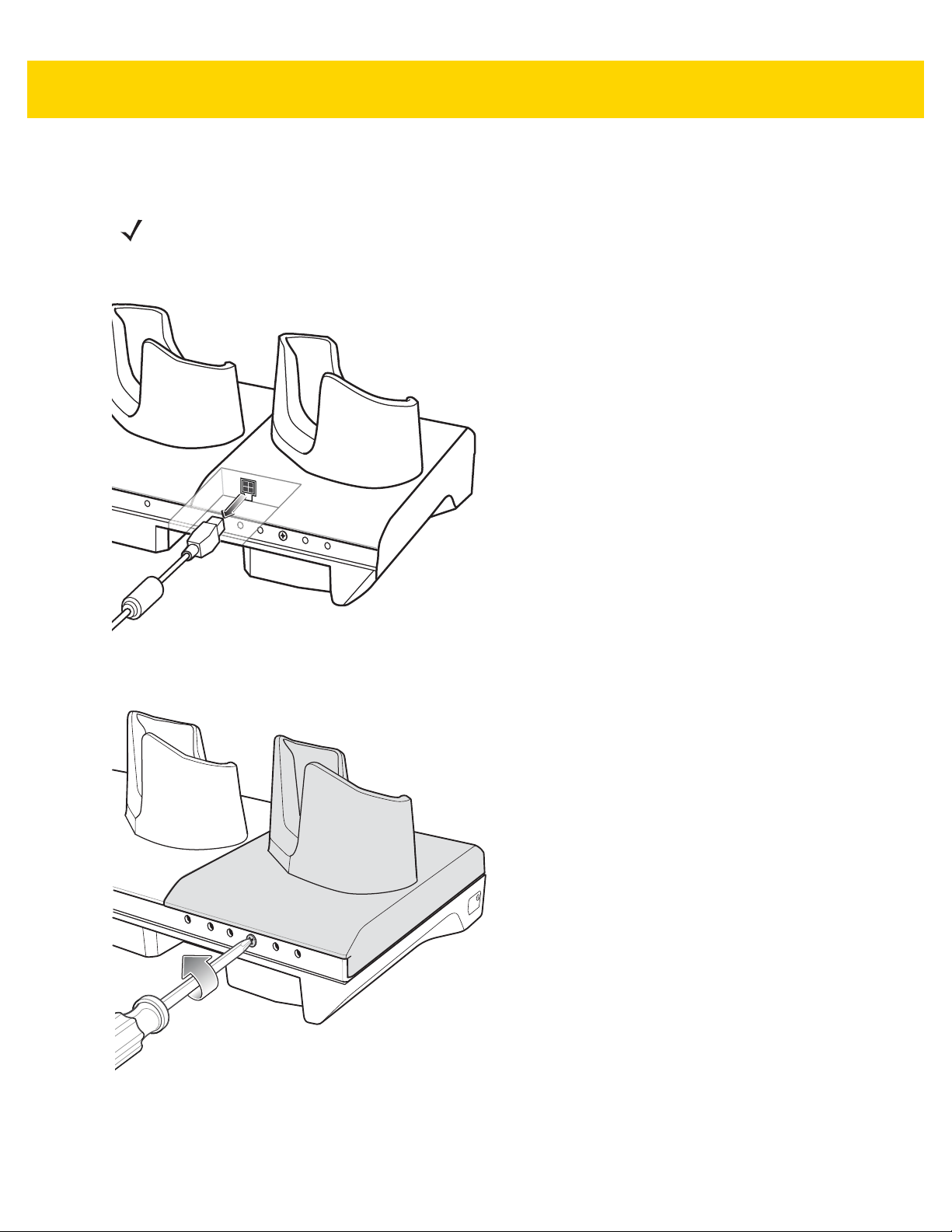
The 2-Slot USB/Ethernet Cradle:
• Provides 5.0 VDC power for operating the device.
• Charges the device’s battery.
• Charges a spare battery.
• Connects the device to an Ethernet network.
• Provides communication to a host computer using a USB cable.
NOTE Remove all attachments on the device, except the hand strap, before place onto the cradle.
Figure 2-5 2-Slot USB/Ethernet Cradle

Setup
Accessories 2 - 9
Figure 2-6 2–Slot USB/Ethernet Cradle
Charging the Device
1. Place the bottom of the device into the base.

2 - 10 TC70x Integrator Guide
Figure 2-7 Battery Charging
2. Rotate the top of the device until the connector on the back of the device mates with the connector on the
cradle.
3. Ensure the device is connected properly . The charging Charging/Notification LED on the device begins blinking
amber indicating that the device is charging.
Charging the Spare Battery
1. Insert the battery into the right slot to begin charging.

Figure 2-8 Spare Battery Charging
Accessories 2 - 11
2. Ensure the battery is seated properly.
Battery Charging
Main Battery Charging
The device’s Charging/Notification LED indicates the status of the battery charging in the device.
The 4,620 mAh battery fully charges in less than six hours at room temperature.
Spare Battery Charging
The Spare battery Charging LED on the cup indicates the status of the spar e battery charging.
The 4,620 mAh battery fully charges in less than six hours at room temperature.
Table 2-3 Spare Battery Charging LED Indicators
LED Indication
Slow Blinking Amber Spare battery is charging.
Solid Green Charging complete.
Fast Blinking Amber Error in charging; check placement of spare battery.
Slow Blinking Red Spare battery is charging and battery is at the end of
useful life.
Solid Red Charging complete and battery is at the end of useful
life.

2 - 12 TC70x Integrator Guide
Table 2-3 Spare Battery Charging LED Indicators (Continued)
LED Indication
Fast Blinking Red Error in charging; check placement of spare battery and
Off No spare battery in slot; spare battery not placed
Charging Temperature
Charge batteries in temperatures from 0°C to 40°C (32°F to 104°F). The device or cradle always performs battery
charging in a safe and intelligent manner . At higher temperatures (e.g. approximately +37°C (+98°F)) the device or
cradle may for small periods of time alternately enable and disable battery charging to keep the battery at
acceptable temperatures. The device and cradle indicates when charging is disabled due to abnormal
temperatures via its LED.
USB/Ethernet Communication
The 2–Slot USB/Ethernet Cradle provides both Ethernet communication with a network and USB communication
with a host computer. Prior to using the cradle for Ethernet or USB communication. Ensure that the switch on the
USB/Ethernet module is set properly.
battery is at the end of useful life.
correctly; cradle is not powered.
Turn the cradle over to view the module.
Figure 2-9 2–Slot USB/Ethernet Cradle Module Switch
For Ethernet communication, slide the switch to the position.
For USB communication, slide the switch to the position.
Place the switch in the center position to disable communications.
Ethernet LED Indicators
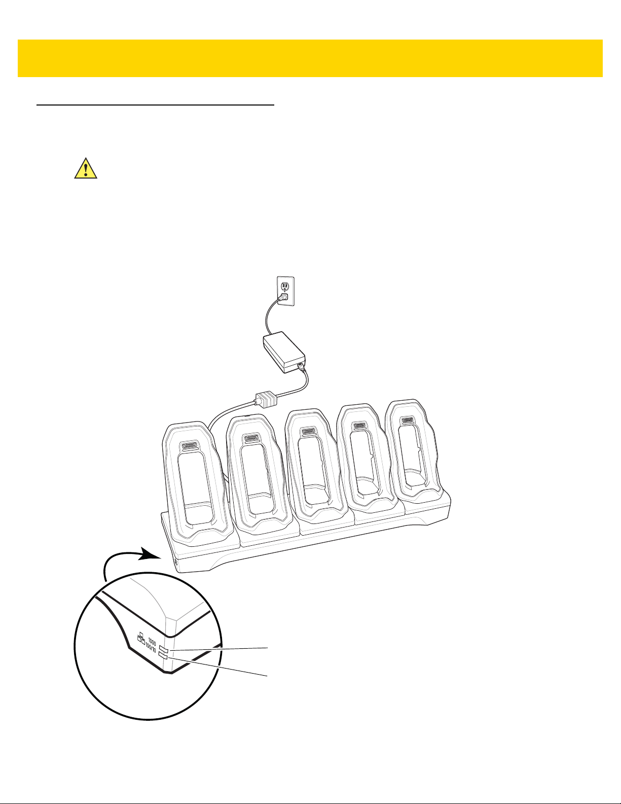
There are two LEDs on the USB/Ethernet Module RJ-45 connector. The green LED lights to indicate that the
transfer rate is 100 Mbps. When the LED is not lit the transfer rate is 10 Mbps. The yellow LED blinks to indicate
activity, or stays lit to indicate that a link is established. When it is not lit it indicates that there is no link.
Figure 2-10 LED Indicators

Table 2-4 USB/Ethernet Module LED Data Rate Indicators
Data Rate (1) Yellow LED (2) Green LED
100 Mbps On/Blink On
10 Mbps On/Blink Off
Accessories 2 - 13

2 - 14 TC70x Integrator Guide
Power LED
5-Slot Charge Only Cradle
The 5-Slot Charge Only Cradle:
• Provides 5 VDC power for operating the TC70x.
• Simultaneously charges up to five TC70xs and up to four TC70xs and on 4-Slot Battery Charger using the
Battery Charger Adapter. See the TC70x Integrator Guide for information on installing the 4-Slot Battery
Charger onto the cradle.
• Consists of a cradle base and cups that can be configured for various charging requirements.
Figure 2-11 5-Slot Charge Only Crad le
Setup
Figure 2-12 5-Slot Charge Only Cradle

Charging the TC70x
1. Insert the TC70x into a slot to begin charging.
Accessories 2 - 15
Figure 2-13 TC70x Battery Charging

2 - 16 TC70x Integrator Guide
Figure 2-14 5-Slot Charge Only Cradle with Four Slot Battery Charger
2. Ensure the TC70x is seated properly.
Battery Charging
Main Battery Charging
The device’s Charging/Notification LED indicates the status of the battery charging in the device.
The 4,620 mAh battery fully charges in less than six hours at room temperature.
Charging Temperature
Charge batteries in temperatures from 0°C to 40°C (32°F to 104°F). The device always performs battery charging
in a safe and intelligent manner. At higher temperatures (e.g. approximately +37°C (+98°F)) the device may for
small periods of time alternately enable and disable battery charging to keep the battery at acceptable
temperatures. The device indicates when charging is disabled due to abnormal temperatures via its LED.
Installing the Four Slot Battery Charger
NOTE The Battery Charger must be installed in the first slot only.
1. Remove power from the cradle.
Accessories 2 - 17
Figure 2-15 Remove Power from Cradle
2. Using a Phillips screwdriver, remove the screw securing the cup to the cradle base.
Figure 2-16 Remove Screw
3. Slide the cup to the front of the cradle.

2 - 18 TC70x Integrator Guide
Figure 2-17 Remove Cup
4. Carefully lift the cup up to expose the cup power cable.
5. Disconnect the cup power cable.
Figure 2-18 Disconnect Cup Power Cable
NOTE Place power cable into adapter to avoid pinching cable.
6. Connect the Battery Adapter power cable to the connector on the cradle.

Figure 2-19 Connect Adapter Power Cable
7. Place adapter onto cradle base and slide toward rear of cradle.
Accessories 2 - 19
Figure 2-20 Install Adapter
8. Using a Phillips screwdriver, secure adapter to cradle base with screw.

2 - 20 TC70x Integrator Guide
Figure 2-21 Secure adapter to Cradle
9. Align mounting holes on the bottom of the Four Slot Battery Charger with the stubs on the Battery Adapter.
Figure 2-22 Install Four Slot Battery Charger
10. Slide the Four Slot battery Charger down toward the front of the cradle.
11. Connect the output power plug into the power port on the Four Slot Battery Charger.

Figure 2-23 Connect Adapter Power Cable
Removing the 4-Slot Battery Charger
Accessories 2 - 21
1. Disconnect the output power plug from the 4-Slot Battery Charger.
2. At the back of the cup, press down on the release latch.
Figure 2-24 Press Release Latch
3. Slide the 4-Slot Battery Charger toward the front of the cradle.
4. Lift the 4-Slot off the cradle cup.
2 - 22 TC70x Integrator Guide
2
1
5-Slot Ethernet Cradle
CAUTION Ensure that you follow the guidelines for battery safety described in Battery Safety Guidelines on page
12-1.
The 5-Slot Ethernet Cradle:
• Provides 5.0 VDC power for operating the device.
• Connects the device (up to five) to an Ethernet network.
• Simultaneously charges up to five TC70xs or up to four TC70xs and one 4-Slot Battery Charger using the
Battery Charger Adapter.
1 1000 LED – Indicates 1 Gbps data rate.

2 100/10 LED – Indicates 100 Mbps or 10 Mbps data rate.
Setup
Connect the 5-Slot Ethernet cradle to a power source.
Accessories 2 - 23
Figure 2-25 5-Slot Ethernet Cradle Setup
Daisy-chaining Ethernet Cradles
Daisy-chain up to ten 5-Slot Ethernet cradles to connect several cradles to an Ethernet network. Use either a
straight or crossover cable. Daisy-chaining should not be attempted when the main Ethernet con nection to the first
cradle is 10 Mbps as throughput issues will almost certainly result.
To daisy-chain 5-Slot Ethernet cradles:
1. Connect power to each 5-Slot Ethernet cradle.
2. Connect an Ethernet cable to the one of the ports on the back of the first cradle and to the Ethernet switch.
3. Connect the other end of the Ethernet cable to one of the ports of the back of the second 5-Slot Ethernet
cradle.
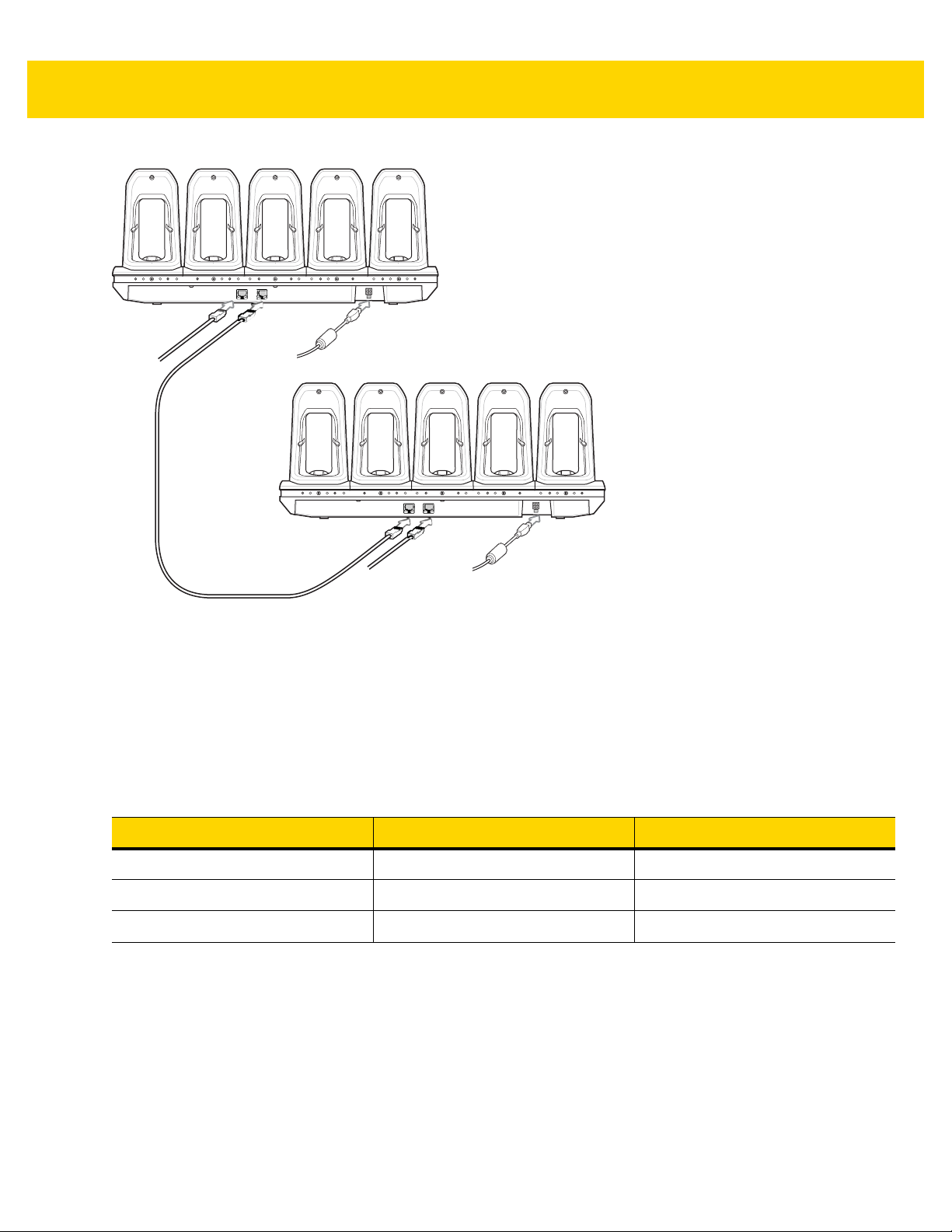
2 - 24 TC70x Integrator Guide
To Switch To Power Supply
To Power SupplyTo Next
Cradle
Figure 2-26 Daisy-chaining 5-Slot Ethernet Cradles
4. Connect additional cradles as described in step 2 and 3.
LED Indicators
There are two green LEDs on the side of the crad le. These green LEDs light and blink to ind ica te the data tr ansfer
rate.
Table 2-5 LED Data Rate Indicators
Data Rate 1000 LED 100/10 LED
1 Gbps On/Blink Off
100 Mbps Off On/Blink
10 Mbps Off On/Blink
Charging the TC70x
1. Insert the TC70x into a slot to begin charging.

Accessories 2 - 25
Figure 2-27 TC70x Battery Charging
2. Ensure the TC70x is seated properly.

2 - 26 TC70x Integrator Guide
Figure 2-28 5-Slot Ethernet Cradle with 4-Slot Battery Charger
Battery Charging
Main Battery Charging
The device’s Charging/Notification LED indicates the status of the battery charging in the device.
The 4,620 mAh battery fully charges in less than six hours at room temperature.
Spare Battery Charging
The Spare battery Charging LED on the cup indicates the status of the spar e battery charging.
The 4,620 mAh battery fully charges in less than six hours at room temperature.
Table 2-6 Spare Battery Charging LED Indicators
LED Indication
Slow Blinking Amber Spare battery is charging.
Solid Green Charging complete.
Fast Blinking Amber Error in charging; check placement of spare battery.
Slow Blinking Red Spare battery is charging and battery is at the end of
useful life.

Accessories 2 - 27
Table 2-6 Spare Battery Charging LED Indicators (Continued)
LED Indication
Solid Red Charging complete and battery is at the end of useful
life.
Fast Blinking Red Error in charging; check placement of spare battery
and battery is at the end of useful life.
Off No spare battery in slot; spare battery not placed
correctly; cradle is not powered.
Charging Temperature
Charge batteries in temperatures from 0°C to 40°C (32°F to 104°F). The device or cradle always performs battery
charging in a safe and intelligent manner . At higher temperatures (e.g. approximately +37°C (+98°F)) the device or
cradle may for small periods of time alternately enable and disable battery charging to keep the battery at
acceptable temperatures. The device and cradle indicates when charging is disabled due to abnormal
temperatures via its LED.
Installing the 4-Slot Battery Charger
NOTE The Battery Charger must be installed in the first slot only.
1. Remove power from the cradle.
Figure 2-29 Remove Power from Cradle
2. Using a Phillips screwdriver, remove the screw securing the cup to the cradle base.

2 - 28 TC70x Integrator Guide
Figure 2-30 Remove Screw
3. Slide the cup to the front of the cradle.
Figure 2-31 Remove Cup
4. Carefully lift the cup up to expose the cup power cable.
5. Disconnect the cup power cable and USB cable.

Figure 2-32 Disconnect Cup Cables
Accessories 2 - 29
NOTE Place power cable into adapter to avoid pinching cable.
6. Connect the Battery Adapter power cable to the connector on the cradle.
Figure 2-33 Connect Adapter Power Cable
7. Place adapter onto cradle base and slide toward rear of cradle.

2 - 30 TC70x Integrator Guide
Figure 2-34 Install Adapter
8. Using a Phillips screwdriver, secure adapter to cradle base with screw.
Figure 2-35 Secure adapter to Cradle
9. Align mounting holes on the bottom of the 4-Slot Battery Charger with the stubs on the Battery Adapter.

Accessories 2 - 31
Figure 2-36 Install 4-Slot Battery Charger
10. Slide the 4-Slot battery Charger down toward the front of the cradle.
11. Connect the output power plug into the power port on the 4-Slot Battery Charger.
Figure 2-37 Connect Adapter Power Cable
Removing the 4-Slot Battery Charger
1. Disconnect the output power plug from the 4-Slot Battery Charger.

2 - 32 TC70x Integrator Guide
2. At the back of the cup, press down on the release latch.
Figure 2-38 Press Release Latch
3. Slide the 4-Slot Battery Charger toward the front of the cradle.
4. Lift the 4-Slot off the cradle cup.

4-Slot Battery Charger
This section describes how to use the 4-Slot Battery Charger to charge up to four TC70x batteries.
Setup
Accessories 2 - 33
Figure 2-39 Four Slot Battery Charger Power Setup
Charging Spare Batteries
1. Connect the charger to a power source.
2. Insert the battery into a battery charging well and gently press down on the battery to ensure proper contact.

2 - 34 TC70x Integrator Guide
TC70x Battery
Battery Charge LED
Battery Slot
Figure 2-40 Four Slot Battery Charger
Battery Charging
Spare Battery Charging
Each Battery Charging LED indicates the status of the battery charging in each slot. The table below describes the
Battery Charging LED status.
The 4,620 mAh battery fully charges in less than six hours at room temperature.
Table 2-7 Battery LED Charging Indicators
LED Indication
Slow Blinking Amber Spare battery is charging.
Solid Green Charging complete.
Fast Blinking Amber Error in charging; check placement of spare battery.
Slow Blinking Red Spare battery is charging and battery is at the end of
useful life.
Solid Red Charging complete and battery is at the end of useful
life.
Fast Blinking Red Error in charging; check placement of spare battery
and battery is at the end of useful life.
Off No spare battery in slot; spare battery not placed
correctly; cradle is not powered.

Accessories 2 - 35
Charging Temperature
Charge batteries in temperatures from 0°C to 40°C (32°F to 104°F). The battery charger always performs battery
charging in a safe and intelligent manner. At higher temperatures (e.g. approximately +37°C (+98°F)) the battery
charger may for small periods of time alternately enable and disable battery charging to keep the battery at
acceptable temperatures. The battery charger indicates when charging is disabled due to abnormal temperatures
via its LED.
2 - 36 TC70x Integrator Guide
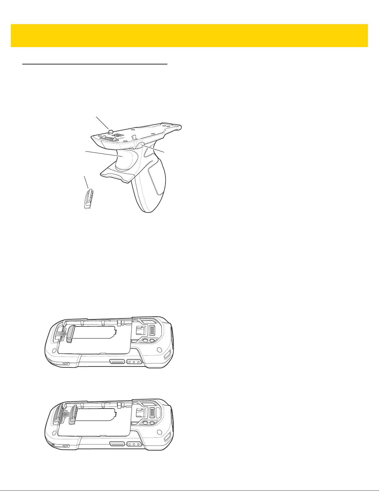
Trigger
Trigger Handle Plate
Latch
Release Button
Trigger Handle
The Trigg er Ha nd le ad ds a gun- style h an dle with a scan nin g trig ger to the device. It in crea se s comfo rt when using
the device in scan-intensive applications for extended periods of time.
Figure 2-41 Trigger Handle
Installing the Trigger Handle Plate
1. Press and hold the Power button until the menu appears.
2. Touch Power off.
3. Touch OK.
4. Press in the two battery latches.
5. Lift the battery from the device.
6. Remove the hand strap filler plate from the hand strap slot. Store the hand strap filler plate in a safe place for
future replacement.
Figure 2-42 Remove Hand Strap Plate
7. Insert the replacement hand strap plate into the hand strap slot.
Figure 2-43 Insert Trigger Handle Plate

Accessories 2 - 37
8. Insert the battery, bottom first, into the battery compartment in the back of the device.
9. Rotate the top of the battery into the battery compartment.
10. Press the battery down into the battery compartment until the battery release latches snap into place.
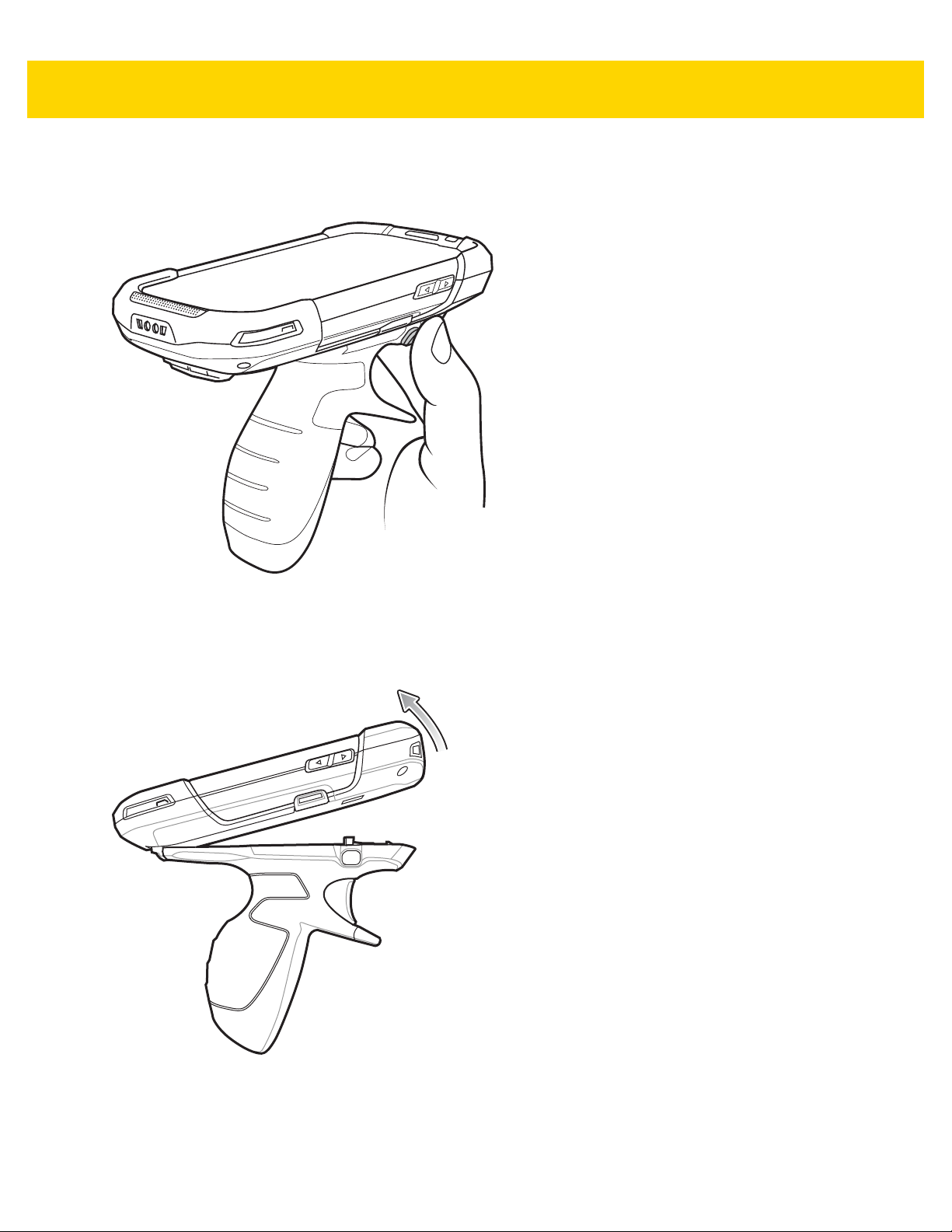
Inserting the Device into the Trigger Handle
1. Align the back of the Trigger handle with the Trigger Mounting Plate.
Figure 2-44 Connect Device to Trigger Handle
2. Press the two release latches.
3. Rotate the device down and press down until it snaps into place.
Figure 2-45 Rotate Device onto Trigger Handle
2 - 38 TC70x Integrator Guide
Removing the Device from the Trigger Handle
1. Press both Trigger Handle release latches.
Figure 2-46 Press Release Latches
2. Rotate the device up and remove from the Trigger handle.
3. Rotate the device down and press down until it snaps into place.
Figure 2-47 Rotate Device onto Trigger Handle

Hand Strap Replacement
CAUTION Close all running applications prior to replacing the hand strap.
1. Press and hold the Power button until the menu appears.
2. Touch Power Off.
3. Touch OK.
4. Remove the hand strap clip from the hand strap mounting slot.
Figure 2-48 Remove Hand Strap Clip
Accessories 2 - 39
5. Press the two battery latches in.
Figure 2-49 Press Battery Latches
6. Lift the battery from the TC70x.
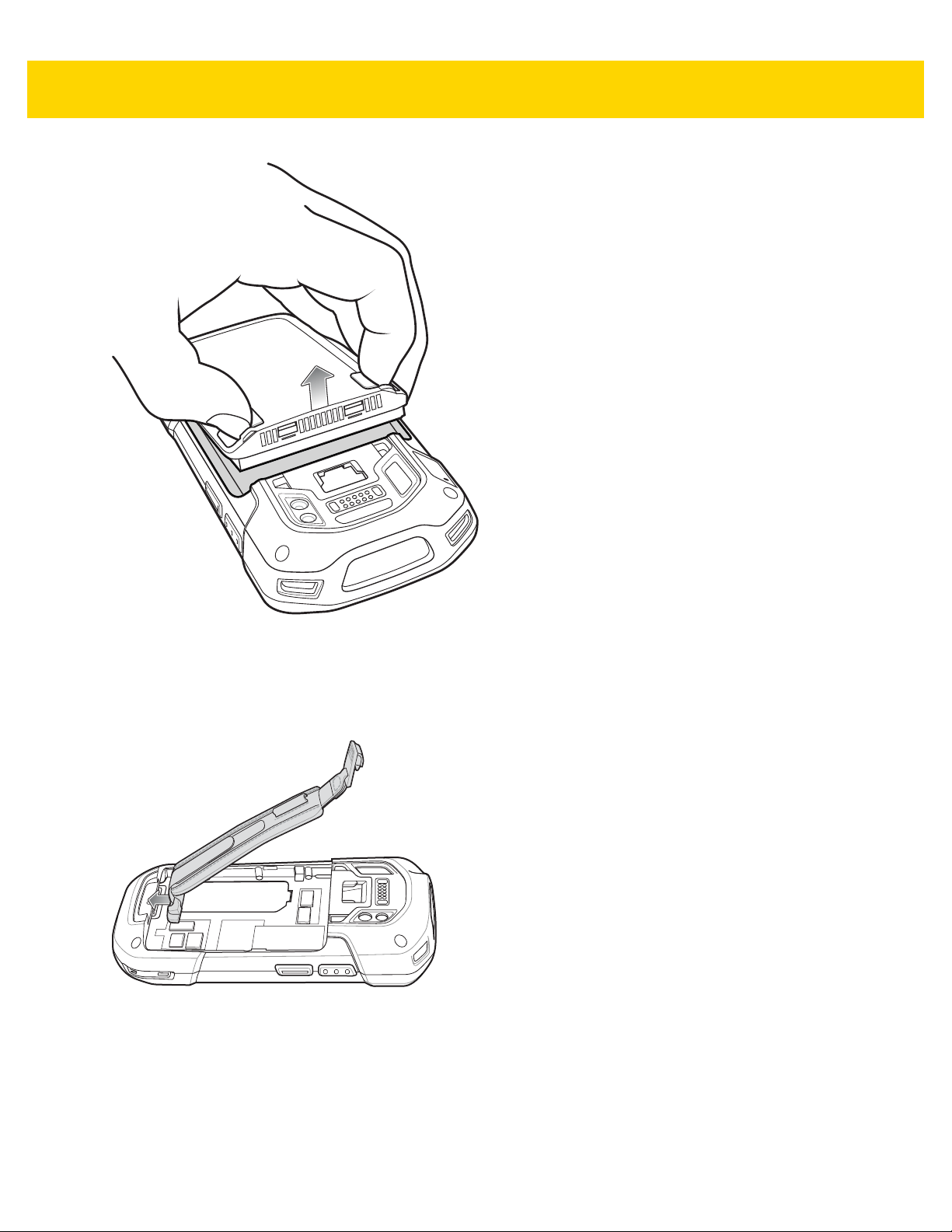
2 - 40 TC70x Integrator Guide
Figure 2-50 Lift the Battery
7. Remove the battery.
8. Remove the hand strap plate from the hand strap slot.
9. Insert the replacement hand strap plate into the hand strap slot.
Figure 2-51 Insert Hand Strap
10. Insert the battery, bottom first, into the battery compartment.
Accessories 2 - 41
Figure 2-52 Insert Bottom of Battery into Battery Compartment
11. Rotate the top of the battery into the battery compartment.
12. Press the battery down into the battery compartment until the battery release latches snap into place.
Figure 2-53 Press Down on Battery
13. Place hand strap clip into hand strap mounting slot and pull down until it snaps into place.
Figure 2-54 Secure Hand Strap Clip

2 - 42 TC70x Integrator Guide
FRONT VIEW
REAR VIEW
Mounting
Holes
Power Input Cable
Release Latch
TC7X Vehicle Communication Charging Cradle
Install the cradle into a vehicle. Once installed, the cradle:
• holds the TC75 securely in place
• provides power for operating the TC75 when connected to the optional USB I/O Hub.
Figure 2-55 Features
Requirements
For mounting on a flat surface:
• four M3 screws (included)
• four wall anchors (not included).
For mounting onto a RAM Mount
®
:
• RAM Mount (sold separately)
• Four M4 screws, lock washers and flat washers (included).

Accessories 2 - 43
38.1 mm
30.18 mm
1.12”
CAUTION ROAD SAFETY - Do not use the TC75 while driving. Park the vehicle first. Always ensure the TC75 is fully
inserted into the cradle. Do not place it on the seat or where it can break loose in a collision or sudden stop.
Lack of proper insertion may result in property damage or personal injury. Zebra is not responsible for any
loss resulting from the use of the products while driving. Remember: Safety comes first.
Mounting the Cradle to a Flat Surface
CAUTION Only mount the Vehicle Cradle in a vertical position. Never mount the vehicle cradle on the side or upside
down or on a wall that can be subject to impact or collision of greater than 10Gs, in accordance with SAE
J1455 Section 4.10.3.5.
1. Select a mounting location for the cradle. It should be flat, and must provide adequate support for the cradle.
2. Prepare the mounting surface, using the mounting te mplate below, with wall anchors that support the weight of
the cradle and device. The anchors should accept four M3 screws.
Figure 2-56 Mounting Template
3. Align the mounting holes on the mounting plate with the holes on the vehicle cradle.
Figure 2-57 Align Mounting Plate
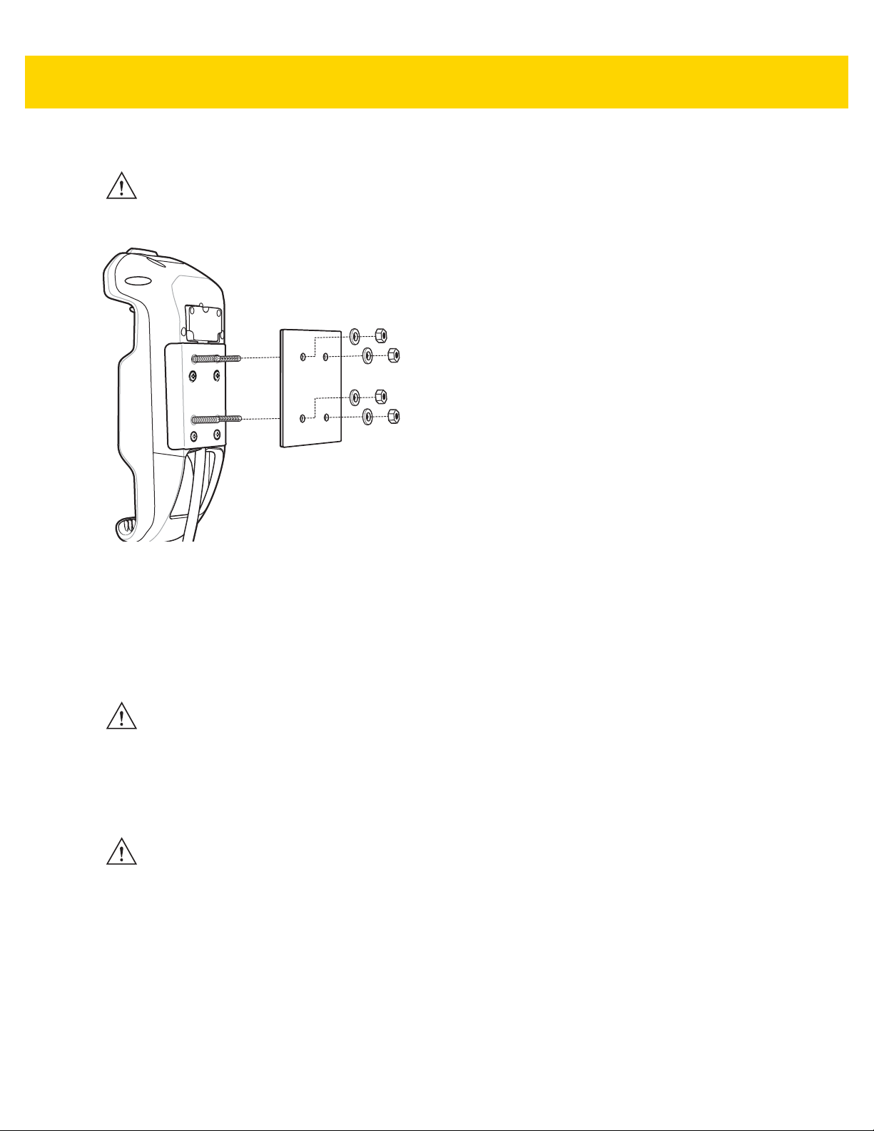
2 - 44 TC70x Integrator Guide
4. Fasten the mounting plate using four M3 screws (provided).
CAUTION Do not install a Vehicle Cradle on or near an air bag cover plate or within an aerobic zone. Also, do not
install it in a location that affects vehicle safety or driveability.
5. Align the mounting plate screws with the screw holes in the surface.
Figure 2-58 Align Screws with Holes in Surface
6. Tighten the screw to secure the cradle to the mounting plate.
Mounting the Cradle to a RAM Mount
To mount the cradle onto a RAM Mount:
CAUTION Only mount the Vehicle Cradle in a vertical position. Never mount the vehicle cradle on the side or upside
down or on a wall that can be subject to impact or collision of greater than 10Gs, in accordance with SAE
J1455 Section 4.10.3.5.
1. Follow the instructions that are provided with the RAM Mount for RAM Mount mounting instructions.
2. Align the vehicle cradle with the RAM Mount ball base.
3. Secure the vehicle cradle to the ball base using M4 screws, lock washers and flat washers (provided).
CAUTION Do not install a Vehicle Cradle on or near an air bag cover plate or within an aerobic zone. Also, do not
install it in a location that affects vehicle safety or driveability.

Figure 2-59 Align with RAM Mount
1
2
Accessories 2 - 45
4. Secure the RAM Mount to the vehicle depending upon the type of RAM Mount. See instructions provided with
RAM Mount.
5. Tighten the screw to secure the cradle to the mounting plate.
6. Adjust RAM Mount according to RAM Mount instructions.
USB I/O Hub Power
To connect the USB I/O Hub to the vehicle cradle:
1. Connect the Power Input Connector to the USB I/O Hub Power Output connector.
2. Tighten thumb screws.
Figure 2-60 USB I/O Hub Connection

2 - 46 TC70x Integrator Guide
FRONT VIEW
REAR VIEW
Mounting
Screw Holes
Power and Communication Connector
Cable Cover
USB Port Access
Cover
Power Input
Connector
Audio
Connector
(3.5 mm)
USB I/O Hub
Install the USB I/O Hub into a vehicle. Once installed, the USB I/O Hub:
• provides power to a vehicle cradle
• provides USB hub for three USB devices (such as printers)
• provides a powered USB port for charging another device.
The USB I/O Hub is powered by the vehicle’s 12V or 24V electrical system. The operating voltage range is 9V to
32V and supplies a maximum current of 3A to the vehicle cradle and 1.5 A to the four USB ports simultaneously.
Figure 2-61 Features
Requirements
For mounting on a flat surface:
• four M3 screws (included)
• four wall anchors (not included).
For mounting onto a RAM Mount
• RAM Mount (sold separately)
• Four M4 screws, lock washers and flat washers (included).
For CLA power connection:
• CLA (not included), p/n CHG-AUTO-CLA1-01
For hard-wired power connection:
®
:

Accessories 2 - 47
38.1 mm
30.18 mm
1.12”
• power input cable (included), p/n CHG-AUTO-HWIRE1-01
• UL Listed in-line fuse rated 250V, 5A (included), must be used if not connecting to vehicle’s fuse panel
• in-line fuse holder (included), must be used if not connecting to vehicle’s fuse panel.
CAUTION ROAD SAFETY - Do not use the device while driving . Park the vehicle first. Always ensure the device is
fully inserted into the cradle. Do not place it on the seat or where it can break loose in a collision or sudden
stop. Lack of proper insertion may result in property damage or personal injury. Zebra is not responsible for
any loss resulting from the use of the products while driving. Remember: Safety comes first.
Mounting the USB I/O Hub to a Flat Surface
CAUTION Only mount the USB I/O Hub in a vertical position. Never mount the USB I/O Hub on the side or upside
down or on a wall that can be subject to impact or collision of greater than 10Gs, in accordance with SAE
J1455 Section 4.10.3.5.
1. Select a mounting location for the cradle. It should be flat, and must provide adequ ate sup port for th e USB I/O
Hub.
2. Prepare the mounting surface, using the mounting te mplate below, with wall anchors that support the weight of
the USB I/O Hub. The anchors should accept four M3 screws.
Figure 2-62 Mounting Templates
3. Position the mounting plate on the mounting surface.
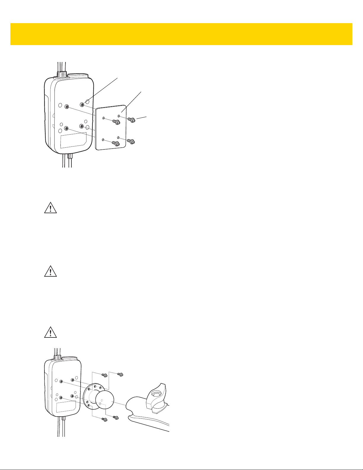
2 - 48 TC70x Integrator Guide
Mounting Holes
Flat Surface
Screws
Figure 2-63 Align Screws with Holes in Surface
4. Fasten the mounting plate using four M3 screws (provided).
CAUTION Do not install the USB I/O Hub on or near an air bag cover plate or within an aerobic zone. Also, do not
install it in a location that affects vehicle safety or driveability.
Mounting the Cradle to a RAM Mount
To mount the USB I/O Hub onto a RAM Mount:
CAUTION Only mount the USB I/O Hub in a vertical position. Never mount the USB I/O Hub on the side or upside
down or on a wall that can be subject to impact or collision of greater than 10Gs, in accordance with SAE
J1455 Section 4.10.3.5.
1. Follow the instructions that are provided with the RAM Mount for RAM Mount mounting instructions.
2. Align the mounting plate with the RAM Mount ball base.
3. Secure the mounting plate to the ball base using M4 screws, lock washers and flat washers (provided).
CAUTION Do not install the USB I/O Hub on or near an air bag cover plate or within an aerobic zone. Also, do not
install it in a location that affects vehicle safety or driveability.
Figure 2-64 Align with RAM Mount
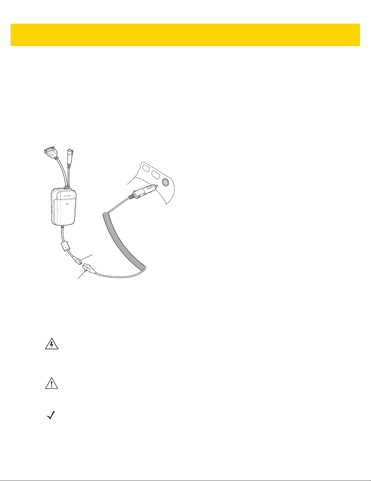
Accessories 2 - 49
Cigarette Lighter Adapter
Power Input
Connector
Collar
4. Secure the RAM Mount to the vehicle depending upon the type of RAM Mount. See instructions provided with
RAM Mount.
5. Adjust RAM Mount according to RAM Mount instructions.
CLA Power Connection
To connect the Cigarette Lighter Adapter (CLA) to the USB I/O Hub:
1. Ensure that the connector collar is installed on the connector.
2. Connect the CLA power output connector to the Power Input Connector on the USB I/O Hub.
3. Plug the CLA into a power outlet (cigarette lighter receptacle).
Figure 2-65 CLA Power Connection
Hard-Wired Power Connection
Please read all of these instructions before beginning.
WARNING! A properly trained technician must perform the power connection. Impro per connection can
damage your USB I/O Hub or mobile computer. Refer to the vehicle’s Owner’s Manual for
instructions for removing power.
To connect the cradle to power:
CAUTION When setting up connection for this USB I/O Hub, only use the power input cable provided with this USB I/O
Hub.
1. Locate the vehicle power source.
NOTEThe ideal location for connecting the USB I/O Hub power input cable would be an accessory output in your vehicle’s fuse
panel. The USB I/O Hub should be added to a circuit with a maximum load capacity for the USB I/O Hub and the original
circuit. Refer to the vehicle’s Owner’s Manual for identification of the circuit.
If a fused output is not available, the USB I/O Hub must be installed with the provided in-line fuse holder and UL Listed 5A
fuse. The fuse protects the vehicle from an electrical short on the power line to the USB I/O Hub.
To use the USB I/O Hub to charge the device, when the vehicle’s ignition is off, connect the USB I/O Hub to unswitched power.

2 - 50 TC70x Integrator Guide
Shield
Wire (bare
wire)
Ground
Wire
(black)
V+ Power (red)
5A Fuse and In-line
Fuse Holder (optional)
Power Input
Connector
Power Connector
Collar
2. Route the power input cable from the USB I/O Hub’s power port to th e connectio n point for the vehicle’s power
source.
NOTEThe means of routing and securing the power input cable from the USB I/O Hub through to the vehicle power source is
extremely important. Hazards associated with improper wiring can be severe. To avoid unintentional contact between the wire
and any sharp edges, provide the cable with proper bushings and clamping where it passes through openings. If the wire is
subjected to sharp surfaces and excess engine vibration, the wiring harness insulation can wear away, causing a short
between the bare wire and chassis. This can start a fire. To avoid any mishaps, all wiring should be routed away from moving
parts, high temperature areas and any contaminants.
3. When using the supplied in-line fuse holder (which must be used if not connecting to vehicle’s fuse panel):
a. Ensure the fuse holder contains a 5A UL Listed slow-blow fuse.
b. Splice the fuse holder to the end of the red V+ wire, as shown below. Make the distance from the fuse to
the power connection point as short as possible.
Figure 2-66 Hard Wired Power Connection
4. Prepare the cable termination.
5. Ensure that the connector collar is installed on the connector.
6. Connect the power connector to the power Input Connector on the USB I/O Hub.
To see if the USB I/O Hub has power, connect to a vehicle cradle and insert a device into the cradle. The Charging
LED on the device indicates charging. See the device User Guide for charging indications.
a. Red wire: connect to a +12/24 V vehicle power source.
b. Black wire and Shield wire: connect to vehicle ground wire or chassis ground.
NOTE How the cable terminates depends on the vehicle. If the vehicle has a power output connector, then you must
attach a mating connector to the end of the power cable. You may be able to connect to a fuse panel with a
simple blade terminal or commercially available connector. Consult the vehicle Owner’s Manual for information
on how to access the power supply in the vehicle.

Accessories 2 - 51
Vehicle Cradle Power and
Communication Connector
Power and Communication
Connector
1
2
Power to Vehicle Cradle
The USB I/O Hub can provide power to a Vehicle Cradle.
1. Connect the Power Output Cable connector to the Power Input Cable connector of the Vehicle Cradle.
2. Tighten thumbscrews by hand until tight.
Figure 2-67 Power to Vehicle Cradle

2 - 52 TC70x Integrator Guide

CHAPTER 3 WLAN CONFIGURATION
Introduction
Wireless local area networks (WLANs) allow the TC70x to communicate wirelessly inside a building. Before using
the TC70x on a WLAN, the facility must be set up with the required hardware to run the WLAN (sometimes known
as infrastructure). The infrastructure and the TC70x must both be properly configured to enable this
communication.
Refer to the documentation provided with the infrastructure (access points (APs), access ports, switches, Radius
servers, etc.) for instructions on how to set up the infrastructure.
Once the infrastructure is set up to enforce the chosen WLAN security scheme, use the Wireless & networks
settings configure the TC70x to match the security scheme.
The TC70x supports the following WLAN security options:
• Open
• Wireless Equivalent Privacy (WEP).
• Wi-Fi Protected Access (WPA)/WPA2 Personal (PSK).
• 802.11x.
The Status bar displays icons that indicate Wi-Fi network availability and Wi-Fi status.
NOTE Turn off Wi-Fi when not using it, to extend the life of the battery.
Configuring a WEP/WPA Wi-Fi Network
To set up a WEP/WPA Wi-Fi network:
1. Swipe down from the top of the screen, and touch All settings > Network & wireless > Wi-Fi.
2. Touch the Wi-Fi networking switch to turn on the Wi-Fi radio.
3. The device searches for WLANs in the area and lists them on the screen.
4. Scroll through the list and select the desired WLAN network.
5. Touch the desired network.

3 - 2 TC70x Integrator Guide
Figure 3-1 WEP WLAN Network Security Dialog Box
6. In the Password text box, enter the password.
7. Touch Done.
NOTE By default, the network Proxy is set to None and the IP settings is set to DHCP. See Configuring for a
Proxy Server on page 3-5 for setting connection to a proxy server and see Configuring the Device to Use
a Static IP Address on page 3-6 for setting the device to use a static IP address.
8. Touch .
Configuring a 802.1x Wi-Fi Network
Configure a Wi-Fi network using:
• User Name and Password
• Certificate.
User name and Password
To set up a Wi-Fi network using a user name and password:
1. Swipe down from the top of the screen, and touch All settings > Network & wireless > Wi-Fi.
2. Touch the Wi-Fi networking switch to turn on the Wi-Fi radio.
3. The device searches for WLANs in the area and lists them on the screen.
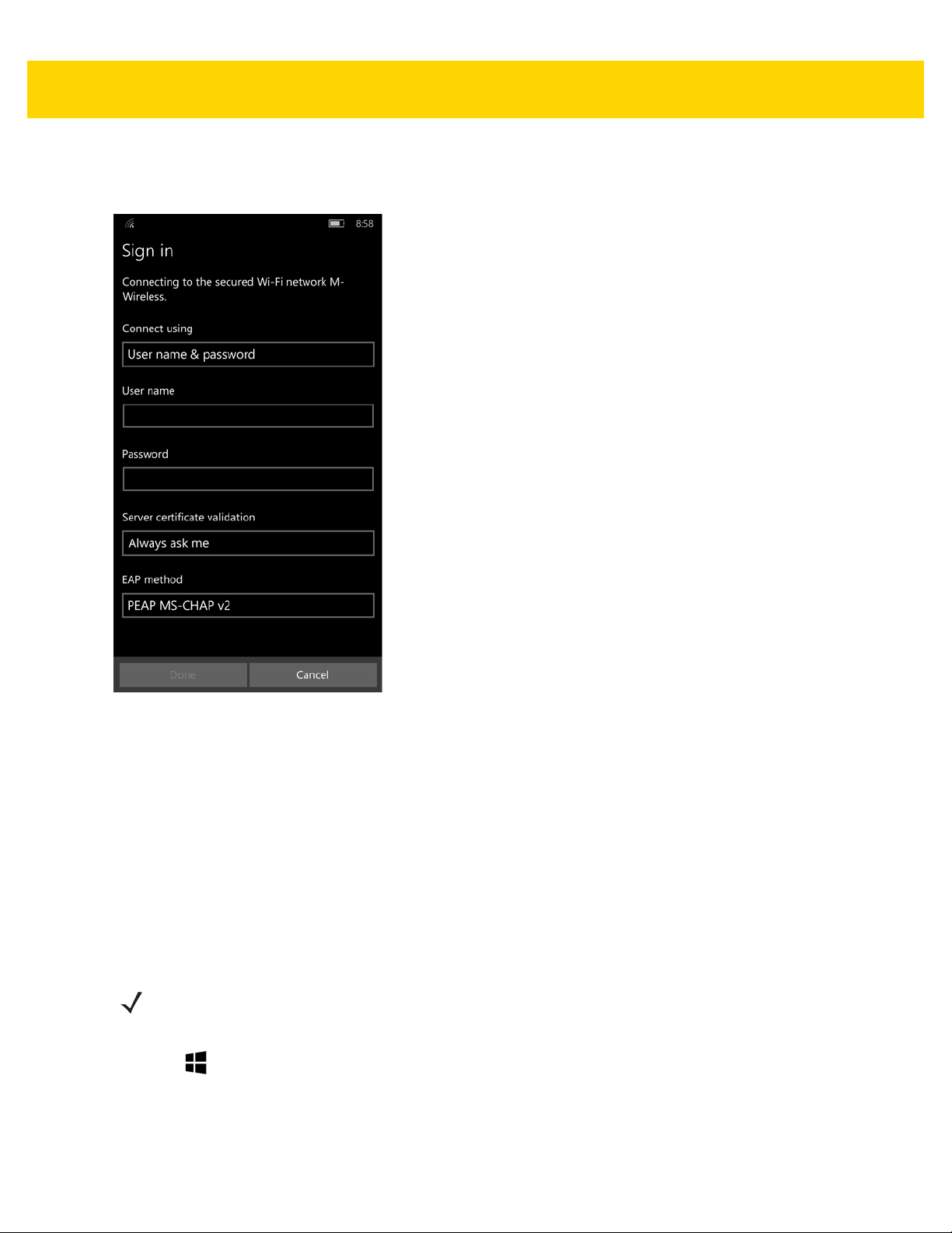
4. Scroll through the list and select the desired WLAN network.
5. Touch the desired network.
WLAN Configuration 3 - 3
Figure 3-2 WLAN Network Security Dialog Box
6. Touch Connect using drop-down list and select User name & password.
7. In the User name text box, enter user name.
8. In the Password text box, enter the password.
9. Touch the Server certificate validation drop-down list and select one of the following:
a. None
b. Always ask me
c. Certificate authority.
10. Touch the EAP method drop-down list and select PEAP MS-CHAPv2 or TTLS.
11. Touch Done.
NOTE By default, the network Proxy is set to None and the IP settings is set to DHCP. See Configuring for a
Proxy Server on page 3-5 for setting connection to a proxy server and see Configuring the Device to Use
a Static IP Address on page 3-6 for setting the device to use a static IP address.
12. Touch .
Certificate
To set up a Wi-Fi network using a certificate:

3 - 4 TC70x Integrator Guide
1. First install a certificate. See Security chapter.
2. Swipe down from the top of the screen, and touch All settings > Network & wireless > Wi-Fi.
3. Touch the Wi-Fi networking switch to turn on the Wi-Fi radio.
4. The device searches for WLANs in the area and lists them on the screen.
5. Scroll through the list and select the desired WLAN network.
6. Touch the desired network.
Figure 3-3 WLAN Network Security Dialog Box
7. Touch Connect using drop-down list and select Certificate.
8. Touch the Server certificate validation drop-down list and select one of the following:
a. None
b. Always ask me
c. Certificate authority.
9. Touch the EAP method drop-down list and select TLS or TTLS.
10. Touch Done.
NOTE By default, the network Proxy is set to None and the IP settings is set to DHCP. See Configuring for a
Proxy Server on page 3-5 for setting connection to a proxy server and see Configuring the Device to Use
a Static IP Address on page 3-6 for setting the device to use a static IP address.
11. Touch .

WLAN Configuration 3 - 5
Manually Adding a Wi-Fi Network
Manually add a Wi-Fi network if the network does not broadcast its name (SSID) or to add a Wi-Fi network when
out of range.
1. Swipe down from the top of the screen, and touch All settings > Network & wireless > Wi-Fi.
2. Scroll down and touch Manage button.
Figure 3-4 Add a Network
3. Touch . The Add ne t wo r k screen appears.
4. In the Network name field, enter the name of the Wi-Fi network.
5. Touch Add.
Configuring for a Proxy Server
A proxy server is a server that acts as an intermediary for requests from clients seeking resources from other
servers. A client connects to the proxy server, requesting some service, such as a file, connection, web page, or
other resource, available from a different server. The proxy server evaluates the request accor ding to its filtering
rules. For example, it may filter traffic by IP address or protocol. If the request is validated by the filter, the proxy
provides the resource by connecting to the relevant server and requesting the service on behalf of the client.
It is important for enterprise customers to be ab le to set up secu re computing environm ents within their companies,
and proxy configuration is an essential part of doing that. Proxy configuration acts as a security barrier ensuring
that the proxy server monitors all traffic between the Internet and the intranet. This is normally an integral part of
security enforcement in corporate firewalls within intranets.

3 - 6 TC70x Integrator Guide
1. Swipe down from the top of the screen, and touch All settings > Network & wireless > Wi-Fi.
2. Touch and hold a network name until the menu appears.
3. Touch Edit.
Figure 3-5 Proxy Settings
4. In the Proxy drop-down menu, select Manual setup.
5. In the Address text box, enter the address of the proxy server.
6. In the Port text box, enter the port number for the proxy server.
7. If the proxy server requires a log in, touch the Sign into proxy switch.
a. In the User name text box, enter the username.
b. In the Password text box, enter the password.
8. Touch .
9. Touch .
Configuring the Device to Use a Static IP Address
By default, the device is configured to use Dynamic Host Configuration Protocol (DHCP) to assign an Internet
protocol (IP) address when connecting to a wireless network. To configure the device to connect to a network using
a static IP address:
1. In the Wi-Fi window, scroll down and select Static IP button.
2. Touch the Configure network settings manually switch.

WLAN Configuration 3 - 7
Figure 3-6 Static IP Settings
3. In the IP address text box, enter an IP address for the device.
4. In the Subnet mask text box, enter the subnet mask number.
5. If required, in the Default Gateway text box, enter a gateway address for the device.
6. If required, in the Network prefix length text box, enter a the prefix length.
7. If required, in the DNS text box, enter a Domain Name System (DNS) address.
8. Touch Done.
9. Touch .
10. Reboot the device.

3 - 8 TC70x Integrator Guide

CHAPTER 4 USB COMMUNICATION
Introduction
This chapter provides information for transferring files between the device and a host computer.
Connecting to a Host Computer via USB
Connect the TC70x to a host computer using the USB Charging cable to transfer files between the TC70x and the
host computer.
When connecting the TC70x to a host computer, follow the host computer’s instructions for connecting and
disconnecting USB devices, to avoid damaging or corrupting files.
1. Connect the USB Charge cable to the TC70x and then to the host computer. The USB dialog box appears.
Figure 4-1 USB Data Connection Dialog Box
2. Touch Yes.
3. On the host computer, open a file explorer application.
4. Locate the Windows phone as a portable device.
5. Open the SD card or the Phone folder.
6. Copy or delete files as required.

4 - 2 TC70x Integrator Guide
Disconnect from the Host Computer
CAUTION Carefully follow the host computer’s instructions to unmount the microSD card and disconnect USB
devices correctly to avoid losing information.
7. On the host computer, unmount the device.
8. Remove the USB Charging cable from the device.

CHAPTER 5 SETTINGS
Introduction
This chapter describes settings available for configuring the device.
System
Display - Controls setting for brightness, screen rotation, and text size.
Notifications & Actions - Controls quick action items and the type of notifications that appear on the Action
Center.
Phone - Not applicable.
Messaging - Not applicable.
Battery saver - Displays the current battery charge level and controls battery saver mode.
Storage - Displays the amount of space available of the device and SD card (if installed). Controls where data is
saved by default.
Device encryption - Enables device encryption.
Offline maps - Allows user to download maps for access when no internet access is available.
About - Displays device information and allows user to change the name of the device.
Devices
Default camera - Use to set the default camera application.
Bluetooth - Use to configure Bluetooth radio. Refer to the TC70x User Guide for Windows 10 IoT Mobile
Enterprise.
NFC - Use to configure NFC radio. Refer to the TC70x User Guide for Windows 10 IoT Mobile Enterprise.
Mouse - Use to set primary mouse button.

5 - 2 TC70x Integrator Guide
USB - Use to control the TC70x USB connection.
Network & Wireless
Data Usage - Displays the amount of data transferred over Wi-Fi.
Wi-Fi - Use to configure Wi-Fi radio. See Chapter 3, WLAN Configuration for more information.
Airplane Mode - Use to turn off all radios.
VPN - Use to configure connection to a VPN network.
Personalization
Start - Use to configure the Start screen.
Colors - Use to set the color scheme for Windows environment.
Sounds - Use to configure when a sounds plays.
Lock Screen - Use to configure the lock screen.
Accounts
Use the Accounts settings to add, remove, and manage accounts. Use these settings to control how applications
send, receive, and sync data on their own schedules, and whether applications can synchronize user data
automatically. Applications may also have their own settings to control how they synchronize data; see the
documentation for those applications for details.
Your email and accounts - Use to set up Windows email accounts and other email accounts.
Sign-in options - Use to create a PIN that is required when unlocking the device.
Work access - Use to set up access to work network and enroll in a device management application.
Sync your settings - Use to sync Windows settings with other devices.
Kid’s corner - Not applicable.
Apps Corner - Allows user to give people access to apps on the device.
Provisioning - Use to install a provisioning package. See Chapter 9, Provisioning.
Time & language
Date & Time - Use to set the date and time on the device.
Language - Use to add a language feature to the device. Internet access required. See Language Usage on page
5-4.
Region - Use to set the country and region that the device is located.
Keyboard - Use to add additional language keyboards.

Speech - Use to download and install additional speech languages.
Ease of Access
Narrator - Use to set the device to read aloud text and controls. Once enabled, choose a voice (male or female)
and adjust the narrator's speed and pitch.
Magnifier - Use to enable screen magnification. When enabled, double touch the screen with two fingers to
magnify the screen. Use two fingers to more the screen. Double touch the screen with two fingers to return to
normal magnification.
High Contrast - Use to enable high contrast to make it easier for people with visual impairments to see different
items on the screen.
Closed caption - Use to control how closed captions appear in Windows apps. Change the color, transparency,
style, size, background color, background transparency, window color, and window transparency of the captions.
More Options - Adjust the size of the text displayed on the screen.
Settings 5 - 3
Privacy
Location - Use to allow apps to request device location and location history.
Camera - Use to allow apps to access the camera.
Microphone - Use to allow apps to access the microphone.
Motion - Use to allow apps to use motion data.
Speech, inking & typing - To improve the device’s ability to correctly recognize your pronunciation and handwriting,
Microsoft collects speech, inking, and typing information when you interact with the device by speaking, writing, or
typing. If you have allowed Cortana to do so, Microsoft also collects information about your Calendar and People
(also known as contacts) to help personalize your experience and helps Cortana better recognize people, events,
places, and music when you dictate messages or documents.
Account info - Use to allow apps to access account information.
Contacts - Use to allow apps to access contacts.
Calendar - Use to allow apps to access the calendar.
Call History - Use to allow apps to access call history.
Email - Use to allow apps to access emails.
Messaging - Use to allow apps to access test messages.
Radios - Use to allow apps to use the device’s radios.
Background apps - Choose which apps can receive information, send notifications and stay up-to-date when not in
use.
Accessory Apps - Use to control notifications to and from accessory apps.
Advertising ID - Use to allow apps to use the device’s advertising ID.

5 - 4 TC70x Integrator Guide
Other Devices - Use to allow apps to share and sync information with wireless devices that do not pair with the
device.
Feedback & diagnostics - Use to set how often Microsoft asks for feedb ack and the am ount of Windows diagnostic
and usage data sent to Microsoft from the device.
Update & Security
Phone update - Check for system updates.
Backup - Controls backup of data to OneDrive.
Find My Phone - Use to set up and control locking and finding lost devices.
For developers - Use for developer use only.
Extras
Zebra TC700J Settings - Set device hardware beep and touch configuration. See TC70x Touch Computer User
Guide with Windows 10 IoT Mobile Enterprise.
Zebra TC700J System Info - Display system information:
Language Usage
Use the Language settings to change the language that display for the text and including wor ds added to its
dictionary.
Changing the Language Setting
To add several writing languages to the keyboard and switch between the languages when writing.
1. Swipe down from the top of the screen, and touch All settings > Time & language > Keyboard.
2. Touch Add keyboards.
3. In the list, select the languages.
4. Touch .
5. If the language package is not on the device, the device tries to download the language package.
6. Touch Yes.
To remove a language, touch and hold the language you want to remove, and touch Remove.
To switch between the languages when writing, swipe left or right on the space bar un til the language a ppears. The
keyboard layout and word suggestions change according to the language selected.

Storage
The TC70x has internal storage and optional external storage. The internal and external storage content can be
viewed and files copied to and from when the TC70x is connected to a host computer.
1. Swipe down from the top of the screen, and touch All settings > System > Storage.
Settings 5 - 5
Figure 5-1 Storage Screen
The amount of space available and used is listed for each drive.
To uch to view detailed information.

5 - 6 TC70x Integrator Guide
Figure 5-2 Device Usage Screen

CHAPTER 6 SCANNER PROFILES
Introduction
This chapter describes how to use the Zebra Scannin g Pro f ile application to create and edit profile parameters
such as decoder parameters, scan parameters and reader parameters. Use the profiles to enable specific
scanning parameters in scanning applications.
Note that default parameters are not be listed in the profile settings application.
Application Installation
Download the Zebra Scanner Profile application from the Zebra Support & Downloads web site. Go to:
www.zebra.com/support.
To install the application, see Application Installation on page 10-1.
Profiles
A profile contains information on how the scanner behaves within different applications. Using profiles, an
application can have a specific configurations. For example, each application can have a profile which outputs
scanned data in the required format when that application comes to the foreground. The application can be
configured to process the same set of captured data differently based on the requirements of each application.
Creating a New Profile
To create a new profile:
1. Touch +.

6 - 2 TC70x Integrator Guide
Figure 6-1 Create New Profile Dialog Box
2. In the Create new Profile dialog box, enter a name for the new profile.
It is recommended that profile names be unique and made up of only alpha-numeric characters (A-Z, a-z, 0-9).
The filename cannot contain: / \ : * ? “ < > | or space.
3. Touch Set.
The new profile name appears in the Profiles list.
Figure 6-2 Profile List
Configuring a Profile
To configure a profile:
1. Touch the profile name. The Profile screen appears.

Scanner Profiles 6 - 3
Figure 6-3 Profiles Screen
2. Touch Decoders. The Decoders screen appears.

6 - 4 TC70x Integrator Guide
Figure 6-4 Decoders
3. Select a decoder type to configure for this profile. See Decoders on page 6-7 for detailed information on each
decoder.
4. Touch to return to the Profile screen.
5. Touch Reader Params to configure the scanner parameters. The Reader Params screen appears.

Scanner Profiles 6 - 5
Figure 6-5 Reader Parameters
6. Select all the parameters for this profile and configure. See Reader Params on page 6-13 for detailed
information on each parameter.
7. Touch to return to the Profile screen.
8. Touch Scan Params to configure the scanner parameters. The Scan Params screen appears.

6 - 6 TC70x Integrator Guide
Figure 6-6 Scan Parameters
9. Select all the parameters for this profile and configure. See Scan Params on page 6-13 for detailed information
on each parameter .
10. Touch to save the profile information. A profile file is created in the Documents folder.
The scanner driver is updated.
Using a Profile
To use the profile, the application has to call SetActiveProfile with newly created profile name as a parameter.
In an application, if the user selects the supported profiles, the newly added profile displays along with the list of
default profiles.
Deleting a Profile
To delete a profile:
1. Touch and hold on the profile name until a menu appears.
2. Touch Remove.
The profile is remove from the device and from the scanner driver.
 Loading...