

Zebra TC52x and TC52ax Touch Computer TC52ax/TC52ax-HC Touch Computer Product Reference Guide for Android 11 (en)

TC52ax/TC52ax-HC
Touch Computer
Product Reference
Guide
for Android™ 11
MN-004162-03EN Rev. A

ZEBRA and the stylized Zebra head are trademarks of Zebra Technologies Corporation, registered in many
jurisdictions worldwide. Google, Android, Google Play and other marks are trademarks of Google LLC. All
other trademarks are the property of their respective owners. ©2021 Zebra Technologies Corporation and/or
its affiliates. All rights reserved.
COPYRIGHTS & TRADEMARKS: For complete copyright and trademark information, go to
zebra.com/copyright
.
WARRANTY: For complete warranty information, go to zebra.com/warranty
END USER LICENSE AGREEMENT: For complete EULA information, go to zebra.com/eula
Terms of Use
• Proprietary Statement
This manual contains proprietary information of Zebra Technologies Corporation and its subsidiaries
(“Zebra Technologies”). It is intended solely for the information and use of parties operating and maintaining
the equipment described herein. Such proprietary information may not be used, reproduced, or disclosed to
any other parties for any other purpose without the express, written permission of Zebra Technologies.
• Product Improvements
Continuous improvement of products is a policy of Zebra Technologies. All specifications and designs are
subject to change without notice.
• Liability Disclaimer
Zebra Technologies takes steps to ensure that its published Engineering specifications and manuals are
correct; however, errors do occur. Zebra Technologies reserves the right to correct any such errors and
disclaims liability resulting therefrom.
• Limitation of Liability
In no event shall Zebra Technologies or anyone else involved in the creation, production, or delivery of the
accompanying product (including hardware and software) be liable for any damages whatsoever (including,
without limitation, consequential damages including loss of business profits, business interruption, or loss of
business information) arising out of the use of, the results of use of, or inability to use such product, even if
Zebra Technologies has been advised of the possibility of such damages. Some jurisdictions do not allow
the exclusion or limitation of incidental or consequential damages, so the above limitation or exclusion may
not apply to you.
.
.
2

Table of Contents
Terms of Use................................................................................................................... 2
About This Guide.............................................................................................................................. 12
Configurations............................................................................................................... 12
Notational Conventions................................................................................................. 12
Icon Conventions .......................................................................................................... 13
Service Information ....................................................................................................... 13
Determining Software Versions..................................................................................... 14
Determining the Serial Number..................................................................................... 14
Getting Started.................................................................................................................................. 15
Introduction ................................................................................................................... 15
Unpacking ..................................................................................................................... 15
TC52ax Standard Features........................................................................................... 16
TC52ax Advanced Range Features.............................................................................. 18
Setting Up the Device ................................................................................................... 20
Installing a microSD Card....................................................................................... 20
Installing the Battery ............................................................................................... 21
Charging the Battery............................................................................................... 22
Charging Indicators ................................................................................................ 23
Replacing the TC52ax Battery ...................................................................................... 23
Replacing the microSD Card......................................................................................... 24
Using the Device............................................................................................................................... 26
Home Screen ................................................................................................................ 26
Setting Home Screen Rotation ............................................................................... 27
Status Bar............................................................................................................... 27
Notification Icons.............................................................................................. 27
Status Icons ..................................................................................................... 28
3

Table of Contents
Managing Notifications ........................................................................................... 29
Opening the Quick Access Panel ........................................................................... 30
Quick Access Panel Icons................................................................................ 31
Editing Icons on the Quick Settings Bar ................................................................. 32
Battery Management..................................................................................................... 32
Checking Battery Status ......................................................................................... 32
Monitoring Battery Usage ....................................................................................... 32
Low Battery Notification.......................................................................................... 33
Using the Rechargeable Li-Ion Battery with BLE Beacon............................................. 33
Waking the Device ........................................................................................................ 33
USB Communication..................................................................................................... 33
Transferring Files.................................................................................................... 34
Transferring Photos ................................................................................................ 34
Disconnect from the Host Computer ...................................................................... 34
Settings.............................................................................................................................................. 35
Accessing Settings........................................................................................................ 35
Display Settings ............................................................................................................ 35
Setting the Screen Brightness Manually................................................................. 35
Setting the Screen Brightness Automatically.......................................................... 35
Setting Night Light .................................................................................................. 35
Setting Screen Rotation.......................................................................................... 36
Setting Screen Timeout .......................................................................................... 36
Lock Screen............................................................................................................ 36
Setting Font Size .................................................................................................... 37
Notification LED Brightness Level .......................................................................... 37
Touch Panel Mode ................................................................................................. 37
Setting the Date and Time ............................................................................................ 38
General Sound Setting.................................................................................................. 38
Sound Options........................................................................................................ 38
Setting Wake-Up Sources ...................................................................................... 39
Remapping a Button ..................................................................................................... 39
Remappable Keys......................................................................................................... 40
Keyboards..................................................................................................................... 40
Keyboard Configuration.......................................................................................... 40
Enabling Keyboards ......................................................................................... 40
Switching Between Keyboards......................................................................... 40
Using the Android and Gboard Keyboards............................................................. 41
Edit Text ........................................................................................................... 41
Entering Numbers, Symbols, and Special Characters ..................................... 41
Using the Enterprise Keyboard............................................................................... 41
4

Table of Contents
Numeric Tab..................................................................................................... 41
Alpha Tab......................................................................................................... 41
Additional Character Tab ................................................................................. 41
Scan Tab.......................................................................................................... 41
Language Usage........................................................................................................... 42
Changing the Language Setting ............................................................................. 42
Adding Words to the Dictionary .............................................................................. 42
Notifications................................................................................................................... 42
Setting App Notifications ........................................................................................ 42
Viewing Notification Settings for All Apps ........................................................ 43
Controlling Lock Screen Notifications .............................................................. 43
Blink Light......................................................................................................... 44
Applications ...................................................................................................................................... 45
Accessing Apps............................................................................................................. 46
Switching Between Recent Apps............................................................................ 46
Battery Manager............................................................................................................ 47
Opening Battery Manager ...................................................................................... 47
Battery Manager Information Tab........................................................................... 47
Battery Manager Swap Tab.................................................................................... 48
Camera ......................................................................................................................... 49
Taking Photos......................................................................................................... 49
Recording Videos ................................................................................................... 50
Camera Settings..................................................................................................... 51
DataWedge Demonstration........................................................................................... 52
Scanner Selection .................................................................................................. 52
PTT Express Voice Client ............................................................................................. 53
PTT Express User Interface ................................................................................... 53
PTT Audible Indicator ............................................................................................. 54
PTT Notification Icons ............................................................................................ 54
Enabling PTT Communication................................................................................ 55
Selecting a Talk Group ........................................................................................... 55
PTT Communication............................................................................................... 55
Responding with a Private Response .............................................................. 56
Disabling PTT Communication ............................................................................... 56
RxLogger....................................................................................................................... 57
RxLogger Configuration.......................................................................................... 57
Configuration File ................................................................................................... 57
Enabling Logging.................................................................................................... 57
Disabling Logging ................................................................................................... 57
Extracting Log Files ................................................................................................ 57
Backing Up ............................................................................................................. 57
5

Table of Contents
RxLogger Utility ...................................................................................................... 58
Initiating the Main Chat Head........................................................................... 58
Removing the Main Chat Head ........................................................................ 58
Viewing Logs.................................................................................................... 58
Removing a Sub Chat Head Icon..................................................................... 58
Backing Up In Overlay View............................................................................. 58
Wireless............................................................................................................................................. 59
Wireless Local Area Networks ...................................................................................... 59
Connecting to a Wi-Fi Network............................................................................... 60
Wi-Fi Version.................................................................................................... 60
Removing a Wi-Fi Network..................................................................................... 60
WLAN Configuration ..................................................................................................... 60
Configuring a Secure Wi-Fi Network ...................................................................... 60
Manually Adding a Wi-Fi Network .......................................................................... 61
Configuring for a Proxy Server ............................................................................... 63
Configuring the Device to Use a Static IP Address ................................................ 63
Wi-Fi Preferences................................................................................................... 64
Additional Wi-Fi Settings ........................................................................................ 64
Wi-Fi Direct............................................................................................................. 64
Bluetooth....................................................................................................................... 65
Adaptive Frequency Hopping ................................................................................. 65
Security................................................................................................................... 66
Bluetooth Profiles ................................................................................................... 66
Bluetooth Power States .......................................................................................... 67
Bluetooth Radio Power........................................................................................... 67
Enabling Bluetooth ........................................................................................... 67
Disabling Bluetooth .......................................................................................... 67
Discovering Bluetooth Device(s) ............................................................................ 68
Changing the Bluetooth Name ............................................................................... 68
Connecting to a Bluetooth Device .......................................................................... 68
Selecting Profiles on the Bluetooth Device............................................................. 68
Unpairing a Bluetooth Device ................................................................................. 69
Cast............................................................................................................................... 69
Near Field Communications.......................................................................................... 69
Reading NFC Cards ............................................................................................... 70
Enterprise NFC Settings......................................................................................... 70
Accessories....................................................................................................................................... 72
Battery Charging ........................................................................................................... 75
Main Battery Charging............................................................................................ 75
6

Table of Contents
Spare Battery Charging .......................................................................................... 76
Charging Temperature ........................................................................................... 76
1-Slot USB Charge Cradle............................................................................................ 77
Setup ...................................................................................................................... 78
Charging the Device ............................................................................................... 78
Inserting a Device with the Rugged Boot into Cradle ............................................. 79
Zebra Workstation Cradle ............................................................................................. 80
Setup ...................................................................................................................... 82
Ethernet Setup........................................................................................................ 83
Scanner Setup........................................................................................................ 83
Security................................................................................................................... 83
Using the Workstation Cradle................................................................................. 84
Changing Monitor Resolution ................................................................................. 84
Charging the Device ............................................................................................... 84
Inserting a TC52ax with the Rugged Boot into the Cradle............................................ 84
2-Slot USB/Ethernet Cradle .......................................................................................... 86
Setup ...................................................................................................................... 87
Ethernet Settings.............................................................................................. 87
Configuring Ethernet Proxy Settings ................................................................ 87
Configuring Ethernet Static IP Address............................................................ 88
4-Slot Charge Only Cradle with Battery Charger .......................................................... 92
Setup ...................................................................................................................... 93
Charging the Device ............................................................................................... 93
Inserting a TC52ax with the Rugged Boot into the Cradle ..................................... 94
Charging the Spare Battery .................................................................................... 94
5-Slot Charge Only Cradle............................................................................................ 96
Setup ...................................................................................................................... 97
Charging the Device ............................................................................................... 97
Inserting a Device with the Rugged Boot into the Cradle ....................................... 98
5-Slot Ethernet Cradle................................................................................................... 99
Setup .................................................................................................................... 100
Daisy-chaining Ethernet Cradles .......................................................................... 100
Ethernet Settings .................................................................................................. 101
Configuring Ethernet Proxy Settings .............................................................. 101
Configuring Ethernet Static IP Address.......................................................... 102
Charging the Device ............................................................................................. 102
Inserting a TC52ax with the Rugged Boot into Cradle ......................................... 103
Establishing Ethernet Connection .................................................................. 103
LED Indicators ...................................................................................................... 103
4-Slot Battery Charger ................................................................................................ 104
Setup .................................................................................................................... 104
Single Charger Setup..................................................................................... 104
7

Table of Contents
Two Charger Setup ........................................................................................ 105
Charging Spare Batteries ..................................................................................... 106
Rugged Boot ............................................................................................................... 108
Installation ............................................................................................................ 108
Installing Plastic Stylus ......................................................................................... 109
Charging with Cradles .......................................................................................... 110
Basic Hand Strap Kit................................................................................................... 112
Installation ............................................................................................................ 112
Removal ............................................................................................................... 113
2.5 mm Audio Adapter ................................................................................................ 115
3.5 mm Audio Adapter ................................................................................................ 116
Rugged Charge/USB Cable........................................................................................ 117
Connecting Rugged Charge/USB Cable to Device .............................................. 117
Connecting to TC5ax with Rugged Boot .............................................................. 118
USB Communication ............................................................................................ 119
Charging the Device ............................................................................................. 119
Disconnecting the Rugged Charge/USB Cable.................................................... 120
Trigger Handle ............................................................................................................ 121
Installing the Rugged Boot ................................................................................... 121
Installing the Optional Lanyard ............................................................................. 123
Inserting the Device into the Trigger Handle ........................................................ 124
Removing the Device from the Trigger Handle .................................................... 124
Installing the Extended Rugged Boot.......................................................................... 126
Removal ............................................................................................................... 127
Power Supply.............................................................................................................. 128
5-Slot Cradle Rack Installation.................................................................................... 129
4-Slot Battery Chargers Rack Installation ................................................................... 132
Rack Mount Installation............................................................................................... 135
Wall Installation........................................................................................................... 138
Bottom Tray Assembly ......................................................................................... 138
Bracket Wall Mounting.......................................................................................... 138
Data Capture ................................................................................................................................... 140
Imaging ....................................................................................................................... 140
Digital Camera ............................................................................................................ 140
Linear Imager.............................................................................................................. 141
Operational Modes ............................................................................................... 141
RS507/RS507X Hands-Free Imager........................................................................... 142
RS5100 Ring Scanner ................................................................................................ 142
RS6000 Bluetooth Ring Scanner ................................................................................ 142
DS3678 Digital Scanner.............................................................................................. 143
8

Table of Contents
LI3678 Linear Scanner................................................................................................ 143
DS2278 Digital Scanner.............................................................................................. 144
DS8178 Scanner......................................................................................................... 144
Scanning Considerations ............................................................................................ 144
Scanning with Internal Imager..................................................................................... 145
Scanning with Internal Camera................................................................................... 146
Scanning with RS507/RS507X Hands-Free Imager ................................................... 148
Scanning with RS6000 Bluetooth Ring Scanner......................................................... 149
Scanning with RS5100 Ring Scanner......................................................................... 150
Scanning with the DS3678 Bluetooth Scanner ........................................................... 151
Scanning with LI3678 Linear Imager........................................................................... 152
Scanning with DS2278 Digital Scanner ...................................................................... 153
Scanning with DS8178 Digital Scanner ...................................................................... 154
Pairing the Bluetooth Ring Scanner............................................................................ 155
Pairing Using Near Field Communication ................................................................... 155
Pairing in HID Mode Using Near Field Communication........................................ 156
Pairing Using Simple Serial Interface ................................................................... 157
Pairing Using Bluetooth Human Interface Device ................................................ 158
Pairing a Bluetooth Scanner ....................................................................................... 159
Pairing Using Simple Serial Interface ................................................................... 159
Pairing Using Bluetooth Human Interface Device ................................................ 159
DataWedge ................................................................................................................. 160
Enabling DataWedge............................................................................................ 160
Disabling DataWedge........................................................................................... 160
Supported Decoders............................................................................................. 161
Application Deployment................................................................................................................. 164
Security ....................................................................................................................... 164
Secure Certificates...................................................................................................... 164
Installing a Secure Certificate ..................................................................................... 164
Configuring Credential Storage Settings .............................................................. 165
Development Tools ..................................................................................................... 165
Android Application Development ........................................................................ 165
Development Workstation .............................................................................. 165
Enabling Developer Options .......................................................................... 165
EMDK for Android................................................................................................. 166
StageNow ............................................................................................................. 166
GMS Restricted........................................................................................................... 166
ADB USB Setup.......................................................................................................... 166
Enabling USB Debugging..................................................................................... 166
Entering Android Recovery Manually ................................................................... 167
9

Table of Contents
Application Installation ................................................................................................ 167
Installing Applications Using the USB Connection ............................................... 168
Installing Applications Using the Android Debug Bridge ...................................... 168
Installing Applications Using the Wireless Android Debug Bridge........................ 169
Installing Applications Using a microSD Card ...................................................... 170
Uninstalling an Application ................................................................................... 170
Performing a System Update...................................................................................... 170
Downloading the System Update Package .......................................................... 171
Performing a System Update Using microSD Card.............................................. 171
Performing a System Update Using ADB............................................................. 171
Performing a System Update Using Wireless ADB .............................................. 172
Verifying System Update Installation.................................................................... 173
Enterprise Reset ......................................................................................................... 173
Performing an Enterprise Reset From Device Settings........................................ 174
Downloading the Enterprise Reset Package ........................................................ 174
Performing an Enterprise Reset Using microSD Card ......................................... 174
Performing an Enterprise Reset Using ADB......................................................... 174
Performing an Enterprise Reset Using Wireless ADB.......................................... 175
Performing a Factory Reset ........................................................................................ 176
Downloading the Factory Reset Package ............................................................ 176
Performing a Factory Reset Using microSD Card................................................ 177
Performing a Factory Reset Using ADB ............................................................... 177
Performing a Factory Reset Using Wireless ADB ................................................ 178
Storage........................................................................................................................ 179
Random Access Memory ..................................................................................... 179
Viewing Memory............................................................................................. 180
Internal Storage .................................................................................................... 180
Viewing Internal Storage ................................................................................ 180
External Storage................................................................................................... 180
Viewing External Storage............................................................................... 180
Formatting a microSD Card ........................................................................... 180
Formatting a microSD Card as Internal Memory............................................ 181
Enterprise Folder .................................................................................................. 181
Managing Apps ........................................................................................................... 181
App Details ........................................................................................................... 181
Managing Downloads.................................................................................................. 182
Maintenance and Troubleshooting ............................................................................................... 183
Maintaining the Device................................................................................................ 183
Display Best Practices ................................................................................................ 183
Image Retention ................................................................................................... 183
10

Table of Contents
Best Practices for Enterprise Mobile Computing Devices Operating in Hot Environments
and Direct Sunlight...................................................................................................... 184
Battery Safety Guidelines ..................................................................................... 184
Cleaning Instructions................................................................................................... 185
Cleaning and Disinfecting Guidelines................................................................... 185
Approved Cleaning and Disinfectant Agents ........................................................ 185
Battery Connector and Locating Magnet Cleaning............................................... 185
Cleaning Cradle Connectors....................................................................................... 186
Troubleshooting .......................................................................................................... 188
Resetting the Device ............................................................................................ 188
Performing a Soft Reset................................................................................. 188
Performing a Hard Reset ............................................................................... 188
TC52ax ................................................................................................................. 188
1-Slot Charge Only Cradle ................................................................................... 191
Workstation Docking Cradle ................................................................................. 191
2-Slot USB/Ethernet Cradle.................................................................................. 192
4-Slot Charge Only Cradle with Battery Charger Troubleshooting....................... 193
5-Slot Charge Only Cradle Troubleshooting......................................................... 193
5-Slot Ethernet Cradle Troubleshooting ............................................................... 194
4-Slot Battery Charger Troubleshooting ............................................................... 194
Technical Specifications................................................................................................................ 196
TC52ax Standard (SE4720) Decode Distances ................................................... 196
TC52ax Advanced Range (SE5500) Decode Distances ...................................... 198
Interface Connector Pin-Outs ............................................................................... 199
1-Slot Charge Only Cradle Technical Specifications............................................ 199
Workstation Docking Cradle Technical Specifications ......................................... 200
2-Slot USB/Ethernet Cradle Technical Specifications .......................................... 200
4-Slot Charge Only Cradle with Battery Charger Technical Specifications .......... 201
5-Slot Charge Only Cradle Technical Specifications............................................ 201
5-Slot Ethernet Cradle Technical Specifications .................................................. 202
4-Slot Battery Charger Technical Specifications .................................................. 202
Trigger Handle Technical Specifications .............................................................. 203
Rugged Charge/USB Cable Technical Specifications.......................................... 203
11

About This Guide
This guide provides information about setting up and using the TC52ax touch computer. Some screens shown
in this guide may differ from the actual screens shown on the device.
Configurations
This guide covers the following configurations:
Table 1 Configurations
Configuration Description Display Memory
TC52ax Standard
(with
PowerPrecision+
Standard Battery)
TC52ax Standard
(with Rechargeable
Li-Ion Battery with
BLE Beacon)
TC52ax Advanced
Range (with SE55
Imager and
PowerPrecision+
Standard Battery)
TC52ax Advanced
Range (with SE55
Imager and
Rechargeable
Li-Ion Battery with
BLE Beacon)
Wi-Fi 6, Standard 7 pin I/O
Bottom Comm. I/O Rear,
PowerPrecision+ Standard
Battery
Wi-Fi 6, Standard 7 pin I/O
Bottom, Comm. I/O Rear,
Rechargeable Li-Ion Battery
with BLE Beacon
Wi-Fi 6, Standard 7 pin I/O
Bottom Comm. I/O Rear,
PowerPrecision+ Standard
Battery
Wi-Fi 6, Standard 7 pin I/O
Bottom, Comm. I/O Rear,
Rechargeable Li-Ion Battery
with BLE Beacon
5.0” Full
High
Definition
(1080 x
1920) LCD
5.0” Full
High
Definition
(1080 x
1920) LCD
5.0” Full
High
Definition
(1080 x
1920) LCD
5.0” Full
High
Definition
(1080 x
1920) LCD
4 GB RAM /
64 GB UFS Flash
4 GB RAM /
64 GB UFS Flash
4 GB RAM /
64 GB UFS Flash
4 GB RAM /
64 GB UFS Flash
Data Capture
Options
2D imager
(SE4720) and
integrated NFC
2D imager
(SE-4720) and
integrated NFC
2D imager (SE55)
and integrated
NFC
2D imager (SE55)
and integrated
NFC
Operating System
Android-based,
Google ™ Mobile
Services (GMS) 11
Android-based,
Google ™ Mobile
Services (GMS) 11
Android-based,
Google ™ Mobile
Services (GMS) 11
Android-based,
Google ™ Mobile
Services (GMS) 11
12

Table 1 Configurations (Continued)
About This Guide
Configuration Description Display Memory
TC52ax Healthcare
with SE4720
Imager and
PowerPrecision+
Standard Battery)
TC52ax Healthcare
with SE4720
Imager and
Rechargeable
Li-Ion Battery with
BLE Beacon)
Wi-Fi 6, Standard 7 pin I/O
Bottom, Rear Red
Mechanical Button,
PowerPrecision+ Standard
Battery
Wi-Fi 6, Standard 7 pin I/O
Bottom, Rear Red
Mechanical Button,
Rechargeable Li-Ion Battery
with BLE Beacon
5.0” Full
High
Definition
(1080 x
1920) LCD
5.0” Full
High
Definition
(1080 x
1920) LCD
4 GB RAM /
64 GB UFS Flash
4 GB RAM /
64 GB UFS Flash
Notational Conventions
Notational conventions are used to highlight important information.
• Bold text is used to highlight the following:
• Dialog box, window and screen names
• Drop-down list and list box names
• Check box and radio button names
• Icons on a screen
Data Capture
Options
2D imager
(SE-4720) and
integrated NFC
2D imager
(SE-4720) and
integrated NFC
Operating System
Android-based,
Google ™ Mobile
Services (GMS) 11
Android-based,
Google ™ Mobile
Services (GMS) 11
• Key names on a keypad
• Button names on a screen.
• Bullets (•) indicate:
• Action items
• Lists of alternatives
• Lists of required steps that are not necessarily sequential.
• Sequential lists (for example, those that describe step-by-step procedures) appear as numbered lists.
Icon Conventions
The following icons are used throughout the document. The icons and their associated meanings are
described below.
NOTE: The text here indicates information that is supplemental for the user to know and that is not required to
complete a task.
IMPORTANT: The text here indicates information that is important for the user to know.
CAUTION: If the precaution is not heeded, the user could receive minor or moderate injury.
WARNING: If danger is not avoided, the user CAN be seriously injured or killed.
13

DANGER: If danger is not avoided, the user WILL be seriously injured or killed.
Service Information
If you have a problem with your equipment, contact Customer Support for your region. Contact information is
available at: zebra.com/support
When contacting support, please have the following information available:
• Serial number of the unit (found on manufacturing label)
• Model number or product name (found on manufacturing label)
• Software type and version number
• IMEI number
Customer Support responds to calls by email or telephone within the time limits set forth in support
agreements.
If the problem cannot be solved by Customer Support, the user may need to return the equipment for servicing
and will be given specific directions. We are not responsible for any damages incurred during shipment if the
approved shipping container is not used. Shipping the units improperly can possibly void the warranty.
Remove the SIM card and/or microSD card from the device before shipping for service.
About This Guide
.
If the device was purchased from a business partner, contact that business partner for support.
Determining Software Versions
Before contacting Customer Support, determine the current software version on your device.
1. Swipe down from the Status bar with two fingers to open the Quick Access panel, and then touch .
2. Touch Aboutphone.
3. Scroll to view the following information:
• Battery information
• SW components
• Legal information
• Model & hardware
• Android version
• Android security patch level
• Kernel version
• Build number
Determining the Serial Number
Before contacting Customer Support, determine the serial number of your device.
Touch About phone > Model & hardware > Serial number.
14

Getting Started
Introduction
This section provides information for getting the device up and running for the first time.
Unpacking
1. Carefully remove all protective material from the device and save the shipping container for later
storage and shipping.
2. Verify that the following were received:
• Touch computer
• >
15.48 Watt hours (typical) / > 4,150 mAh PowerPrecision+ Lithium-ion battery or
Rechargeable Li-Ion Battery with BLE Beacon
• Regulatory Guide.
3. Inspect the equipment for damage. If any equipment is missing or damaged, contact the Global
Customer Support center immediately.
4. Before using the device for the first time, remove the protective shipping film that covers the scan
window, display and camera window.
15

TC52ax Standard Features
CAUTION: The 7-pin interface connector at the bottom of the device is not removable. Trying to remove the
connector will cause damage to the device and can void warranty.
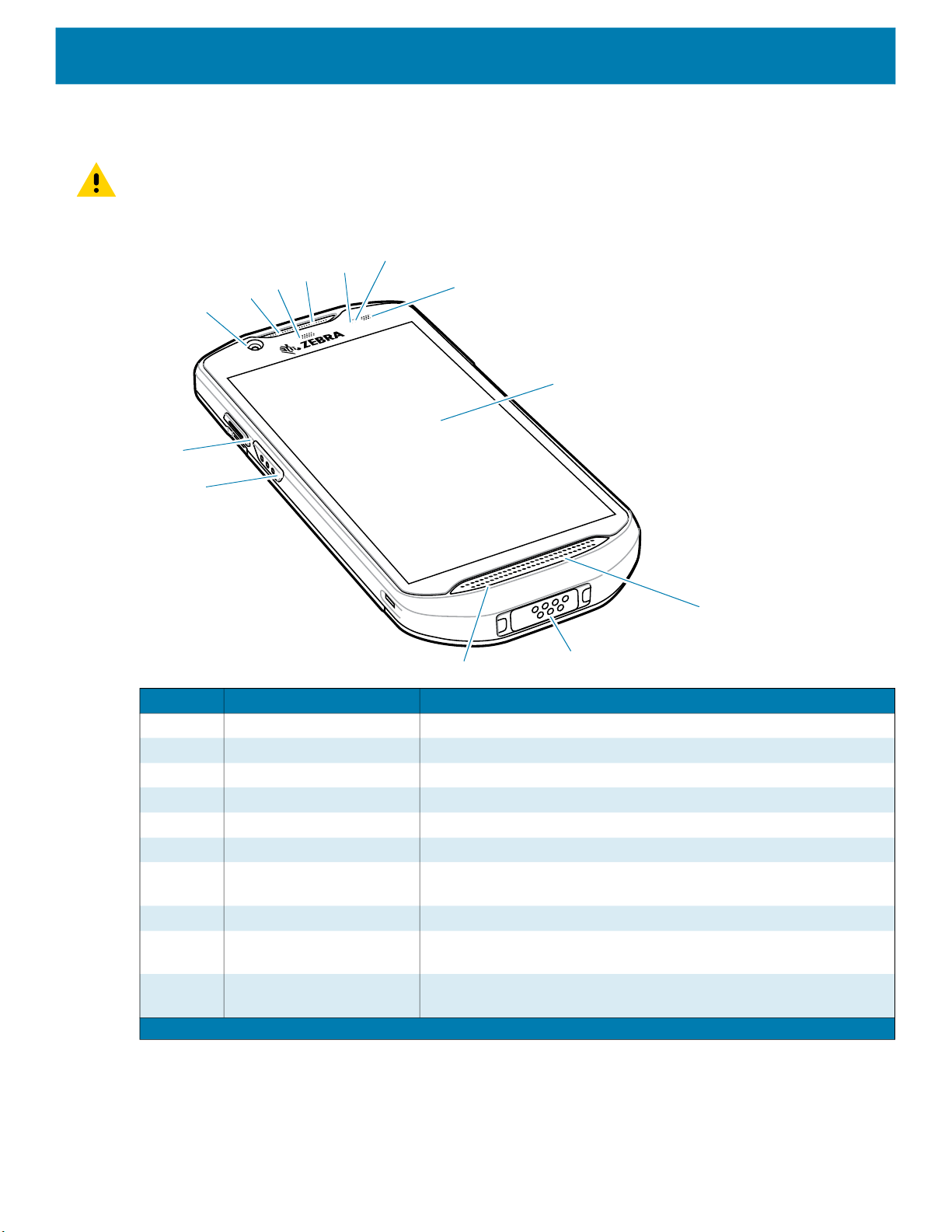
Figure 1 TC52ax Standard Front View
Getting Started
6
7
8
9
11
10
13
12
5
4
3
2
1
Number Item Function
1 5 MP Front camera Takes photos and videos.
2 Receiver Use for audio playback in Handset mode.
3 Data capture LED Indicates data capture status.
4 Microphone Use for communications in Speakerphone mode.
5 Proximity sensor Determines proximity for turning off display when in handset mode.
6 Light sensor Determines ambient light for controlling display backlight intensity.
7 Charging/Notification LED Indicates battery charging status while charging and application
generated notifications.
8 Touch screen Displays all information needed to operate the device.
9 Speaker Provides audio output for video and music playback. Provides
audio in speakerphone mode.
10 Interface connector Provides USB host and client communications, audio and device
charging via cables and accessories.
Note 1: Pakistan, Qatar
16

Getting Started
Number Item Function
11 Microphone Use for communications in Handset mode.
12 Scan button Initiates data capture (programmable).
13 Programmable button Typically used for PTT communications. Where regulatory
1
restrictions exist
applications.
Note 1: Pakistan, Qatar
Figure 2 TC52ax Standard Rear View
1
, button is configurable for use with other
2
13
14
3
4
11
12
10
8
9
6
7
5
Number Item Function
1 Battery Re-Chargeable Li-Ion Battery with BLE Beacon.
2 Basic hand strap mount Provides mounting point for Basic Hand Strap accessory.
3 Scan button Initiates data capture (programmable).
4 Battery release latches Press to remove the battery.
5 Volume up/down button Increase and decrease audio volume (programmable).
6 13 MP rear camera Takes photos and videos.
7 Camera flash Provides illumination for the camera.
8 Power button Turns the display on and off. Press and hold to reset the device,
power off or swap battery.
9 Microphone Use for noise cancellation.
10 Exit window Provides data capture using the imager.
11 NFC antenna Provides communication with other NFC-enabled devices.
12 Headset jack For audio output to headset.
13 Trigger Handle Mount Provides electrical contacts and mounting for the Trigger Handle.
14 Wi-Fi 6 Logo Certifies that the TC52ax supports Wi-Fi 6.
17
Getting Started
TC52ax Advanced Range Features
CAUTION: The 7-pin interface connector at the bottom of the device is not removable. Trying to remove the
connector will cause damage to the device and can void warranty.
Figure 3 TC52ax Advanced Range Front View
6
7
8
9
11
10
13
12
5
4
3
2
1
Number Item Function
1 5 MP Front camera Takes photos and videos.
2 Receiver Use for audio playback in Handset mode.
3 Data capture LED Indicates data capture status.
4 Microphone Use for communications in Speakerphone mode.
5 Proximity sensor Determines proximity for turning off display when in handset mode.
6 Light sensor Determines ambient light for controlling display backlight intensity.
7 Charging/Notification LED Indicates battery charging status while charging and application
generated notifications.
8 Touch screen Displays all information needed to operate the device.
9 Speaker Provides audio output for video and music playback. Provides
audio in speakerphone mode.
10 Interface connector Provides USB host and client communications, audio and device
charging via cables and accessories.
Note 1: Pakistan, Qatar
18

Getting Started
Number Item Function
11 Microphone Use for communications in Handset mode.
12 Scan button Initiates data capture (programmable).
13 Programmable button Typically used for PTT communications. Where regulatory
1
restrictions exist
applications.
Note 1: Pakistan, Qatar
Figure 4 TC52ax Advanced Range Rear View
1
, button is configurable for use with other
2
14
13
3
4
12
11
10
6
9
8
7
5
Number Item Function
1 Battery Re-Chargeable Li-Ion Battery with BLE Beacon
2 Basic hand strap mount Provides mounting point for Basic Hand Strap accessory.
3 Scan button Initiates data capture (programmable).
4 Battery release latches Press to remove the battery.
5 Volume up/down button Increase and decrease audio volume (programmable).
6 13 MP rear camera Takes photos and videos.
7 Camera flash Provides illumination for the camera.
8 Power button Turns the display on and off. Press and hold to reset the device,
power off or swap battery.
9 Microphone Use for noise cancellation.
10 Exit window Provides data capture using the imager.
11 NFC antenna Provides communication with other NFC-enabled devices.
12 Headset jack For audio output to headset.
13 Trigger Handle Mount Provides electrical contacts and mounting for the Trigger Handle.
14 Wi-Fi 6 Logo Certifies that the TC52ax supports Wi-Fi 6.
19

TC52ax-HC Features
CAUTION: The 7-pin interface connector at the bottom of the device is not removable. Trying to remove the
connector will cause damage to the device and can void warranty.
Figure 5 TC52ax-HC Front View
Getting Started
6
7
8
9
11
10
13
12
5
4
3
2
1
Number Item Function
1 5 MP Front camera Takes photos and videos.
2 Receiver Use for audio playback in Handset mode.
3 Data capture LED Indicates data capture status.
4 Microphone Use for communications in Speakerphone mode.
5 Proximity sensor Determines proximity for turning off display when in handset mode.
6 Light sensor Determines ambient light for controlling display backlight intensity.
7 Charging/Notification LED Indicates battery charging status while charging and application
generated notifications.
8 Touch screen Displays all information needed to operate the device.
9 Speaker Provides audio output for video and music playback. Provides
audio in speakerphone mode.
10 Interface connector Provides USB host and client communications, audio and device
charging via cables and accessories.
Note 1: Pakistan, Qatar
20

Getting Started
Number Item Function
11 Microphone Use for communications in Handset mode.
12 Scan button Initiates data capture (programmable).
13 Programmable button Typically used for PTT communications. Where regulatory
1
restrictions exist
applications.
Note 1: Pakistan, Qatar
Figure 6 TC52ax-HC Rear View
2
1
, button is configurable for use with other
12
3
4
11
10
6
9
8
7
5
Number Item Function
1 Battery Re-Chargeable Li-Ion Battery with BLE Beacon.
2 NFC Antenna Provides communication with other NFC-enabled devices.
3 Scan button Initiates data capture (programmable).
4 Battery release latches Press to remove the battery.
5 Volume up/down button Increase and decrease audio volume (programmable).
6 13 MP rear camera Takes photos and videos.
7 Camera flash Provides illumination for the camera.
8 Power button Turns the display on and off. Press and hold to reset the device,
power off or swap battery.
9 Microphone Use for noise cancellation.
10 Exit window Provides data capture using the imager.
11 Wi-Fi 6 Logo Certifies that the TC52ax-HC supports Wi-Fi 6.
12 Red Alert Button Programmable button for use with applications.
21

Setting Up the Device
To start using the device for the first time:
1. Install a micro secure digital (SD) card (optional).
2. Install hand strap (optional).
3. Install the battery.
4. Charge the device.
Installing a microSD Card
The microSD card slot provides secondary non-volatile storage. The slot is located under the battery pack.
Refer to the documentation provided with the card for more information, and follow the manufacturer’s
recommendations for use.
CAUTION: Follow proper electrostatic discharge (ESD) precautions to avoid damaging the microSD card.
Proper ESD precautions include, but are not limited to, working on an ESD mat and ensuring that the operator
is properly grounded.
Getting Started
1. Lift the access door.
2. Slide the microSD card holder to the unlock position.
3. Lift the microSD card holder.
22

Getting Started
Insert the microSD card into the card holder door ensuring that the card slides into the holding tabs on each
4.
side of the door.
5. Close the microSD card holder and slide into the lock position.
CAUTION: Access door must be replaced and securely seated to ensure proper device sealing.
6. Re-install the access door.
Installing the Battery
NOTE: User modification of the device, particularly in the battery well, such as labels, asset tags, engravings,
stickers, etc., may compromise the intended performance of the device or accessories. Performance levels
such as sealing (Ingress Protection (IP)), impact performance (drop and tumble), functionality, temperature
resistance, etc. could be effected. DO NOT put any labels, asset tags, engravings, stickers, etc. in the battery
well.
1. Insert the battery, bottom first, into the battery compartment in the back of the device.
23

2.
Press the battery down into the battery compartment until the battery release latches snap into place.
Charging the Battery
Before using the device for the first time, charge the main battery until the green Charging/Notification light
emitting diode (LED) remains lit. To charge the device use a cable or a cradle with the appropriate power
supply. For information about the accessories available for the device, see Accessories for more information.
Getting Started
The battery charges from fully depleted to 90% in approximately 2.5 hours, and from fully depleted to 100% in
approximately three hours.
NOTE: In many cases the 90% charge provides plenty of charge for daily use. A full 100% charge lasts for
approximately 14 hours of use.
To achieve the best fast charging results use only Zebra charging accessories and batteries. Charge batteries
at room temperature with the device in sleep mode.
Charge batteries in temperatures from 5°C to 40°C (41°F to 104°F). The device or accessory always performs
battery charging in a safe and intelligent manner. At higher temperatures (for example: approximately +37°C
(+98°F)) the device or accessory may for small periods of time alternately enable and disable battery charging
to keep the battery at acceptable temperatures. The device or accessory indicates when charging is disabled
due to abnormal temperatures via its LED and a notification appears on the display.
To charge the main battery:
1. Connect the charging accessory to the appropriate power source.
2. Insert the device into a cradle or attach to a cable. The device turns on and begins charging. The
Charging/Notification LED blinks amber while charging, then turns solid green when fully charged.
24
Charging Indicators
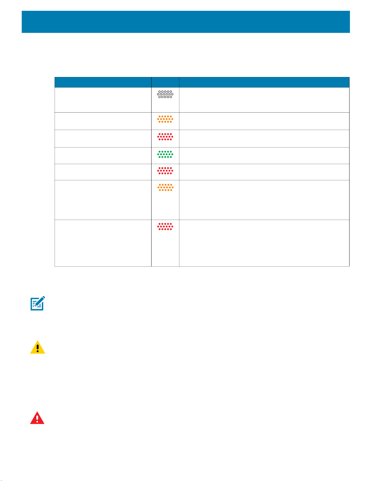
Table 2 Charging/Notification LED Charging Indicators
State LED Indication
Off Device is not charging. Device is not inserted correctly in the
Slow Blinking Amber (1 blink
every 4 seconds)
Slow Blinking Red (1 blink every
4 seconds)
Solid Green Charging complete.
Solid Red Charging complete but the battery is at end of useful life.
Getting Started
cradle or connected to a power source. Charger/cradle is not
powered.
Device is charging.
Device is charging but the battery is at end of useful life.
Fast Blinking Amber (2
blinks/second)
Fast Blinking Red (2
blinks/second)
Replacing the TC52ax Battery
NOTE: User modification of the device, particularly in the battery well, such as labels, asset tags, engravings,
stickers, etc., may compromise the intended performance of the device or accessories. Performance levels
such as sealing (Ingress Protection (IP)), impact performance (drop and tumble), functionality, temperature
resistance, etc. could be effected. DO NOT put any labels, asset tags, engravings, stickers, etc. in the battery
well.
CAUTION: Do not add or remove microSD card during battery replacement.
Charging error, for example:
• Temperature is too low or too high.
• Charging has gone on too long without completion
(typically eight hours).
Charging error but the battery is at end of useful life, for
example:
• Temperature is too low or too high.
• Charging has gone on too long without completion
(typically eight hours).
To replace the battery:
1. Press the Power button until the menu appears.
2. Touch Battery Swap.
3. Follow the on-screen instructions.
WARNING: Do not remove the battery until after the red LED completely turns off. Loss of data may result.
4. Wait for the red LED to completely turn off.
5. If hand strap is attached, remove hand strap.
25

Press the two battery latches in.
6.
7. Lift the battery from the device.
Getting Started
CAUTION: Replace the battery within 75 seconds. After 75 seconds the device reboots and data may be lost.
8. Insert the replacement battery, bottom first, into the battery compartment in the back of the device.
9. Press the battery down until the battery release latches snap into place.
10. Replace the hand strap, if required.
11. Press the Power button to turn on the device.
Replacing the microSD Card
NOTE: User modification of the device, particularly in the battery well, such as labels, asset tags, engravings,
stickers, etc., may compromise the intended performance of the device or accessories. Performance levels
such as sealing (Ingress Protection (IP)), impact performance (drop and tumble), functionality, temperature
resistance, etc. could be effected. DO NOT put any labels, asset tags, engravings, stickers, etc. in the battery
well.
To replace the microSD card:
1. Press the Power button until the menu appears.
2. Touch Power off.
3. Touch OK.
4. If hand strap is attached, slide the hand strap clip up toward the top of the device and then lift.
26

Getting Started
Press the two battery latches in.
5.
6. Lift the battery from the device.
7. Lift the access door.
8. Remove microSD card from holder.
9. Insert the replacement microSD card.
CAUTION: Access door must be replaced and securely seated to ensure proper device sealing.
10. Replace the access door.
11. Insert the battery, bottom first, into the battery compartment in the back of the device.
12. Press the battery down until the battery release latches snap into place.
13. Replace the hand strap, if required.
14. Press and hold the Power button to turn on the device.
27
Using the Device
Home Screen
Turn on the device to display the Home screen. Depending on how your system administrator configured
your device, your Home screen may appear differently than the graphics in this section.
After a suspend or screen time-out, the Home screen displays with the lock slider. Touch the screen and
slide up to unlock.
The Home screen provides four additional screens to place widgets and shortcuts. Swipe the screen left or
right to view the additional screens.
NOTE: By default, AOSP devices do not have the same icons on the Home screen as GMS devices. Icons
are shown below for example only.
Home screen icons can be configured by the user and may look different than shown.
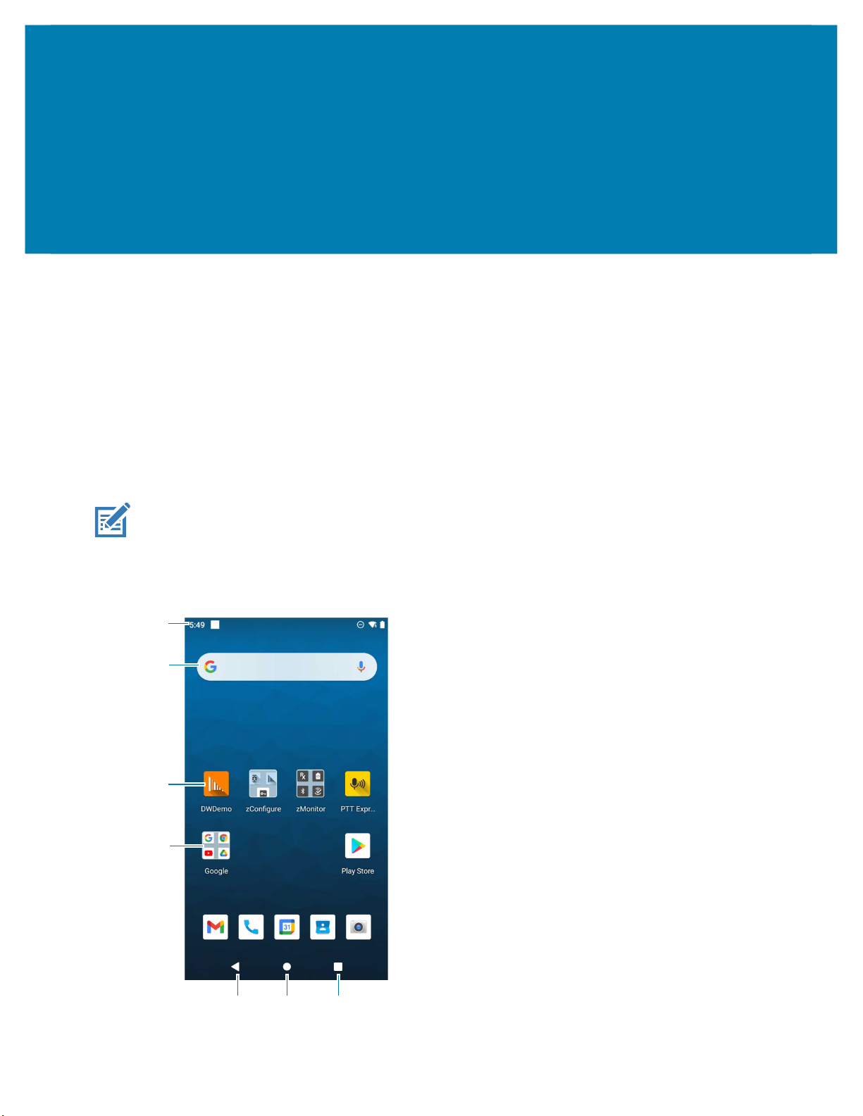
Figure 5 Home Screen
26
1 Status Bar Displays the time, status icons (right side), and notification icons (left side).
For more information see Notification Icons on page 27 and Managing
Notifications on page 29.
2 Widgets Launches stand-alone apps that run on the Home screen.
3 Shortcut Icons Opens apps installed on the device.
4 Folder Contains apps.
5 Back Displays the previous screen.
6 Home Displays the Home screen.
7 Recent Displays recently used applications.
Setting Home Screen Rotation
By default, the Home screen rotation is disabled.
1. Touch and hold anywhere on the Home screen until the options appear.
2. Touch Home settings.
3. Touch the Allow Home screen rotation switch.
Using the Device
4. Touch the Home button.
5. Rotate the device.
Status Bar
The Status bar displays the time, notification icons (left side), and status icons (right side).
If there are more notifications than can fit in the Status bar, a dot displays indicating that more notifications
exist. Swipe down from the Status bar to open the Notification panel and view all notifications and status.
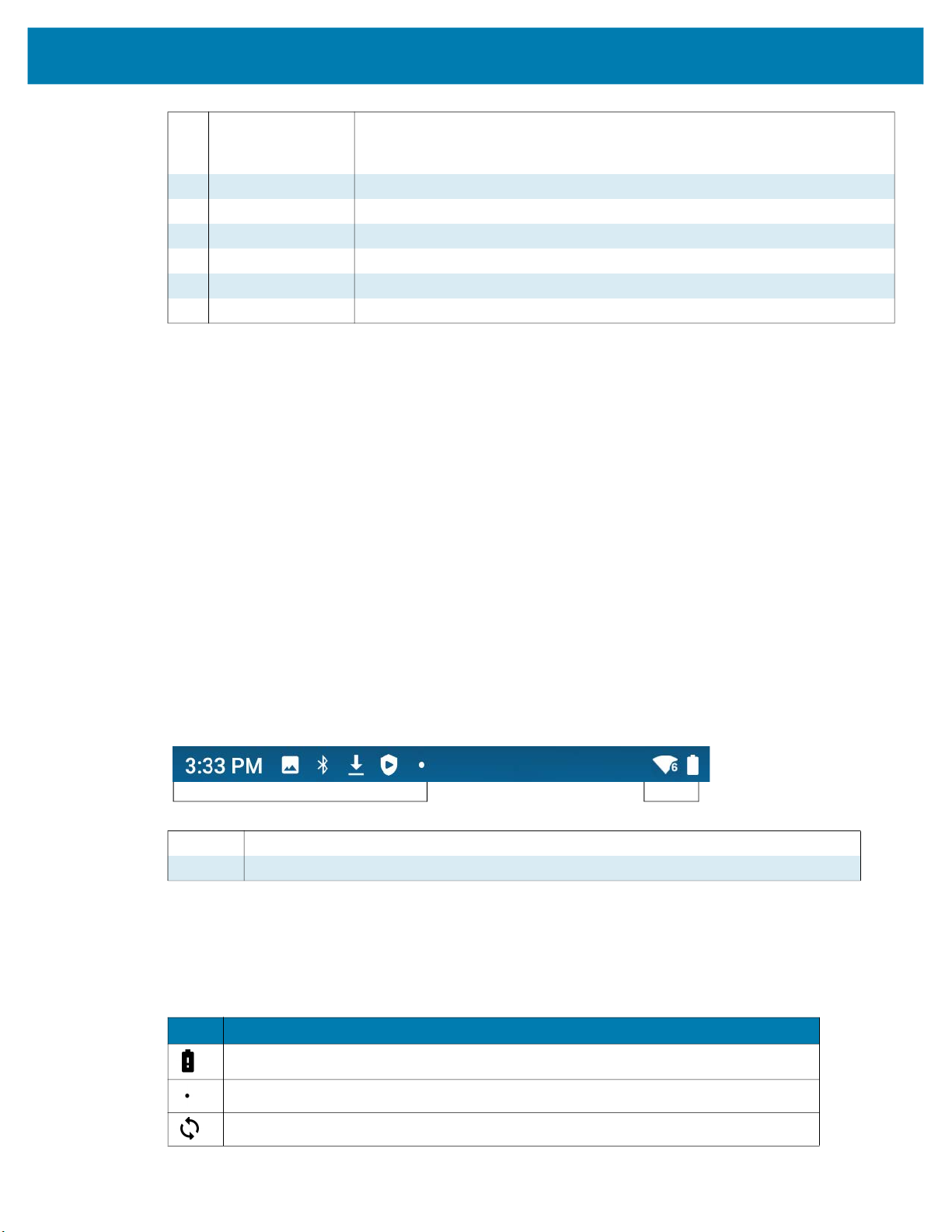
Figure 6 Notification and Status Icons
1 Notification Icons. See Notification Icons on page 27.
2 Status Icons. See Status Icons on page 28.
Notification Icons
Notification icons indicate app events and messages.
1
2
Table 3 Notification Icons
Icon Description
Main battery is low.
More notifications are available for viewing.
Data is syncing.
27
Using the Device
Table 3 Notification Icons (Continued)
Icon Description
Indicates an upcoming event. AOSP devices only.
Indicates an upcoming event. GMS devices only.
Open Wi-Fi network is available.
Audio is playing.
Problem with sign-in or sync has occurred.
Device is uploading data.
Animated: the device is downloading data. Static: the download is complete.
Device is connected to or disconnected from a virtual private network (VPN).
Preparing internal storage by checking it for errors.
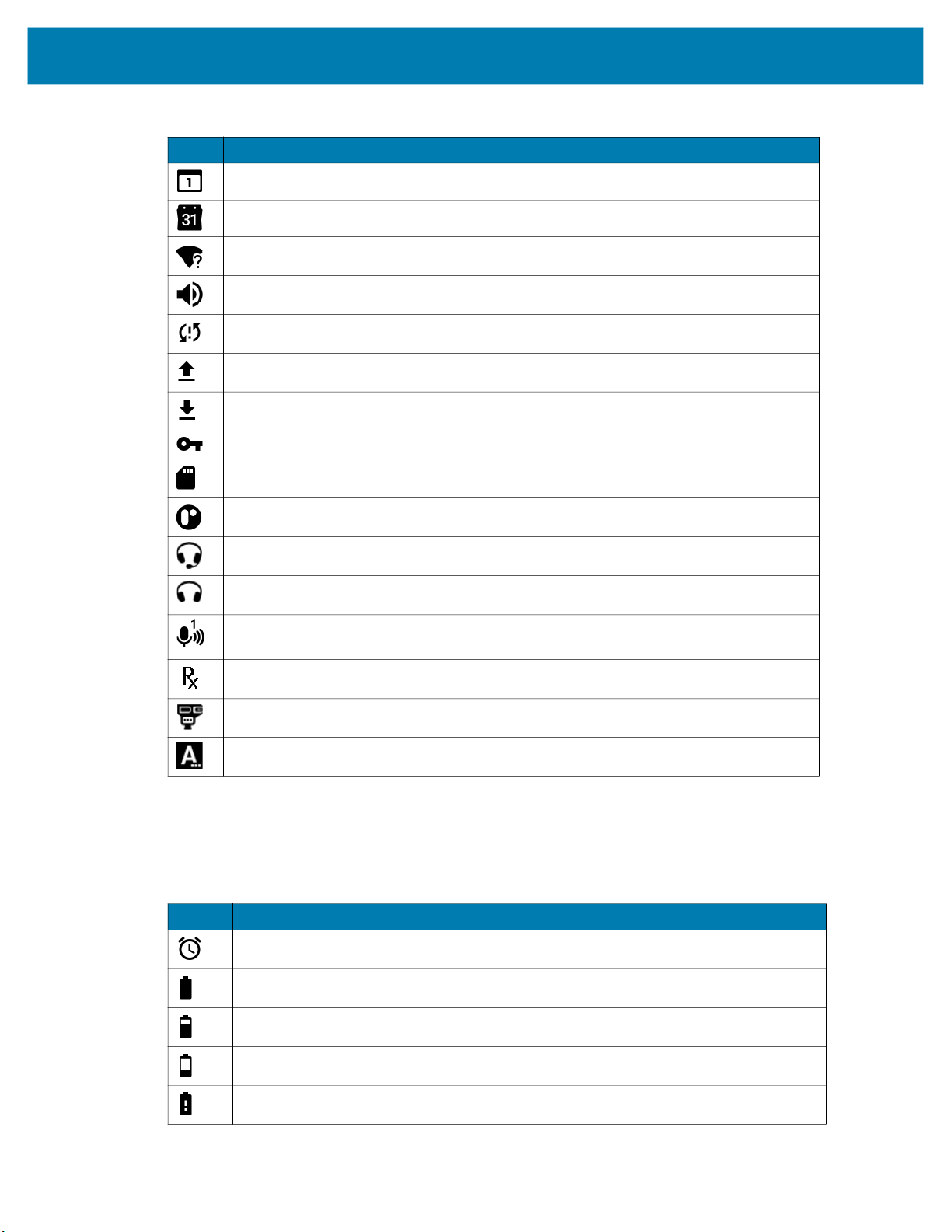
Status Icons
Status icons display system information for the device.
Table 4 Status Icons
Icon Description
USB debugging is enabled on the device.
Wired headset with a boom module is connected to the device.
Wired headset without a boom module is connected to the device.
PTT Express Voice client status. See the PTT Express PTT Notification Icons for a
complete list.
Indicates the RxLogger app is running.
Indicates the Bluetooth scanner is connected to the device.
Indicates the ring scanner is connected to the device in HID mode.
Alarm is active.
Main battery is fully charged.
Main battery is partially drained.
Main battery charge is low.
Main battery charge is very low.
28
 Loading...