


TC51
MN-002869-07
Touch Computer
Integrator Guide
for Android™ Version 6.0.1


TC51 INTEGRATOR GUIDE
FOR ANDROID VERSION 6.0.1
MN-002869-07
Rev A
December 2019

ii TC51 Touch Computer Integrator Guide for Android Version 6.0.1
No part of this publication may be reproduced or used in any form, or by any electrical or mechanical means,
without permission in writing from Zebra. This includes electronic or mechanical means, such as photocopying,
recording, or information storage and retrieval systems. The material in this manual is subject to change
without notice.
The software is provided strictly on an “as is” basis. All software, including firmware, furnished to the user is on
a licensed basis. Zebra grants to the user a non-transferable and non-exclusive license to use each software
or firmware program delivered hereunder (licensed program). Except as noted below, such license may not be
assigned, sublicensed, or otherwise transferred by the user without prior written consent of Zebra. No right to
copy a licensed program in whole or in part is granted, except as permitted under copyright law. The user shall
not modify, merge, or incorporate any form or portion of a licensed program with other program material, create
a derivative work from a licensed program, or use a licensed program in a network without written permission
from Zebra. The user agrees to maintain Zebra’s copyright notice on the licensed programs delivered
hereunder, and to include the same on any authorized copies it makes, in whole or in part. The user agrees not
to decompile, disassemble, decode, or reverse engineer any licensed program delivered to the user or any
portion thereof.
Zebra reserves the right to make changes to any software or product to improve reliability, function, or design.
Zebra does not assume any product liability arising out of, or in connection with, the application or use of any
product, circuit, or application described herein.
No license is granted, either expressly or by implication, estoppel, or otherwise under any Zebra Technologies
Corporation, intellectual property rights. An implied license only exists for equipment, circuits, and subsystems
contained in Zebra products.

Revision History
Changes to the original manual are listed below:
Change Date Description
-01 Rev. A 11/2016 Initial release.
-02 Rev. A 12/2016 Update Ethernet setup information.
iii
-03 Rev. A 05/2017
-04 Rev. A 07/2017
-05 Rev. A 12/2017
-06 Rev. A 8/2018
-07 Rev. A 12/2019
Add TC51-HC (Healthcare) configuration.
Add software update for BSP 19-01.4.
Update Accessories.
Update cleaning procedures.
Updated battery details in Charging the Battery section.

iv TC51 Touch Computer Integrator Guide for Android Version 6.0.1

TABLE OF CONTENTS
Revision History ................................................................................................................................. iii
Table of Contents
About This Guide
Introduction ..................................................................................................................................... xvii
Documentation Set ......................................................................................................................... xvii
Configurations................................................................................................................................. xvii
Software Versions.......................................................................................................................... xviii
Chapter Descriptions ..................................................................................................................... xviii
Notational Conventions.................................................................................................................. xviii
Icon Conventions ............................................................................................................................. xix
Related Documents ......................................................................................................................... xix
Service Information .......................................................................................................................... xix
Provide Documentation Feedback................................................................................................... xx
Chapter 1: Getting Started
Introduction .................................................................................................................................... 1-1
Setup .............................................................................................................................................. 1-1
Installing a microSD Card ........................................................................................................ 1-1
Installing the Battery ................................................................................................................. 1-4
Charging the Battery ................................................................................................................ 1-4
Charging Indicators .................................................................................................................. 1-5
Replacing the Battery ..................................................................................................................... 1-5
Replacing the microSD Card ......................................................................................................... 1-7
Resetting the TC51 ........................................................................................................................ 1-8
Performing a Soft Reset ........................................................................................................... 1-8
Performing a Hard Reset ......................................................................................................... 1-8

vi TC51 Touch Computer Integrator Guide for Android Version 6.0.1
Chapter 2: Accessories
Introduction .................................................................................................................................... 2-1
Accessories .................................................................................................................................... 2-1
1-Slot USB Charge Cradle ............................................................................................................. 2-4
Charging the Device ................................................................................................................. 2-4
Inserting a TC51 with Rugged Boot into Cradle ....................................................................... 2-5
Battery Charging ...................................................................................................................... 2-6
Charging Temperature ....................................................................................................... 2-6
4-Slot Charge Only Cradle with Battery Charger ........................................................................... 2-7
Charging the TC51 ................................................................................................................... 2-7
Inserting a TC51 with Rugged Boot into Cradle ....................................................................... 2-9
Battery Charging ...................................................................................................................... 2-9
Main Battery Charging ....................................................................................................... 2-9
Spare Battery Charging ...................................................................................................... 2-9
Charging Temperature ..................................................................................................... 2-10
5-Slot Charge Only Cradle ........................................................................................................... 2-11
Charging the TC51 ................................................................................................................. 2-11
Inserting a TC51 with Rugged Boot into Cradle ..................................................................... 2-12
Battery Charging .................................................................................................................... 2-13
Charging Temperature ..................................................................................................... 2-13
5-Slot Ethernet Cradle ................................................................................................................. 2-14
Daisy-chaining Ethernet Cradles ............................................................................................ 2-14
Ethernet Settings .............................................................................................................. 2-15
Configuring Ethernet Proxy Settings ................................................................................ 2-15
Configuring Ethernet Static IP Address ............................................................................ 2-16
Charging the TC51 ................................................................................................................. 2-17
Inserting a TC51 with Rugged Boot into Cradle ..................................................................... 2-18
Battery Charging .................................................................................................................... 2-19
Charging Temperature ..................................................................................................... 2-19
Establishing Ethernet Connection .......................................................................................... 2-19
LED Indicators ........................................................................................................................ 2-19
4-Slot Battery Charger ................................................................................................................. 2-20
Charging Spare Batteries ....................................................................................................... 2-20
Single Charger Setup ............................................................................................................. 2-20
Spare Battery Charging .................................................................................................... 2-21
Charging Temperature ..................................................................................................... 2-21
Two Charger Setup ................................................................................................................ 2-22
Spare Battery Charging .................................................................................................... 2-23
Charging Temperature ..................................................................................................... 2-23
Rugged Charge/USB Cable ......................................................................................................... 2-24
Connecting to TC51 ............................................................................................................... 2-24
Connecting to TC51 with Rugged Boot .................................................................................. 2-25
USB Communication .............................................................................................................. 2-26
Charging the Device ............................................................................................................... 2-26
Disconnecting the Rugged Charge/USB Cable ..................................................................... 2-27
Battery Charging .................................................................................................................... 2-28
Main Battery Charging ..................................................................................................... 2-28
Charging Temperature ..................................................................................................... 2-28
5-Slot Cradle Rack Installation ..................................................................................................... 2-29
4-Slot Battery Chargers Rack Installation .................................................................................... 2-32

Table of Contents vii
Rack Mount Installation ................................................................................................................ 2-35
Wall Installation ............................................................................................................................ 2-38
Bottom Tray Assembly ........................................................................................................... 2-38
Bracket Wall Mounting ........................................................................................................... 2-38
Chapter 3: DataWedge
Introduction .................................................................................................................................... 3-1
Basic Scanning .............................................................................................................................. 3-1
Profiles ........................................................................................................................................... 3-2
Profile0 ..................................................................................................................................... 3-2
Plug-ins .......................................................................................................................................... 3-2
Input Plug-ins ........................................................................................................................... 3-3
Process Plug-ins ...................................................................................................................... 3-3
Output Plug-ins ........................................................................................................................ 3-3
Profiles Screen ............................................................................................................................... 3-4
Profile Context Menu ................................................................................................................ 3-4
Options Menu ........................................................................................................................... 3-5
Disabling DataWedge .............................................................................................................. 3-5
Creating a New Profile ................................................................................................................... 3-5
Profile Configuration ...................................................................................................................... 3-6
Associating Applications .......................................................................................................... 3-7
Data Capture Plus .................................................................................................................... 3-9
Bar Code Input ....................................................................................................................... 3-12
Enabled ............................................................................................................................ 3-12
Scanner Selection ............................................................................................................ 3-12
Decoders ................................................................................................................................ 3-13
Decoder Params .................................................................................................................... 3-14
Codabar ........................................................................................................................... 3-15
Code 11 ............................................................................................................................................................ 3-15
Code128 ........................................................................................................................... 3-15
Code39 ............................................................................................................................. 3-16
Code93 ............................................................................................................................. 3-17
Composite AB .................................................................................................................. 3-17
Discrete 2 of 5 .................................................................................................................. 3-17
GS1 DataBar Limited ....................................................................................................... 3-17
HAN XIN ........................................................................................................................... 3-18
Interleaved 2 of 5 ............................................................................................................. 3-18
Matrix 2 of 5 ..................................................................................................................... 3-18
MSI ................................................................................................................................... 3-18
Trioptic 39 ........................................................................................................................ 3-19
UK Postal ......................................................................................................................... 3-19
UPCA ............................................................................................................................... 3-19
UPCE0 ............................................................................................................................. 3-19
UPCE1 ............................................................................................................................. 3-20
US Planet ......................................................................................................................... 3-20
UPC EAN Params .................................................................................................................. 3-20
Reader Params ...................................................................................................................... 3-22
Scan Params .......................................................................................................................... 3-24
Keep enabled on suspend ..................................................................................................... 3-25

viii TC51 Touch Computer Integrator Guide for Android Version 6.0.1
Simulscan Input ...................................................................................................................... 3-25
Keystroke Output ................................................................................................................... 3-26
Intent Output .......................................................................................................................... 3-27
Intent Overview ...................................................................................................................... 3-28
IP Output ................................................................................................................................ 3-29
Usage ..................................................................................................................................... 3-30
Using IP Output with IPWedge ............................................................................................... 3-31
Using IP Output without IPWedge .......................................................................................... 3-32
Generating Advanced Data Formatting Rules ............................................................................. 3-33
Configuring ADF Plug-in ........................................................................................................ 3-33
Creating a Rule ................................................................................................................ 3-34
Defining a Rule ................................................................................................................. 3-34
Defining Criteria ............................................................................................................... 3-35
Defining an Action .................................................................................................................. 3-36
Deleting a Rule ....................................................................................................................... 3-37
Order Rules List ..................................................................................................................... 3-37
Deleting an Action .................................................................................................................. 3-38
ADF Example ......................................................................................................................... 3-39
DataWedge Settings .............................................................................................................. 3-41
Importing a Configuration File ................................................................................................ 3-42
Exporting a Configuration File ................................................................................................ 3-43
Importing a Profile File ........................................................................................................... 3-43
Exporting a Profile .................................................................................................................. 3-43
Restoring DataWedge ............................................................................................................ 3-43
Configuration and Profile File Management ................................................................................. 3-44
Enterprise Folder .................................................................................................................... 3-44
Auto Import ............................................................................................................................. 3-44
Programming Notes ..................................................................................................................... 3-44
Overriding Trigger Key in an Application ................................................................................ 3-44
Capture Data and Taking a Photo in the Same Application ................................................... 3-45
Disable DataWedge on Device and Mass Deploy ................................................................. 3-45
Soft Scan Feature .................................................................................................................. 3-45
Sample ................................................................................................................................... 3-45
Scanner Input Plugin .............................................................................................................. 3-46
Function Prototype ........................................................................................................... 3-46
Parameters ....................................................................................................................... 3-46
Return Values .................................................................................................................. 3-46
Example ........................................................................................................................... 3-47
Comments ........................................................................................................................ 3-47
Enumerate Scanners ............................................................................................................. 3-47
Function Prototype ........................................................................................................... 3-47
Parameters ....................................................................................................................... 3-48
Return Values .................................................................................................................. 3-48
Example ........................................................................................................................... 3-49
Comments ........................................................................................................................ 3-49
Set Default Profile .................................................................................................................. 3-49
Default Profile Recap ....................................................................................................... 3-49
Usage Scenario ................................................................................................................ 3-50
Function Prototype ........................................................................................................... 3-50
Parameters ....................................................................................................................... 3-50

Table of Contents ix
Return Values .................................................................................................................. 3-50
Example ........................................................................................................................... 3-51
Comments ........................................................................................................................ 3-51
Reset Default Profile .............................................................................................................. 3-52
Function Prototype ........................................................................................................... 3-52
Parameters ....................................................................................................................... 3-52
Return Values .................................................................................................................. 3-52
Example ........................................................................................................................... 3-52
Comments ........................................................................................................................ 3-52
Switch To Profile .................................................................................................................... 3-53
Profiles Recap .................................................................................................................. 3-53
Usage Scenario ................................................................................................................ 3-53
Function Prototype ........................................................................................................... 3-53
Parameters ....................................................................................................................... 3-53
Return Values .................................................................................................................. 3-54
Example ........................................................................................................................... 3-54
Comments ........................................................................................................................ 3-54
Notes ................................................................................................................................ 3-55
Chapter 4: USB Communication
Introduction .................................................................................................................................... 4-1
Transferring Files using Media Transfer Protocol .................................................................... 4-1
Transferring Files using Photo Transfer Protocol ..................................................................... 4-2
Disconnect from the Host Computer ........................................................................................ 4-2
Chapter 5: Settings
Introduction .................................................................................................................................... 5-1
WLAN Configuration ...................................................................................................................... 5-1
Configuring a Wi-Fi Network .................................................................................................... 5-1
Manually Adding a Wi-Fi Network ............................................................................................ 5-2
Configuring for a Proxy Server ................................................................................................. 5-3
Configuring the Device to Use a Static IP Address .................................................................. 5-4
Advanced Wi-Fi Settings .......................................................................................................... 5-5
Screen Unlock Settings .................................................................................................................. 5-7
Set Screen Unlock Using PIN ............................................................................................ 5-8
Set Screen Unlock Using Password .................................................................................. 5-9
Set Screen Unlock Using Pattern ..................................................................................... 5-10
Passwords ................................................................................................................................... 5-11
Button Remapping ....................................................................................................................... 5-12
Remapping a Button .............................................................................................................. 5-12
Accounts ...................................................................................................................................... 5-13
Language Usage .......................................................................................................................... 5-13
Changing the Language Setting ............................................................................................. 5-14
Adding Words to the Dictionary .............................................................................................. 5-14
Keyboard Settings ........................................................................................................................ 5-14
PTT Express Configuration .......................................................................................................... 5-14
RxLogger ..................................................................................................................................... 5-14
RxLogger Configuration ......................................................................................................... 5-15

x TC51 Touch Computer Integrator Guide for Android Version 6.0.1
Main Log Plug-in .............................................................................................................. 5-16
Snapshot Plug-in .............................................................................................................. 5-17
Logcat Plug-in .................................................................................................................. 5-17
PushPullClient Plug-in ...................................................................................................... 5-19
TCPDump Plug-in ............................................................................................................ 5-19
ANR Plugin ....................................................................................................................... 5-20
Kernal Plug-in ................................................................................................................... 5-20
Configuration File ................................................................................................................... 5-20
Enabling Logging ................................................................................................................... 5-20
Disabling Logging ................................................................................................................... 5-20
Extracting Log Files ................................................................................................................ 5-21
About Phone ................................................................................................................................ 5-21
Chapter 6: Application Deployment
Introduction .................................................................................................................................... 6-1
Security .......................................................................................................................................... 6-1
Secure Certificates ......................................................................................................................... 6-1
Installing a Secure Certificate ........................................................................................................ 6-1
Configuring Credential Storage Settings .................................................................................. 6-2
Development Tools ........................................................................................................................ 6-2
Android ..................................................................................................................................... 6-2
EMDK for Android .................................................................................................................... 6-4
StageNow ................................................................................................................................. 6-4
ADB USB Setup ............................................................................................................................. 6-4
Enabling USB Debugging ........................................................................................................ 6-4
Application Installation ................................................................................................................... 6-5
Installing Applications Using the USB Connection ................................................................... 6-5
Installing Applications Using the Android Debug Bridge .......................................................... 6-7
Installing Applications Using a microSD Card .......................................................................... 6-8
Uninstalling an Application ....................................................................................................... 6-8
Performing a System Update ......................................................................................................... 6-9
Download the System Update Package ................................................................................... 6-9
Using microSD Card .............................................................................................................. 6-10
Using ADB .............................................................................................................................. 6-11
Verify System Update Installation .......................................................................................... 6-11
Performing an Enterprise Reset ................................................................................................... 6-12
Download the Enterprise Reset Package .............................................................................. 6-12
Using microSD Card .............................................................................................................. 6-12
Using ADB .............................................................................................................................. 6-12
Performing a Factory Reset ......................................................................................................... 6-13
Download the Factory Reset Package ................................................................................... 6-13
Using microSD Card .............................................................................................................. 6-13
Using ADB .............................................................................................................................. 6-14
Storage ........................................................................................................................................ 6-15
Random Access Memory ....................................................................................................... 6-15
Internal Storage ...................................................................................................................... 6-16
External Storage .................................................................................................................... 6-18
Formatting a microSD Card ............................................................................................. 6-20
Format as Internal Memory .............................................................................................. 6-22

Table of Contents xi
Enterprise Folder .................................................................................................................... 6-24
Application Management ............................................................................................................. 6-24
Viewing Application Details .................................................................................................... 6-25
Managing Downloads .................................................................................................................. 6-26
Chapter 7: Maintenance and Troubleshooting
Introduction .................................................................................................................................... 7-1
Maintaining the TC51 ..................................................................................................................... 7-1
Display Best Practices ................................................................................................................... 7-2
Image Retention ....................................................................................................................... 7-2
Battery Safety Guidelines .............................................................................................................. 7-2
Cleaning Instructions ..................................................................................................................... 7-3
Approved Cleanser Active Ingredients ..................................................................................... 7-3
Approved Disinfectant Cleaners for TC51-Healthcare ............................................................. 7-4
Harmful Ingredients .................................................................................................................. 7-4
Cleaning Instructions ................................................................................................................ 7-4
Special Cleaning Notes ............................................................................................................ 7-4
Recommended Cleaning Materials .......................................................................................... 7-5
TC51-Standard and Healthcare ......................................................................................... 7-5
TC51-Healthcare Only ....................................................................................................... 7-5
Cleaning Frequency ................................................................................................................. 7-5
Cleaning the TC51 ......................................................................................................................... 7-5
Housing .................................................................................................................................... 7-5
Display ..................................................................................................................................... 7-5
Camera and Exit Window ......................................................................................................... 7-5
Battery Guide Slots .................................................................................................................. 7-6
Battery Connector and Locating Magnet Cleaning ........................................................................ 7-6
Cleaning Cradle Connectors .......................................................................................................... 7-7
Troubleshooting ............................................................................................................................. 7-8
Device Diagnostic Tool ............................................................................................................ 7-8
Settings ............................................................................................................................ 7-11
Battery Test Information ................................................................................................... 7-11
GPS Test Information ....................................................................................................... 7-12
System Test Information .................................................................................................. 7-12
WLAN Test Information .................................................................................................... 7-12
WWAN Test Information .................................................................................................. 7-12
Bluetooth Test Information ............................................................................................... 7-12
TC51 ...................................................................................................................................... 7-13
1-Slot Charge Only Cradle ..................................................................................................... 7-15
4-Slot Charge Only Cradle with Battery Charger Troubleshooting ........................................ 7-16
5-Slot Charge Only Cradle Troubleshooting .......................................................................... 7-17
5-Slot Ethernet Cradle Troubleshooting ................................................................................. 7-18
4-Slot Battery Charger Troubleshooting ................................................................................. 7-18
Appendix A: Technical Specifications
TC51 ............................................................................................................................................. A-1
Decode Distances ................................................................................................................... A-4
I/O Connector Pin-Outs ........................................................................................................... A-5

xii TC51 Touch Computer Integrator Guide for Android Version 6.0.1
1-Slot Charge Only Cradle Technical Specifications .............................................................. A-5
4-Slot Charge Only Cradle with Battery Charger Technical Specifications ............................. A-6
5-Slot Charge Only Cradle Technical Specifications .............................................................. A-7
5-Slot Ethernet Cradle Technical Specifications ..................................................................... A-7
4-Slot Battery Charger Technical Specifications ..................................................................... A-8
Trigger Handle Technical Specifications ................................................................................. A-9
Rugged Charge/USB Cable Technical Specifications ............................................................ A-9

ABOUT THIS GUIDE
Introduction
This guide provides information about using the TC51 touch computer and accessories. The TC51 refers to both
the TC51 (Standard) and TC51-HC (Healthcare) configurations, except where noted.
NOTE Screens and windows pictured in this guide are samples and can differ from actual screens.
Documentation Set
The documentation set for the TC51 provides information for specific user needs, and includes:
•
TC51 Touch Computer Quick Start Guide - describes how to get the TC51 up and running.
•
TC51 Touch Computer User Guide for Android Version 6.0.1 - describes how to use the TC51.
•
TC51 Touch Computer Integrator Guide for Android Version 6.0.1 - describes how to set up the TC51 and
accessories.
Configurations
This guide covers the following configurations:

xviii TC51 Touch Computer Integrator Guide for Android Version 6.0.1
Configuration Radios Display Memory
TC510K-1 WLAN: 802.11
a/b/g/n/d/h/i/k/r
WPAN: Bluetooth
v4.1 Low Energy
TC510K-2 WLAN: 802.11
a/b/g/n/d/h/i/k/r
WPAN: Bluetooth
v4.1 Low Energy
Software Versions
To determine the current software versions touch > About phone.
•
Model number- Displays the model number.
•
Android version - Displays the operating system version.
•
Kernel version - Displays the kernel version number.
•
Build number - Displays the software build number.
To determine the device serial number touch > About phone > Status.
5.0” High
Definition (1280 x
720) LCD
5.0” High
Definition (1280 x
720) LCD
2 GB RAM / 16
GB Flash or 4 GB
RAM / 32 GB
Flash
2 GB RAM / 16
GB Flash or 4 GB
RAM / 32 GB
Flash
Data Capture
Options
2D imager
(SE-4710) and
integrated NFC
2D imager
(SE-4710) and
integrated NFC
Operating
System
Android-based,
Google™ Mobile
Services (GMS)
6.0.1.
Android-based,
Android
Open-Source
Project 6.0.1
•
Serial number - Displays the serial number.
Chapter Descriptions
Topics covered in this guide are as follows:
•
Chapter 1, Getting Started provides information on getting the TC51 up and running for the first time.
•
Chapter 2, Accessories describes the available accessories and how to use them with the TC51.
•
Chapter 3, DataWedge describes how to use and configure the DataWedge application.
•
Chapter 5, Settings provides the settings for configuring the TC51.
•
Chapter 6, Application Deployment provides information for developing and managing applications.
•
Chapter 7, Maintenance and Troubleshooting includes instructions on cleaning and storing the TC51, and
provides troubleshooting solutions for potential problems during TC51 operation.
•
Appendix A, Technical Specifications provides the technical specifications for the TC51.
Notational Conventions
The following conventions are used in this document:

About This Guide xix
•
Italics are used to highlight the following:
• Chapters and sections in this and related documents
• Icons on a screen.
•
Bold text is used to highlight the following:
• Dialog box, window, and screen names
• Drop-down list and list box names
• Check box and radio button names
• Button names on a screen.
•
Bullets (•) indicate:
• Action items
• Lists of alternatives
• Lists of required steps that are not necessarily sequential
•
Sequential lists (for example, lists that describe step-by-step procedures) appear as numbered lists.
Icon Conventions
The documentation set is designed to give the reader more visual clues. The following graphic icons are used
throughout the documentation set. These icons and their associated meanings are described below.
NOTE NOTE contains information more important than the surrounding text, such as exceptions or
preconditions. They also refer the reader elsewhere for additional information, remind the reader how to
complete an action (when it is not part of the current procedure, for instance), or tell the reader where
something is located on the screen. There is no warning level associated with a note.
CAUTION The word CAUTION with the associated safety icon implies information that, if disregarded, may result
in minor or moderate injury, or serious product damage.
WARNING! The word WARNING with the associated safety icon implies information that, if disregarded,
could result in death or serious injury, or serious product damage.
Related Documents
•
TC51 Touch Computer Quick Start Guide, p/n MN-002879-xx.
•
TC51 Touch Computer Regulatory Guide, p/n MN-002880-xx.
•
TC51 Touch Computer User Guide for Android Version 6.0.1, p/n MN-002868-xx.
For the latest version of this guide and all guides, go to: http://www.zebra.com/support.
Service Information
If you have a problem with the equipment, contact Customer Support in the region. Contact information is available
at: http://www.zebra.com/support
.

xx TC51 Touch Computer Integrator Guide for Android Version 6.0.1
When contacting support, please have the following information available:
•
Serial number of the unit (found on manufacturing label)
•
Model number or product name (found on manufacturing label)
•
Software type and version number
Customer Support responds to calls by email or telephone within the time limits set forth in support agreements.
If the problem cannot be solved by Customer Support, the user may need to return the equipment for servicing and
will be given specific directions. We are not responsible for any damages incurred during shipment if the approved
shipping container is not used. Shipping the units improperly can possibly void the warranty. Remove the microSD
card from the device before shipping for service.
If the device was purchased from a business partner, contact that business partner for support.
Provide Documentation Feedback
If you have comments, questions, or suggestions about this guide, send an email to EVM-Techdocs@zebra.com.

CHAPTER 1 GETTING STARTED
Introduction
This chapter provides information for getting the device up and running for the first time.
Setup
Perform this procedure to start using the TC51 for the first time.
1. Install a micro secure digital (SD) card (optional).
2. Install the battery.
3. Charge the TC51.
4. Power on the TC51.
Installing a microSD Card
The microSD card slot provides secondary non-volatile storage. The slot is located under the battery pack. Refer to
the documentation provided with the card for more information, and follow the manufacturer’s recommendations for
use.
CAUTION Follow proper electrostatic discharge (ESD) precautions to avoid damaging the microSD card. Proper
ESD precautions include, but are not limited to, working on an ESD mat and ensuring that the operator
is properly grounded.
1. Lift the access door.

1 - 2 TC51 Touch Computer Integrator Guide for Android Version 6.0.1
Figure 1-1 Lift Access Door
2. Slide the microSD card holder to the unlock position.
Figure 1-2 Unlock microSD Card Holder
3. Lift the microSD card holder.
Figure 1-3 Lift the microSD Card Holder
4. Insert the microSD card into the card holder door ensuring that the card slides into the holding tabs on each
side of the door.

Figure 1-4 Insert microSD Card in Holder
5. Close the microSD card holder and slide into the lock position.
Getting Started 1 - 3
Figure 1-5 Re-install Access Door
CAUTION Access door must be replaced and securely seated to ensure proper device sealing.
6. Re-install the access door.
Figure 1-6 Replace Access Door

1 - 4 TC51 Touch Computer Integrator Guide for Android Version 6.0.1
Installing the Battery
1. Insert the battery, bottom first, into the battery compartment in the back of the TC51.
Figure 1-7 Insert Bottom of Battery into Battery Compartment
2. Press the battery down into the battery compartment until the battery release latches snap into place.
Charging the Battery
Before using the TC51 for the first time, charge the main battery until the green Charging/Notification light emitting
diode (LED) remains lit. To charge the TC51 use a cable or a cradle with the appropriate power supply. For
information about the accessories available for the TC51 see Chapter 2, Accessories for more information.
15.48 Watt hours (typical) / > 4,150 mAh battery charges from fully depleted to 90% in approximately 2.5
The >
hours and from fully depleted to 100% in approximately three hours.
NOTE In many cases the 90% charge provides plenty of charge for daily use. A full 100% charge lasts for
approximately 14 hours of use.
To achieve the best fast charging results use only Zebra charging accessories and batteries. Charge
batteries at room temperature with the TC51 in sleep mode.
Charge batteries in temperatures from 0°C to 40°C (32°F to 104°F). The TC51 or accessory always performs
battery charging in a safe and intelligent manner. At higher temperatures (e.g. approximately +37°C (+98°F)) the
TC51 or accessory may for small periods of time alternately enable and disable battery charging to keep the
battery at acceptable temperatures. The TC51 or accessory indicates when charging is disabled due to abnormal
temperatures via its LED and a notification appears on the display.
1. To charge the main battery, connect the charging accessory to the appropriate power source.
2. Insert the TC51 into a cradle or attach to a cable. The TC51 turns on and begins charging. The
Charging/Notification LED blinks amber while charging, then turns solid green when fully charged.

Getting Started 1 - 5
Charging Indicators
Table 1-1 Charging/Notification LED Charging Indicators
State LED Indication
Off TC51 is not charging. TC51 is not inserted correctly in the
cradle or connected to a power source. Charger/cradle is
not powered.
Slow Blinking Amber (1 blink every 4
seconds)
Slow Blinking Red (1 blink every 4
seconds)
Solid Green Charging complete.
Solid Red Charging complete but the battery is at end of useful life.
Fast Blinking Amber (2 blinks/second) Charging error, e.g.:
Fast Blinking Red (2 blinks/second) Charging error but the battery is at end of useful life., e.g.:
Replacing the Battery
TC51 is charging.
TC51 is charging but the battery is at end of useful life.
• Temperature is too low or too high.
• Charging has gone on too long without completion
(typically eight hours).
• Temperature is too low or too high.
• Charging has gone on too long without completion
(typically eight hours).
CAUTION Do not add or remove microSD card during battery replacement.
1. Press the Power button until the menu appears.
2. Touch Battery Swap.
3. Follow the on-screen instructions.
4. Wait for the LED to turn off.
5. If hand strap is attached, remove hand strap.
6. Press the two battery latches in.

1 - 6 TC51 Touch Computer Integrator Guide for Android Version 6.0.1
Figure 1-8 Press Battery Latches
7. Lift the battery from the TC51.
Figure 1-9 Lift the Battery
CAUTION Replace the battery within two minutes. After two minutes the device reboots and data may be lost.
8. Insert the replacement battery, bottom first, into the battery compartment in the back of the TC51.
9. Press the battery down until the battery release latches snap into place.
10. Replace the hand strap, if required.
11. Press the Power button to turn on the TC51.

Replacing the microSD Card
To replace the microSD card:
1. Press the Power button until the menu appears.
2. Touch Power off.
3. Touch OK.
4. If hand strap is attached, slide the hand strap clip up toward the top of the TC51 and then lift.
5. Press the two battery latches in.
6. Lift the battery from the TC51.
7. Lift the access door.
Getting Started 1 - 7
Figure 1-10 Remove Access Door
8. Remove microSD card from holder.
9. Insert the replacement microSD card.
CAUTION Access door must be replaced and securely seated to ensure proper device sealing.
10. Replace the access door.
Figure 1-11 Replace Access Door
11. Insert the battery, bottom first, into the battery compartment in the back of the TC51.

1 - 8 TC51 Touch Computer Integrator Guide for Android Version 6.0.1
12. Press the battery down until the battery release latches snap into place.
13. Replace the hand strap, if required.
14. Press and hold the Power button to turn on the TC51.
Resetting the TC51
There are four reset functions:
• Soft reset
• Hard reset
• Enterprise reset. See Performing an Enterprise Reset on page 6-12.
• Factory reset See Performing a Factory Reset on page 6-13.
Performing a Soft Reset
Perform a soft reset if applications stop responding.
1. Press and hold the Power button until the menu appears.
2. Touch Reboot and then select OK.
3. The device reboots.
Performing a Hard Reset
CAUTION Performing a hard reset with a SD card installed in the TC51 may cause damage or data corruption to
the SD card.
Perform a hard reset if the TC51 stops responding.
1. Simultaneously press the Power, PTT button and Volume Up buttons for at least four seconds.
2. When the screen turns off, release the buttons.
3. The device reboots.

CHAPTER 2 ACCESSORIES
Introduction
This chapter provides information for using the accessories for the device.
Accessories
This table lists the accessories available for the TC51.
Table 2-1 TC51 Accessories
Accessory Part Number Description
Cradles
1-Slot USB/Charge Only
Cradle Kit
4-Slot Charge Only Cradle
with Battery Charger Kit
5-Slot Charge Only Cradle
Kit
5-Slot Ethernet Cradle Kit CRD-TC51-5SETH-01 Provides device charging and provides Ethernet
Cradle Mount BRKT-SCRD-SMRK-01 Mounts the 5-Slot Charge Only Cradle, 5-Slot
Batteries and Chargers
CRD-TC51-1SCU-01 Provides device charging and communication.
Includes cradle, power supply,
(PWR-BGA12V50W0WW) and DC line cord.
CRD-TC51-5SC4B-01 Charges up to four devices and four spare
batteries. Includes, cradle, power supply,
(PWR-BGA12V108W0WW) and DC line cord.
CRD-TC51-5SCHG-01 Charges up to five devices. Includes, cradle,
power supply, (PWR-BGA12V108W0WW) and
DC line cord.
communication for up to five devices. Includes
cradle, power supply, and DC line cord.
Ethernet Cradle, and 4-Slot Battery Charger to a
wall or rack.

2 - 2 TC51 Touch Computer Integrator Guide for Android Version 6.0.1
Table 2-1 TC51 Accessories (Continued)
Accessory Part Number Description
PowerPrecisionPlus battery BTRY-TC51-43MA1-01
BTRY-TC51-43MA1-10
4-Slot Battery Charger Kit SAC-TC51-4SCHG-01 Charges up to four battery packs. Includes
Vehicle Solutions
Cigarette Light Adapter
Auto Charge Cable
Charge and Communication Cables
Rugged Charge/USB Cable CBL-TC51-USB1-01 Provides communication and power to the
Audio Accessories
2.5 mm Audio Adapter CBL-TC51-HDST25-01 Plugs into the device and provides audio to a
2.5 mm Headset HDST-25MM-PTVP-01 Use for PTT and VoIP calls
3.5 mm Audio Adapter CBL-TC51-HDST35-01 Plugs into the device and provides audio to a
3.5 mm Headset HDST-35MM-PTVP-01 Use for PTT and VoIP calls.
CHG-AUTO-USB1-01 Provides power to the device from a cigarette
Replacement battery (single pack).
Replacement battery (10–pack).
cradle, power supply and DC line cord
lighter socket.
device. Use with power supply, p/n
PWRS-14000-249R, sold separately.
wired headset with 2.5 mm plug.
wired headset with collared 3.5 mm plug.
Miscellaneous
Rugged Boot SG-TC51-EXO1-01 Provides additional protection for the device.
Requires power supply PWR-WUA5V12W0xx.
Trigger Handle TRG-TC51-SNP1-01 Adds gun-style handle with a scanner trigger for
comfortable and productive scanning. Requires
Rugged Boot.
Trigger Handle Kit (with
Rugged Boot)
Screen Protector KT-TC51-SCRNP1-01 Add additional screen protection.
Carrying Solutions
Soft Holster SG-TC51-HLSTR1-01 Use to hold the device on hip. Accepts device
Hand Strap SG-TC51-EHDSTP1-03 Replacement hand strap with hand strap
Basic Hand Strap SG-TC51-BHDSTP1-03 Provide a hand strap to assist in holding the
Stylus and Coiled Tether SG-TC7X-STYLUS-03 Stylus with coiled tether (3-pack).
TRG-TC51-TRG1-01 Adds gun-style handle with a scanner trigger for
comfortable and productive scanning.
with Rugged Boot and Trigger Handle
mounting clip (3–pack).
TC51 without a Rugged Boot.

Accessories 2 - 3
Table 2-1 TC51 Accessories (Continued)
Accessory Part Number Description
Power Supplies
Power Supply PWR-BGA12V50W0WW Provides power to the 1-Slot USB Charge cradle
and 4-Slot Spare Battery Charger. Requires AC
line cord.
Power Supply PWR-BGA12V108W0WW Provides power to the 4-Slot Charge Only
Cradle with battery Charger, 5-Slot Charge Only
cradle and the 5-Slot Ethernet Cradle. Requires
DC Line Cord, p/n 50–16002–029R and country
specific three wire grounded AC line cord sold
separately.
Power Supply PWR-WUA5V12W0US Provides 12 VDC, 2.5 A power to the Rugged
Charge/USB cable. Includes plug adapter for
use in United States.
Power Supply PWR-WUA5V12W0GB Provides 12 VDC, 2.5 A power to the Rugged
Charge/USB cable. Includes plug adapter for
use in the European Union.
Power Supply PWR-WUA5V12W0EU Provides 12 VDC, 2.5 A power to the Rugged
Charge/USB cable. Includes plug adapter for
use in United Kingdom.
Power Supply PWR-WUA5V12W0AU Provides 12 VDC, 2.5 A power to the Rugged
Charge/USB cable. Includes plug adapter for
use in Australia.
Power Supply PWR-WUA5V12W0CN Provides 12 VDC, 2.5 A power to the Rugged
Charge/USB cable. Includes plug adapter for
use in China.
Power Supply PWR-WUA5V12W0IN Provides 12 VDC, 2.5 A power to the Rugged
Charge/USB cable. Includes plug adapter for
use in India.
DC Line Cord CBL-DC-382A1-01 Provides power from the power supply
(PWR-BGA12V108W0WW) to the 4-Slot
Charge Only Cradle with Battery Charger, 5-Slot
Charge Only Cradle and 5-Slot Ethernet Cradle.
DC Line Cord CBL-DC-388A1-01 Provides power from the power supply
(PWR-BGA12V50W0WW) to the 1-Slot
USB/Charge Only Cradle and 4-Slot Battery
Charger.
2-way DC Cable CBL-DC-523A1-01 Connects one power supply
(PWR-BGA12V108W0WW) to two 4-Slot
Battery Chargers.
2 - 4 TC51 Touch Computer Integrator Guide for Android Version 6.0.1
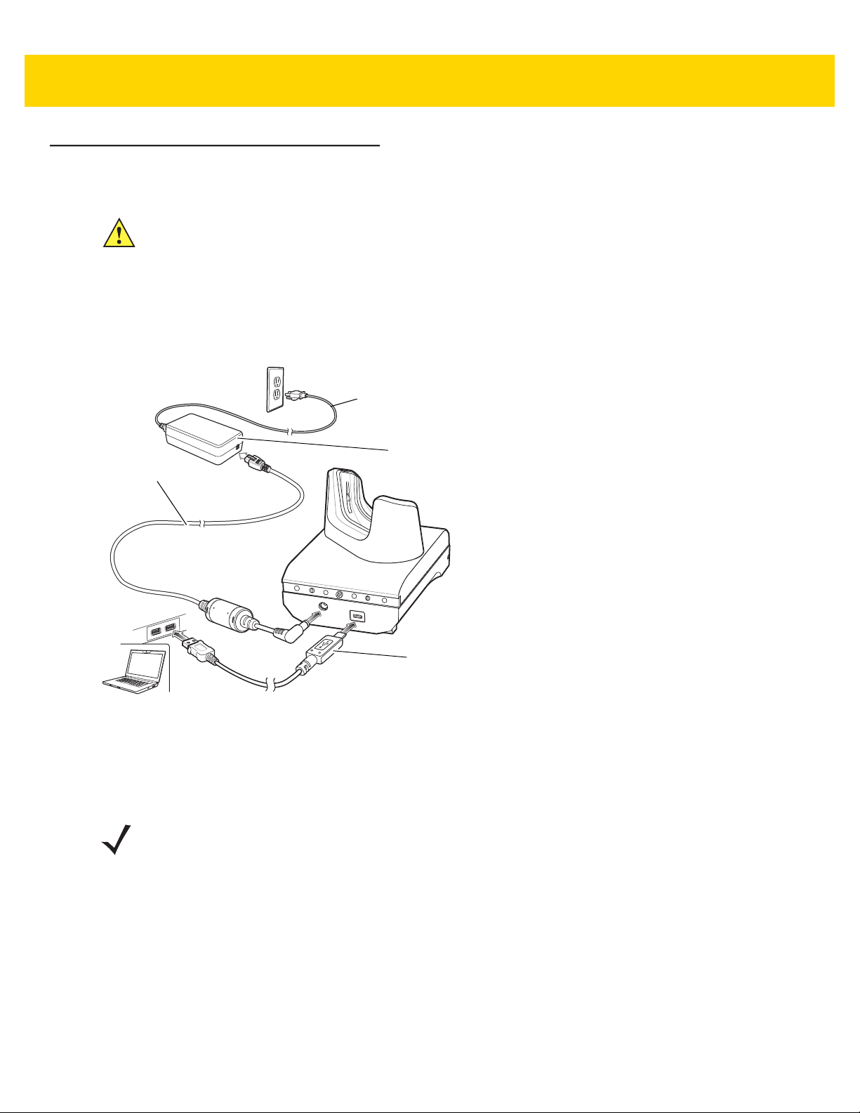
1-Slot USB Charge Cradle
CAUTION Ensure that you follow the guidelines for battery safety described in Battery Safety Guidelines on page
7-2.
The 1-Slot USB Charge Cradle:
• Provides 5 VDC power for operating the device.
• Charges the device’s battery.
• Provides USB communication with host computer.
AC Line Cord
Power Supply
DC Line Cord
Figure 2-1 1–Slot USB Charge Cradle Setup
Charging the Device
To charge a device:
NOTE If the device has a Rugged Boot, remove the cup insert before inserting the device. See TC51 Touch
Computer Integrator Guide for Android Version 6.0.1 for details.
USB Cable
 Loading...